Embed Size (px)
Citation preview
Aermecparticipate in the EUROVENTprogram: FCHthe products are present on the sitewww.eurovent-certification.com
Cassette type fan coilCeiling and false ceiling installation, cooling power from 1900 up to 11000WFCL
• 8 sizes for 2-pipe versions: FCL 32-36-42-62-72-82-102-122• 7 sizes for 4-pipe versions: FCL 34-38-44-64-84-104-124• Standard preparation with standard internal three-
way valve, with fast connection actuator and position visual signalling.
• FCL_V2 preparation (available upon request), with internal two-way valve, suitable for variable water flow rate systems.
• FCL_VL preparation (available upon request), without internal valve.
• Grille dimensions perfectly integrable in standard suspended ceiling panels of 600x600mm and 840x840mm for the most powerful units.
For more details refer to the accessories• Fan designed for low sound emissions.• 3-speed and 4-speed mixed flow (axial + centrifugal)
fan unit for larger sizes (FCL 42-44-62-64-72-82-84-102-104-122-124), in order to select the 3 speeds that best meet delivered power and quiet operation requi-rements.
• The load-bearing structure, reinforced with a galvani-sed steel side band, contains insulation elements in expanded polystyrene obtained from injection moul-ding for purposes of noise reduction and air routing (FCL 42-44-62-72-64).
• Structure made entirely of galvanised steel, contai-ning insulation elements in closed cell expanded polystyrene and externally covered with anti-conden-sate felt (FCL 82-84-102-104-122-124).
• Condensation drip tray in one piece, with V0 self-extinguishing level and overmoulding to insulation in expanded polystyrene with flame retardant additive.
• Heat exchanger with shaped profile to increase the exchange surface, and easily accessible drain valves.
• Continuous fan operation to prevent stratification of room air.
• Possibility of direct release of external air regardless of indoor unit ventilation.
• Possibility to control the climate of adjacent rooms as well. The versions FCL 82-84-102-104-122-124 allow 3-direction delivery.
• Air filter easily removed and cleaned, self-supporting structure, characterised by a high efficiency and low pressure drops, with class-V0 fire resistance (UL 94).
• Electrostatically pre-charged air filter regenerated with fire resistance class 2 (UL 900), (FEL 10 accessory for GLL10, GLL10R, GLL10M).
• Full compliance with safety regulations.• Easy installation and maintenance.
Features
• STANDARD INTERNAL 3-WAY VALVE • VERSION WITH 2-WAY VALVE FOR VARIABLE WATER FLOW RATE SYSTEMS
• VERSIONS WITHOUT VALVS• FAN PURPOSELY DESIGNED FOR LOW SOUND EMISSIONS
• VERSIONS FOR 2-PIPE AND 4-PIPE SYSTEMS• ALSO AVAILABLE WITH ELECTRIC HEATER FOR HEATING
Models :FCL 32 ... FCL72
Models :FCL 32 ... FCL72
Models :FCL 82 ... FCL124
GLLWhite RAL 9010
FCLMCWhite RAL 9010
Remote Control included for GLL10M
GLL10R - GLL20R
GLF10White RAL 9010
Compulsory accessories GLF and GLL, are essential for the operation of the units:• GLF10 (600x600) White RAL 9010. Delivery grille with louvers manually adjustable and
air intake. Combined with wall-mounted control panel.
Compatible with VMF = no; Compatible with the electrical resistance = no• GLF10M (600x600) White RAL 9010.
Delivery grille with adjustable louvers by means of a remote control and air intake, supplied with an infra-red receiver with emergency operation switch.
Compatible with VMF= si; Compatible with the electrical resistance = si• GLF10N (600x600) White RAL 9010. Delivery grille with Manually adjustable fins and air
intake, with "VMF System" advanced electronic ther-mostat. Individual units, or network master also requi-
res a wired control panel (VMF-E4 compulsory acces-sory).
Compatible with VMF = si; Compatible with the electrical resistance = si• GLF10EH (600x600) White RAL 9010 . Outlet grille with manually adjustable fins and air intake.
Prepared for coupling with the RXLE electrical resistance accessory, which can be controlled by an external thermo-stat, also not supplied by Aermec, provided that the mini-
Accessories
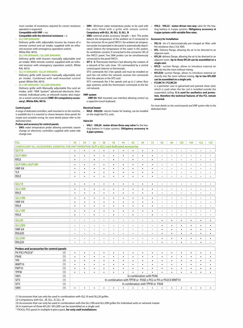
(1) Accessories that can only be used in combination with GLL10 and GLL20 grilles.(2) Compulsory with GLL_M, GLL_R, GLL_N(3) Accessories that can only be used in combination with the GLL10N and GLL20N grilles for individual units or network master(4) A maximum of three KFL20 / KFL20D can be assembled on a single unit* PX2C6, PX2 panel in multiple 6-piece pack, for only wall installations
mum number of revolutions required for correct resistance operation is respected.
Compatible with VMF = no; Compatible with the electrical resistance = si• GLL10M (600x600) Delivery grille with adjustable louvers by means of a
remote control and air intake, supplied with an infra-red receiver with emergency operation switch.
White RAL 9010.• GLL10R (600x600) / GLL20R (840x840) Delivery grille with louvers manually adjustable and
air intake. With remote control, supplied with an infra-red receiver with emergency operation switch. White RAL 9010.
• GLL10 (600x600) / GLL20 (840x840) Delivery grille with louvers manually adjustable and
air intake. Combined with wall-mounted control panel. White RAL 9010.
• GLL10N (600x600) / GLL20N (840x840) Delivery grille with Manually adjustable fins and air
intake, with "VMF System" advanced electronic ther-mostat. Individual units, or network master also requi-res a wired control panel (VMF-E4 compulsory acces-sory). White RAL 9010.
Control panelA range of dedicated controllers, wall-mounted or on the machine, is available but it is essential to choose between these panels for simple and complete tuning, for more details please refer to the dedicated sheet. Probes and accessory for control panels• SW3: water temperature probe allowing automatic season
change on electronic controllers supplied with water-side change over
• SW4 : Minimum water temperature probe, to be used with the units fitted with a grille with remote control. Conpulsury with GLL_M, GLL_R, GLL_N
• SWA: external probe accessory (length = 6m). The probe detects the temperature of the ambient air if connected to the connector (A) on panel FMT21; the ambient air tempera-ture probe incorporated in the panel is automatically deacti-vated. Detects the temperature of the water in the system, for ventilation consent, if connected to the connector (W) of the FMT21 panel. Two SWA probes can be simultaneously connected to the panel FMT21.
• SIT 3 - 5: Thermostat Interface Card allowing the creation of a network of fan coils (max. 10) commanded by a central control panel (selector or thermostat).
SIT3: commands the 3 fan speeds and must be installed on each fan coil within the network; receives the commands from the selector or the SIT5 card.
SIT5: commands the 3 fan speeds and up to 2 valves (four pipe systems); sends the thermostat's commands to the fan coil network.
VMF system - VMF-E4: Wall mounted user interface allowing control via
a capacitive touch keyboard. Electrical heater• RXLE - RXLE20 : electric heater for heating, can be installed
on the single-fan FCL units.
Valve kit
• VHL1 - VHL20 : motor-driven three-way valve for the hea-ting battery in 4-pipe systems. Obligatory accessory in 4-pipe systems.
• VHL2 - VHL22 : motor-driven two-way valve for the hea-ting battery in 4-pipe systems. Obligatory accessory in 4-pipe systems with variable flow rates.
Accessory for Installation
• FEL10 : kit n°5 electrostatically pre-charged air filter, with fire resistance class 2 (UL 900).
• KFL: Delivery flange, allowing the air to be directed to an adjacent room.
• KFL20: delivery flange, allowing the air to be directed to an adjacent room. Up to three KFL20 can be assembled on a single unit.
• KFLD : suction flange, allows to introduce external air directly into the room without mixing.
• KFLD20: suction flange, allows to introduce external air directly into the room without mixing. Up to two KFL20D can be assembled on a single unit.
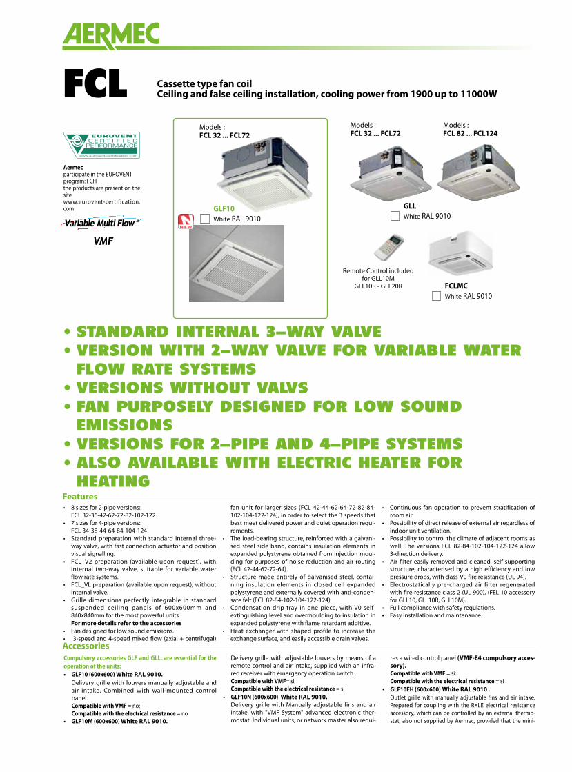
• FCLMC10 / FCLMC20 is a perimeter case in galvanised and painted sheet steel,
which is used when the fan coil is installed outside the suspended ceiling. It is used for aesthetics and protec-tion, therefore the technical features of the FCL remain unvaried.
For more details on the control panels and VMF system refer to the dedicated sheet
FCLMCWhite RAL 9010
FCL 32 34 36 38 42 44 62 64 72 82 84 102 104 122 124COMPULSARY GLL ACCESSORIES, ESSENTIAL FOR UNIT OPERATION: GLFI e GLLI and dedicated accessoriesGLF10 • • • • • • • • • - - - - - -
GLF10EH • • • • • • • • • - - - - - -RXLE • - • - • - • - • - - - - - -
GLF10M e GLF10N • • • • • • • • • - - - - - -VMF-E4 • • • • • • • • • - - - - - -TLF • • • • • • • • • - - - - - -RXLE • • • • • • • • • - - - - - -
GLL10 • • • • • • • • • - - - - - -
GLL10M • • • • • • • • • - - - - - -RXLE • • • • • • • • • - - - - - -
GLL10N • • • • • • • • • - - - - - -VMF-E4 • • • • • • • • • - - - - - -RXLE • • • • • • • • • - - - - - -
GLL10R • • • • • • • • • - - - - - -RXLE • - • - • - • - • - - - - - -
GLL20 - - - - - - - - - • • • • • •
GLL20N - - - - - - - - - • • • • • •VMF-E4 - - - - - - - - - • • • • • •RXLE20 - - - - - - - - - • • • • • •
GLL20R - - - - - - - - - • • • • • •RXLE20 - - - - - - - - - • - • - • -
Probes and accessories for control panelsPX-PX2-PX2C6* (1) • • • • • • • • • • • • • • •PXAE (1) • • • • • • • • • • • • • • •TPF (1) • • • • • • • • • • • • • • •WMT10 (1) • • • • • • • • • • • • • • •FMT10 (1) • • • • • • • • • • • • • • •TPFW (1) • • • • • • • • • • • • • • •SW3 (1) In combination with PXAESIT3 (1) In combination with TPFW or PXAE o PX2 or PX or PX2C6 WMT10SIT5 (1) In combination with TPFW or PXAESW4 (1) • • • • • • • • • • • • • • •
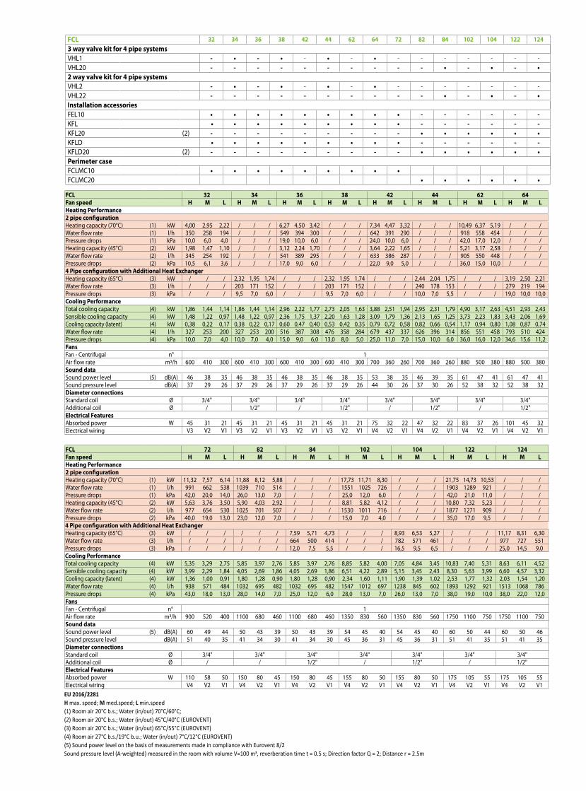
FCL 32 34 36 38 42 44 62 64Fan speed H M L H M L H M L H M L H M L H M L H M L H M LHeating Performance2 pipe configurationHeating capacity (70°C) (1) kW 4,00 2,95 2,22 / / / 6,27 4,50 3,42 / / / 7,34 4,47 3,32 / / / 10,49 6,37 5,19 / / /Water flow rate (1) l/h 350 258 194 / / / 549 394 300 / / / 642 391 290 / / / 918 558 454 / / /Pressure drops (1) kPa 10,0 6,0 4,0 / / / 19,0 10,0 6,0 / / / 24,0 10,0 6,0 / / / 42,0 17,0 12,0 / / /Heating capacity (45°C) (2) kW 1,98 1,47 1,10 / / / 3,12 2,24 1,70 / / / 3,64 2,22 1,65 / / / 5,21 3,17 2,58 / / /Water flow rate (2) l/h 345 254 192 / / / 541 389 295 / / / 633 386 287 / / / 905 550 448 / / /Pressure drops (2) kPa 10,5 6,1 3,6 / / / 17,0 9,0 6,0 / / / 22,0 9,0 5,0 / / / 36,0 15,0 10,0 / / /4 Pipe configuration with Additional Heat ExchangerHeating capacity (65°C) (3) kW / / / 2,32 1,95 1,74 / / / 2,32 1,95 1,74 / / / 2,44 2,04 1,75 / / / 3,19 2,50 2,21Water flow rate (3) l/h / / / 203 171 152 / / / 203 171 152 / / / 240 178 153 / / / 279 219 194Pressure drops (3) kPa / / / 9,5 7,0 6,0 / / / 9,5 7,0 6,0 / / / 10,0 7,0 5,5 / / / 19,0 10,0 10,0Cooling PerformanceTotal cooling capacity (4) kW 1,86 1,44 1,14 1,86 1,44 1,14 2,96 2,22 1,77 2,73 2,05 1,63 3,88 2,51 1,94 2,95 2,31 1,79 4,90 3,17 2,63 4,51 2,93 2,43Sensible cooling capacity (4) kW 1,48 1,22 0,97 1,48 1,22 0,97 2,36 1,75 1,37 2,20 1,63 1,28 3,09 1,79 1,36 2,13 1,65 1,25 3,73 2,23 1,83 3,43 2,06 1,69Cooling capacity (latent) (4) kW 0,38 0,22 0,17 0,38 0,22 0,17 0,60 0,47 0,40 0,53 0,42 0,35 0,79 0,72 0,58 0,82 0,66 0,54 1,17 0,94 0,80 1,08 0,87 0,74Water flow rate (4) l/h 327 253 200 327 253 200 516 387 308 476 358 284 679 437 337 626 396 314 856 551 458 793 510 424Pressure drops (4) kPa 10,0 7,0 4,0 10,0 7,0 4,0 15,0 9,0 6,0 13,0 8,0 5,0 25,0 11,0 7,0 15,0 10,0 6,0 36,0 16,0 12,0 34,6 15,6 11,2FansFan - Centrifugal n° 1Air flow rate m3/h 600 410 300 600 410 300 600 410 300 600 410 300 700 360 260 700 360 260 880 500 380 880 500 380Sound dataSound power level (5) dB(A) 46 38 35 46 38 35 46 38 35 46 38 35 53 38 35 46 39 35 61 47 41 61 47 41Sound pressure level dB(A) 37 29 26 37 29 26 37 29 26 37 29 26 44 30 26 37 30 26 52 38 32 52 38 32Diameter connectionsStandard coil Ø 3/4" 3/4" 3/4" 3/4" 3/4" 3/4" 3/4" 3/4"Additional coil Ø / 1/2" / 1/2" / 1/2" / 1/2"Electrical FeaturesAbsorbed power W 45 31 21 45 31 21 45 31 21 45 31 21 75 32 22 47 32 22 83 37 26 101 45 32Electrical wiring V3 V2 V1 V3 V2 V1 V3 V2 V1 V3 V2 V1 V4 V2 V1 V4 V2 V1 V4 V2 V1 V4 V2 V1
FCL 72 82 84 102 104 122 124Fan speed H M L H M L H M L H M L H M L H M L H M LHeating Performance2 pipe configurationHeating capacity (70°C) (1) kW 11,32 7,57 6,14 11,88 8,12 5,88 / / / 17,73 11,71 8,30 / / / 21,75 14,73 10,53 / / /Water flow rate (1) l/h 991 662 538 1039 710 514 / / / 1551 1025 726 / / / 1903 1289 921 / / /Pressure drops (1) kPa 42,0 20,0 14,0 26,0 13,0 7,0 / / / 25,0 12,0 6,0 / / / 42,0 21,0 11,0 / / /Heating capacity (45°C) (2) kW 5,63 3,76 3,50 5,90 4,03 2,92 / / / 8,81 5,82 4,12 / / / 10,80 7,32 5,23 / / /Water flow rate (2) l/h 977 654 530 1025 701 507 / / / 1530 1011 716 / / / 1877 1271 909 / / /Pressure drops (2) kPa 40,0 19,0 13,0 23,0 12,0 7,0 / / / 15,0 7,0 4,0 / / / 35,0 17,0 9,5 / / /4 Pipe configuration with Additional Heat ExchangerHeating capacity (65°C) (3) kW / / / / / / 7,59 5,71 4,73 / / / 8,93 6,53 5,27 / / / 11,17 8,31 6,30Water flow rate (3) l/h / / / / / / 664 500 414 / / / 782 571 461 / / / 977 727 551Pressure drops (3) kPa / / / / / / 12,0 7,5 5,5 / / / 16,5 9,5 6,5 / / / 25,0 14,5 9,0Cooling PerformanceTotal cooling capacity (4) kW 5,35 3,29 2,75 5,85 3,97 2,76 5,85 3,97 2,76 8,85 5,82 4,00 7,05 4,84 3,45 10,83 7,40 5,31 8,63 6,11 4,52Sensible cooling capacity (4) kW 3,99 2,29 1,84 4,05 2,69 1,86 4,05 2,69 1,86 6,51 4,22 2,89 5,15 3,45 2,43 8,30 5,63 3,99 6,60 4,57 3,32Cooling capacity (latent) (4) kW 1,36 1,00 0,91 1,80 1,28 0,90 1,80 1,28 0,90 2,34 1,60 1,11 1,90 1,39 1,02 2,53 1,77 1,32 2,03 1,54 1,20Water flow rate (4) l/h 938 571 484 1032 695 482 1032 695 482 1547 1012 697 1238 845 602 1893 1292 921 1513 1068 786Pressure drops (4) kPa 43,0 18,0 13,0 28,0 14,0 7,0 25,0 12,0 6,0 28,0 13,0 7,0 26,0 13,0 7,0 38,0 19,0 10,0 38,0 22,0 12,0FansFan - Centrifugal n° 1Air flow rate m3/h 900 520 400 1100 680 460 1100 680 460 1350 830 560 1350 830 560 1750 1100 750 1750 1100 750Sound dataSound power level (5) dB(A) 60 49 44 50 43 39 50 43 39 54 45 40 54 45 40 60 50 44 60 50 46Sound pressure level dB(A) 51 40 35 41 34 30 41 34 30 45 36 31 45 36 31 51 41 35 51 41 35Diameter connectionsStandard coil Ø 3/4" 3/4" 3/4" 3/4" 3/4" 3/4" 3/4"Additional coil Ø / / 1/2" / 1/2" / 1/2"Electrical FeaturesAbsorbed power W 110 58 50 150 80 45 150 80 45 155 80 50 155 80 50 175 105 55 175 105 55Electrical wiring V4 V2 V1 V4 V2 V1 V4 V2 V1 V4 V2 V1 V4 V2 V1 V4 V2 V1 V4 V2 V1EU 2016/2281 H max. speed; M med.speed; L min.speed(1) Room air 20°C b.s.; Water (in/out) 70°C/60°C; (2) Room air 20°C b.s.; Water (in/out) 45°C/40°C (EUROVENT)(3) Room air 20°C b.s.; Water (in/out) 65°C/55°C (EUROVENT)(4) Room air 27°C b.s./19°C b.u.; Water (in/out) 7°C/12°C (EUROVENT)(5) Sound power level on the basis of measurements made in compliance with Eurovent 8/2Sound pressure level (A-weighted) measured in the room with volume V=100 m3, reverberation time t = 0.5 s; Direction factor Q = 2; Distance r = 2.5m
FCL 32 34 36 38 42 44 62 64 72 82 84 102 104 122 1243 way valve kit for 4 pipe systemsVHL1 - • - • - • - • - - - - - - -VHL20 - - - - - - - - - - • - • - •2 way valve kit for 4 pipe systemsVHL2 - • - • - • - • - - - - - - -VHL22 - - - - - - - - - - • - • - •Installation accessoriesFEL10 • • • • • • • • • - - - - - -KFL • • • • • • • • • - - - - - -KFL20 (2) - - - - - - - - - • • • • • •KFLD • • • • • • • • • - - - - - -KFLD20 (2) - - - - - - - - - • • • • • •Perimeter caseFCLMC10 • • • • • • • • •FCLMC20 • • • • • •
Aermec S.p.A.Via Roma, 996 - 37040 Bevilacqua (VR) - ItaliaTel. 0442633111 - Telefax 044293577www.aermec.com
All specifications are subject to change without prior notice. Although every effort has been made to ensure accuracy, Aermec does not assume responsibility or liability for eventual errors or omissions.
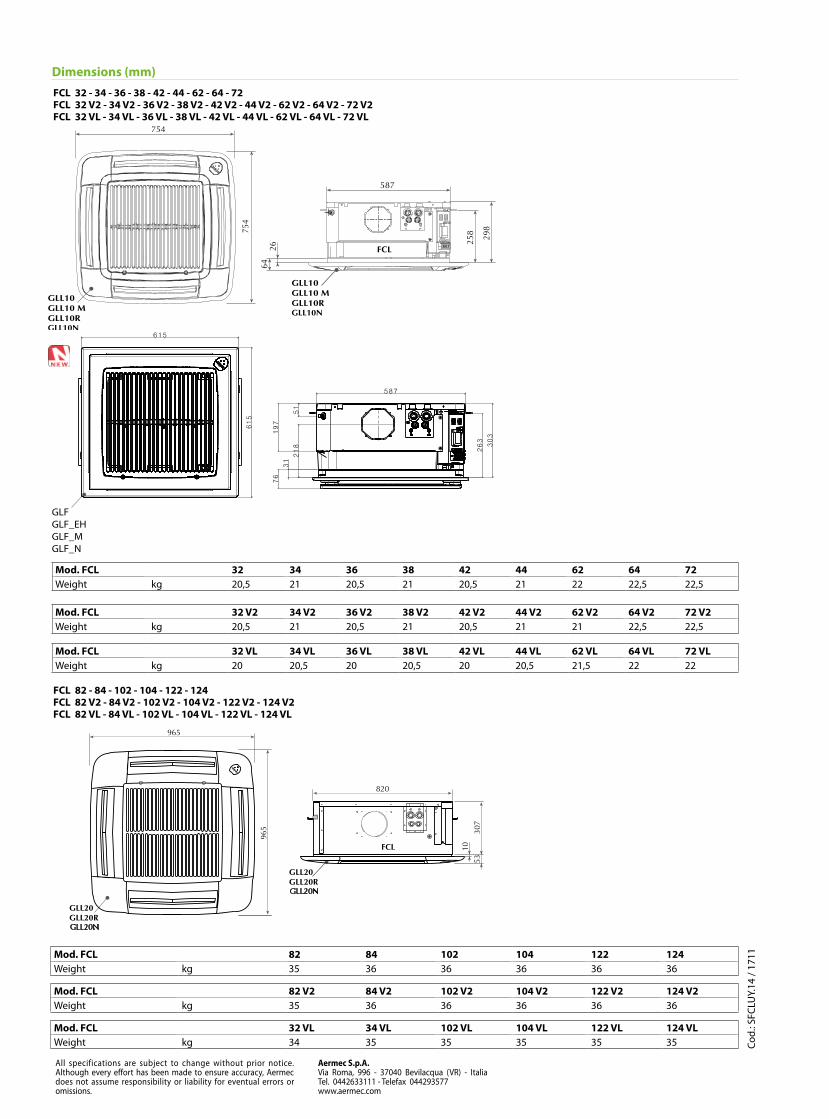
Dimensions (mm)
Cod.
: SFC
LUY.
14 /
1711
GLFGLF_EHGLF_MGLF_N
FCL 32 - 34 - 36 - 38 - 42 - 44 - 62 - 64 - 72FCL 32 V2 - 34 V2 - 36 V2 - 38 V2 - 42 V2 - 44 V2 - 62 V2 - 64 V2 - 72 V2FCL 32 VL - 34 VL - 36 VL - 38 VL - 42 VL - 44 VL - 62 VL - 64 VL - 72 VL
GLL20N
GLL20N
FCL 82 - 84 - 102 - 104 - 122 - 124 FCL 82 V2 - 84 V2 - 102 V2 - 104 V2 - 122 V2 - 124 V2 FCL 82 VL - 84 VL - 102 VL - 104 VL - 122 VL - 124 VL
Mod. FCL 32 34 36 38 42 44 62 64 72Weight kg 20,5 21 20,5 21 20,5 21 22 22,5 22,5
Mod. FCL 82 84 102 104 122 124Weight kg 35 36 36 36 36 36
Mod. FCL 32 V2 34 V2 36 V2 38 V2 42 V2 44 V2 62 V2 64 V2 72 V2Weight kg 20,5 21 20,5 21 20,5 21 21 22,5 22,5
Mod. FCL 82 V2 84 V2 102 V2 104 V2 122 V2 124 V2Weight kg 35 36 36 36 36 36
Mod. FCL 32 VL 34 VL 36 VL 38 VL 42 VL 44 VL 62 VL 64 VL 72 VLWeight kg 20 20,5 20 20,5 20 20,5 21,5 22 22
Mod. FCL 32 VL 34 VL 102 VL 104 VL 122 VL 124 VLWeight kg 34 35 35 35 35 35