Embed Size (px)
Citation preview

COMMUNICATIONS
F0057
FIRST ISSUE: 2009/06/25 Ref/Doc: 36719204-AA REVISION No: 1 34-42-61 TP Page 1
2009/07/09©THALES Communications S.A. This document and any data included are the property of THALES Communications. They cannot be reproduced, disclosed or utilised without the company's prior written approval.
COMPONENT MAINTENANCE MANUAL WITH
ILLUSTRATED PARTS LIST
RADAR ALTIMETER
AHV1600
P/N: 61778974AC

COMPONENT MAINTENANCE MANUAL
P/N 61778974AC
34-42-61 TP Page 2
2009/07/09©THALES Communications S.A. This document and any data included are the property of THALES Communications. They cannot be reproduced, disclosed or utilised without the company's prior written approval.
THIS PAGE INTENTIONALLY LEFT BLANK

COMPONENT MAINTENANCE MANUAL
P/N 61778974AC
34-42-61 ROR Page 1
2009/07/09©THALES Communications S.A. This document and any data included are the property of THALES Communications. They cannot be reproduced, disclosed or utilised without the company's prior written approval.
RECORD OF REVISIONS
REV ISSUE INSERTED
REV ISSUE INSERTED
No. DATE DATE BY
No. DATE DATE BY
1 2009/07/09 2009/07

COMPONENT MAINTENANCE MANUAL
P/N 61778974AC
34-42-61 ROR Page 2
2009/07/09©THALES Communications S.A. This document and any data included are the property of THALES Communications. They cannot be reproduced, disclosed or utilised without the company's prior written approval.
THIS PAGE INTENTIONALLY LEFT BLANK

COMPONENT MAINTENANCE MANUAL
P/N 61778974AC
34-42-61 RTR Page 1
2009/07/09©THALES Communications S.A. This document and any data included are the property of THALES Communications. They cannot be reproduced, disclosed or utilised without the company's prior written approval.
RECORD OF TEMPORARY REVISIONS
TEMP. REV. ISSUE INSERTED REMOVED
PAGE No.
No. DATE DATE BY DATE BY

COMPONENT MAINTENANCE MANUAL
P/N 61778974AC
34-42-61 RTR Page 2
2009/07/09©THALES Communications S.A. This document and any data included are the property of THALES Communications. They cannot be reproduced, disclosed or utilised without the company's prior written approval.
THIS PAGE INTENTIONALLY LEFT BLANK

COMPONENT MAINTENANCE MANUAL
P/N 61778974AC
34-42-61 SBL Page 1
2009/07/09©THALES Communications S.A. This document and any data included are the property of THALES Communications. They cannot be reproduced, disclosed or utilised without the company's prior written approval.
SERVICE BULLETIN LIST
SERVICE BULLETIN No.
REVISION No.
INCLUDED IN REVISION
DATE OF INCORPORATION TITLE

COMPONENT MAINTENANCE MANUAL
P/N 61778974AC
34-42-61 SBL Page 2
2009/07/09©THALES Communications S.A. This document and any data included are the property of THALES Communications. They cannot be reproduced, disclosed or utilised without the company's prior written approval.
THIS PAGE INTENTIONALLY LEFT BLANK

COMPONENT MAINTENANCE MANUAL
P/N 61778974AC
34-42-61 SILL Page 1
2009/07/09©THALES Communications S.A. This document and any data included are the property of THALES Communications. They cannot be reproduced, disclosed or utilised without the company's prior written approval.
SERVICE INFORMATION LETTER LIST
SERVICE INFORMATION
LETTER No.
INCLUDED IN
REVISION
DATE OF
INCORPORATION
TITLE

COMPONENT MAINTENANCE MANUAL
P/N 61778974AC
34-42-61 SILL Page 2
2009/07/09©THALES Communications S.A. This document and any data included are the property of THALES Communications. They cannot be reproduced, disclosed or utilised without the company's prior written approval.
THIS PAGE INTENTIONALLY LEFT BLANK

COMPONENT MAINTENANCE MANUAL
P/N 61778974AC
F indicates foldout page.
34-36-37 LEP Page 1
2009/07/09©THALES Communications S.A. This document and any data included are the property of THALES Communications. They cannot be reproduced, disclosed or utilised without the company's prior written approval.
LIST OF EFFECTIVE PAGES
SUBJECT PAGE DATE SUBJECT PAGE DATE Title Page 1 2009/07/09 Introduction 11 2009/07/09 2 Blank (continued) 12 2009/07/09 13 2009/07/09 Record of 1 2009/07/09 14 2009/07/09 Revisions 2 Blank 15 2009/07/09 16 2009/07/09 Record of 1 2009/07/09 17 2009/07/09 Temporary 2 Blank 18 2009/07/09 Revisions 19 2009/07/09 20 2009/07/09 Service 1 2009/07/09 Bulletin List 2 2009/07/09 Description 1 2009/07/09 and 2 2009/07/09 Service 1 2009/07/09 Operation 3 2009/07/09 Information 2 Blank 4 2009/07/09 Letter List 5 2009/07/09 6 2009/07/09 List of 1 2009/07/09 7 2009/07/09 Effective 2 2009/07/09 8 2009/07/09 Pages 3 2009/07/09 9 2009/07/09 4 Blank 10 2009/07/09 11 2009/07/09 Table of 1 2009/07/09 12 Blank Contents 2 2009/07/09 Testing and 1001 2009/07/09 Fault 1002 2009/07/09 Isolation 1003 2009/07/09 1004 2009/07/09 1005 2009/07/09 1006 2009/07/09 Introduction 1007 2009/07/09 1 2009/07/09 1008 2009/07/09 2 2009/07/09 1009 2009/07/09 3 2009/07/09 1010 2009/07/09 4 2009/07/09 1011 2009/07/09 5 2009/07/09 1012 2009/07/09 6 2009/07/09 1013 2009/07/09 7 2009/07/09 1014 2009/07/09 8 2009/07/09 1015 2009/07/09 9 2009/07/09 1016 2009/07/09 10 2009/07/09 1017 2009/07/09 1018 2009/07/09 1019 2009/07/09 1020 2009/07/09
COMPONENT MAINTENANCE MANUAL
P/N 61778974AC
F indicates foldout page.
34-42-61 LEP Page 2
2009/07/09©THALES Communications S.A. This document and any data included are the property of THALES Communications. They cannot be reproduced, disclosed or utilised without the company's prior written approval.
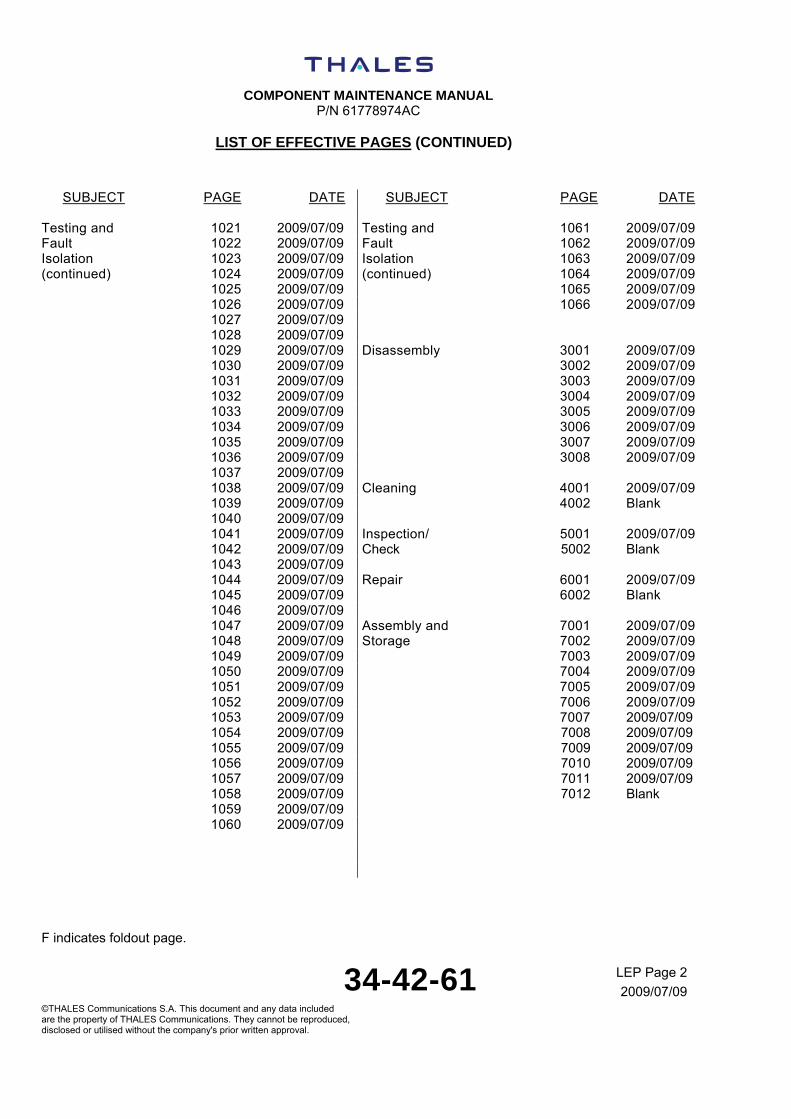
LIST OF EFFECTIVE PAGES (CONTINUED)
SUBJECT PAGE DATE SUBJECT PAGE DATE
Testing and 1021 2009/07/09 Testing and 1061 2009/07/09 Fault 1022 2009/07/09 Fault 1062 2009/07/09 Isolation 1023 2009/07/09 Isolation 1063 2009/07/09 (continued) 1024 2009/07/09 (continued) 1064 2009/07/09 1025 2009/07/09 1065 2009/07/09 1026 2009/07/09 1066 2009/07/09 1027 2009/07/09 1028 2009/07/09 1029 2009/07/09 Disassembly 3001 2009/07/09 1030 2009/07/09 3002 2009/07/09 1031 2009/07/09 3003 2009/07/09 1032 2009/07/09 3004 2009/07/09 1033 2009/07/09 3005 2009/07/09 1034 2009/07/09 3006 2009/07/09 1035 2009/07/09 3007 2009/07/09 1036 2009/07/09 3008 2009/07/09 1037 2009/07/09 1038 2009/07/09 Cleaning 4001 2009/07/09 1039 2009/07/09 4002 Blank 1040 2009/07/09 1041 2009/07/09 Inspection/ 5001 2009/07/09 1042 2009/07/09 Check 5002 Blank 1043 2009/07/09 1044 2009/07/09 Repair 6001 2009/07/09 1045 2009/07/09 6002 Blank 1046 2009/07/09 1047 2009/07/09 Assembly and 7001 2009/07/09 1048 2009/07/09 Storage 7002 2009/07/09 1049 2009/07/09 7003 2009/07/09 1050 2009/07/09 7004 2009/07/09 1051 2009/07/09 7005 2009/07/09 1052 2009/07/09 7006 2009/07/09 1053 2009/07/09 7007 2009/07/09 1054 2009/07/09 7008 2009/07/09 1055 2009/07/09 7009 2009/07/09 1056 2009/07/09 7010 2009/07/09 1057 2009/07/09 7011 2009/07/09 1058 2009/07/09 7012 Blank 1059 2009/07/09 1060 2009/07/09
COMPONENT MAINTENANCE MANUAL
P/N 61778974AC
F indicates foldout page.
34-36-37 LEP Page 3
2009/07/09©THALES Communications S.A. This document and any data included are the property of THALES Communications. They cannot be reproduced, disclosed or utilised without the company's prior written approval.
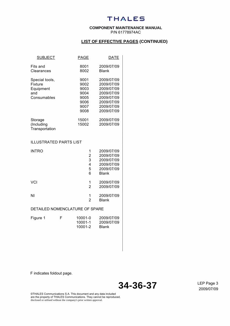
LIST OF EFFECTIVE PAGES (CONTINUED)
SUBJECT PAGE DATE
Fits and 8001 2009/07/09 Clearances 8002 Blank Special tools, 9001 2009/07/09 Fixture 9002 2009/07/09 Equipment 9003 2009/07/09 and 9004 2009/07/09 Consumables 9005 2009/07/09 9006 2009/07/09 9007 2009/07/09 9008 2009/07/09 Storage 15001 2009/07/09 (Including 15002 2009/07/09 Transportation ILLUSTRATED PARTS LIST INTRO 1 2009/07/09 2 2009/07/09 3 2009/07/09 4 2009/07/09 5 2009/07/09 6 Blank VCI 1 2009/07/09 2 2009/07/09 NI 1 2009/07/09 2 Blank DETAILED NOMENCLATURE OF SPARE Figure 1 F 10001-0 2009/07/09 10001-1 2009/07/09 10001-2 Blank

COMPONENT MAINTENANCE MANUAL
P/N 61778974AC
F indicates foldout page.
34-42-61 LEP Page 4
2009/07/09©THALES Communications S.A. This document and any data included are the property of THALES Communications. They cannot be reproduced, disclosed or utilised without the company's prior written approval.
THIS PAGE INTENTIONALLY LEFT BLANK

COMPONENT MAINTENANCE MANUAL
P/N 61778974AC
34-42-61 TOC Page 1
2009/07/09©THALES Communications S.A. This document and any data included are the property of THALES Communications. They cannot be reproduced, disclosed or utilised without the company's prior written approval.
TABLE OF CONTENTS
SUBJECT PAGE RECORD OF REVISIONS .................................................................................................................1 RECORD OF TEMPORARY REVISIONS..........................................................................................1 SERVICE BULLETIN LIST .................................................................................................................1 SERVICE INFORMATION LETTER LIST ..........................................................................................1 LIST OF EFFECTIVE PAGES............................................................................................................1 LIST OF EFFECTIVE PAGES (continued).........................................................................................2 LIST OF EFFECTIVE PAGES (continued).........................................................................................3 TABLE OF CONTENTS .....................................................................................................................1 INTRODUCTION ................................................................................................................................1
1. General ...................................................................................................................................1 2. General arrangement..............................................................................................................5 3. Maintenance task oriented support system task/subtask numbering .....................................8 4. Symbols and definitions ........................................................................................................17 5. List of abbreviations ..............................................................................................................20
DESCRIPTION AND OPERATION ....................................................................................................1 1. Description ..............................................................................................................................1 2. Operation ................................................................................................................................1
TESTING AND FAULT ISOLATION.............................................................................................1001 1. Introduction .......................................................................................................................1001 2. Measurement Tools Required...........................................................................................1002 3. Procedure .........................................................................................................................1002 4. AHV1600 transceiver - testing ..........................................................................................1017 5. Test report.........................................................................................................................1048 6. Fault isolation....................................................................................................................1060
DISASSEMBLY ............................................................................................................................3001 1. General .............................................................................................................................3001 2. Disassembly of DMB board ..............................................................................................3002 3. Disassembly of Power Supply STAGE .............................................................................3003 4. Disassembly of RADIO module ........................................................................................3004 5. Disassembly of HIRF module ...........................................................................................3005 6. Disassembly of MOTHER - I/O STAGE............................................................................3006 7. Disassembly of chassis.....................................................................................................3007
CLEANING ...................................................................................................................................4001 1. Cleaning of AHV1600 transceiver.....................................................................................4001
INSPECTION / CHECK ................................................................................................................5001 1. Inspection / Check of AHV1600 transceiver .....................................................................5001
REPAIR ........................................................................................................................................6001 1. Repair of AHV1600 transceiver ........................................................................................6001
ASSEMBLY ..................................................................................................................................7001 1. General .............................................................................................................................7001 2. Assembly of DMB board ...................................................................................................7002 3. Assembly of Power Supply STAGE ..................................................................................7003

COMPONENT MAINTENANCE MANUAL
P/N 61778974AC
34-42-61 TOC Page 2
2009/07/09©THALES Communications S.A. This document and any data included are the property of THALES Communications. They cannot be reproduced, disclosed or utilised without the company's prior written approval.
4. Assembly of RADIO module .............................................................................................7005 5. Assembly of HIRF module ................................................................................................7006 6. Assembly of MOTHER - I/O STAGE ................................................................................7009 7. Assembly of chassis .........................................................................................................7010
FITS AND CLEARANCES............................................................................................................8001 1. Tightening torques ............................................................................................................8001
SPECIAL TOOLS, FIXTURES, EQUIPMENT AND CONSUMABLES.........................................9001 1. Special Tool, Fixtures and Equipment ..............................................................................9001 2. Consumables Materials ....................................................................................................9007 3. 100 Feet and 120 Feet Delay Line Fabrication.................................................................9008
STORAGE (INCLUDING TRANSPORTATION) ........................................................................15001 1. Storage ........................................................................................................................... 15001
ILLUSTRATED PARTS LIST ............................................................................................................. 1 1. Introduction .............................................................................................................................1
COMPONENT MAINTENANCE MANUAL
P/N 61778974AC
34-42-61 INTRO Page 1
2009/07/09©THALES Communications S.A. This document and any data included are the property of THALES Communications. They cannot be reproduced, disclosed or utilised without the company's prior written approval.
INTRODUCTION
TASK 34-42-61-871-801-A01
1. GENERAL
A. Purpose of the Manual
The Component Maintenance Manual (CMM) conforms to ATA Specification No. 2200.
The CMM provides shop verified procedures that enable a technician to restore the component to its serviceable condition in the overhaul shop.
The Abbreviated Component Maintenance Manual (ACMM) is a brief version of the CMM, for simple components, which require periodic maintenance and/or testing.
The Manufacturer prepares the ACMM/CMM for each Repairable or Overhaulable unit.
THALES Publications use both metric and non−metric system of measurement. The system used in the original reference documents is given first, followed by the conversion into the other system in brackets.
B. Manual Breakdown Arrangement
The information contained in the CMM, has been divided into three main categories:
- Description and Operation (DO),
- Maintenance Procedure (MP),
- Illustrated Parts List (IPL).
The table below gives the identifications (Pageblock) used for the three categories of data.
COMPONENT MAINTENANCE MANUAL
P/N 61778974AC
34-42-61 INTRO Page 2
2009/07/09©THALES Communications S.A. This document and any data included are the property of THALES Communications. They cannot be reproduced, disclosed or utilised without the company's prior written approval.
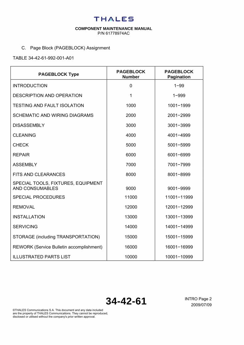
C. Page Block (PAGEBLOCK) Assignment
TABLE 34-42-61-992-001-A01
PAGEBLOCK Type PAGEBLOCK
Number PAGEBLOCK
Pagination
INTRODUCTION 0 1−99
DESCRIPTION AND OPERATION 1 1−999
TESTING AND FAULT ISOLATION 1000 1001−1999
SCHEMATIC AND WIRING DIAGRAMS 2000 2001−2999
DISASSEMBLY 3000 3001−3999
CLEANING 4000 4001−4999
CHECK 5000 5001−5999
REPAIR 6000 6001−6999
ASSEMBLY 7000 7001−7999
FITS AND CLEARANCES 8000 8001−8999
SPECIAL TOOLS, FIXTURES, EQUIPMENT AND CONSUMABLES 9000 9001−9999
SPECIAL PROCEDURES 11000 11001−11999
REMOVAL 12000 12001−12999
INSTALLATION 13000 13001−13999
SERVICING 14000 14001−14999
STORAGE (including TRANSPORTATION) 15000 15001−15999
REWORK (Service Bulletin accomplishment) 16000 16001−16999
ILLUSTRATED PARTS LIST 10000 10001−10999

COMPONENT MAINTENANCE MANUAL
P/N 61778974AC
34-42-61 INTRO Page 3
2009/07/09©THALES Communications S.A. This document and any data included are the property of THALES Communications. They cannot be reproduced, disclosed or utilised without the company's prior written approval.
(1) The Introduction explains the organization of the data in the CMM and the use of the data (DO and MP parts only)
For IPL part: see IPL INTRO (PAGEBLOCK 10000).
The introduction includes a glossary of non-standard abbreviations.
(2) Description and Operation
This pageblock gives general overall information.
It gives a mechanical and an electrical description.
It explains the configuration and the operation of the component.
It explains external connector interconnections in the component.
(3) Testing and Fault Isolation
This pageblock contains specific tests and procedures required to determine the condition of a component.
It includes fault isolation data.
(4) Schematic and Wiring Diagrams
This pageblock contains all schematic diagrams, wiring and interconnecting diagrams of cards, chassis wiring, modules, subassemblies.
(5) Disassembly
This pageblock gives step−by−step disassembly instructions in a logical sequence (in the order of IPL item numbers). It includes references to the figure item numbers from the IPL illustration(s) where applicable.
(6) Cleaning
This pageblock gives step−by−step description of the cleaning operations for the component and its parts.
(7) Check
This pageblock gives all the check procedures that are necessary during shop maintenance.
(8) Repair
This pageblock contains detailed repair procedures and specifications necessary to restore a worn or damaged part to serviceable condition.
(9) Assembly
This pageblock gives step−by−step assembly instructions in a logical sequence, references to the figure item numbers from the IPL illustration(s) where applicable.

COMPONENT MAINTENANCE MANUAL
P/N 61778974AC
34-42-61 INTRO Page 4
2009/07/09©THALES Communications S.A. This document and any data included are the property of THALES Communications. They cannot be reproduced, disclosed or utilised without the company's prior written approval.
(10) Fits and Clearances
This pageblock provides the fits and clearances data, in one or more tables, and torque tightening figures if applicable.
(11) Special Tools, Fixtures, Equipment and Consumables
This pageblock lists all special tools, fixtures, equipment and consumables necessary for maintenance actions given in the other pageblocks.
(12) Illustrated Parts List
This pageblock contains the complete list of all the parts of the component (For detailed description of the IPL, see IPL INTRO).
(13) Special Procedures
This pageblock contains tasks which are not part of the other pageblocks, but are necessary as a result of other maintenance tasks.
These tasks are self-contained repairs or preventive maintenance.
(14) Removal
Not applicable.
(15) Installation
Not applicable.
(16) Servicing
Not applicable.
(17) Storage
This pageblock contains requirements related to preparation for transportation, special handling, packaging, storage and preservation requirements of the component after assembly or test.
(18) Rework
Not applicable

COMPONENT MAINTENANCE MANUAL
P/N 61778974AC
34-42-61 INTRO Page 5
2009/07/09©THALES Communications S.A. This document and any data included are the property of THALES Communications. They cannot be reproduced, disclosed or utilised without the company's prior written approval.
TASK 34-42-61-879-801-A01
2. GENERAL ARRANGEMENT
A. PRELIMINARY PAGES AT THE BEGINNING OF THE CMM
(1) Title Page (TP)
(2) Record of Revisions (ROR)
(3) Transmittal Sheet (TS)
List page numbers of the revised pages and a brief description of the revision to affected pages.
Include insertion instruction for all supplied pages.
(4) Record of Temporary Revisions (RTR)
List the temporary revisions which shall be removed from the manual or which remain still effective.
(5) List of Service Bulletins (LSB)
List the Service Bulletins and the Service Information Letters which are applicable for the equipment.
(6) List of Effective Pages (LEP) (printed CMMs only)
List all effective pages for a given revision issue.
New pages are indicated by N, revised by R or deleted by D.
(7) Table of Contents (TOC)
List all major sub−divisions of each page block contained in the manual.
(8) List of Illustrations (LI)
List all illustrations contained in the manual.

COMPONENT MAINTENANCE MANUAL
P/N 61778974AC
34-42-61 INTRO Page 6
2009/07/09©THALES Communications S.A. This document and any data included are the property of THALES Communications. They cannot be reproduced, disclosed or utilised without the company's prior written approval.
B. INTRODUCTION (INTRO) STRUCTURE
(1) General
The introduction is broken down into Tasks.
This Task gives general information related to the CMM content.
(2) General arrangement
(3) Maintenance Task Oriented Support System (MTOSS) Task/Subtask numbering
This Task explains MTOSS Task/Subtask numbering system.
(4) Symbols and Definitions
(5) Glossary of Abbreviations
C. DESCRIPTION AND OPERATION (DO) STRUCTURE
(1) General
The Description and Operation is broken down into Tasks.
This Task gives general overall information.
(2) Description
This Task gives a mechanical and electrical description of the component.
(3) Operation
This Task explains the configuration and the operation of the component and its subassemblies.
D. MAINTENANCE PROCEDURE (MP) STRUCTURE
(1) General
The Maintenance Procedure is broken down into Tasks and Subtasks.
The MP is broken down into Tasks and Subtasks. Each Task is broken down into five Topics:
- Reason for the job,
- Job set-up information,
- Job set-up,
- Procedure,
- Close-up (if applicable).
COMPONENT MAINTENANCE MANUAL
P/N 61778974AC
34-42-61 INTRO Page 7
2009/07/09©THALES Communications S.A. This document and any data included are the property of THALES Communications. They cannot be reproduced, disclosed or utilised without the company's prior written approval.
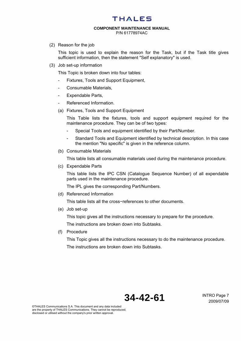
(2) Reason for the job
This topic is used to explain the reason for the Task, but if the Task title gives sufficient information, then the statement "Self explanatory" is used.
(3) Job set-up information
This Topic is broken down into four tables:
- Fixtures, Tools and Support Equipment,
- Consumable Materials,
- Expendable Parts,
- Referenced Information.
(a) Fixtures, Tools and Support Equipment
This Table lists the fixtures, tools and support equipment required for the maintenance procedure. They can be of two types:
- Special Tools and equipment identified by their Part/Number.
- Standard Tools and Equipment identified by technical description. In this case the mention "No specific" is given in the reference column.
(b) Consumable Materials
This table lists all consumable materials used during the maintenance procedure.
(c) Expendable Parts
This table lists the IPC CSN (Catalogue Sequence Number) of all expendable parts used in the maintenance procedure.
The IPL gives the corresponding Part/Numbers.
(d) Referenced Information
This table lists all the cross−references to other documents.
(e) Job set-up
This topic gives all the instructions necessary to prepare for the procedure.
The instructions are broken down into Subtasks.
(f) Procedure
This Topic gives all the instructions necessary to do the maintenance procedure.
The instructions are broken down into Subtasks.

COMPONENT MAINTENANCE MANUAL
P/N 61778974AC
34-42-61 INTRO Page 8
2009/07/09©THALES Communications S.A. This document and any data included are the property of THALES Communications. They cannot be reproduced, disclosed or utilised without the company's prior written approval.
(g) Close-up
This topic gives all the instructions necessary to put the component back to its initial configuration.
The instructions are broken down into Subtasks.
TASK 34-42-61-879-802-A01
3. MAINTENANCE TASK ORIENTED SUPPORT SYSTEM TASK/SUBTASK NUMBERING
A. GENERAL
The functional arrangement of data and the numbering system form the basis for the assignment of maintenance Task/Subtask numbers to each maintenance operation (Task) described in the CMM. Task/Subtask numbers are mainly for the use of the Data management and have no significance for the reader of the CMM. The Introduction (INTRO) and the Description and Operation (DO) are broken down into Tasks. The Maintenance Procedures (MP) is broken down into Tasks and Subtasks.
(1) TASK
A TASK is defined as:
- A maintenance work procedure, which contains a sequence of work steps, which may be organised into Subtasks.
- A block of data e.g. Description and Operation.
A table, an illustration or a multi−sheet illustration e.g. Figure x Sheets 1 through to 4 will all be part of one Task.
(2) SUBTASK
A SUBTASK is a single−skill work step or group of work steps within a Task, which provides detail of a significant part of the procedure. The completion of a SUBTASK must be possible in one location at one time.
COMPONENT MAINTENANCE MANUAL
P/N 61778974AC
34-42-61 INTRO Page 9
2009/07/09©THALES Communications S.A. This document and any data included are the property of THALES Communications. They cannot be reproduced, disclosed or utilised without the company's prior written approval.
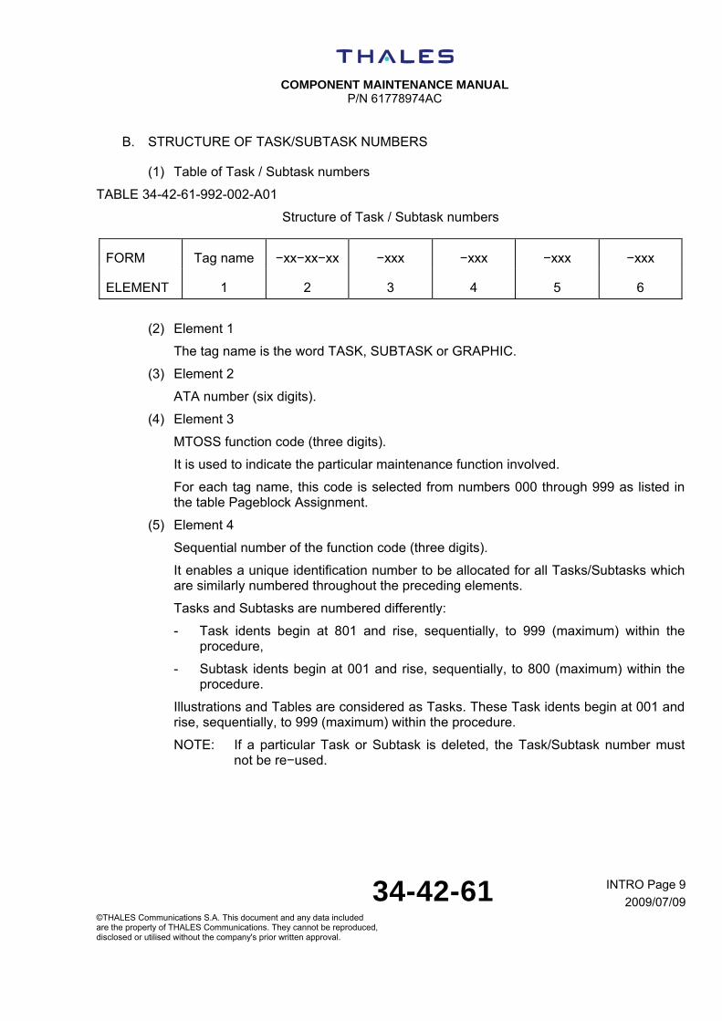
B. STRUCTURE OF TASK/SUBTASK NUMBERS
(1) Table of Task / Subtask numbers
TABLE 34-42-61-992-002-A01
Structure of Task / Subtask numbers
FORM Tag name −xx−xx−xx −xxx −xxx −xxx −xxx
ELEMENT 1 2 3 4 5 6
(2) Element 1
The tag name is the word TASK, SUBTASK or GRAPHIC.
(3) Element 2
ATA number (six digits).
(4) Element 3
MTOSS function code (three digits).
It is used to indicate the particular maintenance function involved.
For each tag name, this code is selected from numbers 000 through 999 as listed in the table Pageblock Assignment.
(5) Element 4
Sequential number of the function code (three digits).
It enables a unique identification number to be allocated for all Tasks/Subtasks which are similarly numbered throughout the preceding elements.
Tasks and Subtasks are numbered differently:
- Task idents begin at 801 and rise, sequentially, to 999 (maximum) within the procedure,
- Subtask idents begin at 001 and rise, sequentially, to 800 (maximum) within the procedure.
Illustrations and Tables are considered as Tasks. These Task idents begin at 001 and rise, sequentially, to 999 (maximum) within the procedure.
NOTE: If a particular Task or Subtask is deleted, the Task/Subtask number must not be re−used.
COMPONENT MAINTENANCE MANUAL
P/N 61778974AC
34-42-61 INTRO Page 10
2009/07/09©THALES Communications S.A. This document and any data included are the property of THALES Communications. They cannot be reproduced, disclosed or utilised without the company's prior written approval.
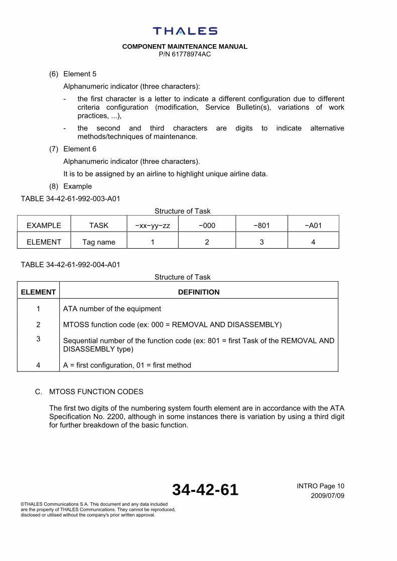
(6) Element 5
Alphanumeric indicator (three characters):
- the first character is a letter to indicate a different configuration due to different criteria configuration (modification, Service Bulletin(s), variations of work practices, ...),
- the second and third characters are digits to indicate alternative methods/techniques of maintenance.
(7) Element 6
Alphanumeric indicator (three characters).
It is to be assigned by an airline to highlight unique airline data.
(8) Example
TABLE 34-42-61-992-003-A01
Structure of Task
EXAMPLE TASK −xx−yy−zz −000 −801 −A01
ELEMENT Tag name 1 2 3 4
TABLE 34-42-61-992-004-A01
Structure of Task
ELEMENT DEFINITION
1 ATA number of the equipment
2 MTOSS function code (ex: 000 = REMOVAL AND DISASSEMBLY)
3 Sequential number of the function code (ex: 801 = first Task of the REMOVAL AND DISASSEMBLY type)
4 A = first configuration, 01 = first method
C. MTOSS FUNCTION CODES
The first two digits of the numbering system fourth element are in accordance with the ATA Specification No. 2200, although in some instances there is variation by using a third digit for further breakdown of the basic function.

COMPONENT MAINTENANCE MANUAL
P/N 61778974AC
34-42-61 INTRO Page 11
2009/07/09©THALES Communications S.A. This document and any data included are the property of THALES Communications. They cannot be reproduced, disclosed or utilised without the company's prior written approval.
TABLE 34-42-61-992-005-A01
Removal and Disassembly
000 Removal and Disassembly
010 Removal of complete component from transportation/work stand
020 Disassembly of unit into modular units
030 Disassembly of modules into subassemblies
040 Disassembly of subassemblies into individual parts
050 Removal of accessories/components not part of subject unit/opening panels for access
060 Disassembly of accessories into subassemblies
070 Disassembly of accessory into subassemblies into individual parts
080 Remove test equipment
090 Disassemble support equipment
TABLE 34-42-61-992-006-A01
Cleaning
100 Cleaning
110 Chemical cleaning/power flushing
120 Wet or dry abrasive cleaning
130 Ultrasonic cleaning
140 Mechanical/hand cleaning
150 Unassigned
160 Compressed air/miscellaneous hand cleaning or combination of procedures
170 Foam/water wash
180 Electro−mechanical test of solutions to identify materials
190 Unassigned

COMPONENT MAINTENANCE MANUAL
P/N 61778974AC
34-42-61 INTRO Page 12
2009/07/09©THALES Communications S.A. This document and any data included are the property of THALES Communications. They cannot be reproduced, disclosed or utilised without the company's prior written approval.
TABLE 34-42-61-992-007-A01
Inspection
200 Inspection
210 Visual examination to determine serviceability/unserviceability of unit
220 Visual/dimensional comparison with specifications/acceptance
230 Fluorescent penetrant NDT
240 Magnetic particle NDT
250 Eddy current NDT
260 X−ray NDT
270 Ultrasonic NDT
280 Any special inspection
290 Unassigned
TABLE 34-42-61-992-008-A01
Repair
300 Repair
310 Welding, brazing and soldering
320 Machining
330 Metallic coating removal/application
340 Plasma/flame spraying of coating
350 Repairs using hand tools, including necessary disassembly/assembly
360 Bonding and moulding
370 Heat treating
380 Surface treatment −painting, aluminizing, etc., including masking
390 Machine riveting and flaring
COMPONENT MAINTENANCE MANUAL
P/N 61778974AC
34-42-61 INTRO Page 13
2009/07/09©THALES Communications S.A. This document and any data included are the property of THALES Communications. They cannot be reproduced, disclosed or utilised without the company's prior written approval.
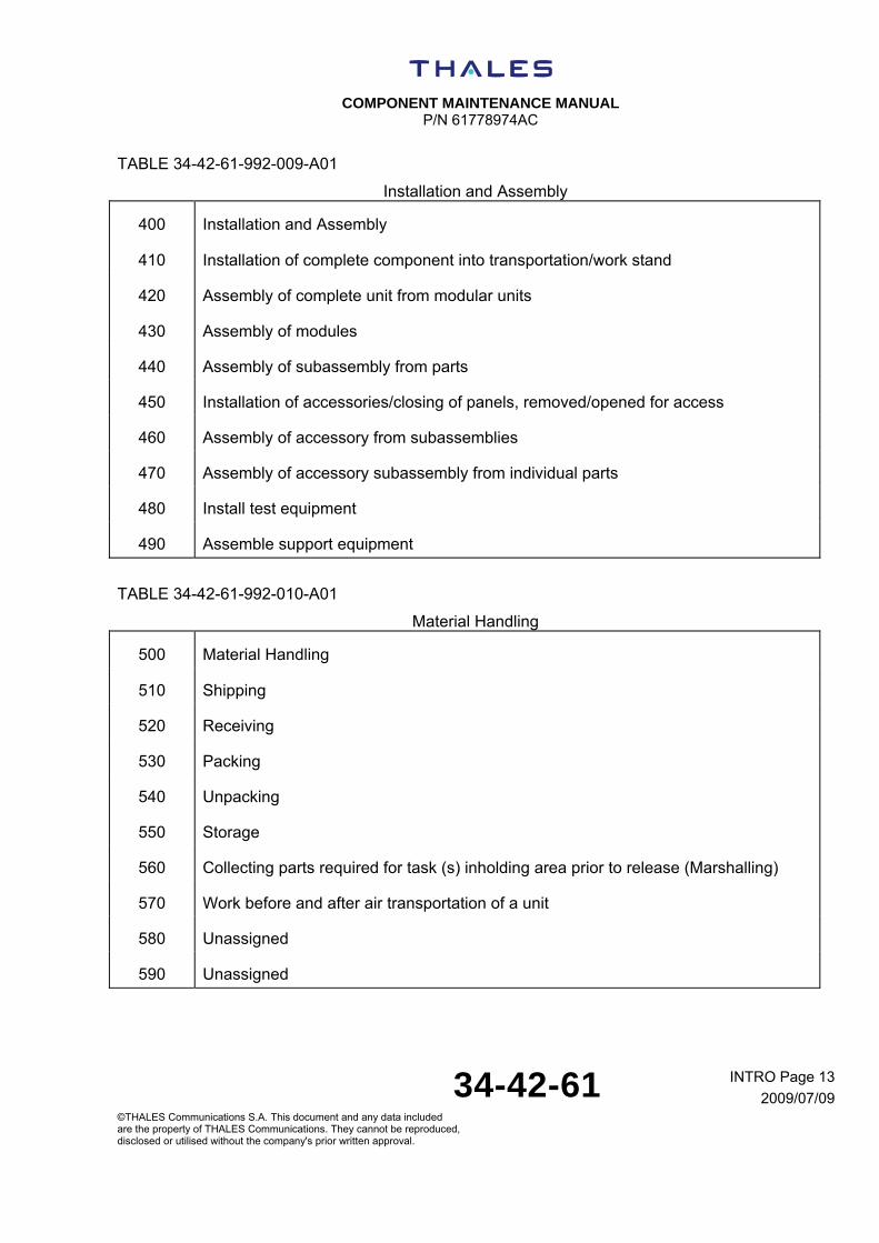
TABLE 34-42-61-992-009-A01
Installation and Assembly
400 Installation and Assembly
410 Installation of complete component into transportation/work stand
420 Assembly of complete unit from modular units
430 Assembly of modules
440 Assembly of subassembly from parts
450 Installation of accessories/closing of panels, removed/opened for access
460 Assembly of accessory from subassemblies
470 Assembly of accessory subassembly from individual parts
480 Install test equipment
490 Assemble support equipment
TABLE 34-42-61-992-010-A01
Material Handling
500 Material Handling
510 Shipping
520 Receiving
530 Packing
540 Unpacking
550 Storage
560 Collecting parts required for task (s) inholding area prior to release (Marshalling)
570 Work before and after air transportation of a unit
580 Unassigned
590 Unassigned

COMPONENT MAINTENANCE MANUAL
P/N 61778974AC
34-42-61 INTRO Page 14
2009/07/09©THALES Communications S.A. This document and any data included are the property of THALES Communications. They cannot be reproduced, disclosed or utilised without the company's prior written approval.
TABLE 34-42-61-992-011-A01
Servicing/Preserving/Lubricating
600 Servicing/Preserving/Lubricating
610 Servicing
620 Preserving
630 De−preserving
640 Lubricating
650 Unassigned
660 Unassigned
670 Unassigned
680 Unassigned
690 Unassigned
TABLE 34-42-61-992-012-A01
Testing/Checking
700 Testing/Checking
710 Oil flow measurement
720 Air flow measurement
730 Fuel flow measurement/functional check
740 Water flow measurement/functional check
750 Electrical functional checks/measurement of parameters to determine serviceability, may include fault isolation
760 Functional test of systems/performance check
770 Functional test of an accessory carte
780 Pressure check of system/component normally pressurized
790 Leak check
COMPONENT MAINTENANCE MANUAL
P/N 61778974AC
34-42-61 INTRO Page 15
2009/07/09©THALES Communications S.A. This document and any data included are the property of THALES Communications. They cannot be reproduced, disclosed or utilised without the company's prior written approval.
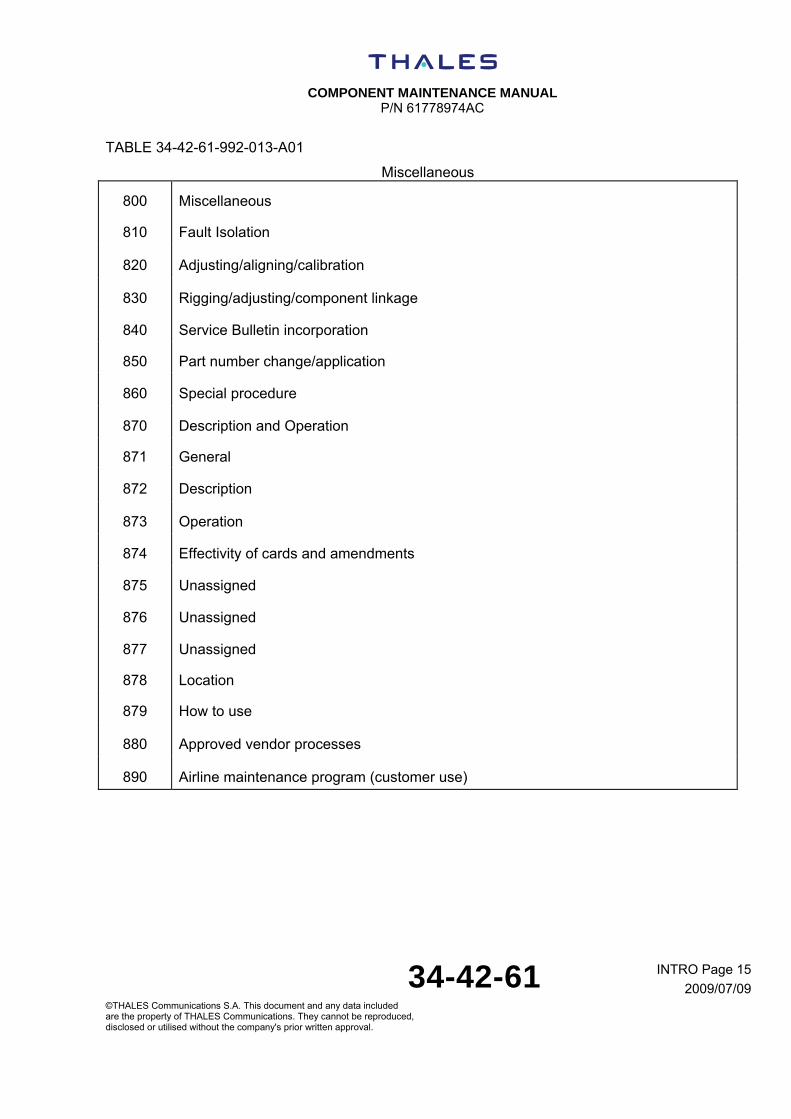
TABLE 34-42-61-992-013-A01
Miscellaneous
800 Miscellaneous
810 Fault Isolation
820 Adjusting/aligning/calibration
830 Rigging/adjusting/component linkage
840 Service Bulletin incorporation
850 Part number change/application
860 Special procedure
870 Description and Operation
871 General
872 Description
873 Operation
874 Effectivity of cards and amendments
875 Unassigned
876 Unassigned
877 Unassigned
878 Location
879 How to use
880 Approved vendor processes
890 Airline maintenance program (customer use)

COMPONENT MAINTENANCE MANUAL
P/N 61778974AC
34-42-61 INTRO Page 16
2009/07/09©THALES Communications S.A. This document and any data included are the property of THALES Communications. They cannot be reproduced, disclosed or utilised without the company's prior written approval.
D. RELATIONSHIP BETWEEN PAGEBLOCKS AND TASK/SUBTASK NUMBERS
TABLE 34-42-61-992-014-A01
Miscellaneous
PAGEBLOCK TASK number SUBTASK
number
Introduction 871, 879 None
Description and Operation 871, 872, 873 None
Testing and Fault Isolation 871, 700, 750 None
Schematic and Wiring Diagrams 878 None
Disassembly 000 020
Cleaning 100 160
Check 200 210, 220
Repair 300 350
Assembly 400 420
Fits and Clearances NA NA
Special Tools, Fixtures, Equipment and Consumables 940 None
Special Procedures 860, 300 None, 350
Removal NA NA
Installation NA NA
Servicing NA NA
Storage 550 530, 550
Rework NA NA
Illustrated Parts List 871, 874, 879, 950, 952
None
COMPONENT MAINTENANCE MANUAL
P/N 61778974AC
34-42-61 INTRO Page 17
2009/07/09©THALES Communications S.A. This document and any data included are the property of THALES Communications. They cannot be reproduced, disclosed or utilised without the company's prior written approval.
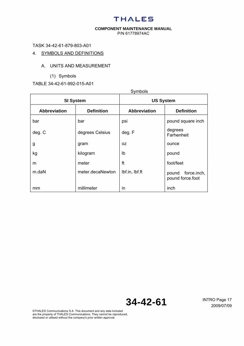
TASK 34-42-61-879-803-A01
4. SYMBOLS AND DEFINITIONS
A. UNITS AND MEASUREMENT
(1) Symbols
TABLE 34-42-61-992-015-A01
Symbols
SI System US System
Abbreviation Definition Abbreviation Definition
bar bar psi pound square inch
deg. C degrees Celsius deg. F degrees Farhenheit
g gram oz ounce
kg kilogram lb pound
m meter ft foot/feet
m.daN meter.decaNewton lbf.in, lbf.ft pound force.inch, pound force.foot
mm millimeter in inch

COMPONENT MAINTENANCE MANUAL
P/N 61778974AC
34-42-61 INTRO Page 18
2009/07/09©THALES Communications S.A. This document and any data included are the property of THALES Communications. They cannot be reproduced, disclosed or utilised without the company's prior written approval.
(2) Conversion table
TABLE 34-42-61-992-016-A01
Conversion
From SI system To US system
1 bar 14.5037 psi
1 g 0.0353 oz
1 kg 2.2046 lb
1 m 3.2809 ft
1 m.daN 88.4956 lbf.in, 7.3801 lbf.ft
1 mm 0.0394 in
Temperature conversion from degrees Celsius (deg.C) to degrees Fahrenheit (deg.F):
deg.F = (1.8 x deg.C) + 32.
B. REFERENCE DESIGNATOR INDEX (RDI)
The designation of a component (RDI) consist of:
- a code letter according to the following table,
- a sequential number.
TABLE 34-42-61-992-017-A01
Reference Designator Index
Type of component (RDI) Code letter
Battery BT
Capacitor C
Connector J or P
Coil L
Diode, zener diode,bridge diode D or CR
Fuse F
COMPONENT MAINTENANCE MANUAL
P/N 61778974AC
34-42-61 INTRO Page 19
2009/07/09©THALES Communications S.A. This document and any data included are the property of THALES Communications. They cannot be reproduced, disclosed or utilised without the company's prior written approval.
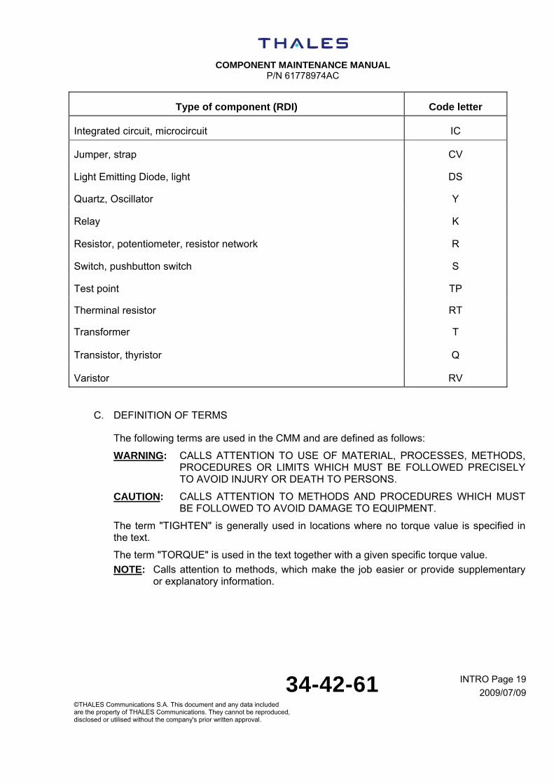
Type of component (RDI) Code letter
Integrated circuit, microcircuit IC
Jumper, strap CV
Light Emitting Diode, light DS
Quartz, Oscillator Y
Relay K
Resistor, potentiometer, resistor network R
Switch, pushbutton switch S
Test point TP
Therminal resistor RT
Transformer T
Transistor, thyristor Q
Varistor RV
C. DEFINITION OF TERMS
The following terms are used in the CMM and are defined as follows:
WARNING: CALLS ATTENTION TO USE OF MATERIAL, PROCESSES, METHODS, PROCEDURES OR LIMITS WHICH MUST BE FOLLOWED PRECISELY TO AVOID INJURY OR DEATH TO PERSONS.
CAUTION: CALLS ATTENTION TO METHODS AND PROCEDURES WHICH MUST BE FOLLOWED TO AVOID DAMAGE TO EQUIPMENT.
The term "TIGHTEN" is generally used in locations where no torque value is specified in the text.
The term "TORQUE" is used in the text together with a given specific torque value.
NOTE: Calls attention to methods, which make the job easier or provide supplementary or explanatory information.

COMPONENT MAINTENANCE MANUAL
P/N 61778974AC
34-42-61 INTRO Page 20
2009/07/09©THALES Communications S.A. This document and any data included are the property of THALES Communications. They cannot be reproduced, disclosed or utilised without the company's prior written approval.
TASK 34-42-61-871-802-A01
5. LIST OF ABBREVIATIONS
A. GENERAL
Abbreviations are used in the manual to make the text and illustrations shorter. These abbreviations and their definitions are given in the list that follows.
B. ABBREVIATIONS
A/D: Analog to Digital
AGC: Automatic Gain Control
ARINC: Aeronautical Radio INCorporated
BF: Beat Frequency
BIT: Built In Test
BITE: Built-in Test Equipment
DMB: Digital and Management Board
DSP: Digital Signal Processor
FW/CW: Frequency Modulated/Continuous Wave
GVA: Gain variable with the height ("Gain Variable avec l'Altitude")
HF: High Frequency
HIRF: High Intensity Radiated Field
I/O: Input/Output
LRU: Line Replaceable Unit
MNV: Non Volatile Memory (Mémoire Non Volatile)
MW: MicroWave
PLL: Phase Lock Loop
PS: Power Supply
RF: Radio Frequency
SRU: Shop Replaceable Unit
SMD: Surface Mount Device
C. SYMBOLS
Not applicable.

COMPONENT MAINTENANCE MANUAL
P/N 61778974AC
34-42-61 Page 1
2009/07/09©THALES Communications S.A. This document and any data included are the property of THALES Communications. They cannot be reproduced, disclosed or utilised without the company's prior written approval.
DESCRIPTION AND OPERATION
TASK 34-42-61-870-801-A01
1. DESCRIPTION
A. Principle
The purpose of a Radio Altimeter system is to provide the helicopter with accurate measurements of the minimal distance to the terrain (ground or sea). A Radio Altimeter is a kind of RADAR system, i.e. it uses the fact that the electromagnetic waves propagate through the air at a constant speed c , which is the speed of the light.
B. General
The AHV1600 Transceiver has 2 two mains sub-assembly:
- Digital Chassis,
- Radio Module.
The Digital Chassis:
- achieves the High Intensity Radiated Field (HIRF) protection, internal module interconnection, digital and management processor capacity and power supply distribution,
- provides the helicopter with the mechanical and electrical interfaces,
- provides the hardware support of the downloaded software’s.
The Radio Module:
- achieves the Radio Frequency (RF) signal emission, the Radio Frequency (RF) signal reception and the Beat Frequency (BF) signal extraction.
C. Physical description
The AHV1600 Transceiver is a metallic housing in the form of a parallelepiped protected by a black polyurethane painting.
It is made of a chassis with a front panel equipped with:
- an identification label,
- an amendments label,
- a main connector,
- two coaxial connectors:
one receive connector “RX” (J1),
one transmit connector “TX” (J2).
COMPONENT MAINTENANCE MANUAL
P/N 61778974AC
34-42-61 Page 2
2009/07/09©THALES Communications S.A. This document and any data included are the property of THALES Communications. They cannot be reproduced, disclosed or utilised without the company's prior written approval.
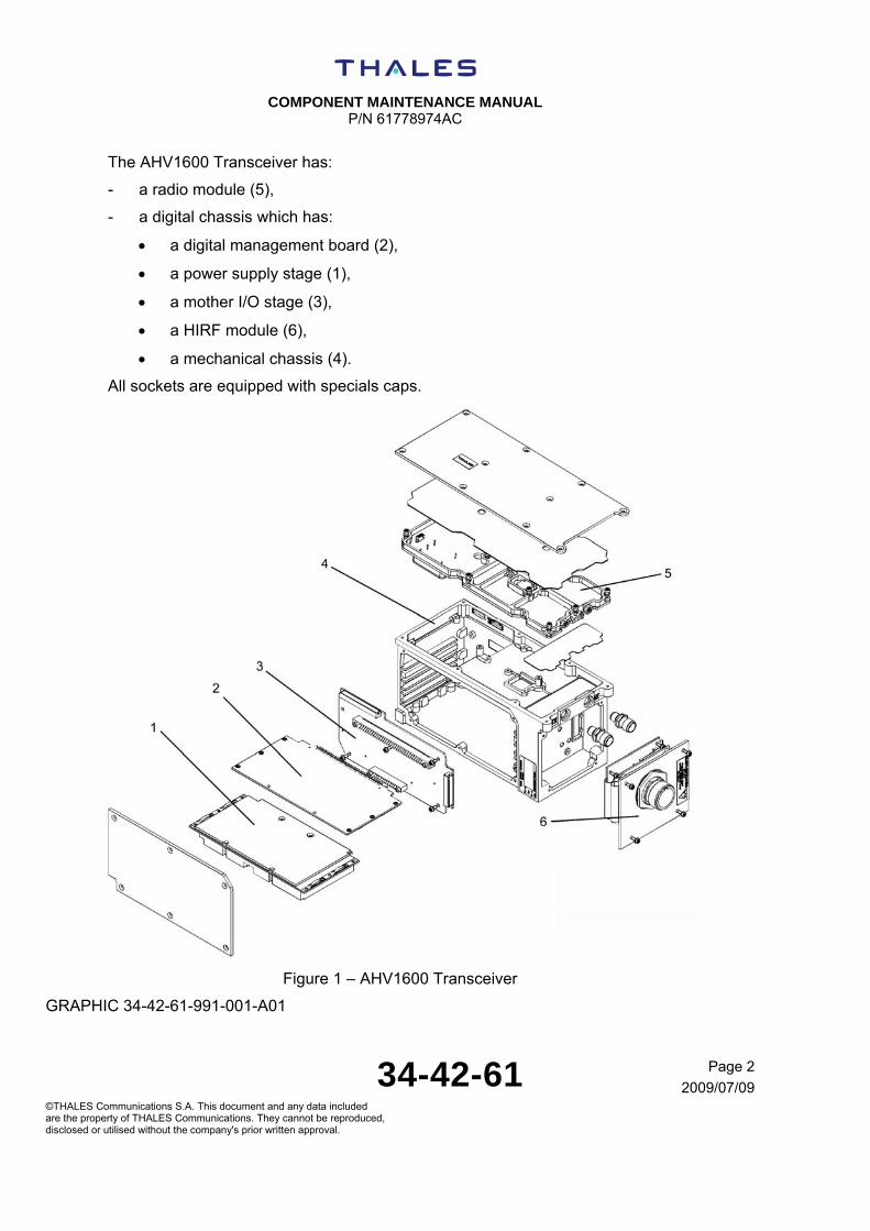
The AHV1600 Transceiver has:
- a radio module (5),
- a digital chassis which has:
a digital management board (2),
a power supply stage (1),
a mother I/O stage (3),
a HIRF module (6),
a mechanical chassis (4).
All sockets are equipped with specials caps.
Figure 1 – AHV1600 Transceiver
GRAPHIC 34-42-61-991-001-A01

COMPONENT MAINTENANCE MANUAL
P/N 61778974AC
34-42-61 Page 3
2009/07/09©THALES Communications S.A. This document and any data included are the property of THALES Communications. They cannot be reproduced, disclosed or utilised without the company's prior written approval.
(1) Main connector
TABLE 34-42-61-992-018-A01
CONTACT N° SIGNAL NAME
1 RA_EMIS_CMD
2 M_GND
3 TMS
4 CALIB_TEST
5 FCT_TST
6 TST_INH
7 CTZ_SEL2
8 TCK
9 TX429_HI_1
10 TX429_LO_1
11 SPP1
12 CTZ_SEL_P
13 TX429_HI_2
14 RX429_LO_2
15 MAINT
16 AID2
17 P28V_1
18 P28V_2
19 RET28V_2
20 AID_P
21 RS232_RX
22 RS232_TX
23 AID0
24 AID1
25 TDI
26 CTZ_SEL1
27 TDO
COMPONENT MAINTENANCE MANUAL
P/N 61778974AC
34-42-61 Page 4
2009/07/09©THALES Communications S.A. This document and any data included are the property of THALES Communications. They cannot be reproduced, disclosed or utilised without the company's prior written approval.
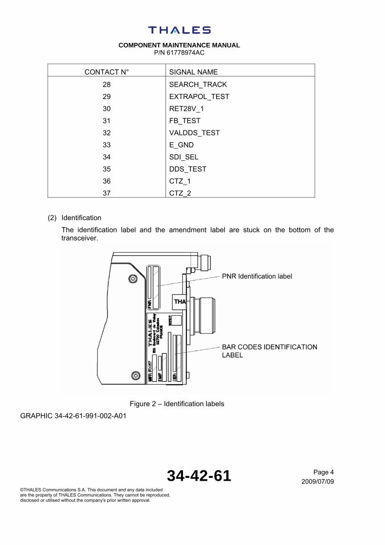
CONTACT N° SIGNAL NAME
28 SEARCH_TRACK
29 EXTRAPOL_TEST
30 RET28V_1
31 FB_TEST
32 VALDDS_TEST
33 E_GND
34 SDI_SEL
35 DDS_TEST
36 CTZ_1
37 CTZ_2
(2) Identification
The identification label and the amendment label are stuck on the bottom of the transceiver.
Figure 2 – Identification labels
GRAPHIC 34-42-61-991-002-A01

COMPONENT MAINTENANCE MANUAL
P/N 61778974AC
34-42-61 Page 5
2009/07/09©THALES Communications S.A. This document and any data included are the property of THALES Communications. They cannot be reproduced, disclosed or utilised without the company's prior written approval.
The specific label is stuck on the front panel.
Figure 3 – Specific and amendment label
GRAPHIC 34-42-61-991-003-A01
The identification labels have the information that follows:
Figure 4 – Identification labels
GRAPHIC 34-42-61-991-004-A01

COMPONENT MAINTENANCE MANUAL
P/N 61778974AC
34-42-61 Page 6
2009/07/09©THALES Communications S.A. This document and any data included are the property of THALES Communications. They cannot be reproduced, disclosed or utilised without the company's prior written approval.
The amendment plate has the information that follows:
Figure 5 – Amendment label
GRAPHIC 34-42-61-991-005-A01
(3) Characteristics
(a) Physical characteristics
- Dimensions: 190 x 90 x 95 mm (7.48 x 3.54 x 3.74 in)
- Weight < 2 kg (4.4 lb)
(b) Functional characteristics
- Transmission: FM/CW
- Frequency range: 4.2 GHz to 4.4 GHz
- Frequency Deviation: 123 MHz typical
- Height accuracy: +/- [2 ft + 2%(h)] at 2 σ
- Transmitted Power: + 18 dBm max typical
- Power supply: 28 Vdc
- Power consumption: 20 W max (18 W typical)
- RS-232 maintenance line
- Interface: ARINC429 low speed

C
OM
PO
NE
NT
MA
INT
EN
AN
CE
MA
NU
AL
P
/N 6
1778
974A
C
34
-42
-61
P
age
1
2009
/07/
09©
TH
ALE
S C
omm
unic
atio
ns S
.A.
Thi
s do
cum
ent
and
any
data
incl
uded
ar
e th
e pr
oper
ty o
f TH
ALE
S C
omm
unic
atio
ns.
The
y ca
nnot
be
repr
oduc
ed,
di
sclo
sed
or u
tilis
ed w
ithou
t th
e co
mpa
ny's
prio
r w
ritte
n ap
prov
al.
(4)
Env
ironm
enta
l con
ditio
ns
The
AH
V16
00 T
rans
ceiv
er i
s id
entif
ied
with
the
fol
low
ing
nece
ssa
ry i
nfor
mat
ion
rega
rdin
g th
e ap
prop
riate
cat
egor
y of
eac
h en
viro
nmen
tal
test
:
D
O16
0E C
at. [
(B4)
X]B
BB
[RG
]XW
FD
FS
ZZA
Z[Z
C][
HF
]M[(
A4G
33)(
A3J
33)]
XX
AX
D0-
160E
req
uire
men
t Se
ctio
n En
viro
nmen
tal c
ondi
tions
D
ocum
enta
ry e
vide
nces
or c
omm
ents
Tem
pera
ture
and
alti
tude
§4.5
.1
Gro
und
Sur
viva
l Lo
w
Tem
pera
ture
T
est
and
Sho
rt-T
ime
Ope
ratin
g Lo
w T
empe
ratu
re T
est
Equ
ipm
ent t
este
d to
cat
egor
y B
4
§4.5
.2 O
pera
ting
Low
Tem
pera
ture
Tes
t E
quip
men
t tes
ted
to c
ateg
ory
B4.
T
he
AH
V16
00
is
inte
nded
fo
r us
e w
ith
full
perf
orm
ance
s at
te
mpe
ratu
re u
p to
–40
°C.
§4.5
.3
Gro
und
Sur
viva
l H
igh
Tem
pera
ture
T
est
and
Sho
rt-t
ime
Ope
ratin
g H
igh
Tem
pera
ture
Tes
t E
quip
men
t tes
ted
to c
ateg
ory
B4.
§4.5
.4 O
pera
ting
Hig
h T
empe
ratu
re
Equ
ipm
ent t
este
d to
cat
egor
y B
4
The
AH
V16
00 T
rans
ceiv
er i
s in
tend
ed f
or u
se w
ith f
ull
perf
orm
ance
s at
tem
pera
ture
up
to +
70°C
.
§4.5
.5 In
-Flig
ht L
oss
of C
oolin
g T
est
Equ
ipm
ent i
dent
ified
as
Cat
egor
y X
, no
test
per
form
ed.
The
AH
V16
00 T
rans
ceiv
er is
inte
nded
for
use
with
no
cool
ing.
4
§4.6
.1 A
ltitu
de T
est
Equ
ipm
ent t
este
d to
Cat
egor
y B
4.

C
OM
PO
NE
NT
MA
INT
EN
AN
CE
MA
NU
AL
P
/N 6
1778
974A
C
34
-42
-61
Pag
e 2
2009
/07/
09
©T
HA
LES
Com
mun
icat
ions
S.A
. T
his
docu
men
t an
d an
y da
ta in
clud
ed
are
the
prop
erty
of T
HA
LES
Com
mun
icat
ions
. T
hey
cann
ot b
e re
prod
uced
,
disc
lose
d or
util
ised
with
out
the
com
pany
's p
rior
writ
ten
appr
oval
.
D0-
160E
req
uire
men
t Se
ctio
n En
viro
nmen
tal c
ondi
tions
D
ocum
enta
ry e
vide
nces
or c
omm
ents
§4.6
.2 D
ecom
pres
sion
Tes
t T
est n
ot a
pplic
able
acc
ordi
ng to
the
sele
cted
cat
egor
y §4
.6.3
Ove
rpre
ssur
e T
est
Tes
t not
app
licab
le a
ccor
ding
to th
e se
lect
ed c
ateg
ory
5 T
empe
ratu
re v
aria
tion
Equ
ipm
ent t
este
d to
Cat
egor
y B
. T
he A
HV
1600
Tra
nsce
iver
is in
tend
ed
for
use
with
ful
l per
form
ance
s at
te
mpe
ratu
re
varia
tions
be
twee
n -4
0°C
an
d +
70°C
op
erat
ing
tem
pera
ture
ext
rem
es.
6 H
umid
ity
Equ
ipm
ent t
este
d to
Cat
egor
y B
.
Ope
ratio
nal s
hock
s an
d cr
ash
safe
ty
§7.2
Ope
ratio
nal s
hock
s E
quip
men
t tes
ted
to C
ateg
ory
B.
§7.3
.1 C
rash
saf
ety
(impu
lse
test
) E
quip
men
t tes
ted
to C
ateg
ory
B.
7
§7.3
.1 C
rash
saf
ety
(sus
tain
ed te
st)
Equ
ipm
ent t
este
d to
Cat
egor
y B
. V
ibra
tion
§8.5
Sta
ndar
d vi
brat
ion
test
pro
cedu
re fi
xed
win
g ai
rcra
ft N
o te
st p
erfo
rmed
§8.6
Hig
h le
vel s
hort
dur
atio
n vi
brat
ion
test
pro
cedu
re
No
test
per
form
ed
§8.7
Rob
ust v
ibra
tion
Tes
t pro
cedu
re fi
xed
win
g ai
rcra
ft N
o te
st p
erfo
rmed
8
§8.8
Vib
ratio
n te
st fo
r he
licop
ters
E
quip
men
t te
sted
to
C
ateg
ory
R,
zone
2,
Cur
ve
G
(Hel
icop
ters
fr
eque
ncie
s at
f1=
20.5
Hz,
f2=
41.5
Hz,
f3=
f4=
0Hz)
9
Exp
losi
ve a
tmos
pher
e E
quip
men
t ide
ntifi
ed a
s C
ateg
ory
X, n
o te
st p
erfo
rmed
.
Wat
erpr
oofn
ess
§10.
3.1
Con
dens
ing
Wat
er P
roof
Tes
t T
est n
ot a
ppl
icab
le a
ccor
ding
to th
e se
lect
ed c
ateg
ory
10
§10.
3.2
Drip
pro
of T
est
Equ
ipm
ent t
este
d to
Cat
egor
y W
.

C
OM
PO
NE
NT
MA
INT
EN
AN
CE
MA
NU
AL
P
/N 6
1778
974A
C
34
-42
-61
P
age
3
2009
/07/
09©
TH
ALE
S C
omm
unic
atio
ns S
.A.
Thi
s do
cum
ent
and
any
data
incl
uded
ar
e th
e pr
oper
ty o
f TH
ALE
S C
omm
unic
atio
ns.
The
y ca
nnot
be
repr
oduc
ed,
di
sclo
sed
or u
tilis
ed w
ithou
t th
e co
mpa
ny's
prio
r w
ritte
n ap
prov
al.
D0-
160E
req
uire
men
t Se
ctio
n En
viro
nmen
tal c
ondi
tions
D
ocum
enta
ry e
vide
nces
or c
omm
ents
§10.
3.3
Spr
ay p
roof
Tes
t T
est n
ot a
pplic
able
acc
ordi
ng to
the
sele
cted
cat
egor
y.
§10.
3.3
Con
tinuo
us s
trea
m p
roof
Tes
t T
est n
ot a
pplic
able
acc
ord
ing
to th
e se
lect
ed c
ateg
ory.
F
luid
s su
scep
tibili
ty
§11.
4.1
Spr
ay T
est
Equ
ipm
ent c
ompl
iant
by
sim
ilarit
y to
Cat
egor
y F
T
he c
ompl
ianc
e of
the
AH
V16
00 T
rans
ceiv
er w
ith t
he s
pray
tes
t is
de
mon
stra
ted
by s
imila
rity
with
the
MIL
-ST
D-8
10F
met
hod
504
for
fluid
s.
List
of
fluid
con
tam
inan
t us
ed:
Avi
atio
n tu
rbin
e fu
el J
P-4
, JP
-5,
JP-8
, M
iner
al o
il ba
sed,
Pho
spha
te e
ster
bas
ed,
lubr
icat
ing
oils
(m
iner
al
base
d, e
ster
bas
ed s
ynth
etic
), s
olve
nts
and
clea
ning
flu
id (
isop
ropy
l A
lcoh
ol,
dena
ture
d A
lcoh
ol,
clea
ning
com
poun
d fo
r ai
rcra
ft su
rfac
es),
D
E-I
cing
flu
id
(eth
ylen
e G
lyco
l),
inse
ctic
ides
(d
ichl
oros
),
fire
extin
guis
hant
s (p
rote
in a
nd fl
uoro
prot
ein)
.
11
§11.
4.2
Imm
ersi
onT
est
No
test
per
form
ed.
San
d an
d du
st
§12.
4 D
ust t
est p
roce
dure
E
quip
men
t tes
ted
to C
ateg
ory
D.
12
§12.
5 S
and
test
pro
cedu
re
Tes
t not
app
licab
le a
ccor
ding
to th
e se
lect
ed c
ateg
ory.
13
Fun
gus
resi
stan
ce
Equ
ipm
ent c
ompl
iant
to C
ateg
ory
F.
14
Sal
t Fog
E
quip
men
t com
plia
nt to
Cat
egor
y S
. 15
M
agne
tic e
ffect
E
quip
men
t tes
ted
to C
ateg
ory
Z.
Pow
er in
put
The
A
HV
1600
T
rans
ceiv
er
is
inte
nded
fo
r us
e w
ith
a st
anda
rd
elec
tric
al 2
8VD
C p
ower
inpu
t 16
§16.
6.1.
1 N
orm
al o
pera
ting
cond
ition
s (d
c): v
olta
ge (
Ave
rage
Val
ue)
Equ
ipm
ent t
este
d to
Cat
egor
y Z
.

C
OM
PO
NE
NT
MA
INT
EN
AN
CE
MA
NU
AL
P
/N 6
1778
974A
C
34
-42
-61
Pag
e 4
2009
/07/
09
©T
HA
LES
Com
mun
icat
ions
S.A
. T
his
docu
men
t an
d an
y da
ta in
clud
ed
are
the
prop
erty
of T
HA
LES
Com
mun
icat
ions
. T
hey
cann
ot b
e re
prod
uced
,
disc
lose
d or
util
ised
with
out
the
com
pany
's p
rior
writ
ten
appr
oval
.
D0-
160E
req
uire
men
t Se
ctio
n En
viro
nmen
tal c
ondi
tions
D
ocum
enta
ry e
vide
nces
or c
omm
ents
§16.
6.1.
2 N
orm
al o
pera
ting
cond
ition
s (d
c): R
ippl
e V
olta
ge
Equ
ipm
ent c
ompl
iant
to C
ateg
ory
Z.
Not
e: A
s th
e R
ippl
e V
olta
ge r
equi
rem
ent
is a
ddre
ssed
by
§18.
3.1
Aud
io F
requ
ency
Con
duct
ed S
usce
ptib
ility
, th
e rip
ple
volta
ge t
est
has
not b
een
perf
orm
ed (
see
RT
CA
DO
160E
§16
.6.1
.2.b
not
e)
§16.
6.1.
3 N
orm
al
oper
atin
g co
nditi
ons
(dc)
: M
omen
tary
P
ower
In
terr
uptio
ns
Equ
ipm
ent t
este
d to
Cat
egor
y Z
.
TC
F
decl
ares
th
at
the
AH
V16
00
Tra
nsce
iver
is
ab
le
to
with
stan
d m
omen
tary
pow
er in
terr
uptio
n up
to
2ms
(Tes
t co
nditi
on 1
of
tabl
e 16
-3)
.
§16.
6.1.
4 N
orm
al o
pera
ting
cond
ition
(dc
): N
orm
al S
urge
Vol
tage
E
quip
men
t tes
ted
to C
ateg
ory
Z.
§16.
6.1.
5 N
orm
al
oper
atin
g co
nditi
on
(dc)
: E
ngin
e S
tart
ing
Und
er
Vol
tage
Ope
ratio
n
Equ
ipm
ent t
este
d to
Cat
egor
y Z
.
§16.
6.2.
1 A
bnor
mal
Ope
ratin
g C
ondi
tions
(dc
): V
olta
ge S
tead
y S
tate
E
quip
men
t tes
ted
to C
ateg
ory
Z.
§16.
6.2.
2 A
bnor
mal
O
pera
ting
Con
ditio
ns
(dc)
: Lo
w
Vol
tage
C
ondi
tions
Tes
t not
app
licab
le a
ccor
ding
to th
e se
lect
ed c
ateg
ory.
§16.
6.2.
3 A
bnor
mal
O
pera
ting
Con
ditio
ns
(dc)
: M
omen
tary
U
nder
volta
ge O
pera
tion
Equ
ipm
ent t
este
d to
Cat
egor
y Z
.
§16.
6.2.
4 A
bnor
mal
O
pera
ting
Con
ditio
ns
(dc)
: A
bnor
mal
S
urge
V
olta
ge
Equ
ipm
ent t
este
d to
Cat
egor
y Z
.
17
Vol
tage
spi
ke
Equ
ipm
ent t
este
d to
Cat
egor
y A
.
18
Aud
io fr
eque
ncy
cond
ucte
d su
scep
tibili
ty –
pow
er in
puts
C
OM
PO
NE
NT
MA
INT
EN
AN
CE
MA
NU
AL
P
/N 6
1778
974A
C
34
-42
-61
P
age
5
2009
/07/
09©
TH
ALE
S C
omm
unic
atio
ns S
.A.
Thi
s do
cum
ent
and
any
data
incl
uded
ar
e th
e pr
oper
ty o
f TH
ALE
S C
omm
unic
atio
ns.
The
y ca
nnot
be
repr
oduc
ed,
di
sclo
sed
or u
tilis
ed w
ithou
t th
e co
mpa
ny's
prio
r w
ritte
n ap
prov
al.
D0-
160E
req
uire
men
t Se
ctio
n En
viro
nmen
tal c
ondi
tions
D
ocum
enta
ry e
vide
nces
or c
omm
ents
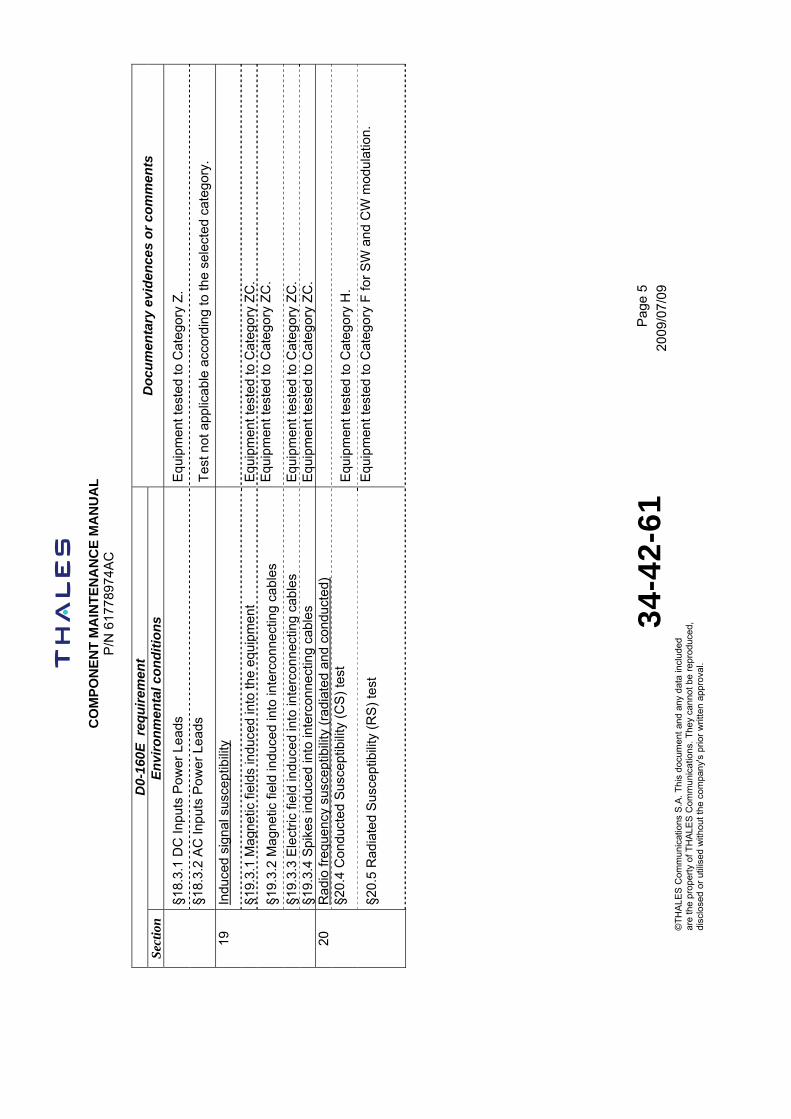
§18.
3.1
DC
Inpu
ts P
ower
Lea
ds
Equ
ipm
ent t
este
d to
Cat
egor
y Z
.
§18.
3.2
AC
Inpu
ts P
ower
Lea
ds
Tes
t not
app
licab
le a
ccor
ding
to th
e se
lect
ed c
ateg
ory.
Indu
ced
sign
al s
usce
ptib
ility
§19.
3.1
Mag
netic
fiel
ds in
duce
d in
to th
e eq
uipm
ent
Equ
ipm
ent t
este
d to
Cat
egor
y Z
C.
§19.
3.2
Mag
netic
fiel
d in
duce
d in
to in
terc
onne
ctin
g ca
bles
E
quip
men
t tes
ted
to C
ateg
ory
ZC
.
§19.
3.3
Ele
ctric
fiel
d in
duce
d in
to in
terc
onne
ctin
g ca
bles
E
quip
men
t tes
ted
to C
ateg
ory
ZC
.
19
§19.
3.4
Spi
kes
indu
ced
into
inte
rcon
nect
ing
cabl
es
Equ
ipm
ent t
este
d to
Cat
egor
y Z
C.
Rad
io fr
eque
ncy
susc
eptib
ility
(ra
diat
ed a
nd c
ondu
cted
)
§20.
4 C
ondu
cted
Sus
cept
ibili
ty (
CS
) te
st
Equ
ipm
ent t
este
d to
Cat
egor
y H
.
20
§20.
5 R
adia
ted
Sus
cept
ibili
ty (
RS
) te
st
Equ
ipm
ent t
este
d to
Cat
egor
y F
for
SW
and
CW
mod
ulat
ion.
C
OM
PO
NE
NT
MA
INT
EN
AN
CE
MA
NU
AL
P
/N 6
1778
974A
C
34
-42
-61
Pag
e 6
2009
/07/
09
©T
HA
LES
Com
mun
icat
ions
S.A
. T
his
docu
men
t an
d an
y da
ta in
clud
ed
are
the
prop
erty
of T
HA
LES
Com
mun
icat
ions
. T
hey
cann
ot b
e re
prod
uced
,
disc
lose
d or
util
ised
with
out
the
com
pany
's p
rior
writ
ten
appr
oval
.
D0-
160E
req
uire
men
t Se
ctio
n En
viro
nmen
tal c
ondi
tions
D
ocum
enta
ry e
vide
nces
or c
omm
ents
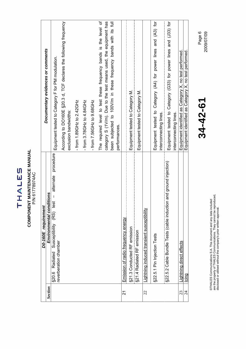
§20.
6 R
adia
ted
Sus
cept
ibili
ty
(RS
) te
st
– al
tern
ate
proc
edur
e re
verb
erat
ion
cham
ber
Equ
ipm
ent t
este
d to
Cat
egor
y F
for
PM
mod
ulat
ion.
Acc
ordi
ng t
o D
O16
0E §
20.3
d,
TC
F d
ecla
res
the
follo
win
g fr
eque
ncy
excl
usio
n ba
ndw
idth
s:
- fr
om 1
.89G
Hz
to 2
.42G
Hz
- fr
om 3
.78G
Hz
to 4
.84G
Hz
- fr
om 7
.56G
Hz
to 9
.68G
Hz
The
re
quire
d le
vel
to
test
th
ese
freq
uenc
y ba
nds
is
the
leve
l of
ca
tego
ry S
(1V
/m).
Due
to
the
test
mea
ns u
sed,
the
equ
ipm
ent
has
been
su
bjec
ted
to
100V
/m
in
thes
e fr
eque
ncy
band
s w
ith
its
full
perf
orm
ance
s.
Em
issi
on o
f rad
io fr
eque
ncy
ener
gy
§21.
3 C
ondu
cted
RF
em
issi
on
Equ
ipm
ent t
este
d to
Cat
egor
y M
.
21
§21.
4 R
adia
ted
RF
em
issi
on
Equ
ipm
ent t
este
d to
Cat
egor
y M
.
Ligh
tnin
g in
duce
d tr
ansi
ent s
usce
ptib
ility
§22.
5.1
Pin
Inje
ctio
n T
ests
E
quip
men
t te
sted
to
C
ateg
ory
(A4)
fo
r po
wer
lin
es
and
(A3)
fo
r in
terc
onne
ctin
g lin
es.
22
§22.
5.2
Cab
le B
undl
e T
ests
(ca
ble
indu
ctio
n an
d gr
ound
inje
ctio
n)
Equ
ipm
ent
test
ed t
o C
ateg
ory
(G33
) fo
r po
wer
lin
es a
nd (
J33)
for
in
terc
onne
ctin
g lin
es.
23
Ligh
tnin
g di
rect
effe
cts
Equ
ipm
ent i
dent
ified
as
Cat
egor
y X
, no
test
per
form
ed.
24
Icin
g
Equ
ipm
ent i
dent
ified
as
Cat
egor
y X
, no
test
per
form
ed.
C
OM
PO
NE
NT
MA
INT
EN
AN
CE
MA
NU
AL
P
/N 6
1778
974A
C
34
-42
-61
P
age
7
2009
/07/
09©
TH
ALE
S C
omm
unic
atio
ns S
.A.
Thi
s do
cum
ent
and
any
data
incl
uded
ar
e th
e pr
oper
ty o
f TH
ALE
S C
omm
unic
atio
ns.
The
y ca
nnot
be
repr
oduc
ed,
di
sclo
sed
or u
tilis
ed w
ithou
t th
e co
mpa
ny's
prio
r w
ritte
n ap
prov
al.
D0-
160E
req
uire
men
t Se
ctio
n En
viro
nmen
tal c
ondi
tions
D
ocum
enta
ry e
vide
nces
or c
omm
ents
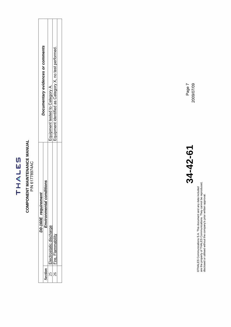
25
Ele
ctro
stat
ic d
isch
arge
E
quip
men
t tes
ted
to C
ateg
ory
A.
26
Fire
, Fla
mm
abili
ty
Equ
ipm
ent i
dent
ified
as
Cat
egor
y X
, no
test
per
form
ed.


COMPONENT MAINTENANCE MANUAL
P/N 61778974AC
34-42-61 Page 1
2009/07/09©THALES Communications S.A. This document and any data included are the property of THALES Communications. They cannot be reproduced, disclosed or utilised without the company's prior written approval.
TASK 34-42-61-870-802-A01
2. OPERATION
A. Functional architecture of the AHV1600
The general architecture of the AHV1600 is the following:
MicroProcessor
PROM
RAM
Peripheral
Digital signalprocessor
ADC
HF Ampli
ReceiveFilter
TransmitFilter
PWM
BF Ampli
4.2/4.4GHz
VCO
PhaseLoop
PWM
Delay
Synthetiser
TCXO
PowerControl
Generator
VideoControl
GVAAmplifier
Power management control
HF Ampli
BUS
Sawtoothmodulation
control
128 %
Power supply stage
+5V +15V -15V
Power central
Arinc Drivers
Discretes
EEPROM
PIN Prog
Mother_IO board
Radio module Digital/management board
HIRF module
FPGA Radio
SRU RADIO
SRU DIGITAL CHASSIS
Figure 6 – General architecture of the AHV1600
GRAPHIC 34-42-61-991-006-A01
The AHV1600 transceiver has:
- Radio module: regroups the microwave transmitter and receiver, and the analog treatment of the beating frequency. The Digital Management board commands and monitors the radio module. It provides the Digital Management board with the beating frequency signal. It receives its power from the Power Supply (PS) stage. The Field Programmable Gate Array (FPGA) commands the radio module.
- Digital Management board: commands and monitors the transmission function of radio module and the height output function as well. It computes the height out of the beating frequency and the modulation shape of the effectively transmit frequency.
- Power Supply (PS) stage: provides the system with its needed power and Digital Management board with a status containing the results of power supply stage internal monitoring.
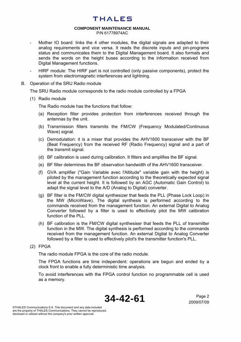
COMPONENT MAINTENANCE MANUAL
P/N 61778974AC
34-42-61 Page 2
2009/07/09©THALES Communications S.A. This document and any data included are the property of THALES Communications. They cannot be reproduced, disclosed or utilised without the company's prior written approval.
- Mother IO board: links the 4 other modules, the digital signals are adapted to their analog requirements and vice versa. It reads the discrete inputs and pin-programs status and communicates them to the Digital Management board. It also formats and sends the words on the height buses according to the information received from Digital Management functions.
- HIRF module: The HIRF part is not controlled (only passive components), protect the system from electromagnetic interferences and lightning.
B. Operation of the SRU Radio module
The SRU Radio module corresponds to the radio module controlled by a FPGA
(1) Radio module
The Radio module has the functions that follow:
(a) Reception filter provides protection from interferences received through the antennas by the unit.
(b) Transmission filters transmits the FM/CW (Frequency Modulated/Continuous Wave) signal.
(c) Demodulation: it is a mixer that provides the AHV1600 transceiver with the BF (Beat Frequency) from the received RF (Radio Frequency) signal and a part of the transmit signal.
(d) BF calibration is used during calibration. It filters and amplifies the BF signal.
(e) BF filter determines the BF observation bandwidth of the AHV1600 transceiver.
(f) GVA amplifier ("Gain Variable avec l'Altitude" variable gain with the height) is piloted by the management function according to the theoretically expected signal level at the current height. It is followed by an AGC (Automatic Gain Control) to adapt the signal level to the A/D (Analog to Digital) converter.
(g) BF filter is the FM/CW digital synthesizer that feeds the PLL (Phase Lock Loop) in the MW (MicroWave). The digital synthesis is performed according to the commands received from the management function. An external Digital to Analog Converter followed by a filter is used to effectively pilot the MW calibration function of the PLL.
(h) BF calibration is the FM/CW digital synthesiser that feeds the PLL of transmitter function in the MW. The digital synthesis is performed according to the commands received from the management function. An external Digital to Analog Converter followed by a filter is used to effectively pilot's the transmitter function's PLL.
(2) FPGA
The radio module FPGA is the core of the radio module.
The FPGA functions are time independent: operations are begun and ended by a clock front to enable a fully deterministic time analysis.
To avoid interferences with the FPGA control function no programmable cell is used as a memory.
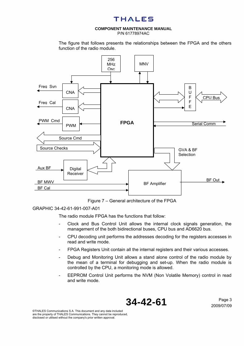
COMPONENT MAINTENANCE MANUAL
P/N 61778974AC
34-42-61 Page 3
2009/07/09©THALES Communications S.A. This document and any data included are the property of THALES Communications. They cannot be reproduced, disclosed or utilised without the company's prior written approval.
The figure that follows presents the relationships between the FPGA and the others function of the radio module.
Figure 7 – General architecture of the FPGA
GRAPHIC 34-42-61-991-007-A01
The radio module FPGA has the functions that follow:
- Clock and Bus Control Unit allows the internal clock signals generation, the management of the both bidirectional buses, CPU bus and AD6620 bus.
- CPU decoding unit performs the addresses decoding for the registers accesses in read and write mode.
- FPGA Registers Unit contain all the internal registers and their various accesses.
- Debug and Monitoring Unit allows a stand alone control of the radio module by the mean of a terminal for debugging and set-up. When the radio module is controlled by the CPU, a monitoring mode is allowed.
- EEPROM Control Unit performs the NVM (Non Volatile Memory) control in read and write mode.
Aux BF
BF MWV
BF Cal
BF Out
PWM Cmd
Freq Cal
Freq Syn
Serial Comm
MNV
256 MHz Osc
B U F F E
CPU Bus
CNA
CNA
PWM
Source Checks
Digital
Receiver
BF Amplifier
FPGA
Source Cmd
GVA & BF Selection
COMPONENT MAINTENANCE MANUAL
P/N 61778974AC
34-42-61 Page 4
2009/07/09©THALES Communications S.A. This document and any data included are the property of THALES Communications. They cannot be reproduced, disclosed or utilised without the company's prior written approval.
- Frequency Synthesis Unit includes:
Reference frequency Freq_Syn samples generation
Delayed frequency Freq_Cal samples generation
Sawtooth modulation control providing the logical signals reflecting the modulation duration and BF samples validation
Modulation duration computation
- Transmit and Receive Configuration Unit controls the transmission sequencing in the different modes, the signals to the microwave part.
- PWM Control Unit generates the Power Management voltage
- GVA Control Unit controls the GVA A/D convertor.
C. Operation of the SRU Digital chassis
The SRU Digital chassis has the modules that follow:
- Mechanical chassis,
- Mother I/O stage,
- HIRF module,
- Power Supply (PS) stage,
- Digital Management board.
(1) Mechanical chassis
It is the mechanical host of the AHV1600 transceiver.
(2) Mother I/O board
It has the functions that follow:
- Discrete inputs/outputs, pin programming
- Height buses.
- The I/O interface function reads the discrete inputs and pin-programs status and communicates them to the Digital Management board. It also formats and sends the words on the height buses according to the information received from Digital Management functions.
(3) HIRF module
It has the EMI (Electro Magnetic Interference) filter function.
The EMI filters protect the others modules, from all the specified EMI and especially vs. HIRF (High Intensity Radiated Field) and the indirect effects of lightning.
This module has only passive components.
(4) Power supply (PS) stage

COMPONENT MAINTENANCE MANUAL
P/N 61778974AC
34-42-61 Page 5
2009/07/09©THALES Communications S.A. This document and any data included are the property of THALES Communications. They cannot be reproduced, disclosed or utilised without the company's prior written approval.
It has the functions that follow:
- 28 V function: it is mainly an integrated converter, which supplies, on isolated wires, the other modules of the SRU with 5 V and 15 V voltage
- Power Supply control function: it controls the converter. The results of this monitoring are sent to the Digital Management board.
(5) Digital management board
It is the core of the AHV1600 transceiver and its processing channel.
It has one 68340 processor and one DSP 320C50 processor.
It has the functions that follow:
(a) Management function
It computes the height from the data received of the signal treatment function.
It realizes BIT (Built In Test) of the whole unit.
It manages the search/track stage of the AHV1600 transceiver.
It manages the operational/test/calibration modes of the AHV1600 transceiver.
It pilots the synthesiser and GVA (Gain variable with the height) functions.
(b) Signal treatment function
It performs the basic signal treatment on the BF samples, extracts from the obtained BF spectrum the relevant parameters and sends them to the management function.
It is mainly a software component embedded in DSP (Digital Signal Processor).
(c) A/D conversion function
It is an A/D converter. From the BF signal it obtains its samples and sends them to the signal treatment function.

COMPONENT MAINTENANCE MANUAL
P/N 61778974AC
34-42-61 Page 6
2009/07/09©THALES Communications S.A. This document and any data included are the property of THALES Communications. They cannot be reproduced, disclosed or utilised without the company's prior written approval.
THIS PAGE INTENTIONALLY LEFT BLANK

COMPONENT MAINTENANCE MANUAL
P/N 61778974AC
34-42-61 Page 1001
2009/07/09©THALES Communications S.A. This document and any data included are the property of THALES Communications. They cannot be reproduced, disclosed or utilised without the company's prior written approval.
TESTING AND FAULT ISOLATION
TASK 34-42-61-871-803-A01
1. INTRODUCTION
A. GENERAL
This section contains instructions:
- To do a functional test procedure of the AHV1600 unit to determine the operational status of the AHV1600 unit during a repair procedure or to confirm the correct operation of the complete AHV1600 unit (cover closed) before return to service
- To detect the board(s) to replace, following the test in fault
CAUTION: THIS EQUIPMENT CONTAINS ELECTROSTATIC DISCHARGE SENSITIVE (ESDS) DEVICES. ALL MODULES CONTAINING ESDS DEVICES ARE FLAGGED. ALL ESDS DEVICES MUST BE HANDLED IN ACCORDANCE WITH PROCEDURES OUTLINED BELOW. NOT LIMITED TO, C-MOS, J-ESDS DEVICES INCLUDE, BUT ARE MOS, PMOS, NMOS, SOCMOS, HMOS, MOS/FET, MICROWAVE MIXER DIODES, SOME BIPOLAR DEVICES, AND SOME METAL FILM RESISTORS.
MOST DAMAGE TO ESDS DEVICES RESULTS IN DEGRADED PERFORMANCE OR PREMATURE FAILURE, NOT IN CATASTROPHIC FAILURE AT THE TIME EXPERIENCED.
B. SAFETY INSTRUCTIONS / ELECTROSTATIC DISCHARGE PRECAUTIONS
This graphic symbol showing a hand on a dark background (to IEC 747-1 standard) means that the equipment on which it appears (assembly or subassembly) contains components sensitive to electrostatic discharges.
The following rules shall be complied with when carrying out any type of servicing on equipment bearing this symbol:
- The equipment shall be placed on a conducting or antistatic-working surface grounded through a resistance of between 250 kΩ and 1 MΩ.
- The operator shall wear a cotton smock and shall be linked with the working surface by a conducting wristband through a resistance of 1 MΩ.
- Soldering iron shall be grounded.

COMPONENT MAINTENANCE MANUAL
P/N 61778974AC
34-42-61 Page 1002
2009/07/09©THALES Communications S.A. This document and any data included are the property of THALES Communications. They cannot be reproduced, disclosed or utilised without the company's prior written approval.
- The transport and storage of parts removed from the equipment (printed board assemblies, modules, hybrid circuits, etc.) shall be done with conductive or antistatic packaging.
2. MEASUREMENT TOOLS REQUIRED
Refer to the «Special Tools, Fixtures, and Equipment» section of this manual for information on the measurement tools.
3. PROCEDURE
SUBTASK 34-42-61-871-001-A01
A. General
The purpose of the functional test procedure is to determine the operational status of the AHV1600 unit.
AHV1600 unit requiring testing is:
- New unit received from the manufacturer,
- Unit received from line maintenance with a complaint of «doesn’ t work»,
- Unit that has been repaired and must be checked before to return to service.
SUBTASK 34-42-61-871-002-A01
B. Test Set Up
The functional test procedure must be done with different Test Set Up (described in Figures 1001 to 1006):
- Figure 1001: Test set up for lightning protection of the power supply input signals and Arinc outputs; the AHV160 unit is not powered-on.
- Figure 1002: Test set up for lightning protection of the Radio Frequency inputs “RX”, “TX” and discretes inputs; the AHV160 unit is not powered-on.
- Figure 1003: Test set up of the AHV1600 unit powered-on; the different functions are measured.
- Figure 1004: table of configuration of the controls of the AHV1600 unit; the states of the controls used for the configuration are given in accordance with the Figure 1003.
- Figure 1005: Test set up to measure the In-rush current; this Test set up must be included in the Test set up of the Figure 1003 when necessary.
- Figure 1006: Test set up to measure the electrical characteristics of the Arinc 429 output signals; this Test set up must be included in the Test set up of the Figure 1003 when necessary.
This functional test procedure has information to produce the different test set up used to test the AHV1600 unit:

COMPONENT MAINTENANCE MANUAL
P/N 61778974AC
34-42-61 Page 1003
2009/07/09©THALES Communications S.A. This document and any data included are the property of THALES Communications. They cannot be reproduced, disclosed or utilised without the company's prior written approval.
Connection to the specific pins of the AHV1600
Positive output Negative output
HIGH POWER PULSE GENERATOR
OSCILLOSCOPE
Channel A
Resistor 178 , 1%, 1/2 W
AHV1600
NOTE: Refer to the Special Tools, Fixtures and Equipment section for the list of the test equipment required.
Figure 1001 – Test set-up for lightning protection of the power supply input signals and Arinc outputs
GRAPHIC 34-42-61-991-007-A01
NOTE: The AHV1600 unit is not powered.
NOTE: To do the different measurement, use connector and wires as defined in Special Tools, Fixtures and Equipment section.

COMPONENT MAINTENANCE MANUAL
P/N 61778974AC
34-42-61 Page 1004
2009/07/09©THALES Communications S.A. This document and any data included are the property of THALES Communications. They cannot be reproduced, disclosed or utilised without the company's prior written approval.
Figure 1002 – Test set-up for lightning protection of the Radio Frequency inputs “RX”, “TX” and discretes inputs
GRAPHIC 34-42-61-991-008-A01
NOTE: The AHV1600 unit is not powered.
NOTE: The positive and negative outputs of the power supply are directly connected to specific pins of the AHV1600 unit.
NOTE: To do the different measurement, use connectors (to connect to the rear connector, to “RX” access and to “TX” access of the AHV1600 unit) and wires as defined in Special Tools, Fixtures and Equipment section.
AHV1600
Connection to specific pins of the ARINC 600 connector
Positive output Negative output
DC POWER SUPPLY
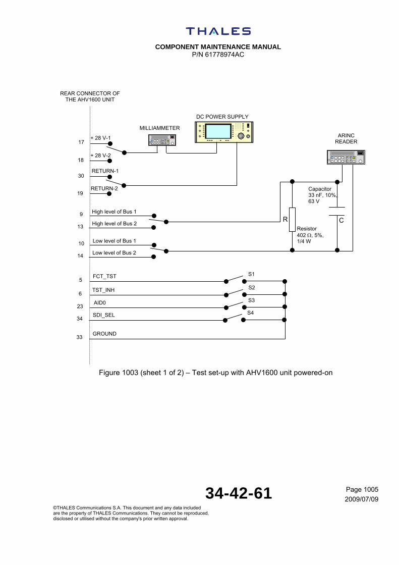
COMPONENT MAINTENANCE MANUAL
P/N 61778974AC
34-42-61 Page 1005
2009/07/09©THALES Communications S.A. This document and any data included are the property of THALES Communications. They cannot be reproduced, disclosed or utilised without the company's prior written approval.
Figure 1003 (sheet 1 of 2) – Test set-up with AHV1600 unit powered-on
DC POWER SUPPLY
+ 28 V-1 ARINC READER
+ 28 V-2
17
30
19
18
S1 5
S2 6
S3 23
S4 34
33
MILLIAMMETER
9
13
High level of Bus 1
High level of Bus 2 Resistor 402 , 5%, 1/4 W
Capacitor 33 nF, 10%, 63 V
R C
10
14
Low level of Bus 1
Low level of Bus 2
RETURN-1
RETURN-2
FCT_TST
TST_INH
AID0
SDI_SEL
GROUND
REAR CONNECTOR OF THE AHV1600 UNIT
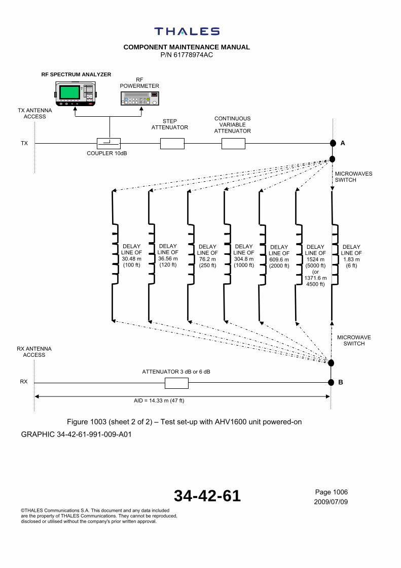
COMPONENT MAINTENANCE MANUAL
P/N 61778974AC
34-42-61 Page 1006
2009/07/09©THALES Communications S.A. This document and any data included are the property of THALES Communications. They cannot be reproduced, disclosed or utilised without the company's prior written approval.
Figure 1003 (sheet 2 of 2) – Test set-up with AHV1600 unit powered-on
GRAPHIC 34-42-61-991-009-A01
CONTINUOUS VARIABLE
ATTENUATOR
STEP ATTENUATOR
DELAY LINE OF 30.48 m (100 ft)
A
B
ATTENUATOR 3 dB or 6 dB
COUPLER 10dB
RF SPECTRUM ANALYZER
AID = 14.33 m (47 ft)
RF POWERMETER
TX ANTENNA ACCESS
IrML
DELAY LINE OF 36.56 m (120 ft)
DELAY LINE OF 76.2 m (250 ft)
DELAY LINE OF 304.8 m (1000 ft)
DELAY LINE OF 609.6 m (2000 ft)
DELAY LINE OF 1524 m (5000 ft)
(or 1371.6 m 4500 ft)
DELAY LINE OF 1.83 m (6 ft)
TX
RX ANTENNA ACCESS
RX
MICROWAVES SWITCH
MICROWAVE SWITCH

COMPONENT MAINTENANCE MANUAL
P/N 61778974AC
34-42-61 Page 1007
2009/07/09©THALES Communications S.A. This document and any data included are the property of THALES Communications. They cannot be reproduced, disclosed or utilised without the company's prior written approval.
NOTE: (in accordance with Figure 1003) The electrical length existing between Tx and Rx connectors of the AHV1600 unit when points A and B are directly connected including the electrical length of the interface cables, adapters, variable attenuator, and couplers should correspond to the AID simulated height (14.33 m (47 ft)).
NOTE: (in accordance with Figure 1003) All the delay lines used for the different measurements must be calibrated to know with accuracy their electrical length and their attenuation.
NOTE: (in accordance with Figure 1003) The delay line of 1524 m (5000 ft) can be replaced by a delay line of 1371.6 m (4500 ft) (in the functional test procedure, are given the tolerances between brackets for this delay line).
NOTE: (in accordance with Figure 1003) RF attenuation of each element (cables, delay line) must be known prior an acceptance tests in order to take into account consideration for sensitivity and RF transmitted power measurements.
NOTE: (in accordance with Figure 1003) For the test “Response time performance during a height step”, it is necessary to use a microwave switch to reduce at maximum the commutation time between the delay line of 30.48 m (100 ft) and the delay line of 365.76 m (1200 ft).
NOTE: (in accordance with Figure 1003) The different values of delay lines used in the Functional Test procedure must respect the applicable tolerance of 2% with the desired delay lines (refer to the table below).
TABLE 34-42-61-992-101-A01
HEIGHT
Height (m (ft)) Height tol. (%) Height tol. (m (ft)) Hsim min. (m (ft)) Hsim max. (m (ft))
1.83 (6) 2% 0.04 (0.12) 1.18 (3.88) 2.48 (8.12)
30.48 (100) 2% 0.61 (2) 29.26 (96) 31.70 (104)
76.2 (250) 2% 1.52 (5) 74.07 (243) 78.33 (257)
304.8 (1000) 2% 6.1 (20) 298.09 (978) 311.50 (1022)
609.6 (2000) 2% 12.19 (40) 596.80 (1958) 622.40 (2042)
1371.6 (4500) 2% 27.43 (90) 1343.56 (4408) 1399.64 (4592)
1524 (5000) 2% 30.48 (100) 1461.82 (4796) 1555.19 (5102)

COMPONENT MAINTENANCE MANUAL
P/N 61778974AC
34-42-61 Page 1008
2009/07/09©THALES Communications S.A. This document and any data included are the property of THALES Communications. They cannot be reproduced, disclosed or utilised without the company's prior written approval.
TABLE 34-42-61-992-102-A01
Control State Configuration (refer to Figure 1003)
FCT_TST OPEN Contact 5 is not linked to contact 33 (S1 is open)
FCT_TST GND Contact 5 is linked to contact 33 (S1 is closed)
TST_INH OPEN Contact 6 is not linked to contact 33 (S2 is open)
TST_INH GND Contact 6 is linked to contact 33 (S2 is closed)
AID0 0 Contact 23 is linked to contact 33 (S3 is closed)
SDI_SEL GND Contact 34 is linked to contact 33 (S4 is closed)
SDI_SEL OPEN Contact 34 is not linked to contact 33 (S4 is open)
Figure 1004: Table of configuration of the controls of the AHV1600 unit
GRAPHIC 34-42-61-991-010-A01
NOTE: Contactors S1 to S4 are mentioned in accordance with the Test set up shown in Figure 1003 (other mean may be used to change the configuration of the controls).

COMPONENT MAINTENANCE MANUAL
P/N 61778974AC
34-42-61 Page 1009
2009/07/09©THALES Communications S.A. This document and any data included are the property of THALES Communications. They cannot be reproduced, disclosed or utilised without the company's prior written approval.
Figure 1005 – In-rush current measurement
GRAPHIC 34-42-61-991-011-A01
NOTE: This test set-up must be inserted in the test set-up shown on the Figure 1003
NOTE: To do the different connections to the rear connector of the AHV1600 unit, use a connector as defined in Special Tools, Fixtures and Equipment section.
NOTE: The same measurement must be done between pins 18 and 19 (the current probe must be put on the wire connected on the pin 18 of the test set-up shown on Figure 1003)
Positive output Negative output
DC POWER SUPPLY
Current probe
Current probe
amplifier
Power module
Oscilloscope
Channel A
17
30
Rear connector of the AHV1600 unit

COMPONENT MAINTENANCE MANUAL
P/N 61778974AC
34-42-61 Page 1010
2009/07/09©THALES Communications S.A. This document and any data included are the property of THALES Communications. They cannot be reproduced, disclosed or utilised without the company's prior written approval.
Figure 1006 – Measurement of the electrical characteristics of the Arinc 429 output signals
GRAPHIC 34-42-61-991-012-A01
OSCILLOSCOPE
9
13
High level of Bus 1
High level of Bus 2 Resistor 402 , 5%, 1/4 W
Capacitor 30 nF, 10%, 63 V
C
10
14
Low level of Bus 1
Low level of Bus 2
CHANNEL A CHANNEL B
R
33
GROUND

COMPONENT MAINTENANCE MANUAL
P/N 61778974AC
34-42-61 Page 1011
2009/07/09©THALES Communications S.A. This document and any data included are the property of THALES Communications. They cannot be reproduced, disclosed or utilised without the company's prior written approval.
Figure 1007 – Levels L1, L2 and L3 to measure on the Arinc 429 output signals
GRAPHIC 34-42-61-991-013-A01
NOTE: Rise time T1 and fall time T2 are measured between the 10% and the 90% voltage amplitude of the pulse.
NOTE: T3 is the time between the 50% voltage amplitude of the rising edge and the 50% voltage amplitude of the rising edge of the next pulse.
NOTE: T4 is the time between the 50% voltage amplitude of the rising edge and the 50% voltage amplitude of the falling edge.
L2
T1
Reference level (0V) of the oscilloscope
L1
L3
T3
T4
T2

COMPONENT MAINTENANCE MANUAL
P/N 61778974AC
34-42-61 Page 1012
2009/07/09©THALES Communications S.A. This document and any data included are the property of THALES Communications. They cannot be reproduced, disclosed or utilised without the company's prior written approval.
SUBTASK 34-42-61-871-003-A01
C. Sequence of the equipment identifier data word labels “371”
By decoding the equipment identifier data word labels “371”, it is possible to decode the position (following the SDI value), the part number and the serial number of the AHV1600 unit.
A complete sequence contains 9 equipment identifier data word labels “371” as described below.
The sequence is sent continuously and begins by the STX world and ends by the EOT world.
NOTE: To decode a sequence, it is necessary to use the ISO5 alphabet (refer to Figure 1005).
NOTE: To ease the decoding of a complete sequence, it is necessary to use an Arinc tool (software) which allows the recording of 17 (at least) equipment identifier data word labels “371”.
Example of a complete sequence:
Equipment identifier data:
- “Name”: RA1
- “Part Number”: 61778974AC
- “Serial Number”: 01025
TABLE 34-42-61-992-103-A01
Transmission of first word label “371” 32 31 30 29 28 27 26 25 24 23 22 21 20 19 18 17 16 15 14 13 12 11 10 9 8 7 6 5 4 3 2 1
Par
ity
STX Spare
MS
B
Block Word Count
LSB
LSB
Label « 371 »
MS
B
0 0 0 0 0 0 1 0 0 0 0 0 0 0 0 0 0 0 0 0 1 0 0 1 1 0 0 1 1 1 1 1
TABLE 34-42-61-992-104-A01
Transmission of intermediate words label “371 32 31 30 29 28 27 26 25 24 23 22 21 20 19 18 17 16 15 14 13 12 11 10 9 8 7 6 5 4 3 2 1
Par
ity
MS
B
1
LSB
Spa
re
MS
B
A
LSB
Spa
re
MS
B
R
LSB
LSB
Label « 371 »
MS
B
1 0 1 1 0 0 0 1 0 1 0 0 0 0 0 1 0 1 0 1 0 0 1 0 1 0 0 1 1 1 1 1

COMPONENT MAINTENANCE MANUAL
P/N 61778974AC
34-42-61 Page 1013
2009/07/09©THALES Communications S.A. This document and any data included are the property of THALES Communications. They cannot be reproduced, disclosed or utilised without the company's prior written approval.
TABLE 34-42-61-992-105-A01
Transmission of intermediate words label “371 (continued)
32 31 30 29 28 27 26 25 24 23 22 21 20 19 18 17 16 15 14 13 12 11 10 9 8 7 6 5 4 3 2 1
Par
ity
MS
B
1 LS
B
Spa
re
MS
B
6
LSB
Spa
re
MS
B
Carriage Return
LSB
LSB
Label « 371 »
MS
B
1 0 1 1 0 0 0 1 0 0 1 1 0 1 1 0 0 0 0 0 1 1 0 1 1 0 0 1 1 1 1 1
TABLE 34-42-61-992-106-A01
Transmission of intermediate words label “371 (continued)
32 31 30 29 28 27 26 25 24 23 22 21 20 19 18 17 16 15 14 13 12 11 10 9 8 7 6 5 4 3 2 1
Par
ity
MS
B
8
LSB
Spa
re
MS
B
7 LS
B
Spa
re
MS
B
7
LSB
LSB
Label « 371 »
MS
B
0 0 1 1 1 0 0 0 0 0 1 1 0 1 1 1 0 0 1 1 0 1 1 1 1 0 0 1 1 1 1 1
TABLE 34-42-61-992-107-A01
Transmission of intermediate words label “371 (continued)
32 31 30 29 28 27 26 25 24 23 22 21 20 19 18 17 16 15 14 13 12 11 10 9 8 7 6 5 4 3 2 1
Par
ity
MS
B
4
LSB
Spa
re
MS
B
7
LSB
Spa
re
MS
B
9
LSB
LSB
Label « 371 »
MS
B
1 0 1 1 0 1 0 0 0 0 1 1 0 1 1 1 0 0 1 1 1 0 0 1 1 0 0 1 1 1 1 1
TABLE 34-42-61-992-108-A01
Transmission of intermediate words label “371 (continued)
32 31 30 29 28 27 26 25 24 23 22 21 20 19 18 17 16 15 14 13 12 11 10 9 8 7 6 5 4 3 2 1
Par
ity
MS
B
Carriage Return
LSB
Spa
re
MS
B
A
LSB
Spa
re
MS
B
A
LSB
LSB
Label « 371 »
MS
B
0 0 0 0 1 1 0 1 0 1 0 0 0 0 0 1 0 1 0 0 0 0 0 1 1 0 0 1 1 1 1 1
TABLE 34-42-61-992-109-A01
Transmission of intermediate words label “371 (continued)
32 31 30 29 28 27 26 25 24 23 22 21 20 19 18 17 16 15 14 13 12 11 10 9 8 7 6 5 4 3 2 1
Par
ity
MS
B
0
LSB
Spa
re
MS
B
1
LSB
Spa
re
MS
B
0
LSB
LSB
Label « 371 »
MS
B
0 0 1 1 0 0 0 0 0 0 1 1 0 0 0 1 0 0 1 1 0 0 0 0 1 0 0 1 1 1 1 1
TABLE 34-42-61-992-110-A01

COMPONENT MAINTENANCE MANUAL
P/N 61778974AC
34-42-61 Page 1014
2009/07/09©THALES Communications S.A. This document and any data included are the property of THALES Communications. They cannot be reproduced, disclosed or utilised without the company's prior written approval.
Transmission of intermediate words label “371 (end) 32 31 30 29 28 27 26 25 24 23 22 21 20 19 18 17 16 15 14 13 12 11 10 9 8 7 6 5 4 3 2 1
Par
ity
MS
B
SP LS
B
Spa
re
MS
B
5
LSB
Spa
re
MS
B
2
LSB
LSB
Label « 371 »
MS
B
1 0 1 0 0 0 0 0 0 0 1 1 0 1 0 1 0 0 1 1 0 0 1 0 1 0 0 1 1 1 1 1
TABLE 34-42-61-992-111-A01
Transmission of last word label “371” 32 31 30 29 28 27 26 25 24 23 22 21 20 19 18 17 16 15 14 13 12 11 10 9 8 7 6 5 4 3 2 1
Par
ity
EOT Spare
LSB
Label « 371 »
MS
B
0 0 0 0 0 1 0 0 0 0 0 0 0 0 0 0 0 0 0 0 0 0 0 0 1 0 0 1 1 1 1 1

COMPONENT MAINTENANCE MANUAL
P/N 61778974AC
34-42-61 Page 1015
2009/07/09©THALES Communications S.A. This document and any data included are the property of THALES Communications. They cannot be reproduced, disclosed or utilised without the company's prior written approval.
TABLE 34-42-61-992-112-A01
ISO5 alphabet
7 6 5
0 0 0
0 0 1
0 1 0
0 1 1
1 0 0
1 0 1
1 1 0
1 1 1
Bits
4 3 2 1 Column Row
0 1 2 3 4 5 6 7
0 0 0 0 0 NUL SP 0 P MCDU MENU SEL1
0 0 0 1 1 CNTRL DC1 ! 1 A Q SPECIAL FUNCTION SEL2
0 0 1 0 2 STX DC2 " 2 B R KEY 1 TO 13 SEL3
0 0 1 1 3 ETX DC3 # 3 C S SEL4
0 1 0 0 4 EOT DC4 4 D T SEL5
0 1 0 1 5 ENQ NAK % 5 E U SEL6
0 1 1 0 6 ACK SYN & 6 F V PREV PAGE
0 1 1 1 7 ' 7 G W NEXT PAGE
1 0 0 0 8 CLR LOGOFF ( 8 H X SER1
1 0 0 1 9 ) 9 I Y SER2
1 0 1 0 10 * : J Z SER3
1 0 1 1 11 + ; K [ SER4
1 1 0 0 12 0 , < L \ SER5
1 1 0 1 13 CARRIAGE RETURN - = M ] SER6
1 1 1 0 14 . > N
1 1 1 1 15 / ? O OR CLR/DEL
The highlighted characters correspond to the characters used by the equipment identifier data word label “371”.
Figure 1008 – Table of ISO5 alphabet
GRAPHIC 34-42-61-991-014-A01

COMPONENT MAINTENANCE MANUAL
P/N 61778974AC
34-42-61 Page 1016
2009/07/09©THALES Communications S.A. This document and any data included are the property of THALES Communications. They cannot be reproduced, disclosed or utilised without the company's prior written approval.
TABLE 34-42-61-992-113-A01 Tests of the AHV1600
TEST PROCEDURE DESCRIPTION
(1) Refer to SUBTASK 34-42-61-700-001-01
Lightning protection of the power supply inputs and Arinc outputs
(2) Refer to SUBTASK 34-42-61-700-002-01
Lightning protection of the Radio Frequency inputs “RX”, “TX” and discretes inputs
(4) Refer to SUBTASK 34-42-61-700-004-01
Power consumption
(5) Refer to SUBTASK 34-42-61-700-005-01
RF bandwidth
(6) Refer to SUBTASK 34-42-61-700-006-01
RF transmitted power
(7) Refer to SUBTASK 34-42-61-700-007-01
Electrical characteristics of the Arinc 429 output signals
(8) Refer to SUBTASK 34-42-61-700-008-01
Refresh rate of Arinc labels on Arinc bus N°1 and Arinc bus N°2
(9) Refer to SUBTASK 34-42-61-700-009-01
Checking of data word labels “271”, “272”, “371” and “377”
(10) Refer to SUBTASK 34-42-61-700-010-01
SDI selection discrete
(11) Refer to SUBTASK 34-42-61-700-011-01
Test Inhibit discrete
(12) Refer to SUBTASK 34-42-61-700-012-01
Functional Test discrete
(13) Refer to SUBTASK 34-42-61-700-013-01
Search mode and track mode
(14) Refer to SUBTASK 34-42-61-700-014-01
Antenna failure
(15) Refer to SUBTASK 34-42-61-700-015-01
Built In Test function
(16) Refer to SUBTASK 34-42-61-700-016-01
Sensitivity
(17) Refer to SUBTASK 34-42-61-700-017-01
Height accuracy
(18) Refer to SUBTASK 34-42-61-700-018-01
Response time performance during a height step
(19) Refer to SUBTASK 34-42-61-700-019-01
Operation at + 22 V and + 18 V
(20) Refer to SUBTASK 34-42-61-700-020-01
Operation at + 30.3 V
Figure 1009 – List of the tests of the functional test procedure GRAPHIC 34-42-61-991-015-A01
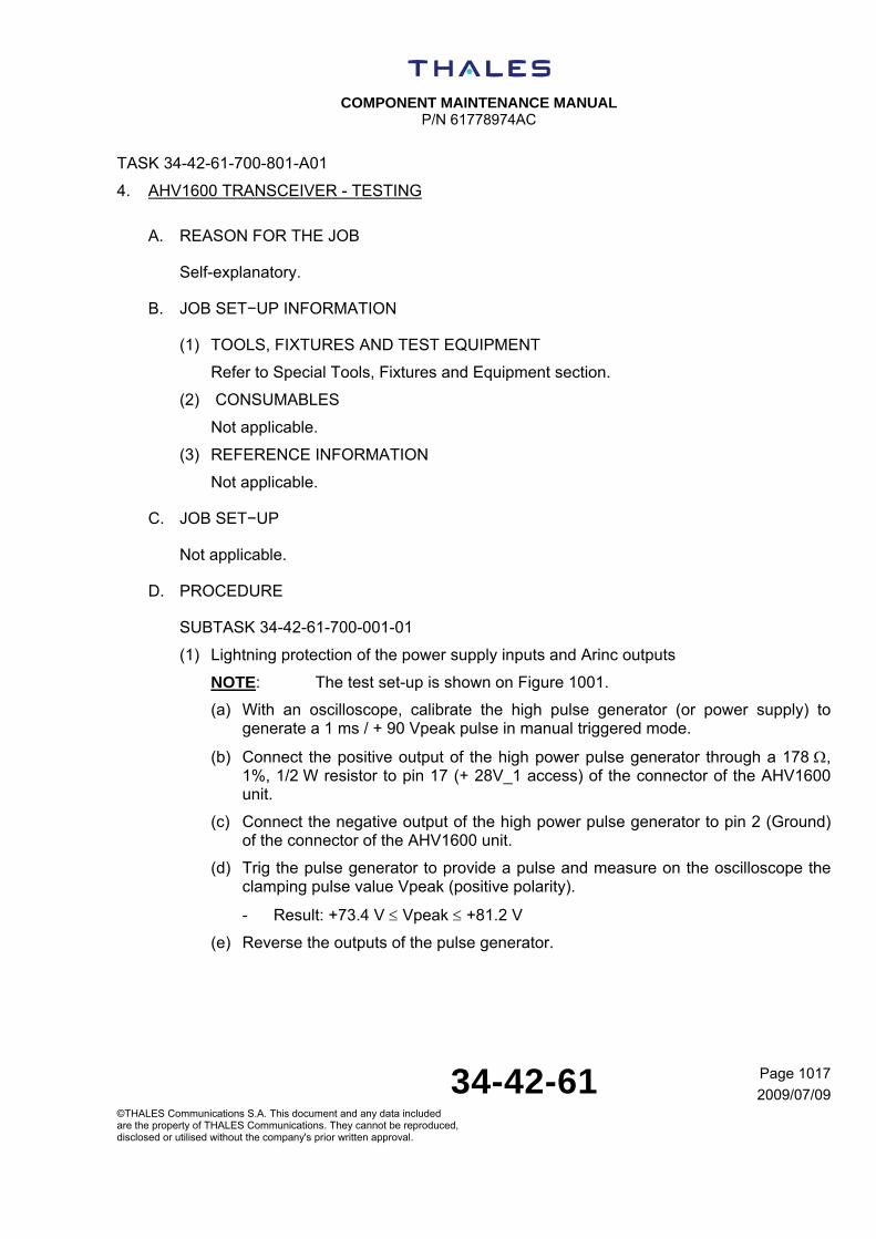
COMPONENT MAINTENANCE MANUAL
P/N 61778974AC
34-42-61 Page 1017
2009/07/09©THALES Communications S.A. This document and any data included are the property of THALES Communications. They cannot be reproduced, disclosed or utilised without the company's prior written approval.
TASK 34-42-61-700-801-A01
4. AHV1600 TRANSCEIVER - TESTING
A. REASON FOR THE JOB
Self-explanatory.
B. JOB SET−UP INFORMATION
(1) TOOLS, FIXTURES AND TEST EQUIPMENT
Refer to Special Tools, Fixtures and Equipment section.
(2) CONSUMABLES
Not applicable.
(3) REFERENCE INFORMATION
Not applicable.
C. JOB SET−UP
Not applicable.
D. PROCEDURE
SUBTASK 34-42-61-700-001-01
(1) Lightning protection of the power supply inputs and Arinc outputs
NOTE: The test set-up is shown on Figure 1001.
(a) With an oscilloscope, calibrate the high pulse generator (or power supply) to generate a 1 ms / + 90 Vpeak pulse in manual triggered mode.
(b) Connect the positive output of the high power pulse generator through a 178 , 1%, 1/2 W resistor to pin 17 (+ 28V_1 access) of the connector of the AHV1600 unit.
(c) Connect the negative output of the high power pulse generator to pin 2 (Ground) of the connector of the AHV1600 unit.
(d) Trig the pulse generator to provide a pulse and measure on the oscilloscope the clamping pulse value Vpeak (positive polarity).
- Result: +73.4 V Vpeak +81.2 V
(e) Reverse the outputs of the pulse generator.

COMPONENT MAINTENANCE MANUAL
P/N 61778974AC
34-42-61 Page 1018
2009/07/09©THALES Communications S.A. This document and any data included are the property of THALES Communications. They cannot be reproduced, disclosed or utilised without the company's prior written approval.
(f) Trig the pulse generator to provide a pulse and measure on the oscilloscope the clamping pulse value Vpeak (negative polarity).
- Result: -81.2 V Vpeak -73.4 V
(g) Connect the positive output of the high power pulse generator through a 178 , 1%, 1/2 W resistor to pin 30 (- 28V_1 access) of the connector of the AHV1600 unit.
(h) Connect the negative output of the high power pulse generator to pin 2 (Ground) of the connector of the AHV1600 unit.
(i) Repeat steps (d) to (f).
(j) Connect the positive output of the high power pulse generator through a 178 , 1%, 1/2 W resistor to pin 18 (+ 28V_2 access) of the connector of the AHV1600 unit.
(k) Connect the negative output of the high power pulse generator to pin 2 (Ground) of the connector of the AHV1600 unit.
(l) Repeat steps (d) to (f).
(m) Connect the positive output of the high power pulse generator through a 178 , 1%, 1/2 W resistor to pin 19 (- 28V_2 access) of the connector of the AHV1600 unit.
(n) Connect the negative output of the high power pulse generator to pin 2 (Ground) of the connector of the AHV1600 unit.
(o) Repeat steps (d) to (f).
(p) With an oscilloscope, calibrate the high pulse generator to generate a 1 ms / + 55 Vpeak pulse in manual triggered mode.
(q) Connect the positive output of the high power pulse generator through a 178 , 1%, 1/2 W resistor to pin 9 (TX 429 High_1) of the connector of the AHV1600 unit.
(r) Connect the negative output of the high power pulse generator to pin 2 (Ground) of the connector of the AHV1600 unit.
(s) Trig the pulse generator to provide a pulse and measure on the oscilloscope the clamping pulse value Vpeak (positive polarity).
- Result: +10.4 V Vpeak +11.9 V
(t) Reverse the outputs of the pulse generator.
(u) Trig the pulse generator to provide a pulse and measure on the oscilloscope the clamping pulse value Vpeak (negative polarity).
- Result: -11.9 V Vpeak -10.4 V
(v) Connect the positive output of the high power pulse generator through a 178 , 1%, 1/2 W resistor to pin 10 (TX 429 Low_1) of the connector of the AHV1600 unit.

COMPONENT MAINTENANCE MANUAL
P/N 61778974AC
34-42-61 Page 1019
2009/07/09©THALES Communications S.A. This document and any data included are the property of THALES Communications. They cannot be reproduced, disclosed or utilised without the company's prior written approval.
(w) Connect the negative output of the high power pulse generator to pin 2 (Ground) of the connector of the AHV1600 unit.
(x) Repeat steps (s) to (u).
(y) Connect the positive output of the high power pulse generator through a 178 , 1%, 1/2 W resistor to pin 13 (TX 429 High_2) of the connector of the AHV1600 unit.
(z) Connect the negative output of the high power pulse generator to pin 2 (Ground) of the connector of the AHV1600 unit.
(aa) Repeat steps (s) to (u).
(bb) Connect the positive output of the high power pulse generator through a 178 , 1%, 1/2 W resistor to pin 14 (TX 429 Low_2) of the connector of the AHV1600 unit.
(cc) Connect the negative output of the high power pulse generator to pin 2 (Ground) of the connector of the AHV1600 unit.
(dd) Repeat steps (s) to (u).
(ee) Disconnect the high power pulse generator from the AHV1600 unit.
SUBTASK 34-42-61-700-002-01
(2) Lightning protection of the Radio Frequency inputs “RX”, “TX” and discretes inputs
NOTE: The test set-up is shown on Figure 1002.
(a) On the DC power supply, adjust the power supply current limit to: 10 mA 0.10 mA (if necessary, with a DC ammeter connected to the output of the DC power supply).
(b) Connect the positive output of the DC power supply to the central contact of the “RX” antenna access of the AHV1600 unit.
(c) Connect the negative output of the DC power supply to pin 2 (Ground) of the connector of the AHV1600 unit.
(d) Increase the DC power supply voltage until the clipping voltage Vlim is reached (positive polarity).
- Result: + 15.2 V Vlimit + 18.6 V
(e) Set to 0V the output voltage and reverse the outputs of the DC power supply.
(f) Increase the DC power supply voltage until the clipping voltage Vlim is reached (negative polarity).
- Result: - 14.3V Vlimit -10.3 V
(g) Connect the positive output of the DC power supply to the central contact of the “TX” antenna access of the AHV1600 unit.
(h) Connect the negative output of the DC power supply to pin 2 (Ground) of the connector of the AHV1600 unit.

COMPONENT MAINTENANCE MANUAL
P/N 61778974AC
34-42-61 Page 1020
2009/07/09©THALES Communications S.A. This document and any data included are the property of THALES Communications. They cannot be reproduced, disclosed or utilised without the company's prior written approval.
(i) Repeat steps (d) to (f).
(j) Disconnect the DC power supply from the AHV1600 unit.
(k) On the DC power supply, adjust the power supply current limit to: 2 mA 0.10 mA (if necessary, with a DC ammeter connected to the output of the DC power supply).
(l) Connect the positive output of the DC power supply to pin 5 (Funct_Test) of the connector of the AHV1600 unit.
(m) Connect the negative output of the DC power supply to pin 2 (Ground) of the connector of the AHV1600 unit.
(n) Increase the DC power supply voltage until the clipping voltage Vlim is reached (positive polarity).
- Result: + 36.8 V Vlimit + 42.8 V
(o) Set to 0V the output voltage and reverse the outputs of the DC power supply.
(p) Increase the DC power supply voltage until the clipping voltage Vlim is reached (negative polarity).
- Result: - 5.3 V Vlimit - 1.3 V
(q) Connect the positive output of the DC power supply to pin 6 (Test_Inhib) of the rear connector of the AHV1600 unit.
(r) Connect the negative output of the DC power supply to pin 2 (Ground) of the rear connector of the AHV1600 unit.
(s) Repeat steps (n) to (p).
(t) Connect the positive output of the DC power supply to pin 23 (AID_0) of the rear connector of the AHV1600 unit.
(u) Connect the negative output of the DC power supply to pin 2 (Ground) of the rear connector of the AHV1600 unit.
(v) Repeat steps (n) to (p).
(w) Connect the positive output of the DC power supply to pin 24 (AID_1) of the rear connector of the AHV1600 unit.
(x) Connect the negative output of the DC power supply to pin 2 (Ground) of the rear connector of the AHV1600 unit.
(y) Repeat steps (n) to (p).
(z) Connect the positive output of the DC power supply to pin 16 (AID_2) of the rear connector of the AHV1600 unit.
(aa) Connect the negative output of the DC power supply to pin 2 (Ground) of the rear connector of the AHV1600 unit.
(bb) Repeat steps (n) to (p).

COMPONENT MAINTENANCE MANUAL
P/N 61778974AC
34-42-61 Page 1021
2009/07/09©THALES Communications S.A. This document and any data included are the property of THALES Communications. They cannot be reproduced, disclosed or utilised without the company's prior written approval.
(cc) Connect the positive output of the DC power supply to pin 20 (AID_P) of the rear connector of the AHV1600 unit.
(dd) Connect the negative output of the DC power supply to pin 2 (Ground) of the rear connector of the AHV1600 unit.
(ee) Repeat steps (n) to (p).
(ff) Connect the positive output of the DC power supply to pin 34 (SDI_Sel) of the rear connector of the AHV1600 unit.
(gg) Connect the negative output of the DC power supply to pin 2 (Ground) of the rear connector of the AHV1600 unit.
(hh) Repeat steps (n) to (p).
(ii) Disconnect the DC power supply from the AHV1600 unit.
SUBTASK 34-42-61-700-003-01
(3) Configuration of the AHV1600
NOTE: The test set-up is shown on Figure 1003.
(a) Insert a delay line of 1.83 m (6 ft) between points A and B.
(b) Adjust the total loop attenuation to 76 dB 1 dB between “Tx” and “Rx” connectors of the AHV1600 unit.
(c) Configure the AHV1600 unit as follows (refer to Figures 1003 and 1004).
- FCT_TST = OPEN
- TST_INH = OPEN
- AID0 = 0
- SDI_SEL = GND
SUBTASK 34-42-61-700-004-01
(4) Power consumption
NOTE: The test set-up is shown on Figure 1003.
(a) Connect the DC power supply to pins 17 (+ 28V_1 access) and 30 (- 28V_1 access) of the rear connector of the AHV1600 unit with a miliammeter.
(b) Adjust the output voltage of the DC Power Supply to + 28 VDC 0.5 VDC.
(c) Power-on the AHV1600.
(d) Wait 10 seconds.
(e) Measure the value Ic of the DC current on the milliammeter.
- Result: Ic 0.727 A
(f) Power-off the AHV1600 unit (the DC Power Supply is stopped).

COMPONENT MAINTENANCE MANUAL
P/N 61778974AC
34-42-61 Page 1022
2009/07/09©THALES Communications S.A. This document and any data included are the property of THALES Communications. They cannot be reproduced, disclosed or utilised without the company's prior written approval.
(g) Disconnect the ammeter (the positive output of the DC power supply is directly connected to the pin 17 (+ 28V_1 access) of the rear connector of the AHV1600 unit).
(h) Connect the current probe to the wire linked to the pin 17 (+ 28V_1 access) and do the test set-up shown on Figure 1005.
(i) Calibrate the digital oscilloscope in triggered single shot on the rising slope of the current probe.
(j) Power-on the AHV1600.
(k) On the digital oscilloscope, check the peak pulse current value I at power-up.
- Result: I < 22APeak
(l) On the digital oscilloscope, check the time duration Td for the in-rush current reaches 63% of the peak pulse value.
- Result: Td 750s
(m) Power-off the AHV1600 unit.
(n) Connect the DC power supply to pins 18 (+ 28V_2 access) and 19 (- 28V_2 access) of the rear connector of the AHV1600 unit with a miliammeter.
(o) Adjust the output voltage of the DC Power Supply to + 28 VDC 0.5 VDC.
(p) Power-on the AHV1600.
(q) Repeat steps (d) and (e).
- Result: Ic 0.727 A
(r) Power-off the AHV1600 unit.
(s) Disconnect the ammeter (the positive output of the DC power supply is directly connected to the pin 18 of the rear connector of the AHV1600 unit).
(t) Connect the current probe to the wire linked to the pin 18 (+ 28V_2 access) and do the test set-up shown on Figure 1005.
(u) Calibrate the digital oscilloscope in triggered single shot on the rising slope of the current probe.
(v) Power-on the AHV1600.
(w) On the digital oscilloscope, check the peak pulse current value I at power-up.
- Result: I < 22 A Peak
(x) On the digital oscilloscope, check the time duration Td for the in-rush current reaches 63% of the peak pulse value.
- Result: Td 750 s
(y) Power-off the AHV1600 unit.
SUBTASK 34-42-61-700-005-01
COMPONENT MAINTENANCE MANUAL
P/N 61778974AC
34-42-61 Page 1023
2009/07/09©THALES Communications S.A. This document and any data included are the property of THALES Communications. They cannot be reproduced, disclosed or utilised without the company's prior written approval.
(5) RF bandwidth
NOTE: The test set-up is shown on Figure 1003.
(a) Adjust the total loop attenuation (with the variable attenuators) to obtain the maximum attenuation between “Tx” and “Rx” connectors of the AHV1600 unit.
(b) Power-on the AHV1600 unit with the DC Power Supply connected to pins 17 (+ 28V_1 access) and 30 (- 28V_1 access) of the rear connector of the AHV1600 unit.
(c) Wait 10 seconds.
(d) On the RF spectrum analyzer, measure the low transmitted Radio Frequency Fmin.
- Result: Fmin 4.2 GHz
(e) On the RF spectrum analyzer, measure the high transmitted Radio Frequency Fmax.
- Result: Fmax 4.4 GHz
(f) Power-off the AHV1600 unit.
SUBTASK 34-42-61-700-006-01
(6) RF transmitted power
NOTE: The test set-up is shown on Figure 1003.
The Arinc reader is connected to points 9 (TX 429 High_1) and 10 (TX 429 Low_1) of the connector of the AHV1600 unit.
(a) Configure the AHV1600 unit as follows (refer to Figures 1003 and 1004):
- FCT_TST = OPEN
- TST_INH = OPEN
- AID0 = 0
- SDI_SEL = GND
(b) Power-on the AHV1600 unit with the DC Power Supply connected to pins 17 (+ 28V_1 access) and 30 (- 28V_1 access) of the rear connector of the AHV1600 unit.
(c) Wait 10 seconds.
(d) On the RF Power meter, read the value P1 and calculate P according to the attenuation A (between “TX” connector of the ERT560 and the probe of the RF Power meter).
P(dBm) = P1(dBm) + A(dB).
- Result: P = 4 dBm 2 dB

COMPONENT MAINTENANCE MANUAL
P/N 61778974AC
34-42-61 Page 1024
2009/07/09©THALES Communications S.A. This document and any data included are the property of THALES Communications. They cannot be reproduced, disclosed or utilised without the company's prior written approval.
(e) Between points A and B of the test set-up is shown on Figure 1003, insert a delay line of 30.48 m (100 ft).
(f) Adjust the total loop attenuation (with the variable attenuators) to obtain 100 dB 1 dB of attenuation between Tx and Rx connectors of the AHV1600 unit.
(g) On the RF Power meter, read the value P1 and calculate P according to the attenuation A (between TX connector of the ERT560 and the probe of the RF Power meter).
P(dBm) = P1(dBm) + A(dB).
- Result: P = 5 dBm 2 dB
(h) Repeat steps (e) to (g) with a delay line of 76.2 m (250 ft) and a total loop attenuation of 108 dB 1 dB.
- Result: P = 9 dBm 2 dB
(i) Repeat steps (e) to (g) with a delay line of 304.8 m (1000 ft) and a total loop attenuation of 118 dB 1 dB.
- Result: P = 15 dBm 2 dB
(j) Repeat steps (e) to (g) with a delay line of 609.6 m (2000 ft) and a total loop attenuation of 124 dB 1 dB.
- Result: P = 17 dBm 2 dB
(k) Repeat steps (e) to (g) with a delay line of 1524 m (5000 ft) (or 1372 m (4500 ft)) and a total loop attenuation of 132 dB 1 dB.
- Result: P = 17 dBm 2 dB
(l) Power-off the AHV1600 unit.
SUBTASK 34-42-61-700-007-01
(7) Electrical characteristics of the output signals Arinc 429
NOTE: The test set-up is shown on Figures 1003 and 1006.
The Arinc reader is replaced by a digital oscilloscope.
The resistor R and the capacitor C are used to simulate 20 Arinc loads.
(a) Configure the AHV1600 unit as follows (refer to Figures 1003 and 1004)
- FCT_TST = OPEN
- TST_INH = OPEN
- AID0 = 0
- SDI_SEL = GND
(b) Connect the oscilloscope to pins 9 (TX 429 High_1) and 10 (TX 429 Low_1) of the rear connector of the AHV1600 unit.
(c) On the oscilloscope, select the function “channel A + channel B”.
COMPONENT MAINTENANCE MANUAL
P/N 61778974AC
34-42-61 Page 1025
2009/07/09©THALES Communications S.A. This document and any data included are the property of THALES Communications. They cannot be reproduced, disclosed or utilised without the company's prior written approval.
(d) Power-on the AHV1600 unit with the DC Power Supply connected to pins 17 (+ 28V_1 access) and 30 (- 28V_1 access) of the rear connector of the AHV1600 unit.
(e) Wait 10 seconds.
(f) On the oscilloscope, measure the level L1 (refer to Figure 1007).
- Result: - 11 VDC L1 - 7.25 VDC
(g) On the oscilloscope, measure the level L2 (refer to Figure 1007).
- Result: + 7.25 VDC L2 + 11 VDC
(h) On the oscilloscope, measure the level L3 (refer to Figure 1007).
- Result: - 0.5 VDC L3 + 0.5 VDC
(i) Connect the oscilloscope to pins 13 (TX 429 High_2) and 14 (TX 429 Low_2) of the rear connector of the AHV1600 unit
(j) On the oscilloscope, measure the level L1 (refer to Figure 1007).
- Result: - 11 VDC L1 - 7.25 VDC
(k) On the oscilloscope, measure the level L2 (refer to Figure 1007).
- Result: + 7.25 VDC L2 + 11 VDC
(l) On the oscilloscope, measure the level L3 (refer to Figure 1007).
- Result: - 0.5 VDC L3 + 0.5 VDC
(m) Power-off the AHV1600 unit.
(n) Remove the resistor R and the capacitor C (refer to Figure 1006).
(o) Connect the oscilloscope to pins 9 (TX 429 High_1) and 10 (TX 429 Low_1) of the rear connector of the AHV1600 unit.
(p) Power-on the AhV1600 unit.
(q) Wait 10 seconds.
(r) On the oscilloscope, measure the time T1 (refer to Figure 1007).
- Result: T1 = 10 s 5 s
(s) On the oscilloscope, measure the time T2 (refer to Figure 1007).
- Result: T2 = 10 s 5 s
(t) On the oscilloscope, measure the time T3 (refer to Figure 1007).
- Result: T3 = 80 s 2 s
(u) On the oscilloscope, measure the time T4 (refer to Figure 1007).
- Result: T4 = 40 s 2 s

COMPONENT MAINTENANCE MANUAL
P/N 61778974AC
34-42-61 Page 1026
2009/07/09©THALES Communications S.A. This document and any data included are the property of THALES Communications. They cannot be reproduced, disclosed or utilised without the company's prior written approval.
(v) Connect the oscilloscope to pins 13 (TX 429 High_2) and 14 (TX 429 Low_2) of the rear connector of the AHV1600 unit.
(w) On the oscilloscope, measure the time T1 (refer to Figure 1007).
- Result: T1 = 10 s 5 s
(x) On the oscilloscope, measure the time T2 (refer to Figure 1007).
- Result: T2 = 10 s 5 s
(y) On the oscilloscope, measure the time T3 (refer to Figure 1007).
- Result: T3 = 80 s 2 s
(z) On the oscilloscope, measure the time T4 (refer to Figure 1007).
- Result: T4 = 40 s 2 s
(aa) Power-off the AHV1600 unit.
SUBTASK 34-42-61-700-008-01
(8) Refresh rate of Arinc labels on Arinc bus N°1 and Arinc bus N°2
NOTE: The test set-up is shown on Figure 1003.
The Arinc reader is connected to points 9 (TX 429 High_1) and 10 (TX 429 Low_1) of the connector of the AHV1600 unit.
(a) Configure the AHV1600 unit as follows (refer to Figures 103 and 104)
- FCT_TST = OPEN
- TST_INH = OPEN
- AID0 = 0
- SDI_SEL = GND
(b) Power-on the AHV1600 unit with the DC Power Supply connected to pins 17 (+ 28V_1 access) and 30 (- 28V_1 access) of the rear connector of the AHV1600 unit.
(c) Wait 10 seconds.
(d) With the Arinc reader, check the refresh rate Tr of the Arinc label 164.
- Result: Tr = 40 ms 1 ms
(e) Repeat step (d) for Arinc labels 165, 271, 272, 371 and 377.
- Result: Tr = 40 ms 1 ms
(f) Connect the Arinc reader to pins 13 (TX 429 High_2) and 14 (TX 429 Low_2) of the connector of the AHV1600 unit.
(g) With the Arinc reader, check the refresh rate Tr of the Arinc label 164.
- Result: Tr = 40 ms 1 ms

COMPONENT MAINTENANCE MANUAL
P/N 61778974AC
34-42-61 Page 1027
2009/07/09©THALES Communications S.A. This document and any data included are the property of THALES Communications. They cannot be reproduced, disclosed or utilised without the company's prior written approval.
(h) Repeat step (g) for Arinc labels 165, 271, 272, 371 and 377.
- Result: Tr = 40 ms 1 ms
(i) Power-off the AHV1600 unit.
SUBTASK 34-42-61-700-009-01
(9) Checking of data word labels “271”, “272”, “371” and “377”
NOTE: The test set-up is shown on Figure 1003.
The Arinc reader is connected to points 9 (TX 429 High_1) and 10 (TX 429 Low_1) of the connector of the AHV1600 unit.
For decoding of a complete sequence of data word labels “371”, refer to SUBTASK 34-42-61-871-003-A01.
(a) Configure the AHV1600 unit as follows (refer to Figures 1003 and 1004):
- FCT_TST = OPEN
- TST_INH = OPEN
- AID0 = 0
- SDI_SEL = GND
(b) Power-on the AHV1600 unit with the DC Power Supply connected to pins 17 (+ 28V_1 access) and 30 (- 28V_1 access) of the rear connector of the AHV1600 unit.
(c) Wait 10 seconds.
(d) With the Arinc reader, check the bits 11 to 22 of the equipment identifier data word labels “377”.
- Result: data bits <22..11> = 007 (Hexadecimal)
(e) With the Arinc reader, record a sequence of the equipment identifier data word labels “371”.
(f) Check the information “name”.
- Result: the information “name” is set to “RA1”
(g) Check the information “part number” according to the identification label of the AHV1600 unit.
- Result: the information “part number” is in accordance with the identification label of the AHV1600 unit.
(h) Check the information “serial number” according to the identification label of the AHV1600 unit.
- Result: the information “serial number” is in accordance with the identification label of the AHV1600 unit.
(i) With the Arinc reader, check the bits 11 to 14 of the status words labels “271”.

COMPONENT MAINTENANCE MANUAL
P/N 61778974AC
34-42-61 Page 1028
2009/07/09©THALES Communications S.A. This document and any data included are the property of THALES Communications. They cannot be reproduced, disclosed or utilised without the company's prior written approval.
- Result: bit 11 = 1 bit 12 = 0 bit 13 = 0 bit 14 = 0
(j) With the Arinc reader, check the bits 20and 21 of the status data word labels “272”.
- Result: bit 20 = 1 bit 21 = 0
(k) With the Arinc reader, check the bits 24 to 29 of the Status data words labels “272”.
- Result: bit 24 = 1 bit 25 = 1 bit 26 = 1 bit 27 = 1 bit 28 =1 bit 29 = 1
(l) Power-off the AHV1600 unit.
SUBTASK 34-42-61-700-010-01
(10) SDI selection discrete
NOTE: The test set-up is shown on Figure 1003.
The Arinc reader is connected to points 9 (TX 429 High_1) and 10 (TX 429 Low_1) of the connector of the AHV1600 unit.
(a) Configure the AHV1600 unit as follows (refer to Figures 1003 and 1004):
- FCT_TST = OPEN
- TST_INH = OPEN
- AID0 = 0
- SDI_SEL = GND
(b) Power-on the AHV1600 unit with the DC Power Supply connected to pins 17 (+ 28V_1 access) and 30 (- 28V_1 access) of the rear connector of the AHV1600 unit.
(c) Wait 10 seconds.
(d) With the Arinc reader, check the bits 9 and 10 of the height data word labels “164”.
- Result: bit 9 = 1 bit 10 = 0
(e) With the Arinc reader, check the bits 9 and 10 of the height data word labels “165”.
- Result: bit 9 = 1 bit 10 = 0
(f) With the Arinc reader, check the bits 9 and 10 of the status data word labels “271”.
- Result: bit 9 = 1 bit 10 = 0
(g) With the Arinc reader, check the bits 9 and 10 of the status data word labels “272”.
- Result: bit 9 = 1 bit 10 = 0

COMPONENT MAINTENANCE MANUAL
P/N 61778974AC
34-42-61 Page 1029
2009/07/09©THALES Communications S.A. This document and any data included are the property of THALES Communications. They cannot be reproduced, disclosed or utilised without the company's prior written approval.
(h) With the Arinc reader, record a sequence of the equipment identifier data word labels “371”.
(i) Check the information “name”.
- Result: the information “name” is set to “RA1”
(j) With the Arinc reader, check the bits 9 and 10 of the equipment identifier data word labels “377”.
- Result: bit 9 = 1 bit 10 = 0
(k) Power-off the AHV1600 unit.
(l) Configure the AHV1600 unit as follows (refer to Figure 1004):
- SDI_SEL = OPEN
(m) Power-on the AHV1600 unit.
(n) Wait 10 seconds.
(o) With the Arinc reader, check the bits 9 and 10 of the height data word labels “164”.
- Result: bit 9 = 0 bit 10 = 1
(p) With the Arinc reader, check the bits 9 and 10 of the height data word labels “165”.
- Result: bit 9 = 0 bit 10 = 1
(q) With the Arinc reader, check the bits 9 and 10 of the status data word labels “271”.
- Result: bit 9 = 0 bit 10 = 1
(r) With the Arinc reader, check the bits 9 and 10 of the status data word labels “272”.
- Result: bit 9 = 0 bit 10 = 10
(s) With the Arinc reader, record a sequence of the equipment identifier data word labels “371”.
(t) Check the information “name”.
- Result: the information “name” is set to “RA2”
(u) With the Arinc reader, check the bits 9 and 10 of the equipment identifier data word labels “377”.
- Result: bit 9 = 0 bit 10 = 1
(v) Power-off the AHV1600 unit.
SUBTASK 34-42-61-700-011-01
(11) Test Inhibit discrete
NOTE: The test set-up is shown on Figure 1003.
COMPONENT MAINTENANCE MANUAL
P/N 61778974AC
34-42-61 Page 1030
2009/07/09©THALES Communications S.A. This document and any data included are the property of THALES Communications. They cannot be reproduced, disclosed or utilised without the company's prior written approval.
The Arinc reader is connected to points 9 (TX 429 High_1) and 10 (TX 429 Low_1) of the connector of the AHV1600 unit.
(a) Configure the AHV1600 unit as follows (refer to Figures 1003 and 1004):
- FCT_TST = OPEN
- TST_INH = OPEN
- AID0 = 0
- SDI_SEL = GND
(b) Power-on the AHV1600 unit with the DC Power Supply connected to pins 17 (+ 28V_1 access) and 30 (- 28V_1 access) of the rear connector of the AHV1600 unit.
(c) Wait 10 seconds.
(d) With the Arinc reader, check the bit 11 of the height data worlds “164”.
- Result: bit 11 = 0
(e) With the Arinc reader, check the bit 18 of the height data worlds “271”.
- Result: bit 18 = 1
(f) Configure the AHV1600 unit as follows (refer to Figure 1004):
- TST_INH = GND
(g) Wait 10 seconds.
(h) With the Arinc reader, check the bit 11 of the height data worlds “164”.
- Result: bit 11 = 0
(i) With the Arinc reader, check the bit 18 of the height data worlds “271”.
- Result: bit 18 = 0
(j) Power-off the AHV1600 unit.
SUBTASK 34-42-61-700-012-01
(12) Functional Test discrete
NOTE: The test set-up is shown on Figure 1003.
The Arinc reader is connected to points 9 (TX 429 High_1) and 10 (TX 429 Low_1) of the connector of the AHV1600 unit.
(a) Configure the AHV1600 unit as follows (refer to Figures 1003 and 1004):
- FCT_TST = OPEN
- TST_INH = OPEN
- AID0 = 0
- SDI_SEL = GND

COMPONENT MAINTENANCE MANUAL
P/N 61778974AC
34-42-61 Page 1031
2009/07/09©THALES Communications S.A. This document and any data included are the property of THALES Communications. They cannot be reproduced, disclosed or utilised without the company's prior written approval.
(b) Power-on the AHV1600 unit with the DC Power Supply connected to pins 17 (+ 28V_1 access) and 30 (- 28V_1 access) of the rear connector of the AHV1600 unit.
(c) Wait 10 seconds.
(d) With the Arinc reader, check the bit 19 of the status words labels “272”.
- Result: bit 19 = 1
(e) With the Arinc reader, check the bit 17 of the status words labels “271”.
- Result: bit 17 = 1
(f) Configure the AHV1600 unit as follows (refer to Figure 1004):
- TST_INH = GND
(g) With the Arinc reader, check the bit 19 of the status words labels “272”.
- Result: bit 17 = 0 in maximum time duration of 3 seconds
(h) With the Arinc reader, check the bit 17 of the status words labels “271”.
- Result: bit 17 = 0
(i) Power-off the AHV1600 unit.
SUBTASK 34-42-61-700-013-01
(13) Search mode and track mode
NOTE: The test set-up is shown on Figure 1003.
The Arinc reader is connected to points 9 (TX 429 High_1) and 10 (TX 429 Low_1) of the connector of the AHV1600 unit.
(a) Configure the AHV1600 unit as follows (refer to Figures 1003 and 1004):
- FCT_TST = OPEN
- TST_INH = OPEN
- AID0 = 0
- SDI_SEL = GND
(b) Power-on the AHV1600 unit with the DC Power Supply connected to pins 17 (+ 28V_1 access) and 30 (- 28V_1 access) of the rear connector of the AHV1600 unit.
(c) Wait 10 seconds.
(d) Adjust the total loop attenuation (with the variable attenuators) to obtain the maximum attenuation between Tx and Rx connectors of the AHV1600 unit.
(e) With the Arinc reader, check the “status matrix” information of the height data words labels “164” (NCD state).
- Result: bit 30 = 1 bit 31 = 0
COMPONENT MAINTENANCE MANUAL
P/N 61778974AC
34-42-61 Page 1032
2009/07/09©THALES Communications S.A. This document and any data included are the property of THALES Communications. They cannot be reproduced, disclosed or utilised without the company's prior written approval.
(f) With the Arinc reader, check the “height data” information of the height data word labels “164”.
- Result: Height data information = 2496.883 m (8191.875 ft)
(g) With the Arinc reader, check the “status matrix” information of the height data word labels “165” (NCD state).
- Result: bit 30 = 1 bit 31 = 0
(h) With the Arinc reader, check the “height data” information of the height data words labels “165”.
- Result: Height data information = 2438.37 m (7999.9 ft)
(i) With the Arinc reader, check the “mode” information of the status data words labels “272” (SEARCH mode).
- Result: bit 17 = 0 bit 18 = 0
(j) Adjust the total loop attenuation (with the variable attenuators) to obtain 76 dB 1 dB of attenuation between “Tx” and “Rx” connectors of the AHV1600 unit.
(k) With the Arinc reader, check the “status matrix” information of the height data word labels “164” (NO state).
- Result: bit 30 = 1 bit 31 = 1
(l) With the Arinc reader, check the “height data” information of the height data word labels “164”.
- Result: Height data information = 1.83 m (6 ft) 0.61 m (2 ft)
(m) With the Arinc reader, check the “status matrix” information of the height data word labels “165” (NO state).
- Result: bit 30 = 0 bit 31 = 0
(n) With the Arinc reader, check the “height data” information of the height data word labels “165”.
- Result: Height data information = 1.83 m (6 ft) 0.61 m (2 ft)
(o) With the Arinc reader, check the “status matrix” information of the status data word labels “271” (NO state mode).
- Result: bit 30 = 0 bit 31 = 0
(p) With the Arinc reader, check the “status matrix” information of the status data word labels “272” (NO state).
- Result: bit 30 = 0 bit 31 = 0
(q) With the Arinc reader, check the “status matrix” information of the equipment identifier data word labels “377” (NO state).
- Result: bit 30 = 0 bit 31 = 0
(r) Power-off the AHV1600 unit.

COMPONENT MAINTENANCE MANUAL
P/N 61778974AC
34-42-61 Page 1033
2009/07/09©THALES Communications S.A. This document and any data included are the property of THALES Communications. They cannot be reproduced, disclosed or utilised without the company's prior written approval.
SUBTASK 34-42-61-700-014-01
(14) Antenna failure
NOTE: The test set-up is shown on Figure 1003.
The Arinc reader is connected to points 9 (TX 429 High_1) and 10 (TX 429 Low_1) of the connector of the AHV1600 unit.
(a) Configure the AHV1600 unit as follows (refer to Figures 1003 and 1004):
- FCT_TST = OPEN
- TST_INH = OPEN
- AID0 = 0
- SDI_SEL = GND
(b) Power-on the AHV1600 unit with the DC Power Supply connected to pins 17 (+ 28V_1 access) and 30 (- 28V_1 access) of the rear connector of the AHV1600 unit.
(c) Wait 10 seconds.
(d) Disconnect the TX coaxial cable (TX antenna failure simulated).
(e) With the Arinc reader, check the “status matrix” information of the height data words labels “164” (FW state).
- Result: bit 30 = 0 bit 31 = 0
(f) With the Arinc reader, check the “height data” information of the height data words labels “164”.
- Result: Height data information = 2496.883 m (8191.875 ft)
(g) With the Arinc reader, check the “status matrix” information of the Status data words labels “271” (FW state).
- Result: bit 30 = 1 bit 31 = 1
(h) With the Arinc reader, check the bits 24 to 29 of the Status data words labels “272”.
- Result: bit 24 = 1 bit 25 = 1 bit 26 = 1 bit 27 = 1 bit 28 = 1 bit 29 = 0
(i) With the Arinc reader, check the “status matrix” information of the Status data words labels “272” (FW state).
- Result: bit 30 = 1 bit 31 = 1
(j) With the Arinc reader, check the “status matrix” information of the Equipment identifier data words labels “377” (FW state).
- Result: bit 30 = 1 bit 31 = 1
(k) With the Arinc reader, check the stop transmitting of the Height data words labels “165”.
COMPONENT MAINTENANCE MANUAL
P/N 61778974AC
34-42-61 Page 1034
2009/07/09©THALES Communications S.A. This document and any data included are the property of THALES Communications. They cannot be reproduced, disclosed or utilised without the company's prior written approval.
- Result: stop transmitting of labels “165” = OK
(l) Disconnect the RX coaxial cable (RX antenna failure simulated).
(m) With the Arinc reader, check the bits 24 to 29 of the Status data words labels “272” (FW state).
- Result: bit 24 = 1 bit 25 = 1 bit 26 = 1 bit 27 = 1 bit 28 = 0 bit 29 = 0
(n) Power-off the AHV1600 unit.
SUBTASK 34-42-61-700-015-01
(15) Built In Test function
NOTE: The test set-up is shown on Figure 1003.
The Arinc reader is connected to points 9 (TX 429 High_1) and 10 (TX 429 Low_1) of the connector of the AHV1600 unit.
(a) Configure the AHV1600 unit as follows (refer to Figures 1003 and 1004):
- FCT_TST = OPEN
- TST_INH = OPEN
- AID0 = 0
- SDI_SEL = GND
(b) Power-on the AHV1600 unit with the DC Power Supply connected to pins 17 (+ 28V_1 access) and 30 (- 28V_1 access) of the rear connector of the AHV1600 unit.
(c) Wait 10 seconds.
(d) With the Arinc reader, check the bit 19 of the Status data words labels “272”.
- Result: bit 19 = 1
(e) Configure the AHV1600 unit as follows (refer to Figure 1004)
- FCT_TST = GND
- TST_INH = GND
(f) With the Arinc reader, check the bit 19 of the Status data words labels “272”
- Result: bit 19 = 1
(g) Configure the AHV1600 unit as follows (refer to Figure 1004)
- TST_INH = OPEN
(h) With the Arinc reader, check the bit 19 of the Status data words labels “272”
- Result: bit 19 = 0 (in maximum time duration of 3 seconds)
(i) With the Arinc reader, check the “status matrix” (FT state) and “height data” information of the height data words labels “164”
- Result: bit 30 = 0 bit 31 = 1 (in maximum time duration of 3 seconds)

COMPONENT MAINTENANCE MANUAL
P/N 61778974AC
34-42-61 Page 1035
2009/07/09©THALES Communications S.A. This document and any data included are the property of THALES Communications. They cannot be reproduced, disclosed or utilised without the company's prior written approval.
- Height data information = 30.48 m (100 ft) (in maximum time duration of 3 seconds)
(j) With the Arinc reader, check the “status matrix” (FT state) and “height data” information of the height data words labels “165”
- Result: bit 30 = 0 bit 31 = 1 (in maximum time duration of 3 seconds)
- Height data = 30.48 m (100 ft) (in maximum time duration of 3 seconds)
(k) Configure the AHV1600 unit as follows (refer to Figure 1004)
- FCT_TST = OPEN
(l) Power-off the AHV1600 unit
SUBTASK 34-42-61-700-016-01
(16) Sensitivity
NOTE: The test set-up is shown on Figure 1003.
The Arinc reader is connected to points 9 (TX 429 High_1) and 10 (TX 429 Low_1) of the connector of the AHV1600 unit.
(a) Configure the AHV1600 unit as follows (refer to Figures 1003 and 1004):
- FCT_TST = OPEN
- TST_INH = OPEN
- AID0 = 0
- SDI_SEL = GND
(b) Power-on the AHV1600 unit with the DC Power Supply connected to pins 17 (+ 28V_1 access) and 30 (- 28V_1 access) of the rear connector of the AHV1600 unit.
(c) Wait 10 seconds.
(d) Adjust the total loop attenuation (with the variable attenuators) to obtain the maximum attenuation between Tx and Rx connectors of the AHV1600 unit.
(e) Slowly, decrease the total loop attenuation until the AHV1600 unit switchovers to “NO” state (on height data words labels “164”, bit 30 = 1 and bit 31 = 1).
(f) Calculate the total attenuation S between TX and RX connectors of the AHV1600 unit.
- Result: 77 dB S (at 1.83 m (6 ft)) 86 dB
(g) Between points A and B of the test set-up is shown on Figure 1003, insert a delay line of 30.48 m (100 ft).
(h) Adjust the total loop attenuation (with the variable attenuators) to obtain the maximum attenuation between Tx and Rx connectors of the AHV1600 unit.
(i) Slowly, decrease the total loop attenuation until the AHV1600 unit switchovers to “NO” state (on height data words labels “164”, bit 30 = 1 and bit 31 = 1).
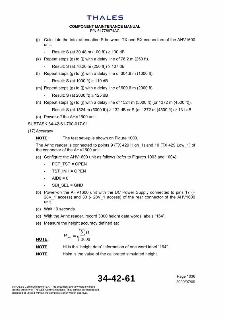
COMPONENT MAINTENANCE MANUAL
P/N 61778974AC
34-42-61 Page 1036
2009/07/09©THALES Communications S.A. This document and any data included are the property of THALES Communications. They cannot be reproduced, disclosed or utilised without the company's prior written approval.
(j) Calculate the total attenuation S between TX and RX connectors of the AHV1600 unit.
- Result: S (at 30.48 m (100 ft)) 100 dB
(k) Repeat steps (g) to (j) with a delay line of 76.2 m (250 ft).
- Result: S (at 76.20 m (250 ft)) 107 dB
(l) Repeat steps (g) to (j) with a delay line of 304.8 m (1000 ft).
- Result: S (at 1000 ft) 119 dB
(m) Repeat steps (g) to (j) with a delay line of 609.6 m (2000 ft).
- Result: S (at 2000 ft) 125 dB
(n) Repeat steps (g) to (j) with a delay line of 1524 m (5000 ft) (or 1372 m (4500 ft)).
- Result: S (at 1524 m (5000 ft)) 132 dB or S (at 1372 m (4500 ft)) 131 dB
(o) Power-off the AHV1600 unit.
SUBTASK 34-42-61-700-017-01
(17) Accuracy
NOTE: The test set-up is shown on Figure 1003.
The Arinc reader is connected to points 9 (TX 429 High_1) and 10 (TX 429 Low_1) of the connector of the AHV1600 unit.
(a) Configure the AHV1600 unit as follows (refer to Figures 1003 and 1004):
- FCT_TST = OPEN
- TST_INH = OPEN
- AID0 = 0
- SDI_SEL = GND
(b) Power-on the AHV1600 unit with the DC Power Supply connected to pins 17 (+ 28V_1 access) and 30 (- 28V_1 access) of the rear connector of the AHV1600 unit.
(c) Wait 10 seconds.
(d) With the Arinc reader, record 3000 height data words labels “164”.
(e) Measure the height accuracy defined as:
NOTE: 3000 i
mes
HH
NOTE: Hi is the “height data” information of one word label “164”.
NOTE: Hsim is the value of the calibrated simulated height.

COMPONENT MAINTENANCE MANUAL
P/N 61778974AC
34-42-61 Page 1037
2009/07/09©THALES Communications S.A. This document and any data included are the property of THALES Communications. They cannot be reproduced, disclosed or utilised without the company's prior written approval.
- Result: 2ft H - sim mesH
(f) Check the percentage of “height data” information (among 3000) in the tolerance 1.83 m (6 ft) 0.61 m (2 ft).
- Result: Percentage 95.4%
(g) Measure the height standard deviation Sd defined as:
3000
-
2 mesid
HHS
- Result: Sd < 0.61 m (2 ft)
(h) Measure the height absolute deviation Sabs defined as:
3000
- mesi
abs
HHS
- Result: Sabs < 1.52 m (5 ft)
(i) Adjust the total loop attenuation (with the variable attenuators) to obtain 56 dB 1 dB of attenuation between Tx and Rx connectors of the AHV1600 unit.
(j) With the Arinc reader, record 3000 height data words labels “164”.
(k) Measure the height accuracy.
- Result: ft) (2 m 0.61 H- sim mesH
(l) Between points A and B of the test set-up is shown on Figure 1003, insert a delay line of 30.48 m (100 ft).
(m) Adjust the total loop attenuation (with the variable attenuators) to obtain 100 dB 1 dB of attenuation between Tx and Rx connectors of the AHV1600 unit.
(n) With the Arinc reader, record 3000 height data words labels “164”.
(o) Measure the height accuracy.
- Result: ft) (4 m 1.22 H- sim mesH
(p) Check the percentage of “height data” information (among 3000) in the tolerance 30.48 m (100 ft) 1.22 m (4 ft).
- Result: Percentage 95.4%
(q) Measure the height standard deviation Sd:
- Result: Sd < 0.61 m (2 ft)
(r) Measure the height absolute deviation Sabs:
- Result: Sabs < 1.52 m (5 ft)

COMPONENT MAINTENANCE MANUAL
P/N 61778974AC
34-42-61 Page 1038
2009/07/09©THALES Communications S.A. This document and any data included are the property of THALES Communications. They cannot be reproduced, disclosed or utilised without the company's prior written approval.
(s) Adjust the total loop attenuation (with the variable attenuators) to obtain 80 dB 1 dB of attenuation between Tx and Rx connectors of the AHV1600 unit.
(t) With the Arinc reader, record 3000 height data words labels “164”.
(u) Measure the height accuracy.
- Result: ft) (4 m 1.22 H- sim mesH
(v) Repeat steps (l) to (o) with a delay line of 76.20 m (250 ft) and a total loop attenuation of 108 dB 1 dB.
- Result: ft) (7 m 2.13 H- sim mesH
(w) Repeat step (p) and take into account the tolerance 76.20 m (250 ft) 2.13 m (7 ft).
- Result: Percentage 95.4%
(x) Repeat step (q).
- Result: Sd < 0.37 m (1.2 ft)
(y) Repeat steps (s) to (u) with a total loop attenuation of 88 dB 1 dB.
- Result: ft) (7 m 2.13 H- sim mesH
(z) Repeat steps (l) to (o) with a delay line of 304.8 m (1000 ft) and a total loop attenuation of 118 dB 1 dB.
- Result: ft) (22 m 6.71 H- sim mesH
(aa) Repeat step (p) and take into account the tolerance 304.8 m (1000 ft) 6.71 m (22 ft).
- Result: Percentage 95.4%
(bb) Repeat step (q).
- Result: Sd < 1.52 m (5 ft)
(cc) Repeat steps (s) to (u) with a total loop attenuation of 98 dB 1 dB.
- Result: ft) (22 m 6.71 H- sim mesH
(dd) Repeat steps (l) to (o) with a delay line of 609.6 m (2000 ft) and a total loop attenuation of 124 dB 1 dB.
- Result: ft) (42 m 12.80 H- sim mesH
(ee) Repeat step (p) and take into account the tolerance 609.6 m (2000 ft) 12.80 m (42 ft).
- Result: Percentage 95.4%

COMPONENT MAINTENANCE MANUAL
P/N 61778974AC
34-42-61 Page 1039
2009/07/09©THALES Communications S.A. This document and any data included are the property of THALES Communications. They cannot be reproduced, disclosed or utilised without the company's prior written approval.
(ff) Repeat step (q).
- Result: Sd < 3.05 m (10 ft)
(gg) Repeat steps (s) to (u) with a total loop attenuation of 104 dB 1 dB.
- Result: ft) (42 m 12.80 H- sim mesH
(hh) Repeat steps (l) to (o) with a delay line of 1524 m (5000 ft) (or 1372 m (4500 ft)) and a total loop attenuation of 132 dB 1 dB.
- Result: ft) (102 m 31.09 H- sim mesH (or
ft) (4500 m 1372for ft) (92 m 28.04 H- sim mesH )
(ii) Repeat step (p) and take into account the tolerance 1524 m (5000 ft) 31.09 m (102 ft) (or 1372 m (4500 ft) 28.04 m (92 ft)).
- Result: Percentage 95.4%
(jj) Repeat step (q).
- Result: Sd < 7.62 m (25 ft) (or Sd < 6.86 m (22.5 ft) for 1372 m (4500 ft))
(kk) Repeat steps (s) to (u) with a total loop attenuation of 112 dB 1 dB.
- Result: ft) (102 m 31.09 H- sim mesH (or
ft) (4500 m 1372for ft) (92 m 28.04 H- sim mesH )
(ll) Power-off the AHV1600 unit.
SUBTASK 34-42-61-700-018-01
(18) Response time performance during a height step
NOTE: The test set-up is shown on Figure 1003.
The Arinc reader is connected to points 9 (TX 429 High_1) and 10 (TX 429 Low_1) of the connector of the AHV1600 unit.
(a) Configure the AHV1600 unit as follows (refer to Figures 1003 and 1004):
- FCT_TST = OPEN
- TST_INH = OPEN
- AID0 = 0
- SDI_SEL = GND
(b) Between points A and B of the test set-up is shown on Figure 1003, insert a delay line of 30.48 m (100 ft).
(c) Adjust the total loop attenuation (with the variable attenuators) to obtain 100 dB 1 dB of attenuation between Tx and Rx connectors of the AHV1600 unit.
COMPONENT MAINTENANCE MANUAL
P/N 61778974AC
34-42-61 Page 1040
2009/07/09©THALES Communications S.A. This document and any data included are the property of THALES Communications. They cannot be reproduced, disclosed or utilised without the company's prior written approval.
(d) Power-on the AHV1600 unit with the DC Power Supply connected to pins 17 (+ 28V_1 access) and 30 (- 28V_1 access) of the rear connector of the AHV1600unit.
(e) Wait 10 seconds.
(f) With the Arinc reader, start a recording of the height data words labels “164”.
(g) Wait 5 seconds and between points A and B of the test set-up is shown on Figure 1003, insert a delay line of 36.58 m (120 ft) to simulate a height step (the height step must be effective in a maximum time duration of 40ms).
(h) Wait 5 seconds.
(i) Stop the recording of the height data words labels “164”.
(j) Check the “height data” response time T to reach 63% of the height step.
NOTE: 63% of the height step is equal to 3.84 m (12.6 ft) (the height step is 6.10 m (20 ft)).
- Result: (0.1s T 0.25s)
(k) Check that the “status matrix” information of the height data words labels “164 doesn’t change during the height step and stays to “NO” state.
- Result: bit 30 = 1 bit 31 = 1
(l) Power-off the AHV1600 unit.
SUBTASK 34-42-61-700-019-01
(19) Operation at + 22 V and + 18 V
NOTE: The test set-up is shown on Figure 1003.
The Arinc reader is connected to points 9 (TX 429 High_1) and 10 (TX 429 Low_1) of the connector of the AHV1600 unit.
(a) Configure the AHV1600 unit as follows (refer to Figures 1003 and 1004):
- FCT_TST = OPEN
- TST_INH = OPEN
- AID0 = 0
- SDI_SEL = GND
(b) Adjust the output voltage of the DC Power Supply to + 22 VDC 0.1 VDC.
(c) Power-on the AHV1600 unit with the DC Power Supply connected to pins 17 (+ 28V_1 access) and 30 (- 28V_1 access) of the rear connector of the AHV1600 unit.
(d) Wait 10 seconds.
(e) Measure the value Ic of the DC current on the milliammeter.
- Result: Ic 0.913A

COMPONENT MAINTENANCE MANUAL
P/N 61778974AC
34-42-61 Page 1041
2009/07/09©THALES Communications S.A. This document and any data included are the property of THALES Communications. They cannot be reproduced, disclosed or utilised without the company's prior written approval.
(f) Power-off the AHV1600 unit.
(g) Disconnect the ammeter (the positive output of the DC power supply is directly connected to the pin 17 (+ 28V_1 access) of the rear connector of the AHV1600 unit).
(h) Connect the current probe to the wire linked to the pin 17 (+ 28V_1 access) and do the test set-up shown on Figure 1005.
(i) Calibrate the digital oscilloscope in triggered single shot on the rising slope of the current probe.
(j) Power-on the AHV1600.
(k) On the digital oscilloscope, check the peak pulse current value I at power-up.
- Result: I < 30APeak
(l) On the digital oscilloscope, check the time duration Td for the in-rush current reaches 63% of the peak pulse value.
- Result: t 500s
(m) Power-off the AHV1600 unit.
(n) Adjust the output voltage of the DC Power Supply to + 18 VDC 0.1 VDC.
(o) Power-on the AHV1600 unit with the DC Power Supply connected to pins 17 and 30 of the rear connector of the AHV1600 unit.
(p) Wait 10 seconds.
(q) Measure the value Ic of the DC current on the milliammeter.
- Result: Ic 1.117 A
(r) Adjust the total loop attenuation (with the variable attenuators) to obtain the maximum attenuation between Tx and Rx connectors of the AHV1600 unit.
(s) On the RF spectrum analyzer, measure the low transmitted Radio Frequency Fmin.
- Result: Fmin 4.2 GHz
(t) On the RF spectrum analyzer, measure the high transmitted Radio Frequency Fmax.
- Result: Fmax 4.4 GHz
(u) Slowly, decrease the total loop attenuation until the AHV1600 unit switchovers to “NO” state (on height data words labels “164”, bit 30 = 1 and bit 31 = 1).
(v) Calculate the total attenuation S between TX and RX connectors of the AHV1600 unit.
- Result: 77 dB S (at 1.83 m (6 ft)) 86 dB
(w) Adjust the total loop attenuation (with the variable attenuators) to obtain 76 dB 1 dB of attenuation between Tx and Rx connectors of the AHV1600 unit.

COMPONENT MAINTENANCE MANUAL
P/N 61778974AC
34-42-61 Page 1042
2009/07/09©THALES Communications S.A. This document and any data included are the property of THALES Communications. They cannot be reproduced, disclosed or utilised without the company's prior written approval.
(x) With the Arinc reader, record 3000 height data words labels “164”.
(y) Measure the height accuracy defined as:
NOTE: 3000 i
mes
HH
NOTE: Hi is the “height data” information of one word label “164”
NOTE: Hsim is the value of the calibrated simulated height
- Result: ft) (2 m 0.61 H- sim mesH
(z) Check the percentage of “height data” information (among 3000) in the tolerance 1.83 m (6 ft) 0.61 m (2 ft).
- Result: Percentage 95.4%
(aa) Measure the height standard deviation Sd defined as:
3000
-
2 mesid
HHS
- Result: Sd < 0.61 m (2 ft)
(bb) Measure the height absolute deviation Sabs defined as:
3000
- mesi
abs
HHS
- Result: Sabs < 1.52 m (5 ft)
(cc) On the RF Power meter, read the value P1 and calculate P according to the attenuation A (between TX connector of the ERT560 and the probe of the RF Power meter). P(dBm) = P1(dBm) + A(dB).
- Result: P = 4 dBm 2 dB
(dd) Between points A and B of the test set-up is shown on Figure 1003, insert a delay line of 1524 m (5000 ft) (or 1372 m (4500 ft)).
(ee) Adjust the total loop attenuation (with the variable attenuators) to obtain the maximum attenuation between Tx and Rx connectors of the AHV1600 unit.
(ff) Slowly, decrease the total loop attenuation until the AHV1600 unit switchovers to “NO” state (on height data words labels “164”, bit 30 = 1 and bit 31 = 1).
(gg) Calculate the total attenuation S between TX and RX connectors of the AHV1600 unit.
- Result: S (at 1524 m (5000 ft)) 132 dB or S (at 1372 m (4500 ft)) 132 dB
(hh) Adjust the total loop attenuation (with the variable attenuators) to obtain 132 dB 1 dB of attenuation between Tx and Rx connectors of the AHV1600 unit.
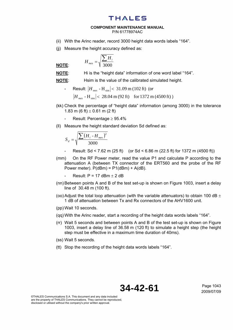
COMPONENT MAINTENANCE MANUAL
P/N 61778974AC
34-42-61 Page 1043
2009/07/09©THALES Communications S.A. This document and any data included are the property of THALES Communications. They cannot be reproduced, disclosed or utilised without the company's prior written approval.
(ii) With the Arinc reader, record 3000 height data words labels “164”.
(jj) Measure the height accuracy defined as:
NOTE: 3000 i
mes
HH
NOTE: Hi is the “height data” information of one word label “164”.
NOTE: Hsim is the value of the calibrated simulated height.
- Result: ft) (102 m 31.09 H- sim mesH (or
ft) (4500 m 1372for ft) (92 m 28.04 H- sim mesH )
(kk) Check the percentage of “height data” information (among 3000) in the tolerance 1.83 m (6 ft) 0.61 m (2 ft)
- Result: Percentage 95.4%
(ll) Measure the height standard deviation Sd defined as:
3000
-
2 mesid
HHS
- Result: Sd < 7.62 m (25 ft) (or Sd < 6.86 m (22.5 ft) for 1372 m (4500 ft))
(mm) On the RF Power meter, read the value P1 and calculate P according to the attenuation A (between TX connector of the ERT560 and the probe of the RF Power meter). P(dBm) = P1(dBm) + A(dB).
- Result: P = 17 dBm 2 dB
(nn) Between points A and B of the test set-up is shown on Figure 1003, insert a delay line of 30.48 m (100 ft).
(oo) Adjust the total loop attenuation (with the variable attenuators) to obtain 100 dB 1 dB of attenuation between Tx and Rx connectors of the AHV1600 unit.
(pp) Wait 10 seconds.
(qq) With the Arinc reader, start a recording of the height data words labels “164”.
(rr) Wait 5 seconds and between points A and B of the test set-up is shown on Figure 1003, insert a delay line of 36.58 m (120 ft) to simulate a height step (the height step must be effective in a maximum time duration of 40ms).
(ss) Wait 5 seconds.
(tt) Stop the recording of the height data words labels “164”.

COMPONENT MAINTENANCE MANUAL
P/N 61778974AC
34-42-61 Page 1044
2009/07/09©THALES Communications S.A. This document and any data included are the property of THALES Communications. They cannot be reproduced, disclosed or utilised without the company's prior written approval.
(uu) Check the “height data” response time T to reach 63% of the height step.
NOTE: 63% of the height step is equal to 3.84 m (12.6 ft) (the height step is 6.10 m (20 ft)).
- Result: (0.1s T 0.25s)
(vv) Check that the “status matrix” information of the height data words labels “164 doesn’t change during the height step and stays to “NO” state.
- Result: bit 30 = 1 bit 31 = 1
(ww) Power-off the AHV1600 unit.
SUBTASK 34-42-61-700-020-01
(20) Operation at + 30.3 V
NOTE: The test set-up is shown on Figure 1003.
The Arinc reader is connected to points 9 (TX 429 High_1) and 10 (TX 429 Low_1) of the connector of the AHV1600 unit.
(a) Configure the AHV1600 unit as follows (refer to Figures 1003 and 1004):
- FCT_TST = OPEN
- TST_INH = OPEN
- AID0 = 0
- SDI_SEL = GND
(b) Adjust the output voltage of the DC Power Supply to + 30.3 VDC 0.1 VDC.
(c) Power-on the AHV1600 unit with the DC Power Supply connected to pins 17 (+ 28V_1 access) and 30 (- 28V_1 access) of the rear connector of the AHV1600 unit.
(d) Wait 10 seconds.
(e) Measure the value Ic of the DC current on the milliammeter.
- Result: Ic 0.662A
(f) Power-off the AHV1600 unit.
(g) Disconnect the ammeter (the positive output of the DC power supply is directly connected to the pin 17 (+ 28V_1 access) of the rear connector of the AHV1600 unit).
(h) Connect the current probe to the wire linked to the pin 17 (+ 28V_1 access) and do the test set-up shown on Figure 1005.
(i) Calibrate the digital oscilloscope in triggered single shot on the rising slope of the current probe.
(j) Power-on the AHV1600.

COMPONENT MAINTENANCE MANUAL
P/N 61778974AC
34-42-61 Page 1045
2009/07/09©THALES Communications S.A. This document and any data included are the property of THALES Communications. They cannot be reproduced, disclosed or utilised without the company's prior written approval.
(k) On the digital oscilloscope, check the peak pulse current value I at power-up.
- Result: I < 22APeak
(l) On the digital oscilloscope, check the time duration Td for the in-rush current reaches 63% of the peak pulse value.
- Result: t 750s
(m) Power-off the AHV1600 unit.
(n) Remove the current probe.
(o) Power-on the AHV1600 unit.
(p) Wait 10 seconds.
(q) Adjust the total loop attenuation (with the variable attenuators) to obtain the maximum attenuation between Tx and Rx connectors of the AHV1600 unit.
(r) On the RF spectrum analyzer, measure the low transmitted Radio Frequency Fmin.
- Result: Fmin 4.2 GHz
(s) On the RF spectrum analyzer, measure the high transmitted Radio Frequency Fmax.
- Result: Fmax 4.4 GHz
(t) Slowly, decrease the total loop attenuation until the AHV1600 unit switchovers to “NO” state (on height data words labels “164”, bit 30 = 1 and bit 31 = 1).
(u) Calculate the total attenuation S between TX and RX connectors of the AHV1600 unit.
- Result: 74 dB S (at 1.83 m (6 ft)) 82 dB
(v) Adjust the total loop attenuation (with the variable attenuators) to obtain 76 dB 1 dB of attenuation between Tx and Rx connectors of the AHV1600 unit.
(w) With the Arinc reader, record 3000 height data words labels “164”.
(x) Measure the height accuracy defined as:
NOTE: 3000 i
mes
HH
NOTE: Hi is the “height data” information of one word label “164”.
NOTE: Hsim is the value of the calibrated simulated height.
- Result: ft) (2 m 0.61 H- sim mesH
(y) Check the percentage of “height data” information (among 3000) in the tolerance 1.83 m (6 ft) 0.61 m (2 ft).
- Result: Percentage 95.4%

COMPONENT MAINTENANCE MANUAL
P/N 61778974AC
34-42-61 Page 1046
2009/07/09©THALES Communications S.A. This document and any data included are the property of THALES Communications. They cannot be reproduced, disclosed or utilised without the company's prior written approval.
(z) Measure the height standard deviation Sd defined as:
3000
-
2 mesid
HHS
- Result: Sd < 0.61 m (2 ft)
(aa) Measure the height absolute deviation Sabs defined as:
3000
- mesi
abs
HHS
- Result: Sabs < 1.52 m (5 ft)
(bb) On the RF Power meter, read the value P1 and calculate P according to the attenuation A (between TX connector of the ERT560 and the probe of the RF Power meter). P(dBm) = P1(dBm) + A(dB).
- Result: P = 4 dBm 2 dB
(cc) Between points A and B of the test set-up is shown on Figure 1003, insert a delay line of 1524 m (5000 ft) (or 1372 m (4500 ft)).
(dd) Adjust the total loop attenuation (with the variable attenuators) to obtain the maximum attenuation between Tx and Rx connectors of the AHV1600 unit.
(ee) Slowly, decrease the total loop attenuation until the AHV1600 unit switchovers to “NO” state (on height data words labels “164”, bit 30 = 1 and bit 31 = 1).
(ff) Calculate the total attenuation S between TX and RX connectors of the AHV1600 unit.
- Result: S (at 1524 m (5000 ft)) 132 dB or S (at 1372 m (4500 ft)) 132 dB
(gg) Adjust the total loop attenuation (with the variable attenuators) to obtain 132 dB 1 dB of attenuation between Tx and Rx connectors of the AHV1600 unit.
(hh) With the Arinc reader, record 3000 height data words labels “164”.
(ii) Measure the height accuracy defined as:
NOTE: 3000 i
mes
HH
NOTE: Hi is the “height data” information of one word label “164”
NOTE: Hsim is the value of the calibrated simulated height
- Result: ft) (102 m 31.09 H- sim mesH (or
ft) (4500 m 1372for ft) (92 m 28.04 H- sim mesH )
(jj) Check the percentage of “height data” information (among 3000) in the tolerance 1.83 m (6 ft) 0.61 m (2 ft)

COMPONENT MAINTENANCE MANUAL
P/N 61778974AC
34-42-61 Page 1047
2009/07/09©THALES Communications S.A. This document and any data included are the property of THALES Communications. They cannot be reproduced, disclosed or utilised without the company's prior written approval.
- Result: Percentage 95.4%
(kk) Measure the height standard deviation Sd defined as:
3000
-
2 mesid
HHS
- Result: Sd < 7.62 m (25 ft) (or Sd < 6.86 m (22.5 ft) for 1372 m (4500 ft))
(ll) On the RF Power meter, read the value P1 and calculate P according to the attenuation A (between TX connector of the ERT560 and the probe of the RF Power meter). P(dBm) = P1(dBm) + A(dB).
- Result: P = 17 dBm 2 dB
(mm) Between points A and B of the test set-up is shown on Figure 1003, insert a delay line of 30.48 m (100 ft).
(nn) Adjust the total loop attenuation (with the variable attenuators) to obtain 100 dB 1 dB of attenuation between Tx and Rx connectors of the AHV1600 unit.
(oo) Wait 10 seconds.
(pp) With the Arinc reader, start a recording of the height data words labels “164”.
(qq) Wait 5 seconds and between points A and B of the test set-up is shown on Figure 1003, insert a delay line of 36.58 m (120 ft) to simulate a height step (the height step must be effective in a maximum time duration of 40ms).
(rr) Wait 5 seconds.
(ss) Stop the recording of the height data words labels “164”.
(tt) Check the “height data” response time T to reach 63% of the height step.
NOTE: 63% of the height step is equal to 3.84 m (12.6 ft) (the height step is 6.10 m (20 ft)).
- Result: (0.1s T 0.25s)
(uu) Check that the “status matrix” information of the height data words labels “164 doesn’t change during the height step and stays to “NO” state.
- Result: bit 30 = 1 bit 31 = 1
(vv) Power-off the AHV1600 unit.

COMPONENT MAINTENANCE MANUAL
P/N 61778974AC
34-42-61 Page 1048
2009/07/09©THALES Communications S.A. This document and any data included are the property of THALES Communications. They cannot be reproduced, disclosed or utilised without the company's prior written approval.
TASK 34-42-61-700-802-A01
5. TEST REPORT
A. INTRODUCTION
The test report below, is given as example.
B. TEST REPORT EXAMPLE
TABLE 34-42-61-992-114-A01
Lightning protection of the power supply inputs and Arinc outputs TEST
PROCEDURE CONDITIONS TOLERANCE RESULTS
- Between pins 17 and 2 (positive polarity) + 73.4 V Vpeak + 81.2 V
- Between pins 17 and 2 (negative polarity) - 81.2 V Vpeak - 73.4 V
- Between pins 30 and 2 (positive polarity) + 73.4 V Vpeak + 81.2 V
- Between pins 30 and 2 (negative polarity) - 81.2 V Vpeak - 73.4 V
- Between pins 18 and 2 (positive polarity) + 73.4 V Vpeak + 81.2 V
- Between pins 18 and 2 (negative polarity) - 81.2 V Vpeak - 73.4 V
- Between pins 19 and 2 (positive polarity) + 73.4 V Vpeak + 81.2 V
- Between pins 19 and 2 (negative polarity) - 81.2 V Vpeak - 73.4 V
- Between pins 9 and 2 (positive polarity) + 10.4 V Vpeak + 11.9 V
- Between pins 9 and 2 (negative polarity) - 11.9 V Vpeak - 10.4 V
- Between pins 10 and 2 (positive polarity) + 10.4 V Vpeak + 11.9 V
- Between pins 10 and 2 (negative polarity) - 11.9 V Vpeak - 10.4 V
- Between pins 13 and 2 (positive polarity) + 10.4 V Vpeak + 11.9 V
- Between pins 13 and 2 (negative polarity) - 11.9 V Vpeak - 10.4 V
- Between pins 14 and 2 (positive polarity) + 10.4 V Vpeak + 11.9 V
(1) refer to SUBTASK 34-42-61-700-001-01
- Between pins 14 and 2 (negative polarity) - 11.9 V Vpeak - 10.4 V
TABLE 34-42-61-992-115-A01

COMPONENT MAINTENANCE MANUAL
P/N 61778974AC
34-42-61 Page 1049
2009/07/09©THALES Communications S.A. This document and any data included are the property of THALES Communications. They cannot be reproduced, disclosed or utilised without the company's prior written approval.
Lightning protection of the Radio Frequency inputs “RX”, “TX” and discretes inputs TEST
PROCEDURE CONDITIONS TOLERANCE RESULTS
- Between central contact of RX antenna access and pin 2 (positive polarity)
+ 15.2 V Vlimit + 18.6V
- Between central contact of RX antenna access and pin 2 (negative polarity)
- 14.3 V Vlimit - 10.3V
- Between central contact of TX antenna access and pin 2 (positive polarity)
+ 15.2 V Vlimit + 18.6 V
- Between central contact of TX antenna access and pin 2 (negative polarity)
- 14.3 V Vlimit - 10.3 V
- Between pins 5 and 2 (positive polarity) + 36.8 V Vlimit + 42.8 V
- Between pins 5 and 2 (negative polarity) - 5.3 V Vlimit - 1.3 V
- Between pins 6 and 2 (positive polarity) + 36.8 V Vlimit + 42.8 V
- Between pins 6 and 2 (negative polarity) - 5.3 V Vlimit - 1.3 V
- Between pins 23 and 2 (positive polarity) + 36.8 V Vlimit + 42.8 V
- Between pins 23 and 2 (negative polarity) - 5.3 V Vlimit - 1.3 V
- Between pins 24 and 2 (positive polarity) + 36.8 V Vlimit + 42.8 V
- Between pins 24 and 2 (negative polarity) - 5.3 V Vlimit - 1.3 V
- Between pins 16 and 2 (positive polarity) + 36.8 V Vlimit + 42.8 V
- Between pins 16 and 2 (negative polarity) - 5.3 V Vlimit - 1.3 V
- Between pins 20 and 2 (positive polarity) + 36.8 V Vlimit + 42.8 V
- Between pins 20 and 2 (negative polarity) - 5.3 V Vlimit - 1.3 V
- Between pins 34 and 2 (positive polarity) + 36.8 V Vlimit + 42.8 V
(2) refer to SUBTASK 34-42-61-700-002-01
- Between pins 34 and 2 (negative polarity) - 5.3 V Vlimit - 1.3 V

COMPONENT MAINTENANCE MANUAL
P/N 61778974AC
34-42-61 Page 1050
2009/07/09©THALES Communications S.A. This document and any data included are the property of THALES Communications. They cannot be reproduced, disclosed or utilised without the company's prior written approval.
TABLE 34-42-61-992-116-A01
Power consumption TEST
PROCEDURE CONDITIONS TOLERANCE RESULTS
Value of the current (pin 17) Ic 0.727 A In-rush current (pin 17) I < 22 APeak Time duration to reach 63% (pin 17) Td 750 s
Value of the current (pin 18) Ic 0.727 A In-rush current (pin 18) I < 22 APeak
(4) refer to SUBTASK 34-42-61-700-004-01
Time duration to reach 63% (pin 18) Td 750 s
TABLE 34-42-61-992-117-A01
RF bandwidth TEST
PROCEDURE CONDITIONS TOLERANCE RESULTS
Low transmitted Radio Frequency Fmin 4.2 GHz (5) refer to SUBTASK 34-42-61-700-005-01 High transmitted Radio Frequency Fmax 4.4 GHz
TABLE 34-42-61-992-118-A01
RF transmitted power TEST
PROCEDURE CONDITIONS TOLERANCE RESULTS
For 1.83 m (6 ft) simulated height P = 4 dBm 2 dB For 30.48 m (100 ft) simulated height P = 5 dBm 2 dB
For 76.20 m (250 ft) simulated height P = 9 dBm 2 dB
For 304.8 m (1000 ft) simulated height P = 15 dBm 2 dB
For 609.6 m (2000 ft) simulated height P = 17 dBm 2 dB
(6) refer to SUBTASK 34-42-61-700-006-01
For 1524 m (5000 ft) (or 1372 m (4500 ft)) simulated height P = 17 dBm 2 dB
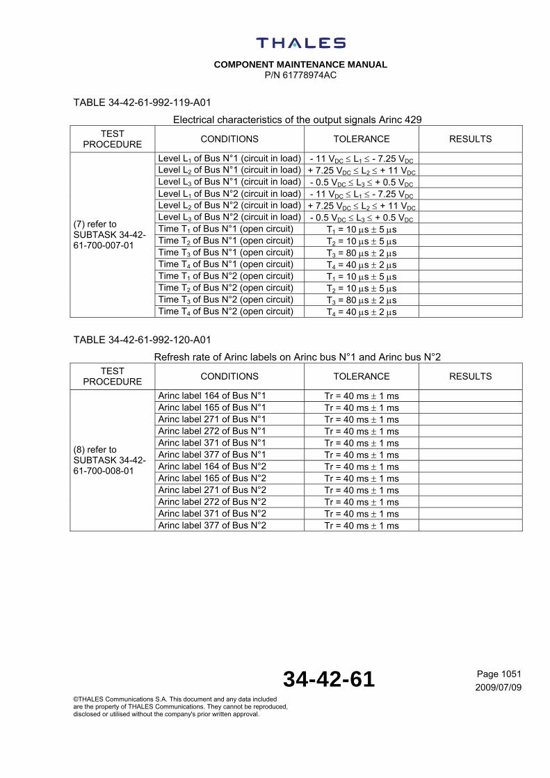
COMPONENT MAINTENANCE MANUAL
P/N 61778974AC
34-42-61 Page 1051
2009/07/09©THALES Communications S.A. This document and any data included are the property of THALES Communications. They cannot be reproduced, disclosed or utilised without the company's prior written approval.
TABLE 34-42-61-992-119-A01
Electrical characteristics of the output signals Arinc 429 TEST
PROCEDURE CONDITIONS TOLERANCE RESULTS
Level L1 of Bus N°1 (circuit in load) - 11 VDC L1 - 7.25 VDC Level L2 of Bus N°1 (circuit in load) + 7.25 VDC L2 + 11 VDC Level L3 of Bus N°1 (circuit in load) - 0.5 VDC L3 + 0.5 VDC Level L1 of Bus N°2 (circuit in load) - 11 VDC L1 - 7.25 VDC Level L2 of Bus N°2 (circuit in load) + 7.25 VDC L2 + 11 VDC Level L3 of Bus N°2 (circuit in load) - 0.5 VDC L3 + 0.5 VDC Time T1 of Bus N°1 (open circuit) T1 = 10 s 5 s Time T2 of Bus N°1 (open circuit) T2 = 10 s 5 s Time T3 of Bus N°1 (open circuit) T3 = 80 s 2 s Time T4 of Bus N°1 (open circuit) T4 = 40 s 2 s Time T1 of Bus N°2 (open circuit) T1 = 10 s 5 s Time T2 of Bus N°2 (open circuit) T2 = 10 s 5 s Time T3 of Bus N°2 (open circuit) T3 = 80 s 2 s
(7) refer to SUBTASK 34-42-61-700-007-01
Time T4 of Bus N°2 (open circuit) T4 = 40 s 2 s
TABLE 34-42-61-992-120-A01
Refresh rate of Arinc labels on Arinc bus N°1 and Arinc bus N°2 TEST
PROCEDURE CONDITIONS TOLERANCE RESULTS
Arinc label 164 of Bus N°1 Tr = 40 ms 1 ms Arinc label 165 of Bus N°1 Tr = 40 ms 1 ms Arinc label 271 of Bus N°1 Tr = 40 ms 1 ms Arinc label 272 of Bus N°1 Tr = 40 ms 1 ms Arinc label 371 of Bus N°1 Tr = 40 ms 1 ms Arinc label 377 of Bus N°1 Tr = 40 ms 1 ms Arinc label 164 of Bus N°2 Tr = 40 ms 1 ms Arinc label 165 of Bus N°2 Tr = 40 ms 1 ms Arinc label 271 of Bus N°2 Tr = 40 ms 1 ms Arinc label 272 of Bus N°2 Tr = 40 ms 1 ms Arinc label 371 of Bus N°2 Tr = 40 ms 1 ms
(8) refer to SUBTASK 34-42-61-700-008-01
Arinc label 377 of Bus N°2 Tr = 40 ms 1 ms
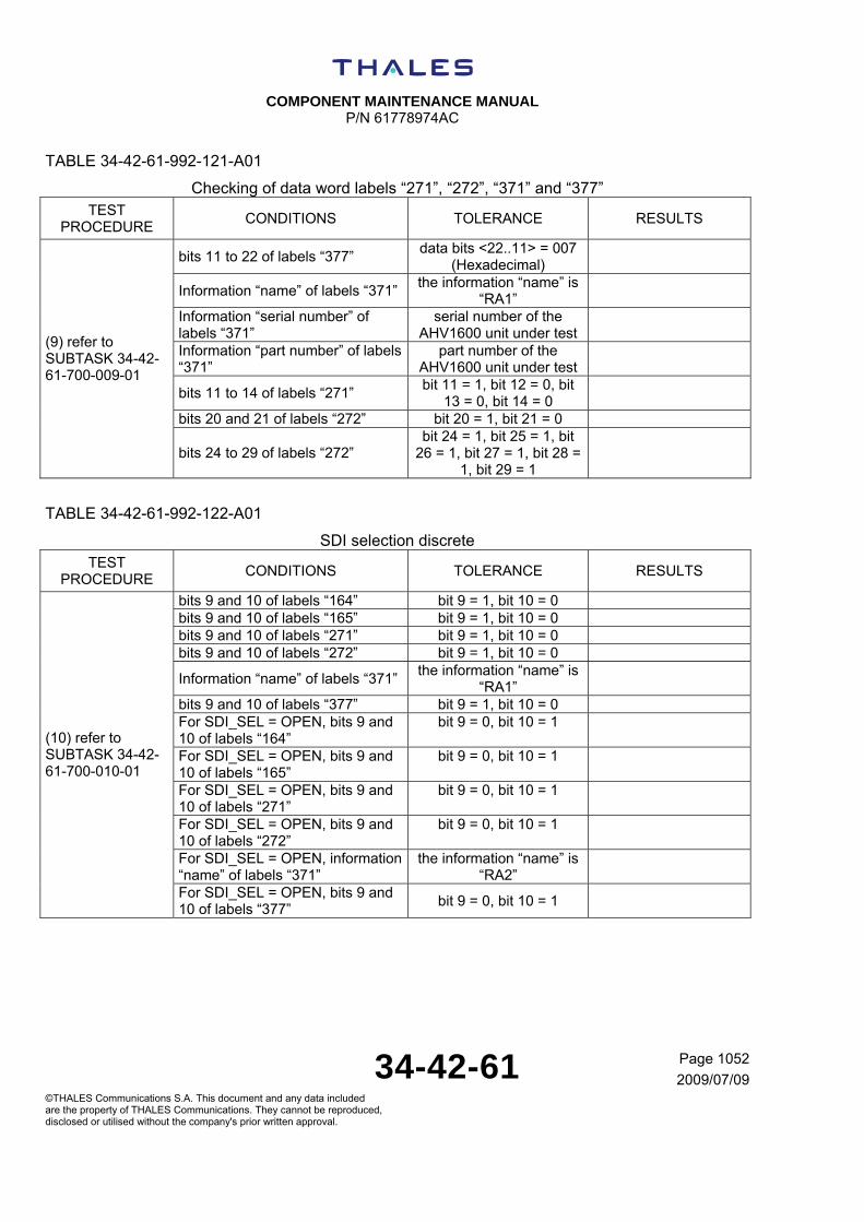
COMPONENT MAINTENANCE MANUAL
P/N 61778974AC
34-42-61 Page 1052
2009/07/09©THALES Communications S.A. This document and any data included are the property of THALES Communications. They cannot be reproduced, disclosed or utilised without the company's prior written approval.
TABLE 34-42-61-992-121-A01
Checking of data word labels “271”, “272”, “371” and “377” TEST
PROCEDURE CONDITIONS TOLERANCE RESULTS
bits 11 to 22 of labels “377” data bits <22..11> = 007
(Hexadecimal)
Information “name” of labels “371” the information “name” is
“RA1”
Information “serial number” of labels “371”
serial number of the AHV1600 unit under test
Information “part number” of labels “371”
part number of the AHV1600 unit under test
bits 11 to 14 of labels “271” bit 11 = 1, bit 12 = 0, bit
13 = 0, bit 14 = 0
bits 20 and 21 of labels “272” bit 20 = 1, bit 21 = 0
(9) refer to SUBTASK 34-42-61-700-009-01
bits 24 to 29 of labels “272” bit 24 = 1, bit 25 = 1, bit
26 = 1, bit 27 = 1, bit 28 = 1, bit 29 = 1
TABLE 34-42-61-992-122-A01
SDI selection discrete TEST
PROCEDURE CONDITIONS TOLERANCE RESULTS
bits 9 and 10 of labels “164” bit 9 = 1, bit 10 = 0 bits 9 and 10 of labels “165” bit 9 = 1, bit 10 = 0 bits 9 and 10 of labels “271” bit 9 = 1, bit 10 = 0 bits 9 and 10 of labels “272” bit 9 = 1, bit 10 = 0
Information “name” of labels “371” the information “name” is
“RA1”
bits 9 and 10 of labels “377” bit 9 = 1, bit 10 = 0 For SDI_SEL = OPEN, bits 9 and 10 of labels “164”
bit 9 = 0, bit 10 = 1
For SDI_SEL = OPEN, bits 9 and 10 of labels “165”
bit 9 = 0, bit 10 = 1
For SDI_SEL = OPEN, bits 9 and 10 of labels “271”
bit 9 = 0, bit 10 = 1
For SDI_SEL = OPEN, bits 9 and 10 of labels “272”
bit 9 = 0, bit 10 = 1
For SDI_SEL = OPEN, information “name” of labels “371”
the information “name” is “RA2”
(10) refer to SUBTASK 34-42-61-700-010-01
For SDI_SEL = OPEN, bits 9 and 10 of labels “377”
bit 9 = 0, bit 10 = 1

COMPONENT MAINTENANCE MANUAL
P/N 61778974AC
34-42-61 Page 1053
2009/07/09©THALES Communications S.A. This document and any data included are the property of THALES Communications. They cannot be reproduced, disclosed or utilised without the company's prior written approval.
TABLE 34-42-61-992-123-A01
Test Inhibit discrete TEST
PROCEDURE CONDITIONS TOLERANCE RESULTS
bit 11 of labels “164” bit 11 = 0 bit 18 of labels “271” bit 18 = 1 For TST_INH = GND, bit 11 of labels “164”
bit 11 = 1
(11) refer to SUBTASK 34-42-61-700-011-01
For TST_INH = GND, bit 18 of labels “271”
bit 18 = 0
TABLE 34-42-61-992-124-A01
Functional Test discrete TEST
PROCEDURE CONDITIONS TOLERANCE RESULTS
bit 19 of labels “272” bit 19 = 1 bit 17 of labels “271” bit 17 = 1
For FCT_TST = GND, bit 19 of labels “272”
bit 19 = 0 in maximum time duration of 3
seconds
(12) refer to SUBTASK 34-42-61-700-012-01
For FCT_TST = GND, bit 17 of labels “271”
bit 17 = 0
TABLE 34-42-61-992-125-A01
Search mode and track mode TEST
PROCEDURE CONDITIONS TOLERANCE RESULTS
For maximum attenuation, bits 30 and 31 of labels “164”
bit 30 = 1, bit 31 = 0
For maximum attenuation, information “height data” of labels “164”
Height data information = 2496.883 m (8191.875 ft)
For maximum attenuation, bits 30 and 31 of labels “165”
bit 30 = 1, bit 31 = 0
For maximum attenuation, information “height data” of labels “165”
Height data information = 2438.37 m (7999.9 ft)
For maximum attenuation, bits 17 and 18 of labels “272”
bit 17 = 0, bit 18 = 0
bits 30 and 31 of labels “164” bit 30 = 1, bit 31 = 1
Information “height data” of labels “164”
Height data information = 1.83 m (6 ft) 0.61 m
(2 ft)
(13) refer to SUBTASK 34-42-61-700-013-01
bits 30 and 31 of labels “165” bit 30 = 0, bit 31 = 0

COMPONENT MAINTENANCE MANUAL
P/N 61778974AC
34-42-61 Page 1054
2009/07/09©THALES Communications S.A. This document and any data included are the property of THALES Communications. They cannot be reproduced, disclosed or utilised without the company's prior written approval.
Information “height data” of labels “165”
Height data information = 1.83 m (6 ft) 0.61 m
(2 ft)
bits 30 and 31 of labels “271” bit 30 = 0, bit 31 = 0 bits 30 and 31 of labels “272” bit 30 = 0, bit 31 = 0 bits 30 and 31 of labels “377” bit 30 = 0, bit 31 = 0
TABLE 34-42-61-992-126-A01
Antenna failure TEST
PROCEDURE CONDITIONS TOLERANCE RESULTS
For TX antenna failure, bits 30 and 31 of labels “164”
bit 30 = 0, bit 31 = 0
For TX antenna failure, information “height data” of labels “164”
Height data information = 2496.883 m (8191.875 ft)
For TX antenna failure, bits 24 to 29 of labels “272”
bit 24 = 1, bit 25 = 1, bit 26 = 1, bit 27 = 1, bit 28 =
1, bit 29 = 0
For TX antenna failure, bits 30 and 31 of labels “272”
bit 30 = 1, bit 31 = 1
For TX antenna failure, bits 30 and 31 of labels “271”
bit 30 = 1, bit 31 = 1
For TX antenna failure, bits 30 and 31 of labels “377”
bit 30 = 1, bit 31 = 1
For TX antenna failure, stop transmitting of labels “165”
stop transmitting of labels “165” = OK
(14) refer to SUBTASK 34-42-61-700-014-01
For TX and RX antenna failure, bits 24 to 29 of labels “272”
bit 24 = 1, bit 25 = 1, bit 26 = 1, bit 27 = 1, bit 28 =
0, bit 29 = 0

COMPONENT MAINTENANCE MANUAL
P/N 61778974AC
34-42-61 Page 1055
2009/07/09©THALES Communications S.A. This document and any data included are the property of THALES Communications. They cannot be reproduced, disclosed or utilised without the company's prior written approval.
TABLE 34-42-61-992-127-A01
Built In Test function TEST
PROCEDURE CONDITIONS TOLERANCE RESULTS
bit 19 of labels “272” bit 19 = 1 For FCT_TST = GND and TST_INH = GND, bit 19 of labels “272”
bit 19 = 1
For FCT_TST = GND and TST_INH = OPEN, bit 19 of labels “272”
bit 19 = 0 (in maximum time duration of 3
seconds)
For FCT_TST = GND and TST_INH = OPEN, information “status matrix” and “height data” of labels “164”
bit 30 = 0, bit 31 = 1 Height data information =
30.48 m (100 ft) (in maximum time duration of
3 seconds)
(15) refer to SUBTASK 34-42-61-700-015-01
For FCT_TST = GND and TST_INH = OPEN, information “status matrix” and “height data” of labels “165”
bit 30 = 0, bit 31 = 1 Height data information =
30.48 m (100 ft) (in maximum time duration of
3 seconds)
TABLE 34-42-61-992-128-A01
Sensitivity TEST
PROCEDURE CONDITIONS TOLERANCE RESULTS
For 1.83 m (6 ft) simulated height 76 dB S (at 1.83 m
(6 ft)) 84 dB
For 30.48 m (100 ft) simulated height
S (at 30.48 m (100 ft)) 100 dB
For 76.20 m (250 ft) simulated height
S (at 76.20 m (250 ft)) 107 dB
For 304.8 m (1000 ft) simulated height
S (at 304.8 m (1000 ft)) 119 dB
For 609.6 m (2000 ft) simulated height
S (at 609.6 m (2000 ft)) 125 dB
(16) refer to SUBTASK 34-42-61-700-016-01
For 1524 m (5000 ft) (or 1372 m (4500 ft)) simulated height
S (at 1524 m (5000 ft)) 132 dB or S (at 1372 m
(4500 ft)) 131 dB

COMPONENT MAINTENANCE MANUAL
P/N 61778974AC
34-42-61 Page 1056
2009/07/09©THALES Communications S.A. This document and any data included are the property of THALES Communications. They cannot be reproduced, disclosed or utilised without the company's prior written approval.
TABLE 34-42-61-992-129-A01
Height accuracy TEST
PROCEDURE CONDITIONS TOLERANCE RESULTS
For 1.83 m (6 ft) simulated height and 0 = - 20 dB
|Hmes – Hsim| < 0.61 m (2 ft)
For 1.83 m (6 ft) simulated height and 0 = - 20 dB
Percentage > 95.4%
For 1.83 m (6 ft) simulated height and 0 = - 20 dB
Sd < 0.61 m (2 ft)
For 1.83 m (6 ft) simulated height and 0 = - 20 dB
Sabs < 1.52 m (5 ft)
For 1.83 m (6 ft) simulated height and 0 = 0 dB
|Hmes – Hsim| < 0.61 m (2 ft)
For 30.48 m (100 ft) simulated height and 0 = - 20 dB
|Hmes – Hsim| = < 1.22 m (4 ft)
For 30.48 m (100 ft) simulated height and 0 = - 20 dB
Percentage > 95.4%
For 30.48 m (100 ft) simulated height and 0 = - 20 dB
Sd < 0.61 m (2 ft)
For 30.48 m (100 ft) simulated height and 0 = - 20 dB
Sabs < 1.52 m (5 ft)
For 30.48 m (100 ft) simulated height and 0 = 0 dB
|Hmes – Hsim| < 1.22 m (4 ft)
For 76.20 m (250 ft) simulated height and 0 = - 20 dB
|Hmes – Hsim| < 2.13 m (7 ft)
For 76.20 m (250 ft) simulated height and 0 = - 20 dB
Percentage > 95.4%
For 76.20 m (250 ft) simulated height and 0 = - 20 dB
Sd < 0.37 m (1.2 ft)
For 76.20 m (250 ft) simulated height and 0 = 0 dB
|Hmes – Hsim| < 2.13 m (7 ft)
For 304.8 m (1000 ft) simulated height and 0 = - 20 dB
|Hmes – Hsim| < 6.71 m (22 ft)
For 304.8 m (1000 ft) simulated height and 0 = - 20 dB
Percentage > 95.4%
For 304.8 m (1000 ft) simulated height and 0 = - 20 dB
Sd < 1.52 m (5 ft)
For 304.8 m (1000 ft) simulated height and 0 = 0 dB
|Hmes – Hsim| < 6.71 m (22 ft)
(17) refer to SUBTASK 34-42-61-700-017-01
For 609.6 m (2000 ft) simulated height and 0 = - 20 dB
|Hmes – Hsim| < 12.80 m (42 ft)

COMPONENT MAINTENANCE MANUAL
P/N 61778974AC
34-42-61 Page 1057
2009/07/09©THALES Communications S.A. This document and any data included are the property of THALES Communications. They cannot be reproduced, disclosed or utilised without the company's prior written approval.
For 609.6 m (2000 ft) simulated height and 0 = - 20 dB
Percentage > 95.4%
For 609.6 m (2000 ft) simulated height and 0 = - 20 dB
Sd < 3.05 m (10 ft)
For 609.6 m (2000 ft) simulated height and 0 = 0 dB
|Hmes – Hsim| < 12.80 m (42 ft)
For 1524 m (5000 ft) (or 1372 m (4500 ft)) simulated height and 0 = - 20 dB
|Hmes – Hsim| < 31.09 m (102 ft)
(or |Hmes – Hsim| < 28.04 m (92 ft) for 1372 m (4500 ft))
For 1524 m (5000 ft) (or 1372 m (4500 ft)) simulated height and 0 = - 20 dB
Percentage > 95.4%
For 1524 m (5000 ft) (or 1372 m (4500 ft)) simulated height and 0 = - 20 dB
Sd < 7.62 m (25 ft) (or Sd < 6.86 m (22.5 ft) for
1372 m (4500 ft))
For 1524 m (5000 ft) (or 1372 m (4500 ft)) simulated height and 0 = 0 dB
|Hmes – Hsim| < 31.09 m (102 ft)
(or |Hmes – Hsim| < 28.04 m (92 ft) for 1372 m (4500 ft))
TABLE 34-42-61-992-130-A01
Response time performance during a height step TEST
PROCEDURE CONDITIONS TOLERANCE RESULTS
Height step is 6.10 m (20 ft) (0.1 s T 0.25 s) (18) refer to SUBTASK 34-42-61-700-018-01
During height step, bits 30 and 31 of labels “164”
bit 30 = 1, bit 31 = 1
TABLE 34-42-61-992-131-A01
Operation at +22V and +18V TEST
PROCEDURE CONDITIONS TOLERANCE RESULTS
Output voltage of the DC Power Supply (connected to pins 17 and 30) is adjusted to + 22 VDC 0.1 VDC
Ic 0.913 A
In-rush current on the pin 17 (output voltage of the DC Power Supply is adjusted to + 22 VDC 0.1 VDC)
I < 30 APeak
(19) refer to SUBTASK 34-42-61-700-019-01
Time duration to reach 63% of the peak pulse value (output voltage of the DC Power Supply is adjusted to + 22 VDC 0.1 VDC)
t 500 s
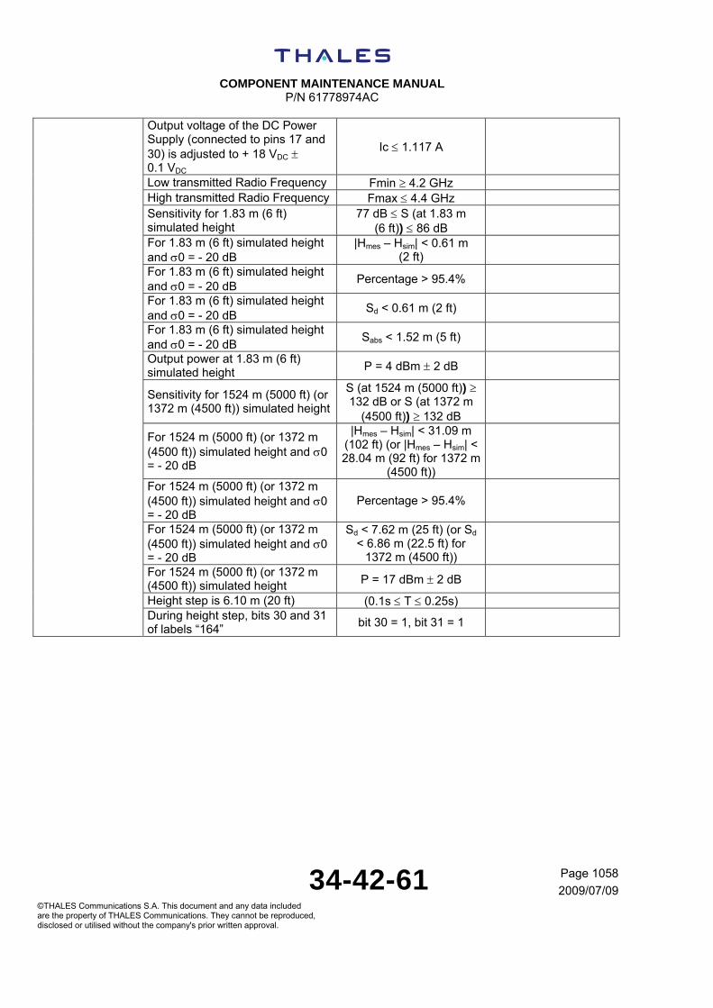
COMPONENT MAINTENANCE MANUAL
P/N 61778974AC
34-42-61 Page 1058
2009/07/09©THALES Communications S.A. This document and any data included are the property of THALES Communications. They cannot be reproduced, disclosed or utilised without the company's prior written approval.
Output voltage of the DC Power Supply (connected to pins 17 and 30) is adjusted to + 18 VDC 0.1 VDC
Ic 1.117 A
Low transmitted Radio Frequency Fmin 4.2 GHz High transmitted Radio Frequency Fmax 4.4 GHz Sensitivity for 1.83 m (6 ft) simulated height
77 dB S (at 1.83 m (6 ft)) 86 dB
For 1.83 m (6 ft) simulated height and 0 = - 20 dB
|Hmes – Hsim| < 0.61 m (2 ft)
For 1.83 m (6 ft) simulated height and 0 = - 20 dB
Percentage > 95.4%
For 1.83 m (6 ft) simulated height and 0 = - 20 dB
Sd < 0.61 m (2 ft)
For 1.83 m (6 ft) simulated height and 0 = - 20 dB
Sabs < 1.52 m (5 ft)
Output power at 1.83 m (6 ft) simulated height P = 4 dBm 2 dB
Sensitivity for 1524 m (5000 ft) (or 1372 m (4500 ft)) simulated height
S (at 1524 m (5000 ft)) 132 dB or S (at 1372 m
(4500 ft)) 132 dB
For 1524 m (5000 ft) (or 1372 m (4500 ft)) simulated height and 0 = - 20 dB
|Hmes – Hsim| < 31.09 m (102 ft) (or |Hmes – Hsim| < 28.04 m (92 ft) for 1372 m
(4500 ft))
For 1524 m (5000 ft) (or 1372 m (4500 ft)) simulated height and 0 = - 20 dB
Percentage > 95.4%
For 1524 m (5000 ft) (or 1372 m (4500 ft)) simulated height and 0 = - 20 dB
Sd < 7.62 m (25 ft) (or Sd < 6.86 m (22.5 ft) for
1372 m (4500 ft))
For 1524 m (5000 ft) (or 1372 m (4500 ft)) simulated height P = 17 dBm 2 dB
Height step is 6.10 m (20 ft) (0.1s T 0.25s) During height step, bits 30 and 31 of labels “164”
bit 30 = 1, bit 31 = 1

COMPONENT MAINTENANCE MANUAL
P/N 61778974AC
34-42-61 Page 1059
2009/07/09©THALES Communications S.A. This document and any data included are the property of THALES Communications. They cannot be reproduced, disclosed or utilised without the company's prior written approval.
TABLE 34-42-61-992-132-A01
Operation at +30.3V TEST
PROCEDURE CONDITIONS TOLERANCE RESULTS
Output voltage of the DC Power Supply (connected to pins 17 and 30) is adjusted to + 30.3 VDC 0.1VDC
Ic 0.662 A
In-rush current on the pin 17 I < 22 APeak Time duration to reach 63% of the peak pulse value t 750 s
Low transmitted Radio Frequency Fmin 4.2 GHz High transmitted Radio Frequency Fmax 4.4 GHz Sensitivity for 1.83 m (6 ft) simulated height
76 dB S (at 1.83 m (6 ft)) 84 dB
For 1.83 m (6 ft) simulated height and 0 = - 20 dB
|Hmes - Hsim| < 0.61 m (2 ft)
For 1.83 m (6 ft) simulated height and 0 = - 20 dB
Percentage > 95.4%
For 1.83 m (6 ft) simulated height and 0 = - 20 dB
Sd < 0.61 m (2 ft)
For 1.83 m (6 ft) simulated height and 0 = - 20 dB
Sabs < 1.52 m (5 ft)
Output power at 1.83 m (6 ft) simulated height P = 4 dBm 2 dB
Sensitivity for 1524 m (5000 ft) (or 1372 m (4500 ft)) simulated height
S (at 1524 m (5000 ft)) 132 dB or
S (at 1372 m (4500 ft)) 131 dB
For 1524 m (5000 ft) (or 1372 m (4500 ft)) simulated height and 0 = - 20 dB
|Hmes - Hsim| < 31.09 m (102 ft)
(or |Hmes - Hsim| < 28.04 m (92 ft) for 1372 m
(4500 ft))
For 1524 m (5000 ft) (or 1372 m (4500 ft)) simulated height and 0 = - 20 dB
Percentage > 95.4%
For 1524 m (5000 ft) (or 1372 m (4500 ft)) simulated height and 0 = - 20 dB
Sd < 7.62 m (25 ft) (or Sd < 6.86 m (22.5 ft)
for 1372 m (4500 ft))
For 1524 m (5000 ft) (or 1372 m (4500 ft)) simulated height P = 17 dBm 2 dB
Height step is 6.10 m (20 ft) (0.1s T 0.25s)
(20) refer to SUBTASK 34-42-61-700-020-01
During height step, bits 30 and 31 of labels “164”
bit 30 = 1, bit 31 = 1

COMPONENT MAINTENANCE MANUAL
P/N 61778974AC
34-42-61 Page 1060
2009/07/09©THALES Communications S.A. This document and any data included are the property of THALES Communications. They cannot be reproduced, disclosed or utilised without the company's prior written approval.
TASK 34-42-61-750-801-A01
6. FAULT ISOLATION
NOTE: Following the test(s) in fault, it is necessary to replace one board (or more) at level maintenance 2. In the table below, for each test (of the functional test procedure), the different boards to replace are listed. The first board listed must be replaced firstly, and so on.
NOTE: After the replacement of a board, check the efficiency of the new board.
NOTE: For the removing and the installation of a new board, refer to the Disassembly section and Assemby sections.
TABLE 34-42-61-992-133-A01
TEST PROCEDURE
DESCRIPTION ACTIONS DISASSEMBLY PROCEDURE
ASSEMBLY PROCEDURE
(1) Refer to SUBTASK 34-42-
61-700-001-01
Lightning protection of the power supply inputs and Arinc outputs
Replace HIRF module
Refer to TASK 34-42-61-000-804-001-A01
Refer to TASK 34-42-61-400-804-001-A01
(2) Refer to SUBTASK 34-42-
61-700-002-01
Lightning protection of the Radio Frequency inputs “RX”, “TX” and discretes inputs
Replace HIRF module (for discretes inputs)
Replace RF module(for “RX” and “TX” access)
Refer to TASK 34-42-61-000-804-001-A01
Refer to TASK 34-42-61-803-001-A01
Refer to TASK 34-42-61-400-804-001-A01
Refer to TASK 34-42-61-400-803-001-A01
(4) Refer to SUBTASK 34-42-
61-700-004-01
Power consumption Replace Power Supply stage
And/or DMB board
And/or Mother - I/O stage
And/or HIRF module
And/or Radio module
Refer to TASK 34-42-61-000-802-001-A01
Refer to TASK 34-42-61-000-801-001-A01
Refer to TASK 34-42-61-000-805-001-A01
Refer to TASK 34-42-61-000-804-001-A01
Refer to TASK 34-42-61-000-803-001-A01
Refer to TASK 34-42-61-400-802-001-A01
Refer to TASK 34-42-61-400-801-001-A01
Refer to TASK 34-42-61-400-805-001-A01
Refer to TASK 34-42-61-400-804-001-A01
Refer to TASK 34-42-61-400-803-001-A01
(5) Refer to SUBTASK 34-42-
61-700-005-01
RF bandwidth Replace Radio module
And/or DMB board
Refer to TASK 34-42-61-000-803-001-A01
Refer to TASK 34-42-61-000-801-001-A01
Refer to TASK 34-42-61-400-803-001-A01
Refer to TASK 34-42-61-400-801-001-A01

COMPONENT MAINTENANCE MANUAL
P/N 61778974AC
34-42-61 Page 1061
2009/07/09©THALES Communications S.A. This document and any data included are the property of THALES Communications. They cannot be reproduced, disclosed or utilised without the company's prior written approval.
TEST PROCEDURE
DESCRIPTION ACTIONS DISASSEMBLY PROCEDURE
ASSEMBLY PROCEDURE
(6) Refer to SUBTASK 34-42-
61-700-006-01
RF transmitted power Replace Radio module
And/or Power Supply stage
Refer to TASK 34-42-61-000-803-001-A01
Refer to TASK 34-42-61-000-802-001-A01
Refer to TASK 34-42-61-400-803-001-A01
Refer to TASK 34-42-61-400-802-001-A01
(7) Refer to SUBTASK 34-42-
61-700-007-01
Electrical characteristics of the Arinc 429 output signals
Replace Mother - I/O stage
Refer to TASK 34-42-61-000-805-001-A01
Refer to TASK 34-42-61-400-805-001-A01
(8) Refer to SUBTASK 34-42-
61-700-008-01
Refresh rate of Arinc labels on Arinc bus N°1 and Arinc bus N°2
Replace HIRF module
And/or Mother - I/O stage
Refer to TASK 34-42-61-000-804-001-A01
Refer to TASK 34-42-61-000-805-001-A01
Refer to TASK 34-42-61-400-804-001-A01
Refer to TASK 34-42-61-400-805-001-A01
Several test procedures
Height data word label “164” Replace Mother - I/O stage
And/or HIRF module
And/or DMB board
Refer to TASK 34-42-61-000-805-001-A01
Refer to TASK 34-42-61-000-804-001-A01
Refer to TASK 34-42-61-000-801-001-A01
Refer to TASK 34-42-61-400-805-001-A01
Refer to TASK 34-42-61-400-804-001-A01
Refer to TASK 34-42-61-000-801-001-A01
Several test procedures
Height data word label “165” Replace Mother - I/O stage
And/or HIRF module
And/or DMB board
Refer to TASK 34-42-61-000-805-001-A01
Refer to TASK 34-42-61-000-804-001-A01
Refer to TASK 34-42-61-000-801-001-A01
Refer to TASK 34-42-61-400-805-001-A01
Refer to TASK 34-42-61-400-804-001-A01
Refer to TASK 34-42-61-000-801-001-A01
Several test procedures
Height data words labels “164” and “165”
Replace Mother - I/O stage
And/or HIRF module
And/or DMB board
Refer to TASK 34-42-61-000-805-001-A01
Refer to TASK 34-42-61-000-804-001-A01
Refer to TASK 34-42-61-000-801-001-A01
Refer to TASK 34-42-61-400-805-001-A01
Refer to TASK 34-42-61-400-804-001-A01
Refer to TASK 34-42-61-000-801-001-A01
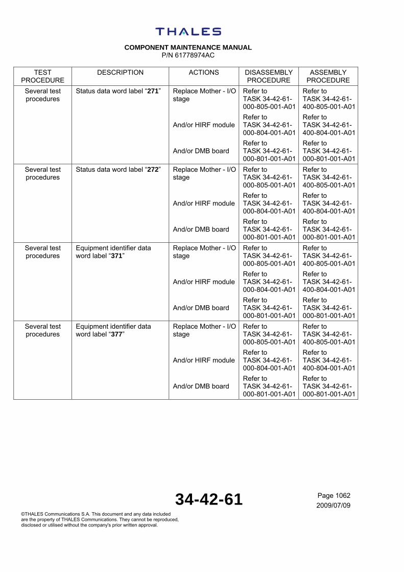
COMPONENT MAINTENANCE MANUAL
P/N 61778974AC
34-42-61 Page 1062
2009/07/09©THALES Communications S.A. This document and any data included are the property of THALES Communications. They cannot be reproduced, disclosed or utilised without the company's prior written approval.
TEST PROCEDURE
DESCRIPTION ACTIONS DISASSEMBLY PROCEDURE
ASSEMBLY PROCEDURE
Several test procedures
Status data word label “271” Replace Mother - I/O stage
And/or HIRF module
And/or DMB board
Refer to TASK 34-42-61-000-805-001-A01
Refer to TASK 34-42-61-000-804-001-A01
Refer to TASK 34-42-61-000-801-001-A01
Refer to TASK 34-42-61-400-805-001-A01
Refer to TASK 34-42-61-400-804-001-A01
Refer to TASK 34-42-61-000-801-001-A01
Several test procedures
Status data word label “272” Replace Mother - I/O stage
And/or HIRF module
And/or DMB board
Refer to TASK 34-42-61-000-805-001-A01
Refer to TASK 34-42-61-000-804-001-A01
Refer to TASK 34-42-61-000-801-001-A01
Refer to TASK 34-42-61-400-805-001-A01
Refer to TASK 34-42-61-400-804-001-A01
Refer to TASK 34-42-61-000-801-001-A01
Several test procedures
Equipment identifier data word label “371”
Replace Mother - I/O stage
And/or HIRF module
And/or DMB board
Refer to TASK 34-42-61-000-805-001-A01
Refer to TASK 34-42-61-000-804-001-A01
Refer to TASK 34-42-61-000-801-001-A01
Refer to TASK 34-42-61-400-805-001-A01
Refer to TASK 34-42-61-400-804-001-A01
Refer to TASK 34-42-61-000-801-001-A01
Several test procedures
Equipment identifier data word label “377”
Replace Mother - I/O stage
And/or HIRF module
And/or DMB board
Refer to TASK 34-42-61-000-805-001-A01
Refer to TASK 34-42-61-000-804-001-A01
Refer to TASK 34-42-61-000-801-001-A01
Refer to TASK 34-42-61-400-805-001-A01
Refer to TASK 34-42-61-400-804-001-A01
Refer to TASK 34-42-61-000-801-001-A01

COMPONENT MAINTENANCE MANUAL
P/N 61778974AC
34-42-61 Page 1063
2009/07/09©THALES Communications S.A. This document and any data included are the property of THALES Communications. They cannot be reproduced, disclosed or utilised without the company's prior written approval.
TEST PROCEDURE
DESCRIPTION ACTIONS DISASSEMBLY PROCEDURE
ASSEMBLY PROCEDURE
(14) Refer to SUBTASK 34-42-
61-700-014-01
Simulation of TX antenna failure
Replace HIRF module
And/or Mother - I/O stage
And/or DMB board
Refer to TASK 34-42-61-000-804-001-A01
Refer to TASK 34-42-61-000-805-001-A01
Refer to TASK 34-42-61-000-801-001-A01
Refer to TASK 34-42-61-400-804-001-A01
Refer to TASK 34-42-61-400-805-001-A01
Refer to TASK 34-42-61-000-801-001-A01
(15) Refer to SUBTASK 34-42-
61-700-015-01
Built In Test function Replace HIRF module
And/or Mother - I/O stage
And/or DMB board
Refer to TASK 34-42-61-000-804-001-A01
Refer to TASK 34-42-61-000-805-001-A01
Refer to TASK 34-42-61-000-801-001-A01
Refer to TASK 34-42-61-400-804-001-A01
Refer to TASK 34-42-61-400-805-001-A01
Refer to TASK 34-42-61-000-801-001-A01
(16) Refer to SUBTASK 34-42-
61-700-016-01
Sensitivity Replace Radio module
And/or DMB board
Refer to TASK 34-42-61-000-803-001-A01
Refer to TASK 34-42-61-000-801-001-A01
Refer to TASK 34-42-61-400-803-001-A01
Refer to TASK 34-42-61-400-801-001-A01
(17) Refer to SUBTASK 34-42-
61-700-017-01
Height accuracy Replace Radio module
And/or DMB board
Refer to TASK 34-42-61-000-803-001-A01
Refer to TASK 34-42-61-000-801-001-A01
Refer to TASK 34-42-61-400-803-001-A01
Refer to TASK 34-42-61-400-801-001-A01
(18) Refer to SUBTASK 34-42-
61-700-018-01
Response time performance during a height step
Replace Radio module
And/or DMB board
Refer to TASK 34-42-61-000-803-001-A01
Refer to TASK 34-42-61-000-801-001-A01
Refer to TASK 34-42-61-400-803-001-A01
Refer to TASK 34-42-61-400-801-001-A01
(19) Refer to SUBTASK 34-42-
61-700-019-01
Operation at +22V and +18V Replace Power Supply stage
Refer to TASK 34-42-61-000-802-001-A01
Refer to TASK 34-42-61-400-802-001-A01
(20) Refer to SUBTASK 34-42-
61-700-020-01
Operation at +30.3V Replace Power Supply stage
Refer to TASK 34-42-61-000-802-001-A01
Refer to TASK 34-42-61-400-802-001-A01

COMPONENT MAINTENANCE MANUAL
P/N 61778974AC
34-42-61 Page 1064
2009/07/09©THALES Communications S.A. This document and any data included are the property of THALES Communications. They cannot be reproduced, disclosed or utilised without the company's prior written approval.
THIS PAGE INTENTIONALLY LEFT BLANK
COMPONENT MAINTENANCE MANUAL
P/N 61778974AC
34-42-61 Page 3001
2009/07/09©THALES Communications S.A. This document and any data included are the property of THALES Communications. They cannot be reproduced, disclosed or utilised without the company's prior written approval.
DISASSEMBLY
TASK 34-42-61-871-804-A01
1. GENERAL
Disassemble the AHV1600 unit only when repair is necessary.
Run the performance test given in the Testing chapter of this manual, and the Fault Isolation test given in the Fault Isolation section to determine if and what disassembly is required.
This section deals with the procedures for the removal and disassembly of the subassemblies of the AHV1600 unit.
A. PRECAUTIONS
WARNING: REMOVE ALL POWER CABLES BEFORE DISASSEMBLING ANY PORTION OF THE EQUIPMENT. DISASSEMBLING THE EQUIPMENT WITH THE POWER CABLES CONNECTED IS DANGEROUS TO LIFE AND ALSO MAY CAUSE VOLTAGE TRANSIENTS THAT CAN DAMAGE THE EQUIPMENT.
WARNING: REFER TO THE COMPONENT SEALED MATERIALS WARNING ON THE ADVISORIES PAGE IN THE INTRODUCTION SECTION.
CAUTION: SOLDERING EQUIPMENT MUST BE WELL GROUNDED. WHEN SOLDERING AND UNSOLDERING A SOLID-STATE DEVICE, USE A HEAT SINK ON THE LEADS TO PREVENT DAMAGE TO THE DEVICE.
CAUTION: REFER TO ESDS HANDLING CAUTION IN THE INTRODUCTION SECTION OF TESTING AND FAULT ISOLATION OF THIS MANUAL.
B. PROCEDURES OF DISASSEMBLY
The instructions for disassembly are given step by step, in a logical order, referring to the Figure numbers and item numbers (in parentheses) of the corresponding illustrations in the Illustrated Parts List.
(1) GENERAL PRECAUTIONS TO BE OBSERVED
Job is to be performed in a clean room. Disassembly and cleaning of the equipment must be carried out with the recommended tools and products only. The parts must be protected as soon as they are disassembled. Most screws and nuts on the AHV1600 unit are secured with locking compound (example, LOCTITE SR 222). This varnish may be diluted, if required, with acetone or lacquer thinner.

COMPONENT MAINTENANCE MANUAL
P/N 61778974AC
34-42-61 Page 3002
2009/07/09©THALES Communications S.A. This document and any data included are the property of THALES Communications. They cannot be reproduced, disclosed or utilised without the company's prior written approval.
(2) NECESSARY TOOLS
Refer to the I.P.L. part of this manual to know the different sort of screws used to maintain in position the boards; to unscrews the screws, use the dedicated screwdriver.
(3) LIST OF DISASSEMBLIES
Hereafter are listed the sub-assemblies which can be dismantled for NTI2 (level of maintenance 2)
- DMB board,
- Power Supply stage,
- Radio module,
- HIRF module,
- Mother - I/O stage,
- Chassis.
TASK 34-42-61-000-801-A01
2. DISASSEMBLY OF DMB BOARD
A. REASON FOR THE JOB
Self-explanatory.
B. JOB SET-UP INFORMATION
(1) TOOLS, FIXTURES AND TEST EQUIPMENT
The table that follows gives the tools necessary to disassemble the AHV1600 Transceiver
NOTE: You can use equivalent tools as an alternative to those given in the table.
NOTE: Refer to SPECIAL TOOLS, FIXTURES AND EQUIPMENT AND CONSUMABLES for more data.
TABLE 34-42-61-993-301-A01
REFERENCE QTY NAME
No specific 1 Screwdriver
C. JOB SET-UP
Not applicable.

COMPONENT MAINTENANCE MANUAL
P/N 61778974AC
34-42-61 Page 3003
2009/07/09©THALES Communications S.A. This document and any data included are the property of THALES Communications. They cannot be reproduced, disclosed or utilised without the company's prior written approval.
D. PROCEDURE
SUBTASK 34-42-61-020-001-A01
(1) DISASSEMBLY OF DMB BOARD (Figure 1, item 120)
(a) Unscrew the 6 screws (Figure 1, item 100) and remove the left cover (Figure 1, item 90).
(b) Remove carefully the DMB board (Figure 1, item 120) with the dedicated cord.
TASK 34-42-61-000-802-A01
3. DISASSEMBLY OF POWER SUPPLY STAGE
A. REASON FOR THE JOB
Self-explanatory.
B. JOB SET-UP INFORMATION
(1) TOOLS, FIXTURES AND TEST EQUIPMENT
The table that follows gives the tools necessary to disassemble the AHV1600 Transceiver
NOTE: You can use equivalent tools as an alternative to those given in the table.
NOTE: Refer to SPECIAL TOOLS, FIXTURES AND EQUIPMENT AND CONSUMABLES for more data.
TABLE 34-42-61-993-302-A01
REFERENCE QTY NAME
6100188A 1 Power Supply stage removal tool
No specific 1 Screwdriver
C. JOB SET-UP
Not applicable.
D. PROCEDURE
SUBTASK 34-42-61-020-002-A01
(1) DISASSEMBLY OF POWER SUPPLY STAGE (Figure 1, item 110)
(a) Unscrew the 6 screws (Figure 1, item 100) and remove the left cover (Figure 1, item 90).

COMPONENT MAINTENANCE MANUAL
P/N 61778974AC
34-42-61 Page 3004
2009/07/09©THALES Communications S.A. This document and any data included are the property of THALES Communications. They cannot be reproduced, disclosed or utilised without the company's prior written approval.
(b) Remove carefully the Power Supply stage (Figure 1, item 110) with the Power Supply stage removal tool (P/N 6100188A).
TASK 34-42-61-000-803-A01
4. DISASSEMBLY OF RADIO MODULE
A. REASON FOR THE JOB
Self-explanatory.
B. JOB SET-UP INFORMATION
(1) TOOLS, FIXTURES AND TEST EQUIPMENT
The table that follows gives the tools necessary to disassemble the AHV1600 Transceiver
NOTE: You can use equivalent tools as an alternative to those given in the table.
NOTE: Refer to SPECIAL TOOLS, FIXTURES AND EQUIPMENT AND CONSUMABLES for more data.
TABLE 34-42-61-993-303-A01
REFERENCE QTY NAME
No specific 1 Screwdriver
(2) REFERENCE INFORMATION
TABLE 34-42-61-996-304-A01
REFERENCE DESIGNATION
TASK 34-42-61-000-801-A01 Disassembly of DMB board
TASK 34-42-61-000-802-A01 Disassembly of Power Supply stage
C. JOB SET-UP
Not applicable.
D. PROCEDURE
SUBTASK 34-42-61-020-003-A01
(1) DISASSEMBLY OF RADIO MODULE (Figure 1, item 40)

COMPONENT MAINTENANCE MANUAL
P/N 61778974AC
34-42-61 Page 3005
2009/07/09©THALES Communications S.A. This document and any data included are the property of THALES Communications. They cannot be reproduced, disclosed or utilised without the company's prior written approval.
CAUTION: BE CAREFUL TO THE COAXIAL CONNECTORS (Figure 1, item 210).
(a) Unscrew “TX” and “RX” connectors (Figure 1, item 200) from the front side of the AHV1600 unit.
(b) Unscrew the 10 screws (Figure 1, item 20) and remove the upper cover (Figure 1, item 10).
(c) Remove the foil (Figure 1, item 30).
(d) Remove the DMB board (refer to TASK 34-42-61-000-801-A01).
(e) Remove the Power Supply stage (refer to TASK 34-42-61-000-802-A01).
(f) Remove carefully the Radio module (Figure 1, item 40).
TASK 34-42-61-000-804-A01
5. DISASSEMBLY OF HIRF MODULE
A. REASON FOR THE JOB
Self-explanatory.
B. JOB SET-UP INFORMATION
(1) TOOLS, FIXTURES AND TEST EQUIPMENT
The table that follows gives the tools necessary to disassemble the AHV1600 Transceiver
NOTE: You can use equivalent tools as an alternative to those given in the table.
NOTE: Refer to SPECIAL TOOLS, FIXTURES AND EQUIPMENT AND CONSUMABLES for more data.
TABLE 34-42-61-993-305-A01
REFERENCE QTY NAME
No specific 1 Screwdriver
C. JOB SET-UP
Not applicable.
D. PROCEDURE
SUBTASK 34-42-61-020-004-A01
(1) DISASSEMBLY OF HIRF MODULE (Figure 1, item 160)

COMPONENT MAINTENANCE MANUAL
P/N 61778974AC
34-42-61 Page 3006
2009/07/09©THALES Communications S.A. This document and any data included are the property of THALES Communications. They cannot be reproduced, disclosed or utilised without the company's prior written approval.
(a) Unscrew the 4 screws and washers (Figure 1, items 170 and 180) on the front face of the AHV1600 unit.
(b) Take out slightly the front face (Figure 1, item 160) of the AHV unit.
(c) Unscrew carefully the 4 screws and washers (Figure 1, items 170 and 180) which maintain in position the second part of the HIRF module (Figure 1, item 160) in the chassis (Figure 1, item 190).
(d) Remove carefully the HIRF module (Figure 1, item 160).
TASK 34-42-61-000-805-A01
6. DISASSEMBLY OF MOTHER - I/O STAGE
A. REASON FOR THE JOB
Self-explanatory.
B. JOB SET-UP INFORMATION
(1) TOOLS, FIXTURES AND TEST EQUIPMENT
The table that follows gives the tools necessary to disassemble the AHV1600 Transceiver
NOTE: You can use equivalent tools as an alternative to those given in the table.
NOTE: Refer to SPECIAL TOOLS, FIXTURES AND EQUIPMENT AND CONSUMABLES for more data.
TABLE 34-42-61-993-306-A01
REFERENCE QTY NAME
No specific 1 Screwdriver
(2) REFERENCE INFORMATION
TABLE 34-42-61-996-307-A01
REFERENCE DESIGNATION
TASK 34-42-61-000-803-A01 Disassembly of Radio module
TASK 34-42-61-000-804-A01 Disassembly of HIRF module
COMPONENT MAINTENANCE MANUAL
P/N 61778974AC
34-42-61 Page 3007
2009/07/09©THALES Communications S.A. This document and any data included are the property of THALES Communications. They cannot be reproduced, disclosed or utilised without the company's prior written approval.
C. JOB SET-UP
Not applicable.
D. PROCEDURE
SUBTASK 34-42-61-020-005-A01
(1) DISASSEMBLY OF MOTHER - I/O STAGE (Figure 1, item 130)
(a) Remove the Radio module (refer to TASK 34-42-61-000-803-A01).
(b) Remove the HIRF module (refer to TASK 34-42-61-000-804-A01).
(c) Unscrew the 5 screws and washers (Figure 1, items 140 and 150) which maintain the Mother - I/O stage (Figure 1, item 130) in position.
(d) Remove carefully the Mother - I/O stage (Figure 1, item 130).
TASK 34-42-61-000-806-A01
7. DISASSEMBLY OF CHASSIS
A. REASON FOR THE JOB
Self-explanatory.
B. JOB SET-UP INFORMATION
(1) TOOLS, FIXTURES AND TEST EQUIPMENT
The table that follows gives the tools necessary to disassemble the AHV1600 Transceiver
NOTE: You can use equivalent tools as an alternative to those given in the table.
NOTE: Refer to SPECIAL TOOLS, FIXTURES AND EQUIPMENT AND CONSUMABLES for more data.

COMPONENT MAINTENANCE MANUAL
P/N 61778974AC
34-42-61 Page 3008
2009/07/09©THALES Communications S.A. This document and any data included are the property of THALES Communications. They cannot be reproduced, disclosed or utilised without the company's prior written approval.
TABLE 34-42-61-993-308-A01
REFERENCE QTY NAME
No specific 1 Screwdriver
(2) REFERENCE INFORMATION
TABLE 34-42-61-996-309-A01
REFERENCE DESIGNATION
TASK 34-42-61-000-805-A01 Disassembly of Mother - I/O stage
C. JOB SET-UP
Not applicable.
D. PROCEDURE
SUBTASK 34-42-61-020-006-A01
(1) DISASSEMBLY OF CHASSIS (Figure 1, item 190)
(a) Remove the Mother - I/O stage (refer to TASK 34-42-61-000-805-A01).

COMPONENT MAINTENANCE MANUAL
P/N 61778974AC
34-42-61 Page 4001
2009/07/09©THALES Communications S.A. This document and any data included are the property of THALES Communications. They cannot be reproduced, disclosed or utilised without the company's prior written approval.
CLEANING
TASK 34-42-61-100-801-A01
1. CLEANING OF AHV1600 TRANSCEIVER
A. REASON FOR THE JOB
Self-explanatory.
B. JOB SET−UP INFORMATION
(1) TOOLS, FIXTURES AND TEST EQUIPMENT
Not applicable.
(2) CONSUMABLES
The table that follows gives the consumables necessary to do the cleaning of the AHV1600 Transceiver.
NOTE: You can use equivalent products as an alternative to those given in the table.
NOTE: Refer to SPECIAL TOOLS, FIXTURES, EQUIPMENT AND CONSUMABLES for more data.
TABLE 34-42-61-994-401-A01
ITEM REFERENCE QTY NAME
Item 1 Commercially available - White spirit
C. JOB SET−UP
Not applicable.
D. PROCEDURE
SUBTASK 34-42-61-160-001-A01
(1) ATTACHING PARTS
(a) Clean all attaching parts in a bath of cleaning compound (item1). Then full dry with compressed air.

COMPONENT MAINTENANCE MANUAL
P/N 61778974AC
34-42-61 Page 4002
2009/07/09©THALES Communications S.A. This document and any data included are the property of THALES Communications. They cannot be reproduced, disclosed or utilised without the company's prior written approval.
SUBTASK 34-42-61-160-002-A01
(2) AHV1600 Transceiver
(a) Clean the AHV1600 Transceiver with a cloth soaked in water.
COMPONENT MAINTENANCE MANUAL
P/N 61778974AC
34-42-61 Page 5001
2009/07/09©THALES Communications S.A. This document and any data included are the property of THALES Communications. They cannot be reproduced, disclosed or utilised without the company's prior written approval.
INSPECTION / CHECK
TASK 34-42-61-200-801-A01
1. INSPECTION / CHECK OF AHV1600 TRANSCEIVER
A. REASON FOR THE JOB
Self-explanatory.
B. JOB SET−UP INFORMATION
Not applicable.
C. JOB SET−UP
Not applicable.
D. PROCEDURE
SUBTASK 34-42-61-210-001-A01
(1) ATTACHING PARTS
(a) Visually examine the screw heads and the threads. Reject all defective attaching parts.
(b) Systematically reject the lock washers.
SUBTASK 34-42-61-210-002-A01
(2) MECHANICAL PARTS
(a) Examine the surface condition of the mechanical parts.
(b) Make sure that the mechanical parts are not damaged.
(c) Reject all defective parts.
SUBTASK 34-42-61-210-003-A01
(3) ELECTRICAL COMPONENTS
(a) Examine the condition of the wiring and solders, specially on the connectors, printed circuits, pushbuttons and switch assemblies.
(b) Examine the condition of the insulators of the electrical component and printed circuits.
(c) Reject systematically all defective parts.


COMPONENT MAINTENANCE MANUAL
P/N 61778974AC
34-42-61 Page 5001
2009/07/09©THALES Communications S.A. This document and any data included are the property of THALES Communications. They cannot be reproduced, disclosed or utilised without the company's prior written approval.
THIS PAGE INTENTIONALLY LEFT BLANK


COMPONENT MAINTENANCE MANUAL
P/N 61778974AC
34-42-61 Page 6001
2009/07/09©THALES Communications S.A. This document and any data included are the property of THALES Communications. They cannot be reproduced, disclosed or utilised without the company's prior written approval.
REPAIR
TASK 34-42-61-300-801-A01
1. REPAIR OF AHV1600 TRANSCEIVER
A. REASON FOR THE JOB
Self-explanatory.
B. JOB SET−UP INFORMATION
Not applicable.
C. JOB SET-UP
(1) GENERAL
NOTE: Refer to the "DESCRIPTION AND OPERATION" Figures for the Electrical Diagram, and the I.P.L Figures for the components location-layout.
The SMD can be replaced when the boards have to be repaired and when operators are used to this delicate and fine type of work. When operators can not do so, it is suggested to return such a repair to the Original Equipment Manufacturer.
D. PROCEDURE
SUBTASK 34-42-61-310-001-A01
(1) SURFACE MOUNT DEVICE
CAUTION: BEFORE TO START TO WORK ON THE PRINTED CIRCUIT BOARD, IT IS NECESSARY TO DO THE TEST GIVEN IN THE "TESTING AND FAULT ISOLATION" SECTION TO FIND AND ISOLATE POSSIBLE DEFECTS.
For unsoldering and soldering SMD:
(a) Use the special tools locally available and specifically dedicated to SMR (Surface Mounting Repair).
(b) Avoid burning the printed board.
(c) Avoid detaching the tracks on the board.
(d) Avoid re-use of SMD which have been unsoldered.
(e) Avoid overheating SMD and adjacent components.
(f) Avoid changing a same SMD on the same board more than three times, in order to maintain the good quality of the whole board.

COMPONENT MAINTENANCE MANUAL
P/N 61778974AC
34-42-61 Page 6002
2009/07/09©THALES Communications S.A. This document and any data included are the property of THALES Communications. They cannot be reproduced, disclosed or utilised without the company's prior written approval.
COMPONENT MAINTENANCE MANUAL
P/N 61778974AC
34-42-61 Page 7001
2009/07/09©THALES Communications S.A. This document and any data included are the property of THALES Communications. They cannot be reproduced, disclosed or utilised without the company's prior written approval.
ASSEMBLY
TASK 34-42-61-871-805-A01
1. GENERAL
This section provides information for the assembly of the AHV1600 unit.
The order of assembly starts with the lowest sub-assembly to the complete module.
Reassembly is to be performed in a clean, dust-free room.
All screws shall be secured by a drop of varnish.
A. PRECAUTIONS
CAUTION: REFER TO ESDS HANDLING CAUTION IN THE INTRODUCTION SECTION OF TESTING AND FAULT ISOLATION OF THIS MANUAL.
CAUTION: WHEN REPLACING A SOLID-STATE COMPONENT, USE A HEAT SINK ATTACHED TO THE LEADS TO PREVENT DAMAGE TO THE DEVICE. THE SOLDERING IRON SHOULD BE GROUNDED PROPERLY WITH RESPECT TO BOARD OR CHASSIS WHEN REPLACING LOW-VOLTAGE DEVICES (DIODES,TRANSISTORS, INTEGRATED CIRCUITS, ETC).
B. PROCEDURES OF DISASSEMBLY
The reassembly instructions are given step by step in a logical order, referring of the Figure and item numbers of the corresponding illustrations in the Illustrated Parts List.
(1) NECESSARY TOOLS
Refer to the I.P.L. part of this manual to know the different sort of screws used to maintain in position the boards to be in accordance with the different tools listed in SPECIAL TOOLS, FIXTURES AND EQUIPMENT AND CONSUMABLES.
(2) LIST OF RE-ASSEMBLIES
Hereafter are listed the sub-assemblies which can be re-assembled for NTI2 (level of maintenance 2)
- DMB board,
- Power Supply stage,
- Radio module,
- HIRF module,

COMPONENT MAINTENANCE MANUAL
P/N 61778974AC
34-42-61 Page 7002
2009/07/09©THALES Communications S.A. This document and any data included are the property of THALES Communications. They cannot be reproduced, disclosed or utilised without the company's prior written approval.
- Mother - I/O stage,
- Chassis.
TASK 34-42-61-400-801-A01
2. ASSEMBLY OF DMB BOARD
A. REASON FOR THE JOB
Self-explanatory.
B. JOB SET-UP INFORMATION
(1) TOOLS, FIXTURES AND TEST EQUIPMENT
The table that follows gives the tools necessary to disassemble the AHV1600 Transceiver
NOTE: You can use equivalent tools as an alternative to those given in the table.
NOTE: Refer to SPECIAL TOOLS, FIXTURES AND EQUIPMENT AND CONSUMABLES for more data.
TABLE 34-42-61-993-701-A01
REFERENCE QTY NAME
No specific 1 Screwdriver
(2) CONSUMABLES
The table that follows gives the consumables necessary to disassemble the AHV1600 Transceiver
NOTE: You can use equivalent consumables as an alternative to those given in the table.
NOTE: Refer to SPECIAL TOOLS, FIXTURES AND EQUIPMENT AND CONSUMABLES for more data.
TABLE 34-42-61-994-702-A01
REFERENCE NAME
Loctite SR222 Thread locking compound
(3) REFERENCE INFORMATION
COMPONENT MAINTENANCE MANUAL
P/N 61778974AC
34-42-61 Page 7003
2009/07/09©THALES Communications S.A. This document and any data included are the property of THALES Communications. They cannot be reproduced, disclosed or utilised without the company's prior written approval.
C. JOB SET-UP
Not applicable.
D. PROCEDURE
SUBTASK 34-42-61-420-001-A01
(1) ASSEMBLY OF DMB BOARD (Figure 1, item 120)
NOTE: after the replacement of the DMB board, it may be necessary to run the software downloading procedure (refer to TESTING AND FAULT ISOLATION).
(a) Insert carefully the DMB board (Figure 1, item 120) in its dedicated housing in the chassis (Figure 1, item 190).
(b) Plug carefully the DMB board connector in the connector of the Mother - I/O stage (Figure 1, item 130).
(c) Replace the gasket (Figure 1, item 105) by a new one.
(d) Install carefully the left cover (Figure 1, item 90) on the chassis (Figure 1, item 190).
(e) Put locking compound (Loctite SR222) on the thread of the screws (Figure 1, item 100).
(f) Screw the 6 screws (Figure 1, item 100) with a torque of 0.8 N.m (0.59 lbf.in).
TASK 34-42-61-400-802-A01
3. ASSEMBLY OF POWER SUPPLY STAGE
A. REASON FOR THE JOB
Self-explanatory.
B. JOB SET-UP INFORMATION
(1) TOOLS, FIXTURES AND TEST EQUIPMENT
The table that follows gives the tools necessary to disassemble the AHV1600 Transceiver
NOTE: You can use equivalent tools as an alternative to those given in the table.
NOTE: Refer to SPECIAL TOOLS, FIXTURES AND EQUIPMENT AND CONSUMABLES for more data.
COMPONENT MAINTENANCE MANUAL
P/N 61778974AC
34-42-61 Page 7004
2009/07/09©THALES Communications S.A. This document and any data included are the property of THALES Communications. They cannot be reproduced, disclosed or utilised without the company's prior written approval.
TABLE 34-42-61-993-703-A01
REFERENCE QTY NAME
No specific 1 Screwdriver
(2) CONSUMABLES
The table that follows gives the consumables necessary to disassemble the AHV1600 Transceiver
NOTE: You can use equivalent consumables as an alternative to those given in the table.
NOTE: Refer to SPECIAL TOOLS, FIXTURES AND EQUIPMENT AND CONSUMABLES for more data.
TABLE 34-42-61-994-704-A01
REFERENCE NAME
Loctite SR222 Thread locking compound
(3) REFERENCE INFORMATION
C. JOB SET-UP
Not applicable.
D. PROCEDURE
SUBTASK 34-42-61-420-002-A01
(1) ASSEMBLY OF POWER SUPPLY STAGE (Figure 1, item 110)
(a) Insert carefully the Power Supply stage (Figure 1, item 110) in its dedicated housing in the chassis (Figure 1, item 190).
(b) Plug carefully the Power Supply stage connector in the connector of the Mother - I/O stage (Figure 1, item 130).
(c) Replace the gasket (Figure 1, item 105) by a new one.
(d) Install carefully the left cover (Figure 1, item 90) on the chassis (Figure 1, item 190).
(e) Put locking compound (Loctite SR222) on the thread of the screws (Figure 1, item 100).
(f) Screw the 6 screws (Figure 1, item 100) with a torque of 0.8 N.m (0.59 lbf.in).
TASK 34-42-61-400-803-A01
COMPONENT MAINTENANCE MANUAL
P/N 61778974AC
34-42-61 Page 7005
2009/07/09©THALES Communications S.A. This document and any data included are the property of THALES Communications. They cannot be reproduced, disclosed or utilised without the company's prior written approval.
4. ASSEMBLY OF RADIO MODULE
A. REASON FOR THE JOB
Self-explanatory.
B. JOB SET-UP INFORMATION
(1) TOOLS, FIXTURES AND TEST EQUIPMENT
The table that follows gives the tools necessary to disassemble the AHV1600 Transceiver
NOTE: You can use equivalent tools as an alternative to those given in the table.
NOTE: Refer to SPECIAL TOOLS, FIXTURES AND EQUIPMENT AND CONSUMABLES for more data.
TABLE 34-42-61-993-705-A01
REFERENCE QTY NAME
No specific 1 Screwdriver
(2) CONSUMABLES
The table that follows gives the consumables necessary to disassemble the AHV1600 Transceiver
NOTE: You can use equivalent consumables as an alternative to those given in the table.
NOTE: Refer to SPECIAL TOOLS, FIXTURES AND EQUIPMENT AND CONSUMABLES for more data.
TABLE 34-42-61-994-706-A01
REFERENCE NAME
Loctite SR222 Thread locking compound
(3) REFERENCE INFORMATION
TABLE 34-42-61-996-707-A01
REFERENCE DESIGNATION
TASK 34-42-61-400-801-A01 Assembly of DMB board

COMPONENT MAINTENANCE MANUAL
P/N 61778974AC
34-42-61 Page 7006
2009/07/09©THALES Communications S.A. This document and any data included are the property of THALES Communications. They cannot be reproduced, disclosed or utilised without the company's prior written approval.
REFERENCE DESIGNATION
TASK 34-42-61-400-802-A01 Assembly of Power Supply stage
C. JOB SET-UP
Not applicable.
D. PROCEDURE
SUBTASK 34-42-61-420-003-A01
(1) ASSEMBLY OF RADIO MODULE (Figure 1, item 40)
NOTE: after the replacement of the Radio module, it may be necessary to run the software downloading procedure (refer to Testing and Fault isolation part).
(a) Check that the foil (Figure 1, item 70) is in position.
(b) Install carefully the Radio module (Figure 1, item 40) in its dedicated housing in the chassis (Figure 1, item 190).
(c) Plug carefully the Radio module connector in the connector of the Mother - I/O stage (Figure 1, item 130).
(d) Install carefully the foil (Figure 1, item 30) on the Radio module (Figure 1, item 40).
(e) Replace the gasket (Figure 1, item 25) by a new one.
(f) Install carefully the upper cover (Figure 1, item 10).
(g) Put locking compound (Loctite SR222) on the thread of the 10 screws (Figure 1, item 20).
(h) Screw the 10 screws (Figure 1, item 20) with a torque of 0.8 N.m (0.59 lbf.in).
(i) Put the coaxial connectors (Figure 1, item 210) in position.
(j) Screw the “TX” and “RX” connectors (Figure 1, item 200) in their dedicated housing with a torque of 4 N.m (2.95 lbf.in).
(k) Install the DMB board (refer to TASK 34-42-61-400-801-A01).
(l) Install the Power Supply stage (refer to TASK 34-42-61-400-802-A01).
TASK 34-42-61-400-804-A01
5. ASSEMBLY OF HIRF MODULE
A. REASON FOR THE JOB
Self-explanatory.
COMPONENT MAINTENANCE MANUAL
P/N 61778974AC
34-42-61 Page 7007
2009/07/09©THALES Communications S.A. This document and any data included are the property of THALES Communications. They cannot be reproduced, disclosed or utilised without the company's prior written approval.
B. JOB SET-UP INFORMATION
(1) TOOLS, FIXTURES AND TEST EQUIPMENT
The table that follows gives the tools necessary to disassemble the AHV1600 Transceiver
NOTE: You can use equivalent tools as an alternative to those given in the table.
NOTE: Refer to SPECIAL TOOLS, FIXTURES AND EQUIPMENT AND CONSUMABLES for more data.
TABLE 34-42-61-993-708-A01
REFERENCE QTY NAME
No specific 1 Screwdriver
(2) CONSUMABLES
The table that follows gives the consumables necessary to disassemble the AHV1600 Transceiver
NOTE: You can use equivalent consumables as an alternative to those given in the table.
NOTE: Refer to SPECIAL TOOLS, FIXTURES AND EQUIPMENT AND CONSUMABLES for more data.
TABLE 34-42-61-994-709-A01
REFERENCE NAME
Loctite SR222 Thread locking compound
C. JOB SET-UP
Not applicable.
D. PROCEDURE
SUBTASK 34-42-61-420-004-A01
(1) ASSEMBLY OF HIRF MODULE (Figure 1, item 160)
(a) Replace the gasket (Figure 1, item 185) by a new one.
(b) Install carefully the rear part of the HIRF module (Figure 1, item 160) in its dedicated housing in the chassis (Figure 1, item 190).
(c) Put locking compound (Loctite SR222) on the thread of the 4 screws (Figure 1, item 170).

COMPONENT MAINTENANCE MANUAL
P/N 61778974AC
34-42-61 Page 7008
2009/07/09©THALES Communications S.A. This document and any data included are the property of THALES Communications. They cannot be reproduced, disclosed or utilised without the company's prior written approval.
(d) Screw the 4 screws and washers (Figure 1, item 170) with a torque of 0.8 N.m (0.59 lbf.in).
(e) Install carefully the front face of the HIRF module (Figure 1, item 160) on the chassis (Figure 1, item 190).
(f) Put locking compound (Loctite SR222) on the thread of the 4 screws (Figure 1, item 170).
(g) Attach the front part of the HIRF module (160) to the chassis (190) with the 4 screws (170) and the 4 washers (180).
(h) Screw the 4 screws and washers (Figure 1, items 170 and 180) with a torque of 0.8 N.m (0.59 lbf.in).

COMPONENT MAINTENANCE MANUAL
P/N 61778974AC
34-42-61 Page 7009
2009/07/09©THALES Communications S.A. This document and any data included are the property of THALES Communications. They cannot be reproduced, disclosed or utilised without the company's prior written approval.
TASK 34-42-61-400-805-A01
6. ASSEMBLY OF MOTHER - I/O STAGE
A. REASON FOR THE JOB
Self-explanatory.
B. JOB SET-UP INFORMATION
(1) TOOLS, FIXTURES AND TEST EQUIPMENT
The table that follows gives the tools necessary to disassemble the AHV1600 Transceiver
NOTE: You can use equivalent tools as an alternative to those given in the table.
NOTE: Refer to SPECIAL TOOLS, FIXTURES AND EQUIPMENT AND CONSUMABLES for more data.
TABLE 34-42-61-993-710-A01
REFERENCE QTY NAME
No specific 1 Screwdriver
(2) CONSUMABLES
The table that follows gives the consumables necessary to disassemble the AHV1600 Transceiver
NOTE: You can use equivalent consumables as an alternative to those given in the table.
NOTE: Refer to SPECIAL TOOLS, FIXTURES AND EQUIPMENT AND CONSUMABLES for more data.
TABLE 34-42-61-994-711-A01
REFERENCE NAME
Loctite SR222 Thread locking compound
(3) REFERENCE INFORMATION

COMPONENT MAINTENANCE MANUAL
P/N 61778974AC
34-42-61 Page 7010
2009/07/09©THALES Communications S.A. This document and any data included are the property of THALES Communications. They cannot be reproduced, disclosed or utilised without the company's prior written approval.
TABLE 34-42-61-996-712-A01
REFERENCE DESIGNATION
TASK 34-42-61-400-803-A01 Assembly of Radio module
TASK 34-42-61-400-804-A01 Assembly of HIRF module
C. JOB SET-UP
Not applicable.
D. PROCEDURE
SUBTASK 34-42-61-420-005-A01
(1) ASSEMBLY OF MOTHER - I/O STAGE (Figure 1, item 130)
NOTE: after the replacement of the Mother - I/O stage, it may be necessary to run the software downloading procedure (refer to TESTING AND FAULT ISOLATION).
(a) Install carefully the Mother - I/O stage (Figure 1, item 130) in its dedicated housing in the chassis (Figure 1, item 190).
(b) Put locking compound (Loctite SR222) on the thread of the 5 screws (Figure 1, item 140).
(c) Screw the 5 screws and washers (Figure 1, items 140 and 150) with a torque of 0.8 N.m (0.59 lbf.in).
(d) Install the Radio module (refer to TASK 34-42-61-400-803-A01).
(e) Install the HIRF module (refer to TASK 34-42-61-400-804-A01).
TASK 34-42-61-400-806-A01
7. ASSEMBLY OF CHASSIS
A. REASON FOR THE JOB
Self-explanatory.
B. JOB SET-UP INFORMATION
(1) TOOLS, FIXTURES AND TEST EQUIPMENT
The table that follows gives the tools necessary to disassemble the AHV1600 Transceiver
NOTE: You can use equivalent tools as an alternative to those given in the table.
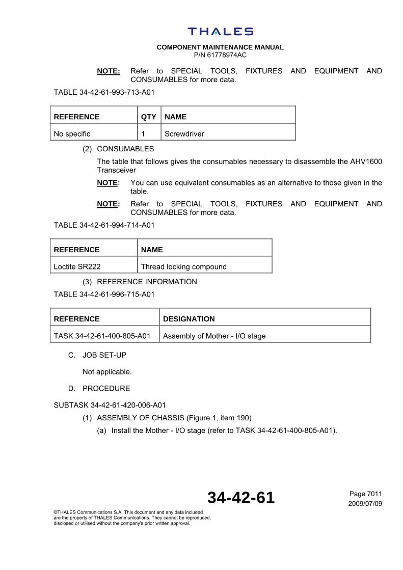
COMPONENT MAINTENANCE MANUAL
P/N 61778974AC
34-42-61 Page 7011
2009/07/09©THALES Communications S.A. This document and any data included are the property of THALES Communications. They cannot be reproduced, disclosed or utilised without the company's prior written approval.
NOTE: Refer to SPECIAL TOOLS, FIXTURES AND EQUIPMENT AND CONSUMABLES for more data.
TABLE 34-42-61-993-713-A01
REFERENCE QTY NAME
No specific 1 Screwdriver
(2) CONSUMABLES
The table that follows gives the consumables necessary to disassemble the AHV1600 Transceiver
NOTE: You can use equivalent consumables as an alternative to those given in the table.
NOTE: Refer to SPECIAL TOOLS, FIXTURES AND EQUIPMENT AND CONSUMABLES for more data.
TABLE 34-42-61-994-714-A01
REFERENCE NAME
Loctite SR222 Thread locking compound
(3) REFERENCE INFORMATION
TABLE 34-42-61-996-715-A01
REFERENCE DESIGNATION
TASK 34-42-61-400-805-A01 Assembly of Mother - I/O stage
C. JOB SET-UP
Not applicable.
D. PROCEDURE
SUBTASK 34-42-61-420-006-A01
(1) ASSEMBLY OF CHASSIS (Figure 1, item 190)
(a) Install the Mother - I/O stage (refer to TASK 34-42-61-400-805-A01).

COMPONENT MAINTENANCE MANUAL
P/N 61778974AC
34-42-61 Page 7012
2009/07/09©THALES Communications S.A. This document and any data included are the property of THALES Communications. They cannot be reproduced, disclosed or utilised without the company's prior written approval.
THIS PAGE INTENTIONALLY LEFT BLANK

COMPONENT MAINTENANCE MANUAL
P/N 61778974AC
34-42-61 Page 8001
2009/07/09©THALES Communications S.A. This document and any data included are the property of THALES Communications. They cannot be reproduced, disclosed or utilised without the company's prior written approval.
FITS AND CLEARANCES
TASK 34-42-61-820-801-A01
1. TIGHTENING TORQUES
A. TABLE OF TIGHTENING TORQUES
TABLE 34-42-61-992-801-A01
IPL ITEM DESCRIPTION TIGHTENING TORQUE
daN.m and (lbf.in)
20 Screw 0.8 N.m (0.59 lbf.in)
100 Screw 0.8 N.m (0.59 lbf.in)
140 Screw 0.8 N.m (0.59 lbf.in)
170 Screw 0.8 N.m (0.59 lbf.in)
200 “TX” connector 4 N.m (2.95 lbf.in)
200 “RX” connector 4 N.m (2.95 lbf.in)


COMPONENT MAINTENANCE MANUAL
P/N 61778974AC
34-42-61 Page 8001
2009/07/09©THALES Communications S.A. This document and any data included are the property of THALES Communications. They cannot be reproduced, disclosed or utilised without the company's prior written approval.
THIS PAGE INTENTIONALLY LEFT BLANK


COMPONENT MAINTENANCE MANUAL
P/N 61778974AC
34-42-61 Page 9001
2009/07/09©THALES Communications S.A. This document and any data included are the property of THALES Communications. They cannot be reproduced, disclosed or utilised without the company's prior written approval.
SPECIAL TOOLS, FIXTURES, EQUIPMENT AND CONSUMABLES
TASK 34-42-61-940-901-A01
1. SPECIAL TOOL, FIXTURES AND EQUIPMENT
A. GENERAL
(1) GENERAL INSTRUCTIONS
This section contains information on special tools, fixtures and test equipment used to test, troubleshoot and repair the AHV1600 unit.
(2) Test Equipment/Resource Requirements
The table that follows gives the minimum use specifications (MUS) for the test equipment and resources required to perform test procedure for the AHV1600 unit.
The MUS are the generic technical description, by characteristic, of the test equipment/resource required independent of a specific, manufacturer’s model, and are provided to aid in utilization of existing or alternate test resources.
NOTE: Equivalent substitutes may be used for listed test equipment required.
CAUTION: THE TEST EQUIPMENT LISTED IN THE TABLE THAT FOLLOWS GIVES MUST BE ACCURATELY CALIBRATED.
B. SPECIAL TOOL TABLE
TABLE 34-42-61-993-901-A01
PART NUMBER DESCRIPTION SUPPLIER CODE OR NAME AND ADDRESS
PAGE BLOCK WHERE USED
TID
PCR2000L Power supply:
- Modes: DC - Trigger mode
- DC voltage range: 40V
- DC current range: 30A
- Pulse voltage range: 100 V
- Pulse time range: 1ms
KIKUSUI 1000

COMPONENT MAINTENANCE MANUAL
P/N 61778974AC
34-42-61 Page 9002
2009/07/09©THALES Communications S.A. This document and any data included are the property of THALES Communications. They cannot be reproduced, disclosed or utilised without the company's prior written approval.
PART NUMBER DESCRIPTION SUPPLIER CODE OR NAME AND ADDRESS
PAGE BLOCK WHERE USED
TID
34401A Multimeter:
- DC current range: 1.5A
- DC voltage range: 40V
- Accuracy: 1%
AGILENT 1000
TV06RW1535S 37 contacts connector AMPHENOL 1000
M81969/14-01 Installation and removal tool AMPHENOL 1000
809 801 Crimping tool AMPHENOL 1000
809 810 Positioner AMPHENOL 1000
R143004 Female connector TNC RADIALL 1000
M17/128-RG400 Coaxial cable:
- Bandwidth: > 4.4 GHz
- Attenuation: < 1.2 dB/m
AXON CABLE 1000
KZ04-07 BLUE Cable NEXANS 1000
KZ04-05 BLACK Cable NEXANS 1000
ET2419 STK2 WHITE
Twisted cables
SUPPLIER AXON CABLE
1000
KZ04-05 WHITE Cable NEXANS 1000
AS1/4 178 F Resistor:
- 178 Ω
- 1%
- 0.25 W
WELWYN COMPONENTS
1000
PNR 61556316AA Automatic Lightning protection Test System (only at industrial level)
THALES COMMUNICATIONS
1000
R143004 Female TNC connector RADIALL 1000
KZ04-07 BLUE Cable NEXANS 1000

COMPONENT MAINTENANCE MANUAL
P/N 61778974AC
34-42-61 Page 9003
2009/07/09©THALES Communications S.A. This document and any data included are the property of THALES Communications. They cannot be reproduced, disclosed or utilised without the company's prior written approval.
PART NUMBER DESCRIPTION SUPPLIER CODE OR NAME AND ADDRESS
PAGE BLOCK WHERE USED
TID
ET2419 STK2 WHITE
Twisted cables AXON CABLE 1000
A6302 Current probe:
- I min > 50 A peak
- Bandwidth: DC to 50 MHz
TEKTRONIX 1000
AM503A Current probe amplifier TEKTRONIX 1000
TM501 Power module TEKTRONIX 1000
DSO6012A Digital oscilloscope:
- DC to 50 MHz
- 2 channels
AGILENT 1000
- ARINC tool - 1000
E4404B Spectrum analyzer:
- 4 GHz to 5 GHz
-Input impedance: 50 Ω
AGILENT 1000
E4418B Power meter:
- 4 GHz to 5 GHz
AGILENT 1000
E4412A Power meter Probe:
- 4 GHz to 5 GHz
- min. power: 20 dBm
AGILENT 1000
791F Continuous variable attenuator:
- 4 GHz to 5 GHz
- attenuation: 0 to 35 dBm
- impedance: 50 Ω
-RF input power: 20 dBm
NARDA 1000

COMPONENT MAINTENANCE MANUAL
P/N 61778974AC
34-42-61 Page 9004
2009/07/09©THALES Communications S.A. This document and any data included are the property of THALES Communications. They cannot be reproduced, disclosed or utilised without the company's prior written approval.
PART NUMBER DESCRIPTION SUPPLIER CODE OR NAME AND ADDRESS
PAGE BLOCK WHERE USED
TID
8495B Step attenuator:
- DC to 6 GHz
- attenuation: 0 to 50 dBm
- impedance: 50 Ω
-RF input power: 20 dBm
AGILENT 1000
3202B-10 Directional Coupler:
- 4 GHz to 5 GHz
- attenuation: 10 dBm
- impedance: 50 Ω
-RF input power: 20 dBm
NARDA 1000
779-3 Fixed attenuator:
- DC to 5 GHz
- attenuation: 3 dBm
- impedance: 50 Ω
-RF input power: 20 dBm
NARDA 1000
R591 302 400 Microwave switch:
- 4 GHz to 5 GHz
- impedance: 50 Ω
-RF input power: 20 dBm
- 6 positions
RADIALL 1000
- Delay line:
- 1.83 m (6 ft)
- 4 GHz to 5 GHz
- impedance: 50 Ω
Made locally (REFER TO TASK 34-42-61-940-902-A01)
1000
- Delay line:
- 30.48 m (100 ft)
- 4 GHz to 5 GHz
- impedance: 50 Ω
Made locally (REFER TO TASK 34-42-61-940-902-A01)
1000

COMPONENT MAINTENANCE MANUAL
P/N 61778974AC
34-42-61 Page 9005
2009/07/09©THALES Communications S.A. This document and any data included are the property of THALES Communications. They cannot be reproduced, disclosed or utilised without the company's prior written approval.
PART NUMBER DESCRIPTION SUPPLIER CODE OR NAME AND ADDRESS
PAGE BLOCK WHERE USED
TID
- Delay line:
- 36.58 m (120 ft)
- 4 GHz to 5 GHz
- impedance: 50 Ω
Made locally (REFER TO TASK 34-42-61-940-902-A01)
1000
MBG-1014 Delay line:
- Altitude simulated: 76.2 m (250 ft)
- Delay: 508 ns
- 4.2 GHz to 5 GHz
- impedance: 50 Ω
TELEDYNE ELECTRONIC TECHNOLOGY
1000
MBG-1025 Delay line:
- Altitude simulated: 152.4 m (500 ft)
- Delay: 1016 ns
- 4.2 GHz to 4.4 GHz
- impedance: 50 Ω
TELEDYNE ELECTRONIC TECHNOLOGY
1000
MBG-1032 Delay line:
- Altitude simulated: 304.8 m (1000 ft)
- Delay: 2032 ns
- 4.2 GHz to 4.4 GHz
- impedance: 50 Ω
TELEDYNE ELECTRONIC TECHNOLOGY
1000
MBG-1154 Delay line:
- Altitude simulated: 609.6 m (2000 ft)
- Delay: 4064 ns
- 4.2 GHz to 4.4 GHz
- impedance: 50 Ω
TELEDYNE ELECTRONIC TECHNOLOGY
1000

COMPONENT MAINTENANCE MANUAL
P/N 61778974AC
34-42-61 Page 9006
2009/07/09©THALES Communications S.A. This document and any data included are the property of THALES Communications. They cannot be reproduced, disclosed or utilised without the company's prior written approval.
PART NUMBER DESCRIPTION SUPPLIER CODE OR NAME AND ADDRESS
PAGE BLOCK WHERE USED
TID
MBG-1011 Delay line:
- Altitude simulated: 1524 m (5000 ft)
- Delay: 10160 ns
- 4.2 GHz to 4.4 GHz
- impedance: 50 Ω
TELEDYNE ELECTRONIC TECHNOLOGY
1000
R414720 Fixed attenuator:
- 4GHz to 4.6 GHz
- attenuation: 20 dBm
- impedance: 50 Ω
RADIALL 1000
AS1/4 178 F Resistor:
- 402 Ω
- 5%
- 0.25 W
WELWYN COMPONENTS
1000
KP1830-233-065 Capacitor:
- 33 nF
- 10%
- 63 V
VISHAY 1000
STAR07 (1) Automatic system test 1000
AZXR.1075 Screwdriver FACOM 3000, 7000
6100188A Removing tool THALES 3000
31.12x13 Open-end spanner FACOM 3000
A.402
Spanner:
- adjusted at 0.8 N.m (0.59 lbf.in)
FACOM 7000
ECR Tip for spanner FACOM 7000
EX.108 Tip FACOM 7000
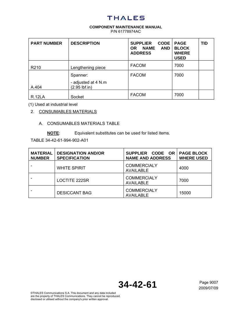
COMPONENT MAINTENANCE MANUAL
P/N 61778974AC
34-42-61 Page 9007
2009/07/09©THALES Communications S.A. This document and any data included are the property of THALES Communications. They cannot be reproduced, disclosed or utilised without the company's prior written approval.
PART NUMBER DESCRIPTION SUPPLIER CODE OR NAME AND ADDRESS
PAGE BLOCK WHERE USED
TID
R210 Lengthening piece FACOM 7000
A.404
Spanner:
- adjusted at 4 N.m (2.95 lbf.in)
FACOM 7000
R.12LA Socket FACOM 7000
(1) Used at industrial level
2. CONSUMABLES MATERIALS
A. CONSUMABLES MATERIALS TABLE
NOTE: Equivalent substitutes can be used for listed items.
TABLE 34-42-61-994-902-A01
MATERIAL NUMBER
DESIGNATION AND/OR SPECIFICATION
SUPPLIER CODE OR NAME AND ADDRESS
PAGE BLOCK WHERE USED
- WHITE SPIRIT
COMMERCIALY AVAILABLE
4000
- LOCTITE 222SR
COMMERCIALY AVAILABLE
7000
- DESICCANT BAG
COMMERCIALY AVAILABLE
15000
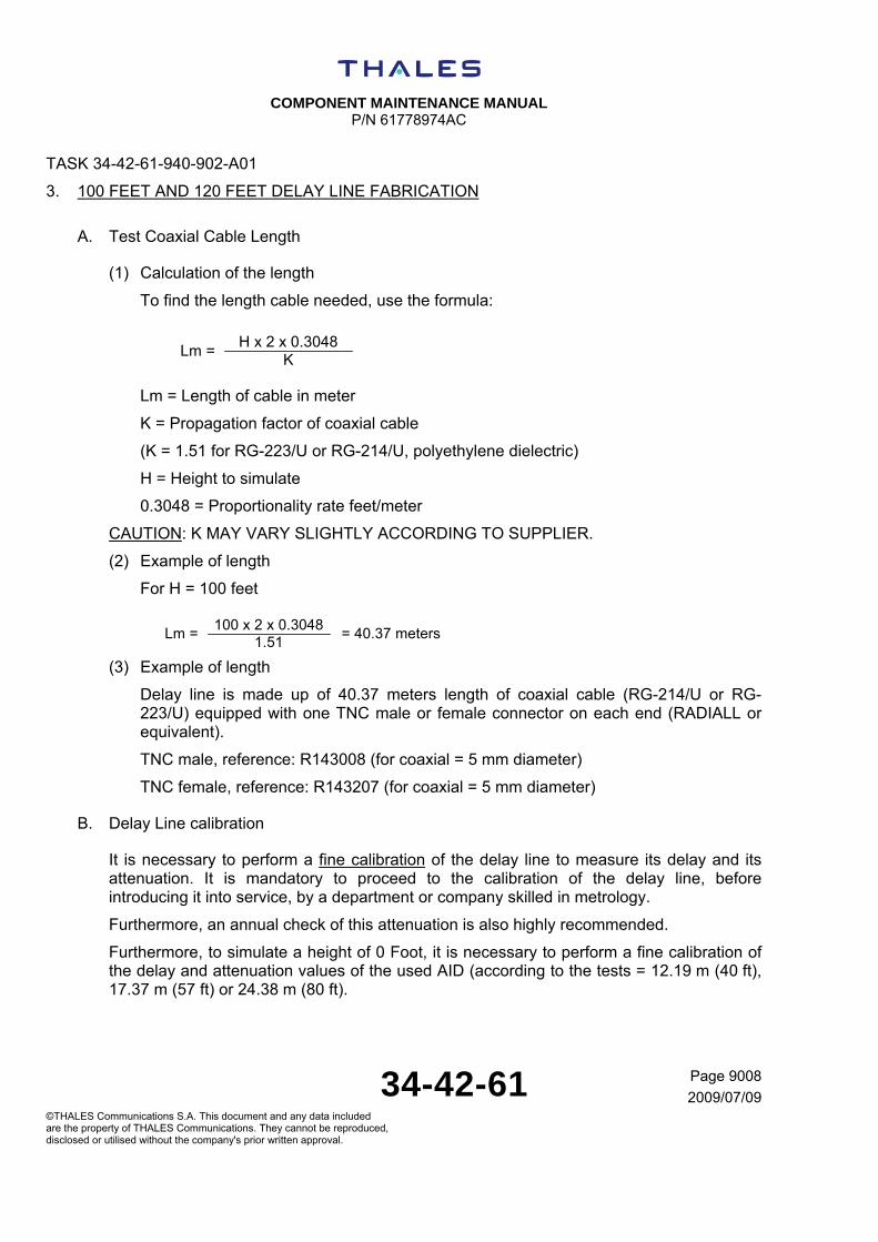
COMPONENT MAINTENANCE MANUAL
P/N 61778974AC
34-42-61 Page 9008
2009/07/09©THALES Communications S.A. This document and any data included are the property of THALES Communications. They cannot be reproduced, disclosed or utilised without the company's prior written approval.
TASK 34-42-61-940-902-A01
3. 100 FEET AND 120 FEET DELAY LINE FABRICATION
A. Test Coaxial Cable Length
(1) Calculation of the length
To find the length cable needed, use the formula:
Lm = Length of cable in meter
K = Propagation factor of coaxial cable
(K = 1.51 for RG-223/U or RG-214/U, polyethylene dielectric)
H = Height to simulate
0.3048 = Proportionality rate feet/meter
CAUTION: K MAY VARY SLIGHTLY ACCORDING TO SUPPLIER.
(2) Example of length
For H = 100 feet
(3) Example of length
Delay line is made up of 40.37 meters length of coaxial cable (RG-214/U or RG-223/U) equipped with one TNC male or female connector on each end (RADIALL or equivalent).
TNC male, reference: R143008 (for coaxial = 5 mm diameter)
TNC female, reference: R143207 (for coaxial = 5 mm diameter)
B. Delay Line calibration
It is necessary to perform a fine calibration of the delay line to measure its delay and its attenuation. It is mandatory to proceed to the calibration of the delay line, before introducing it into service, by a department or company skilled in metrology.
Furthermore, an annual check of this attenuation is also highly recommended.
Furthermore, to simulate a height of 0 Foot, it is necessary to perform a fine calibration of the delay and attenuation values of the used AID (according to the tests = 12.19 m (40 ft), 17.37 m (57 ft) or 24.38 m (80 ft).
Lm =H x 2 x 0.3048
K
Lm =100 x 2 x 0.3048
1.51= 40.37 meters

COMPONENT MAINTENANCE MANUAL
P/N 61778974AC
34-42-61 Page 15001
2009/07/09©THALES Communications S.A. This document and any data included are the property of THALES Communications. They cannot be reproduced, disclosed or utilised without the company's prior written approval.
STORAGE (INCLUDING TRANSPORTATION)
TASK 34-42-61-550-801-A01
1. STORAGE
A. REASON FOR THE JOB
Self-explanatory.
B. JOB SET-UP INFORMATION
(1) TOOLS, FIXTURES AND TEST EQUIPMENT
Not applicable
(2) CONSUMABLES
The table that follows gives the consumables necessary to do the storage of the the AHV1600 Transceiver
NOTE: You can use equivalent consumables as an alternative to those given in the table.
NOTE: Refer to SPECIAL TOOLS, FIXTURES AND EQUIPMENT AND CONSUMABLES for more data.
TABLE 34-42-61-994-151-A01
REFERENCE NAME
No specific Desiccant bag
C. JOB SET-UP
Not applicable.
D. PROCEDURE
SUBTASK 34-42-61-550-001-A01
(1) Short-term Storage
(a) General
Short-term storage gives the specifications for the mechanical and weather protection (to keep the unit clean, dry, etc.) in a continental climate.
With these protections, the unit can be sent by road, rail, sea or air.
(b) Protection

COMPONENT MAINTENANCE MANUAL
P/N 61778974AC
34-42-61 Page 15002
2009/07/09©THALES Communications S.A. This document and any data included are the property of THALES Communications. They cannot be reproduced, disclosed or utilised without the company's prior written approval.
Put a cap on each connector. These caps are supplied by the manufacturer.
(c) Packaging
The package has the components that follow:
- an unsealed primary Kraft paper envelope,
- one or more cardboard box(es), which is (are) put between the primary envelope and the external case,
- wedging material,
- if necessary, a sealed (water runoff) wooden case lined with Kraft paper, or a container (plastic or other material).
Put an identification label on each package to show the storage date and means.
If necessary, put the signed test report and the follow-up card in an envelope. Put this envelope on the package.
(d) Storage
Put the packaged component in a dry room. After a one-year period, examine the unit for damage.
If necessary, do an operation test with the test bench.
SUBTASK 34-42-61-550-002-A01
(2) Long-term Storage
(a) General
Long-term storage gives the specifications for the mechanical and weather protection for a long period of time.
With these protections, the unit can be sent by road, rail, sea and air.
(b) Protection
Put a cap on each connector. These caps are supplied by the manufacturer.
(c) Packaging
Put the unit in a case. Then, put the unit in a waterproof envelope containing a desiccant bag. Heat-seal this envelope.
(d) Storage
Keep the unit in a dry room. After removal from storage, make sure that the unit is serviceable (use the test bench in a workshop).
Make sure that:
- the performances are in the tolerances,
- the connectors and contacts are clean.

COMPONENT MAINTENANCE MANUAL
P/N 61778974AC
34-42-61 INTRO Page 1
2009/07/09©THALES Communications S.A. This document and any data included are the property of THALES Communications. They cannot be reproduced, disclosed or utilised without the company's prior written approval.
ILLUSTRATED PARTS LIST
TASK 34-42-61-879-804-A01
1. INTRODUCTION
A. General
The purpose of this Illustrated Parts List is the identification of equipment assemblies, sub-assemblies, and parts.
It is set up in conformance with the rules set forth in ATA 100.
From time to time, the Illustrated Parts List is revised so as to incorporate recent additions, cancellations and modifications in equipment. Revisions are indicated by an "R" on the right of each revised line, and apply solely to the date of revision.
B. Use of the Illustrated Parts List is revised so as to incorporate recent additions
(1) Publication Format
The IPL is arranged in the following order:
- Introduction,
- List of Manufacturers (VCI - Vendor Code Index),
- Index of circuit symbols (EDI - Equipment Designator Index),
- Alphabetical and Numerical index (NI),
- Illustrated nomenclature of spare parts.
(2) Designation Method
(a) List of manufacturers
The list of manufacturers is alphanumerically arranged according to the manufacturer's code. This list includes the names and addresses of all manufacturers cited in the detailed nomenclature.
(b) Index of circuit symbols
This index contains the relevant reference and diagrams for each circuit symbol, as well as the corresponding marker.
The circuit symbol designation is alphanumerical, and is arranged in the following order:
- dash,
- letters from A thru Z,
- numerals from 0 thru 9.
(c) Alphanumerical index

COMPONENT MAINTENANCE MANUAL
P/N 61778974AC
34-42-61 INTRO Page 2
2009/07/09©THALES Communications S.A. This document and any data included are the property of THALES Communications. They cannot be reproduced, disclosed or utilised without the company's prior written approval.
The manufacturer's reference designation (Part Number) is alphanumerical, and is arranged in the following order:
- dash,
- letters from A thru Z,
- numerals from 0 to 9.
(3) Manufacturer's Reference (PN)
The manufacturer's references (PN) are published in compliance with:
- standards and official specifications now in effect (AFNOR, BNAE, UTE, etc.),
- instructions from the different manufacturers,
- requirements as set forth in ATA 200.
For the non-specific components, the 8, 12 or 15-number reference has been added in the designation text, excluding nomenclatures furnished via computer.
(4) Identification of a Component Part
There are several different ways to identify a component part.
(a) Through the indexes:
1 Knowing the manufacturer's reference (Part Number)
The manufacturer's reference indexes contain the following information about the reference:
- the reference of the part specific to the airline (column left blank),
- the illustrated catalog sequence number (CSN)
Application:
- the quantity per CSN.
2 Knowing the circuit symbol
The circuit symbol index specifies the item reference and the CSN relevant to a given symbol. (See § 3.B for a breakdown of a circuit symbol).
2-150A
Séquence No Figure No
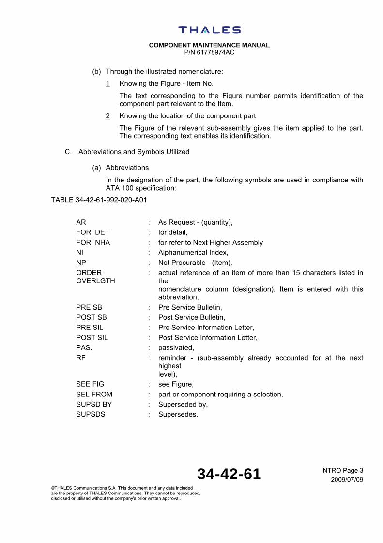
COMPONENT MAINTENANCE MANUAL
P/N 61778974AC
34-42-61 INTRO Page 3
2009/07/09©THALES Communications S.A. This document and any data included are the property of THALES Communications. They cannot be reproduced, disclosed or utilised without the company's prior written approval.
(b) Through the illustrated nomenclature:
1 Knowing the Figure - Item No.
The text corresponding to the Figure number permits identification of the component part relevant to the Item.
2 Knowing the location of the component part
The Figure of the relevant sub-assembly gives the item applied to the part. The corresponding text enables its identification.
C. Abbreviations and Symbols Utilized
(a) Abbreviations
In the designation of the part, the following symbols are used in compliance with ATA 100 specification:
TABLE 34-42-61-992-020-A01
AR : As Request - (quantity),
FOR DET : for detail,
FOR NHA : for refer to Next Higher Assembly
NI : Alphanumerical Index,
NP : Not Procurable - (Item),
ORDER OVERLGTH
: actual reference of an item of more than 15 characters listed in the nomenclature column (designation). Item is entered with this abbreviation,
PRE SB : Pre Service Bulletin,
POST SB : Post Service Bulletin,
PRE SIL : Pre Service Information Letter,
POST SIL : Post Service Information Letter,
PAS. : passivated,
RF : reminder - (sub-assembly already accounted for at the next highest level),
SEE FIG : see Figure,
SEL FROM : part or component requiring a selection,
SUPSD BY : Superseded by,
SUPSDS : Supersedes.

COMPONENT MAINTENANCE MANUAL
P/N 61778974AC
34-42-61 INTRO Page 4
2009/07/09©THALES Communications S.A. This document and any data included are the property of THALES Communications. They cannot be reproduced, disclosed or utilised without the company's prior written approval.
(b) Symbols
The following letters are used in the standard index:
TABLE 34-42-61-992-021-A01
T tera = 1012
G giga = 109
M mega = 106
K kilo = 103
U one = 1
MY milli = 10-3
MU micro = 10-6
N nano = 10-9
P pico = 10-12
The following letters are used in the standard index to indicate tolerances on electronic components:
TABLE 34-42-61-992-022-A01
B 0.1 % G 2 %
C 0.25 % J 5 %
D 0.50 % K 10 %
F 1 % M 20 %
(c) Circuit Symbols
A circuit symbols is made up of:
- 1 or 2 letters specifying the nature of the component part (letter symbol),
- 1 to 3 numerals stating the order code of the component part in the relevant sub-assembly,
D. Pagination
The Illustrated Parts List is made up of sections. The pagination for each section is independent of every other section.
TABLE 34-42-61-992-023-A01
Introduction INTRO Page 1
Vendor Code Index VCI Page 1
Equipment Designator Index EDI Page 1
Alphanumerical index NI Page 1

COMPONENT MAINTENANCE MANUAL
P/N 61778974AC
34-42-61 INTRO Page 5
2009/07/09©THALES Communications S.A. This document and any data included are the property of THALES Communications. They cannot be reproduced, disclosed or utilised without the company's prior written approval.
Detailed nomenclature of spare (Diagram nn) parts Page 1
Basic type diagram Page 10001-0
Type A diagram Page 10001-0A
Type B diagram Page 10001-0B
Nomenclature 1st page of text Page 10001-1
Nomenclature 2nd page of text Page 10001-2

COMPONENT MAINTENANCE MANUAL
P/N 61778974AC
34-42-61 INTRO Page 6
2009/07/09©THALES Communications S.A. This document and any data included are the property of THALES Communications. They cannot be reproduced, disclosed or utilised without the company's prior written approval.
THIS PAGE INTENTIONALLY LEFT BLANK

COMPONENT MAINTENANCE MANUAL
P/N 61778974AC
EQUIPMENT DESIGNATOR INDEX
34-42-61 VCI Page 1
2009/07/09©THALES Communications S.A. This document and any data included are the property of THALES Communications. They cannot be reproduced, disclosed or utilised without the company's prior written approval.
VENDOR CODE NAME ADDRESS
F0110 AFNOR (ASSOCIATION FRANCAISE DE NORMALISATION) 11 AV FRANCIS DE PRESSENCE 93571 LA PLAINE ST DENIS CEDEX France F8300 CIMD (CENTRE D’IDENTIFICATION DES MATERIELS DE LA DEFENSE) RTE DE LAILLE 35170 BRUZ FRANCE

COMPONENT MAINTENANCE MANUAL
P/N 61778974AC
34-42-61 VCI Page 2
2009/07/09©THALES Communications S.A. This document and any data included are the property of THALES Communications. They cannot be reproduced, disclosed or utilised without the company's prior written approval.
THIS PAGE INTENTIONALLY LEFT BLANK

COMPONENT MAINTENANCE MANUAL
P/N 61778974AC
NUMERICAL INDEX
34-42-61 NI Page 1
2009/07/09©THALES Communications S.A. This document and any data included are the property of THALES Communications. They cannot be reproduced, disclosed or utilised without the company's prior written approval.
FIG. ITEM
FIG. ITEM EQUIPMENT
DESIGNATOR EQUIPMENT
DESIGNATOR
K3QIZH0252006A 1 140A 1 170A K3QIZH0252008A 1 50A R9ZT025A 1 60A 1 150A 1 180A UFQIZH025008A 1 20A 1 100A 34MMBX-50-0-1/111 NE 1 -210A 34MMBX-TNC-50-1 1 200A 4679128B 1 -105A 4679129B 1 -185A 5616000B 1 110A 61778312AA 1 -25A 61778974AC 1 -01A 61814651AA 1 -220A 61935014AA 1 -80A 61935016AA 1 160A 61935017AA 1 130A 61935018AA 1 120A 62063831AA 1 40A 62063836AA 1 190A 62095541AA 1 10A 62133420AA 1 90A 62133857AA 1 30A 62133858AA 1 70A

COMPONENT MAINTENANCE MANUAL
P/N 61778974AC
34-42-61 EDI 1001 Page 1
2009/06/25©THALES Communications S.A. This document and any data included are the property of THALES Communications. They cannot be reproduced, disclosed or utilised without the company's prior written approval.
FIG. ITEM
FIG. ITEM EQUIPMENT
DESIGNATOR EQUIPMENT
DESIGNATOR
THIS PAGE INTENTIONALLY LEFT BLANK

COMPONENT MAINTENANCE MANUAL
P/N 61778974AC
34-42-61 EDI 1001 Page 1
2009/06/25©THALES Communications S.A. This document and any data included are the property of THALES Communications. They cannot be reproduced, disclosed or utilised without the company's prior written approval.
FIG. ITEM
FIG. ITEM EQUIPMENT
DESIGNATOR EQUIPMENT
DESIGNATOR

C
OM
PO
NE
NT
MA
INT
EN
AN
CE
MA
NU
AL
P
/N 6
1778
974A
C
ILL
US
TR
AT
ED
PA
RT
S C
AT
AL
OG
TR
AN
SC
EIV
ER
AH
V16
00
Fig
ure
1
34
-42
-61
P
age
1000
1-0
2009
/07/
09©
TH
ALE
S C
omm
unic
atio
ns S
.A.
Thi
s do
cum
ent
and
any
data
incl
uded
ar
e th
e pr
oper
ty o
f TH
ALE
S C
omm
unic
atio
ns.
The
y ca
nnot
be
repr
oduc
ed,
di
sclo
sed
or u
tilis
ed w
ithou
t th
e co
mpa
ny's
prio
r w
ritte
n ap
prov
al.
10 20 30 40
50 60
70
90
100
110
120
130
140
150
160
170
180
170
180
190
200
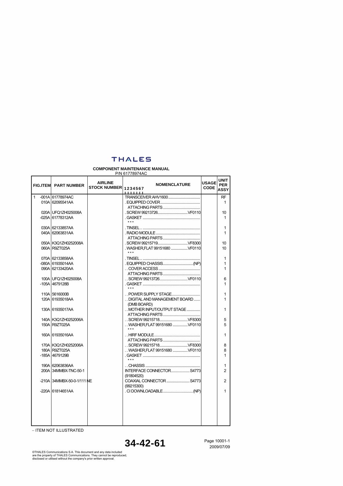
COMPONENT MAINTENANCE MANUAL
P/N 61778974AC
ITEM NOT ILLUSTRATED
34-42-61 Page 10001-1
2009/07/09©THALES Communications S.A. This document and any data included are the property of THALES Communications. They cannot be reproduced, disclosed or utilised without the company's prior written approval.
UNITPER
ASSY
USAGECODE
AIRLINE STOCK NUMBERPART NUMBER FIG.ITEM
1 2 3 4 5 6 7 I I I I I I I
NOMENCLATURE
1 -001A 61778974AC TRANSCEIVER AHV1600.................................... RF 010A 62095541AA . EQUIPPED COVER............................................. 1 ATTACHING PARTS.......................................... 020A UFQ1ZH025008A . SCREW 99213726..................................VF0110 10 -025A 61778312AA . GASKET ................................................................. 1 * * * 030A 62133857AA . TINSEL.. ................................................................. 1 040A 62063831AA . RADIO MODULE.................................................. 1 ATTACHING PARTS.......................................... 050A K3Q1ZH0252008A . SCREW 99215719..................................VF8300 10 060A R9ZT025A . WASHER,FLAT 99151680 ...................VF0110 10 * * * 070A 62133858AA . TINSEL.. ................................................................. 1 -080A 61935014AA . EQUIPPED CHASSIS..................................(NP) 1 090A 62133420AA . . COVER ACCESS............................................... 1 ATTACHING PARTS.......................................... 100A UFQ1ZH025008A . . SCREW 99213726................................VF0110 6 -105A 4679128B . GASKET ................................................................. 1 * * * 110A 5616000B . . POWER SUPPLY STAGE................................ 1 120A 61935018AA . . DIGITAL AND MANAGEMENT BOARD....... 1 (DMB BOARD) 130A 61935017AA . . MOTHER INPUT/OUTPUT STAGE............... 1 ATTACHING PARTS.......................................... 140A K3Q1ZH0252006A . . SCREW 99215718................................VF8300 5 150A R9ZT025A . . WASHER,FLAT 99151680 .................VF0110 5 * * * 160A 61935016AA . . HIRF MODULE.................................................... 1 ATTACHING PARTS.......................................... 170A K3Q1ZH0252006A . . SCREW 99215718................................VF8300 8 180A R9ZT025A . . WASHER,FLAT 99151680 .................VF0110 8 -185A 4679129B . GASKET ................................................................. 1 * * * 190A 62063836AA . . CHASSIS.............................................................. 1 200A 34MMBX-TNC-50-1 INTERFACE CONNECTOR.....................S4773 2 (91804520) -210A 34MMBX-50-0-1/111 NE COAXIAL CONNECTOR..........................S4773 2 (99215300) -220A 61814651AA . CI DOWNLOADABLE..................................(NP) 1

COMPONENT MAINTENANCE MANUAL
P/N 61778974AC
34-42-61 Page 10001-2
2009/07/09©THALES Communications S.A. This document and any data included are the property of THALES Communications. They cannot be reproduced, disclosed or utilised without the company's prior written approval.
THIS PAGE INTENTIONALLY LEFT BLANK