Embed Size (px)
Citation preview
I94GC-IA Setup Manual
FCC Information and Copyright
This equipment has been tested and found to comply with the limits of a Class B digital device, pursuant to Part 15 of the FCC Rules. These limits are designed to provide reasonable protection against harmful interference in a residential installation. This equipment generates, uses, and can radiate radio frequency energy and, if not installed and used in accordance with the instructions, may cause harmful interference to radio communications. There is no guarantee that interference will not occur in a particular installation.
The vendor makes no representations or warranties with respect to the contents here and specially disclaims any implied warranties of merchantability or fitness for any purpose. Further the vendor reserves the right to revise this publication and to make changes to the contents here without obligation to notify any party beforehand.
Duplication of this publication, in part or in whole, is not allowed without first obtaining the vendor’s approval in writing.
The content of this user’s manual is subject to be changed without notice and we will not be responsible for any mistakes found in this user’s manual. All the brand and product names are trademarks of their respective companies.
Table of Contents
Chapter 1: Introduction.......................................... 3
1.1 Before You Start .................................................................................3 1.2 Package Checklist ...............................................................................3 1.3 Mainboard Specifications...................................................................4 1.4 Rear Panel ...........................................................................................5 1.5 Mainboard Layout ..............................................................................6
Chapter 2: Installation ........................................... 7 2.1 CPU ......................................................................................................7 2.2 Fan Headers ........................................................................................7 2.3 System Memory ..................................................................................8 2.4 Power Supply ......................................................................................9 2.5 Onboard Slot/Connector/Header/Jumper .......................................10
Chapter 3: Useful Help ......................................... 23 3.1 Driver Installation Note ....................................................................23 3.2 AMI BIOS Beep Code ........................................................................24 3.3 Troubleshooting................................................................................25
I94GC-IA
3
CHAPTER 1: INTRODUCTION 1.1 BEFORE YOU START
Thank you for choosing our product. Before you start installing the mainboard, please make sure you follow the instructions below:
Prepare a dry and stable working environment with sufficient lighting.
Always disconnect the system from power outlet before operation.
Before you take the mainboard out from anti-static bag, ground yourself properly by touching any safely grounded appliance, or use grounded wrist strap to remove the static charge.
Avoid touching the components on mainboard or the rear side of the board unless necessary. Hold the board on the edge, do not try to bend or flex the board.
Do not leave any unfastened small parts inside the case after installation. Loose parts will cause short circuits which may damage the equipment.
Keep the system from dangerous area, such as heat source, humid air, and water.
Please switch on/off the machine normally. That is, DO NOT pull out power cord directly from the mainboard or the system may damage.
1.2 PACKAGE CHECKLIST Mini-ITX Mainboard x 1
Fully Setup Driver CD x 1
I/O Bracket x 1
IDE Cable x 1 (Optional)
SATA Cable x 1 (Optional)
Mini-ITX Mainboard Manual
4
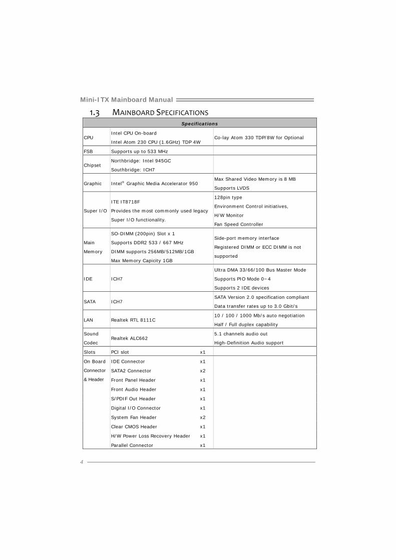
1.3 MAINBOARD SPECIFICATIONS Specifications
CPU Intel CPU On-board
Intel Atom 230 CPU (1.6GHz) TDP 4W Co-lay Atom 330 TDP/8W for Optional
FSB Supports up to 533 MHz
Chipset Northbridge: Intel 945GC
Southbridge: ICH7
Graphic Intel® Graphic Media Accelerator 950 Max Shared Video Memory is 8 MB
Supports LVDS
Super I/O
ITE IT8718F
Provides the most commonly used legacy
Super I/O functionality.
128pin type
Environment Control initiatives,
H/W Monitor
Fan Speed Controller
Main
Memory
SO-DIMM (200pin) Slot x 1
Supports DDR2 533 / 667 MHz
DIMM supports 256MB/512MB/1GB
Max Memory Capicity 1GB
Side-port memory interface
Registered DIMM or ECC DIMM is not
supported
IDE ICH7
Ultra DMA 33/66/100 Bus Master Mode
Supports PIO Mode 0~4
Supports 2 IDE devices
SATA ICH7 SATA Version 2.0 specification compliant
Data transfer rates up to 3.0 Gbit/s
LAN Realtek RTL 8111C 10 / 100 / 1000 Mb/s auto negotiation
Half / Full duplex capability
Sound
Codec Realtek ALC662
5.1 channels audio out
High-Definition Audio support
Slots PCI slot x1
IDE Connector x1
SATA2 Connector x2
Front Panel Header x1
Front Audio Header x1
S/PDIF Out Header x1
Digital I/O Connector x1
System Fan Header x2
Clear CMOS Header x1
H/W Power Loss Recovery Header x1
On Board
Connector
& Header
Parallel Connector x1
I94GC-IA
5
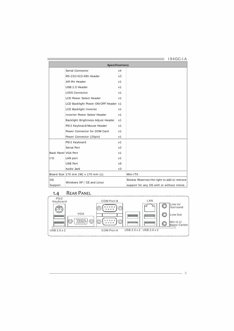
Specifications
Serial Connector x4
RS-232/422/485 Header x2
JIR Pin Header x1
USB 2.0 Header x1
LVDS Connector x1
LCD Power Select Header x1
LCD Backlight Power ON/OFF Header x1
LCD Backlight Inverter x1
Inverter Power Select Header x1
Backlight Brightness Adjust Header x1
PS/2 Keyboard/Mouse Header x1
Power Connector for DOM Card x1
Power Connector (20pin) x1
Back Panel
I/O
PS/2 Keyboard x1
Serial Port x2
VGA Port x1
LAN port x1
USB Port x6
Audio Jack x3
Board Size 170 mm (W) x 170 mm (L) Mini-ITX
OS
Support Windows XP / CE and Linux
Biostar Reserves the right to add or remove
support for any OS with or without notice.
1.4 REAR PANEL PS/2 Keyboard LAN
COM Port A
Line In/Surround
Line Out
Mic In 1/Bass/ Center
VGA
USB 2.0 x 2
COM Port B
USB 2.0 x 2USB 2.0 x 2
Mini-ITX Mainboard Manual
6
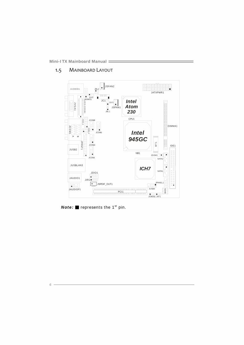
1.5 MAINBOARD LAYOUT
J U S B K B 1
JVG
A1
JCO
M1
JUSB2
JUSBLAN3
JAUDIO1
JAUDIOF1
JSPDIF_OUT1
JIR1
JDIO1
JCOM6
JCOM5
JCOM4
JCOM3JS
EL
1
JSE
L2
JPR
NT
1
JKBMS1
PCI1
JCMOS1 JAT1
BIO
S
IDE1
SATA1
SATA2B
T1
JDOM1
DIMMA1
JUSB4
JPANEL1
Intel945GC
ICH7
JATXPWR1
JSFAN1
LVD
S-C
ON
N1
JC1JLV1
JBL1
JLV2
JBL2JSFAN2
IntelAtom230CPU1
NB1
A B
Note: represents the 1■ st pin.
I94GC-IA
7
CHAPTER 2: INSTALLATION 2.1 CPU
The mainboard includes an embedded Intel Atom 230 processor, and a heatsink has been installed to provide sufficient cooling.
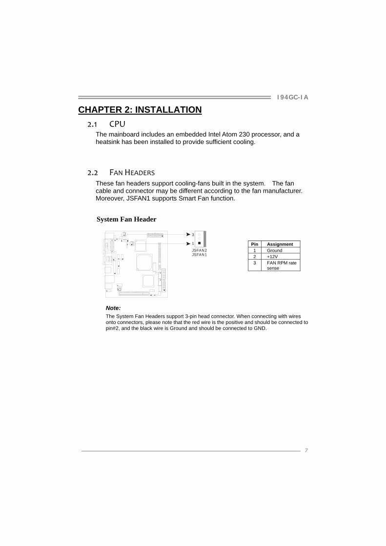
2.2 FAN HEADERS These fan headers support cooling-fans built in the system. The fan cable and connector may be different according to the fan manufacturer. Moreover, JSFAN1 supports Smart Fan function.
System Fan Header
Pin Assignment 1 Ground 2 +12V 3 FAN RPM rate
sense
1
3
JSFAN2JSFAN1
Note: The System Fan Headers support 3-pin head connector. When connecting with wires onto connectors, please note that the red wire is the positive and should be connected to pin#2, and the black wire is Ground and should be connected to GND.
Mini-ITX Mainboard Manual
8
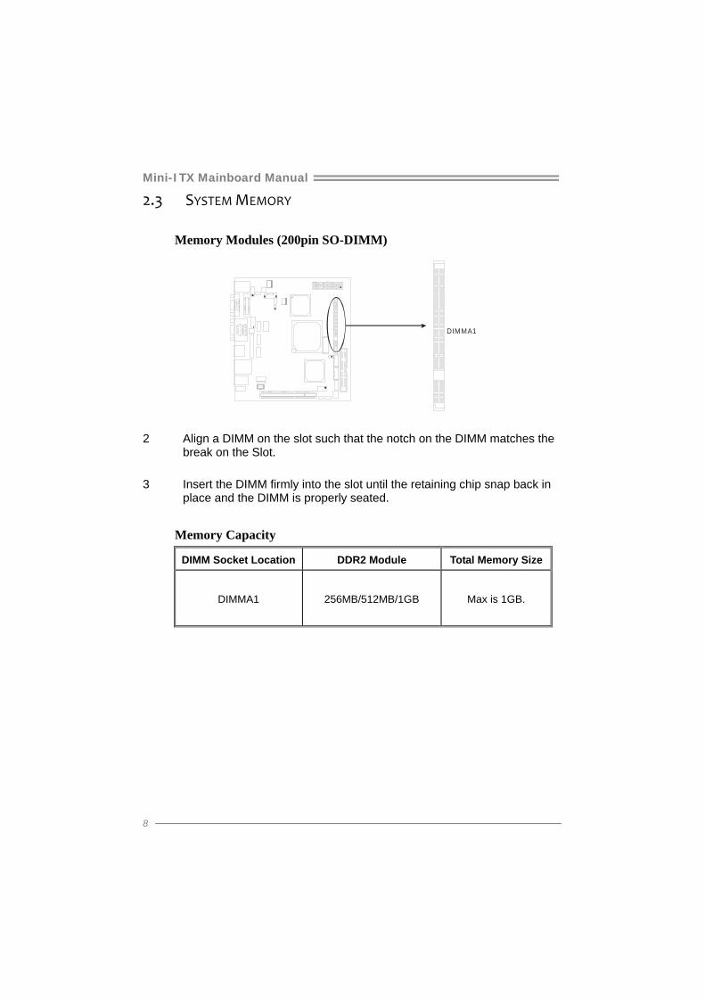
2.3 SYSTEM MEMORY
Memory Modules (200pin SO-DIMM)
DIMMA1
2 Align a DIMM on the slot such that the notch on the DIMM matches the break on the Slot.
3 Insert the DIMM firmly into the slot until the retaining chip snap back in
place and the DIMM is properly seated.
Memory Capacity
DIMM Socket Location DDR2 Module Total Memory Size
DIMMA1 256MB/512MB/1GB Max is 1GB.
I94GC-IA
9
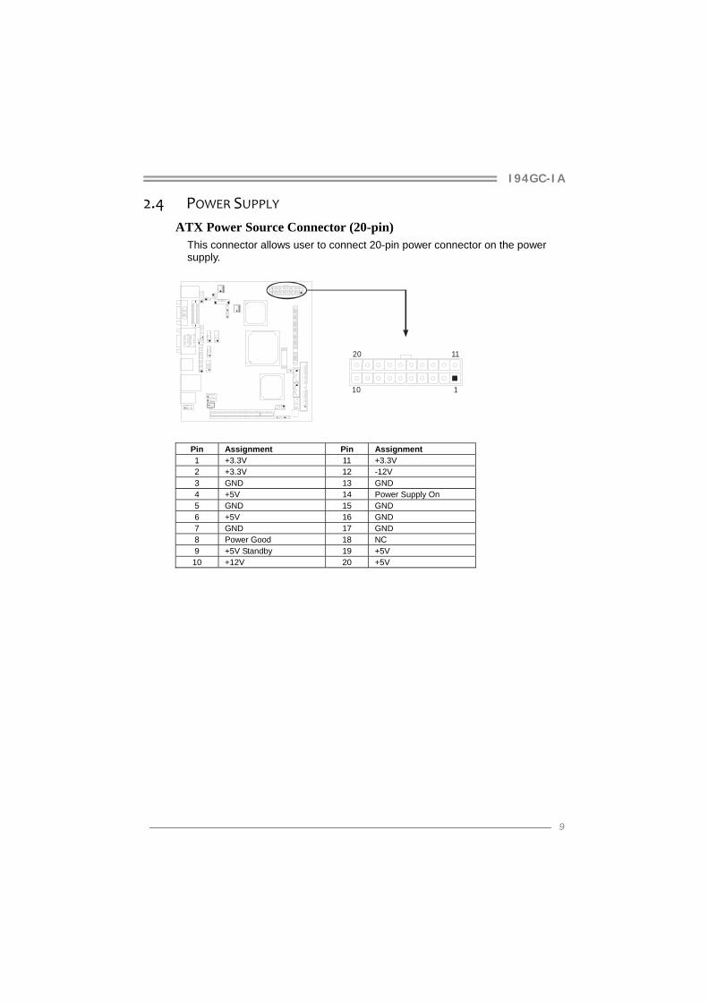
2.4 POWER SUPPLY ATX Power Source Connector (20-pin)
This connector allows user to connect 20-pin power connector on the power supply.
110
1120
Pin Assignment Pin Assignment 1 +3.3V 11 +3.3V 2 +3.3V 12 -12V 3 GND 13 GND 4 +5V 14 Power Supply On 5 GND 15 GND 6 +5V 16 GND 7 GND 17 GND 8 Power Good 18 NC 9 +5V Standby 19 +5V 10 +12V 20 +5V
Mini-ITX Mainboard Manual
10
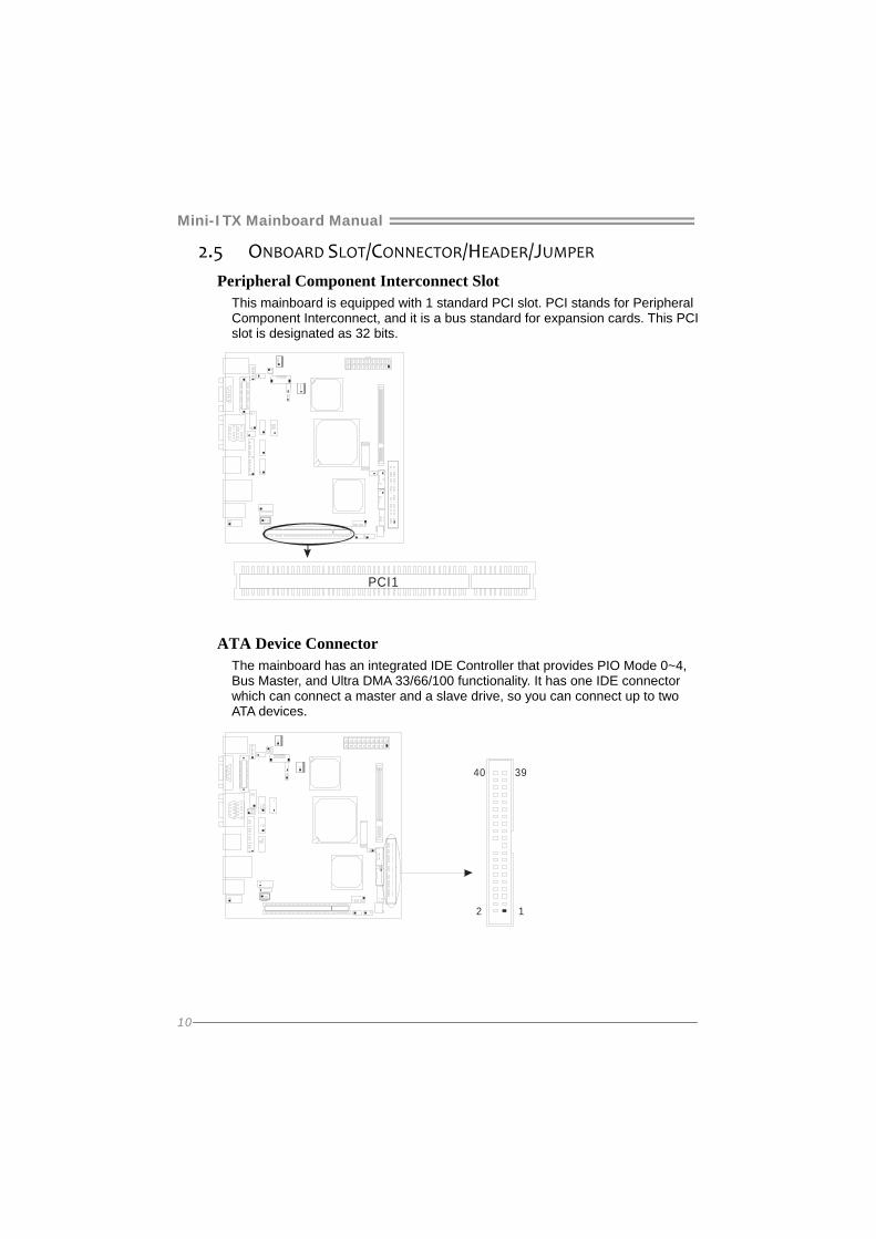
2.5 ONBOARD SLOT/CONNECTOR/HEADER/JUMPER Peripheral Component Interconnect Slot
This mainboard is equipped with 1 standard PCI slot. PCI stands for Peripheral Component Interconnect, and it is a bus standard for expansion cards. This PCI slot is designated as 32 bits.
PCI1
ATA Device Connector
The mainboard has an integrated IDE Controller that provides PIO Mode 0~4, Bus Master, and Ultra DMA 33/66/100 functionality. It has one IDE connector which can connect a master and a slave drive, so you can connect up to two ATA devices.
12
3940
I94GC-IA
11
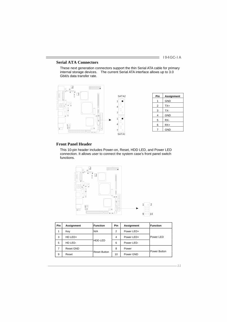
Serial ATA Connectors These next generation connectors support the thin Serial ATA cable for primary internal storage devices. The current Serial ATA interface allows up to 3.0 Gbit/s data transfer rate.
Pin Assignment
1 GND
2 TX+
3 TX-
4 GND
5 RX-
6 RX+
7 GND
1
4
7
1
4
7
SATA2
SATA1
Front Panel Header
This 10-pin header includes Power-on, Reset, HDD LED, and Power LED connection. It allows user to connect the system case’s front panel switch functions.
9
1 2
10 Pin Assignment Function Pin Assignment Function
1 Key N/A 2 Power LED+
3 HD LED+ 4 Power LED+
5 HD LED- HDD LED
6 Power LED-
Power LED
7 Reset GND 8 Power
9 Reset Reset Button
10 Power GND Power Button
Mini-ITX Mainboard Manual
12
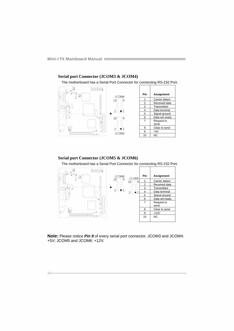
Serial port Connector (JCOM3 & JCOM4) The motherboard has a Serial Port Connector for connecting RS-232 Port.
Pin
Assignment
1 Carrier detect 2 Received data 3 Transmitted 4 Data terminal 5 Signal ground 6 Data set ready 7 Request to
send 8 Clear to send 9 +5V
1
9
2
10
1
9
2
10
JCOM4
JCOM3 10 NC
Serial port Connector (JCOM5 & JCOM6) The motherboard has a Serial Port Connector for connecting RS-232 Port.
Pin
Assignment
1 Carrier detect 2 Received data 3 Transmitted 4 Data terminal 5 Signal ground 6 Data set ready 7 Request to
send 8 Clear to send 9 +12V
1
9
2
10
1
9
2
10
JCOM6JCOM5
10 NC
Note: Please notice Pin 9 of every serial port connector. JCOM3 and JCOM4: +5V; JCOM5 and JCOM6: +12V.
I94GC-IA
13
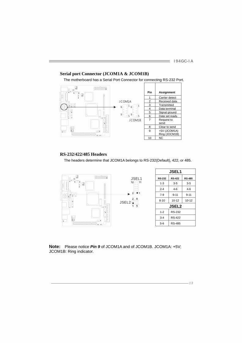
Serial port Connector (JCOM1A & JCOM1B)
The motherboard has a Serial Port Connector for connecting RS-232 Port.
Pin
Assignment
1 Carrier detect 2 Received data 3 Transmitted 4 Data terminal 5 Signal ground 6 Data set ready 7 Request to
send 8 Clear to send 9 +5V (JCOM1A)
Ring (JOCM1B)
JCOM1A
JCOM1B
1 1
5 5
6 6
9 9
10 NC
RS-232/422/485 Headers The headers determine that JCOM1A belongs to RS-232(Default), 422, or 485.
JSEL1 RS-232 RS-422 RS-485
1-3 3-5 3-5
2-4 4-6 4-6
7-9 9-11 9-11
8-10 10-12 10-12
JSEL2
1-2 RS-232
3-4 RS-422
5-6 RS-485
JSEL2
JSEL1
Note: Please notice Pin 9 of JCOM1A and of JCOM1B. JCOM1A: +5V; JCOM1B: Ring indicator.
Mini-ITX Mainboard Manual
14
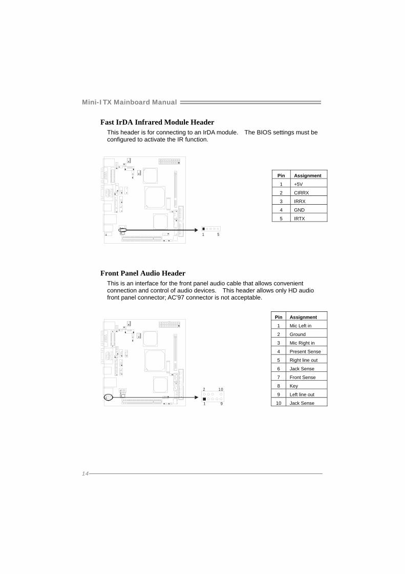
Fast IrDA Infrared Module Header
This header is for connecting to an IrDA module. The BIOS settings must be configured to activate the IR function.
Pin Assignment
1 +5V
2 CIRRX
3 IRRX
4 GND
5 IRTX
1 5
Front Panel Audio Header
This is an interface for the front panel audio cable that allows convenient connection and control of audio devices. This header allows only HD audio front panel connector; AC’97 connector is not acceptable.
Pin Assignment
1 Mic Left in
2 Ground
3 Mic Right in
4 Present Sense
5 Right line out
6 Jack Sense
7 Front Sense
8 Key
9 Left line out
10 Jack Sense 1
2
9
10
I94GC-IA
15
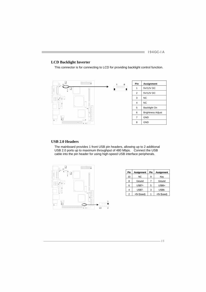
LCD Backlight Inverter
This connector is for connecting to LCD for providing backlight control function.
Pin Assignment
1 5V/12V DC
2 5V/12V DC
3 NC
4 NC
5 Backlight On
6 Brightness Adjust
7 GND
8 GND
USB 2.0 Headers The mainboard provides 1 front USB pin headers, allowing up to 2 additional USB 2.0 ports up to maximum throughput of 480 Mbps. Connect the USB cable into the pin header for using high-speed USB interface peripherals.
Pin Assignment Pin Assignment
10 NC 9 Key
8 Ground 7 Ground
6 USB7+ 5 USB6+
4 USB7- 3 USB6-
2 +5V (fused) 1 +5V (fused)
1
210
Mini-ITX Mainboard Manual
16
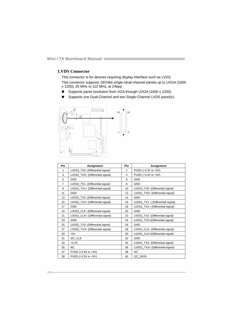
LVDS Connector This connector is for devices requiring display interface such as LVDS. This connector supports 18/24bit single-/dual-channel panels up to UXGA (1600 x 1200), 25 MHz to 112 MHz; at 24bpp
Supports panel resolution from VGA through UXGA (1600 x 1200). Supports one Dual-Channel and two Single-Channel LVDS panel(s).
21
4039
Pin Assignment Pin Assignment 1 LVDS2_TX0- (Differential signal) 2 PVDD (+3.3V or +5V) 3 LVDS2_TX0+ (Differential signal) 4 PVDD (+3.3V or +5V) 5 GND 6 GND 7 LVDS2_TX1- (Differential signal) 8 GND 9 LVDS2_TX1+ (Differential signal) 10 LVDS1_TX0- (Differential signal) 11 GND 12 LVDS1_TX0+ (Differential signal) 13 LVDS2_TX2- (Differential signal) 14 GND 15 LVDS2_TX2+ (Differential signal) 16 LVDS1_TX1- ( (Differential signal) 17 GND 18 LVDS1_TX1+ (Differential signal) 19 LVDS2_CLK- (Differential signal) 20 GND 21 LVDS2_CLK+ (Differential signal) 22 LVDS1_TX2- (Differential signal) 23 GND 24 LVDS1_TX2+(Differential signal) 25 LVDS2_TX3- (Differential signal) 26 GND 27 LVDS2_TX3+ (Differential signal) 28 LVDS1_CLK- (Differential signal) 29 +5V 30 LVDS1_CLK+(Differential signal) 31 I2C_CLK 32 GND 33 +3.3V 34 LVDS1_TX3- (Differential signal) 35 NC 36 LVDS1_TX3+ (Differential signal) 37 PVDD (+3.3V or +5V) 38 NC 39 PVDD (+3.3V or +5V) 40 I2C_DATA
I94GC-IA
17
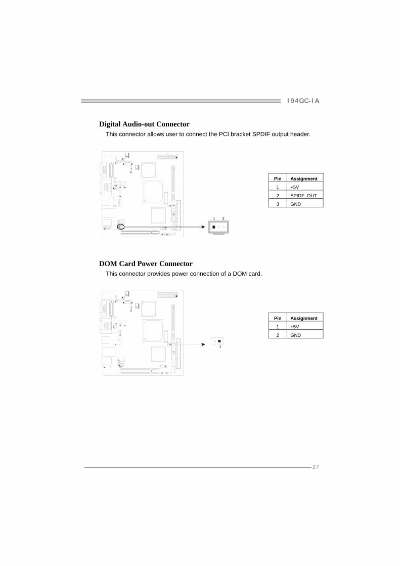
Digital Audio-out Connector
This connector allows user to connect the PCI bracket SPDIF output header.
Pin Assignment
1 +5V
2 SPIDF_OUT
3 GND
1 3
DOM Card Power Connector This connector provides power connection of a DOM card.
Pin Assignment
1 +5V
2 GND
1
Mini-ITX Mainboard Manual
18
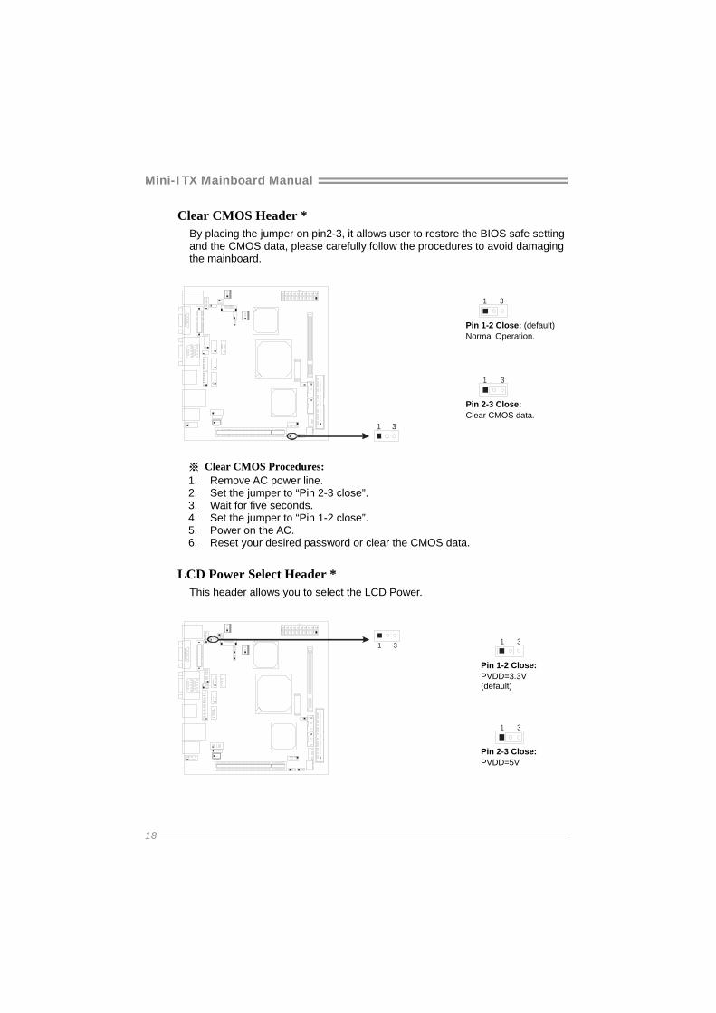
Clear CMOS Header *
By placing the jumper on pin2-3, it allows user to restore the BIOS safe setting and the CMOS data, please carefully follow the procedures to avoid damaging the mainboard.
1 3
Pin 1-2 Close: (default) Normal Operation.
1 3
1 3
Pin 2-3 Close: Clear CMOS data.
※ Clear CMOS Procedures: 1. Remove AC power line. 2. Set the jumper to “Pin 2-3 close”. 3. Wait for five seconds. 4. Set the jumper to “Pin 1-2 close”. 5. Power on the AC. 6. Reset your desired password or clear the CMOS data.
LCD Power Select Header *
This header allows you to select the LCD Power.
1 3
Pin 1-2 Close: PVDD=3.3V (default)
1 3
1 3
Pin 2-3 Close: PVDD=5V
I94GC-IA
19
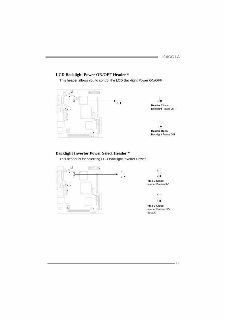
LCD Backlight Power ON/OFF Header * This header allows you to control the LCD Backlight Power ON/OFF.
1 Header Close: Backlight Power OFF
1
1 Header Open: Backlight Power ON
Backlight Inverter Power Select Header * This header is for selecting LCD Backlight Inverter Power.
1
3
Pin 1-2 Close: Inverter Power=5V
1
3
1
3
Pin 2-3 Close: Inverter Power=12V (default)
Mini-ITX Mainboard Manual
20
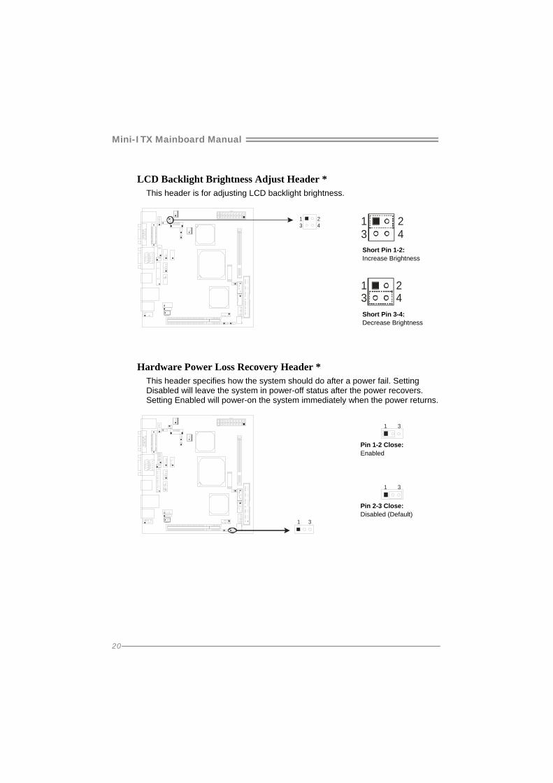
LCD Backlight Brightness Adjust Header * This header is for adjusting LCD backlight brightness.
1 23 4 Short Pin 1-2: Increase Brightness
1 23 4
1 23 4
Short Pin 3-4: Decrease Brightness
Hardware Power Loss Recovery Header * This header specifies how the system should do after a power fail. Setting Disabled will leave the system in power-off status after the power recovers. Setting Enabled will power-on the system immediately when the power returns.
1 3
Pin 1-2 Close: Enabled
1 3
1 3
Pin 2-3 Close: Disabled (Default)
I94GC-IA
21
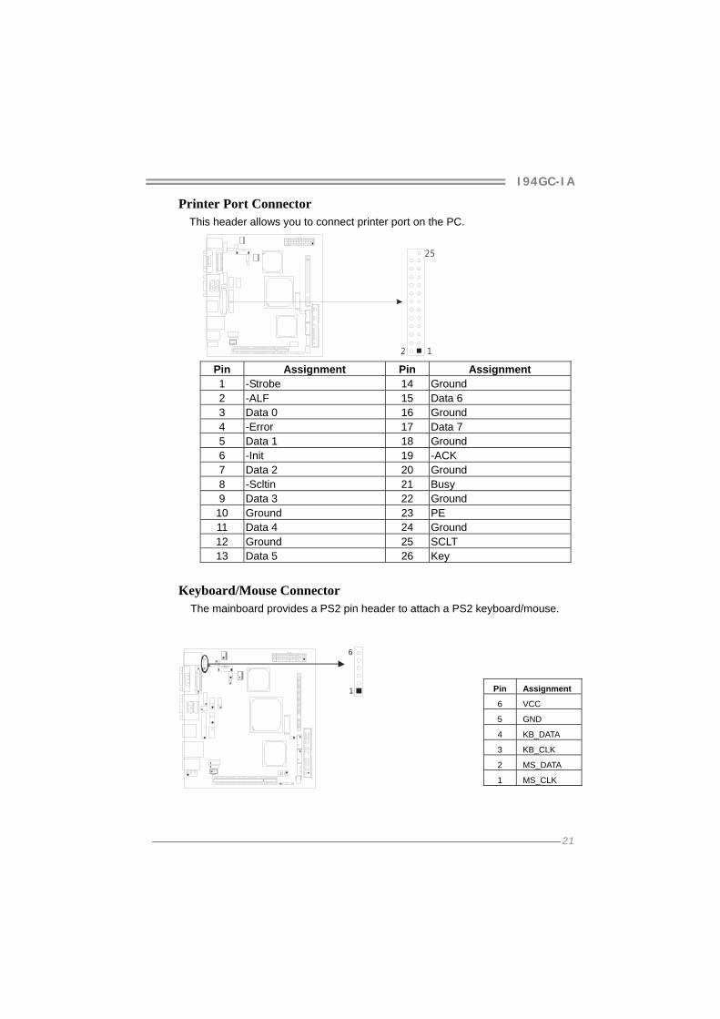
Printer Port Connector This header allows you to connect printer port on the PC.
1
25
2 Pin Assignment Pin Assignment 1 -Strobe 14 Ground 2 -ALF 15 Data 6 3 Data 0 16 Ground 4 -Error 17 Data 7 5 Data 1 18 Ground 6 -Init 19 -ACK 7 Data 2 20 Ground 8 -Scltin 21 Busy 9 Data 3 22 Ground
10 Ground 23 PE 11 Data 4 24 Ground 12 Ground 25 SCLT 13 Data 5 26 Key
Keyboard/Mouse Connector
The mainboard provides a PS2 pin header to attach a PS2 keyboard/mouse.
Pin Assignment
6 VCC
5 GND
4 KB_DATA
3 KB_CLK
2 MS_DATA
1 MS_CLK
1
6
Mini-ITX Mainboard Manual
22
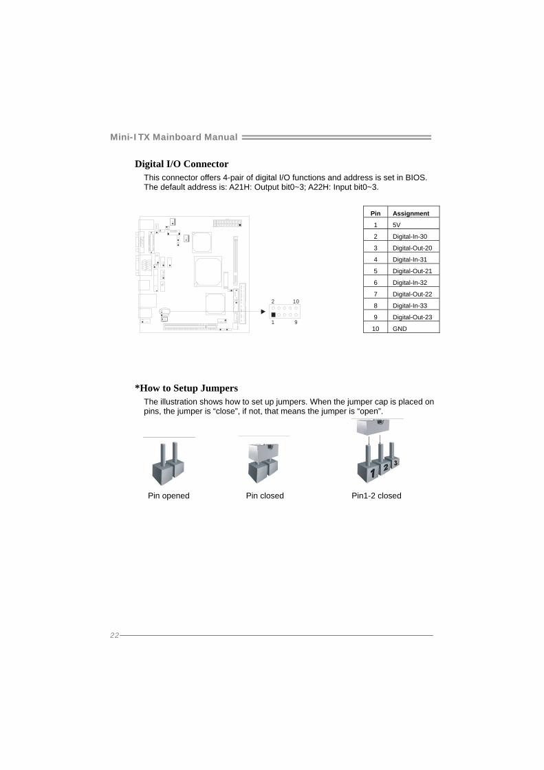
Digital I/O Connector
This connector offers 4-pair of digital I/O functions and address is set in BIOS. The default address is: A21H: Output bit0~3; A22H: Input bit0~3.
Pin Assignment
1 5V
2 Digital-In-30
3 Digital-Out-20
4 Digital-In-31
5 Digital-Out-21
6 Digital-In-32
7 Digital-Out-22
8 Digital-In-33
9 Digital-Out-23
10 GND 1
2
9
10
*How to Setup Jumpers The illustration shows how to set up jumpers. When the jumper cap is placed on pins, the jumper is “close”, if not, that means the jumper is “open”.
Pin opened Pin closed Pin1-2 closed
I94GC-IA
23
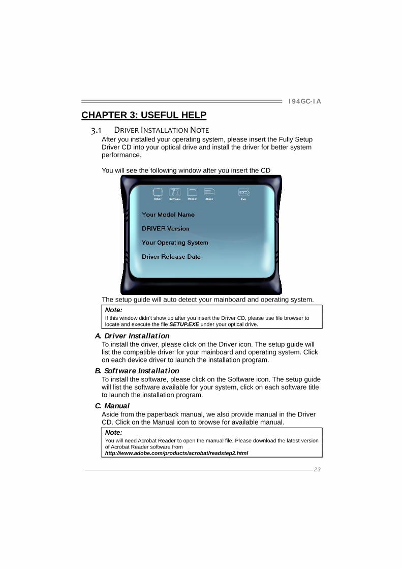
CHAPTER 3: USEFUL HELP 3.1 DRIVER INSTALLATION NOTE
After you installed your operating system, please insert the Fully Setup Driver CD into your optical drive and install the driver for better system performance. You will see the following window after you insert the CD
The setup guide will auto detect your mainboard and operating system. Note: If this window didn’t show up after you insert the Driver CD, please use file browser to locate and execute the file SETUP.EXE under your optical drive.
A. Driver Installation To install the driver, please click on the Driver icon. The setup guide will list the compatible driver for your mainboard and operating system. Click on each device driver to launch the installation program.
B. Software Installation To install the software, please click on the Software icon. The setup guide will list the software available for your system, click on each software title to launch the installation program.
C. Manual Aside from the paperback manual, we also provide manual in the Driver CD. Click on the Manual icon to browse for available manual. Note: You will need Acrobat Reader to open the manual file. Please download the latest version of Acrobat Reader software from http://www.adobe.com/products/acrobat/readstep2.html
Mini-ITX Mainboard Manual
24
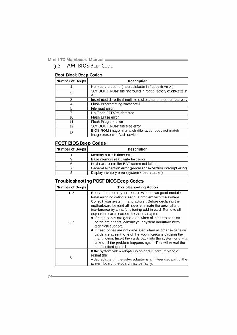
3.2 AMI BIOS BEEP CODE
Boot Block Beep Codes Number of Beeps Description
1 No media present. (Insert diskette in floppy drive A:)
2 “AMIBOOT.ROM” file not found in root directory of diskette in A:
3 Insert next diskette if multiple diskettes are used for recovery 4 Flash Programming successful 5 File read error 7 No Flash EPROM detected
10 Flash Erase error 11 Flash Program error 12 “AMIBOOT.ROM” file size error
13 BIOS ROM image mismatch (file layout does not match image present in flash device)
POST BIOS Beep Codes Number of Beeps Description
1 Memory refresh timer error 3 Base memory read/write test error 6 Keyboard controller BAT command failed 7 General exception error (processor exception interrupt error) 8 Display memory error (system video adapter)
Troubleshooting POST BIOS Beep Codes Number of Beeps Troubleshooting Action
1, 3 Reseat the memory, or replace with known good modules.
6, 7
Fatal error indicating a serious problem with the system. Consult your system manufacturer. Before declaring the motherboard beyond all hope, eliminate the possibility of interference by a malfunctioning add-in card. Remove all expansion cards except the video adapter.
If beep codes are generated when all other expansion cards are absent, consult your system manufacturer’s technical support. If beep codes are not generated when all other expansion cards are absent, one of the add-in cards is causing the malfunction. Insert the cards back into the system one at a time until the problem happens again. This will reveal the malfunctioning card.
8
If the system video adapter is an add-in card, replace or reseat the video adapter. If the video adapter is an integrated part of the system board, the board may be faulty.
I94GC-IA
25
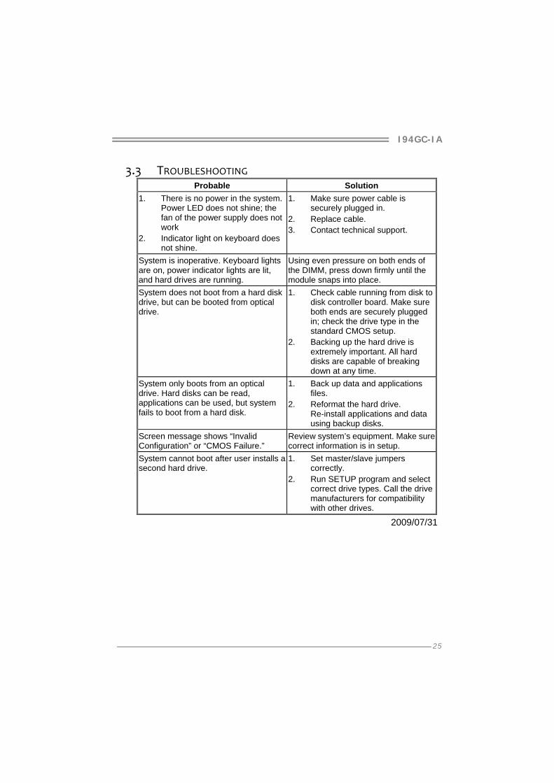
3.3 TROUBLESHOOTING Probable Solution
1. There is no power in the system. Power LED does not shine; the fan of the power supply does not work
2. Indicator light on keyboard does not shine.
1. Make sure power cable is securely plugged in.
2. Replace cable. 3. Contact technical support.
System is inoperative. Keyboard lights are on, power indicator lights are lit, and hard drives are running.
Using even pressure on both ends of the DIMM, press down firmly until the module snaps into place.
System does not boot from a hard disk drive, but can be booted from optical drive.
1. Check cable running from disk to disk controller board. Make sure both ends are securely plugged in; check the drive type in the standard CMOS setup.
2. Backing up the hard drive is extremely important. All hard disks are capable of breaking down at any time.
System only boots from an optical drive. Hard disks can be read, applications can be used, but system fails to boot from a hard disk.
1. Back up data and applications files.
2. Reformat the hard drive. Re-install applications and data using backup disks.
Screen message shows “Invalid Configuration” or “CMOS Failure.”
Review system’s equipment. Make sure correct information is in setup.
System cannot boot after user installs a second hard drive.
1. Set master/slave jumpers correctly.
2. Run SETUP program and select correct drive types. Call the drive manufacturers for compatibility with other drives.
2009/07/31