Embed Size (px)
Citation preview
EPSON®
LQ-800 and LQ-1000 Printers
User's Manual
FCC COMPLIANCE STATEMENTFOR AMERICAN USERS
This equipment generates and uses radio frequency energy and if not installed and usedproperly, that is, in strict accordance with the manufacturer’s instructions, may causeinterference to radio and television reception. It has been type tested and found to complywith the limits for a Class B computing device in accordance with the specifications inSubpart J of part 15 of FCC Rules, which are designed to provide reasonable protectionagainst such interference in a residential installation. However, there is no guarantee thatinterference will not occur in a particular installation. If this equipment does cause inter-ference to radio or television reception, which can be determined by turning the equip-ment off and on, the user is encouraged to try to correct the interference by one or more ofthe following measures:
- Reorient the receiving antenna- Relocate the computer with respect to the receiver- Plug the computer into a different outlet so that the computer and receiver are on
different branch circuits.
If necessary, the user should consult the dealer or an experienced radio/television techni-cian for additional suggestions. The user may find the following booklet prepared by theFederal Communications Commission helpful:
“How to Identify and Resolve Radio-TV Interference Problems.”
This booklet is available from the U.S. Government Printing Office, Washington, DC20402. Stock No. 004-000-00345-4.
WARNING
The connection of a non-shielded printer interface cable to this printer will invali-date the FCC Certification of this device and may cause interference levels whichexceed the limits established by the FCC for this equipment. If this equipment hasmore than one interface connector, do not leave cables connected to unused inter-faces.
All rights reserved. No part of this publication may be reproduced, stored in a retrievalsystem, or transmitted, in any form or by any means, mechanical, photocopying, record-ing or otherwise, without the prior written permission of Seiko Epson Corporation. Nopatent liability is assumed with respect to the use of the information contained herein.While every precaution has been taken in the preparation of this book, Seiko EpsonCorporation assumes no responsibility for errors or omissions. Neither is any liabilityassumed for damages resulting from the use of the information contained herein.
Apple is a registered trademark of Apple Computer, Inc.Applesoft is a trademark of Apple Computer, Inc.Centronics is a registered trademark of Data Computer Corporation.Epson is a registered trademark of Seiko Epson Corporation.IBM is a registered trademark of International Business Machines Corporation.Microsoft is a trademark of Microsoft Corporation.QX-IO is a registered trademark, and QX is a trademark of Epson America, Inc.
Copyright © 1985 by Seiko Epson CorporationNagano, Japan
ii
Contents
Introduction . . . . . . . . . . . . . . . . . . . . . . . . . . . . . . . . . . . Intro-1
1
2
Setting Up Your LQ Printer . . . . . . . . . . . . . . . . . . . . .Unpacking Your Printer . . . . . . . . . . . . . . . . . . . . . . . .
Installing the paper feed knob . . . . . . . . . . . . . . . . .Selecting the Right Location . . . . . . . . . . . . . . . . . . . . .Installing the Ribbon . . . . . . . . . . . . . . . . . . . . . . . . . . .
Replacing the ribbon . . . . . . . . . . . . . . . . . . . . . . . .Loading Single-Sheet Paper . . . . . . . . . . . . . . . . . . . . .
Installing the single-sheet guide . . . . . . . . . . . . . . . .Loading the paper . . . . . . . . . . . . . . . . . . . . . . . . . . .Adjusting the paper thickness lever . . . . . . . . . . . . .
Turning On the Power . . . . . . . . . . . . . . . . . . . . . . . . .Operating the Control Panel . . . . . . . . . . . . . . . . . . . .
OFF LINE/ON LINE . . . . . . . . . . . . . . . . . . . . . . . . .FORM FEED/LETTER QUALITY . . . . . . . . . . . . . .LINE FEED/DRAFT . . . . . . . . . . . . . . . . . . . . . . . . .
Selecting the Letter Quality or Draft Mode . . . . . . . . .Running the Self Test . . . . . . . . . . . . . . . . . . . . . . . . . . .Connecting Your Printer to Your Computer . . . . . . . .
The parallel interface . . . . . . . . . . . . . . . . . . . . . . . . .The serial interface . . . . . . . . . . . . . . . . . . . . . . . . . . .
Printing Your First Document . . . . . . . . . . . . . . . . . . . .
1-11-11-31-41-51-81-81-81-9
1-121-121-141-141-151-151-161-161-171-181-181-19
The Cut Sheet Feeder . . . . . . . . . . . . . . . . . . . . . . . . . .Installing the Cut Sheet Feeder . . . . . . . . . . . . . . . . . . .Preparing the Paper for Loading . . . . . . . . . . . . . . . . .Loading Paper . . . . . . . . . . . . . . . . . . . . . . . . . . . . . . . .
Setting up your word processor for a cut sheetfeeder . . . . . . . . . . . . . . . . . . . . . . . . . . . . . . . . . . .
Printing with the Cut Sheet Feeder . . . . . . . . . . . . . . . .Removing the Cut Sheet Feeder . . . . . . . . . . . . . . . . . .Troubleshooting . . . . . . . . . . . . . . . . . . . . . . . . . . . . . . .Maintenance . . . . . . . . . . . . . . . . . . . . . . . . . . . . . . . . . .
2-12-12-52-6
2-82-9
2-102-122-13
iii
3 The Tractor Unit . . . . . . . . . . . . . . . . . . . . . . . . . . . . . . 3-1Setting Up the LQ for Continuous-feed Paper . . . . . . 3-1Installing the Tractor Unit . . . . . . . . . . . . . . . . . . . . . . . 3-2Loading Paper . . . . . . . . . . . . . . . . . . . . . . . . . . . . . . . . 3-3
Setting the top-of-page position . . . . . . . . . . . . . . . 3-8Installing the paper separator and tractor cover . . . 3-8
Removing the Optional Tractor Unit . . . . . . . . . . . . . . 3-11
4 Using the LQ with Commercial Software . . . . . . . . . . 4-1
5 LQ Features . . . . . . . . . . . . . . . . . . . . . . . . . . . . . . . . . . 5-1ESCape and ASCII . . . . . . . . . . . . . . . . . . . . . . . . . . . . 5-1Demonstration Programs . . . . . . . . . . . . . . . . . . . . . . . 5-2
Running BASIC programs . . . . . . . . . . . . . . . . . . . . 5-3Sending Control Codes to the Printer . . . . . . . . . . . . . 5-4Basic Widths . . . . . . . . . . . . . . . . . . . . . . . . . . . . . . . . . . 5-5
Pica printing . . . . . . . . . . . . . . . . . . . . . . . . . . . . . . . . 5-5Elite printing . . . . . . . . . . . . . . . . . . . . . . . . . . . . . . . . 5-5Fifteen mode printing . . . . . . . . . . . . . . . . . . . . . . . . 5-5
Letter Quality and Draft . . . . . . . . . . . . . . . . . . . . . . . . 5-6Cancelling Modes . . . . . . . . . . . . . . . . . . . . . . . . . . . . . 5-6Resetting the Printer . . . . . . . . . . . . . . . . . . . . . . . . . . . 5-6
Disabling a program’s reset code . . . . . . . . . . . . . . . 5-7Print Quality Command . . . . . . . . . . . . . . . . . . . . . . . . 5-8Other Widths . . . . . . . . . . . . . . . . . . . . . . . . . . . . . . . . . 5-8
Double-width printing . . . . . . . . . . . . . . . . . . . . . . . . 5-8Condensed printing . . . . . . . . . . . . . . . . . . . . . . . . . . 5-9
Print Enhancements . . . . . . . . . . . . . . . . . . . . . . . . . . . . 5-10Emphasized mode . . . . . . . . . . . . . . . . . . . . . . . . . . . 5-10Double-strike . . . . . . . . . . . . . . . . . . . . . . . . . . . . . . . 5-11Underline mode . . . . . . . . . . . . . . . . . . . . . . . . . . . . . 5-12Proportional mode . . . . . . . . . . . . . . . . . . . . . . . . . . 5-12Master Select . . . . . . . . . . . . . . . . . . . . . . . . . . . . . . . 5-13Superscript and subscript . . . . . . . . . . . . . . . . . . . . . 5-15International characters . . . . . . . . . . . . . . . . . . . . . . . 5-15
Page Formatting . . . . . . . . . . . . . . . . . . . . . . . . . . . . . . . 5-18Margins . . . . . . . . . . . . . . . . . . . . . . . . . . . . . . . . . . . 5-18Skip-over-perforation . . . . . . . . . . . . . . . . . . . . . . . . 5-19Linespacing . . . . . . . . . . . . . . . . . . . . . . . . . . . . . . . . 5-19
Half-Speed Mode . . . . . . . . . . . . . . . . . . . . . . . . . . . . . . 5-20Printing to the End of the Page . . . . . . . . . . . . . . . . . . 5-20
iv
6 Graphics and User-Defined Characters . . . . . . . . . . . . 6-1Graphics . . . . . . . . . . . . . . . . . . . . . . . . . . . . . . . . . . . . . 6-1
The print head . . . . . . . . . . . . . . . . . . . . . . . . . . . . . . 6-2Dot patterns . . . . . . . . . . . . . . . . . . . . . . . . . . . . . . . . 6-3Eight-pin graphics . . . . . . . . . . . . . . . . . . . . . . . . . . . 6-3Twenty-four-pin graphics . . . . . . . . . . . . . . . . . . . . . 6-3Pin labels . . . . . . . . . . . . . . . . . . . . . . . . . . . . . . . . . 6-3
Graphics Command . . . . . . . . . . . . . . . . . . . . . . . . . . . 6-5Column reservation numbers . . . . . . . . . . . . . . . . . . 6-6First graphics program . . . . . . . . . . . . . . . . . . . . . . . 6-6Using hand-calculated data to print graphics . . . . . 6-7Individual graphics options commands . . . . . . . . . . 6-10Reassigning command . . . . . . . . . . . . . . . . . . . . . . . . 6-10
User-Defined Characters . . . . . . . . . . . . . . . . . . . . . . . . 6-11Design grids . . . . . . . . . . . . . . . . . . . . . . . . . . . . . . . . 6-11
Defining Your Own Characters . . . . . . . . . . . . . . . . . . 6-13Data numbers . . . . . . . . . . . . . . . . . . . . . . . . . . . . . . 6-13Sending information to the LQ . . . . . . . . . . . . . . . . 6-14
Printing User-Defined Characters . . . . . . . . . . . . . . . . . 6-16Copying ROM to RAM . . . . . . . . . . . . . . . . . . . . . . 6-17Letter Quality characters . . . . . . . . . . . . . . . . . . . . . . 6-18Proportional mode characters . . . . . . . . . . . . . . . . . 6-18Superscripts and subscripts . . . . . . . . . . . . . . . . . . . . 6-18Mixing print styles . . . . . . . . . . . . . . . . . . . . . . . . . . . 6-19
V
A
B
C
D
E
F
G
H
I
Appendixes
The DIP Switches . . . . . . . . . . . . . . . . . . . . . . . . . . . . .
The LQ Character Set and ASCII Table . . . . . . . . . . .
Installing the Option Cartridge . . . . . . . . . . . . . . . . . . .The Identity Module . . . . . . . . . . . . . . . . . . . . . . . . . . .The Font Module . . . . . . . . . . . . . . . . . . . . . . . . . . . . . .Using the Option Cartridges . . . . . . . . . . . . . . . . . . . . .
Troubleshooting and Maintenance . . . . . . . . . . . . . . . .Diagnosing the Problem . . . . . . . . . . . . . . . . . . . . . . . .Beeper Error Warnings . . . . . . . . . . . . . . . . . . . . . . . . .Hex Dump Mode . . . . . . . . . . . . . . . . . . . . . . . . . . . . . .IBM PC BASIC Solutions . . . . . . . . . . . . . . . . . . . . . . .Applesoft BASIC Solutions . . . . . . . . . . . . . . . . . . . . .QX-10 and QX-16 Solutions . . . . . . . . . . . . . . . . . . . . .Maintenance . . . . . . . . . . . . . . . . . . . . . . . . . . . . . . . . . .
Changing the print head . . . . . . . . . . . . . . . . . . . . . .
Widths of the Proportional Characters . . . . . . . . . . . .
The Parallel and Serial Interfaces . . . . . . . . . . . . . . . . .
Choosing and Setting Up Optional Interfaces . . . . . . .
Technical Specifications . . . . . . . . . . . . . . . . . . . . . . . . .
Command Summary . . . . . . . . . . . . . . . . . . . . . . . . . . .
A-1
B-1
C-1C-2C-3C-3
D-1D-1D-4D-4D-6D-7D-8D-8D-8
E-1
F-1
G-1
H-1
I-1
Index . . . . . . . . . . . . . . . . . . . . . . . . . . . . . . . . . . . . . . . . . Index-1
v i
Figures
1-1 The LQ-800 . . . . . . . . . . . . . . . . . . . . . . . . . . . . . . . 1-21-2 The LQ-1000 . . . . . . . . . . . . . . . . . . . . . . . . . . . . . . 1-21-3 Installing the paper feed knob . . . . . . . . . . . . . . . . 1-31-4 Tightening the ribbon . . . . . . . . . . . . . . . . . . . . . . . 1-51-5 Loading the LQ-800 ribbon cartridge . . . . . . . . . . 1-61-6 Loading the LQ-1000 ribbon cartridge . . . . . . . . . 1-61-7 Positioning the ribbon . . . . . . . . . . . . . . . . . . . . . . 1-71-8 Installing the single-sheet guide . . . . . . . . . . . . . . . 1-91-9 Loading single-sheet paper . . . . . . . . . . . . . . . . . . . 1-101-10 Paper thickness lever . . . . . . . . . . . . . . . . . . . . . . . 1-121-11 Turning on the power switch . . . . . . . . . . . . . . . . . 1-131-12 The LQ control panel . . . . . . . . . . . . . . . . . . . . . . . 1-141-13 LQ self test in draft and Letter Quality modes . . . 1-171-14 Connecting a parallel interface cable . . . . . . . . . . . 1-18
2-1 Preparing the printer for installation . . . . . . . . . . . 2-12-2 Installing the cut sheet feeder . . . . . . . . . . . . . . . . . 2-22-3 Installing the small brackets . . . . . . . . . . . . . . . . . . 2-32-4 Installing the large bracket . . . . . . . . . . . . . . . . . . . 2-42-5 The LQ-1000 model . . . . . . . . . . . . . . . . . . . . . . . . 2-52-6 Paper support and paper loading lever . . . . . . . . . 2-62-7 Loading paper; adjusting the right paper guide . . 2-72-8 Turning the power on . . . . . . . . . . . . . . . . . . . . . . . 2-92-9 Removing the cut sheet feeder . . . . . . . . . . . . . . . . 2-11
3-1 Continuous-feed paper with printer stand . . . . . . 3-13-2 Continuous-feed paper without stand . . . . . . . . . . 3-23-3 Installing the tractor unit . . . . . . . . . . . . . . . . . . . . 3-23-4 Preparing for paper loading . . . . . . . . . . . . . . . . . . 3-33-5 Moving the pin-feed holders . . . . . . . . . . . . . . . . . 3-43-6 Opening the pin-feed covers . . . . . . . . . . . . . . . . . . 3-53-7 Installing the paper shelf . . . . . . . . . . . . . . . . . . . . . 3-53-8 Loading paper . . . . . . . . . . . . . . . . . . . . . . . . . . . . . 3-63-9 Fitting the paper over the pin feeds . . . . . . . . . . . . 3-7
3-10 Top-of-page position . . . . . . . . . . . . . . . . . . . . . . . . 3-83-11 Installing the paper separator . . . . . . . . . . . . . . . . . 3-93-12 Installing the tractor cover . . . . . . . . . . . . . . . . . . . 3-103-13 Removing the optional tractor unit . . . . . . . . . . . . 3-11
vii
6-1 Pin numbering system . . . . . . . . . . . . . . . . . . . . . . 6-4
6-2 Calculations for pin patterns . . . . . . . . . . . . . . . . . 6-4
6-3 Pattern on grid . . . . . . . . . . . . . . . . . . . . . . . . . . . . 6-7
6-4 Data layout for 24-pin graphics . . . . . . . . . . . . . . . 6-8
6-5 Design grids . . . . . . . . . . . . . . . . . . . . . . . . . . . . . . . 6-12
6-6 User-defined character . . . . . . . . . . . . . . . . . . . . . . 6-13
6-7 Calculating the data . . . . . . . . . . . . . . . . . . . . . . . . 6-14
6-8 Grids for super/subscript characters . . . . . . . . . . . 6-19
A-1 The DIP switch panels . . . . . . . . . . . . . . . . . . . . . . A-1
C-1
C-2
D-1 Print head replacement . . . . . . . . . . . . . . . . . . . . . . D-9D-2 Removing the ribbon cables . . . . . . . . . . . . . . . . . . D-10
F-1 Parallel interface timing . . . . . . . . . . . . . . . . . . . . . F-3
G-1 Removing the upper case . . . . . . . . . . . . . . . . . . . . G-3
G-2 Removing the control panel . . . . . . . . . . . . . . . . . . G-4
G-3 Main circuit board . . . . . . . . . . . . . . . . . . . . . . . . . G-5
G-4 Interface board mounted on main circuit board . . G-6
Plugging the identity and fontmodules together . . . . . . . . . . . . . . . . . . . . . . . . .
Installing an option cartridge . . . . . . . . . . . . . . . . .C-1C-2
viii
Tables
5-1 LQ character widths . . . . . . . . . . . . . . . . . . . . . . . . 5-10
5-2 International characters in Letter Quality mode . . 5-16
5-3 International characters in draft mode . . . . . . . . . 5-17
5-4 International characters in proportional mode . . . 5-17
5-5 Maximum right margin settings . . . . . . . . . . . . . . . 5-19
6-1 Graphics options . . . . . . . . . . . . . . . . . . . . . . . . . . . 6-5
6-2 Individual graphics options commands . . . . . . . . . 6-10
6-3 Character width limits . . . . . . . . . . . . . . . . . . . . . . 6-15
6-4 Super/subscript widths . . . . . . . . . . . . . . . . . . . . . . 6-19
A-1 DIP switch panel 1 ......................... A-3
A-2 DIP switch panel 2 ......................... A-4
A-3 International DIP switch settings . . . . . . . . . . . . . . A-5
A-4 Interface selection . . . . . . . . . . . . . . . . . . . . . . . . . . A-5
A-5 Baud rate selection . . . . . . . . . . . . . . . . . . . . . . . . . A-5
C-1
E-1 Proportional character widths . . . . . . . . . . . . . . . . E-1
F-1F-2
F-3
G-1 Baud rate settings for 8143 ................... G-7
G-2 Baud rate settings for 8148 ................... G-7
G-3 Baud rate settings for 8149 ................... G-8
G-4 Parity check settings for 8143 ................ G-8
G-5 Parity check settings for 8148 ................ G-8
G-6 Parity check settings for 8149 ................ G-8
Print styles . . . . . . . . . . . . . . . . . . . . . . . . . . . . . . . . c-2
Pins and signals . . . . . . . . . . . . . . . . . . . . . . . . . . . .Printing enabled/disabled signals and control
conditions . . . . . . . . . . . . . . . . . . . . . . . . . . . . . .Pins and signals . . . . . . . . . . . . . . . . . . . . . . . . . . . .
F-1
F-4F-5
ix
Introduction
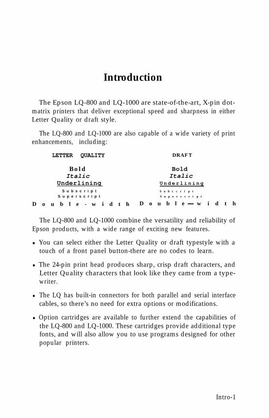
The Epson LQ-800 and LQ-1000 are state-of-the-art, X-pin dot-matrix printers that deliver exceptional speed and sharpness in eitherLetter Quality or draft style.
The LQ-800 and LQ-1000 are also capable of a wide variety of printenhancements, including:
LETTER QUALITY D R A F T
Bold BoldItalic Italic
Underlining U n d e r l i n i n g
S u b s c r i p t S u b s c r i p t
S u p e r s c r i p t S u p e r s c r i p t
D o u b l e - w i d t h D o u b l e w i d t h
The LQ-800 and LQ-1000 combine the versatility and reliability ofEpson products, with a wide range of exciting new features.
l You can select either the Letter Quality or draft typestyle with atouch of a front panel button-there are no codes to learn.
l The 24-pin print head produces sharp, crisp draft characters, andLetter Quality characters that look like they came from a type-writer.
l The LQ has built-in connectors for both parallel and serial interfacecables, so there’s no need for extra options or modifications.
l Option cartridges are available to further extend the capabilities ofthe LQ-800 and LQ-1000. These cartridges provide additional typefonts, and will also allow you to use programs designed for otherpopular printers.
Intro-1
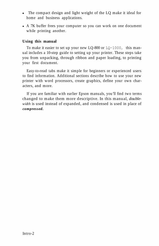
l The compact design and light weight of the LQ make it ideal forhome and business applications.
l A 7K buffer frees your computer so you can work on one documentwhile printing another.
Using this manual
To make it easier to set up your new LQ-800 or LQ-1000, this man-ual includes a 10-step guide to setting up your printer. These steps takeyou from unpacking, through ribbon and paper loading, to printingyour first document.
Easy-to-read tabs make it simple for beginners or experienced usersto find information. Additional sections describe how to use your newprinter with word processors, create graphics, define your own char-acters, and more.
If you are familiar with earlier Epson manuals, you’ll find two termschanged to make them more descriptive. In this manual, double-width is used instead of expanded, and condensed is used in place ofcompressed.
Intro-2
Chapter 1Setting Up Your LQ Printer
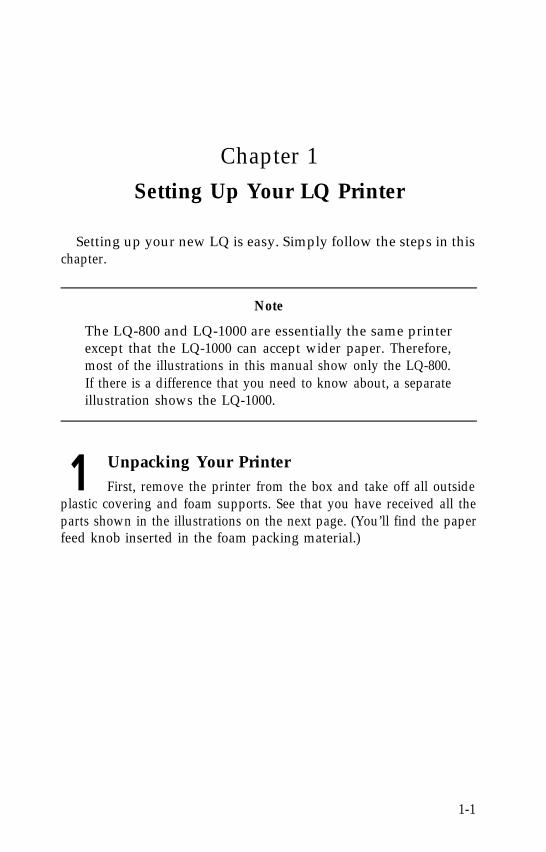
Setting up your new LQ is easy. Simply follow the steps in thischapter.
Note
The LQ-800 and LQ-1000 are essentially the same printerexcept that the LQ-1000 can accept wider paper. Therefore,most of the illustrations in this manual show only the LQ-800.If there is a difference that you need to know about, a separateillustration shows the LQ-1000.
1 Unpacking Your PrinterFirst, remove the printer from the box and take off all outside
plastic covering and foam supports. See that you have received all theparts shown in the illustrations on the next page. (You’ll find the paperfeed knob inserted in the foam packing material.)
1-1
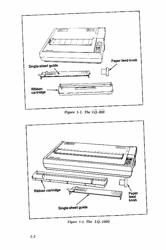
Figure 1-1. The LQ-800
Figure 1-2. The LQ-1000
1-2
Remove the tape that holds the dust cover in place during shippingand take the cover off the printer. Simply tilt the dust cover up and liftit off the printer.
WARNING
The print head is protected by two plastic bumpers during shipping.Both of these bumpers must be removed before turning on the printer.Remove the long bumper to the right of the print head first, then movethe print head to the center of the LQ and remove the small bumperon the left side of the print head.
There is a clear plastic overlay on the control panel to protect itfrom scratching and discoloration. It’s up to you whether you removethe overlay or leave it on.
Installing the paper feed knob
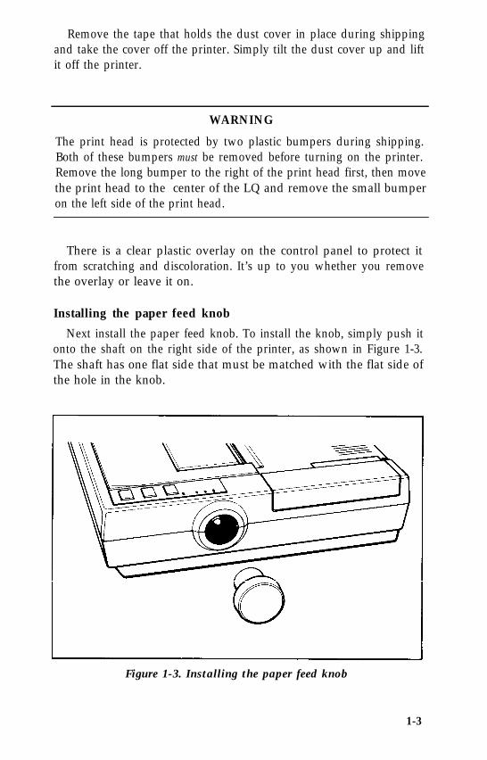
Next install the paper feed knob. To install the knob, simply push itonto the shaft on the right side of the printer, as shown in Figure 1-3.The shaft has one flat side that must be matched with the flat side ofthe hole in the knob.
Figure 1-3. Installing the paper feed knob
1-3
Now that you’ve installed the paper feed knob, use it to remove thesheet of paper wrapped around the printer’s platen (the black roller).
2 Selecting the Right LocationThe most important consideration in choosing a location for
your printer is that it be close enough to connect a cable to your com-puter. But also keep the following tips in mind:
l Place the printer or printer stand on a solid and level foundation.Avoid setting it on carpet, chairs, or unstable surfaces.
l Use a grounded outlet-one that has three holes to match the powerplug on the printer. Don’t use an adapter plug.
l Avoid using electrical outlets that are controlled by wall switches-if you accidentally turn off a switch, you could wipe out valuableinformation and stop your printing.
l Keep your printer and computer away from base units for cordlesstelephones.
l Avoid using an outlet on the same circuit breaker with large electri-cal machines or appliances that might disrupt the flow of power toyour printer.
l Protect your printer from direct sunlight, and keep it away fromexcessive heat, moisture, and dust. Make sure it’s not too close to aheater or any other heat source.
1-4
3 Installing the RibbonWith the dust cover removed, you have easy access to the
printer for ribbon installation and paper loading. The next time youinstall a ribbon or load paper, you can leave the cover on.
Now you’re ready to install the ribbon.
1. Manually move the print head to the middle of the platen.
WARNING
The power must be OFF when moving the print head. Movingthe print head when the power is ON may damage yourprinter. If you’ve been using your printer just before changingthe ribbon cartridge, be careful not to touch the print headbecause it becomes hot during use.
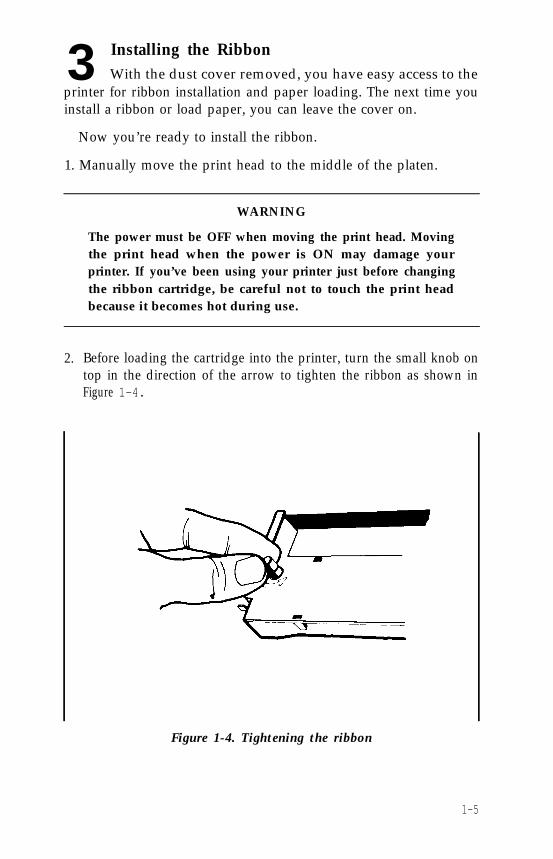
2. Before loading the cartridge into the printer, turn the small knob ontop in the direction of the arrow to tighten the ribbon as shown inFigure 1-4.
Figure 1-4. Tightening the ribbon
1-5
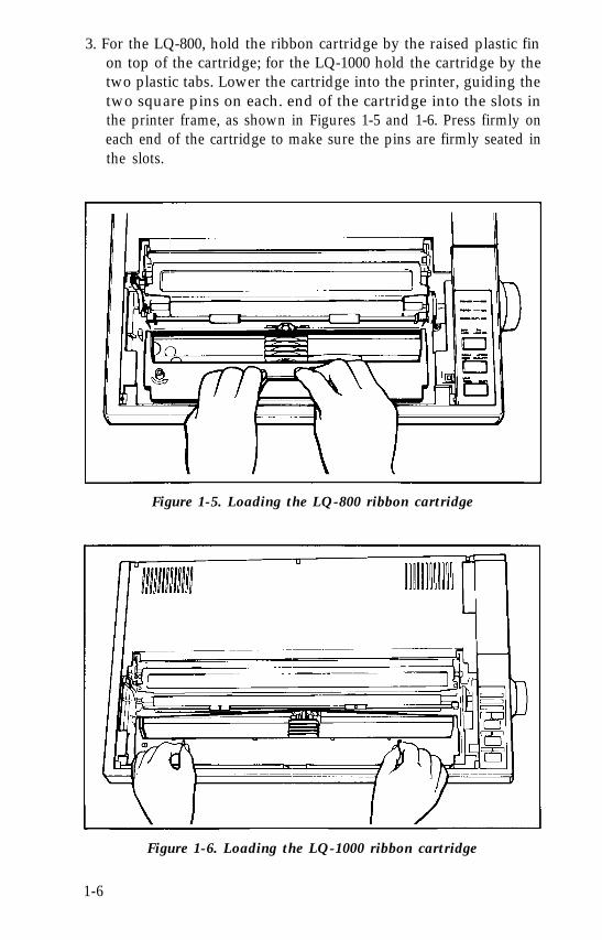
3. For the LQ-800, hold the ribbon cartridge by the raised plastic finon top of the cartridge; for the LQ-1000 hold the cartridge by thetwo plastic tabs. Lower the cartridge into the printer, guiding thetwo square pins on each. end of the cartridge into the slots inthe printer frame, as shown in Figures 1-5 and 1-6. Press firmly oneach end of the cartridge to make sure the pins are firmly seated inthe slots.
Figure 1-5. Loading the LQ-800 ribbon cartridge
Figure 1-6. Loading the LQ-1000 ribbon cartridge
1-6
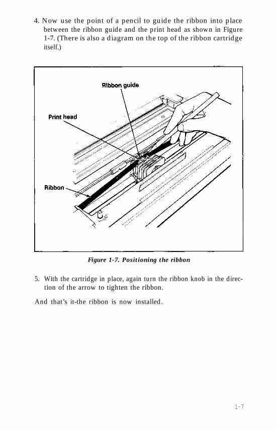
4. Now use the point of a pencil to guide the ribbon into placebetween the ribbon guide and the print head as shown in Figure1-7. (There is also a diagram on the top of the ribbon cartridgeitself.)
Figure 1-7. Positioning the ribbon
5. With the cartridge in place, again turn the ribbon knob in the direc-tion of the arrow to tighten the ribbon.
And that’s it-the ribbon is now installed.
1-7
Replacing the ribbon. . .
When buying new ribbon cartridges for the LQ-800 or 1000, be sureyou get a ribbon specifically for the LQ-800 or 1000. Ribbon cartridgesfor other Epson printers, such as the FX series, may closely resemblean LQ ribbon, but their use can damage the LQ print head. Also,ribbon cartridges for the LQ-1500 will not fit the LQ-800 or 1000, andthe Epson ribbon replacement pack #8758 should not be used as areplacement ribbon.
The LQ uses a continuous-loop, inked fabric ribbon. When yourprinting becomes too light, replace the ribbon with a fresh cartridge.To replace the ribbon, just pull up on the raised fin on top of theLQ-800 cartridge, or the two plastic tabs on the LQ-1000 and lift thecartridge out of the printer. To install a new ribbon, follow the preced-ing steps.
4 Loading Single-Sheet PaperWhen you receive your LQ, it is set up to print on single sheets
of paper. Even if you have purchased one of the optional paper feed-ing systems (the cut sheet feeder or the tractor unit), you should firstcomplete the remaining setup steps before installing either of theoptional systems.
It is much easier to run the self test (Step 8) and to connect the LQ toyour computer (Step 9) before you install an optional system. Aftercompleting the setup steps, see Chapter 2 for installing the cut sheetfeeder, or Chapter 3 for installing the tractor unit.
Installing the single-sheet guide
Now install the single-sheet guide. It helps you feed individualsheets of paper into the LQ.
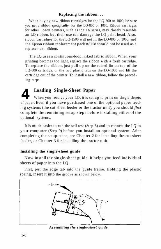
First, put the edge tab into the guide frame. Holding the plasticspring, insert it into the groove as shown below.
Assembling the single-sheet guide
1-8
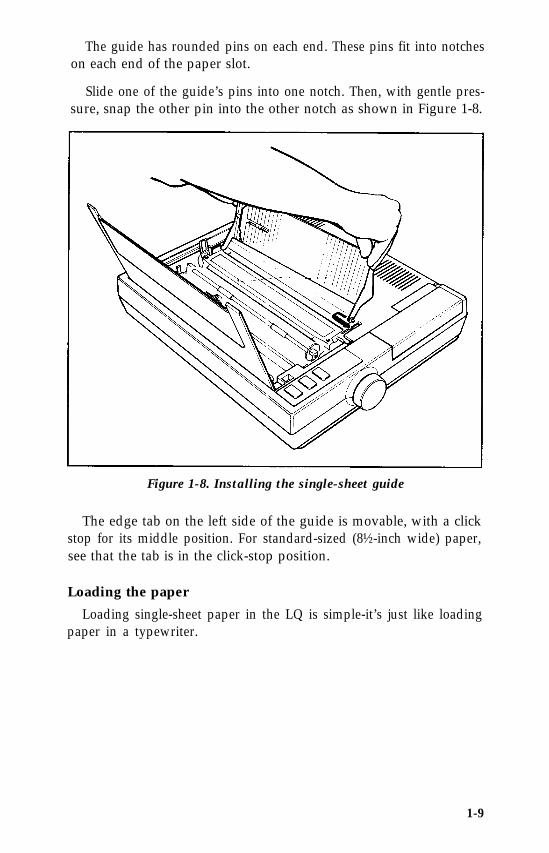
The guide has rounded pins on each end. These pins fit into notcheson each end of the paper slot.
Slide one of the guide’s pins into one notch. Then, with gentle pres-sure, snap the other pin into the other notch as shown in Figure 1-8.
Figure 1-8. Installing the single-sheet guide
The edge tab on the left side of the guide is movable, with a clickstop for its middle position. For standard-sized (8½-inch wide) paper,see that the tab is in the click-stop position.
Loading the paper
Loading single-sheet paper in the LQ is simple-it’s just like loadingpaper in a typewriter.
1-9
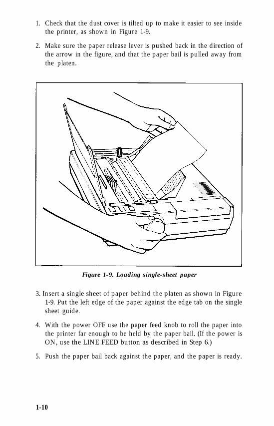
1. Check that the dust cover is tilted up to make it easier to see insidethe printer, as shown in Figure 1-9.
2. Make sure the paper release lever is pushed back in the direction ofthe arrow in the figure, and that the paper bail is pulled away fromthe platen.
Figure 1-9. Loading single-sheet paper
3. Insert a single sheet of paper behind the platen as shown in Figure1-9. Put the left edge of the paper against the edge tab on the singlesheet guide.
4. With the power OFF use the paper feed knob to roll the paper intothe printer far enough to be held by the paper bail. (If the power isON, use the LINE FEED button as described in Step 6.)
5. Push the paper bail back against the paper, and the paper is ready.
1-10
Caution
Never use the manual paper feed knob while the power is ONbecause you can damage the paper feed motor. Always use the LINE FEED or FORM FEED button. You will also find thatthe paper feed knob turns easily when the power is OFF, but isdifficult to turn while the power is ON.
When loading single-sheet paper, you may find that the LQ finishespages at different places than your word processor or applicationsprogram does.
To ensure that your word processor and the LQ finish pages at thesame point:
1. Print out a page on the LQ. Check that the LQ and your wordprocessor have the same page length. If they differ, note how manylines they differ by. For example, if your word processor is set up toprint 55 lines, but the LQ only prints 53 lines before ejecting thepage, there is a difference of two lines.
2. You now have three choices:
a) Compensate for the two-line difference when rolling the paperinto the printer.
b) Use the installation procedure on your word processor tochange the default page length.
c) Use commands in your word processing program to alter thepage or margin lengths in each file to accommodate the LQ’spage length.
3. Once you’ve established the best settings, always load the paper sothat your printer starts at the same place on each page. For exam-ple, you may find that when you roll the paper one inch above theprint head, the page finishes where you want it to-then each timeyou load paper, load it the same way.
With single-sheet paper, the key to consistent page formatting is toestablish the settings that work best for you, then position the paper inthe same place every time.
1-11
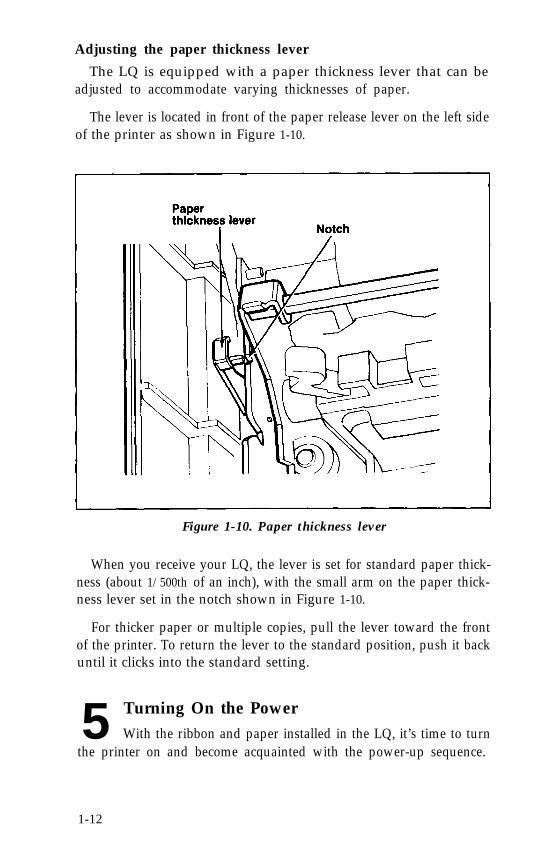
Adjusting the paper thickness lever
The LQ is equipped with a paper thickness lever that can beadjusted to accommodate varying thicknesses of paper.
The lever is located in front of the paper release lever on the left sideof the printer as shown in Figure 1-10.
Figure 1-10. Paper thickness lever
When you receive your LQ, the lever is set for standard paper thick-ness (about 1/500th of an inch), with the small arm on the paper thick-ness lever set in the notch shown in Figure 1-10.
For thicker paper or multiple copies, pull the lever toward the frontof the printer. To return the lever to the standard position, push it backuntil it clicks into the standard setting.
5 Turning On the PowerWith the ribbon and paper installed in the LQ, it’s time to turn
the printer on and become acquainted with the power-up sequence.
1-12
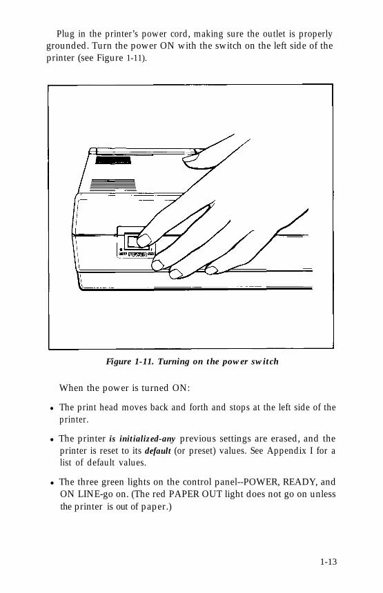
Plug in the printer’s power cord, making sure the outlet is properlygrounded. Turn the power ON with the switch on the left side of theprinter (see Figure 1-11).
Figure 1-11. Turning on the power switch
When the power is turned ON:
l The print head moves back and forth and stops at the left side of theprinter.
l The printer is initialized-any previous settings are erased, and theprinter is reset to its default (or preset) values. See Appendix I for alist of default values.
l The three green lights on the control panel--POWER, READY, andON LINE-go on. (The red PAPER OUT light does not go on unlessthe printer is out of paper.)
1-13
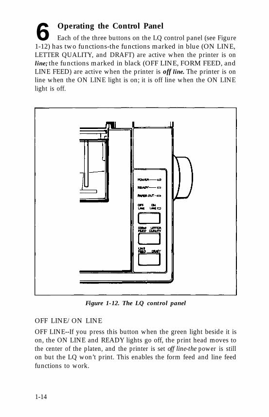
6 Operating the Control PanelEach of the three buttons on the LQ control panel (see Figure
1-12) has two functions-the functions marked in blue (ON LINE,LETTER QUALITY, and DRAFT) are active when the printer is online; the functions marked in black (OFF LINE, FORM FEED, andLINE FEED) are active when the printer is off line. The printer is online when the ON LINE light is on; it is off line when the ON LINElight is off.
Figure 1-12. The LQ control panel
OFF LINE/ON LINE
OFF LINE--If you press this button when the green light beside it ison, the ON LINE and READY lights go off, the print head moves tothe center of the platen, and the printer is set off line-the power is stillon but the LQ won’t print. This enables the form feed and line feedfunctions to work.
1-14
ON LINE-The green ON LINE light indicates that the printer is online and ready to receive data. When the LQ is on line, you can selecteither the Letter Quality or draft mode.
FORM FEED/LETTER QUALITY
FORM FEED-Pressing this button advances the paper to the top ofthe next page if you’re using continuous-feed paper (see Chapter 3,“Installing the Tractor Unit”). If you’re using single-sheet paper, it fullyejects one sheet. The form feed function works only when the printeris off line.
LETTER QUALITY-Pressing this button selects the Letter Qualitytypestyle (for more information on Letter Quality, see Step 7). Theprinter beeps twice to acknowledge the Letter Quality selection. Youcan select the Letter Quality typestyle with this button only when theprinter is on line.
LINE FEED/DRAFT
LINE FEED-Pressing this button advances the paper one line at atime, either while you’re loading paper, or when you’re adjustingwhere you want printing to begin. If you hold this button down, thepaper advances continuously. The line feed function works only whenthe printer is off line.
DRAFT-Pressing this button selects the draft typestyle. The printerbeeps once to acknowledge the draft selection. The draft functionworks only when the printer is on line.
Note
Use the LETTER QUALITY or DRAFT buttons before youtell the computer to print. Do not use them while the LQ isprinting.
1-15
7 Selecting the Letter Quality or Draft ModeWhen you receive your LQ, it is preset to print in the Letter
Quality mode. As shown in the sample below, the Letter Qualitycharacters are fully formed and are ideal for formal correspondence orother presentation-quality work.
For those times when you need only a rough draft, the LQ also has a
draft mode, also shown below. In draft mode, the LQ prints morequickly, because fewer dots are used to form each letter.
This is the Letter Quality style
T h i s i s t h e d r a f t S t y l e
The LQ gives you three ways to select either the Letter Quality ordraft mode.
l Control panel-You can choose between the Letter Quality anddraft modes with the appropriate button on the control panel.
l DIP switch-A switch on the back of the printer selects either LetterQuality or draft as the default typestyle (the style in effect when youturn the power on). See Appendix A for details.
l Software command-You can also switch between the Letter Qual-ity and draft modes by sending a command to the printer asexplained in Chapter 5.
These three choices allow you to tailor the LQ to your printingneeds. If you find you use the Letter Quality mode most of the time,you can leave the settings just as they are. If you print in draft modemore than Letter Quality, just reset the DIP switch as outlined inAppendix A. But no matter what you choose, you can always use thebuttons on the control panel to switch between the two styles.
8 Running the Self TestThe LQ has a built-in self test function that automatically
prints out all of the characters in the selected character set-eitherLetter Quality or draft.
Before running the self test, make sure that paper is loaded in theprinter and that the power is turned OFF. If you have an LQ-1000, besure to use 14-inch-wide paper to avoid printing on the platen.
1-16
To run the self test in the Letter Quality mode, hold down theLETTER QUALITY button while you turn the power switch ON. Torun the test in the draft mode, hold down the DRAFT button whileturning the power ON. The self test then takes over.
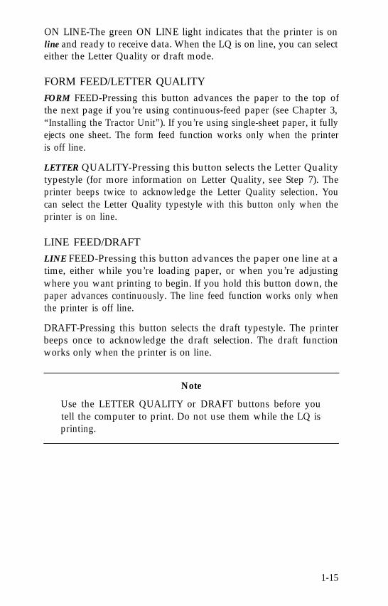
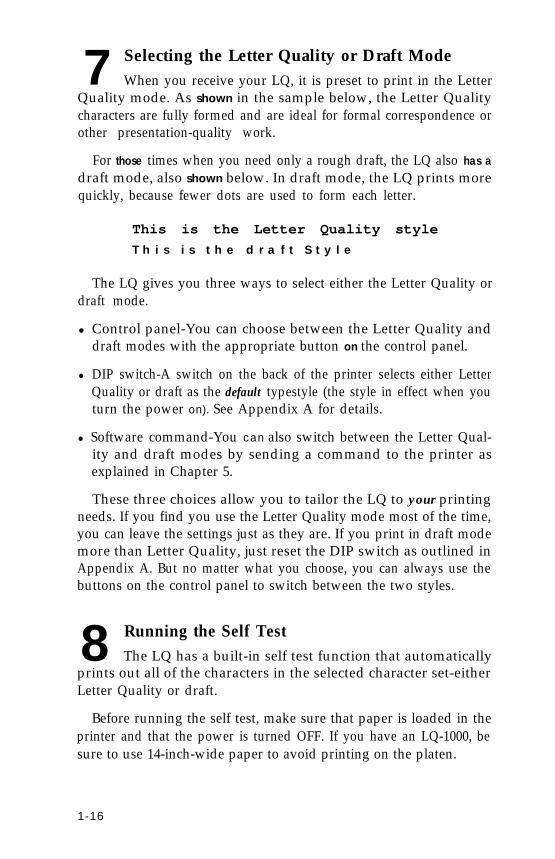
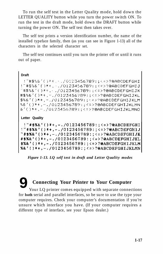
The self test prints a version identification number, the name of theinstalled typeface family, then (as you can see in Figure 1-13) all of thecharacters in the selected character set.
The self test continues until you turn the printer off or until it runsout of paper.
Draft
Letter Quality
Figure 1-13. LQ self test in draft and Letter Quality modes
9 Connecting Your Printer to Your Computer Your LQ printer comes equipped with separate connectionsfor both serial and parallel interfaces, so be sure to use the type yourcomputer requires. Check your computer’s documentation if you’reunsure which interface you have. (If your computer requires adifferent type of interface, see your Epson dealer.)
1-17
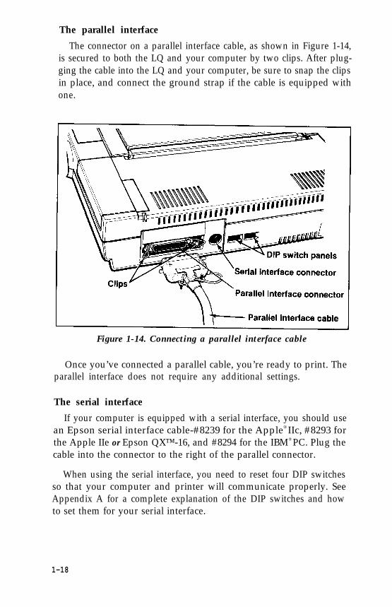
The parallel interface
The connector on a parallel interface cable, as shown in Figure 1-14,is secured to both the LQ and your computer by two clips. After plug-ging the cable into the LQ and your computer, be sure to snap the clipsin place, and connect the ground strap if the cable is equipped withone.
Figure 1-14. Connecting a parallel interface cable
Once you’ve connected a parallel cable, you’re ready to print. Theparallel interface does not require any additional settings.
The serial interface
If your computer is equipped with a serial interface, you should usean Epson serial interface cable-#8239 for the Apple® IIc, #8293 forthe Apple IIe or Epson QX™-16, and #8294 for the IBM® PC. Plug thecable into the connector to the right of the parallel connector.
When using the serial interface, you need to reset four DIP switchesso that your computer and printer will communicate properly. SeeAppendix A for a complete explanation of the DIP switches and howto set them for your serial interface.
1-18
10 Printing Your First DocumentNow that you’ve completed the basic setup and operat-
ing steps, your LQ is ready to print. The following chapter explainshow to set up your word processor to work with the LQ.
Additional chapters and appendixes cover programming, controlcodes and ESCape sequences, technical specifications and mainte-nance .
If you have any difficulty printing your first document, check thefollowing list to make sure you’ve completed all the setup steps.
q Did you remove the plastic tab that holds the print head in place?
q Is the power source (power strip, etc.) turned ON?
q Is the ribbon properly installed? Make sure the ribbon is in front ofthe print head, not riding above it.
q Have you loaded the paper correctly? (Read Chapter 2 or 3 if youare using the optional cut sheet feeder or tractor unit.)
q Are the green POWER, ON LINE, and READY lights on the con-trol panel ON? If not, press the ON LINE button to place the LQon line. If the red PAPER OUT light is ON, check that you’veloaded the paper correctly.
q Were you able to successfully run the self test in Step 8? If not,check the DIP switch settings and try again.
q Is your printer properly connected to your computer? Are youusing the correct interface (serial or parallel)? If you’re using aserial interface, have you set the DIP switches accordingly?
If you’re still having trouble printing, read the troubleshooting sec-tion in Appendix D.
1-19
Chapter 2The Cut Sheet Feeder
The cut sheet feeder automatically loads single sheets of paper intothe LQ, allowing you to print on letterhead, bond, or individualforms.
Installing the Cut Sheet Feeder1. Make sure the power is OFF.
2. Set DIP switch 1-8 on the back of the printer to the ON positionand DIP switch 1-7 to the OFF position to select the cut sheetfeeder. See Appendix A for information on resetting the DIPswitches.
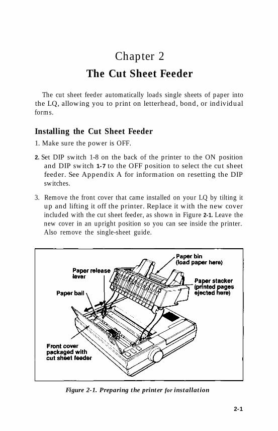
3. Remove the front cover that came installed on your LQ by tilting itup and lifting it off the printer. Replace it with the new coverincluded with the cut sheet feeder, as shown in Figure 2-1. Leave thenew cover in an upright position so you can see inside the printer.Also remove the single-sheet guide.
Figure 2-1. Preparing the printer for installation
2-1
4. Make sure the paper release lever is pushed back as shown in Fig-ure 2-1. If this lever is not pushed back, the cut sheet feeder will notfit or operate properly.
5. Pull the paper bail away from the platen (the black roller) as shownin Figure 2-1. The paper bail should remain in this position when-ever the cut sheet feeder is installed.
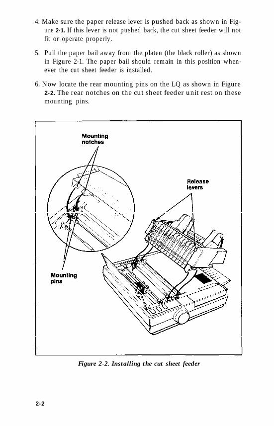
6. Now locate the rear mounting pins on the LQ as shown in Figure2-2. The rear notches on the cut sheet feeder unit rest on thesemounting pins.
Figure 2-2. Installing the cut sheet feeder
2-2
7. Hold the cut sheet feeder assembly in two hands, and press the twocut sheet feeder release levers shown in Figure 2-1.
8. Now stand directly over the printer, look through the top of the cutsheet feeder, and guide the rear notches on the cut sheet feeder ontothe rear mounting pins on the printer.
9. Tilt the cut sheet feeder forward until the front latches of the cutsheet feeder engage the front mounting pins on the printer. Releasethe levers and the cut sheet feeder locks in place.
Note
When the cut sheet feeder is properly installed, it is possible totilt it forward slightly, but you cannot remove it from theprinter without pressing the release levers. If you can removethe cut sheet feeder by simply lifting it off the LQ, reread theinstallation instructions, paying special attention to settingthe rear notches of the feeder on the rear mounting pins of theprinter.
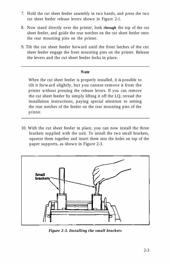
10. With the cut sheet feeder in place, you can now install the threebrackets supplied with the unit. To install the two small brackets,squeeze them together and insert them into the holes on top of thepaper supports, as shown in Figure 2-3.
Figure 2-3. Installing the small brackets
2-3
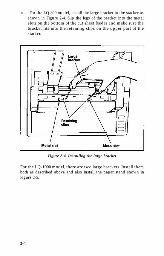
11. For the LQ-800 model, install the large bracket in the stacker asshown in Figure 2-4. Slip the legs of the bracket into the metalslots on the bottom of the cut sheet feeder and make sure thebracket fits into the retaining clips on the upper part of thestacker.
Figure 2-4. Installing the large bracket
For the LQ-1000 model, there are two large brackets. Install themboth as described above and also install the paper stand shown inFigure 2-5.
2-4
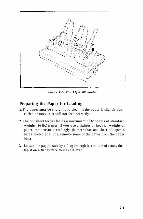
Figure 2-5. The LQ-1000 model
Preparing the Paper for Loading1. The paper must be straight and clean. If the paper is slightly bent,
curled or uneven, it will not feed correctly.
2. The cut sheet feeder holds a maximum of 60 sheets of standardweight (20 lb.) paper. If you use a lighter or heavier weight ofpaper, compensate accordingly. (If more than one sheet of paper isbeing loaded at a time, remove some of the paper from the paperbin.)
3. Loosen the paper stack by rifling through it a couple of times, thentap it on a flat surface to make it even.
2-5
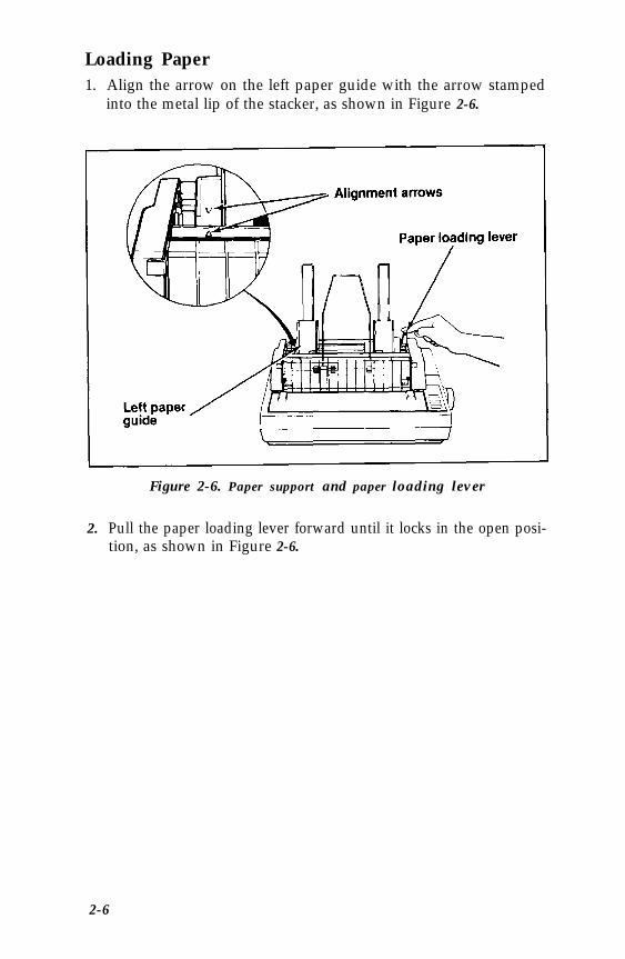
Loading Paper1. Align the arrow on the left paper guide with the arrow stamped
into the metal lip of the stacker, as shown in Figure 2-6.
Figure 2-6. Paper support and paper loading lever
2. Pull the paper loading lever forward until it locks in the open posi-tion, as shown in Figure 2-6.
2-6
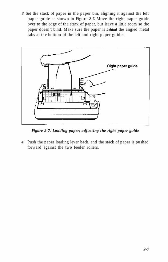
3. Set the stack of paper in the paper bin, aligning it against the leftpaper guide as shown in Figure 2-7. Move the right paper guideover to the edge of the stack of paper, but leave a little room so thepaper doesn’t bind. Make sure the paper is behind the angled metaltabs at the bottom of the left and right paper guides.
Figure 2-7. Loading paper; adjusting the right paper guide
4. Push the paper loading lever back, and the stack of paper is pushedforward against the two feeder rollers.
2-7
setting up your word processor for a cut sheet feeder. . .If you‘ve never used a cut sheet feeder before, you may have to set
up your word processor accordingly.
When the cut sheet feeder positions the paper for printing, it auto-matically leaves a one-inch margin at the top of a page. If you’ve beenprinting with continuous-feed paper, you11 need to adjust the settingson your word processor so that the pages print the same with the cutsheet feeder.
There are three settings you’ll probably need to change: PageLength, Top Margin, and bottom Margin. Most word processorshave preset (or default) settings that are in effect each time you use theprogram. Check the program’s documentation to find these settings,and how to change them.
The following is an example of a typical conversion.
To maintain 55 printed lines per page:
Continuous-feed Cut sheetsettings feeder settings
Change Page Length from 66 to 6 1
Change Top Margin from 3 (default) to 0
Change Bottom Margin from 8 (default) to 6
Many word processors give you two choices in changing these set-tings: 1) You can change the settings in each individual file you print,or; 2) You can change the program’s default settings so that every timeyou use the program, these new settings are in effect.
If your program has additional features, such as headers and foot-notes, you will have to compensate accordingly. (For example, manyprograms include the header as part of the top margin. If you set thetop margin to 0, you11 lose the header.)
With a little bit of experimenting, you’ll find the best equivalentsettings to use.
2-8
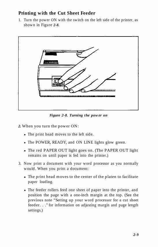
Printing with the Cut Sheet Feeder1. Turn the power ON with the switch on the left side of the printer, as
shown in Figure 2-8.
Figure 2-8. Turning the power on
2. When you turn the power ON:
l The print head moves to the left side.
l The POWER, READY, and ON LINE lights glow green.
l The red PAPER OUT light goes on. (The PAPER OUT lightremains on until paper is fed into the printer.)
3. Now print a document with your word processor as you normallywould. When you print a document:
l The print head moves to the center of the platen to facilitatepaper loading.
l The feeder rollers feed one sheet of paper into the printer, andposition the page with a one-inch margin at the top. (See theprevious note “Setting up your word processor for a cut sheetfeeder. . ." for information on adjusting margin and page lengthsettings.)
2-9
l The red PAPER OUT light goes out while there’s paper in theprinter.
l Printing begins.
When the LQ finishes printing a document, you have three options.
If you wish to continue printing-You can print another document asyou normally would; the cut sheet feeder ejects the last page from theprevious job, then loads and prints the new document.
If you want to fully eject the last page of a document-First take theLQ off line by pressing the ON LINE button (the green ON LINE lightgoes out). Press the FORM FEED button to eject the last page into thepaper stacker, and a new sheet is automatically loaded.
If you’re finished printing-Remove the unused paper from the bin,take the printer off line, then use the FORM FEED button to eject thelast sheet of paper. (If you press FORM FEED without removing theremaining paper from the bin, another sheet is loaded.) You can alsoshut the power OFF, then use the manual paper feed knob to roll theremaining sheet out of the printer.
Caution
When the power is ON, you should use only the FORM FEEDor LINE FEED button to eject paper from the cut sheet feeder.If you use the manual paper feed knob, the power shouldalways be OFF to prevent damage to the paper feed motor.
Removing the Cut Sheet FeederTo remove the cut sheet feeder:
1. Turn the power for the printer OFF.
2. Remove all the unused paper from the bin, and any printed sheetsfrom the stacker.
3. If a sheet of paper is still loaded in the printer, use the manual paperfeed knob to remove it.
2-10
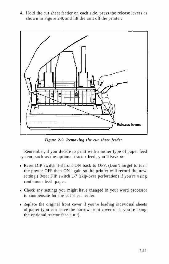
4. Hold the cut sheet feeder on each side, press the release levers asshown in Figure 2-9, and lift the unit off the printer.
Figure 2-9. Removing the cut sheet feeder
Remember, if you decide to print with another type of paper feedsystem, such as the optional tractor feed, you’ll have to:
l Reset DIP switch 1-8 from ON back to OFF. (Don’t forget to turnthe power OFF then ON again so the printer will record the newsetting.) Reset DIP switch 1-7 (skip-over perforation) if you’re usingcontinuous-feed paper.
l Check any settings you might have changed in your word processorto compensate for the cut sheet feeder.
l Replace the original front cover if you’re loading individual sheetsof paper (you can leave the narrow front cover on if you’re usingthe optional tractor feed unit).
2-11
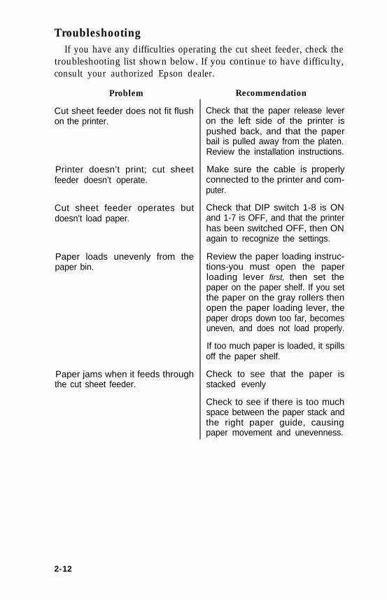
TroubleshootingIf you have any difficulties operating the cut sheet feeder, check the
troubleshooting list shown below. If you continue to have difficulty,consult your authorized Epson dealer.
Problem
Cut sheet feeder does not fit flushon the printer.
Printer doesn’t print; cut sheetfeeder doesn’t operate.
Cut sheet feeder operates butdoesn’t load paper.
Paper loads unevenly from thepaper bin.
Paper jams when it feeds throughthe cut sheet feeder.
Recommendation
Check that the paper release leveron the left side of the printer ispushed back, and that the paperbail is pulled away from the platen.Review the installation instructions.
Make sure the cable is properlyconnected to the printer and com-puter.
Check that DIP switch 1-8 is ONand 1-7 is OFF, and that the printerhas been switched OFF, then ONagain to recognize the settings.
Review the paper loading instruc-tions-you must open the paperloading lever first, then set thepaper on the paper shelf. If you setthe paper on the gray rollers thenopen the paper loading lever, thepaper drops down too far, becomesuneven, and does not load properly.
If too much paper is loaded, it spillsoff the paper shelf.
Check to see that the paper isstacked evenly
Check to see if there is too muchspace between the paper stack andthe right paper guide, causingpaper movement and unevenness.
2-12
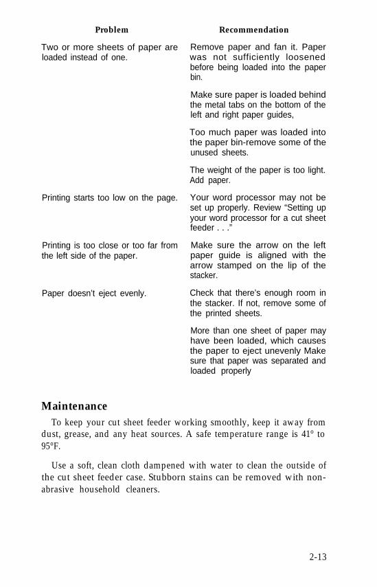
Problem
Two or more sheets of paper areloaded instead of one.
Printing starts too low on the page.
Printing is too close or too far fromthe left side of the paper.
Paper doesn’t eject evenly.
Maintenance
Recommendation
Remove paper and fan it. Paperwas not sufficiently loosenedbefore being loaded into the paperbin.
Make sure paper is loaded behindthe metal tabs on the bottom of theleft and right paper guides,
Too much paper was loaded intothe paper bin-remove some of theunused sheets.
The weight of the paper is too light.Add paper.
Your word processor may not beset up properly. Review “Setting upyour word processor for a cut sheetfeeder . . .”
Make sure the arrow on the leftpaper guide is aligned with thearrow stamped on the lip of thestacker.
Check that there’s enough room inthe stacker. If not, remove some ofthe printed sheets.
More than one sheet of paper mayhave been loaded, which causesthe paper to eject unevenly Makesure that paper was separated andloaded properly
To keep your cut sheet feeder working smoothly, keep it away fromdust, grease, and any heat sources. A safe temperature range is 41° to95°F.
Use a soft, clean cloth dampened with water to clean the outside ofthe cut sheet feeder case. Stubborn stains can be removed with non-abrasive household cleaners.
2-13
Periodically, the inside of the cut sheet feeder should be cleaned toget rid of dust and paper lint. First, turn the power OFF and removethe cut sheet feeder from the printer. Then use a soft brush to clean theinside areas. Make sure the gray rollers are kept free of dust so that thepaper feeds evenly.
If you have any problems, contact your authorized Epson dealer.
2-14
Chapter 3The Tractor Unit
The tractor unit for the LQ is easy to install and use. Before youbegin the installation, make sure you have received the following:l The tractor unit
l The smoke-colored tractor coverl The narrow front lid
l The paper separator
l The paper shelf
Setting Up the LQ for Continuous-feed PaperBefore installing the tractor unit, you should set up your LQ so that
continuous-feed paper can flow freely in and out of the printer.
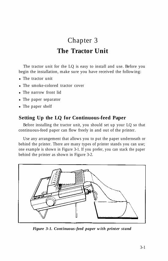
Use any arrangement that allows you to put the paper underneath orbehind the printer. There are many types of printer stands you can use;one example is shown in Figure 3-1. If you prefer, you can stack the paperbehind the printer as shown in Figure 3-2.
Figure 3-1. Continuous-feed paper with printer stand
3-1
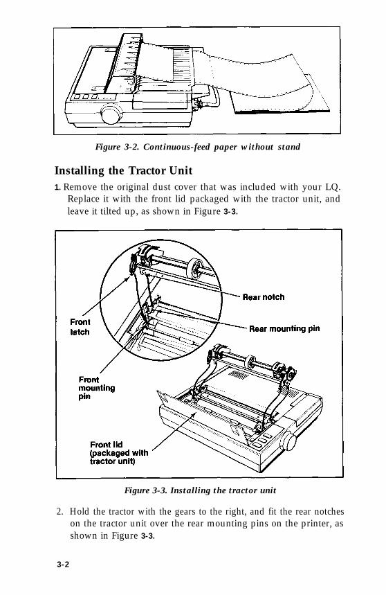
Figure 3-2. Continuous-feed paper without stand
Installing the Tractor Unit1. Remove the original dust cover that was included with your LQ.
Replace it with the front lid packaged with the tractor unit, andleave it tilted up, as shown in Figure 3-3.
Figure 3-3. Installing the tractor unit
2. Hold the tractor with the gears to the right, and fit the rear notcheson the tractor unit over the rear mounting pins on the printer, asshown in Figure 3-3.
3-2
3. Tilt the tractor unit toward you until the front latches click in placeover the front mounting pins on the printer.
Loading PaperTo load continuous-feed paper, follow these instructions:
1. Make sure that the printer is turned OFF.
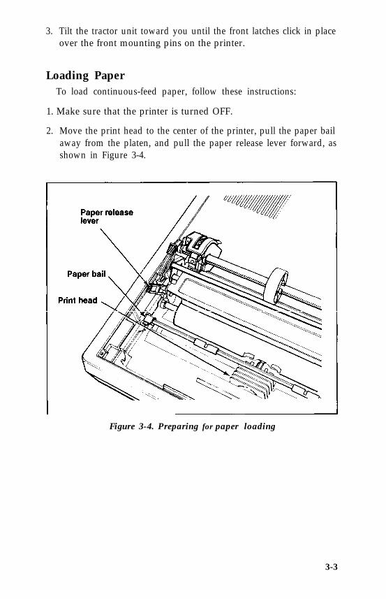
2. Move the print head to the center of the printer, pull the paper bailaway from the platen, and pull the paper release lever forward, asshown in Figure 3-4.
Figure 3-4. Preparing for paper loading
3-3
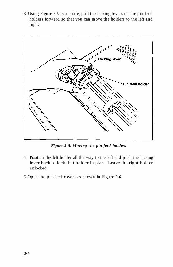
3. Using Figure 3-5 as a guide, pull the locking levers on the pin-feedholders forward so that you can move the holders to the left andright.
Figure 3-5. Moving the pin-feed holders
4. Position the left holder all the way to the left and push the lockinglever back to lock that holder in place. Leave the right holderunlocked.
5. Open the pin-feed covers as shown in Figure 3-6.
3-4
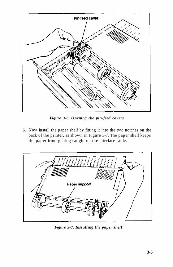
Figure 3-6. Opening the pin-feed covers
6. Now install the paper shelf by fitting it into the two notches on theback of the printer, as shown in Figure 3-7. The paper shelf keepsthe paper from getting caught on the interface cable.
Figure 3-7. Installing the paper shelf
3-5
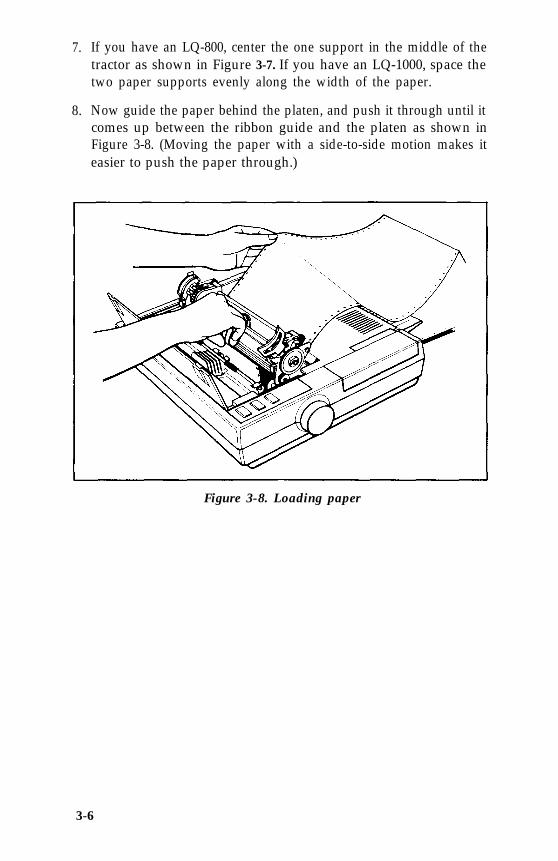
7. If you have an LQ-800, center the one support in the middle of thetractor as shown in Figure 3-7. If you have an LQ-1000, space thetwo paper supports evenly along the width of the paper.
8. Now guide the paper behind the platen, and push it through until itcomes up between the ribbon guide and the platen as shown inFigure 3-8. (Moving the paper with a side-to-side motion makes iteasier to push the paper through.)
Figure 3-8. Loading paper
3-6
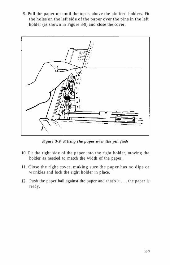
9. Pull the paper up until the top is above the pin-feed holders. Fitthe holes on the left side of the paper over the pins in the leftholder (as shown in Figure 3-9) and close the cover.
Figure 3-9. Fitting the paper over the pin feeds
10. Fit the right side of the paper into the right holder, moving theholder as needed to match the width of the paper.
11. Close the right cover, making sure the paper has no dips orwrinkles and lock the right holder in place.
12. Push the paper bail against the paper and that’s it . . . the paper isready.
3-7
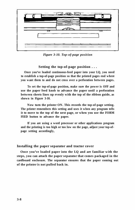
Figure 3-10. Top-of-page position
Setting the top-of-page position . . .Once you‘ve loaded continuous-feed paper into your LQ, you need
to establish a top-of-page position so that the printed pages end whereyou want them to and do not cross over a perforation between pages.
To set the top-of-page position, make sure the power is OFF anduse the paper feed knob to advance the paper until a perforationbetween sheets lines up evenly with the top of the ribbon guide, asshown in Figure 3-10.
Now turn the printer ON. This records the top-of-page setting.The printer remembers this setting and uses it when any program tellsit to move to the top of the next page, or when you use the FORMFEED button to advance the paper.
If you are using a word processor or other applications programand the printing is too high or too low on the page, adjust your top-of-page setting accordingly,
Installing the paper separator and tractor cover
Once you’ve loaded paper into the LQ and are familiar with thesteps, you can attach the paper separator that comes packaged in thecardboard enclosure. The separator ensures that the paper coming outof the printer is not pulled back in.
3-8
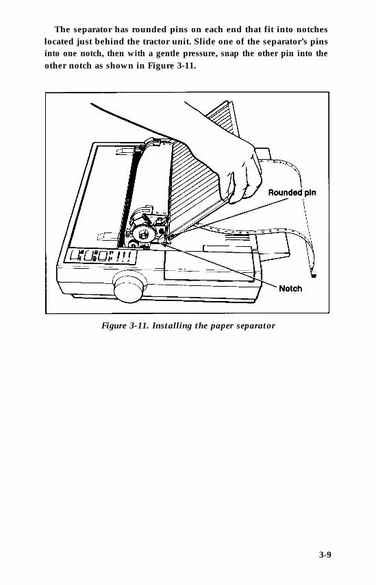
The separator has rounded pins on each end that fit into notcheslocated just behind the tractor unit. Slide one of the separator’s pinsinto one notch, then with a gentle pressure, snap the other pin into theother notch as shown in Figure 3-11.
Figure 3-11. Installing the paper separator
3-9
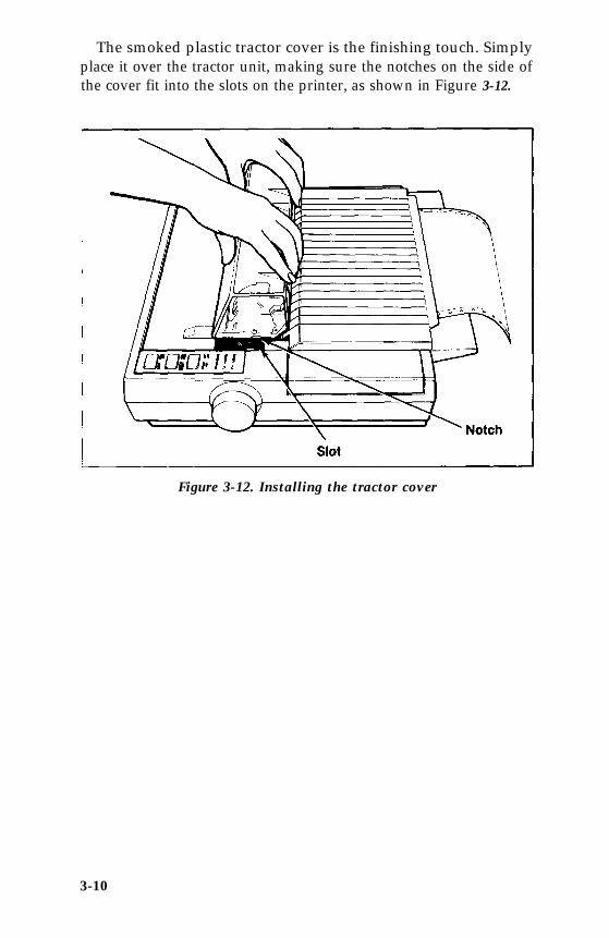
The smoked plastic tractor cover is the finishing touch. Simplyplace it over the tractor unit, making sure the notches on the side ofthe cover fit into the slots on the printer, as shown in Figure 3-12.
Figure 3-12. Installing the tractor cover
3-10
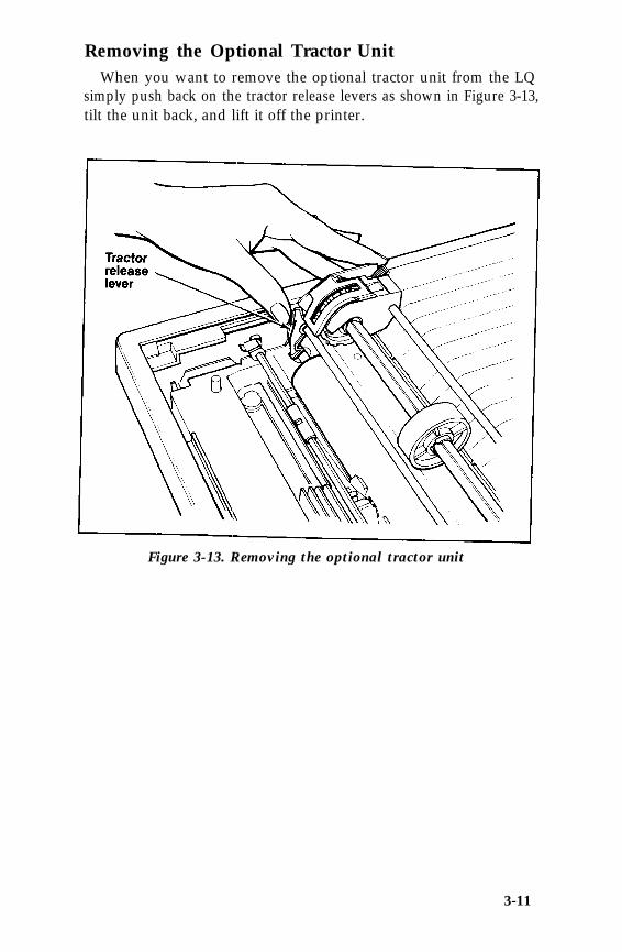
Removing the Optional Tractor UnitWhen you want to remove the optional tractor unit from the LQ
simply push back on the tractor release levers as shown in Figure 3-13,tilt the unit back, and lift it off the printer.
Figure 3-13. Removing the optional tractor unit
3-11
Chapter 4Using the LQ with Commercial Software
Now that you have set up and tested your printer, you can do anyof these things:
l Use the printer with commercial software (such as a word proces-sor, spreadsheet, or database).
l Learn about the features of the printer.
l Write programs to use the features of the printer.
Most of you probably want to begin using your LQ with commer-cial software to print such items as documents, reports, letters,spreadsheets, and graphics. This chapter tells you what you need toknow.
If you want to learn more about the features of the LQ, also readChapters 5 and 6. For programmers the important parts of the manualare the command summary and the other appendixes.
Using Commercial SoftwareCommercial software programs usually need to know what type of
printer you are using. You normally supply this information as part ofa setup or installation process. Either the manual for your program oran on-screen menu should explain this process for you.
The program may list a number of printers from which you canchoose. Pick LQ-800 or LQ-1000, depending on which printer youhave.
4-1
If neither one of these printers is listed, choose LQ-1500 becausethat printer recognizes virtually the same codes that the LQ-800 andLQ-1000 use. (If you have a program that does not list the LQ-1500 asan option, you may be able to obtain an update from the manufac-turer. Contact your software dealer or the manufacturer to see if anupdate that includes the LQ-1500, LQ-1000, or LQ-800 is available.)
If your program does not list any LQ printers, choose a printer fromthe list below. They are listed in order of preference.
FXLXRxMXEpson printerDraft printer
Once you have set up or installed your commercial software pro-gram for your printer, simply follow the program’s printing instruc-tions. If you have any trouble when you print, turn to the first sectionin Appendix D for help.
4-2
Chapter 5LQ Features
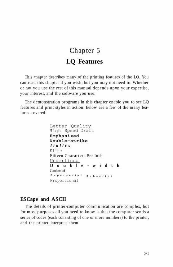
This chapter describes many of the printing features of the LQ. Youcan read this chapter if you wish, but you may not need to. Whetheror not you use the rest of this manual depends upon your expertise,your interest, and the software you use.
The demonstration programs in this chapter enable you to see LQfeatures and print styles in action. Below are a few of the many fea-tures covered:
Letter QualityHigh Speed Draft EmphasizedDouble-strikeI t a l i c sEliteFifteen Characters Per InchUnderlinedD o u b l e - w i d t hC o n d e n s e dS u p e r s c r i p t S u b s c r i p t
Proportional
ESCape and ASCIIThe details of printer-computer communication are complex, but
for most purposes all you need to know is that the computer sends aseries of codes (each consisting of one or more numbers) to the printer,and the printer interprets them.
5-1
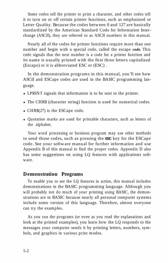
Some codes tell the printer to print a character, and other codes tellit to turn on or off certain printer functions, such as emphasized orLetter Quality. Because the codes between 0 and 127 are basicallystandardized by the American Standard Code for Information Inter-change (ASCII), they are referred to as ASCII numbers in this manual.
Nearly all of the codes for printer functions require more than onenumber and begin with a special code, called the escape code. Thiscode signals that the next number is a code for a printer function andits name is usually printed with the first three letters capitalized(Escape) or it is abbreviated ESC or (ESC) .
In the demonstration programs in this manual, you’ll see howASCII and ESCape codes are used in the BASIC programming lan-guage.
l LPRINT signals that information is to be sent to the printer.
l The CHR$ (character string) function is used for numerical codes.
l CHR$(27) is the ESCape code.
l Quotation marks are used for printable characters, such as letters ofthe alphabet.
Your word processing or business program may use other methodsto send those codes, such as pressing the ESC key for the ESCapecode. See your software manual for further information and useAppendix B of this manual to find the proper codes. Appendix D alsohas some suggestions on using LQ features with applications soft-ware.
Demonstration ProgramsTo enable you to see the LQ features in action, this manual includes
demonstrations in the BASIC programming language. Although youwill probably not do much of your printing using BASIC, the demon-strations are in BASIC because nearly all personal computer systemsinclude some version of this language. Therefore, almost everyonecan try the examples.
As you run the programs (or even as you read the explanations andlook at the printed examples), you learn how the LQ responds to themessages your computer sends it by printing letters, numbers, sym-bols, and graphics in various print modes.
5-2
Even if you never use BASIC again, you will know the capabilitiesof your printer, capabilities that can often solve your printing prob-lems. For example, if you need a special symbol, such as a Greek let-ter, you will know that you can turn to the chapter on user-definedcharacters and create such a character.
If you don’t want to do the exercises in BASIC, you don’t have to.In most cases the software that you use for word processing, business,or graphics does the calculating and communicating with the printerfor you. All you need to do is install your software as explained inChapter 4.
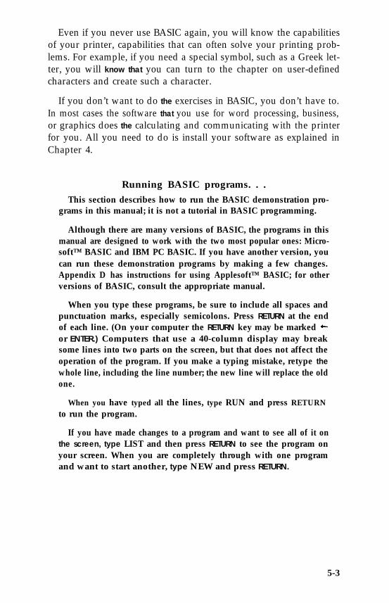
Running BASIC programs. . .This section describes how to run the BASIC demonstration pro-
grams in this manual; it is not a tutorial in BASIC programming.
Although there are many versions of BASIC, the programs in thismanual are designed to work with the two most popular ones: Micro-soft™ BASIC and IBM PC BASIC. If you have another version, youcan run these demonstration programs by making a few changes.Appendix D has instructions for using Applesoft™ BASIC; for otherversions of BASIC, consult the appropriate manual.
When you type these programs, be sure to include all spaces andpunctuation marks, especially semicolons. Press RETURN at the endof each line. (On your computer the RETURN key may be marked or ENTER.) Computers that use a 40-column display may breaksome lines into two parts on the screen, but that does not affect theoperation of the program. If you make a typing mistake, retype thewhole line, including the line number; the new line will replace the oldone.
When you have typed all the lines, type RUN and press RETURNto run the program.
If you have made changes to a program and want to see all of it onthe screen, type LIST and then press RETURN to see the program onyour screen. When you are completely through with one programand want to start another, type NEW and press RETURN.
5-3
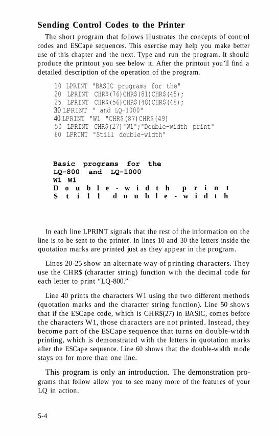
Sending Control Codes to the PrinterThe short program that follows illustrates the concepts of control
codes and ESCape sequences. This exercise may help you make betteruse of this chapter and the next. Type and run the program. It shouldproduce the printout you see below it. After the printout you’ll find adetailed description of the operation of the program.
10 LPRINT "BASIC programs for the"20 LPRINT CHR$(76)CHR$(81)CHR$(45);25 LPRINT CHR$(56)CHR$(48)CHR$(48);30 LPRINT " and LQ-1000"40 LPRINT "W1 "CHR$(87)CHR$(49)50 LPRINT CHR$(27)"W1";"Double-width print"60 LPRINT "Still double-width"
Basic programs for theLQ-800 and LQ-1000W1 W1D o u b l e - w i d t h p r i n tS t i l l d o u b l e - w i d t h
In each line LPRINT signals that the rest of the information on theline is to be sent to the printer. In lines 10 and 30 the letters inside thequotation marks are printed just as they appear in the program.
Lines 20-25 show an alternate way of printing characters. Theyuse the CHR$ (character string) function with the decimal code foreach letter to print “LQ-800.”
Line 40 prints the characters W1 using the two different methods(quotation marks and the character string function). Line 50 showsthat if the ESCape code, which is CHR$(27) in BASIC, comes beforethe characters W1, those characters are not printed. Instead, theybecome part of the ESCape sequence that turns on double-widthprinting, which is demonstrated with the letters in quotation marksafter the ESCape sequence. Line 60 shows that the double-width modestays on for more than one line.
This program is only an introduction. The demonstration pro-grams that follow allow you to see many more of the features of yourLQ in action.
5-4
Basic WidthsThe first programs print characters in the LQ’s three basic widths.
Further programs show you how to produce other character widthsby condensing and widening the basic ones.
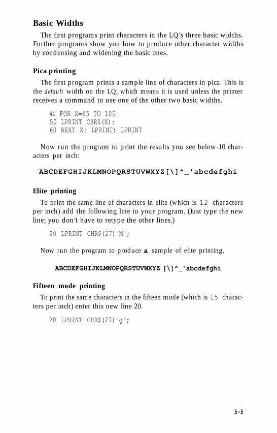
Pica printing
The first program prints a sample line of characters in pica. This isthe default width on the LQ, which means it is used unless the printerreceives a command to use one of the other two basic widths.
40 FOR X=65 TO 10550 LPRINT CHR$(X);60 NEXT X: LPRINT: LPRINT
Now run the program to print the results you see below-10 char-acters per inch:
ABCDEFGHIJKLMNOPQRSTUVWXYZ[\]^_'abcdefghi
Elite printing
To print the same line of characters in elite (which is 12 charactersper inch) add the following line to your program. (Just type the newline; you don’t have to retype the other lines.)
20 LPRINT CHR$(27)"M";
Now run the program to produce a sample of elite printing.
ABCDEFGHIJKLMNOPQRSTUVWXYZ [\]^_'abcdefghi
Fifteen mode printing
To print the same characters in the fifteen mode (which is 15 charac-ters per inch) enter this new line 20.
20 LPRINT CHR$(27)"g";
5-5
Now run the program to produce a sample of printing in the fifteenmode.
ABCDEFGHIJKLMNOPQRSTUVWXYZ[\]ˆ_'abcdefghi
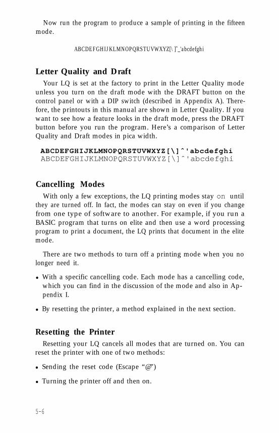
Letter Quality and DraftYour LQ is set at the factory to print in the Letter Quality mode
unless you turn on the draft mode with the DRAFT button on thecontrol panel or with a DIP switch (described in Appendix A). There-fore, the printouts in this manual are shown in Letter Quality. If youwant to see how a feature looks in the draft mode, press the DRAFTbutton before you run the program. Here’s a comparison of LetterQuality and Draft modes in pica width.
ABCDEFGHIJKLMNOPQRSTUVWXYZ[\]ˆ'abcdefghiABCDEFGHIJKLMNOPQRSTUVWXYZ[\]ˆ'abcdefghi
Cancelling ModesWith only a few exceptions, the LQ printing modes stay on until
they are turned off. In fact, the modes can stay on even if you changefrom one type of software to another. For example, if you run aBASIC program that turns on elite and then use a word processingprogram to print a document, the LQ prints that document in the elitemode.
There are two methods to turn off a printing mode when you nolonger need it.
l With a specific cancelling code. Each mode has a cancelling code,which you can find in the discussion of the mode and also in Ap-pendix I.
l By resetting the printer, a method explained in the next section.
Resetting the PrinterResetting your LQ cancels all modes that are turned on. You can
reset the printer with one of two methods:
l Sending the reset code (Escape “@”)
l Turning the printer off and then on.
5-6
Either one of these methods returns the printer to what are called itsdefaults, which are the standard settings in effect every time you turnthe printer on. Resetting the printer has two main effects. It returns theprinting to single-strike pica, thus cancelling any other pitches orenhancements you may have turned on, and the current position ofthe print head becomes the top-of-page setting. The reset code doesnot cancel the draft mode if it has been selected with the panel button,but turning off the printer does cancel the draft setting.
Some of the demonstration programs end with a reset code(Escape “@”) so that the commands from one program will not inter-fere with the commands in the next one. After you run a program witha reset code in it, remember to change the top-of-page setting beforeyou begin printing full pages.
Disabling a program’s reset code
Some word processors and other applications programs send a resetcode or initialization signal to the printer before sending data to beprinted. Basically, the purpose of this code or signal is to cancel anysettings that might interfere with the program’s print control options.
In most instances, this is fine. However, if you decide you want toset up the LQ to do something your applications program won’t do,you have to make sure a reset code doesn’t wipe out your new set-tings.
Some initialization codes can be removed by using the setup orinstallation procedures that are part of many applications programs.Once you’re into the setup procedure, find the section that deals withinitialization, and see if the program has a list of codes it sends to theprinter. If it does, the setup procedure usually allows you to cancel orremove the initialization settings.
If the initialization code cannot be disabled or removed from yourapplications program,. you can usually use the program’s print optionsfunction to control formatting and typestyles. Look in the manual forthe program to find out how to select print options.
5-7
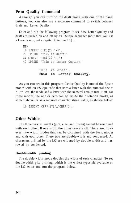
Print Quality CommandAlthough you can turn on the draft mode with one of the panel
buttons, you can also use a software command to switch betweendraft and Letter Quality.
Enter and run the following program to see how Letter Quality anddraft are turned on and off by an ESCape sequence (note that you usea lowercase x, not a capital X, in line 10).
NEW10 LPRINT CHR$(27)"x0";20 LPRINT "This is draft."30 LPRINT CHR$(27)"x1";40 LPRINT "This is Letter Quality."
This is draft.This is Letter Quality.
As you can see in this program, Letter Quality is one of the Epsonmodes with an ESCape code that uses a letter with the numeral one toturn on the mode and a letter with the numeral zero to turn it off. Forthese modes, the one or zero can be inside the quotation marks, asshown above, or as a separate character string value, as shown below:
10 LPRINT CHR$(27)"x"CHR$(0);
Other WidthsThe three basic widths (pica, elite, and fifteen) cannot be combined
with each other. If one is on, the other two are off. There are, how-ever, two width modes that can be combined with the basic modesand with each other. These two are double-width and condensed. Allcharacters printed by the LQ are widened by double-width and nar-rowed by condensed.
Double-width printing
The double-width mode doubles the width of each character. To seedouble-width pica printing, which is the widest typestyle available onthe LQ, enter and run the program below.
5-8
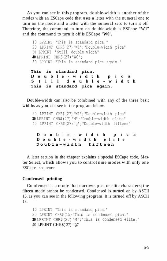
As you can see in this program, double-width is another of themodes with an ESCape code that uses a letter with the numeral one toturn on the mode and a letter with the numeral zero to turn it off.Therefore, the command to turn on double-width is ESCape “W1”and the command to turn it off is ESCape "W0".
10 LPRINT "This is standard pica."20 LPRINT CHR$(27)"W1";"Double-width pica"30 LPRINT "Still double-width"40 LPRINT CHR$(27)"W0";50 LPRINT "This is standard pica again."
This is standard pica.D o u b l e - w i d t h p i c aS t i l l d o u b l e - w i d t hThis is standard pica again.
Double-width can also be combined with any of the three basicwidths as you can see in the program below.
20 LPRINT CHR$(27)"W1";"Double-width pica"30 LPRINT CHR$(27)"M";"Double-width elite"40 LPRINT CHR$(27)"g";"Double-width fifteen"
D o u b l e - w i d t h p i c aD o u b l e - w i d t h e l i t eD o u b l e - w i d t h f i f t e e n
A later section in the chapter explains a special ESCape code, Mas-ter Select, which allows you to control nine modes with only oneESCape sequence.
Condensed printing
Condensed is a mode that narrows pica or elite characters; thefifteen mode cannot be condensed. Condensed is turned on by ASCII15, as you can see in the following program. It is turned off by ASCII18.
10 LPRINT "This is standard pica."20 LPRINT CHR$(15)"This is condensed pica."30 LPRINT CHR$(27) M" ";"This is condensed elite."40 LPRINT CHR$( 27) “@"
5-9
This is standard pica.This is condensed pica,This is condensed elite,
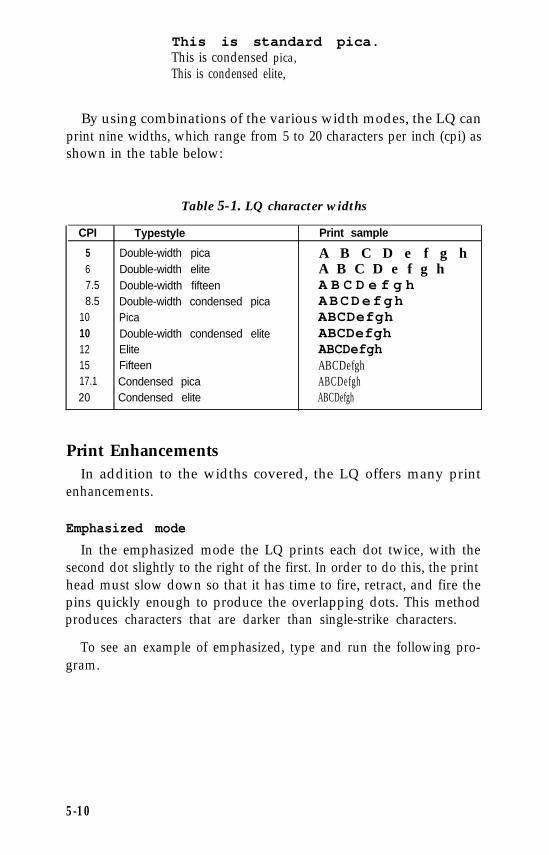
By using combinations of the various width modes, the LQ canprint nine widths, which range from 5 to 20 characters per inch (cpi) asshown in the table below:
Table 5-1. LQ character widths
CPI Typestyle Print sample
5 Double-width pica A B C D e f g h6 Double-width elite A B C D e f g h7.5 Double-width fifteen A B C D e f g h8.5 Double-width condensed pica ABCDefgh
10 Pica ABCDefgh10 Double-width condensed elite ABCDefgh12 Elite ABCDefgh15 Fifteen ABCDefgh17.1 Condensed pica ABCDefgh20 Condensed elite ABCDefgh
Print EnhancementsIn addition to the widths covered, the LQ offers many print
enhancements.
Emphasized mode
In the emphasized mode the LQ prints each dot twice, with thesecond dot slightly to the right of the first. In order to do this, the printhead must slow down so that it has time to fire, retract, and fire thepins quickly enough to produce the overlapping dots. This methodproduces characters that are darker than single-strike characters.
To see an example of emphasized, type and run the following pro-gram.
5-10
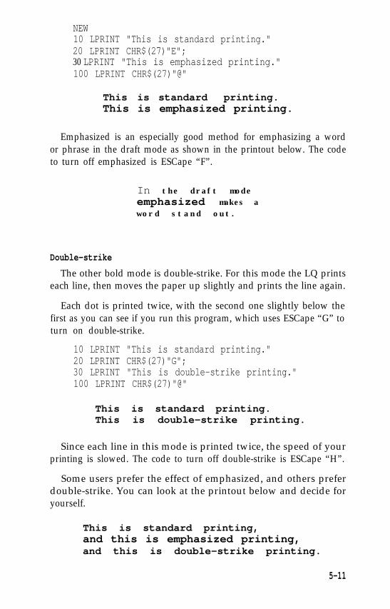
NEW10 LPRINT "This is standard printing."20 LPRINT CHR$(27)"E";30 LPRINT "This is emphasized printing."100 LPRINT CHR$(27)"@"
This is standard printing.This is emphasized printing.
Emphasized is an especially good method for emphasizing a wordor phrase in the draft mode as shown in the printout below. The codeto turn off emphasized is ESCape “F”.
In the draft modeemphasized makes aword stand out.
Double-strike
The other bold mode is double-strike. For this mode the LQ printseach line, then moves the paper up slightly and prints the line again.
Each dot is printed twice, with the second one slightly below thefirst as you can see if you run this program, which uses ESCape “G” toturn on double-strike.
10 LPRINT "This is standard printing."20 LPRINT CHR$(27)"G";30 LPRINT "This is double-strike printing."100 LPRINT CHR$(27)"@"
This is standard printing.This is double-strike printing.
Since each line in this mode is printed twice, the speed of yourprinting is slowed. The code to turn off double-strike is ESCape “H”.
Some users prefer the effect of emphasized, and others preferdouble-strike. You can look at the printout below and decide foryourself.
This is standard printing,and this is emphasized printing,and this is double-strike printing.
5-11
Underline mode
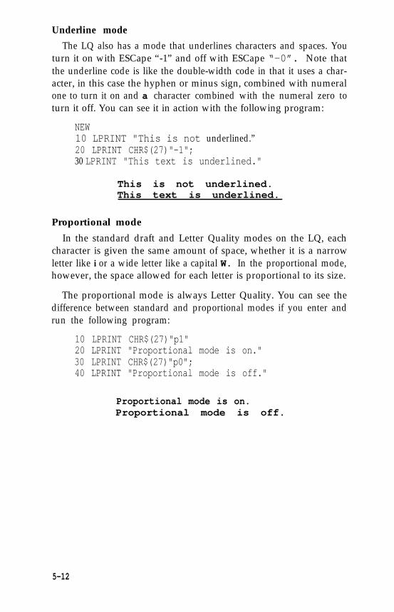
The LQ also has a mode that underlines characters and spaces. Youturn it on with ESCape “-1” and off with ESCape “-0”. Note thatthe underline code is like the double-width code in that it uses a char-acter, in this case the hyphen or minus sign, combined with numeralone to turn it on and a character combined with the numeral zero toturn it off. You can see it in action with the following program:
NEW10 LPRINT "This is not underlined.”20 LPRINT CHR$(27)"-1";30 LPRINT "This text is underlined."
This is not underlined.This text is underlined.
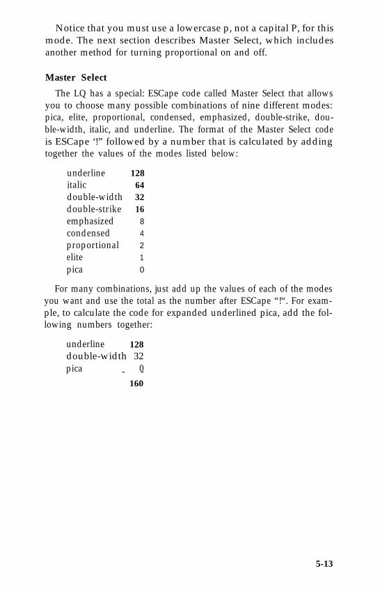
Proportional mode
In the standard draft and Letter Quality modes on the LQ, eachcharacter is given the same amount of space, whether it is a narrowletter like i or a wide letter like a capital W. In the proportional mode,however, the space allowed for each letter is proportional to its size.
The proportional mode is always Letter Quality. You can see thedifference between standard and proportional modes if you enter andrun the following program:
10 LPRINT CHR$(27)"p1"20 LPRINT "Proportional mode is on."30 LPRINT CHR$(27)"p0";40 LPRINT "Proportional mode is off."
Proportional mode is on.Proportional mode is off.
5-12
Notice that you must use a lowercase p, not a capital P, for thismode. The next section describes Master Select, which includesanother method for turning proportional on and off.
Master Select
The LQ has a special: ESCape code called Master Select that allowsyou to choose many possible combinations of nine different modes:pica, elite, proportional, condensed, emphasized, double-strike, dou-ble-width, italic, and underline. The format of the Master Select codeis ESCape ‘!” followed by a number that is calculated by addingtogether the values of the modes listed below:
underlineitalicdouble-widthdouble-strikeemphasizedcondensedproportionalelitepica
128643216
8
4
2
1
0
For many combinations, just add up the values of each of the modesyou want and use the total as the number after ESCape “!“. For exam-ple, to calculate the code for expanded underlined pica, add the fol-lowing numbers together:
underline 128double-width 32pica 0- -
160
5-13
To print this combination, therefore, you use ESCape “!” followedby the number 160. In the BASIC programming language the com-mand is CHR$(27)“!“CHR$(l60).
To try this number or any other, enter and run this short program,which will ask you for a Master Select number and then give you asample of printing using that code.
10 INPUT "Master Select number";M20 LPRINT CHR$(27)"!"CHR$(M)30 LPRINT "This sample uses"40 LPRINT "Master Select number";M50 LPRINT CHR$(27)"@"
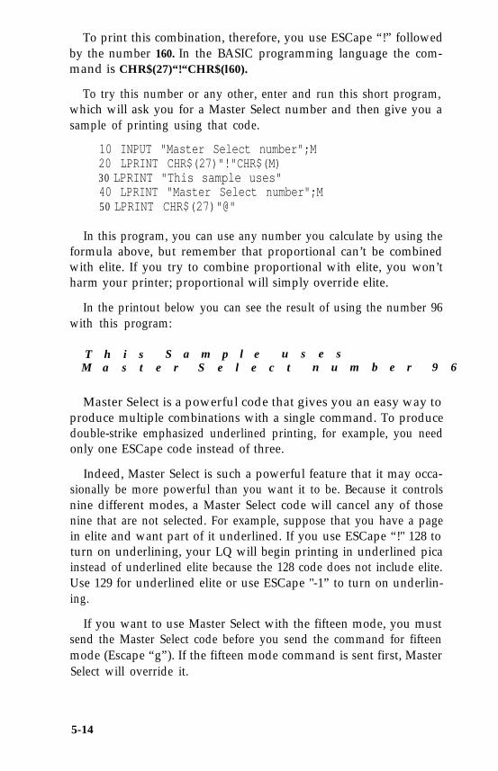
In this program, you can use any number you calculate by using theformula above, but remember that proportional can’t be combinedwith elite. If you try to combine proportional with elite, you won’tharm your printer; proportional will simply override elite.
In the printout below you can see the result of using the number 96with this program:
T h i s S a m p l e u s e sM a s t e r S e l e c t n u m b e r 9 6
Master Select is a powerful code that gives you an easy way toproduce multiple combinations with a single command. To producedouble-strike emphasized underlined printing, for example, you needonly one ESCape code instead of three.
Indeed, Master Select is such a powerful feature that it may occa-sionally be more powerful than you want it to be. Because it controlsnine different modes, a Master Select code will cancel any of thosenine that are not selected. For example, suppose that you have a pagein elite and want part of it underlined. If you use ESCape “!" 128 toturn on underlining, your LQ will begin printing in underlined picainstead of underlined elite because the 128 code does not include elite.Use 129 for underlined elite or use ESCape "-1” to turn on underlin-ing.
If you want to use Master Select with the fifteen mode, you mustsend the Master Select code before you send the command for fifteenmode (Escape “g”). If the fifteen mode command is sent first, MasterSelect will override it.
5-14
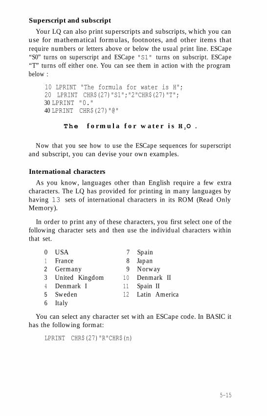
Superscript and subscript
Your LQ can also print superscripts and subscripts, which you canuse for mathematical formulas, footnotes, and other items thatrequire numbers or letters above or below the usual print line. ESCape“S0” turns on superscript and ESCape "S1" turns on subscript. ESCape“T” turns off either one. You can see them in action with the programbelow :
10 LPRINT "The formula for water is H";20 LPRINT CHR$(27)"S1";"2"CHR$(27)"T";30 LPRINT "0."40 LPRINT CHR$(27)"@"
The f o r m u l a f o r w a t e r i s H 2O .
Now that you see how to use the ESCape sequences for superscriptand subscript, you can devise your own examples.
International characters
As you know, languages other than English require a few extracharacters. The LQ has provided for printing in many languages byhaving 13 sets of international characters in its ROM (Read OnlyMemory).
In order to print any of these characters, you first select one of thefollowing character sets and then use the individual characters withinthat set.
0 USA 7 Spain1 France 8 Japan2 Germany 9 Norway3 United Kingdom 10 Denmark II4 Denmark I 11 Spain II5 Sweden 12 Latin America6 Italy
You can select any character set with an ESCape code. In BASIC ithas the following format:
LPRINT CHR$(27)"R"CHR$(n)
5-15
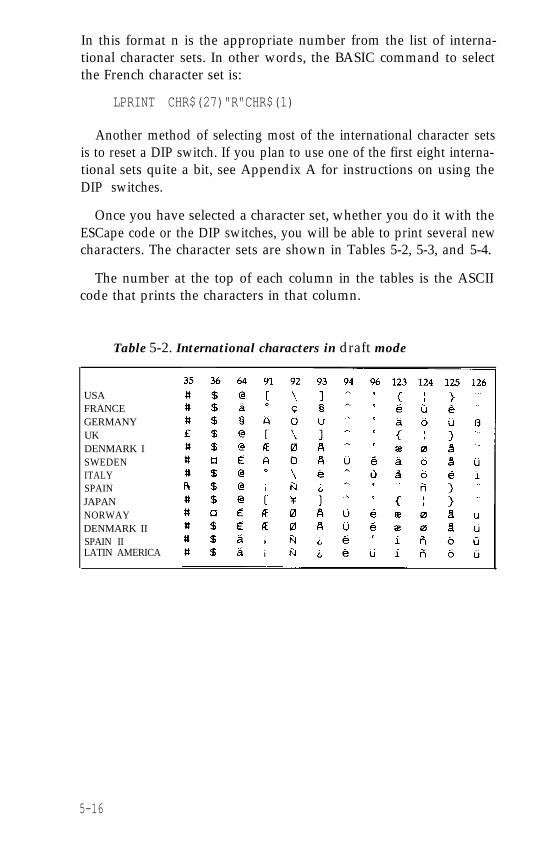
In this format n is the appropriate number from the list of interna-tional character sets. In other words, the BASIC command to selectthe French character set is:
LPRINT CHR$(27)"R"CHR$(1)
Another method of selecting most of the international character setsis to reset a DIP switch. If you plan to use one of the first eight interna-tional sets quite a bit, see Appendix A for instructions on using theDIP switches.
Once you have selected a character set, whether you do it with theESCape code or the DIP switches, you will be able to print several newcharacters. The character sets are shown in Tables 5-2, 5-3, and 5-4.
The number at the top of each column in the tables is the ASCIIcode that prints the characters in that column.
Table 5-2. International characters in draft mode
USAFRANCEGERMANYUKDENMARK ISWEDENITALYSPAINJAPANNORWAYDENMARK IISPAIN IILATIN AMERICA
5-16
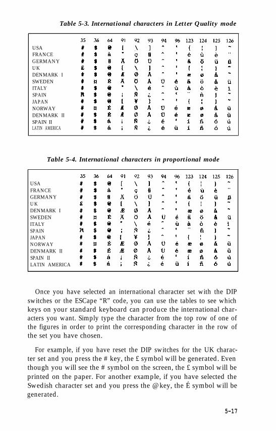
Table 5-3. International characters in Letter Quality mode
USAFRANCEGERMANYU KDENMARK ISWEDENITALYSPAINJAPANNORWAYDENMARK IISPAIN IILATIN AMERICA
Table 5-4. International characters in proportional mode
USAFRANCEGERMANYU KDENMARK ISWEDENITALYSPAINJAPANNORWAYDENMARK IISPAIN IILATIN AMERICA
Once you have selected an international character set with the DIPswitches or the ESCape “R” code, you can use the tables to see whichkeys on your standard keyboard can produce the international char-acters you want. Simply type the character from the top row of one ofthe figures in order to print the corresponding character in the row ofthe set you have chosen.
For example, if you have reset the DIP switches for the UK charac-ter set and you press the # key, the £ symbol will be generated. Eventhough you will see the # symbol on the screen, the £ symbol will beprinted on the paper. For another example, if you have selected theSwedish character set and you press the @ key, the É symbol will begenerated.
5-17
If your keyboard does not have one of the keys that you need, youwill have to send the proper ASCII number to the printer in anotherway, such as a programming language like BASIC.
Page FormattingAlthough the LQ printer has many sophisticated commands to set
margins, line spacing, horizontal and vertical tabs and character spac-ing, this section won’t take up your time with extensive discussions ofthese because most are taken care of by applications programs.Instead, this section describes a few commands that the average usermight need. For more information, see Appendix I, where all the com-mands are listed and described.
Margins
The LQ allows you to set the left and right margins with simpleESCape sequences. The left margin command is ESCape “1” followedby the number of the column you choose for the left margin. The rightmargin command is ESCape “Q” followed by the column number ofthe right margin you want. (For the left margin command, be sure touse a lowercase letter 1, not the numeral one.)
If your word processing program does not allow you to change themargins, you can send margin commands to your LQ with BASIC oranother programming language before you print your documents.For example, if you prefer wider margins than your word processingprogram gives you, run the following BASIC program before print-ing. This program gives you a left margin of 10 and a right margin of70, but you can use any numbers you prefer for the margin com-mands.
NEW10 LPRINT CHR$(27)"1"CHR$(l0);20 LPRINT CHR$(27)"Q"CHR$(70);
A program like this also allows you to choose the margins youprefer for program listings. Just remember that once you run a pro-gram that sets margins, those margins are in effect until you changethem with new margin commands or turn off or reset the printer.
5-18
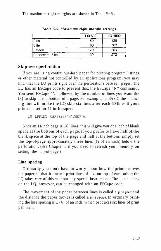
The maximum right margins are shown in Table 5-5.
Table 5-5. Maximum right margin settings
Skip-over-perforation
If you are using continuous-feed paper for printing program listingsor other material not controlled by an applications program, you mayfind that the LQ prints right over the perforations between pages. TheLQ has an ESCape code to prevent this: the ESCape “N” command.You send ESCape “N" followed by the number of lines you want theLQ to skip at the bottom of a page. For example, in BASIC the follow-ing line will make the LQ skip six lines after each 60 lines if yourprinter is set for 11-inch paper:
10 LPRINT CHR$(27)"N"CHR$(6);
Since an 11-inch page is 66 lines, this will give you one inch of blankspace at the bottom of each page. If you prefer to have half of theblank space at the top of the page and half at the bottom, simply setthe top-of-page approximately three lines (½ of an inch) below theperforation. (See Chapter 3 if you need to refresh your memory onsetting the top-of-page.)
Line spacing
Ordinarily you don’t have to worry about how the printer movesthe paper so that it doesn’t print lines of text on top of each other; theLQ takes care of this without any special instructions. The line spacingon the LQ, however, can be changed with an ESCape code.
The movement of the paper between lines is called a fine feed andthe distance the paper moves is called a line space. In ordinary print-ing the line spacing is 1/6 of an inch, which produces six lines of printper inch.
5-19
The standard line spacing is the only one you need for almost allprinting of text, but in some cases you may want to increase ordecrease the space between lines. The LQ has several commands to dothis, one of which specifies the line spacing in 180ths of an inch. If youneed to make such fine adjustments in the line spacing, see Appendix Ifor the proper commands. In Chapter 6 you’ll see how useful changesin line spacing can be for dot graphics.
Half-speed ModeWhen quiet is more important than speed, you can use ESCape “s”
to cut the printing speed in half. ESCape “s1” turns the half-speedmode on, and ESCape “s0” turns it off. Note that you use a lowercases, not a capital S for this code.
Printing to the End of the PageIn order to protect the print head and platen, the LQ stops printing
three lines from the end of the paper. This means that when you areprinting on single sheets, you cannot use the last three lines of thepage, but that is usually reserved for the bottom margin anyway.
5-20
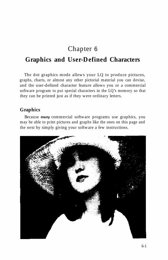
Chapter 6Graphics and User-Defined Characters
The dot graphics mode allows your LQ to produce pictures,graphs, charts, or almost any other pictorial material you can devise,and the user-defined character feature allows you or a commercialsoftware program to put special characters in the LQ’s memory so thatthey can be printed just as if they were ordinary letters.
GraphicsBecause many commercial software programs use graphics, you
may be able to print pictures and graphs like the ones on this page andthe next by simply giving your software a few instructions.
6-1
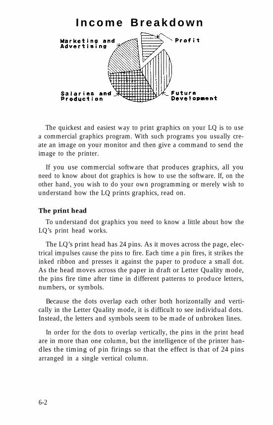
I n c o m e B r e a k d o w n
The quickest and easiest way to print graphics on your LQ is to usea commercial graphics program. With such programs you usually cre-ate an image on your monitor and then give a command to send theimage to the printer.
If you use commercial software that produces graphics, all youneed to know about dot graphics is how to use the software. If, on theother hand, you wish to do your own programming or merely wish tounderstand how the LQ prints graphics, read on.
The print head
To understand dot graphics you need to know a little about how theLQ’s print head works.
The LQ’s print head has 24 pins. As it moves across the page, elec-trical impulses cause the pins to fire. Each time a pin fires, it strikes theinked ribbon and presses it against the paper to produce a small dot.As the head moves across the paper in draft or Letter Quality mode,the pins fire time after time in different patterns to produce letters,numbers, or symbols.
Because the dots overlap each other both horizontally and verti-cally in the Letter Quality mode, it is difficult to see individual dots.Instead, the letters and symbols seem to be made of unbroken lines.
In order for the dots to overlap vertically, the pins in the print headare in more than one column, but the intelligence of the printer han-dles the timing of pin firings so that the effect is that of 24 pinsarranged in a single vertical column.
6-2
Dot patterns
The LQ’s print head is able to print graphics as well as text becausegraphic images are formed on the LQ about the same way that pic-tures in newspapers and magazines are printed. If you look closely at anewspaper photograph, you can see that it is made up of many smalldots. The LQ also forms its images with patterns of dots, as many as360 dot positions per inch horizontally and 180 dots vertically. Theimages printed by the LQ can, therefore, be as finely detailed as theone on the first page of this chapter.
Eight-pin graphics
So that it is compatible with the many programs written for suchprinters such as the Epson FX and RX series, the LQ has an 8-pingraphics mode with six densities. Although this mode uses only onethird of the LQ’s pins, it produces good quality graphics and allowsyou to use the many programs written for 8-pin graphics.
Twenty-four-pin graphics
The graphics mode that takes full advantage of the LQ’s print headis 24-pin graphics. It has five densities, but for simplicity this explana-tion will begin with only one of them, triple-density.
Triple-density prints up to 180 dots per inch horizontally. As theprint head moves across the paper, every 1/180th of an inch it mustreceive instructions about which of its 24 pins to fire. At each positionit can fire any number of pins from none to 24. This means that theprinter must receive 24 bits of information for each column it prints.Since the LQ uses 8-bit bytes of information in its communicationwith a computer, it needs three bytes of information for each position.
Pin labels
To tell the printer which pins to fire in each column, you first divideeach of the vertical columns into three sections of eight pins each andconsider each section separately. Since there are 256 possible combina-tions of the eight pins in each section, you need a numbering systemthat allows you to use a single number to specify which of the 256possible patterns you want. This numbering system is shown in Figure6-1.
6-3
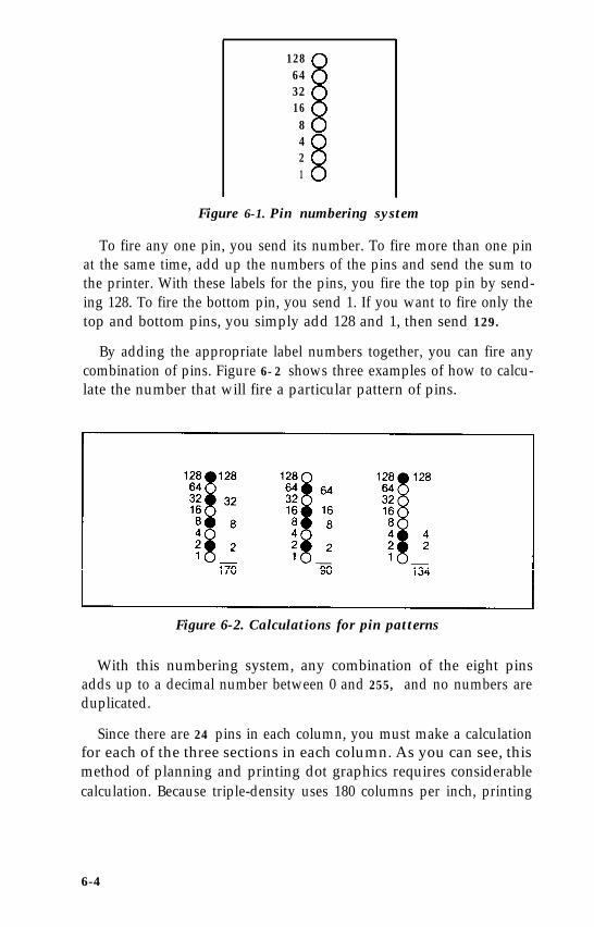
1286432168421
Figure 6-1. Pin numbering system
To fire any one pin, you send its number. To fire more than one pinat the same time, add up the numbers of the pins and send the sum tothe printer. With these labels for the pins, you fire the top pin by send-ing 128. To fire the bottom pin, you send 1. If you want to fire only thetop and bottom pins, you simply add 128 and 1, then send 129.
By adding the appropriate label numbers together, you can fire anycombination of pins. Figure 6-2 shows three examples of how to calcu-late the number that will fire a particular pattern of pins.
Figure 6-2. Calculations for pin patterns
With this numbering system, any combination of the eight pinsadds up to a decimal number between 0 and 255, and no numbers areduplicated.
Since there are 24 pins in each column, you must make a calculationfor each of the three sections in each column. As you can see, thismethod of planning and printing dot graphics requires considerablecalculation. Because triple-density uses 180 columns per inch, printing
6-4
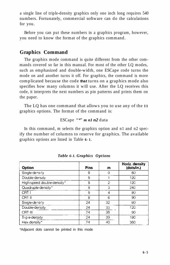
a single line of triple-density graphics only one inch long requires 540numbers. Fortunately, commercial software can do the calculationsfor you.
Before you can put these numbers in a graphics program, however,you need to know the format of the graphics command.
Graphics CommandThe graphics mode command is quite different from the other com-
mands covered so far in this manual. For most of the other LQ modes,such as emphasized and double-width, one ESCape code turns themode on and another turns it off. For graphics, the command is morecomplicated because the code that turns on a graphics mode alsospecifies how many columns it will use. After the LQ receives thiscode, it interprets the next numbers as pin patterns and prints them onthe paper.
The LQ has one command that allows you to use any of the 11graphics options. The format of the command is:
ESCape “*” m n1 n2 data
In this command, m selects the graphics option and n1 and n2 spec-ify the number of columns to reserve for graphics. The availablegraphics options are listed in Table 6-1.
Table 6-1. Graphics Options
*Adjacent dots cannot be printed in this mode
6-5
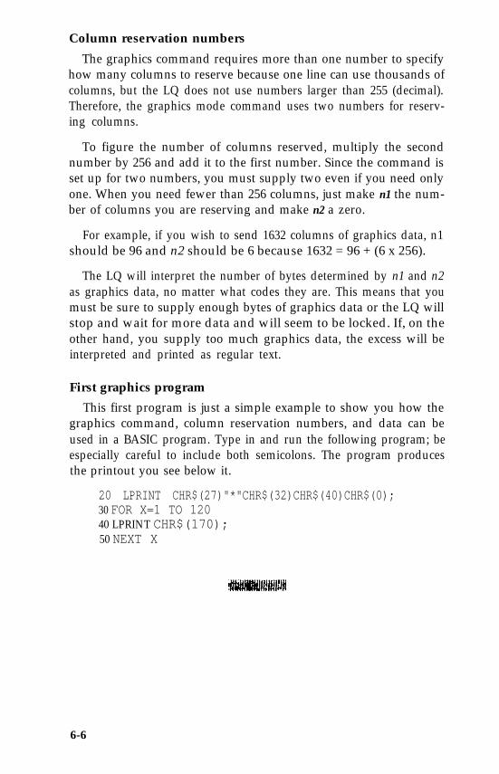
Column reservation numbers
The graphics command requires more than one number to specifyhow many columns to reserve because one line can use thousands ofcolumns, but the LQ does not use numbers larger than 255 (decimal).Therefore, the graphics mode command uses two numbers for reserv-ing columns.
To figure the number of columns reserved, multiply the secondnumber by 256 and add it to the first number. Since the command isset up for two numbers, you must supply two even if you need onlyone. When you need fewer than 256 columns, just make n1 the num-ber of columns you are reserving and make n2 a zero.
For example, if you wish to send 1632 columns of graphics data, n1should be 96 and n2 should be 6 because 1632 = 96 + (6 x 256).
The LQ will interpret the number of bytes determined by n1 and n2as graphics data, no matter what codes they are. This means that youmust be sure to supply enough bytes of graphics data or the LQ willstop and wait for more data and will seem to be locked. If, on theother hand, you supply too much graphics data, the excess will beinterpreted and printed as regular text.
First graphics program
This first program is just a simple example to show you how thegraphics command, column reservation numbers, and data can beused in a BASIC program. Type in and run the following program; beespecially careful to include both semicolons. The program producesthe printout you see below it.
20 LPRINT CHR$(27)"*"CHR$(32)CHR$(40)CHR$(0);30 FOR X=1 TO 12040 LPRINT CHR$(170);50 NEXT X
6-6
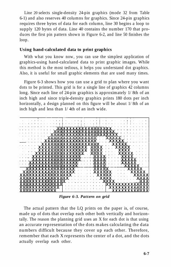
Line 20 selects single-density 24-pin graphics (mode 32 from Table6-1) and also reserves 40 columns for graphics. Since 24-pin graphicsrequires three bytes of data for each column, line 30 begins a loop tosupply 120 bytes of data. Line 40 contains the number 170 that pro-duces the first pin pattern shown in Figure 6-2, and line 50 finishes theloop.
Using hand-calculated data to print graphics
With what you know now, you can use the simplest application ofgraphics-using hand-calculated data to print graphic images. Whilethis method is the most tedious, it helps you understand dot graphics.Also, it is useful for small graphic elements that are used many times.
Figure 6-3 shows how you can use a grid to plan where you wantdots to be printed. This grid is for a single line of graphics 42 columnslong. Since each line of 24-pin graphics is approximately 1/8th of aninch high and since triple-density graphics prints 180 dots per inchhorizontally, a design planned on this figure will be about 1/8th of aninch high and less than 1/4th of an inch wide.
Figure 6-3. Pattern on grid
The actual pattern that the LQ prints on the paper is, of course,made up of dots that overlap each other both vertically and horizon-tally. The reason the planning grid uses an X for each dot is that usingan accurate representation of the dots makes calculating the datanumbers difficult because they cover up each other. Therefore,remember that each X represents the center of a dot, and the dotsactually overlap each other.
6-7
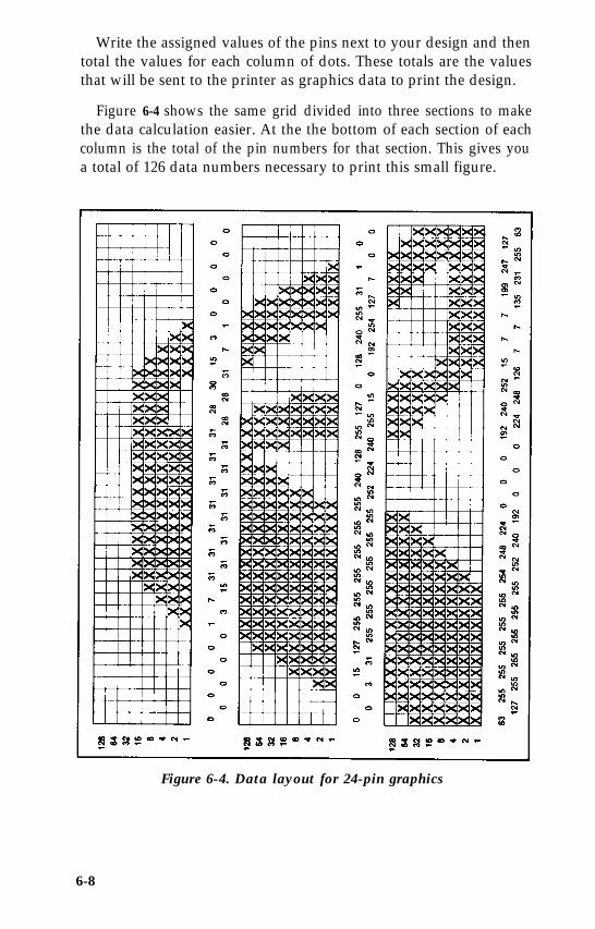
Write the assigned values of the pins next to your design and thentotal the values for each column of dots. These totals are the valuesthat will be sent to the printer as graphics data to print the design.
Figure 6-4 shows the same grid divided into three sections to makethe data calculation easier. At the the bottom of each section of eachcolumn is the total of the pin numbers for that section. This gives youa total of 126 data numbers necessary to print this small figure.
Figure 6-4. Data layout for 24-pin graphics
6-8
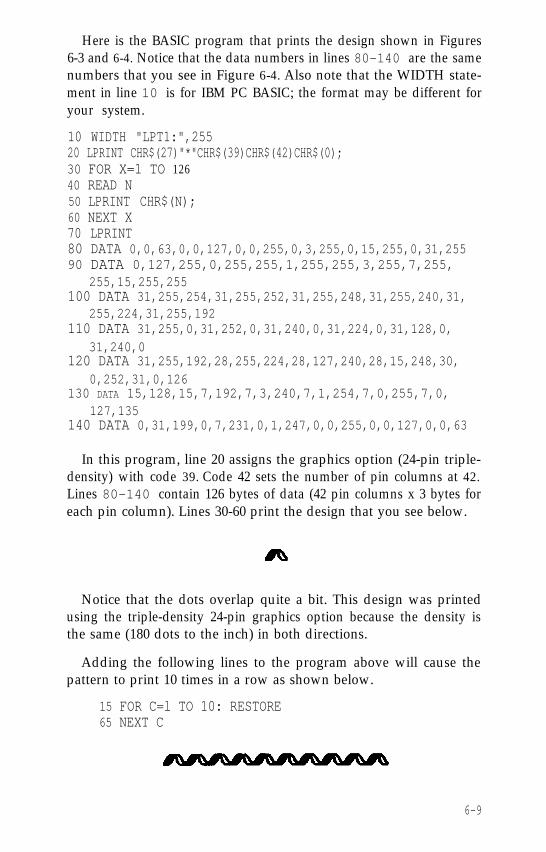
Here is the BASIC program that prints the design shown in Figures6-3 and 6-4. Notice that the data numbers in lines 80-140 are the samenumbers that you see in Figure 6-4. Also note that the WIDTH state-ment in line 10 is for IBM PC BASIC; the format may be different foryour system.
10 WIDTH "LPT1:",25520 LPRINT CHR$(27)"*"CHR$(39)CHR$(42)CHR$(0); 30 FOR X=1 TO 12640 READ N50 LPRINT CHR$(N);60 NEXT X70 LPRINT80 DATA 0,0,63,0,0,127,0,0,255,0,3,255,0,15,255,0,31,25590 DATA 0,127,255,0,255,255,1,255,255,3,255,7,255,
255,15,255,255100 DATA 31,255,254,31,255,252,31,255,248,31,255,240,31,
255,224,31,255,192110 DATA 31,255,0,31,252,0,31,240,0,31,224,0,31,128,0,
31,240,0120 DATA 31,255,192,28,255,224,28,127,240,28,15,248,30,
0,252,31,0,126130 DATA 15,128,15,7,192,7,3,240,7,1,254,7,0,255,7,0,
127,135140 DATA 0,31,199,0,7,231,0,1,247,0,0,255,0,0,127,0,0,63
In this program, line 20 assigns the graphics option (24-pin triple-density) with code 39. Code 42 sets the number of pin columns at 42.Lines 80-140 contain 126 bytes of data (42 pin columns x 3 bytes foreach pin column). Lines 30-60 print the design that you see below.
Notice that the dots overlap quite a bit. This design was printedusing the triple-density 24-pin graphics option because the density isthe same (180 dots to the inch) in both directions.
Adding the following lines to the program above will cause thepattern to print 10 times in a row as shown below.
15 FOR C=l TO 10: RESTORE65 NEXT C
6-9
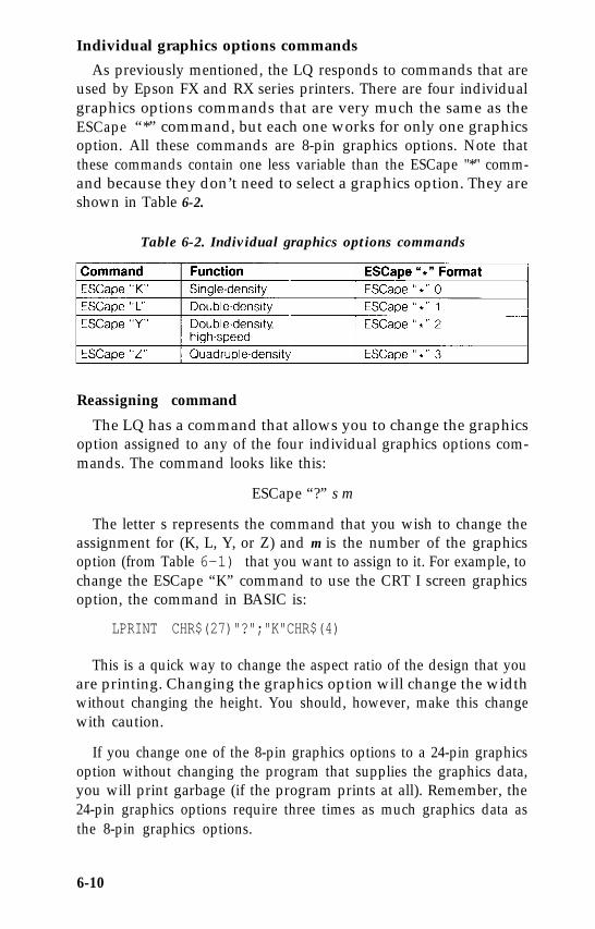
Individual graphics options commands
As previously mentioned, the LQ responds to commands that areused by Epson FX and RX series printers. There are four individualgraphics options commands that are very much the same as theESCape “*” command, but each one works for only one graphicsoption. All these commands are 8-pin graphics options. Note thatthese commands contain one less variable than the ESCape "*" comm-and because they don’t need to select a graphics option. They areshown in Table 6-2.
Table 6-2. Individual graphics options commands
Reassigning command
The LQ has a command that allows you to change the graphicsoption assigned to any of the four individual graphics options com-mands. The command looks like this:
ESCape “?” s m
The letter s represents the command that you wish to change theassignment for (K, L, Y, or Z) and m is the number of the graphicsoption (from Table 6-1) that you want to assign to it. For example, tochange the ESCape “K” command to use the CRT I screen graphicsoption, the command in BASIC is:
LPRINT CHR$(27)"?";"K"CHR$(4)
This is a quick way to change the aspect ratio of the design that youare printing. Changing the graphics option will change the widthwithout changing the height. You should, however, make this changewith caution.
If you change one of the 8-pin graphics options to a 24-pin graphicsoption without changing the program that supplies the graphics data,you will print garbage (if the program prints at all). Remember, the24-pin graphics options require three times as much graphics data asthe 8-pin graphics options.
6-10
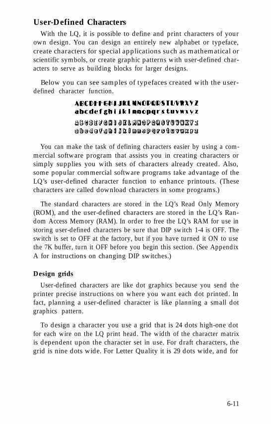
User-Defined CharactersWith the LQ, it is possible to define and print characters of your
own design. You can design an entirely new alphabet or typeface,create characters for special applications such as mathematical orscientific symbols, or create graphic patterns with user-defined char-acters to serve as building blocks for larger designs.
Below you can see samples of typefaces created with the user-defined character function.
You can make the task of defining characters easier by using a com-mercial software program that assists you in creating characters orsimply supplies you with sets of characters already created. Also,some popular commercial software programs take advantage of theLQ’s user-defined character function to enhance printouts. (Thesecharacters are called download characters in some programs.)
The standard characters are stored in the LQ’s Read Only Memory(ROM), and the user-defined characters are stored in the LQ’s Ran-dom Access Memory (RAM). In order to free the LQ’s RAM for use instoring user-defined characters be sure that DIP switch 1-4 is OFF. Theswitch is set to OFF at the factory, but if you have turned it ON to usethe 7K buffer, turn it OFF before you begin this section. (See AppendixA for instructions on changing DIP switches.)
Design grids
User-defined characters are like dot graphics because you send theprinter precise instructions on where you want each dot printed. Infact, planning a user-defined character is like planning a small dotgraphics pattern.
To design a character you use a grid that is 24 dots high-one dotfor each wire on the LQ print head. The width of the character matrixis dependent upon the character set in use. For draft characters, thegrid is nine dots wide. For Letter Quality it is 29 dots wide, and for
6-11
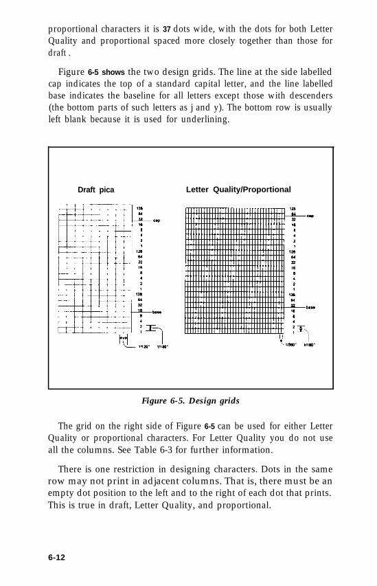
proportional characters it is 37 dots wide, with the dots for both LetterQuality and proportional spaced more closely together than those fordraft .
Figure 6-5 shows the two design grids. The line at the side labelledcap indicates the top of a standard capital letter, and the line labelledbase indicates the baseline for all letters except those with descenders(the bottom parts of such letters as j and y). The bottom row is usuallyleft blank because it is used for underlining.
Draft pica Letter Quality/Proportional
Figure 6-5. Design grids
The grid on the right side of Figure 6-5 can be used for either LetterQuality or proportional characters. For Letter Quality you do not useall the columns. See Table 6-3 for further information.
There is one restriction in designing characters. Dots in the samerow may not print in adjacent columns. That is, there must be anempty dot position to the left and to the right of each dot that prints.This is true in draft, Letter Quality, and proportional.
6-12
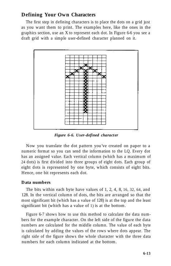
Defining Your Own CharactersThe first step in defining characters is to place the dots on a grid just
as you want them to print. The examples here, like the ones in thegraphics section, use an X to represent each dot. In Figure 6-6 you see adraft grid with a simple user-defined character planned on it.
Figure 6-6. User-defined character
Now you translate the dot pattern you’ve created on paper to anumeric format so you can send the information to the LQ. Every dothas an assigned value. Each vertical column (which has a maximum of24 dots) is first divided into three groups of eight dots. Each group ofeight dots is represented by one byte, which consists of eight bits.Hence, one bit represents each dot.
Data numbers
The bits within each byte have values of 1, 2, 4, 8, 16, 32, 64, and128. In the vertical column of dots, the bits are arranged so that themost significant bit (which has a value of 128) is at the top and the leastsignificant bit (which has a value of 1) is at the bottom.
Figure 6-7 shows how to use this method to calculate the data num-bers for the example character. On the left side of the figure the datanumbers are calculated for the middle column. The value of each byteis calculated by adding the values of the rows where dots appear. Theright side of the figure shows the whole character with the three datanumbers for each column indicated at the bottom.
6-13
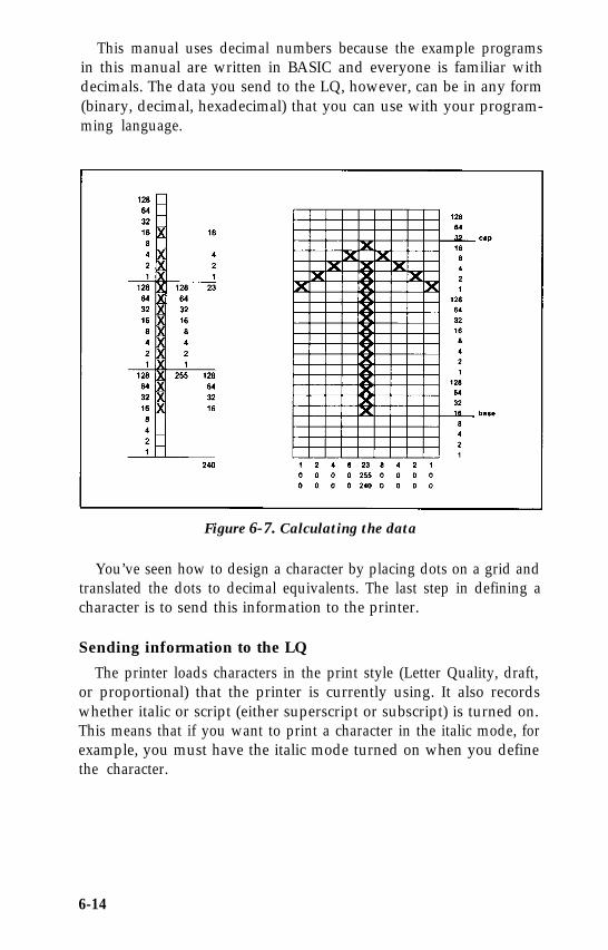
This manual uses decimal numbers because the example programsin this manual are written in BASIC and everyone is familiar withdecimals. The data you send to the LQ, however, can be in any form(binary, decimal, hexadecimal) that you can use with your program-ming language.
Figure 6-7. Calculating the data
You’ve seen how to design a character by placing dots on a grid andtranslated the dots to decimal equivalents. The last step in defining acharacter is to send this information to the printer.
Sending information to the LQ
The printer loads characters in the print style (Letter Quality, draft,or proportional) that the printer is currently using. It also recordswhether italic or script (either superscript or subscript) is turned on.This means that if you want to print a character in the italic mode, forexample, you must have the italic mode turned on when you definethe character.
6-14
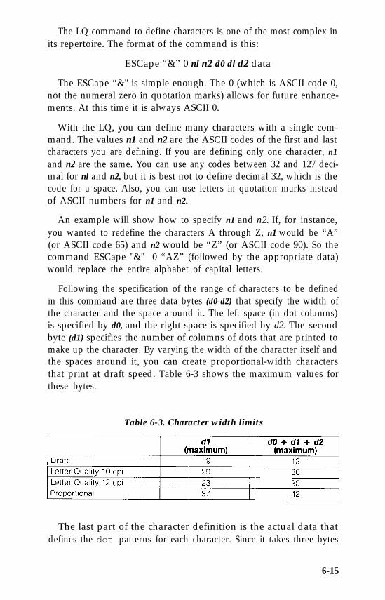
The LQ command to define characters is one of the most complex inits repertoire. The format of the command is this:
ESCape “&” 0 nl n2 d0 dl d2 data
The ESCape “&" is simple enough. The 0 (which is ASCII code 0,not the numeral zero in quotation marks) allows for future enhance-ments. At this time it is always ASCII 0.
With the LQ, you can define many characters with a single com-mand. The values n1 and n2 are the ASCII codes of the first and lastcharacters you are defining. If you are defining only one character, n1and n2 are the same. You can use any codes between 32 and 127 deci-mal for nl and n2, but it is best not to define decimal 32, which is thecode for a space. Also, you can use letters in quotation marks insteadof ASCII numbers for n1 and n2.
An example will show how to specify n1 and n2. If, for instance,you wanted to redefine the characters A through Z, n1 would be “A”(or ASCII code 65) and n2 would be “Z” (or ASCII code 90). So thecommand ESCape "&" 0 “AZ” (followed by the appropriate data)would replace the entire alphabet of capital letters.
Following the specification of the range of characters to be definedin this command are three data bytes (d0-d2) that specify the width ofthe character and the space around it. The left space (in dot columns)is specified by d0, and the right space is specified by d2. The secondbyte (d1) specifies the number of columns of dots that are printed tomake up the character. By varying the width of the character itself andthe spaces around it, you can create proportional-width charactersthat print at draft speed. Table 6-3 shows the maximum values forthese bytes.
Table 6-3. Character width limits
The last part of the character definition is the actual data thatdefines the dot patterns for each character. Since it takes three bytes
6-15
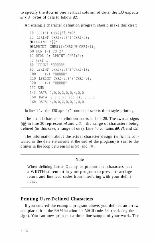
to specify the dots in one vertical column of dots, the LQ expectsdl x 3 bytes of data to follow d2.
An example character definition program should make this clear:
10 LPRINT CHR$(27)"x0"20 LPRINT CHR$(27)"&"CHR$(0);30 LPRINT "@@";40 LPRINT CHR$(1)CHR$(9)CHR$(l);50 FOR I=1 TO 2760 READ A: LPRINT CHR$(A);70 NEXT I80 LPRINT "@@@@@"90 LPRINT CHR$(27)"%"CHR$(l);100 LPRINT "@@@@@"110 LPRINT CHR$(27)"%"CHR$(0);120 LPRINT "@@@@@"130 END140 DATA 1,0,0,2,0,0,4,0,0150 DATA 8,0,0,23,255,240,8,0,0160 DATA 4,0,0,2,0,0,1,0,0
In line 10, the ESCape “x” command selects draft style printing.
The actual character definition starts in line 20. The two at signs(@) in line 30 represent nl and n2, the range of characters beingdefined (in this case, a range of one). Line 40 contains d0, dl, and d2.
The information about the actual character design (which is con-tained in the data statements at the end of the program) is sent to theprinter in the loop between lines 50 and 70.
Note
When defining Letter Quality or proportional characters, puta WIDTH statement in your program to prevent carriagereturn and line feed codes from interfering with your defini-tions .
Printing User-Defined CharactersIf you entered the example program above, you defined an arrow
and placed it in the RAM location for ASCII code 64 (replacing the atsign). You can now print out a three line sample of your work. The
6-16
first and third lines (printed by lines 80 and 120 of the program) printthe normal at sign; the second line (line 100) prints the arrow that youdefined. Run the program to see the printout below:
@@@@@
@@@@@
As you can see, both sets of characters (the original ROM charac-ters that the printer normally uses and the user-defined character set)remain in the printer available for your use. The command to switchbetween the two sets is used in lines 90 and 110. It is:
ESCape “%” n
If n is equal to 0, the normal ROM character set is selected (this isthe default). If n is equal to 1, the user-defined character set is selected.If you select the user-defined character set before you have definedany characters, the command is ignored; the ROM characters will stillbe in use.
You may switch between character sets at any time-even in themiddle of a line. To try it, place semicolons at the end of lines 80 and100 in the program above.
Copying ROM to RAM
After running the program above, if you select the user-definedcharacter set and try to print other characters, the only one that willprint is the arrow. Since no other characters are in the user-definedRAM area, nothing else prints. Other characters sent to the printerdon’t even print as spaces; it’s as if they were not sent at all.
In many cases, you will want to redefine only a few of the charac-ters to suit your needs; the rest of the alphabet will work fine as it is.As you have seen, it is possible to switch back and forth at willbetween the normal character set and the user-defined character set. Itis, however, rather inconvenient.
Therefore, the LQ has a command which allows you to copy all ofthe standard characters from ROM to the user-defined character set.The command format is:
ESCape “:“ 0 0 0
6-17
Note
This command will cancel any user-defined characters youhave created. You must send this command to the printerbefore you define characters.
If you use this command at the beginning of a program, then defineyour special characters and select the user-defined character set, youcan print with the user-defined set as your normal character set. You’llnever need to switch back and forth between sets.
Letter Quality characters
If you select Letter Quality printing with the ESCape “xl” com-mand, you can design user-defined characters using up to 29 columnsof the Letter Quality/Proportional grid. The dot columns are spacedcloser together horizontally than draft style dot columns (the horizon-tal dot spacing is 1/360th of an inch as opposed to 1/120th of an inchfor draft characters).
Proportional mode characters
Selecting the proportional character mode will yield user-definedcharacters of the highest resolution. Characters can be designed usingall 37 columns of the Letter Quality/Proportional grid.
Remember that in Letter Quality and proportional, as in draft, youcannot place dots in adjacent columns. There must be an empty dotposition to the left and right of each dot that prints.
Superscripts and subscripts
You can also create superscript and subscript user-defined charac-ters. Just as Letter Quality characters are defined when the LetterQuality mode is selected, super/subscript characters are created wheneither superscript or subscript is selected.
These super/subscript characters can be used either as superscriptsor as subscripts. The characters are exactly the same; it is only theirplacement that differs. The difference between super/subscript
6-18
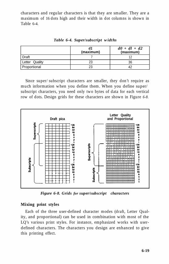
characters and regular characters is that they are smaller. They are amaximum of 16 dots high and their width in dot columns is shown inTable 6-4.
Table 6-4. Super/subscript widths
DraftLetter QualityProportional
d1 d0 + dl + d2(maximum) (maximum)
7 1223 3623 42
Since super/subscript characters are smaller, they don’t require asmuch information when you define them. When you define super/subscript characters, you need only two bytes of data for each verticalrow of dots. Design grids for these characters are shown in Figure 6-8.
Draft picaLetter Quality
and Proportional
Figure 6-8. Grids for super/subscript characters
Mixing print styles
Each of the three user-defined character modes (draft, Letter Qual-ity, and proportional) can be used in combination with most of theLQ’s various print styles. For instance, emphasized works with user-defined characters. The characters you design are enhanced to givethis printing effect.
6-19
Mixing the three types of user-defined characters is not permitted.If, for example, you select draft and define some characters, thenselect proportional and define some more, the first character defini-tions will be destroyed. Only one type of character definition may bestored in RAM at any time.
If you define characters in one mode, then switch to another modeand select the user-defined character set, the command will be ignoredand nothing will print. The user-defined character definitions, how-ever, remain unaffected. If you switch back to the mode in which theywere defined, you can then select and print them.
Keep in mind that user-defined characters are stored in RAM,which is not permanent. Whenever the printer power is turned off, orthe printer is initialized with the ESCape “@" command, all of theuser-defined characters are lost. Also, your computer sometimessends an initialization (INIT) signal, which wipes out all user-definedcharacters. (Some computers do this each time BASIC is loaded.)
6-20
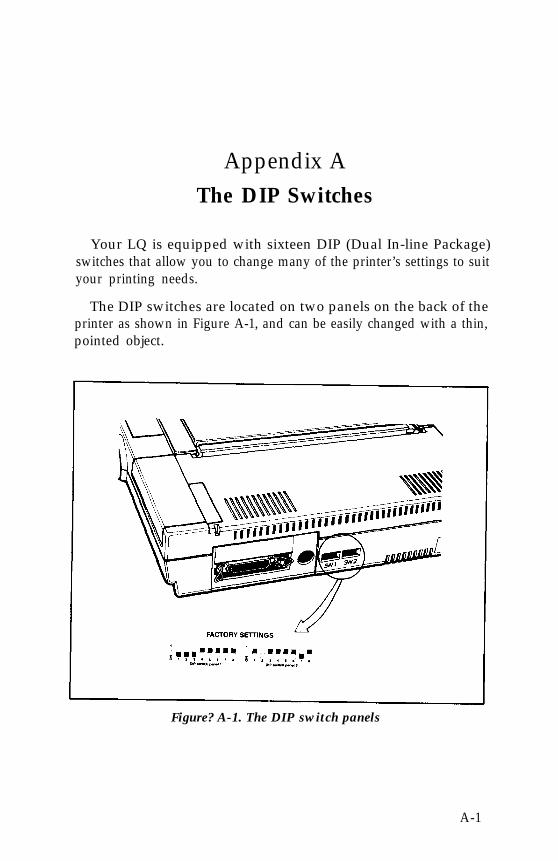
Appendix AThe DIP Switches
Your LQ is equipped with sixteen DIP (Dual In-line Package)switches that allow you to change many of the printer’s settings to suityour printing needs.
The DIP switches are located on two panels on the back of theprinter as shown in Figure A-1, and can be easily changed with a thin,pointed object.
Figure? A-1. The DIP switch panels
A-1
If you are using the serial interface on the LQ, then you need tocheck switches 2-3, 2-4, 2-5, and 2-6 to make sure the settings matchthose on your computer.
Remember
Each time you change a DIP switch setting, you should turnthe power OFF reset the switch or switches, then turn thepower ON again. The LQ only recognizes a new setting at thetime the power is turned ON.
The following tables describe the switches and their functions. Theshaded gray boxes indicate the factory settings.
A-2
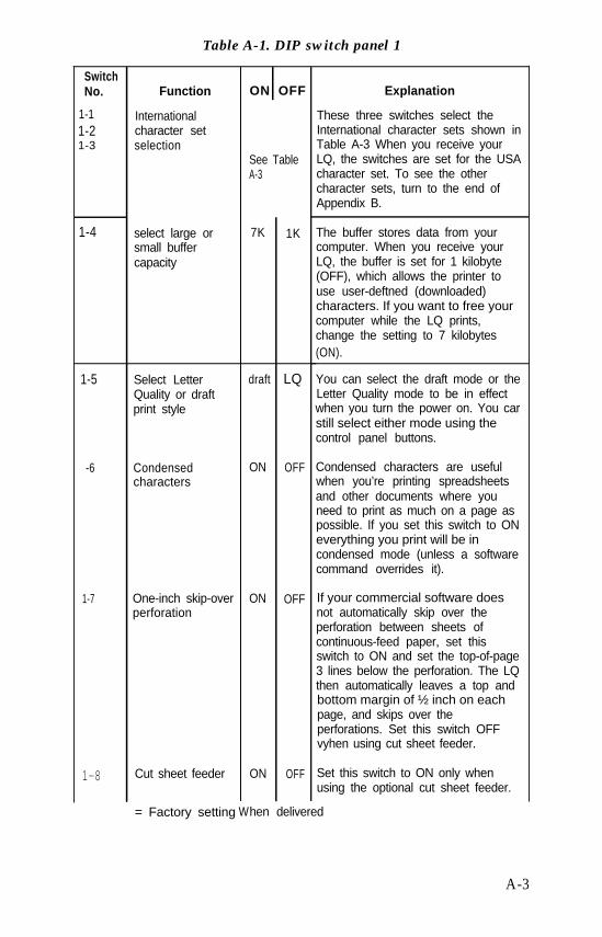
Table A-1. DIP switch panel 1
SwitchNo. ON OFF
See Table
Function Explanation
These three switches select theInternational character sets shown inTable A-3 When you receive yourLQ, the switches are set for the USAcharacter set. To see the othercharacter sets, turn to the end ofAppendix B.
1-1 International1-2 character set1-3 selection
A-3
7K 1K1-4 select large orsmall buffercapacity
The buffer stores data from yourcomputer. When you receive yourLQ, the buffer is set for 1 kilobyte(OFF), which allows the printer touse user-deftned (downloaded)characters. If you want to free yourcomputer while the LQ prints,change the setting to 7 kilobytes(ON).
LQ You can select the draft mode or theLetter Quality mode to be in effectwhen you turn the power on. You carstill select either mode using thecontrol panel buttons.
1-5 Select LetterQuality or draftprint style
draft
-6
1-7
ON OFF Condensed characters are usefulwhen you’re printing spreadsheetsand other documents where youneed to print as much on a page aspossible. If you set this switch to ONeverything you print will be incondensed mode (unless a softwarecommand overrides it).
Condensedcharacters
One-inch skip-overperforation
ON OFF If your commercial software doesnot automatically skip over theperforation between sheets ofcontinuous-feed paper, set thisswitch to ON and set the top-of-page3 lines below the perforation. The LQthen automatically leaves a top andbottom margin of ½ inch on eachpage, and skips over theperforations. Set this switch OFFvyhen using cut sheet feeder.
Cut sheet feeder ON OFF Set this switch to ON only whenusing the optional cut sheet feeder.
= Factory setting When delivered
1-8
A-3
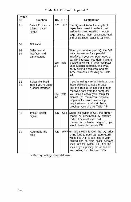
Table A-2. DIP switch panel 2
SwitchNo. Function ON OFF Explanation
2-1 Select 11 -inch or 12” 1 1 ” The LQ must know the length of12-inch paper paper being used in order to skiplength perforations and establish top-of-
page setting. Most continuous-feedand single-sheet paper is 11 inch.
2-2 Not used
2-32-4
Select serialinterface andparity setting
When you receive your LQ, the DIPswitches are set for a parallelinterface. If your computer uses aparallel interface, you don’t have to
See Table change anything. If your computerA-4 uses a serial interface, find what
parity setting it requires, and setthese switches according to TableA-4.
2-52-6
Select the baud If you’re using a serial interface, userate if you’re using these switches to set the bauda serial interface rate-the rate at which the printer
receives data from the computerSee Table You should check your computerA-5 manual (or commercial software
program) for baud rate settingrequirements, and set theseswitches according to Table A-5.
2-7 Printer selectsignal
ON OFF When this switch is ON, the printercannot be deactivated by softwarecodes. For most uses andcommercial software programs, youshould leave this switch ON.
2-8 Automatic linefeed
ON OFF When this switch is ON, the LQ addsa line feed to each carriage return;when it is OFF: it does not. If yourprinting has an extra space betweenlines, turn the switch OFF. If all thelines of your printing are on top ofeach other, turn the switch ON.
= Factory setting when delivered
A-4
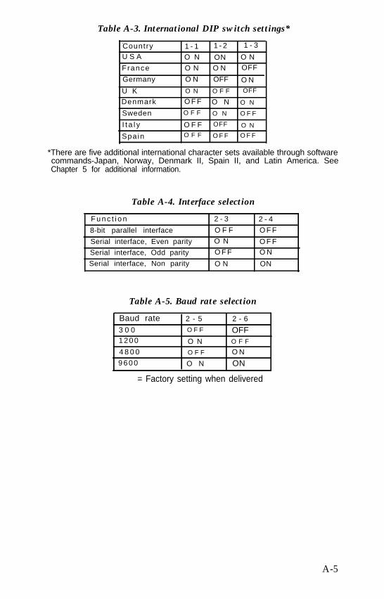
Table A-3. International DIP switch settings*
Country 1 - 1 1 - 2 1 - 3
U S A O N ON O N
France O N O N OFF
Germany O N OFF O N
U K O N O F F OFF
Denmark O F F O N O N
Sweden O F F O N O F F
I t a l y O F F OFF O N
Spain O F F O F F O F F
*There are five additional international character sets available through softwarecommands-Japan, Norway, Denmark II, Spain II, and Latin America. SeeChapter 5 for additional information.
Table A-4. Interface selection
F u n c t i o n 2 - 3 2 - 4
8-bit parallel interface O F F O F F
Serial interface, Even parity O N O F F
Serial interface, Odd parity O F F O N
Serial interface, Non parity O N ON
Table A-5. Baud rate selection
Baud rate 2 - 5 2 - 6
3 0 0 O F F OFF1 2 0 0 O N O F F
4 8 0 0 O F F O N
9 6 0 0 O N ON
= Factory setting when delivered
A-5
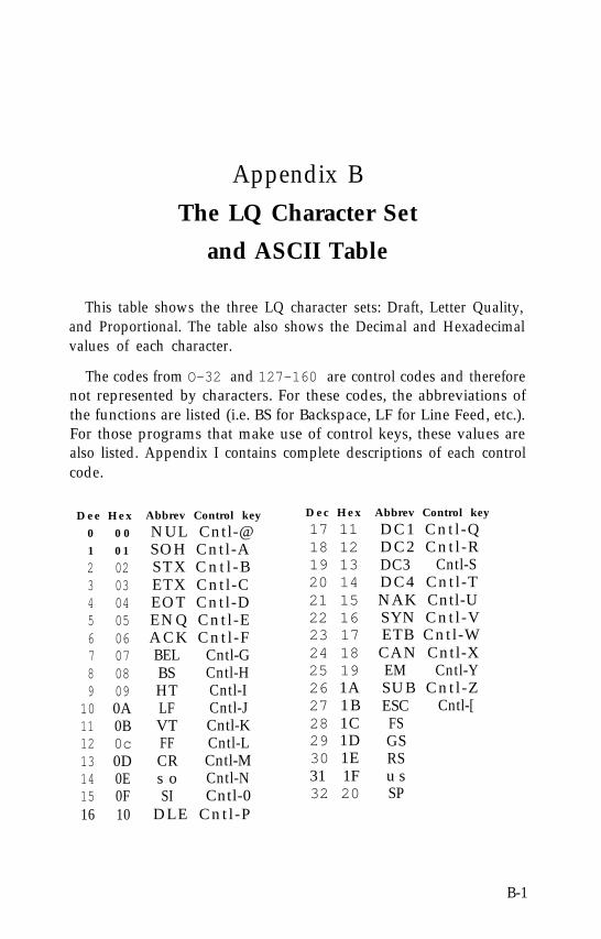
Appendix BThe LQ Character Set
and ASCII Table
This table shows the three LQ character sets: Draft, Letter Quality,and Proportional. The table also shows the Decimal and Hexadecimalvalues of each character.
The codes from O-32 and 127-160 are control codes and thereforenot represented by characters. For these codes, the abbreviations ofthe functions are listed (i.e. BS for Backspace, LF for Line Feed, etc.).For those programs that make use of control keys, these values arealso listed. Appendix I contains complete descriptions of each controlcode.
Dee Hex Abbrev Control key
0 0 0 NUL Cntl-@1 0 1 SOH Cntl-A2 02 STX Cnt l -B3 03 ETX Cntl-C4 04 EOT Cntl-D5 05 ENQ Cntl-E6 06 ACK Cntl-F7 07 BEL Cntl-G8 08 BS Cntl-H9 09 HT Cntl-I10 0A LF Cntl-J11 0B VT Cntl-K12 0c FF Cntl-L13 0D CR Cntl-M14 0E s o Cntl-N15 0F SI Cntl-016 10 DLE Cntl-P
Dec Hex Abbrev Control key
17 11 DC1 Cntl-Q18 12 DC2 Cntl-R19 13 DC3 Cntl-S20 14 DC4 Cntl-T21 15 NAK Cntl-U22 16 SYN Cntl-V23 17 ETB Cntl-W24 18 CAN Cntl-X25 19 EM Cntl-Y26 1A SUB Cntl-Z27 1B ESC Cntl-[28 1C FS29 1D GS30 1E RS31 1F u s32 20 SP
B-1
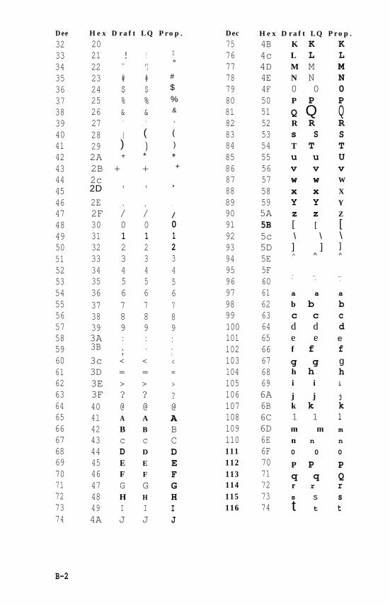
Dee
32333435363738394041424344454647484950515253545556575859606162636465666768697071727374
#
$%&
,
()
*+
'
B-2
H e x D r a f t L Q P r o p .
2021 ! !22 aa "I23 # #24 $ $25 % %26 & &27 ' '28 ( (29 ) )2A * *
2B + +2c2D ' '
2E . .2F / /30 0 031 1 132 2 233 3 334 4 435 5 536 6 637 7 738 8 839 9 93A : :3B .;3c < <3D = =3E > >3F ? ?40 @ @41 A A
42 B B43 c c44 D D
45 E E46 F F
47 G G48 H H
49 I I4A J J
I"
.
/
0123456789...,<=>?@ABCDEFGHIJ
Dec
75767778798081828384858687888990919293949596979899100101102103104105106107108109110111112113114115116
H e x D r a f t L Q P r o p .4B4c4D4E4F505152535455565758595A5B5c5D5E5F606162636465666768696A6B6C6D6E6F7071727374
K K KL L LM M MN N N0 0 0P P PQ Q QR R Rs S ST T Tu u Uv v vw w W
x x X
Y Y Y
z z Z[ [
\ \] ]^ ^
_ _
' '
a a
b bc cd de ef fg gh hi ij jk k1 1m mn n
0 0
P Pq qr r
s
tst
[\]^
_'
a
bcdefghi
j
klm
n
0
PQrst
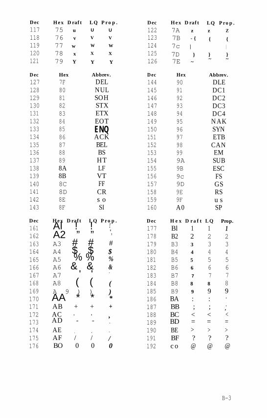
Dec Hex Draft L Q P r o p . Dec Hex Draft117 75 u U U 122 7A z118 76 v V V 123 7B - {119 77 w W W 124 7c |120 78 x X X 125 7D }121 79 Y Y Y 126 7E ~
L Q P r o p .z Z
{ {|
} }~ ~
Dec Hex Abbrev. Dec Hex Abbrev.127 7F DEL 144 90 DLE128 80 NUL 145 91 DC1129 81 SOH 146 92 DC2130 82 STX 147 93 DC3131 83 ETX 148 94 DC4132 84 EOT 149 95 NAK133 85 ENQ 150 96 SYN134 86 ACK 151 97 ETB135 87 BEL 152 98 CAN136 88 BS 153 99 EM137 89 HT 154 9A SUB138 8A LF 155 9B ESC139 8B VT 156 9c FS140 8C FF 157 9D GS141 8D CR 158 9E RS142 8E s o 159 9F u s143 8F SI 160 A0 SP
Dec
161162163164165166167168169170171172173174175176
Hex Draft L Q P r o p .Al ! !A2 ” ”A3 # #A4 $ $A5 % %A6 & &A7 ' 'A8 ( (A 9 ) )AA * *AB + +ACAD - -
' '
AE . .AF / /BO 0 0
!",
#$%&'
()*+,-
.
/0
Dec H e x D r a f t L Q
177 Bl 1 1178 B2 2 2179 B3 3 3180 B4 4 4181 B5 5 5182 B6 6 6183 B7 7 7184 B8 8 8
185 B9 9 9186 BA : :187 BB ; ;188 BC < <189 BD = =190 BE > >191 BF ? ?192 c o @ @
Prop.
123456789..,<=>?@
B-3
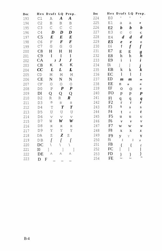
Dec
193194195196197198199200201202203204205206207208209210211212213214215216217218219220221222223
H e x D r a f t L Q P r o p .
Cl A A AC2 B B BC3 C C CC4 D D DC5 E E EC6 F F FC7 G G GC8 H H HC9 I I ICA J J JCB K K KCC L LL LCD M M MCE N N NCF O O OD0 P P PDl Q Q QD2 R R RD3 s s sD4 T T TD5 U U UD6 v v vD7 W W WD8 x x xD9 Y Y YDA Z Z ZDB [ [ [DC \ \ \DD ] ] ]DE ^ ^ ^D F _ _ _
Dec
224225226227228229230231232233234235236237238239240241242243244245246247248249250251252253254
H e x D r a f t L Q P r o p .
E0 ' 'E1 a aE2 b bE3 c cE4 d dE5 e eE6 fE7 g g
f
E8 h hE9 i iEA j jEB k kEC l lED m mEE n n
EF O OFO p pFl q qF2 r rF3 s S
F4 t t
F5 u uF6 V V
F7 w wF8 x xF9 y YFA z zFB { {FC | |FD } }FE ~ ~
,
a
bC
de
fghijk1m
n
0
PqrS
tU
V
W
X
Yz
{
|}~
B-4
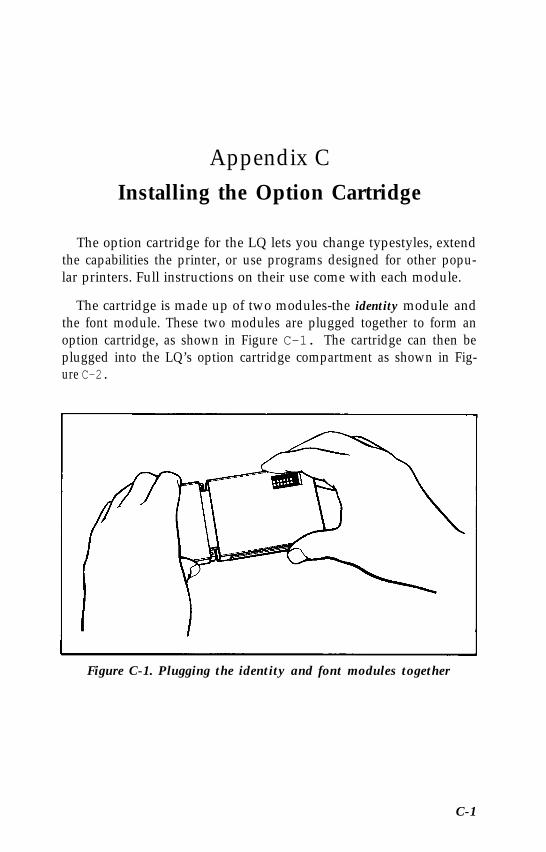
Appendix CInstalling the Option Cartridge
The option cartridge for the LQ lets you change typestyles, extendthe capabilities the printer, or use programs designed for other popu-lar printers. Full instructions on their use come with each module.
The cartridge is made up of two modules-the identity module andthe font module. These two modules are plugged together to form anoption cartridge, as shown in Figure C-1. The cartridge can then beplugged into the LQ’s option cartridge compartment as shown in Fig-ure C-2.
Figure C-1. Plugging the identity and font modules together
C-1
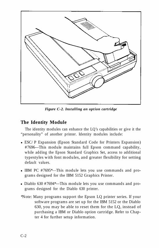
Figure C-2. Installing an option cartridge
The Identity ModuleThe identity modules can enhance the LQ’s capabilities or give it the
“personality” of another printer. Identity modules include:
l ESC/P Expansion (Epson Standard Code for Printers Expansion)#7696—This module maintains full Epson command capability,while adding the Epson Standard Graphics Set, access to additionaltypestyles with font modules, and greater flexibility for settingdefault values.
l IBM PC #7695*—This module lets you use commands and pro-grams designed for the IBM 5152 Graphics Printer.
l Diablo 630 #7694*—This module lets you use commands and pro-grams designed for the Diablo 630 printer.
*Note: Many programs support the Epson LQ printer series. If yoursoftware programs are set up for the IBM 5152 or the Diablo630, you may be able to reset them for the LQ, instead ofpurchasing a IBM or Diablo option cartridge. Refer to Chap-ter 4 for further setup information.
C-2
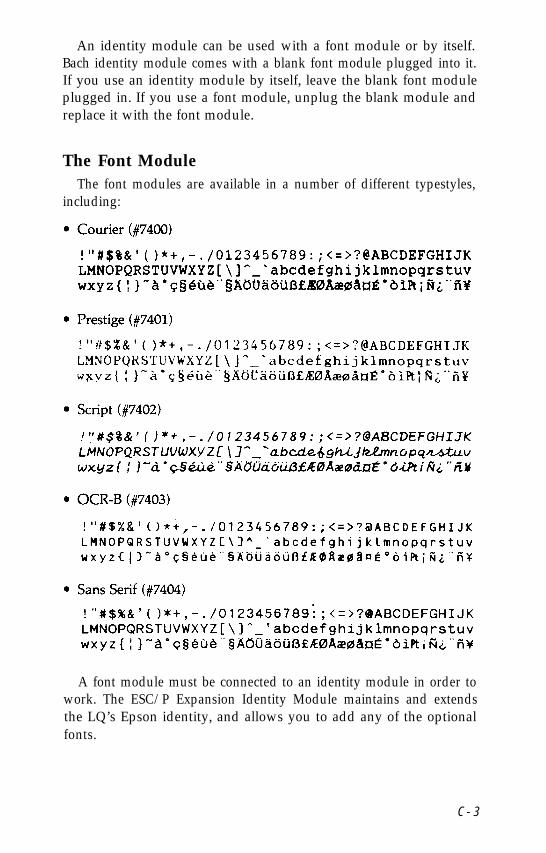
An identity module can be used with a font module or by itself.Bach identity module comes with a blank font module plugged into it.If you use an identity module by itself, leave the blank font moduleplugged in. If you use a font module, unplug the blank module andreplace it with the font module.
The Font ModuleThe font modules are available in a number of different typestyles,
including:
A font module must be connected to an identity module in order towork. The ESC/P Expansion Identity Module maintains and extendsthe LQ’s Epson identity, and allows you to add any of the optionalfonts.
C - 3
Using the Option CartridgesWhen installing an option cartridge, you must turn the power OFF,
plug in the cartridge, then turn the power ON again so that the printeracknowledges that an option cartridge has been installed.
WARNING
Do not install or remove an option cartridge while the poweris ON, because you may damage the printer. Always turn thepower OFF when installing or removing an option cartridge.
With the cartridge installed, the printer reacts to the command setcontained in the identity module. (For specific information on com-mands, see the instructions packaged with the identity module). Toreturn to the LQ’s built-in command set, turn the power OFF removethe cartridge and turn the power ON again.
For typestyle selection, the identity module may have a DIP switchthat allows you to choose which typestyle will be in effect when youturn on the printer-either the LQ’s built-in typestyle, or the fontmodule typestyle.
Whichever default typestyle you select, you can still switchbetween the LQ’s built-in typestyle and the font module typestyle byusing the control panel buttons or ESCape codes. See the instructionspackaged with the option cartridges for further information on theDIP switches and font selection commands.
C-4
Appendix DTroubleshooting and Maintenance
This appendix presents solutions for possible problems, explana-tions of the LQ’s advanced features, and maintenance tips.
Diagnosing the ProblemIf the printouts from your LQ are not matching the document
you’ve prepared on your computer, you’ll need to set up a test docu-ment.
When you set up a test document on your computer, include thesymbols #, [, \, ], and {, because of their variation in the differentcharacter sets. Also include numbers, punctuation marks, symbols,carriage returns, and upper and lower case letters.
Now print the document. First check page B-4 to see whether theLQ is printing the correct character set. When delivered, the LQ is setto print the USA character set. If it’s not printing the USA characterset, determine which character set it is printing. Then consult Appen-dix A on DIP switches to find how to select the correct character set.
If the printout shows other problems, such as one line printing ontop of another, or too much space between lines, consult the followinglist. The statements on the left list possible problems; the recommen-dations are listed on the right.
D-1
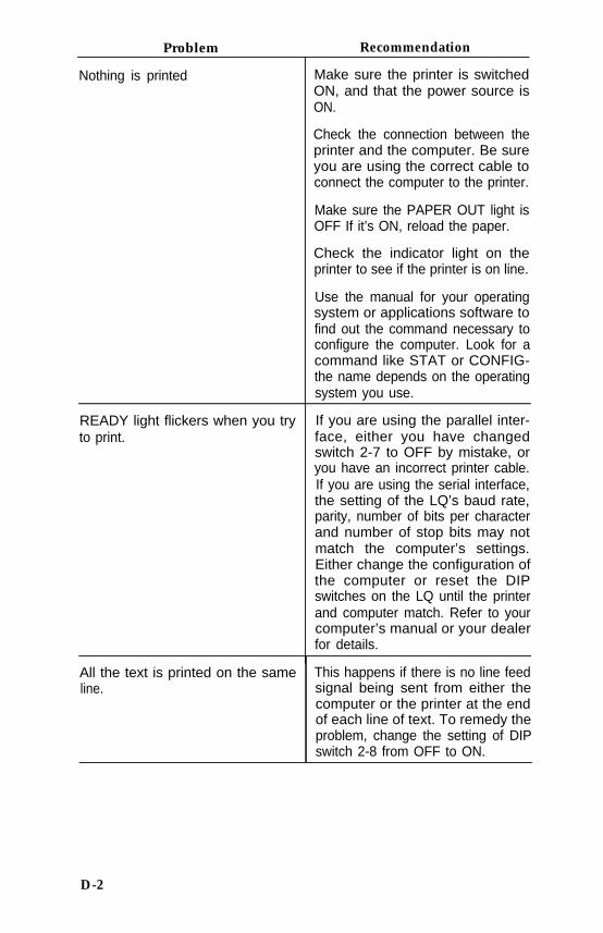
Problem Recommendation
Nothing is printed Make sure the printer is switchedON, and that the power source isON.
Check the connection between theprinter and the computer. Be sureyou are using the correct cable toconnect the computer to the printer.
Make sure the PAPER OUT light isOFF If it’s ON, reload the paper.
Check the indicator light on theprinter to see if the printer is on line.
Use the manual for your operatingsystem or applications software tofind out the command necessary toconfigure the computer. Look for acommand like STAT or CONFIG-the name depends on the operatingsystem you use.
READY light flickers when you tryto print.
All the text is printed on the sameline.
If you are using the parallel inter-face, either you have changedswitch 2-7 to OFF by mistake, oryou have an incorrect printer cable.If you are using the serial interface,the setting of the LQ’s baud rate,parity, number of bits per characterand number of stop bits may notmatch the computer’s settings.Either change the configuration ofthe computer or reset the DIPswitches on the LQ until the printerand computer match. Refer to yourcomputer’s manual or your dealerfor details.
This happens if there is no line feedsignal being sent from either thecomputer or the printer at the endof each line of text. To remedy theproblem, change the setting of DIPswitch 2-8 from OFF to ON.
D-2
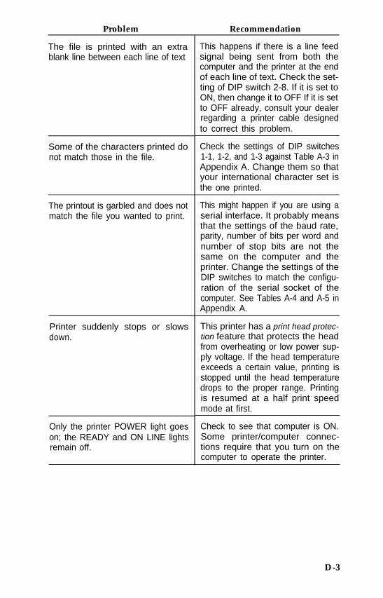
Problem Recommendation
The file is printed with an extrablank line between each line of text
Some of the characters printed donot match those in the file.
This happens if there is a line feedsignal being sent from both thecomputer and the printer at the endof each line of text. Check the set-ting of DIP switch 2-8. If it is set toON, then change it to OFF If it is setto OFF already, consult your dealerregarding a printer cable designedto correct this problem.
Check the settings of DIP switches1-1, 1-2, and 1-3 against Table A-3 inAppendix A. Change them so thatyour international character set isthe one printed.
The printout is garbled and does notmatch the file you wanted to print.
This might happen if you are using aserial interface. It probably meansthat the settings of the baud rate,parity, number of bits per word andnumber of stop bits are not thesame on the computer and theprinter. Change the settings of theDIP switches to match the configu-ration of the serial socket of thecomputer. See Tables A-4 and A-5 inAppendix A.
Printer suddenly stops or slowsdown.
Only the printer POWER light goeson; the READY and ON LINE lightsremain off.
This printer has a print head protec-tion feature that protects the headfrom overheating or low power sup-ply voltage. If the head temperatureexceeds a certain value, printing isstopped until the head temperaturedrops to the proper range. Printingis resumed at a half print speedmode at first.
Check to see that computer is ON.Some printer/computer connec-tions require that you turn on thecomputer to operate the printer.
D-3
Trying again
After you have checked the troubleshooting list, turn the printerOFF then back ON again to register any new settings of DIP switches.Then try printing your test file again. If the file still doesn’t print prop-erly, work through the problems again, changing the settings as neces-sary.
If a further attempt at printing your test file is unsuccessful, contactyour Epson dealer.
Beeper Error WarningsWhen the beeper on the LQ sounds, it usually indicates that the
printer is out of paper. The beeper can also be sounded by a programthat sends ASCII code 7 and by certain error conditions in the printeritself.
If the printer beeps and stops printing when it is not out of paper,turn the printer off and check to see if the paper is loaded correctly. Ifthe paper is loaded correctly, turn the printer back on and try to printagain. If the printer beeps and does not print again, take it to aqualified service person.
Hex Dump ModeThe LQ has a special feature that makes it easy for experienced
printer users to find the causes of problems. The hexadecimal (hex)dump mode gives a printout of exactly what codes reach the printer.
Enter this mode by turning on the power switch on the left side ofthe printer while holding down the FORM FEED and LINE FEED but-tons at the same time. Then, when you run a program, either an appli-cations program or one you have written in any programminglanguage, the LQ prints one or more lines.
Each line has two parts: the hexadecimal codes (up to 16 numbers),and the guide section (16 characters at the end of each line except thelast). The hexadecimal numbers are the codes received by the printer,and the guide section helps you find a certain place in the list of codes.
Each character in the guide section corresponds to one of the codes.If the code is for a printable character, that character is printed. If thecode is for a non-printable character, such as the ESCape code or thecode for a line feed or carriage return, a dot is printed.
D-4
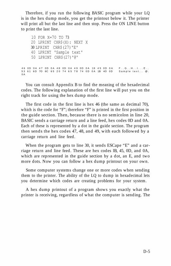
Therefore, if you run the following BASIC program while your LQis in the hex dump mode, you get the printout below it. The printerwill print all but the last line and then stop. Press the ON LINE buttonto print the last line.
l0 FOR X=70 TO 7320 LPRINT CHR$(X): NEXT X30 LPRINT CHR$(27)"E"40 LPRINT "Sample text"50 LPRINT CHR$(27)"@"
4 6 0 D 0 A 4 7 0 D 0 A 4 8 0 D 0 A 4 9 0 D 0 A 1 8 4 5 0 D 0 A F . . G . . H . . I . . . E . .5 3 6 1 6 D 7O 6C 6 5 2 0 7 4 6 5 7 8 7 4 0 D 0 A 1B 4O 0 D S a m p l e t e x t . . . @ .0 A
You can consult Appendix B to find the meaning of the hexadecimalcodes. The following explanation of the first line will put you on theright track for using the hex dump mode.
The first code in the first line is hex 46 (the same as decimal 70),which is the code for “F”; therefore “F” is printed in the first position inthe guide section. Then, because there is no semicolon in line 20,BASIC sends a carriage return and a line feed, hex codes 0D and 0A.Each of these is represented by a dot in the guide section. The programthen sends the hex codes 47, 48, and 49, with each followed by acarriage return and line feed.
When the program gets to line 30, it sends ESCape “E” and a car-riage return and line feed. These are hex codes lB, 45, 0D, and 0A,which are represented in the guide section by a dot, an E, and twomore dots. Now you can follow a hex dump printout on your own.
Some computer systems change one or more codes when sendingthem to the printer. The ability of the LQ to dump in hexadecimal letsyou determine which codes are creating problems for your system.
A hex dump printout of a program shows you exactly what theprinter is receiving, regardless of what the computer is sending. The
D-5
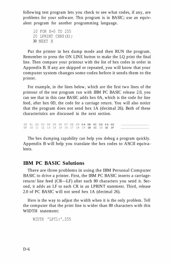
following test program lets you check to see what codes, if any, areproblems for your software. This program is in BASIC; use an equiv-alent program for another programming language.
l0 FOR X=0 TO 25520 LPRINT CHR$(X);30 NEXT X
Put the printer in hex dump mode and then RUN the program.Remember to press the ON LINE button to make the LQ print the finalline. Then compare your printout with the list of hex codes in order inAppendix B. If any are skipped or repeated, you will know that yourcomputer system changes some codes before it sends them to theprinter.
For example, in the lines below, which are the first two lines of theprintout of the test program run with IBM PC BASIC release 2.0, youcan see that in this case BASIC adds hex 0A, which is the code for linefeed, after hex 0D, the code for a carriage return. You will also noticethat the program does not send hex 1A (decimal 26). Both of thesecharacteristics are discussed in the next section.
00 01 02 03 04 05 06 07 08 09 0 A 0B 0C 0 D 0 A 0 E ...............................................0F 10 11 12 13 14 15 16 17 18 19 1B 1C 1D 1E 1F ................................................
The hex dumping capability can help you debug a program quickly.Appendix B will help you translate the hex codes to ASCII equiva-lents.
IBM PC BASIC SolutionsThere are three problems in using the IBM Personal Computer
BASIC to drive a printer. First, the IBM PC BASIC inserts a carriage-return/line feed (CR—LF) after each 80 characters you send it. Sec-ond, it adds an LF to each CR in an LPRINT statement. Third, release2.0 of PC BASIC will not send hex 1A (decimal 26).
Here is the way to adjust the width when it is the only problem. Tellthe computer that the print line is wider than 80 characters with thisWIDTH statement:
WIDTH "LPT1:",255
D-6
The 255 is a special number that prevents the computer system frominserting a CR - LF into the line. Unless, of course, there’s one in yourprogram.
The extra line feed—CHR$(10)—that accompanies each carriagereturn—CHR$(13)—is no problem except when you need to useCHR$(13) in a graphics program. Getting rid of the extra CHR$(10) israther complicated. First you open the printer as a random file:
OPEN "LPTl:" AS #l
Although this allows you to send any code to the printer, you can nolonger use the LPRINT command. Instead, you must use a PRINT #1command:
PRINT #1, "Now I can print anything"
This does allow you to print anything, but it ignores any previousWIDTH statements.
If you want to print more than 80 columns per line in a graphicsprogram, you must therefore change your opening statement toinclude the appropriate WIDTH statement:
OPEN "LPTl:" AS #l : WIDTH #l, 255
There is no easy solution to the problem with CHR$(26). It is best tochange any instance of decimal 26 (hex 1A) in your programs toanother number.
Applesoft BASIC SolutionsApplesoft BASIC does not use PRINT to send data to the screen
and LPRINT to send data to the printer as Microsoft BASIC does.Therefore, you need to change the programs in this manual some-what. In most cases all you need to do is to add two lines to eachprogram and change all instances of LPRINT to PRINT. Add a line atthe beginning of the program that states PR#l and a line at the endthat states PR#0.
For the programs in this manual that contain INPUT statements,put the line that states PR#l after the INPUT statement.
D-7
QX-10® and QX-16 SolutionsThe format for the WIDTH statement for the Epson QX-10 and
QX-16 computers is:
WIDTH LPRINT 255
MaintenanceTo keep your LQ working like new, always keep it in a safe and
clean place. Keep it away from dust, grease, and any heat sources. Asafe temperature range is 41°F to 95°F.
To clean the outside of the printer case, use a soft, clean cloth damp-ened with clear water. Stubborn stains can be removed with non-abrasive household cleaners.
The inside front portion of the printer should also be cleaned peri-odically to get rid of dust and paper lint. First, turn the power switchOFF and unplug the power cord from the electrical outlet. Thenremove the dust cover.
Use a small vacuum cleaner and soft brush to clean inside theprinter. Be careful not to bend or damage any of the parts inside theprinter. With the power OFF, you can move the print head back andforth to clean under it.
Once in a great while your LQ should be lubricated by an autho-rized Epson dealer.
Changing the print head
The expected life of an LQ print head is about 200 million strokes.See your Epson dealer for replacements. If the print head fails sud-denly or long before its estimated lifetime is over, the problem is prob-ably in another component of the printer. Take the LQ to your dealerfor service.
Removing the old print head
Be sure the power is OFF before you touch the print head. If youhave been printing, wait about 15 minutes to allow the print head tocool.
D-8
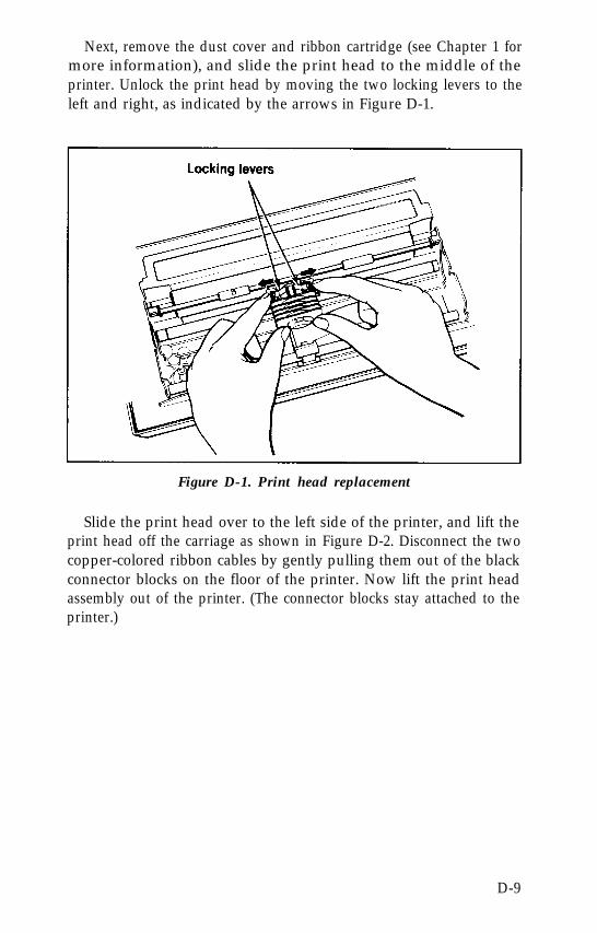
Next, remove the dust cover and ribbon cartridge (see Chapter 1 formore information), and slide the print head to the middle of theprinter. Unlock the print head by moving the two locking levers to theleft and right, as indicated by the arrows in Figure D-1.
Figure D-1. Print head replacement
Slide the print head over to the left side of the printer, and lift theprint head off the carriage as shown in Figure D-2. Disconnect the twocopper-colored ribbon cables by gently pulling them out of the blackconnector blocks on the floor of the printer. Now lift the print headassembly out of the printer. (The connector blocks stay attached to theprinter.)
D-9
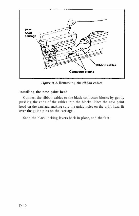
Figure D-2. Removing the ribbon cables
Installing the new print head
Connect the ribbon cables to the black connector blocks by gentlypushing the ends of the cables into the blocks. Place the new printhead on the carriage, making sure the guide holes on the print head fitover the guide pins on the carriage.
Snap the black locking levers back in place, and that’s it.
D-10
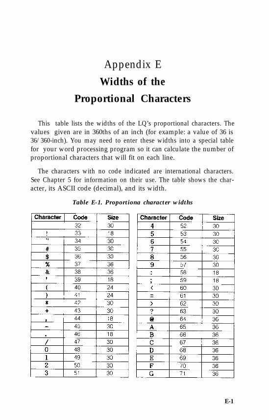
Appendix EWidths of the
Proportional Characters
This table lists the widths of the LQ’s proportional characters. Thevalues given are in 360ths of an inch (for example: a value of 36 is36/360-inch). You may need to enter these widths into a special tablefor your word processing program so it can calculate the number ofproportional characters that will fit on each line.
The characters with no code indicated are international characters.See Chapter 5 for information on their use. The table shows the char-acter, its ASCII code (decimal), and its width.
Table E-1. Proportiona character widths
E-1
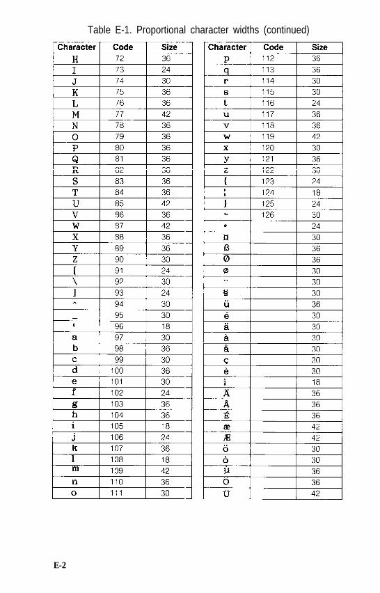
Table E-1. Proportional character widths (continued)
E-2
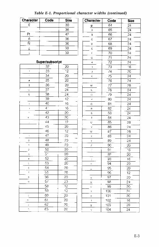
Table E-1. Proportional character widths (continued)
E-3
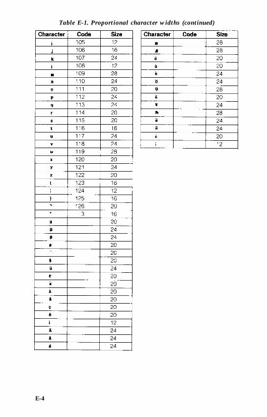
Table E-1. Proportional character widths (continued)
E-4
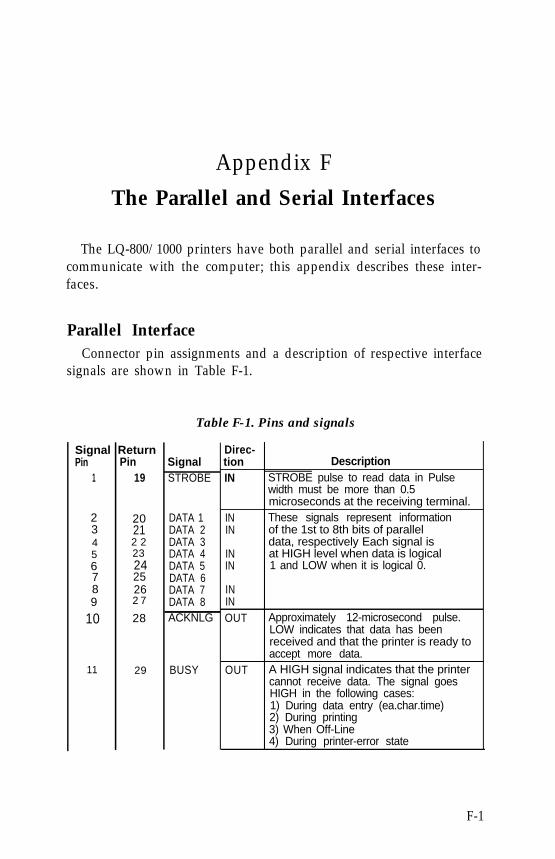
Appendix FThe Parallel and Serial Interfaces
The LQ-800/1000 printers have both parallel and serial interfaces tocommunicate with the computer; this appendix describes these inter-faces.
Parallel InterfaceConnector pin assignments and a description of respective interface
signals are shown in Table F-1.
Table F-1. Pins and signals
Signal ReturnPin Pin
1 19
2 203 214 2 25 236 247 258 269 2 7
10 28
11 29
SignalSTROBE
DATA 1DATA 2DATA 3DATA 4DATA 5DATA 6DATA 7DATA 8ACKNLG
BUSY
Direc-tion DescriptionIN STROBE pulse to read data in Pulse
width must be more than 0.5microseconds at the receiving terminal.
IN These signals represent informationIN of the 1st to 8th bits of parallel
INdata, respectively Each signal isat HIGH level when data is logical
IN 1 and LOW when it is logical 0.
ININOUT Approximately 12-microsecond pulse.
LOW indicates that data has beenreceived and that the printer is ready toaccept more data.
OUT A HIGH signal indicates that the printercannot receive data. The signal goesHIGH in the following cases:1) During data entry (ea.char.time)2) During printing3) When Off-Line4) During printer-error state
F-1
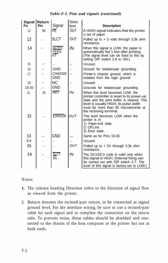
Table F-1. Pins and signals (continued)
Signal Return Direc-Pin Pin Signal tion
12 30 PE OUT
13 — SLCT OUT
14 — AUTO INFEEDXT
DescriptionA HIGH signal indicates that the printerIS out of paper.
15 — — —
16 — GND —
17 — CHASSIS —
GND18 — NC —
19-30 — GND —
31 16 INIT IN
36 — SLCT- ININ
Notes:
1.
2.
32 — ERROR OUT
33 — GND —3 4 — — —
35 — — OUT
Pulled up to + 5 volts through 3.3k ohmresistance.When this signal is LOW, the paper isautomatically fed 1 line after printing.(The signal level can be fixed to this bysetting DIP switch 2-8 to ON.)Unused.Ground for twisted-pair grounding.Printer’s chassis ground, which isisolated from the logic ground.UnusedGrounds for twisted-pair grounding.When this level becomes LOW, theprinter controller is reset to its power-upstate and the print buffer is cleared. Thislevel is usually HIGH, its pulse widthmust be more than 50 microseconds atthe receiving terminal.This level becomes LOW when theprinter is in:1) Paper-end state.2) Off-Line.3) Error state.Same as for Pins 19-30.Unused.Pulled up to + 5V through 3.3k ohmresistance.The DC1/DC3 code is valid only whenthis signal is HIGH. (Internal fixing canbe carried out with DIP switch 2-7. Thelevel of this signal is factory-set to LOW.)
The column heading Direction refers to the direction of signal flowas viewed from the printer.
Return denotes the twisted-pair return, to be connected at signalground level. For the interface wiring, be sure to use a twisted-paircable for each signal and to complete the connection on the returnside. To prevent noise, these cables should be shielded and con-nected to the chassis of the host computer or the printer but not atboth ends.
F-2
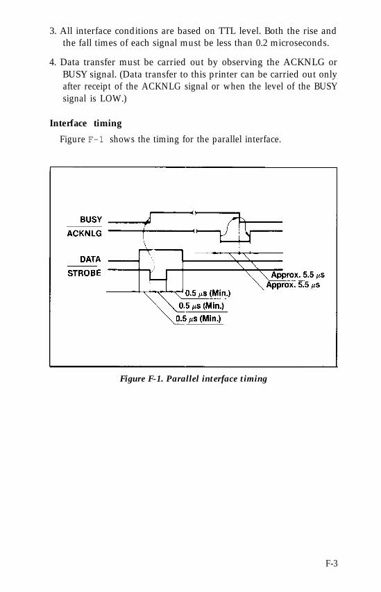
3. All interface conditions are based on TTL level. Both the rise andthe fall times of each signal must be less than 0.2 microseconds.
4. Data transfer must be carried out by observing the ACKNLG orBUSY signal. (Data transfer to this printer can be carried out onlyafter receipt of the ACKNLG signal or when the level of the BUSYsignal is LOW.)
Interface timing
Figure F-1 shows the timing for the parallel interface.
Figure F-1. Parallel interface timing
F-3
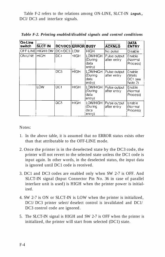
Table F-2 refers to the relations among ON-LINE, SLCT-IN input,DCl/DC3 and interface signals.
Table F-2. Printing enabled/disabled signals and control conditions
Notes:
1. In the above table, it is assumed that no ERROR status exists otherthan that attributable to the OFF-LINE mode.
2. Once the printer is in the deselected state by the DC3 code, theprinter will not revert to the selected state unless the DC1 code isinput again. In other words, in the deselected status, the input datais ignored until DC1 code is received.
3. DC1 and DC3 codes are enabled only when SW 2-7 is OFF. AndSLCT-IN signal (Input Connector Pin No. 36 in case of parallelinterface unit is used) is HIGH when the printer power is initial-ized.
4. SW 2-7 is ON or SLCT-IN is LOW when the printer is initialized,DC1/DC3 printer select/deselect control is invalidated and DC1/DC3 control code are ignored.
5. The SLCT-IN signal is HIGH and SW 2-7 is OFF when the printer isinitialized, the printer will start from selected (DC1) state.
F-4
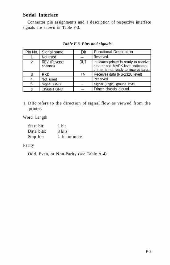
Serial InterfaceConnector pin assignments and a description of respective interface
signals are shown in Table F-3.
Table F-3. Pins and signals
Pin No. Signal name Dir Functional Description1 Not used — Reserved.2 REV (Reverse OUT Indicates printer is ready to receive
channel) data or not. MARK level indicatesprinter is not ready to receive data.
3 RXD I N Receives data (RS-232C level)4 Not used — Reserved.5 Signal GND — Signal (Logic) ground level.
6 Chassis GND — Printer chassis ground.
1. DIR refers to the direction of signal flow as viewed from theprinter.
Word Length
Start bit:Data bits:Stop bit:
Parity
1 bit8 bits1 bit or more
Odd, Even, or Non-Parity (see Table A-4)
F-5
Appendix GChoosing and Setting Up
Optional Interfaces
This appendix summarizes the Epson interfaces compatible with theLQ-800 and LQ-1000 printers and gives instructions for installinginternally mounted interface boards.
Compatible InterfacesYou can use a number of optional interfaces with the LQ-800 and
LQ-1000, which supplement the built-in parallel and serial interfaces.These fall into three categories.
l Serial interfaces, which allow connection to a large range of com-puters without a parallel interface.
l IEEE-488 and other special interfaces, which allow connection tocomputers with other interface requirements (in some cases theseare installed on the computer rather than the printer).
l Buffer interfaces, which provide a larger data buffer to release thecomputer for other tasks when printing large amounts of text.
The following Epson interfaces are compatible with the LQ-800 andLQ-1000 printers, although some of these are no longer available.
#8143#8148#8149#8149M#8161#8165#8172#8172M
serial interfaceintelligent serial interfaceintelligent serial interface Type IIintelligent serial interface Type IIIIEEE-488 interfaceintelligent IEEE-488 interface32K byte buffer parallel interface128K byte buffer parallel interface
G-1
Internally Mounted Interface CardsBefore you can install these you need to take off the upper half of
the printer case to get to the main circuit board.
WARNING
High voltages are present inside the printer when the power isswitched ON. Do not remove the case and install optionalinterfaces unless the printer is switched OFF and the ACpower cord is unplugged from its outlet. Also, beware oftouching contacts on the circuit board of the printer - manyof the components are sensitive to static electricity and can bedestroyed by the charge that may build up on your body.
Removing and replacing the printer case
1. Turn OFF the power to both the printer and the computer, anddisconnect the interface cable from the printer.
2. Remove the dust cover. Take off the paper feed knob on the rightside by pulling it straight out from the printer.
3. Remove the ribbon cartridge.
G-2
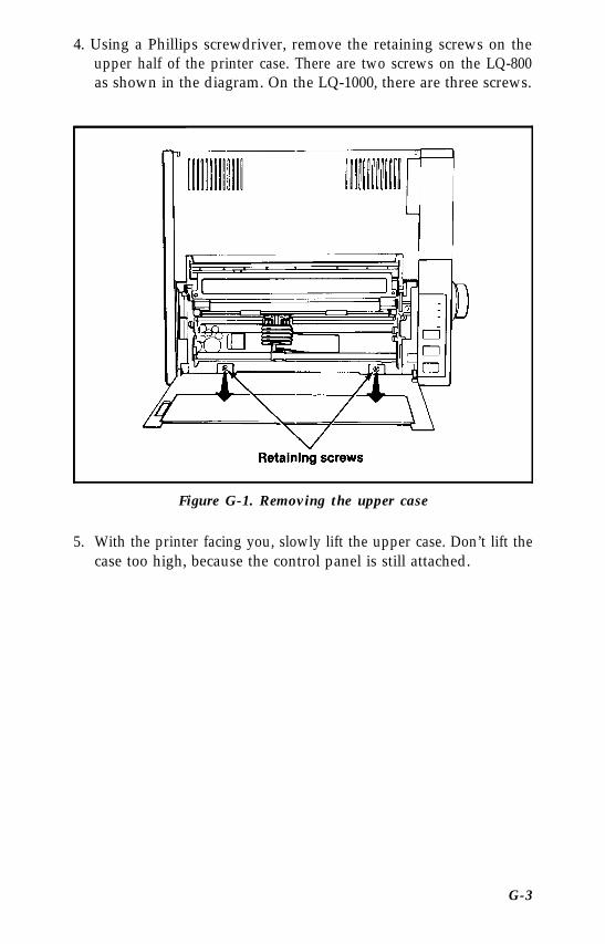
4. Using a Phillips screwdriver, remove the retaining screws on theupper half of the printer case. There are two screws on the LQ-800as shown in the diagram. On the LQ-1000, there are three screws.
Figure G-1. Removing the upper case
5. With the printer facing you, slowly lift the upper case. Don’t lift thecase too high, because the control panel is still attached.
G-3
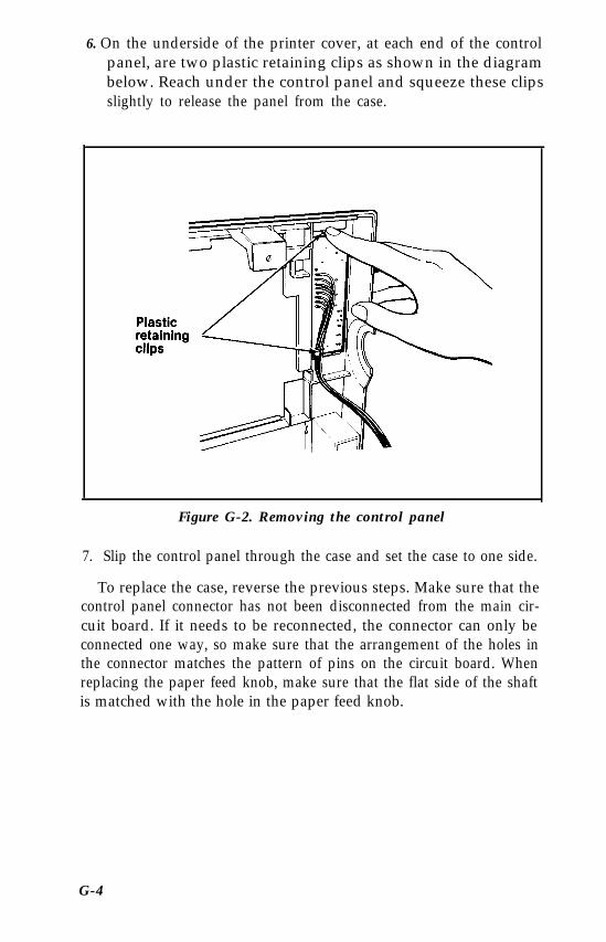
6. On the underside of the printer cover, at each end of the controlpanel, are two plastic retaining clips as shown in the diagrambelow. Reach under the control panel and squeeze these clipsslightly to release the panel from the case.
Figure G-2. Removing the control panel
7. Slip the control panel through the case and set the case to one side.
To replace the case, reverse the previous steps. Make sure that thecontrol panel connector has not been disconnected from the main cir-cuit board. If it needs to be reconnected, the connector can only beconnected one way, so make sure that the arrangement of the holes inthe connector matches the pattern of pins on the circuit board. Whenreplacing the paper feed knob, make sure that the flat side of the shaftis matched with the hole in the paper feed knob.
G-4
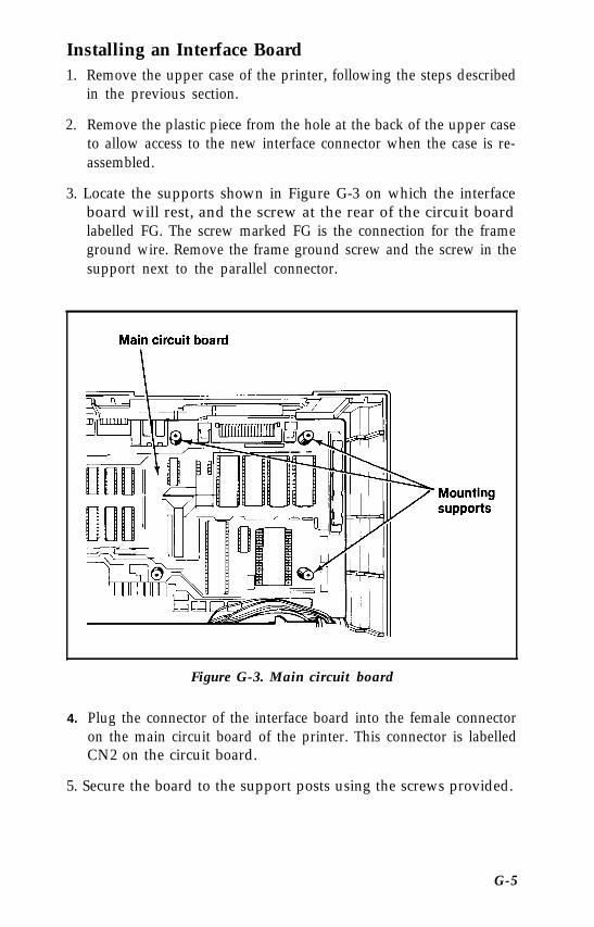
Installing an Interface Board1. Remove the upper case of the printer, following the steps described
in the previous section.
2. Remove the plastic piece from the hole at the back of the upper caseto allow access to the new interface connector when the case is re-assembled.
3. Locate the supports shown in Figure G-3 on which the interfaceboard will rest, and the screw at the rear of the circuit boardlabelled FG. The screw marked FG is the connection for the frameground wire. Remove the frame ground screw and the screw in thesupport next to the parallel connector.
Figure G-3. Main circuit board
4. Plug the connector of the interface board into the female connectoron the main circuit board of the printer. This connector is labelledCN2 on the circuit board.
5. Secure the board to the support posts using the screws provided.
G-5
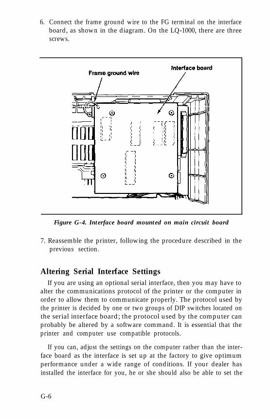
6. Connect the frame ground wire to the FG terminal on the interfaceboard, as shown in the diagram. On the LQ-1000, there are threescrews.
Figure G-4. Interface board mounted on main circuit board
7. Reassemble the printer, following the procedure described in theprevious section.
Altering Serial Interface SettingsIf you are using an optional serial interface, then you may have to
alter the communications protocol of the printer or the computer inorder to allow them to communicate properly. The protocol used bythe printer is decided by one or two groups of DIP switches located onthe serial interface board; the protocol used by the computer canprobably be altered by a software command. It is essential that theprinter and computer use compatible protocols.
If you can, adjust the settings on the computer rather than the inter-face board as the interface is set up at the factory to give optimumperformance under a wide range of conditions. If your dealer hasinstalled the interface for you, he or she should also be able to set the
G-6
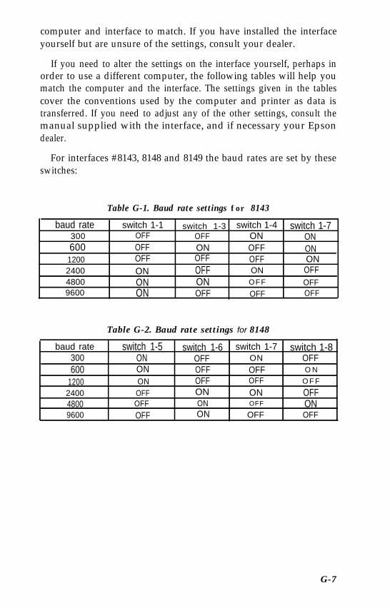
computer and interface to match. If you have installed the interfaceyourself but are unsure of the settings, consult your dealer.
If you need to alter the settings on the interface yourself, perhaps inorder to use a different computer, the following tables will help youmatch the computer and the interface. The settings given in the tablescover the conventions used by the computer and printer as data istransferred. If you need to adjust any of the other settings, consult themanual supplied with the interface, and if necessary your Epsondealer.
For interfaces #8143, 8148 and 8149 the baud rates are set by theseswitches:
Table G-1. Baud rate settings for 8143
baud rate switch 1-1 switch 1-3 switch 1-4 switch 1-7300 OFF OFF ON ON600 OFF ON OFF ON1200 OFF OFF OFF ON2400 ON OFF ON OFF4800 ON ON OFF OFF9600 ON OFF OFF OFF
Table G-2. Baud rate settings for 8148
baud rate switch 1-5 switch 1-6 switch 1-7 switch 1-8300 ON OFF ON OFF600 ON OFF OFF O N
1200 ON OFF OFF O F F
2400 OFF ON ON OFF4800 OFF ON OFF ON9600 OFF ON OFF OFF
G-7
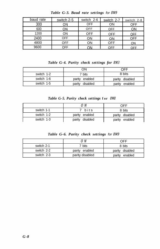
Table G-3. Baud rate settings for 8149
baud rate switch 2-5 switch 2-6 switch 2-7 switch 2-8
300 ON OFF ON OFF600 ON OFF OFF ON
1200 ON OFF OFF OFF2400 OFF ON ON OFF4800 OFF ON OFF ON9600 OFF ON OFF OFF
Table G-4. Parity check settings for 8143
switch 1-2switch 1-6switch 1-5
ON7 bits
parity enabledparity disabled
OFF8 bits
parity disabledparity enabled
Table G-5. Parity check settings for 8148
switch 1-1switch 1-2switch 1-3
O N7 b i t s
parity enabledparity disabled
OFF8 bits
parity disabledparity enabled
Table G-6. Parity check settings for 8149
switch 2-1switch 2-2switch 2-3
O N OFF7 bits 8 bits
panty enabled parity disabledparity disabled parity enabled
G-8
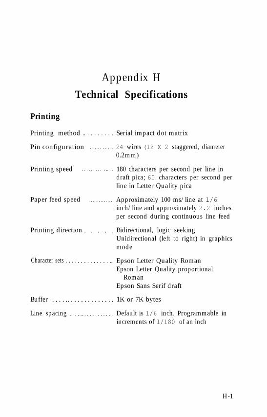
Appendix HTechnical Specifications
Printing
Printing method
Pin configuration
Printing speed
Paper feed speed
Printing direction
Character sets . . . .
Buffer
Line spacing
.. . . . . . . . . Serial impact dot matrix
. . . . . . . . .. 24 wires (12 X 2 staggered, diameter0.2mm)
. . . . . . . . . . .. . . 180 characters per second per line indraft pica; 60 characters per second perline in Letter Quality pica
. . . . .. . . . . . . . . Approximately 100 ms/line at l/6inch/line and approximately 2.2 inchesper second during continuous line feed
. . . . . Bidirectional, logic seekingUnidirectional (left to right) in graphicsmode
. . . . . . . . . . .. Epson Letter Quality RomanEpson Letter Quality proportional
RomanEpson Sans Serif draft
. . . . .. . . . . . . . . . . . . . 1K or 7K bytes
. . . . .. . . . . . . . . . . . Default is l/6 inch. Programmable inincrements of l/180 of an inch
H-1
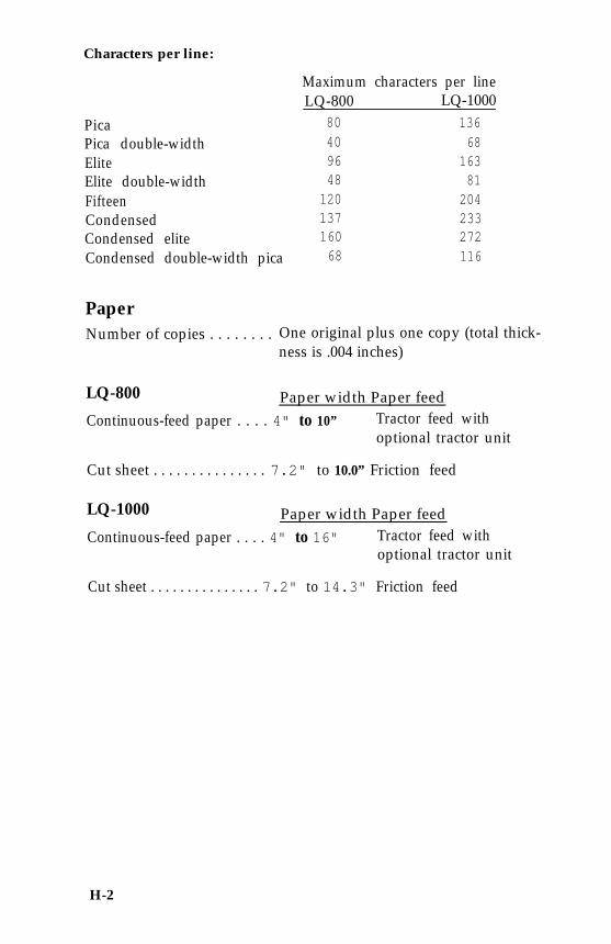
Characters per line:
PicaPica double-widthEliteElite double-widthFifteenCondensedCondensed eliteCondensed double-width pica
Maximum characters per lineLQ-800 LQ-1000
80 13640 6896 16348 81120 204137 233160 27268 116
PaperNumber of copies . . . . . . . . One original plus one copy (total thick-
ness is .004 inches)
LQ-800 Paper width Paper feedContinuous-feed paper . . . . 4" to 10” Tractor feed with
optional tractor unit
Cut sheet . . . . . . . . . . . . . . . 7.2" to 10.0” Friction feed
LQ-1000 Paper width Paper feedContinuous-feed paper . . . . 4" to 16" Tractor feed with
optional tractor unit
Cut sheet . . . . . . . . . . . . . . . 7.2" to 14.3" Friction feed
H-2
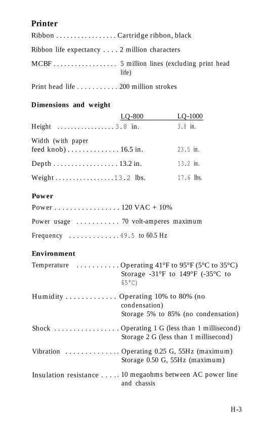
PrinterRibbon . . . . . . . . . . . . . . . . . Cartridge ribbon, black
Ribbon life expectancy . . . . 2 million characters
MCBF . . . . . . . . . . . . . . . . . . 5 million lines (excluding print headlife)
Print head life . . . . . . . . . . . 200 million strokes
Dimensions and weight
LQ-800Height . . . . . . . . . . . . . . . . . 3.8 in.
Width (with paper
LQ-10003.8 in.
feed knob) . . . . . . . . . . . . . . 16.5 in.
Depth . . . . . . . . . . . . . . . . . . 13.2 in.
Weight . . . . . . . . . . . . . . . . . 13.2 lbs.
Power
23.5 in.
13.2 in.
17.6 lbs.
Power . . . . . . . . . . . . . . . . . 120 VAC + 10%
Power usage . . . . . . . . . .
Frequency . . . . . . . . . . . .
Environment
Temperature . . . . . . . . . .
Humidity . . . . . . . . . . . . .
Shock . . . . . . . . . . . . . . . .
Vibration . . . . . . . . . . . . .
Insulation resistance . . . .
. 70 volt-amperes maximum
. 49.5 to 60.5 Hz
. Operating 41°F to 95°F (5°C to 35°C)Storage -31°F to 149°F (-35°C to65°C)
Operating 10% to 80% (nocondensation)Storage 5% to 85% (no condensation)
. Operating 1 G (less than 1 millisecond)Storage 2 G (less than 1 millisecond)
. Operating 0.25 G, 55Hz (maximum)Storage 0.50 G, 55Hz (maximum)
. 10 megaohms between AC power lineand chassis
H-3
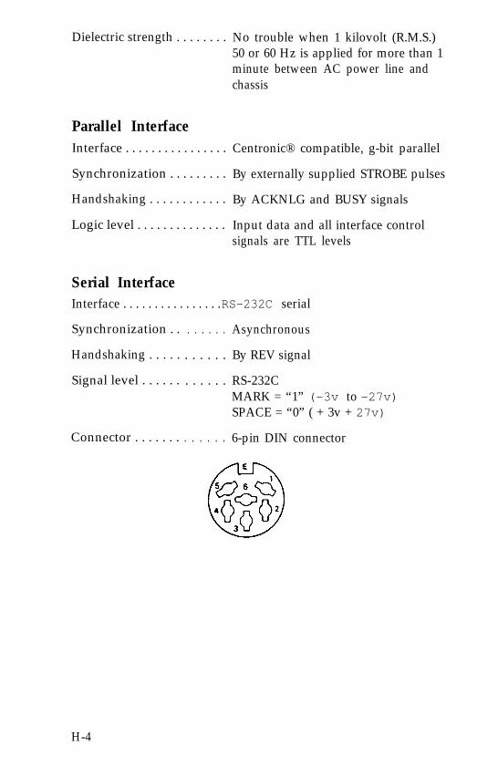
Dielectric strength . . . . . . . . No trouble when 1 kilovolt (R.M.S.)50 or 60 Hz is applied for more than 1minute between AC power line andchassis
Parallel InterfaceInterface . . . . . . . . . . . . . . . . Centronic® compatible, g-bit parallel
Synchronization . . . . . . . . . By externally supplied STROBE pulses
Handshaking . . . . . . . . . . . . By ACKNLG and BUSY signals
Logic level . . . . . . . . . . . . . . Input data and all interface controlsignals are TTL levels
Serial InterfaceInterface . . . . . . . . . . . . . . . . RS-232C serial
Synchronization . .
Handshaking . . . . .
Signal level . . . . . .
Connector . . . . . . .
. . . . . . Asynchronous
. . . . . . By REV signal
. . . . . . RS-232CMARK = “1” (-3v to -27v)SPACE = “0” ( + 3v + 27v)
. . . . . . 6-pin DIN connector
H-4
Appendix ICommand Summary
This appendix lists the default settings of the LQ. It also contains allof the control codes and ESCape sequences used by the LQ. They arefirst listed in numerical order and then by function. Each listing in thenumerical section gives the page in the function section where fullinformation on the command is given. For many of the commandsyou can also consult the index to find out where they are discussed inthe text.
Default SettingsWhen your LQ comes from the factory, it is set to the following
defaults. Defaults are the settings in effect each time the printer isturned on. A dot (•) means that you can change the default for thissetting by changing a DIP switch.
l Pica width
Margins set at maximums: left margin at 0 and right margin at 80 onthe LQ-800 and 136 on the LQ-1000
l/6 of an inch line spacing
Page length of 11 inches
Horizontal tabs set at every eight characters
l USA character set
Top-of-page is set at the position of the print head.
I-1
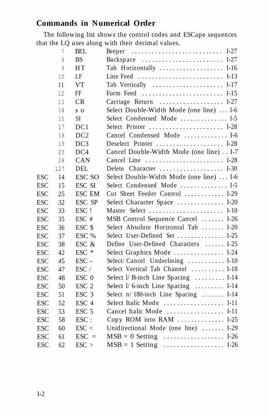
Commands in Numerical OrderThe following list shows the control codes and ESCape sequences
that the LQ uses along with their decimal values.789
1011121314151718192024
127ESC 14ESC 15ESC 25ESC 32ESC 33ESC 35ESC 36ESC 37ESC 38ESC 42ESC 45ESC 47ESC 48ESC 50ESC 51ESC 52ESC 53ESC 58ESC 60ESC 61ESC 62
BELBSHTLFVTFFCRs oSIDC1DC2DC3DC4CANDELESC SOESC SIESC EMESC SPESC !ESC #ESC $ESC %ESC &ESC *ESC -ESC /ESC 0ESC 2ESC 3ESC 4ESC 5ESC :ESC <ESC =ESC >
Beeper . . . . . . . . . . . . . . . . . . . . . . . . . . . I-27Backspace . . . . . . . . . . . . . . . . . . . . . . . . I-27Tab Horizontally . . . . . . . . . . . . . . . . . . . I-16Line Feed . . . . . . . . . . . . . . . . . . . . . . . . . I-13Tab Vertically . . . . . . . . . . . . . . . . . . . . . I-17Form Feed . . . . . . . . . . . . . . . . . . . . . . . . I-15Carriage Return . . . . . . . . . . . . . . . . . . . I-27Select Double-Width Mode (one line) . . . I-6Select Condensed Mode . . . . . . . . . . . . . . I-5Select Printer . . . . . . . . . . . . . . . . . . . . . . I-28Cancel Condensed Mode . . . . . . . . . . . . . I-6Deselect Printer . . . . . . . . . . . . . . . . . . . . I-28Cancel Double-Width Mode (one line) . . I-7Cancel Line . . . . . . . . . . . . . . . . . . . . . . . I-28Delete Character . . . . . . . . . . . . . . . . . . . I-30Select Double-Width Mode (one line) . . . I-6Select Condensed Mode . . . . . . . . . . . . . . I-5Cut Sheet Feeder Control . . . . . . . . . . . . I-29Select Character Space . . . . . . . . . . . . . . I-20Master Select . . . . . . . . . . . . . . . . . . . . . . I-10MSB Control Sequence Cancel . . . . . . . I-26Select Absolute Horizontal Tab . . . . . . . I-20Select User-Defined Set . . . . . . . . . . . . . . I-25Define User-Defined Characters . . . . . . I-25Select Graphics Mode . . . . . . . . . . . . . . . I-24Select/Cancel Underlining . . . . . . . . . . . I-10Select Vertical Tab Channel . . . . . . . . . . I-18Select l/B-inch Line Spacing . . . . . . . . . I-14Select l/6-inch Line Spacing . . . . . . . . . I-14Select n/180-inch Line Spacing . . . . . . . I-14Select Italic Mode . . . . . . . . . . . . . . . . . . I-11Cancel Italic Mode . . . . . . . . . . . . . . . . . I-11Copy ROM into RAM . . . . . . . . . . . . . . I-25Unidirectional Mode (one line) . . . . . . . I-29MSB = 0 Setting . . . . . . . . . . . . . . . . . . I-26MSB = 1 Setting . . . . . . . . . . . . . . . . . . I-26
I-2
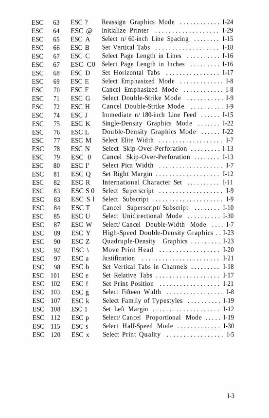
ESC 63ESC 64ESC 65ESC 66ESC 67ESC 67ESC 68ESC 69ESC 70ESC 71ESC 72ESC 74ESC 75ESC 76ESC 77ESC 78ESC 79ESC 80ESC 81ESC 82ESC 83ESC 83ESC 84ESC 85ESC 87ESC 89ESC 90ESC 92ESC 97ESC 98ESC 101ESC 102ESC 103ESC 107ESC 108ESC 112ESC 115ESC 120
ESC ?ESC @ESC AESC BESC CESC C0ESC DESC EESC FESC GESC HESC JESC KESC LESC MESC NESC 0ESC I’ESC QESC RESC S 0ESC S lESC TESC UESC WESC YESC ZESC \ESC aESC bESC eESC fESC gESC kESC 1ESC pESC sESC x
Reassign Graphics Mode . . . . . . . . . . . . I-24Initialize Printer . . . . . . . . . . . . . . . . . . . I-29Select n/60-inch Line Spacing . . . . . . . . I-15Set Vertical Tabs . . . . . . . . . . . . . . . . . . . I-18Select Page Length in Lines . . . . . . . . . . I-16Select Page Length in Inches . . . . . . . . . I-16Set Horizontal Tabs . . . . . . . . . . . . . . . . I-17Select Emphasized Mode . . . . . . . . . . . . . I-8Cancel Emphasized Mode . . . . . . . . . . . . I-8Select Double-Strike Mode . . . . . . . . . . . I-9Cancel Double-Strike Mode . . . . . . . . . . I-9Immediate n/180-inch Line Feed . . . . . . I-15Single-Density Graphics Mode . . . . . . . I-22Double-Density Graphics Mode . . . . . . I-22Select Elite Width . . . . . . . . . . . . . . . . . . . I-7Select Skip-Over-Perforation . . . . . . . . . I-13Cancel Skip-Over-Perforation . . . . . . . . I-13Select Pica Width . . . . . . . . . . . . . . . . . . . I-7Set Right Margin . . . . . . . . . . . . . . . . . . . I-12International Character Set . . . . . . . . . . I-11Select Superscript . . . . . . . . . . . . . . . . . . . I-9Select Subscript . . . . . . . . . . . . . . . . . . . . . I-9Cancel Superscript/Subscript . . . . . . . . I-10Select Unidirectional Mode . . . . . . . . . . I-30Select/Cancel Double-Width Mode . . . . I-7High-Speed Double-Density Graphics . . I-23Quadruple-Density Graphics . . . . . . . . . I-23Move Print Head . . . . . . . . . . . . . . . . . . I-20Justification . . . . . . . . . . . . . . . . . . . . . . . I-21Set Vertical Tabs in Channels . . . . . . . . . I-18Set Relative Tabs . . . . . . . . . . . . . . . . . . . I-17Set Print Position . . . . . . . . . . . . . . . . . . I-21Select Fifteen Width . . . . . . . . . . . . . . . . . I-8Select Family of Typestyles . . . . . . . . . . I-19Set Left Margin . . . . . . . . . . . . . . . . . . . . I-12Select/Cancel Proportional Mode . . . . . I-19Select Half-Speed Mode . . . . . . . . . . . . . I-30Select Print Quality . . . . . . . . . . . . . . . . . I-5
I-3
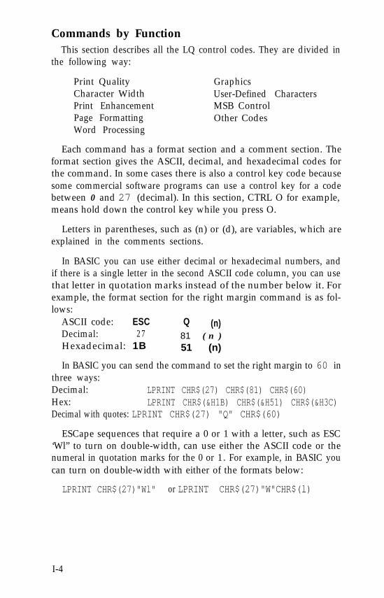
Commands by FunctionThis section describes all the LQ control codes. They are divided in
the following way:
Print QualityCharacter WidthPrint EnhancementPage FormattingWord Processing
GraphicsUser-Defined CharactersMSB ControlOther Codes
Each command has a format section and a comment section. Theformat section gives the ASCII, decimal, and hexadecimal codes forthe command. In some cases there is also a control key code becausesome commercial software programs can use a control key for a codebetween 0 and 27 (decimal). In this section, CTRL O for example,means hold down the control key while you press O.
Letters in parentheses, such as (n) or (d), are variables, which areexplained in the comments sections.
In BASIC you can use either decimal or hexadecimal numbers, andif there is a single letter in the second ASCII code column, you can usethat letter in quotation marks instead of the number below it. Forexample, the format section for the right margin command is as fol-lows:
ASCII code: ESC Q (n)Decimal: 27 81 ( n )Hexadecimal: 1B 51 (n)
In BASIC you can send the command to set the right margin to 60 inthree ways:Decimal: LPRINT CHR$(27) CHR$(81) CHR$(60)Hex: LPRINT CHR$(&H1B) CHR$(&H51) CHR$(&H3C)Decimal with quotes: LPRINT CHR$(27) "Q" CHR$(60)
ESCape sequences that require a 0 or 1 with a letter, such as ESC‘Wl” to turn on double-width, can use either the ASCII code or thenumeral in quotation marks for the 0 or 1. For example, in BASIC youcan turn on double-width with either of the formats below:
LPRINT CHR$(27)"Wl" or LPRINT CHR$(27)"W"CHR$(l)
I-4
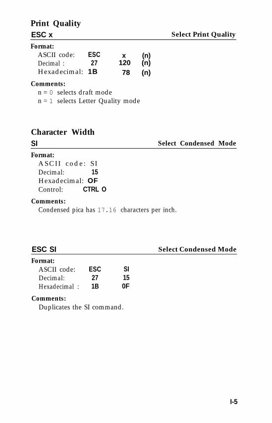
Print QualityESC x Select Print Quality
Format:ASCII code: ESCDecimal : 27Hexadecimal: 1B
x (n)120 (n)78 (n)
Comments:n = 0 selects draft moden = 1 selects Letter Quality mode
Character WidthSI Select Condensed Mode
Format:ASCII code: SIDecimal: 15Hexadecimal: OFControl: CTRL O
Comments:Condensed pica has 17.16 characters per inch.
ESC SI Select Condensed Mode
Format:ASCII code: ESC SIDecimal: 27 15Hexadecimal : 1B 0F
Comments:Duplicates the SI command.
I-5
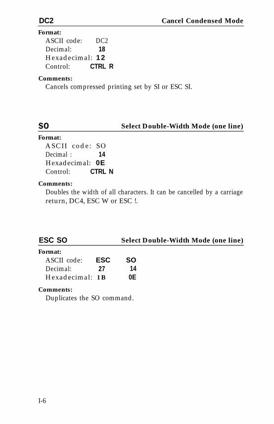
DC2 Cancel Condensed Mode
Format:ASCII code: DC2Decimal: 18Hexadecimal: 12Control: CTRL R
Comments:Cancels compressed printing set by SI or ESC SI.
soFormat:
Select Double-Width Mode (one line)
ASCII code: SODecimal : 14Hexadecimal: 0EControl: CTRL N
Comments:Doubles the width of all characters. It can be cancelled by a carriagereturn, DC4, ESC W or ESC !.
ESC SO Select Double-Width Mode (one line)
Format:ASCII code: ESC SODecimal: 27 14Hexadecimal: 1 B 0E
Comments:Duplicates the SO command.
I-6
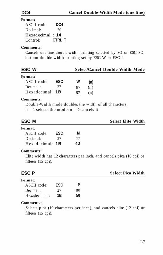
DC4 Cancel Double-Width Mode (one line)
Format:ASCII code: DC4Decimal: 20Hexadecimal : 14Control: CTRL T
Comments:Cancels one-line double-width printing selected by SO or ESC SO,but not double-width printing set by ESC W or ESC !.
ESC W Select/Cancel Double-Width Mode
Format:ASCII code: ESC W (n)Decimal : 27 87 (n)Hexadecimal: 1B 57 (n)
Comments:Double-Width mode doubles the width of all characters.n = 1 selects the mode; n = 0 cancels it
ESC M Select Elite Width
Format:ASCII code: ESC MDecimal: 27 77Hexadecimal: 1B 4D
Comments:Elite width has 12 characters per inch, and cancels pica (10 cpi) orfifteen (15 cpi).
ESC P Select Pica Width
Format:ASCII code: ESC PDecimal : 27 80Hexadecimal : 1B 50
Comments:Selects pica (10 characters per inch), and cancels elite (12 cpi) orfifteen (15 cpi).
I-7
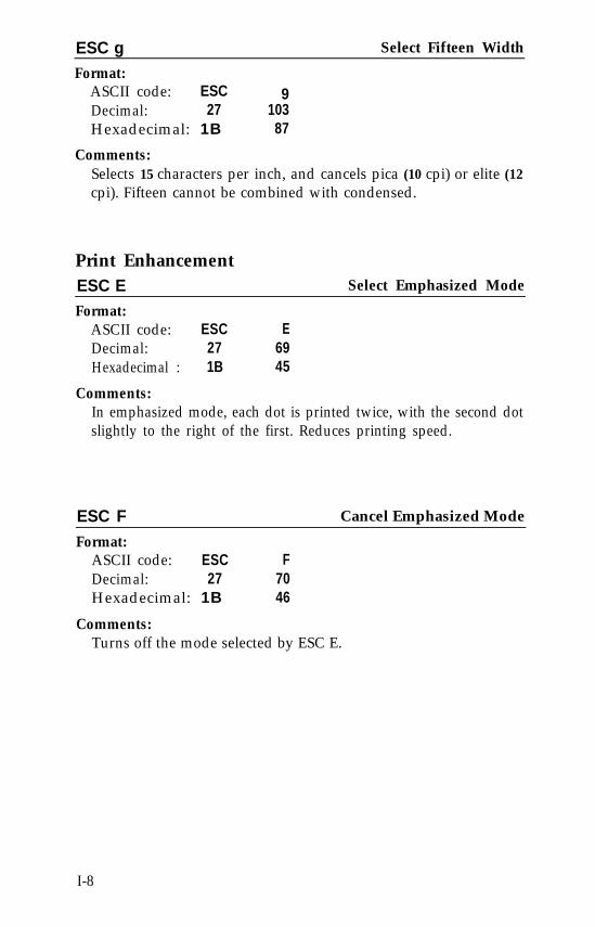
ESC g Select Fifteen Width
Format:ASCII code: ESC 9Decimal: 27 103Hexadecimal: 1B 87
Comments:Selects 15 characters per inch, and cancels pica (10 cpi) or elite (12cpi). Fifteen cannot be combined with condensed.
Print EnhancementESC EFormat:
ASCII code: ESCDecimal: 27Hexadecimal : 1B
E6945
Select Emphasized Mode
Comments:In emphasized mode, each dot is printed twice, with the second dotslightly to the right of the first. Reduces printing speed.
ESC F Cancel Emphasized Mode
Format:ASCII code: ESC FDecimal: 27 70Hexadecimal: 1B 46
Comments:Turns off the mode selected by ESC E.
I-8
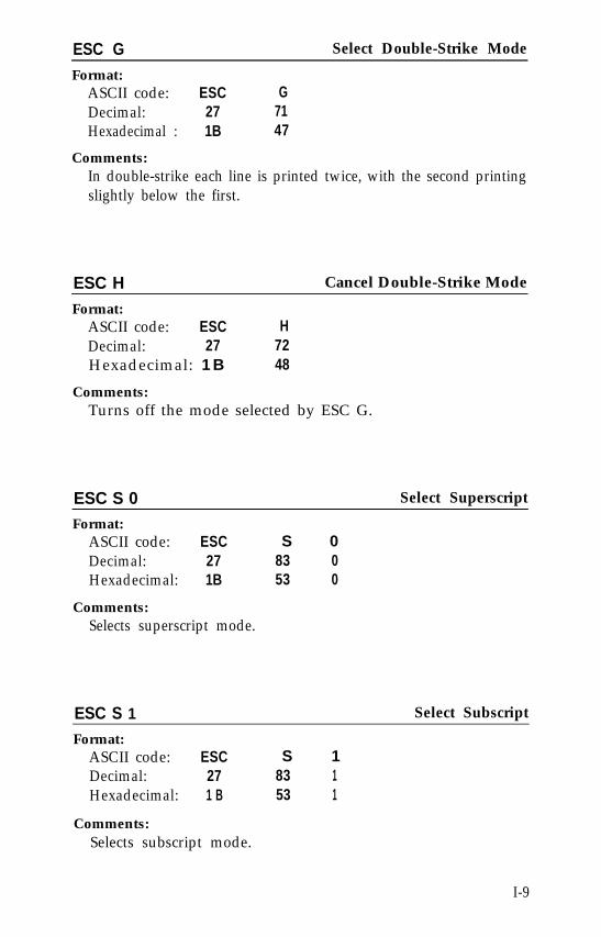
ESC G Select Double-Strike Mode
Format:ASCII code: ESC GDecimal: 27 71Hexadecimal : 1B 47
Comments:In double-strike each line is printed twice, with the second printingslightly below the first.
ESC H Cancel Double-Strike Mode
Format:ASCII code: ESC HDecimal: 27 72Hexadecimal: 1 B 48
Comments:Turns off the mode selected by ESC G.
ESC S 0 Select Superscript
Format:ASCII code: ESC S 0Decimal: 27 83 0Hexadecimal: 1B 53 0
Comments:Selects superscript mode.
ESC S 1 Select Subscript
Format:ASCII code: ESC S 1Decimal: 27 83 1Hexadecimal: 1 B 53 1
Comments:Selects subscript mode.
I-9
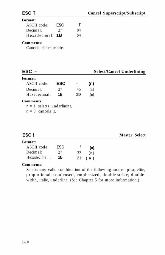
ESC TFormat:
ASCII code: ESCDecimal: 27Hexadecimal: 1B
Comments:Cancels either mode.
Cancel Superscript/Subscript
T8454
ESC - Select/Cancel Underlining
Format:ASCII code: ESC - (n)Decimal: 27 45 (n)Hexadecimal : 1B 2D (n)
Comments:n = 1 selects underliningn = 0 cancels it.
ESC ! Master Select
Format:ASCII code: ESC ! (n)Decimal: 27 33 (n)Hexadecimal : 1B 21 ( n )
Comments:Selects any valid combination of the following modes: pica, elite,proportional, condensed, emphasized, double-strike, double-width, italic, underline. (See Chapter 5 for more information.)
I-10
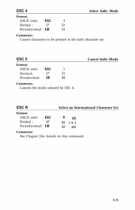
ESC 4 Select Italic Mode
Format:ASCII code: ESCDecimal : 27Hexadecimal: 1B
45234
Comments:Causes characters to be printed in the italic character set.
ESC 5 Cancel Italic Mode
Format:ASCII code: ESC 5Decimal: 27 53Hexadecimal: 1B 35
Comments:Cancels the mode selected by ESC 4.
ESC R Select an International Character Set
Format:ASCII code:Decimal :
ESC R (n)27 82 ( n )
Hexadecimal: 1B
Comments:
52 (n)
See Chapter 5 for details on this command.
I-11

Page Formatting
Margins
ESC Q Set Right Margin
Format:ASCII code: ESC Q (n)Decimal: 27 81 ( n )Hexadecimal: 1B 51 (n)
Comments:Sets the right margin. Also cancels all text in the print buffer.The range of n is 1 to 255.
ESC IFormat:
ASCII code: ESCDecimal: 27Hexadecimal: 1B
Comments:Sets the left margin.
I (n)108 (n)6C ( n )
Set Left Margin
n = first printing column in the current widthThe value of n is 0 to 255.Clears previous tab settings; therefore should be set before tabs areset. Use lowercase 1, not the numeral one.
I-12
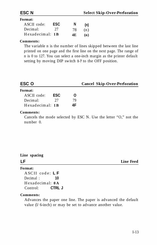
ESC NFormat:
ASCII code: ESCDecimal: 27Hexadecimal: 1 B
Comments:
Select Skip-Over-Perforation
N (n)78 (n)4E (n)
The variable n is the number of lines skipped between the last lineprinted on one page and the first line on the next page. The range ofn is 0 to 127. You can select a one-inch margin as the printer defaultsetting by moving DIP switch 1-7 to the OFF position.
ESC O Cancel Skip-Over-Perforation
Format:ASCII code: ESC ODecimal: 27 79Hexadecimal: 1 B 4F
Comments:Cancels the mode selected by ESC N. Use the letter “O,” not thenumber 0.
Line spacing
LF Line Feed
Format:ASCII code: L FDecimal : 10Hexadecimal: 0 AControl: CTRL J
Comments:Advances the paper one line. The paper is advanced the defaultvalue (l/6-inch) or may be set to advance another value.
I-13
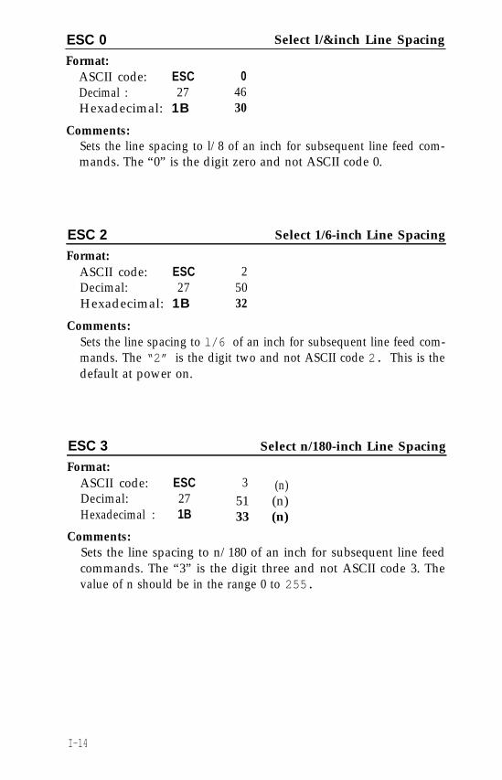
ESC 0 Select l/&inch Line Spacing
Format:ASCII code: ESC 0Decimal : 27 46Hexadecimal: 1B 30
Comments:Sets the line spacing to l/8 of an inch for subsequent line feed com-mands. The “0” is the digit zero and not ASCII code 0.
ESC 2 Select 1/6-inch Line Spacing
Format:ASCII code: ESC 2Decimal: 27 50Hexadecimal: 1B 32
Comments:Sets the line spacing to l/6 of an inch for subsequent line feed com-mands. The “2” is the digit two and not ASCII code 2. This is thedefault at power on.
ESC 3 Select n/180-inch Line Spacing
Format:ASCII code: ESC 3 (n)Decimal: 27 51 (n)Hexadecimal : 1B 33 (n)
Comments:Sets the line spacing to n/180 of an inch for subsequent line feedcommands. The “3” is the digit three and not ASCII code 3. Thevalue of n should be in the range 0 to 255.
I-14
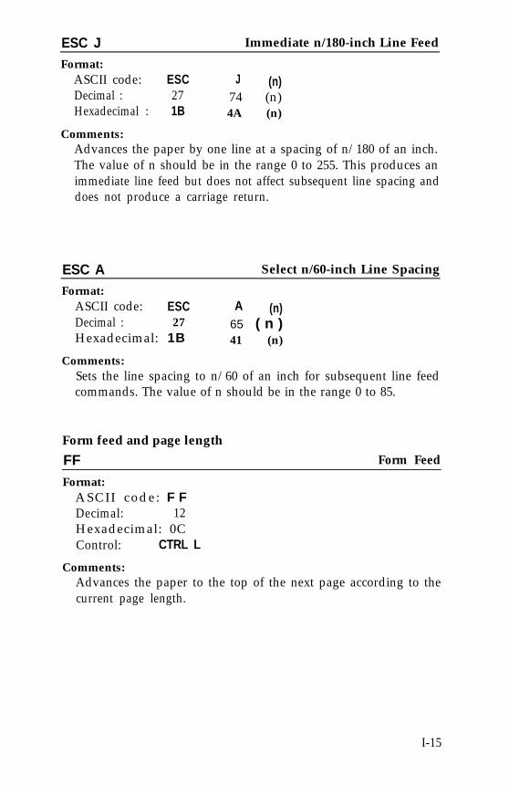
ESC J Immediate n/180-inch Line Feed
Format:ASCII code: ESC J (n)Decimal : 27 74 (n)Hexadecimal : 1B 4A (n)
Comments:Advances the paper by one line at a spacing of n/180 of an inch.The value of n should be in the range 0 to 255. This produces animmediate line feed but does not affect subsequent line spacing anddoes not produce a carriage return.
ESC A Select n/60-inch Line Spacing
Format:ASCII code: ESC A (n)Decimal : 27 65 ( n )Hexadecimal: 1B 41 (n)
Comments:Sets the line spacing to n/60 of an inch for subsequent line feedcommands. The value of n should be in the range 0 to 85.
Form feed and page length
FF Form Feed
Format:ASCII code: F FDecimal: 12Hexadecimal: 0CControl: CTRL L
Comments:Advances the paper to the top of the next page according to thecurrent page length.
I-15
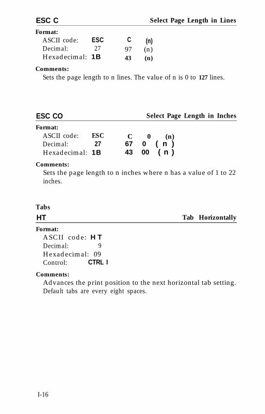
ESC C Select Page Length in Lines
Format:ASCII code: ESC C (n)Decimal: 27 97 (n)Hexadecimal: 1B 43 (n)
Comments:Sets the page length to n lines. The value of n is 0 to 127 lines.
ESC CO Select Page Length in Inches
Format:ASCII code: ESC C 0 (n)Decimal: 27 67 0 ( n )Hexadecimal: 1B 43 00 ( n )
Comments:Sets the page length to n inches where n has a value of 1 to 22inches.
Tabs
HT Tab Horizontally
Format:ASCII code: H TDecimal: 9Hexadecimal: 09Control: CTRL I
Comments:Advances the print position to the next horizontal tab setting.Default tabs are every eight spaces.
I-16
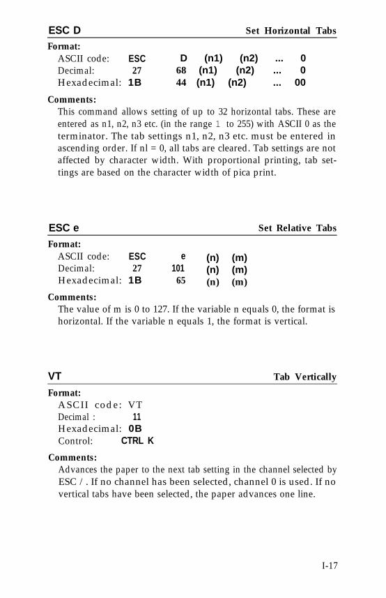
ESC DFormat:
ASCII code: ESCDecimal: 27Hexadecimal: 1B
Set Horizontal Tabs
D (n1) (n2) ... 068 (n1) (n2) ... 044 (n1) (n2) ... 00
Comments:This command allows setting of up to 32 horizontal tabs. These areentered as n1, n2, n3 etc. (in the range 1 to 255) with ASCII 0 as theterminator. The tab settings n1, n2, n3 etc. must be entered inascending order. If nl = 0, all tabs are cleared. Tab settings are notaffected by character width. With proportional printing, tab set-tings are based on the character width of pica print.
ESC e Set Relative Tabs
Format:ASCII code: ESC e (n) (m)Decimal: 27 101 (n) (m)Hexadecimal: 1B 65 (n) (m)
Comments:The value of m is 0 to 127. If the variable n equals 0, the format ishorizontal. If the variable n equals 1, the format is vertical.
VT
Format:ASCII code: VTDecimal : 11Hexadecimal: 0BControl: CTRL K
Comments:
Tab Vertically
Advances the paper to the next tab setting in the channel selected byESC /. If no channel has been selected, channel 0 is used. If novertical tabs have been selected, the paper advances one line.
I-17
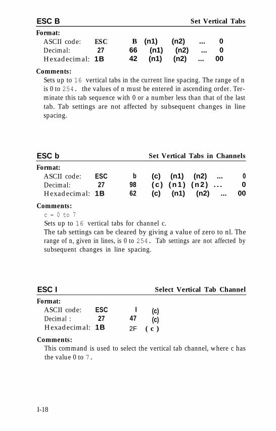
ESC B Set Vertical Tabs
Format:ASCII code: ESCDecimal: 27Hexadecimal: 1B
Comments:
B (n1) (n2) ... 066 (n1) (n2) ... 042 (n1) (n2) ... 00
Sets up to 16 vertical tabs in the current line spacing. The range of nis 0 to 254. the values of n must be entered in ascending order. Ter-minate this tab sequence with 0 or a number less than that of the lasttab. Tab settings are not affected by subsequent changes in linespacing.
ESC b Set Vertical Tabs in Channels
Format:ASCII code: ESC b (c) (n1) (n2) ... 0Decimal: 27 98 ( c ) ( n 1 ) ( n 2 ) . . . 0Hexadecimal: 1B 62 (c) (n1) (n2) ... 00
Comments:c = 0 to 7Sets up to 16 vertical tabs for channel c.The tab settings can be cleared by giving a value of zero to nl. Therange of n, given in lines, is 0 to 254. Tab settings are not affected bysubsequent changes in line spacing.
ESC I Select Vertical Tab Channel
Format:ASCII code: ESCDecimal : 27Hexadecimal: 1B
I (c)47 (c)2F ( c )
Comments:This command is used to select the vertical tab channel, where c hasthe value 0 to 7.
I-18
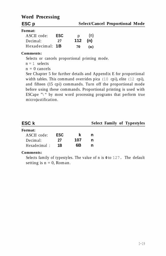
Word ProcessingESC pFormat:
ASCII code: ESCDecimal: 27Hexadecimal: 1B
Comments:
Select/Cancel Proportional Mode
p (n)112 (n)70 (n)
Selects or cancels proportional printing mode.n = 1 selectsn = 0 cancelsSee Chapter 5 for further details and Appendix E for proportionalwidth tables. This command overrides pica (10 cpi), elite (12 cpi),and fifteen (15 cpi) commands. Turn off the proportional modebefore using these commands. Proportional printing is used withESCape ”\“ by most word processing programs that perform truemicrojustification.
ESC k Select Family of Typestyles
Format:ASCII code: ESC k nDecimal: 27 107 nHexadecimal : 1B 6B n
Comments:Selects family of typestyles. The value of n is 0 to 127. The defaultsetting is n = 0, Roman.
I-19
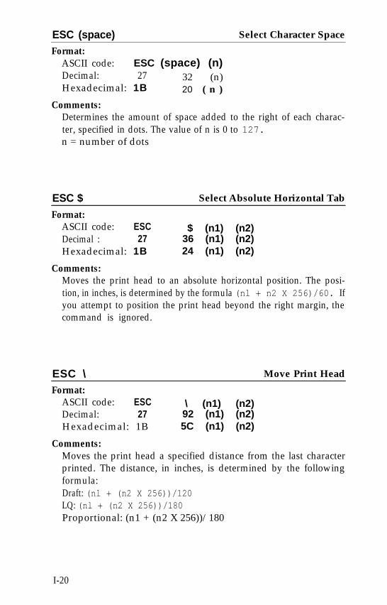
ESC (space) Select Character Space
Format:ASCII code: ESC (space) (n)Decimal: 27 32 (n)Hexadecimal: 1B 20 ( n )
Comments:Determines the amount of space added to the right of each charac-ter, specified in dots. The value of n is 0 to 127.n = number of dots
ESC $ Select Absolute Horizontal Tab
Format:ASCII code: ESCDecimal : 27Hexadecimal: 1B
Comments:
$ (n1) (n2)36 (n1) (n2)24 (n1) (n2)
Moves the print head to an absolute horizontal position. The posi-tion, in inches, is determined by the formula (nl + n2 X 256)/60. Ifyou attempt to position the print head beyond the right margin, thecommand is ignored.
ESC \ Move Print Head
Format:ASCII code: ESCDecimal: 27Hexadecimal: 1B
Comments:
\ (n1) (n2)92 (n1) (n2)5C (n1) (n2)
Moves the print head a specified distance from the last characterprinted. The distance, in inches, is determined by the followingformula:Draft: (nl + (n2 X 256))/120LQ: (nl + (n2 X 256))/180Proportional: (n1 + (n2 X 256))/180
I-20
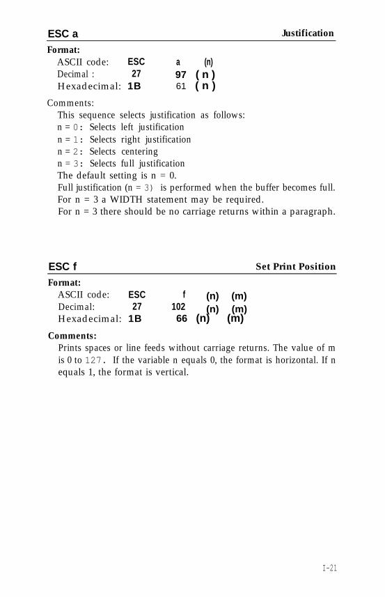
ESC aFormat:
ASCII code: ESCDecimal : 27Hexadecimal: 1B
a (n)97 ( n )61 ( n )
Justification
Comments:This sequence selects justification as follows:n = 0: Selects left justificationn = 1: Selects right justificationn = 2: Selects centeringn = 3: Selects full justificationThe default setting is n = 0.Full justification (n = 3) is performed when the buffer becomes full.For n = 3 a WIDTH statement may be required.For n = 3 there should be no carriage returns within a paragraph.
ESC f Set Print Position
Format:ASCII code: ESC f (n) (m)Decimal: 27 102Hexadecimal: 1B
(n) (m)66 (n) (m)
Comments:Prints spaces or line feeds without carriage returns. The value of mis 0 to 127. If the variable n equals 0, the format is horizontal. If nequals 1, the format is vertical.
I-21
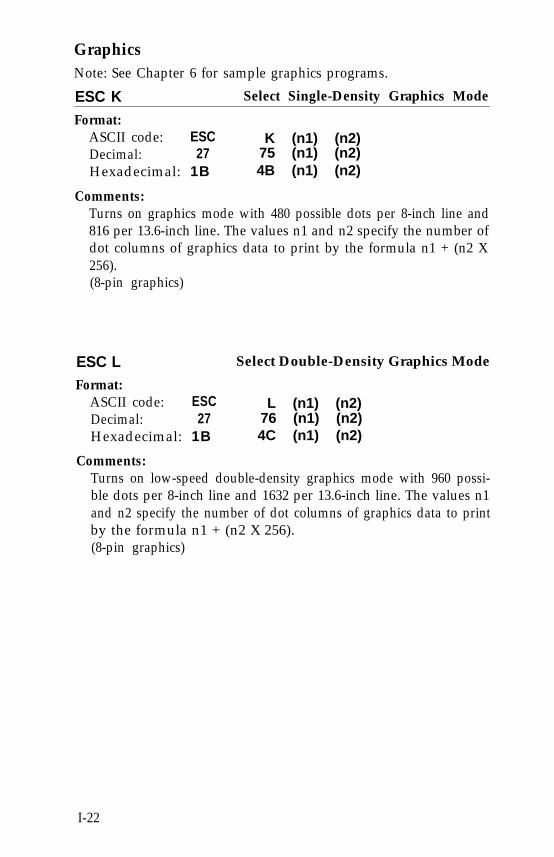
GraphicsNote: See Chapter 6 for sample graphics programs.
ESC K Select Single-Density Graphics Mode
Format:ASCII code: ESC K (n1) (n2)Decimal: 27 75 (n1) (n2)Hexadecimal: 1B 4B (n1) (n2)
Comments:Turns on graphics mode with 480 possible dots per 8-inch line and816 per 13.6-inch line. The values n1 and n2 specify the number ofdot columns of graphics data to print by the formula n1 + (n2 X256).(8-pin graphics)
ESC L Select Double-Density Graphics Mode
Format:ASCII code: ESCDecimal: 27Hexadecimal: 1B
Comments:
L (n1) (n2)76 (n1) (n2)4C (n1) (n2)
Turns on low-speed double-density graphics mode with 960 possi-ble dots per 8-inch line and 1632 per 13.6-inch line. The values n1and n2 specify the number of dot columns of graphics data to printby the formula n1 + (n2 X 256).(8-pin graphics)
I-22
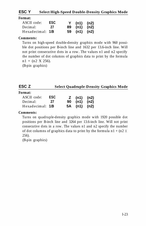
ESC Y Select High-Speed Double-Density Graphics Mode
Format:ASCII code: ESCDecimal: 27Hexadecimal: 1B
Comments:
Y (n1) (n2)89 (n1) (n2)59 (n1) (n2)
Turns on high-speed double-density graphics mode with 960 possi-ble dot positions per B-inch line and 1632 per 13.6-inch line. Willnot print consecutive dots in a row. The values n1 and n2 specifythe number of dot columns of graphics data to print by the formulan1 + (n2 X 256).(B-pin graphics)
ESC Z Select Quadruple-Density Graphics Mode
Format:ASCII code: ESC Z (n1) (n2)Decimal: 27 90 (n1) (n2)Hexadecimal: 1B 5A (n1) (n2)
Comments:Turns on quadruple-density graphics mode with 1920 possible dotpositions per B-inch line and 3264 per 13.6-inch line. Will not printconsecutive dots in a row. The values n1 and n2 specify the numberof dot columns of graphics data to print by the formula n1 + (n2 X256).(B-pin graphics)
I-23
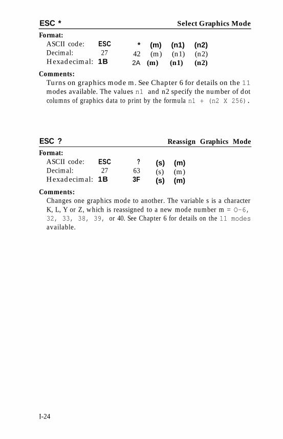
ESC * Select Graphics Mode
Format:ASCII code: ESCDecimal: 27Hexadecimal: 1B
* (m) (n1) (n2)42 (m) (n1) (n2)2A (m) (n1) (n2)
Comments:Turns on graphics mode m. See Chapter 6 for details on the 11modes available. The values n1 and n2 specify the number of dotcolumns of graphics data to print by the formula n1 + (n2 X 256).
ESC ? Reassign Graphics Mode
Format:ASCII code: ESC ? (s) (m)Decimal: 27 63 (s) (m)Hexadecimal: 1B 3F (s) (m)
Comments:Changes one graphics mode to another. The variable s is a characterK, L, Y or Z, which is reassigned to a new mode number m = O-6,32, 33, 38, 39, or 40. See Chapter 6 for details on the 11 modesavailable.
I-24
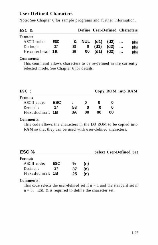
User-Defined CharactersNote: See Chapter 6 for sample programs and further information.
ESC & Define User-Defined Characters
Format:ASCII code: ESCDecimal: 27Hexadecimal: 1B
Comments:
& NUL (d1) (d2) ... (dn)38 0 (d1) (d2) ... (dn)26 00 (d1) (d2) ... (dn)
This command allows characters to be re-defined in the currentlyselected mode. See Chapter 6 for details.
ESC : Copy ROM into RAM
Format:ASCII code: ESC : 0 0 0Decimal : 27 58 0 0 0Hexadecimal: 1B 3A 00 00 00
Comments:This code allows the characters in the LQ ROM to be copied intoRAM so that they can be used with user-defined characters.
ESC % Select User-Defined Set
Format:ASCII code: ESC % (n)Decimal : 27 37 (n)Hexadecimal: 1B 25 (n)
Comments:This code selects the user-defined set if n = 1 and the standard set ifn = 0. ESC & is required to define the character set.
I-25
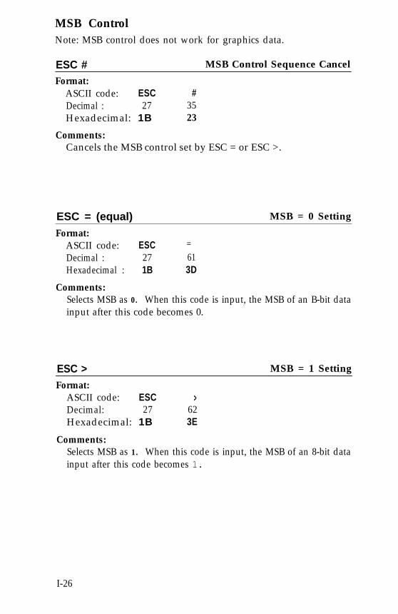
MSB ControlNote: MSB control does not work for graphics data.
ESC # MSB Control Sequence Cancel
Format:ASCII code: ESC #Decimal : 27 35Hexadecimal: 1B 23
Comments:Cancels the MSB control set by ESC = or ESC >.
ESC = (equal) MSB = 0 Setting
Format:ASCII code: ESC =
Decimal : 27 61Hexadecimal : 1B 3D
Comments:Selects MSB as 0. When this code is input, the MSB of an B-bit datainput after this code becomes 0.
ESC > MSB = 1 Setting
Format:ASCII code: ESC >Decimal: 27 62Hexadecimal: 1B 3E
Comments:Selects MSB as 1. When this code is input, the MSB of an 8-bit datainput after this code becomes 1.
I-26
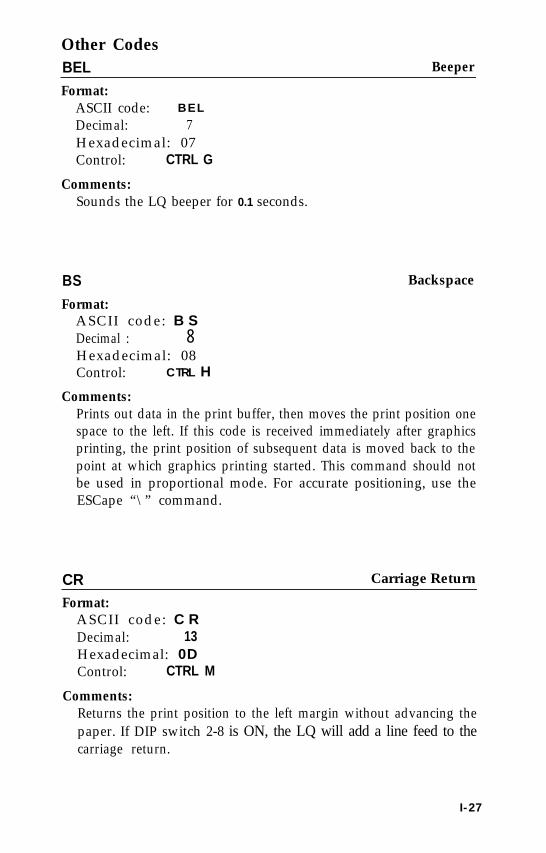
Other CodesBEL Beeper
Format:ASCII code: B E L
Decimal: 7Hexadecimal: 07Control: CTRL G
Comments:Sounds the LQ beeper for 0.1 seconds.
BS Backspace
Format:ASCII code: B SDecimal : 8Hexadecimal: 08Control: CTRL H
Comments:Prints out data in the print buffer, then moves the print position onespace to the left. If this code is received immediately after graphicsprinting, the print position of subsequent data is moved back to thepoint at which graphics printing started. This command should notbe used in proportional mode. For accurate positioning, use theESCape “\” command.
CR Carriage Return
Format:ASCII code: C RDecimal: 13Hexadecimal: 0DControl: CTRL M
Comments:Returns the print position to the left margin without advancing thepaper. If DIP switch 2-8 is ON, the LQ will add a line feed to thecarriage return.
I-27
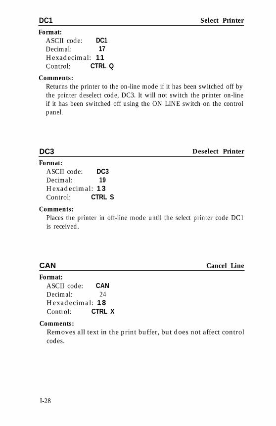
DC1 Select Printer
Format:ASCII code: DC1Decimal: 17Hexadecimal: 11Control: CTRL Q
Comments:Returns the printer to the on-line mode if it has been switched off bythe printer deselect code, DC3. It will not switch the printer on-lineif it has been switched off using the ON LINE switch on the controlpanel.
DC3 Deselect Printer
Format:ASCII code: DC3Decimal: 19Hexadecimal: 13Control: CTRL S
Comments:Places the printer in off-line mode until the select printer code DC1is received.
CAN Cancel Line
Format:ASCII code: CANDecimal: 24Hexadecimal: 18Control: CTRL X
Comments:Removes all text in the print buffer, but does not affect controlcodes.
I-28
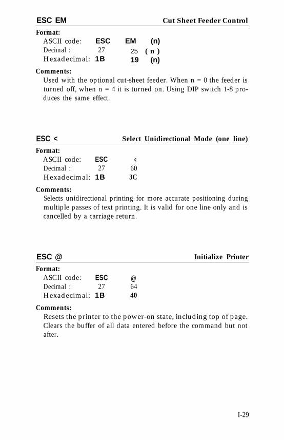
ESC EM Cut Sheet Feeder Control
Format:ASCII code: ESC EM (n)Decimal : 27 25 ( n )Hexadecimal: 1B 19 (n)
Comments:Used with the optional cut-sheet feeder. When n = 0 the feeder isturned off, when n = 4 it is turned on. Using DIP switch 1-8 pro-duces the same effect.
ESC < Select Unidirectional Mode (one line)
Format:ASCII code: ESCDecimal : 27Hexadecimal: 1B
Comments:
<603C
Selects unidirectional printing for more accurate positioning duringmultiple passes of text printing. It is valid for one line only and iscancelled by a carriage return.
ESC @ Initialize Printer
Format:ASCII code: ESC @Decimal : 27 64Hexadecimal: 1B 40
Comments:Resets the printer to the power-on state, including top of page.Clears the buffer of all data entered before the command but notafter.
I-29
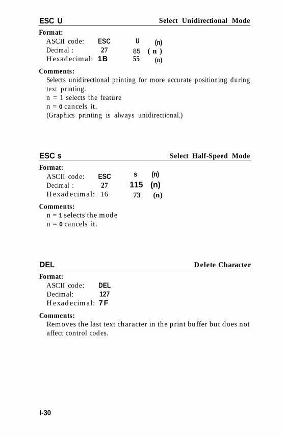
ESC U Select Unidirectional Mode
Format:ASCII code: ESCDecimal : 27Hexadecimal: 1B
Comments:
U (n)85 ( n )55 (n)
Selects unidirectional printing for more accurate positioning duringtext printing.n = 1 selects the featuren = 0 cancels it.(Graphics printing is always unidirectional.)
ESC s Select Half-Speed Mode
Format:ASCII code: ESCDecimal : 27 115 (n)
s (n)
Hexadecimal: 16 73 (n)
Comments:n = 1 selects the moden = 0 cancels it.
DEL Delete Character
Format:ASCII code: DELDecimal: 127Hexadecimal: 7F
Comments:Removes the last text character in the print buffer but does notaffect control codes.
I-30
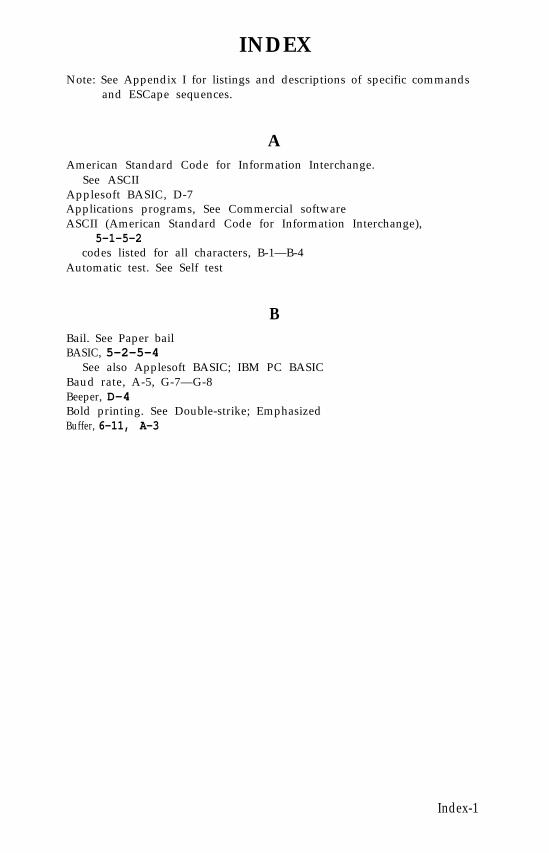
INDEXNote: See Appendix I for listings and descriptions of specific commands
and ESCape sequences.
AAmerican Standard Code for Information Interchange.
See ASCIIApplesoft BASIC, D-7Applications programs, See Commercial softwareASCII (American Standard Code for Information Interchange),
5-1—5-2codes listed for all characters, B-1—B-4
Automatic test. See Self test
BBail. See Paper bailBASIC, 5-2-5-4
See also Applesoft BASIC; IBM PC BASICBaud rate, A-5, G-7—G-8Beeper, D-4Bold printing. See Double-strike; EmphasizedBuffer, 6-11, A-3
Index-1
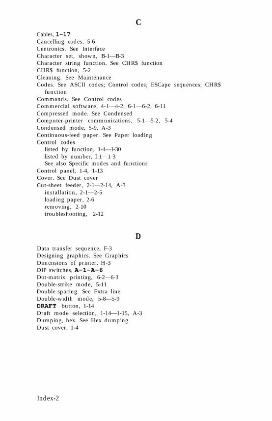
CCables, 1-17Cancelling codes, 5-6Centronics. See InterfaceCharacter set, shown, B-1—B-3Character string function. See CHR$ functionCHR$ function, 5-2Cleaning. See MaintenanceCodes. See ASCII codes; Control codes; ESCape sequences; CHR$
functionCommands. See Control codesCommercial software, 4-1—4-2, 6-1—6-2, 6-11Compressed mode. See CondensedComputer-printer communications, 5-1—5-2, 5-4Condensed mode, 5-9, A-3Continuous-feed paper. See Paper loadingControl codes
listed by function, 1-4—I-30listed by number, I-1—1-3See also Specific modes and functions
Control panel, 1-4, 1-13Cover. See Dust coverCut-sheet feeder, 2-1—2-14, A-3
installation, 2-1—2-5loading paper, 2-6removing, 2-10troubleshooting, 2-12
DData transfer sequence, F-3Designing graphics. See GraphicsDimensions of printer, H-3DIP switches, A-1-A-6Dot-matrix printing, 6-2—6-3Double-strike mode, 5-11Double-spacing. See Extra lineDouble-width mode, 5-8—5-9DRAFT button, 1-14Draft mode selection, 1-14—1-15, A-3Dumping, hex. See Hex dumpingDust cover, 1-4
Index-2
EElite mode, 5-5Emphasized mode, 5-10Environment, specifications for, H-3Epson computers. See QX-10 and QX-16Error warnings, D-4ESCape sequences, 5-1—5-2
listed by function, I-4—I-30listed by number, I-1—1-3
Expanded mode. See Double-widthExtra line, D-3
FFifteen mode, 5-5Firing of pins. See PinsFORM FEED button, 1-14Foreign language characters. See International charactersFormatting, page, 5-18—5-21Friction-control lever. See Paper release leverFriction feed. See Paper loading, single-sheetFunction switches. See DIP switches
GGraphics, 6-1—6-11
designing, 6-5—6-10dot patterns, 6-38-pin, 6-324-pin, 6-3options, 6-5, 6-10pin labels, 6-3—6-5reassigning code, 6-10
HHalf-speed, 5-21Head. See Print headHex dumping, D-4—D-6Horizontal tabs. See Tabs
Index-3
IIBM PC BASIC, D-6Initialization, 5-7Interface. See Parallel interface; Serial interfaceInternational characters, 5-15—5-17Italic mode, I-11
Knob. See Paper-feed knob
K
LLabels, self-adhesive, B4-B5, D2Left margin, 5-18Letter Quality
button, 1-14mode selection, 1-14-1-15, 5-6, 5-8
Lever. See Paper release; Paper thickness; Pin feedLINE FEED button, 1-14Lid. See Dust coverLine feed, DIP switch for, A-4Line spacing, 5-17Location of printer, 1-3LQ. See Letter QualityLubrication, D-8-D-9
MMaintenance, D-8
cut sheet feeder, 2-13—2-14Manual feed knob. See Paper feed knobMargins, 5-18Master Select, 5-13
OOFF LINE button, 1-13—1-14ON LINE light and button, 1-13—1-14Option cartridge
DIP switch setting, A-4Overprinting, D-2
Index-4
PPage
top of. See Top-of-pageformatting, 5-18—5-21
Panel buttons, 1-13—1-14Paper
bail, 1-9, 2-1, 3-3feed knob, 1-2release lever, 1-4, 1-9separator, 3-8—3-9thickness lever, 1-11
Paper loadingcontinuous-feed, 3-1, 3-3—3-8single-sheet, 1-8—1-11troubleshooting, D-1
Parallel interface, 1-17, F-1-F-4Parts, printer, 1-1Pica mode, 5-5Pin-feed paper. See Paper loading, continuous-feedPin-feed holder and pin-feed lever, 3-14Pins, firing and numbering, 6-3—6-4Pitches. See Widths
See also widths by namePower switch, 1-12Print head replacement, D-8—D-9Print width summary table, 5-20
See also specific widths by namePrint width, 5-5—5-6Proportional mode, 5-12, E-1—E-4Protective lid. See Dust cover
QQX-10 and QX-16, D-8
RREADY light, 1-12Reset code, 5-6—5-7Resetting. See Reset codeRibbon installation and replacement, 1-5—1-8Right margin, 5-18
Index-5
SSelf test, 1-15Sensor. See Paper out sensorSeparator. See Paper separatorSerial Interface, 1-17, F-5, H-4
DIP switch settings, A-2, A-4—A-5Setup
commercial software, 4-1-4-2printer, 1-1—1-11
Single-sheet printing, 1-8-1-11Skip-over-perforation, 5-19, A-3Spacing. See Line spacingSpecifications. See Technical specificationsSubscript, 5-15Superscript, 5-15Switches. See DIP switches
TTabs, 1-16, 1-17Technical specifications, H-1—H-4Temperature, H-3Test. See Self testTop-of-form. See Top-of-pageTop-of-page, 2-8, 3-8Tractor, 3-1—3-11
installation, 3-2removing, 3-11
Troubleshooting, D-1—D-7cut sheet feeder, 2-12
UUnderline mode, 5-12Unpacking your printer, 1-1User-defined characters, 6-11—6-20
defining, 6-13design grids, 6-11printing, 6-16—6-20
Index-6
Vertical tabs. See Tabs
V
WWord processing, 4-1—4-2
Index-7
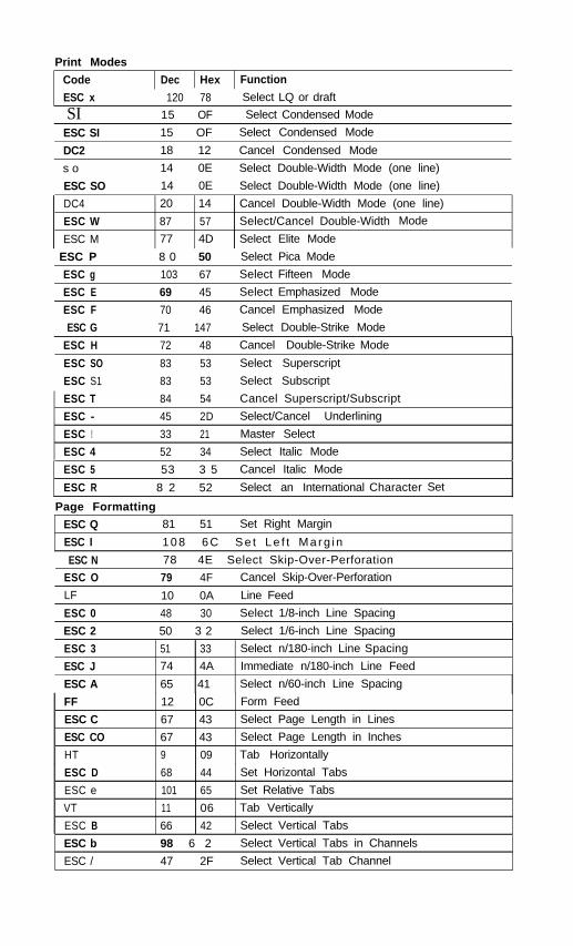
Print Modes
Code
ESC x
Dec Hex Function
120 78 Select LQ or draft
SI 15 OF Select Condensed Mode
ESC SI
DC2
s o
ESC SO
15 OF Select Condensed Mode
18 12 Cancel Condensed Mode
14 0E Select Double-Width Mode (one line)
14 0E Select Double-Width Mode (one line)
DC4
ESC W
ESC M
20 14 Cancel Double-Width Mode (one line)
87 57 Select/Cancel Double-Width Mode
77 4D Select Elite Mode
ESC P 8 0 50 Select Pica Mode
ESC g 103 67 Select Fifteen Mode
ESC E 69 45 Select Emphasized Mode
ESC F 70 46 Cancel Emphasized Mode
ESC G 71 147 Select Double-Strike Mode
ESC H 72 48 Cancel Double-Strike Mode
ESC SO 83 53 Select Superscript
ESC S1 83 53 Select Subscript
ESC T 84 54 Cancel Superscript/Subscript
ESC - 45 2D Select/Cancel Underlining
ESC ! 33 21 Master Select
ESC 4 52 34 Select Italic Mode
ESC 5 53 3 5 Cancel Italic Mode
ESC R 8 2 52 Select an International Character Set
Page Formatting
ESC Q 81 51 Set Right Margin
ESC I 1 0 8 6 C S e t L e f t M a r g i n
ESC NESC O
LF
ESC 0
78 4E Select Skip-Over-Perforation
79 4F Cancel Skip-Over-Perforation
10 0A Line Feed
48 30 Select 1/8-inch Line Spacing
ESC 2
ESC 3
ESC J
ESC A
50 3 2 Select 1/6-inch Line Spacing
51 33 Select n/180-inch Line Spacing
74 4A Immediate n/180-inch Line Feed
65 41 Select n/60-inch Line Spacing
FF
ESC C
ESC CO
HT
12 0C Form Feed
67 43 Select Page Length in Lines
67 43 Select Page Length in Inches
9 09 Tab Horizontally
ESC D 68 44 Set Horizontal Tabs
ESC e 101 65 Set Relative Tabs
VT 11 06 Tab Vertically
ESC B 66 42 Select Vertical Tabs
ESC b
ESC /
98 6 2 Select Vertical Tabs in Channels
47 2F Select Vertical Tab Channel
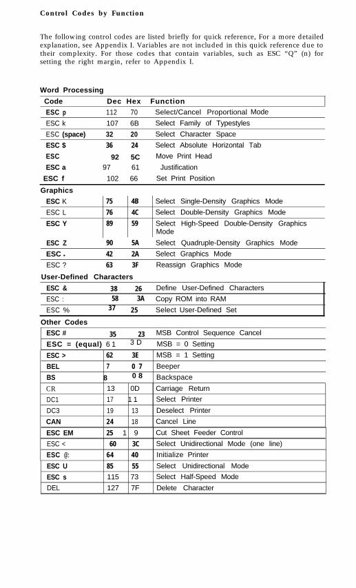
Control Codes by Function
The following control codes are listed briefly for quick reference, For a more detailedexplanation, see Appendix I. Variables are not included in this quick reference due totheir complexity. For those codes that contain variables, such as ESC “Q” (n) forsetting the right margin, refer to Appendix I.
Word Processing
Code Dec Hex Function
ESC p 112 70 Select/Cancel Proportional Mode
ESC k 107 6B Select Family of Typestyles
ESC (space) 32 20 Select Character Space
ESC $ 36 24 Select Absolute Horizontal Tab
ESC
ESC a92 5C Move Print Head
97 61 Justification
ESC f 102 66 Set Print Position
Graphics
ESC K
ESC L
ESC Y
75 4B Select Single-Density Graphics Mode
76 4C Select Double-Density Graphics Mode
89 59 Select High-Speed Double-Density GraphicsMode
ESC Z 90 5A Select Quadruple-Density Graphics Mode
ESC l 42 2A Select Graphics Mode
ESC ? 63 3F Reassign Graphics Mode
User-Defined Characters
ESC &
ESC :
ESC %
38 26 Define User-Defined Characters
58 3A Copy ROM into RAM37 25 Select User-Defined Set
Other CodesESC # 35 23 MSB Control Sequence Cancel
ESC = (equal) 6 1 3 D MSB = 0 Setting
ESC >
BEL
BS
CRDC1
DC3
CAN
62 3E MSB = 1 Setting
7 0 7 Beeper
8 0 8 Backspace
13 0D Carriage Return
17 1 1 Select Printer
19 13 Deselect Printer
24 18 Cancel Line
ESC EM
ESC <
ESC @:
25 1 9 Cut Sheet Feeder Control
60 3C Select Unidirectional Mode (one line)
64 40 Initialize Printer
ESC U
ESC sDEL
85 55 Select Unidirectional Mode
115 73 Select Half-Speed Mode
127 7F Delete Character
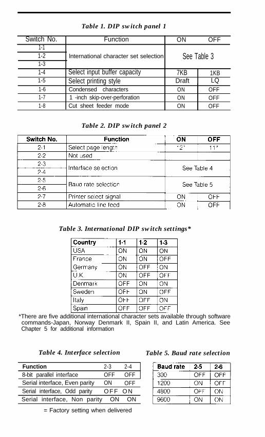
Table 1. DIP switch panel 1
Switch No. Function1-11-2 lnternational character set selection1-31-4 Select input buffer capacity1-5 Select printing style1-61-71-8
Condensed characters1 -inch skip-over-perforationCut sheet feeder mode
ON OFF
See Table 3
7KB 1KBDraft LQON OFFON OFFON OFF
Table 2. DIP switch panel 2
Table 3. International DIP switch settings*
*There are five additional international character sets available through softwarecommands-Japan, Norway Denmark II, Spain II, and Latin America. SeeChapter 5 for additional information
Table 4. Interface selection Table 5. Baud rate selection
Function 2-3 2-48-bit parallel interface OFF OFFSerial interface, Even parity ON OFFSerial interface, Odd parity O F F O N
Serial interface, Non parity ON ON
= Factory setting when delivered
EPSON AMERICA, INC.LIMITED WARRANTY
What Is Covered: Epson America, Inc. warrants that the Epson product enclosedwith this Limited Warranty conforms to the manufacturer’s specifications and is freefrom defects in workmanship and material for a period of one year from the date oforiginal purchase made in the United States.
What We Will Do To Correct Problems: Should your Epson product prove defec-tive during this period, you must promptly notify your Epson Dealer or an authorizedEpson Service Center and bring the product securely packaged in its original containeror an equivalent, along with proof of the date of original purchase, to your EpsonDealer or to an authorized Epson Service Center. Epson America, Inc. will, at itsoption, repair or replace on an exchange basis the defective unit, without charge forparts or labor. Postage, insurance or shipping costs incurred in presenting your Epsonproduct for warranty service are your responsibility.
What This Warranty Does Not Couer: This warranty covers only normal con-sumer use. Epson is not responsible for warranty service should the Epson label orlogo or the rating label or serial number be removed or should the product fail to beproperly maintained or fail to function properly as a result of misuse, abuse, improperinstallation, neglect, improper shipping, damage caused by disasters such as fire,flood, and lightning, or service other than by an authorized Epson Service Center.
THE WARRANTY AND REMEDY PROVIDED ABOVE ARE EXCLUSIVE ANDIN LIEU OF ALL OTHER EXPRESS WARRANTIES AND UNLESS STATEDHEREIN, ANY STATEMENTS OR REPRESENTATIONS MADE BY ANY OTHERPERSON OR FIRM ARE VOID. THE DURATION OF ANY IMPLIED WARRAN-TIES OF MERCHANTABILITY OR FITNESS FOR A PARTICULAR PURPOSE ONYOUR EPSON PRODUCT SHALL BE LIMITED TO THE DURATION OF THE EX-PRESS WARRANTY SET FORTH ABOVE. EXCEPT AS PROVIDED IN THISWRITTEN WARRANTY, NEITHER EPSON AMERICA, INC. NOR ITS AFFILI-ATES SHALL BE LIABLE FOR ANY LOSS, INCONVENIENCE, OR DAMAGE,INCLUDING DIRECT, SPECIAL, INCIDENTAL, OR CONSEQUENTIAL DAM-AGES, RESULTING FROM THE USE OR INABILITY TO USE THE EPSON PROD-UCT, WHETHER RESULTING FROM BREACH OF WARRANTY OR ANYOTHER LEGAL THEORY.
Some states do not allow limitations on how long an implied warranty lasts andsome states do not allow the exclusion or limitation of incidental or consequentialdamages, so the above limitation and exclusion may not apply to you.
This warranty gives you specific legal rights, and you may also have other rightswhich vary from state to state.
How To Obtain Warranty Service Information: You may request additional war-ranty service information by contacting your Epson Dealer or by contacting EpsonAmerica, Inc. at the address or phone number printed below:
Epson America, Inc.Service Division23610 Telo StreetTorrance, CA 90505(213)534-4234
• • •
G-01