Embed Size (px)
Citation preview
* Corresponding author: [email protected]
FCB system analysis and performance test results of 1000MW ultra supercritical coal fired power station
Zhang Shuying1, Li Lin1, Zhang Cuihua1, Gao Yan2,* and Luan Tao3
1Shandong Electric Power Engineering Consulting Institute Co.,Ltd., Jinan, Shandong, 250013, China 2Department of Thermal Engineering, Shandong Jianzhu University, Jinan 250101, China 3School of energy and power engineering, Shandong University, Jinan 250101, China
Abstract. Fast cut back (FCB) function can make the power station restore the external power supply in a very short period of time from the auxiliary power operation conditions through self-help mode. In case of large-scale power grid failure, FCB further ensures the safety of the main equipments and bring great benefits for the rapid recovery of local power grid. Taking Taishan Power Plant 1000 MW unit as a research object, the feasibility scheme of adding FCB function was analyzed and demonstrated on the basis of making full use of the original equipment design margin. The FCB test of TMCR 100% load was completed. The test results and problems during FCB process were discussed, and the corresponding countermeasures were proposed.
1 Introduction
Fast Cut Back (FCB) refers to the automatic control function that the generator set with load more than 35% is disconnected from the power grid due to line fault or grid fault, and all external power supply is removed instantaneously[1]. Under this condition, the boiler does not extinguish fire, the automatic control function of fast reducing output is realized to maintain its own auxiliary power operation or shutdown without boiler shutdown[2].
In order to deal with the large-scale blackout, how to recover quickly is regarded as an important research topic, in which FCB has become the focus of attention[3]. In the process of FCB, the generator outlet is cut off, while the steam turbine and boiler are in normal operation, or the boiler is in normal operation with the steam turbine shutting down[4]. Then, the bypass of the operating generator set is opened quickly, and the load of the boiler is reduced rapidly, so as to realize the rapid reduction of output and maintain the auxiliary power operation, commonly known as island operation[5]. For large-scale power plant such as 1000 MW units, if they have FCB function, they can completely or partially restore the auxiliary power operation of generating units through self-help mode in case of large-scale power grid failure, which further ensure the safety of the main equipments of the generating set. At the same time, it can also restore the external power supply in a very short period of time, which will bring great benefits for the rapid recovery of local power grid.
In Guohua Taishan Power Plant 1000 MW unit, the FCB function was not considered in the original design. So the realization of FCB function could only be achieved by modifying some equipment on the basis of
original equipment design margin. First, the equipment status and system configuration of the unit were analyzed and evaluated, so as to confirm that the unit had the preliminary conditions for the implementation of FCB. Through the performance verification test of each subsystem and auxiliary machine, it verified the unit could carry out the FCB function transformation. Taking the opportunity of unit overhaul, some hardware modifications and relevant thermal control logic prioritization were carried out, including condensate system verification test, bypass function verification test, deaerator system verification test, feed water pump steam turbine function verification test, variable loads test, and other subsystem verification test items. Load rejection test was completed in a planned way to verify the thermal system and automatic control system of the unit. The capability met the requirements of FCB function test.
Taking the 1000 MW unit of Taishan Power Plant as the research object, the feasibility scheme of adding FCB function was analyzed and demonstrated on the basis of making full use of the original equipment design margin. The FCB test of TMCR 100% load was completed. It was verified that the main and auxiliary equipments performance and system design of the unit met the requirements of FCB function. The test results and problems during FCB process were analyzed, and the corresponding countermeasures were proposed.
2 Key equipments and thermal system
2.1 Steam turbine
E3S Web of Conferences 233, 04013 (2021)IAECST 2020
https://doi.org/10.1051/e3sconf/202123304013
© The Authors, published by EDP Sciences. This is an open access article distributed under the terms of the Creative Commons Attribution License 4.0 (http://creativecommons.org/licenses/by/4.0/).
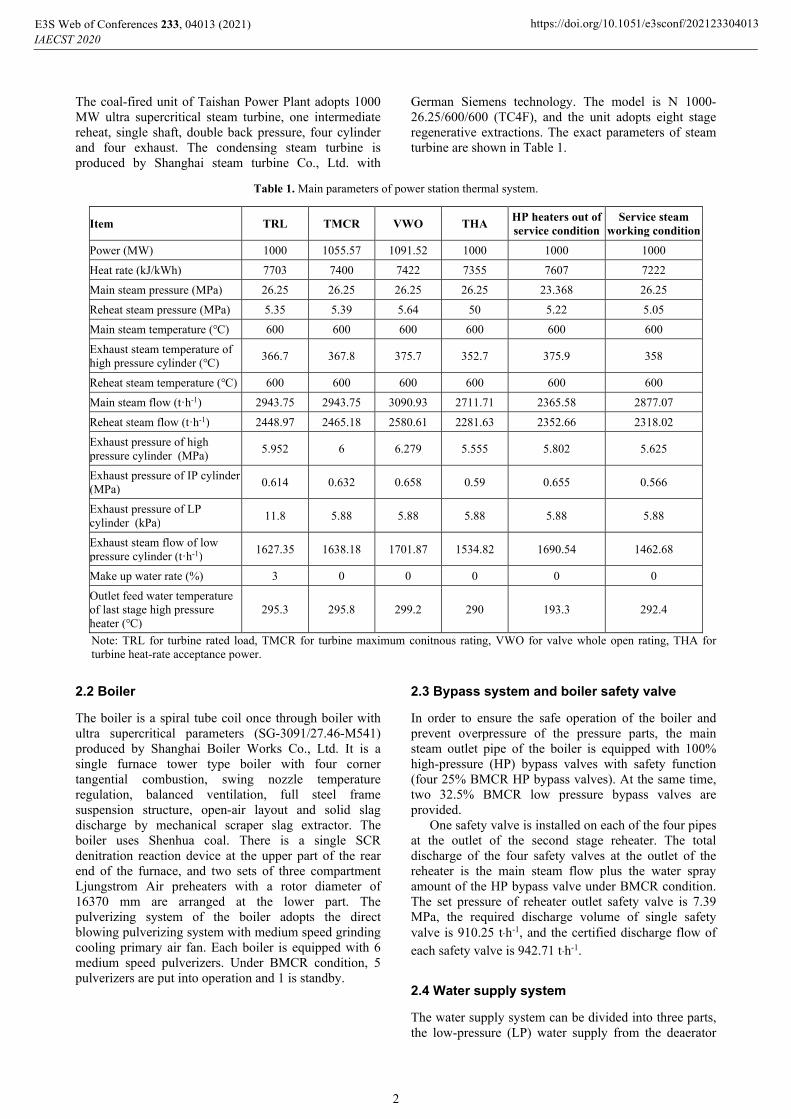
The coal-fired unit of Taishan Power Plant adopts 1000 MW ultra supercritical steam turbine, one intermediate reheat, single shaft, double back pressure, four cylinder and four exhaust. The condensing steam turbine is produced by Shanghai steam turbine Co., Ltd. with
German Siemens technology. The model is N 1000-26.25/600/600 (TC4F), and the unit adopts eight stage regenerative extractions. The exact parameters of steam turbine are shown in Table 1.
Table 1. Main parameters of power station thermal system.
Item TRL TMCR VWO THA HP heaters out of service condition
Service steam working condition
Power (MW) 1000 1055.57 1091.52 1000 1000 1000
Heat rate (kJ/kWh) 7703 7400 7422 7355 7607 7222
Main steam pressure (MPa) 26.25 26.25 26.25 26.25 23.368 26.25
Reheat steam pressure (MPa) 5.35 5.39 5.64 50 5.22 5.05
Main steam temperature (℃) 600 600 600 600 600 600
Exhaust steam temperature of high pressure cylinder (℃)
366.7 367.8 375.7 352.7 375.9 358
Reheat steam temperature (℃) 600 600 600 600 600 600
Main steam flow (tꞏh-1) 2943.75 2943.75 3090.93 2711.71 2365.58 2877.07
Reheat steam flow (tꞏh-1) 2448.97 2465.18 2580.61 2281.63 2352.66 2318.02
Exhaust pressure of high pressure cylinder (MPa)
5.952 6 6.279 5.555 5.802 5.625
Exhaust pressure of IP cylinder (MPa)
0.614 0.632 0.658 0.59 0.655 0.566
Exhaust pressure of LP cylinder (kPa)
11.8 5.88 5.88 5.88 5.88 5.88
Exhaust steam flow of low pressure cylinder (tꞏh-1)
1627.35 1638.18 1701.87 1534.82 1690.54 1462.68
Make up water rate (%) 3 0 0 0 0 0
Outlet feed water temperature of last stage high pressure heater (℃)
295.3 295.8 299.2 290 193.3 292.4
Note: TRL for turbine rated load, TMCR for turbine maximum conitnous rating, VWO for valve whole open rating, THA for turbine heat-rate acceptance power.
2.2 Boiler
The boiler is a spiral tube coil once through boiler with ultra supercritical parameters (SG-3091/27.46-M541) produced by Shanghai Boiler Works Co., Ltd. It is a single furnace tower type boiler with four corner tangential combustion, swing nozzle temperature regulation, balanced ventilation, full steel frame suspension structure, open-air layout and solid slag discharge by mechanical scraper slag extractor. The boiler uses Shenhua coal. There is a single SCR denitration reaction device at the upper part of the rear end of the furnace, and two sets of three compartment Ljungstrom Air preheaters with a rotor diameter of 16370 mm are arranged at the lower part. The pulverizing system of the boiler adopts the direct blowing pulverizing system with medium speed grinding cooling primary air fan. Each boiler is equipped with 6 medium speed pulverizers. Under BMCR condition, 5 pulverizers are put into operation and 1 is standby.
2.3 Bypass system and boiler safety valve
In order to ensure the safe operation of the boiler and prevent overpressure of the pressure parts, the main steam outlet pipe of the boiler is equipped with 100% high-pressure (HP) bypass valves with safety function (four 25% BMCR HP bypass valves). At the same time, two 32.5% BMCR low pressure bypass valves are provided.
One safety valve is installed on each of the four pipes at the outlet of the second stage reheater. The total discharge of the four safety valves at the outlet of the reheater is the main steam flow plus the water spray amount of the HP bypass valve under BMCR condition. The set pressure of reheater outlet safety valve is 7.39 MPa, the required discharge volume of single safety valve is 910.25 t·h-1, and the certified discharge flow of each safety valve is 942.71 t·h-1.
2.4 Water supply system
The water supply system can be divided into three parts, the low-pressure (LP) water supply from the deaerator
E3S Web of Conferences 233, 04013 (2021)IAECST 2020
https://doi.org/10.1051/e3sconf/202123304013
2
water outlet to the inlet of the booster pump, the intermediate-pressure (IP) water supply from the outlet of the booster pump to the inlet of the main feed water pump, and the HP water supply from the outlet of the main feed water pump to the header at the inlet of the economizer. Each unit is equipped with two steam driven feed water pumps with 50% capacity. The steam feed pump group is equipped with a front-end pump. The normal operation steam source of the steam feed pump is supplied by the four-stage extraction steam of the main steam turbine. The standby steam source is cold reheated steam, and the exhaust steam enters the main condenser. The minimum flow recirculation pipe and corresponding control valve are set at the outlet of feed water pump to ensure that the flow through the pump is greater than the allowable minimum flow under unit startup or low load conditions, so as to ensure the operation safety of the pump. The water supply system also provides desuperheating water spray (from the middle tap of feed water pump) for reheater desuperheater in case of accident. A single steam pump can supply 55% BMCR water to the boiler. The steam turbine of steam driven feed water pump unit is supplied by Hangzhou Steam Turbine Co., Ltd., the model is HMS500D. The feed water pump set is supplied by Sulzer, the model of front pump is HZB 303-720, and the model of main pump of feed pump is HPT400-390-6s/33. The water supply system is equipped with six horizontal and double process HP heaters arranged in double rows. Each HP heater adopts a 50% capacity large bypass system.
2.5 Condensate system
Each unit adopts the configuration of 3×50% capacity vertical condensate pumps (two frequency conversion and one power frequency). Two sets are in operation and the other is standby. When any one of the pumps fails, the standby pump will start automatically and put into operation. Condensate pump is produced by Shanghai kesby Pump Co., Ltd., model: NLT400-500X5S. The condensate water enters into the condensate system from the condensate water treatment system through four sets of condensate water pumps after the condensate water treatment. Low pressure heater is horizontal and double flow type. The No.7 and No.8 LP heaters are located on both sides of condenser neck, respectively, which are integrated with condenser. No.7 and No.8 LP heater adopt electric large bypass system. The No.6 low pressure heater and shaft seal cooler adopt electric small bypass system and drain cooler, respectively. The deaerator adopts built-in deaerator with compact structure and simple system. The water storage capacity of deaerator feed water tank is not less than the feed water consumption of boiler with maximum continuous evaporation capacity of 5 minutes. Each unit is equipped with a 500 m3 make-up water tank, which is equipped with two condensate transfer pumps, mainly used to inject water into the condenser, deaerator and closed circulating cooling water system during start-up.
2.6 Auxiliary steam system
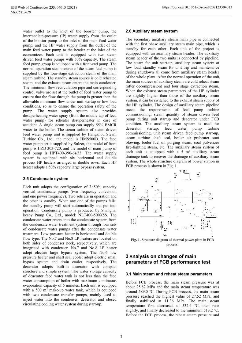
The secondary auxiliary steam main pipe is connected with the first phase auxiliary steam main pipe, which is standby for each other. Each unit of the project is equipped with an auxiliary steam header. The auxiliary steam header of the two units is connected by pipeline. The steam for unit start-up, auxiliary steam system at low load, standby steam for unit trip and maintenance during shutdown all come from auxiliary steam header of the whole plant. After the normal operation of the unit, the main sources of auxiliary steam are cold reheat steam (after decompression) and four stage extraction steam. When the exhaust steam parameters of the HP cylinder are slightly higher than those of the auxiliary steam system, it can be switched to the exhaust steam supply of the HP cylinder. The design of auxiliary steam pipeline meets the requirements of feed pump turbine commissioning, steam quantity of steam driven feed pump during unit startup and deaerator under FCB condition. The auxiliary steam system is used for deaerator startup, feed water pump turbine commissioning, unit steam driven feed pump start-up, steam turbine shaft seal, boiler air preheater soot blowing, boiler fuel oil purging steam, coal pulverizer fire-fighting steam, etc. The auxiliary steam system of each unit is equipped with a 5 m3 auxiliary steam drainage tank to recover the drainage of auxiliary steam system. The whole structure diagram of power station in FCB process is shown in Fig. 1.
Fig. 1. Structure diagram of thermal power plant in FCB
process.
3 Analysis on changes of main parameters of FCB performance test
3.1 Main steam and reheat steam parameters
Before FCB process, the main steam pressure was at about 25.82 MPa and the main steam temperature was around 589.0 ℃. During FCB process, the main steam pressure reached the highest value of 27.52 MPa, and finally stabilized at 11.36 MPa. The main steam temperature first decreased to 532.4 ℃, then rose slightly, and finally decreased to the minimum 513.2 ℃. Before the FCB process, the reheat steam pressure and
E3S Web of Conferences 233, 04013 (2021)IAECST 2020
https://doi.org/10.1051/e3sconf/202123304013
3
temperature were stable at 5.3 MPa and 601.1 ℃, respectively. After 15 s of FCB process, the reheat steam pressure reached the highest value of 6.3MPa, and then stabilized at about 1.8 MPa. The minimum reheat temperature dropped to 509.4 ℃. In the process of FCB test with 100% loads, the pressure of main steam controlled by bypass decreased rapidly and the temperature of main steam and reheat steam decreases greatly. The main reason for this phenomenon was that the feed water flow was larger than the actual demand. The influencing factors of feed water flow mainly included the disturbance of small turbine steam source switching in FCB process, the regulation characteristics of feed pump turbine, and large drop disturbance of main steam pressure in FCB process.
Fig. 2. Variation curve of main steam and reheat steam
parameters during FCB performance test. (1) Active power of generator, (2) Actual total coal feed, (3) Highest distribution
inlet temperature, (4) Total feed water flow, (5) Front pressure of main steam valve, (6) Outlet temperature of superheater Desuperheater, (7) Reheater outlet temperature, (8) Boiler
master control command.
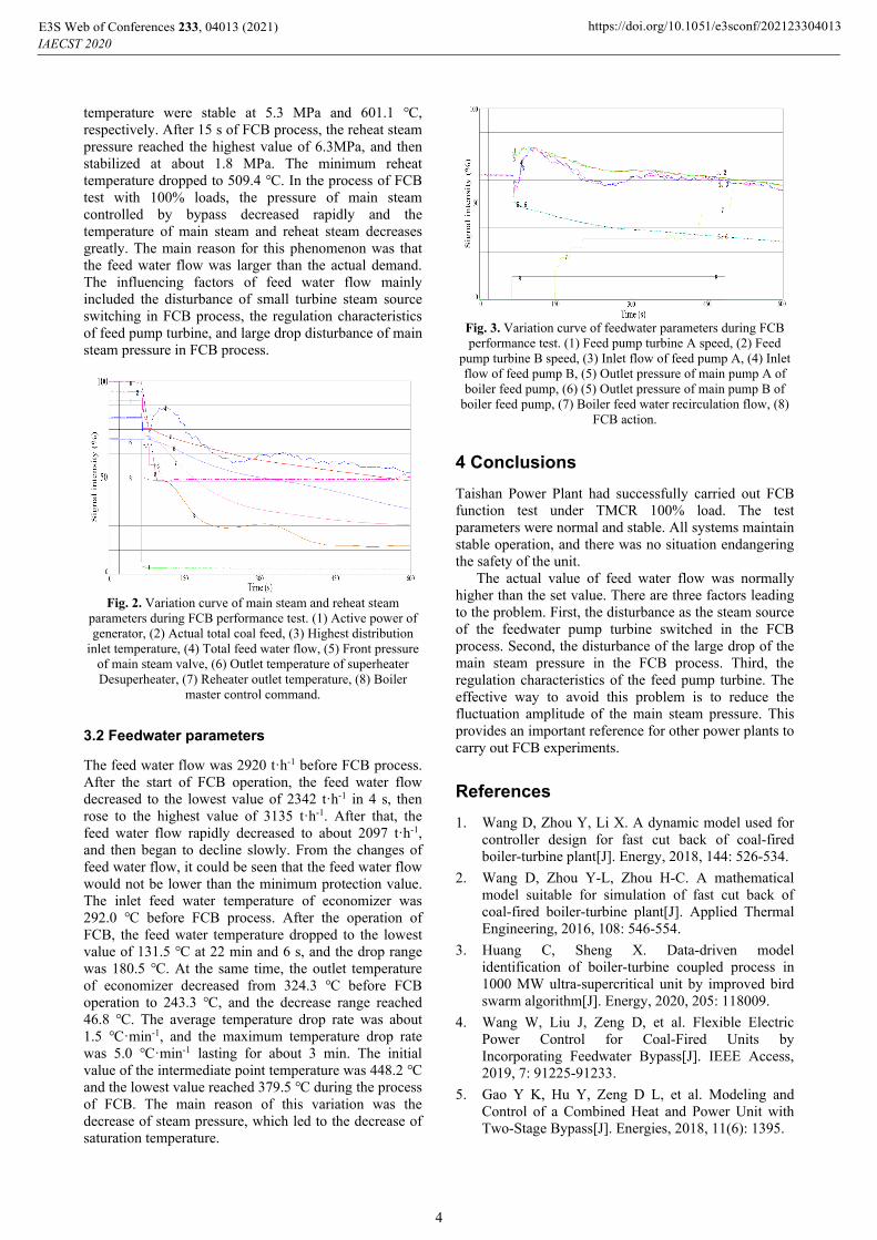
3.2 Feedwater parameters
The feed water flow was 2920 tꞏh-1 before FCB process. After the start of FCB operation, the feed water flow decreased to the lowest value of 2342 tꞏh-1 in 4 s, then rose to the highest value of 3135 tꞏh-1. After that, the feed water flow rapidly decreased to about 2097 tꞏh-1, and then began to decline slowly. From the changes of feed water flow, it could be seen that the feed water flow would not be lower than the minimum protection value. The inlet feed water temperature of economizer was 292.0 ℃ before FCB process. After the operation of FCB, the feed water temperature dropped to the lowest value of 131.5 ℃ at 22 min and 6 s, and the drop range was 180.5 ℃. At the same time, the outlet temperature of economizer decreased from 324.3 ℃ before FCB operation to 243.3 ℃, and the decrease range reached 46.8 ℃. The average temperature drop rate was about 1.5 ℃ꞏmin-1, and the maximum temperature drop rate was 5.0 ℃ꞏmin-1 lasting for about 3 min. The initial value of the intermediate point temperature was 448.2 ℃ and the lowest value reached 379.5 ℃ during the process of FCB. The main reason of this variation was the decrease of steam pressure, which led to the decrease of saturation temperature.
Fig. 3. Variation curve of feedwater parameters during FCB performance test. (1) Feed pump turbine A speed, (2) Feed
pump turbine B speed, (3) Inlet flow of feed pump A, (4) Inlet flow of feed pump B, (5) Outlet pressure of main pump A of boiler feed pump, (6) (5) Outlet pressure of main pump B of
boiler feed pump, (7) Boiler feed water recirculation flow, (8) FCB action.
4 Conclusions
Taishan Power Plant had successfully carried out FCB function test under TMCR 100% load. The test parameters were normal and stable. All systems maintain stable operation, and there was no situation endangering the safety of the unit.
The actual value of feed water flow was normally higher than the set value. There are three factors leading to the problem. First, the disturbance as the steam source of the feedwater pump turbine switched in the FCB process. Second, the disturbance of the large drop of the main steam pressure in the FCB process. Third, the regulation characteristics of the feed pump turbine. The effective way to avoid this problem is to reduce the fluctuation amplitude of the main steam pressure. This provides an important reference for other power plants to carry out FCB experiments.
References
1. Wang D, Zhou Y, Li X. A dynamic model used for controller design for fast cut back of coal-fired boiler-turbine plant[J]. Energy, 2018, 144: 526-534.
2. Wang D, Zhou Y-L, Zhou H-C. A mathematical model suitable for simulation of fast cut back of coal-fired boiler-turbine plant[J]. Applied Thermal Engineering, 2016, 108: 546-554.
3. Huang C, Sheng X. Data-driven model identification of boiler-turbine coupled process in 1000 MW ultra-supercritical unit by improved bird swarm algorithm[J]. Energy, 2020, 205: 118009.
4. Wang W, Liu J, Zeng D, et al. Flexible Electric Power Control for Coal-Fired Units by Incorporating Feedwater Bypass[J]. IEEE Access, 2019, 7: 91225-91233.
5. Gao Y K, Hu Y, Zeng D L, et al. Modeling and Control of a Combined Heat and Power Unit with Two-Stage Bypass[J]. Energies, 2018, 11(6): 1395.
E3S Web of Conferences 233, 04013 (2021)IAECST 2020
https://doi.org/10.1051/e3sconf/202123304013
4