Embed Size (px)
Citation preview
fc o o o o o 1 a ^™"r *'
WARZYN
Report Work Plan12688 Electro-Voice Site
Remedial Investigation/Feasibility Study
Buchanan, Michigan
Prepared for:Michigan Department Of Natural Resources
Lansing, Michigan
Prepared by:Warzyn Engineering Inc.
Detroit, Michigan
OCTOBER 1987
WARZYN
Work PlanElectro-Voice Site
Remedial Investigation/Feasibility Study
Buchanan, Michigan
TABLE OF CONTENTS
PAQEREMEDIAL INVESTIGATION
INTRODUCTION ............................................................. 1
TASK 1: SITE DESCRIPTION AND PREVIOUS INVESTIGATIONSSite Background ...................................................... 1Geology .............................................................. 4Topography ........................................................... 5Hydrogeology and Hydrology ........................................... 5Socioeconomic ........................................................ 6Previous Site Investigations ......................................... 6Previous Remedial Actions ............................................ 8Assessment of Existing Information and identification of Data
Requirements ....................................................... 8
TASK 2: PROJECT PLANS ................................................... 9Subtask 2.1 - Work Plan Preparation .................................. 9Subtask 2.2 - Quality Assurance Project Plan ......................... 10Subtask 2.3 - Sampling Plan .......................................... 11Subtask 2.4 - Health & Safety Plan ................................... 12
TASK 3: SITE INVESTIGATION .............................................. 13Subtask 3.1 - Preliminary Site Evaluation ............................ 13Subtask 3.2 - Existing Well Sampling ................................. 15Subtask 3.3 - Site Base Map .......................................... 16Subtask 3.4 - Site Operations Preparation ............................ 16Subtask 3.5 - Soil Boring and Well Installation ...................... 17Subtask 3.6 - Groundwater Sampling and Aquifer Testing ............... 22Subtask 3.7 - Groundwater Level Monitoring ........................... 23Subtask 3.8 - Location and Elevation Survey .......................... 24
TASK 4: COMMUNITY RELATIONS SUPPORT ..................................... 24
TASK 5: REMEDIAL INVESTIGATION REPORT ................................... 24
TASK 6: DATA ASSESSMENT AND VALIDATION .................................. 25
TASK 7: RI PROJECT MANAGEMENT ........................................... 25
WARZYN

TABLE OF CONTENTS(continued)
PA6E
FEASIBILITY STUDY
TASK 8: WORK PLAN REVISION AND DESCRIPTION OF PROPOSED RESPONSE ........ 26
TASK 9: ENDANGERMENT ASSESSMENT ........................................ 26
TASK 10: PRELIMINARY REMEDIAL TECHNOLOGIES .............................. 27
TASK 11: DEVELOPMENT OF ALTERNATIVES .................................... 27Subtask 11.1 - Establishment of Remedial Response Objectives ......... 27Subtask 11.2 - Identification of Remedial Alternatives ............... 28
TASK 12: INITIAL SCREENING OF ALTERNATIVES .............................. 29
TASK 13: NOTIFICATION OF STATE ARARs .................................... 30
TASK 14: DETAILED ANALYSIS OF THE ALTERNATIVES .......................... 30Subtask 14.1 - Technical Analysis .................................... 30Subtask 14.2 - Environmental Assessment .............................. 31Subtask 14.3 - Public Health Analysis ................................ 31Subtask 14.4 - Institutional Analysis ................................ 32Subtask 14.5 - Cost Analysis ......................................... 32
TASK 15: EVALUATION OF COST-EFFECTIVE ALTERNATIVE ....................... 32
TASK 16: PRELIMINARY REPORT ............................................. 33
TASK 17: FINAL REPORT ................................................... 34
TASK 18: FEASIBILITY STUDY PROJECT MANAGEMENT ........................... 34
L1st of References ....................................................... 35
[ELE AA1]
WARZYN

LIST OF TABLES
Table 1 Summary of On-Site Monitoring Well Boring LogsTable 2 Top of Casing and Static Water Level Elevations for On-Site
Monitoring Wells
Table 3 Summary of Off-Site Boring LogsTable 4 Previous Electro-Voice Sampling Results: North LagoonTable 5 Water and Bottom Sludge Analysis: North and South LagoonsTable 6 Summary of Monitoring Well Analyses
Table 7 Proposed Phase I Monitoring Well Locations and Rationale
Table 8 Summary of RI Field Activities
LIST OF FIGURES
Figure 1 Site Location Map
Figure 2 Site MapFigure 3 Disposal Lagoons Core Sampling Log
Figure 4 Prior Disposal Lagoons and Locations of Existing Monitoring Wells
Figure 5 Groundwater Surface Contours and FlowFigure 6 Phase I Monitoring Well Locations
Figure 7 Typical Well Construction
A-l
A-2
B
[ELE AA1]
LIST OF APPENDICES
Warzyn Engineering Preliminary Cost Estimates
Engineers International Preliminary Cost EstimatesProject Schedule
WARZYN

INTRODUCTIONThis Work Plan describes the activities to be performed in a RemedialInvestigation/Feasibility Study (RI/FS) of the area presently occupied byElectro-Voice, Inc. The site 1s located 1n Buchanan, Michigan, approximatelysix miles west of Niles, Michigan {Figure 1). This Work Plan Includes a briefhistory of the problem, past remedial measures and studies performed at thesite, a detailed description of proposed Investigations to be performed, and adiscussion of the work tasks associated with the development and selection ofremedial alternatives. Budgets for Warzyn Engineering Inc. and itssubcontractors are attached In Appendices Al and A2. A project schedule isprovided in Appendix B. The Work Plan has been prepared in fulfillment ofMichigan Department of Natural Resources (MDNR) Contract Number 3644.
The purpose of the Remedial Investigation (RI) 1s to examine the nature andextent of environmental contamination at the study site. A variety of fieldactivities are proposed for this purpose. The RI will be conducted in such amanner as to gather data necessary to support the Feasibility Study (FS).During the FS, alternatives will be developed and evaluated for remediation ofthe site.
ObjectivesThe, primary objectives of the Remedial Investigation are to:
. Evaluate the nature and extent of environmental contamination;
. Evaluate the threat of contamination to the public health;
. Provide data adequate for performance of a Feasibility Study.
The objective of a Feasibility Study is to develop, evaluate and select remedialmeasures for mitigating any environmental hazard caused by contamination in thisarea, should this be Identified.
TASK 1: SITE DESCRIPTION AND PREVIOUS INVESTIGATIONSSite BackgroundElectro-Voice, Inc. Is a manufacturing company involved in electroplating andthe production of sound equipment. The plant 1s located in southwestern
WARZYN

Work Plan -2- October, 1987C 12688
*
Michigan, on the southern edge of the City of Buchanan, Berrien County,approximately six miles west of N1les, Michigan (Figure 1). This is within theNW 1/4 of Section 36, Township 7 South, Range 18 West.
Data pertaining to early history of the site 1s incomplete. The originalbuilding at the site was constructed in approximately 1902. From the late1920's to the early 1930's, Campbell Transmissions Company was in operation atthe site. The property and facility was then purchased by the Dry ZeroCorporation, which produced Insulating materials, and operated here from themid-1930's to 1940. Clark Equipment, which manufactured transmissions for largeequipment, leased and utilized the facility from 1940-1946. In 1946, Electro-Voice, Inc. purchased the property and began operations. Electro-Voice is thepresent owner and operator of the facility.
Past records indicate that the first use of the site was as a municipally-ownedopen dump. From the 1920's through the early 1940's various property owners inthe area utilized the back portion of the Electro-Voice property for a dump.The miscellaneous debris and fill material which was dumped here resulted inproperty expansion to the west. The area in which the lagoons were located 1sbuilt entirely on fill material, and contains the rubble from several razedbuildings from the City of Buchanan. South of the Electro-Voice property therehave in the past been both gravel pits, used subsequently as an open dump, and abulk oil unloading terminal servicing the Westvllle Oil Company processingplant, which occupied the western edge of the lagoon area (TenEch, 1980).Therefore, portions or all of the existing Electro-Voice plant are presentlylocated on miscellaneous and unknown fill material.
In 1946, when the property was owned by Clark Equipment Company, two claylagoons (north and south) were constructed at the site for disposal of liquidwastes of unknown content. These were located just west of the present building(Figure 2). The lagoons were connected in series by a 12-inch corrugated metaloverflow pipe, the north lagoon being the primary discharge lagoon. The north
WARZYN
Work Plan ' -3- October, 1987C 12688
lagoon was approximately 50 feet 1n diameter and eleven feet deep, with verysteeply sloped sides. The Inlet to the lagoon was a three-foot wide ditchentering from the southeast. From 1952-62, Electro-Voice discharged metalplating waste to the north lagoon. Past Information supplied by plant personnelIndicates that this lagoon was continuously filled with standing water (TenEch,1979).
A 12-inch diameter corrugated metal pipe set at approximately eight and one-halffeet above the north lagoon bottom served as an overflow to the secondary(south) lagoon. This lagoon was approximately 45 by 75 feet, and 10 feet deep.Plant personnel Indicate that no overflow has ever occurred from the first tothe second lagoon. This 1s supported by the fact that prior to abandonment,this lagoon was largely overgrown by vegetation (TenEch, 1979).
Both the north and south lagoons were lined with an 8-Inch bentonite clay layer(Figure 3). Use of these lagoons was discontinued In 1962 due to theInstallation of a new waste water treatment facility at the site.
In 1979, Electro-Voice hired TenEch Environmental Consultants, Inc. to develop aprogram for removal and abandonment of the two lagoons. In January 1980 fourmonitoring wells were Installed around the lagoons to determine 1f liquid wasteshad leaked from the lagoons, thereby contaminating groundwater in the area(Figure 4). Analysis of groundwater samples taken from the four wells (January1980) Indicated the presence of xylene and toluene In well #2 and well #3.Elevated lead concentrations were also noted In all 4 wells (Table 6).
Other samples were collected during investigation of the lagoons. This Includedsludge and standing water within the lagoons. Analysis of these samplesindicated the presence of elevated levels of heavy metals in both media, andcyanide in water samples (Tables 4 and 5).
In September 1980 the north lagoon was removed. This Included the removal ofapproximately 15,000 gallons of water; 19,600 gallons of sludge, and 40 cubic
WARZYN

Work Plan -4- October, 1987C 12688
yards of clay Uner. These materials were disposed of off-site, and the areawas then filled with clean fill and graded (TenEch, 1980). The South lagoon wasnot considered a problem and was not removed, but was filled and graded levelwith the surface topography of the area. The rationale for this action was thatthe south lagoon had never been used for disposal purposes.
GeologyThe site 1s located 1n an area underlain by glacial moraines and glacialoutwash. This area 1s characterized by gently sloping topographic relief,altered by modern gravel pit and dumping operations. Topographic relief withinone-half mile of the site 1s approximately 100 feet. Quarternary deposits inthis region of Michigan range from 100 to 400 feet 1n thickness.
The site surfldal material 1s classified In the Oshtemo Series (SoilConservation Service, 1980). This series 1s characterized by well drained soilsformed in loamy and sandy glactofluvial deposits. Soils in the upper five feetvary but are typically reddish-brown loam to loamy sand. The underlain material1s loose stratified course sand and fine gravel. Thickness of the upper soilprofile ranges from 40 to 63 Inches. The site quarternary deposits areunderlain by the K1nderhook1an Series Coldwater Formation. The Coldwater Shalebedrock formation 1s a blue-gray to green shale with sandstone and limestonelenses.
Previous Investigations at the site provide specific Information about geologyof the area (TenEch, 1979, 1980). As shown on Table 1, well boring logs for thefour on-s1te monitoring wells Indicate that the upper 40-50 feet of material 1scharacterized by sand and gravel. Off-site private wells support thisobservation, as identified on Table 3. Also indicated on Table 3 is thepresence of two thick, blue clay layers under the surface sand and graveldeposits. The thickness of the upper clay layer appears to vary from 11 to 37feet, while that of the lower clay layer ranges from 44 to 51 feet.
WARZYN

Work Plan -5- October, 1987C 12688
TopographyThe Electro-Voice building lies at an elevation of approximately 740 feet MSL(USGS, 1980). The area west of the Electro-Voice building, where the on-s1telagoons were located, 1s a depression with an elevation of approximately 720feet MSL. An approximately 20 foot high slope separates the Electro-Voicebuilding and grounds from the depressional area (Figure 4). When present, thenorthern lagoon was about eleven feet deep, and the southern lagoon about 10feet deep.
A number of gravel pits are located south of the Electro-Voice plant, creatingmoderate elevation variations In this area (Figure 1). The .elevation of nearbyMcCoy Creek is 695 MSL.
HvdroQeoloQV and HydrologyPreliminary Investigations Indicate that regional groundwater flow 1s to thenorth toward the St. Joseph River. Local flow beneath the study area appears tobe northwest toward McCoy Creek (Table 2 and Figure 5). This creek feeds theSt. Joseph and 1s located approximately 2,200 feet northwest of the old lagoonarea. The depth to groundwater at the site ranges from 33 to 40 feet in thedepressional area where the lagoons were previously located. Surface runofffrom the site which 1s not captured by storm sewers and drains to thisdepressional area.
Permeability of the Oshtemo soils at the site are moderate to very rapid. Thisrange 1s from 2 to 20 Inches/hour. These surficial soil materials are underlainby approximately 200 feet of quarternary glacial deposits which Include anunknown number of aquifers. The upper portion of the glacial material (5-40feet) comprises the upper unconfined aquifer In the area. This aquifer containsfine to coarse sand and gravel, which 1s typical of glacial outwash deposits.
Wells In the glacial outwash area are typically finished at about 40-45 feet andyield sufficient production (Buchanan County Health Department, Ken Priest,February 1987). However, no Information has been obtained regarding the pumping
WARZYN

Work Plan -6- October, 1987C 12688
rates of local wells. THe nearest well draw-ing from the shallow aquifer 1s theWerrback Residence (1165 Wilson Lane) at a distance of approximately 0.5 milesnorthwest of the site (Figure 3). The City of Buchanan well field consists offour wells located about 0.6 miles west of the site. These wells are located Inthe glacial outwash and are completed at a depth of about 40 feet. Static waterlevels correspond closely to the elevation of HcCoy Creek (695 feet MSL) andIndicate hydraulic connection between the creek and the upper unconfinedaquifer.
SocioeconomlcA variety of land uses exist 1n the Electro-Voice vicinity. Considerablehousing exists in the area, particularly north and west of the site. Land tothe south 1s largely undeveloped and exists as gravel pits. Some commercialproperties are located to the west of the site, and a public school lies justnortheast.
Approximately 5,142 people within a three-mile radius of the study site wereidentified as being on private wells In 1983, and an additional 4,765 in thesurrounding community (MDNR, 1983). It 1s not known how many of these residentsare now supplied by the municipal water system. The majority of residents inthe immediate Electro-Voice area, however, are believed to be using municipalwater.
Previous Site InvestigationsIn March 1979, as a result of a ruptured drain pipe carrying wastes to theplant's on-site treatment facility, plating waste solution was released Into thenorth lagoon. Electro-Voice reported this Incident to the MDNR, which beganinvestigation of the facility shortly after the incident was reported. The MDNRrequested a review of the existing on-site plating waste treatment facility andconducted an Inspection of the Electro-Voice facility on March 29, 1979. TheMDNR was satisfied with the efforts made by Electro-Voice In response to theproblem and clean-up.
WARZYN
Work Plan -7- October, 1987C 12688
On September 25, 1979, the MONR conducted an on-site Inspection of the Electro-Voice spill containment program. During the Inspection the MDNR noted thatsmall amounts of plating room wastes were discharged to a floor drain, which ledto a small pond via an open earthen ditch. The exact location of the pond andditch have yet to be Identified. The MDNR requested the following actions betaken by Electro-Voice:
Installation of a temporary holding tank to collect floor drainwater.
Submlttal of a design and program for a permanent drainagecollection system in order to update the existent treatmentprogram.Preparation of a groundwater monitoring program.
Electro-Voice complied with these requests.
In 1979, TenEch Environmental Consultants were hired by Electro-Voice to assessexisting conditions related to the waste disposal lagoons. Groundwatermonitoring of the four on-site wells began 1n January 1980. The groundwateranalytical results generally showed no metal contamination in any of the fourwells, Indicating plating wastes had not leaked from the lagoons Into thegroundwater. Elevated levels of lead were noted in all wells, however, andwells #2 and #3 had elevated levels of xylene and toluene (Table 4J. The sourceof these organic contaminants 1s unknown.
On July 29, 1982, a Hazard Ranking System Assessment was conducted at Electro-Voice. In a memo/report dated February 28, 1983, Ecology and Environment Inc.conducted a potential hazardous waste site preliminary assessment of Electro-Voice. In 1983, Electro-Voice was placed on the Michigan and Federal Superfundlists. In the June 1986 National Priority List Fact Book. Electro-Voice Isranked Number 491, Group 10 as of December 1982. In the February 1987 MichiganSites of Environmental Contamination Priority Lists (Act 3071 Book, Electro-Voice received a score of 610, Group 1 (09-27-84).
WARZYN
Work Plan -8- October, 1987C 12688
Previous Remedial ActionsTo date, no remedial actions have been undertaken In regard to the organicgroundwater contamination problem. However, Electro-Voice has performed severalremedial actions related to the March 1979 waste pipe rupture. These Include:
Installation of a temporary, followed by a permanent, holding tankto collect drainage waste (final tank Installed November 1979).
Submittal of a design and program for updating the existent wastetreatment facility.
Submlttal, approval, Installation and Implementation of agroundwater monitoring program. (Four wells were Installed byJanuary 14, 1980).
So1l/I1ner, water and sludge samples from the lagoons were takenand analyzed.
As of September 1980, the north lagoon was removed. RemovalIncluded disposal of standing water; disposal of sludge; excavationand disposal of the clay liner; and grading, filling and compactionof the excavated area. Surface topography Is level with thesurrounding area topography.As of September 1980 the south lagoon, left Insltu, was graded,filled and compacted level with the surface topography of the area.
Assessment of Existing Information and Identification of Data RequirementsAlthough some Information on the Electro-Voice contamination problem 1savailable, further Investigation Is .necessary to more clearly assess the currentsituation and Identify potential on-s1te source areas.
The following Items Identify what 1s currently known about the site, and wheredata gaps exist.
Considerable fill material of unknown composition 1s present withinthe study area. At least a portion of the existing Electro-Voicebuilding 1s constructed on such fill. The depressed area in whichthe two discharge lagoons were once present may also contain fillmaterial.
Other potential groundwater contamination source areas exist 1nareas surrounding the site. In particular, an old city dump liesapparently upgradlent of the site. Therefore, there 1s apossibility of cross contamination. »*«»«*»•VUnRZYN

Work Plan -9- October, 1987C 12688
Groundwater flow direction at the site appears to be In anorthwesterly direction. This has not been well documented,however, and needs further Investigation.Depth to groundwater at the site appears to be about 33-40 feetbelow ground surface In the depressional area.Soil composition In the depressional area appears to be mixed sandand clay to about 35-45 feet below ground surface, underlain by 5feet of gravel. Off-site well logs Indicate thick clay layers atabout 40-50 feet below ground surface.
Analysis of bottom sludge prior to lagoon removal and abandonmentIndicated the presence of heavy metals. No heavy metalcontamination (except lead) has been noted 1n groundwater.
Two of the four monitoring wells Installed around the previouslyexisting lagoon (wells #2 and #3) Indicate elevated organiccontaminants (xylene, toluene, TOC). The source of thesecontaminants Is presently unknown. A "rotten garbage" odor wasalso noted during previous sampling of these wells.
Recent groundwater quality data (late 1986) for the City ofBuchanan municipal water supply wells Indicates no contamination.These wells are located about one-half mile west of Electro-Voice.
TASK 2: PROJECT PLANSThe various planning documents necessary for the performance of the RemedialInvestigation and Feasibility Study (RI/FS) will be prepared under Task 2.These plans will function as working documents which provide structure to theIdentified work tasks, while also allowing for modifications in the field, asrequired. All plans, as listed below, will be approved by MDNR and the U.S.Environmental Protection Agency (U.S. EPA), as appropriate, before work onsubsequent tasks or subtasks can occur.
. Work PlanQuality Assurance Project PlanSampling PlanHealth and Safety Plan
Subtask 2.1 * Work Plan PreparationThis Work Plan describes the various work tasks to be performed during the RI/FSproject. The Work Plan was developed upon Information obtained through reviewof existing data (as referenced In Task 1), discussions with MDNR staff, and thesite visit.
WARZYN

Work Plan -10- October, 1987C 12688
U.S. EPA guidance documents for performance of Remedial Investigations andFeasibility Studies were considered in the development of this work plan. WorkPlan tasks have been developed In consideration of Section 121 of the SuperfundAmendments and Reauthorization Act (SARA). In addition to a detailed technicaldescription of tasks to be performed In the Electro-Voice RI/FS, a projectedcost estimate for the Investigation and project timetable are also included(Appendix A).
MDNR and U.S. EPA review comments on the Draft Work Plan have been consideredand Incorporated Into the Final Work Plan.
Subtask 2.2 - Quality Assurance Pro.lect PlanA Quality Assurance Project Plan (QAPP) will be developed for all field samplingand analytical activities, laboratory analytical work, and data handling aspectsof the Remedial Investigation.
The QAPP will be consistent with U.S. EPA Region V guidance documents and willaddress the following considerations:
Project description;
Project Quality Assurance (QA) organization and responsibility;QA objectives for measurement data in terms of precision, accuracy,completeness, representativeness, and comparability;Sampling objectives and procedures;
Sampling custody;Calibration procedures, references, and frequency;Analytical procedures and methods;
Data reduction, validation and reporting;
Internal QC checks and frequency;QA performance audits, system audits, and frequency;
QA reports to management;
WARZYN

Work Plan -11~ October, 1987C 12688
Preventive maintenance procedures and schedules;
Specific procedures to be used to assess data precision,representativeness, comparability, accuracy, and completeness;Corrective action.
Review comments on the Draft QAPP from MDNR and U.S. EPA will be considered andincorporated into the final version of the QAPP.
Subtask 2.3 - Sampling PlanThe Sampling Plan 1s an Integral part of the QAPP, and will be Included in thatdocument. The Sampling Plan will address the following sampling factors:
Sample location;Specific sampling procedures;Sampling program operation (types, parameters, frequencies);Specific collection and packaging materials;Special conditions for preparation of materials;Sample preservation methods and times;Shipping considerations;Chaln-of-custody procedures;Sample documentation;Analytical arrangements;Scheduling.
Review comments on the Draft Sampling Plan for MDNR will be considered andincorporated Into the final version of the Sampling Plan.
The Sampling Plan will be developed in accordance with applicable U.S. EPAguidance documents. Review comments from the MDNR and U.S. EPA on the DraftSampling Plan will be considered and Incorporated Into the Final Sampling Plan.U.S. EPA will solicit comments from the Agency for Toxic Substances and DiseaseRegistry (ATSDR) to assure, to the extent practical, that their data needs forconducting a health assessment at the site are met within the scope of theSampling Plan.
WARZYN

Work Plan -12- October, 1987C 12688
Subtask 2.4 • Health and Safety PlanA site-specific Health and Safety Plan will be developed to address hazards thatinvestigative activities may be present to the Investigation team and thesurrounding community. The plan will address all applicable regulatoryrequirements and detail personnel responsibilities, protective equipment,procedures and protocols, decontamination, training, and medical surveillance.Problems or hazards that may be encountered, and their solutions, will beidentified. Procedures for protection of third parties, such as visitors orsurrounding community, will also' be provided. The plan will be consistent withthe following documents, and address site-specific conditions:
Section III(c)(6) of CERCLA (Comprehensive Environmental Responses,Compensation, and Liability Act of 1980)
U.S. EPA Order 1440.2 - Respiratory Protection
U.S. EPA Order 1440.3 - Health and Safety Requirements forEmployees Engaged 1n Field ActivitiesU.S. EPA Occupational Health and Safety Manual
U.S. EPA Standard Operating Safety Procedures
Michigan Occupational Health and Safety Administration
The Health and Safety Plan will Include an assessment to determine If there areportions of the site or specific investigation activities that presentpotentially hazardous exposure levels to site personnel as a result of airborneor dermal contact. Investigation activities will be designed to minimizehazards to the investigating team.
In conducting the health and safety assessment, available Information on thesite will be examined and reviewed to Identify potential hazards. Suchinformation will be used in selecting and implementing procedures that providenearby residents and Investigators with adequate warnings and safeguards. TheSafety Plan will specify the following:
WARZYN
Work Plan -13- October, 1987C 12688
Protective clothing and respiratory equipment to be worn;
Air monitoring to be performed;
Action levels at which respiratory protection will be upgraded;Decontamination procedures.
The Health and Safety Plan will be developed 1n accordance with all applicableU.S. EPA guidance documents and requirements. Applicable Occupational Healthand Safety Administration (OSHA), Michigan Occupational Health and SafetyAdministration (MOSHA), and National Institute for Occupational Safety andHealth (NIOSH) requirements will be followed. Review comments from HDNR andU.S. EPA on the Draft Health and Safety Plan will be considered and Incorporatedinto the Final Health and Safety Plan.
TASK 3: SITE INVESTIGATIONSubtasks 3.1 through 3.8 Identify the specific field activities which will beperformed during the Remedial Investigation. A summary of these tasks 1sprovided 1n Table 8.
Subtask 3.1 - Preliminary Site EvaluationAlthough some Information Is currently available regarding the Electro-Voicesite area, additional data .would be useful in making Informed decisionspertaining to the site Investigation. Information will therefore be obtainedfrom available records and Interviews with local residents. On-slte Inspectionsof areas will be performed when this may yield useful information. Specialattention will be given to past practices regarding disposal, storage, materialusage, and process operations. Such Information will aid in determining thesuitability of existing wells for use in a sampling program. The scope of thisInvestigation will be limited to the Electro-Voice area. Information gatheringefforts related to off-site areas will be limited and cursory. Informationobtained from these Investigations may Impact the final scope of activities tobe performed in the site Investigation.
WARZYN

Work Plan -14- October, 1987C 12688
The primary objective of this task will be to Identify potential on-site sourceareas which may be contributing to monitoring well contamination. The followingareas have presently been Identified as of Interest In this regard:
An on-site area (Electro-Voice) where an old steel tank wasoriginally located. The tank was used to store paint waste andsolvents, and was removed 1n 1979, when it was replaced with afiberglass tank.
On-site fill material, upon which all or portions of Electro-Voiceare now located.
Activities related to the operations of preceding companies at theElectro-Voice location (I.e., Dry Zero Industries and ClarkEquipment).
Additionally, other potential contamination source areas appear to exist in thesurrounding community. Therefore, there Is a need to perform data gatheringefforts and off-site surveys 1n selected areas. The secondary objective of thisInvestigative task will be to obtain some Information related to certainpotential off-site source areas which may be contributing to the monitoring wellcontamination problem previously Identified at Electro-Voice. This includes:
An old city dump dating back to the early 1900's. This appears tohave been an uncontrolled dump site. The dump site 1s locatedabout one-quarter mile southeast of Electro-Voice.
•The operation of an old refinery to the west of Electro-Voice.A bulk oil unloading terminal servicing the Uestville 011Processing Plant.
Assumptions for the cost estimate for this subtask are as follows:
Surveys will require two people for a single three day trip;MDNR will arrange with the industries, commercial participants, andthe municipality for the site survey;Three Industries will be surveyed; the city dump records will beexamined; a one-day historical literature search will be conducted.
WARZYN
Work Plan -15- October, 1987C 12688
•Subtask 3.2 - Existing Well SamplingSampling of existing residential, commercial, and municipal wells within anapproximate one-half mile radius from the study site will be conducted by MDNRduring the Initial stages of the site Investigation. In addition, the fourexisting monitoring wells at the site will also be sampled. The purpose of thiseffort is to provide Information on existing groundwater quality conditionswithin the general site area, which should enable a better assessment ofpotential areas of contamination and sources and help to locate monitoringwells. The condition and suitability of residential wells for water qualitysampling is presently unknown, and therefore will be determined prior tosampling, during Subtask 3.1.
Samples collected will be analyzed for CLP inorganics (metals and cyanide),acid/base neutral extractable organics, volatile organic compounds (VOCs),polychlorlnated biphenyls (PCBs)/pest1c1des by routine analytical service (RAS)within the contract laboratory program (CLP). Samples will also be analyzed forgeneral Indicator parameters as listed below:
pH (field and lab) Nitrate NitrogenConductivity (field) Total KJeldahl nitrogenTemperature (field) Ammonia NitrogenAlkalinity TOC (total organic carbon)Chloride SulfateBOD COD (chemical oxygen demand)Dissolved Phosphorus Hexavalent Chromium
The number and location of private and commercial wells in proximity to theElectro-Voice site 1s presently unknown. Based on the number of residences andbusinesses In the Immediate area, 1t is assumed that this subtask will involvethe sampling of a maximum of 10 residential wells and 3 commercial wells. Thiswill include the two deep wells identified east of the study area (Table 3).Exact sampling and analytical procedures will be described in the QAPP andSampling Plan.
WARZYN
Work Plan -16- ' October, 1987C 12688
Assumptions for this subtask are as follows:
Two day period to perform;Level D protection will be worn;
Ten residential wells, 3 commercial wells, 2 municipal wells, and 4monitoring wells (on-s1te) will be sampled;
HNu monitoring will be required;Groundwater samples will have low contamination concentration.
The HDNR will be responsible for coordinating and performing all activitiesassociated with this subtask.
Subtask 3.3 • Site Base HaoA r-200' site base map will be prepared of the study area. The map will bedeveloped using aerial photographs of the site and surrounding area. Allpertinent site features (Including monitoring wells, sampling locations, surfacewater bodies, drainage patterns, relic lagoons area, roadways, building anddisposal areas) will be surveyed for location and elevation. A 2-foot contourInterval will be used, with a 5-foot contour used in areas of high relief. Themap will be used as base map when evaluating and designing remedialalternatives.
Aerial photography and preparation of the map will be coordinated and/orperformed by Warzyn. The HDNR will perform the field survey for groundcontrols.
Subtask 3.4 - Site Operations PreparationA site office trailer will be set up as a base of operations for the project.The trailer will be set up on either Electro-Voice property or nearby city-ownedland. It is anticipated that a 10 x 40 foot trailer will be needed, and willremain on-site throughout the Investigation. A secure location will beidentified for the trailer location and storage of well materials. The exact
WARZYN
Work Plan -17- October, 1987C 12688
location of the office trailer and storage area will be coordinated with MDNRand Electro-Voice.
The establishment of a decontamination area, for steam cleaning well materialsand the drilling rig, will be discussed prior to site operations. It Is assumedthat a suitable location can be agreed upon with NDNR for this decontaminationarea to have direct discharge to the city sanitary sewer. Steam cleaning water1s anticipated to have very low or no contaminants due to the low concentrationsin the groundwater.
Assumptions for the cost of this subtask are as follows:
A 10 by 40 ft trailer will be maintained on-site throughout theInvestigation;
Relatively easy access 1s available for Installation of electricand phone utility hookups;
Decontamination waste water will have very low or no contaminantspresent.Disposal of contaminated water to the sanitary sewer Is possible;Two people will be required for a three day period; and
An existing secure location can be Identified by MDNR for storageof well materials and trailer location.
Subtask 3.5 - Soil Boring and Hell InstallationExisting soil boring logs for wells 1n the Electro-Voice area indicate thatglaciofluvlal deposits (sand and gravel) exist in the upper 40-50 feet of thesite (Tables 1 and 3). The majority of wells in the area are finished in thisupper aquifer and yield a good production. Depth to static water ranges from33-41 feet below ground surface for the four monitoring wells (Table 2).
As noted earlier, two deeper wells (130 and 141 feet) exist off-site, east ofthe study area (Figure 1), with static water levels of 45 and 81 feet belowground surface (Table 3). The topographic map for this area Indicates the wells
WARZYN

Work Plan -18- October, 1987C 12688
are at an elevation of approximately 720 MSL, which 1s generally comparable tothe depression*! area where the four existing monitoring wells are located. Asshown In the deep well logs, two relatively thick blue clay layers are presentat about 40-50 feet below ground surface. The thickness of these layersIndicates that they potentially act as aquitards. Therefore, It appears thatany lower aquifers which might be present would be effectively Isolated from theupper contaminated aquifer. Verification of the separation will be accomplishedthrough Subtask 3.2, which will Include sampling of the two private deep wells.
Based on this Information, it 1s not anticipated that any contamination existsbelow the clay layer. Therefore, no wells will be Installed below this depth.Monitoring wells #2 and 13, which Indicate groundwater contamination at thesite, are both 40 feet deep, with static water levels approximately 33-34 feetbelow top of casing (Tables 1 and 2). Therefore, contamination has beenidentified in the upper ten feet of the upper aquifer. Based on the presence ofthe blue clay layer, it 1s not anticipated that a steep vertical groundwatergradient exists in the area. Because toluene, xylene and related organics arelighter than water and often exist as a non-aqueous phase, and given the lowvertical gradient which appears to exist, the occurrence of contaminants isassumed to be restricted to the upper portion of the upper aquifer, at the studysite.
Eight shallow and one deep monitoring well will be Installed within the studyarea, as Indicated on Figure 6. The shallow wells will be placed with thescreens intersecting the water table. This assumes a maximum well depth of 40feet for those 4 wells in the depressional area, and 60 feet for the 3 wells athigher elevation. Screens will be 10-foot stainless steel. Ten foot stainlesssteel risers will be placed above the screens, and the remaining riser footagewill consist of galvanized pipe.
The rationale for shallow well locations is presented 1n Table 7. In general,the wells have been located to accomplish three purposes:
Identify possible contaminants associated with the previous lagoonsat the site;
WARZYN

Work Plan -19- October, 1987C 12688
Identify possible contaminants associated with the fill materialupon which all or a portion of Electro-Voice 1s situated; and
Identify possible contaminants associated with potential on-site oroff-site source areas.
Well locations may vary depending on physical conditions at the site. Hollowstem augers will be used for well drilling. Split-spoon soil sampling will beconducted on all wells. This sampling will be performed at 5-foot Intervals tothe water table. It Is assumed that the unsaturated zone will be about 30 feetthick In the depression area, and 50 feet thick elsewhere. This will accountfor an approximate total of 54 split-spoon soil samples (24 + 30). Additionalsampling will also be performed at changes in Hthology.
Specific soil samples obtained during shallow well Installation will be selectedand sent for analysis. Samples will be analyzed for CLP Inorganics (metals andcyanide), add/base neutral extractable organics, volatile organic compounds(VOCs), polychlorlnated blphenyls (PCBs)/pest1c1des by routine analyticalservice (RAS) within the contract laboratory program (CLP). All samples will bescreened in the field using an HNu or OVA. For those borings which appear toshow contamination, all soil samples will be sent for analysis. For thoseborings which appear to be "clean," 1 or 2 samples will be sent for analysis toconfirm this. Other criteria which will be used for selection soil samples foranalysis Include:
Suspicious appearance - a visual appraisal will be made whenpossible and samples which exhibit unusual or anomalous appearancesmay be selected for analysis.Llthology - In some cases 1t may be pertinent to tracecontamination along a specific horizon, and a sample may beselected based upon Hthology or stratigraphic position.
Based on this criteria, the following assumptions have been made for costestimating purposes:
WARZYN

Work Plan -20- October, 1987C 12688
All soil samples from the 4 wells in the depression area will beanalyzed (total 24 samples).
Two soil samples from the remaining 3 wells will be analyzed (total6 samples).Total soil samples to be analyzed - 30.
One additional "deep" well will also be Installed. This will allow measurementof vertical gradient and water quality sampling from the lower portion of theupper aquifer. This well will be Installed with the screen just above the blueclay layer. The well will be located 1n a nest with the shallow well whichIndicated the greatest evidence (based on HNu readings) for contamination.Therefore, this well will be Installed last, after all other 7 wells have beenplaced. For cost estimation purposes, 1t Is assumed that this well will belocated in the depressional area and will be of 60 feet maximum depth.
One Shelby tube will be taken at the bottom of this deep well. This will enableassessment of the presence of the blue clay layer and analysis for permeability.Additional Shelby tubes may be collected if other clay layers are encountered.This will be a field decision of MDNR and Warzyn.
Well screens and casings will be placed in respective boreholes, and wells willbe finished according to the specifications shown in Figure 8. Well developmentwill be completed using a B-K punp for shallow wells and air development fordeeper wells. Water will be produced from the well until it 1s visually clear,or on-s1te pH and conductivity measurements stabilize.
Warzyn will coordinate and perform all activities associated with this subtask.Assumptions for developing costs for this task are as follows:
A total of 8 wells will be Installed. Seven wells will beInstalled at 7 locations. It Is assumed that 4 wells will beplaced in the depressional area, at a maximum depth of 40 feet, and3 wells in the area of higher elevation, at a maximum depth of 60
WARZYN
Work Plan -21- October, 1987C 12688
feet. One deep well will be Installed (presumably in thedepression area) at a maximum depth of 60 feet. All wells willInclude 10-foot stainless steel well screen, 10-foot stainlesssteel riser and PVC riser pipe;A maximum total of 400 feet of drilling will be conducted;
A total of 54 soil samples will be collected and 30 analyzed;
One Shelby tube will be collected and analyzed for permeability;Well drilling, Installation and development will require 13 fielddays for one drilling rig;Drilling spoils will be drummed and transported to a centralstorage area. Based on subsequent analysis, these will either besent for proper disposal or disposed on-site. MDNR will beresponsible for the analysis and ultimate disposal of thismaterial.Well development water will be contained, so as not to create anuisance, and will be discharged to the city sanitary sewer;MDNR will obtain permits and cover costs, if any, for disposal ofdevelopment water to the city sanitary sewer.The field crew will consist of one geologist, drill crew and onechain-of-custody person;Drilling will be done in Level D protection;
All soil samples will be of low concentration;
HNu monitoring for site safety will be done by the drilling riggeologist.
Due to the somewhat unknown geology of the site area, particularly with regardto the blue clay layer(s), this task has been budgeted to Include additionalactivities beyond those Identified. It 1s assumed that approximately $40,000 ofthe total budget for this task will be utilized for the Identified activities.Additional funds will be used to perform supplemental drilling and wellinstallation. The scope of supplemental services will be agreed upon in a Work
WARZYN

Work Plan -22- October, 1987C 12688
Plan revision based on the results of the prescribed drilling program. It Isanticipated that this supplemental activity will Include the construction ofadditional well nests 1n specific key locations at the site. Specific aspectsof this supplemental drilling program will be identified after the completion ofSubtask 3.5, as identified in this narrative.
Subtask 3.6 - Groundwater Sampling and Aquifer TestingGroundwater samples will be collected from the 8 monitoring wells Installed inSubtask 3.5 and the 10 residential wells, 3 commercial wells, and 3 municipalwells sampled in Subtasks 3.3. These sample results will form a portion of thedata base used for the RI analysis Including:
Source evaluation;Extent of contamination;Estimation of contaminant mass present in groundwater; andThe development of remedial action alternatives.
Prior to sampling, each monitoring well will be purged to remove a minimum ofthree well volumes. A stainless steel bailer or submersible pump will be usedfor performing well purging, and a stainless-steel bailer will be used forsampling. Residential, commercial and municipal wells will be sampled as closeto the well head as practical. Purging and sampling equipment will bedecontaminated before use.
Water purged from the wells will be collected as to not create a nuisance, anddisposed to the city sanitary sewer. Appropriate decontamination procedures andsampling protocol will be specified in the Sampling Plan and QAPP.
Conductivity, temperature and pH of samples will be measured in the field.Samples will be preserved and shipped on Ice to the laboratory dally.Groundwater samples will be analyzed for the general water quality parameterslisted in Subtask 3.2 and CLP Inorganics (metals and cyanide), volatile organiccompounds, acid/base/neutral extractable organ1cs, and PCBs/pesticides. Allparameters will be analyzed by the CLP program.
WARZYN

Work Plan -23- October, 1987C 12688
Bail down tests will be performed at 5 wells using a pressure transducer andHermit data logger. Results from balldown tests will be used to determine thehydraulic conductivity of the aquifer. These wells will be selected based onlocation and boring log Information.
Warzyn will coordinate or perform all activities associated with this subtask.Assumptions for the cost estimate of this subtask are as follows:
A total of 24 wells will be sampled;
Sampling will occur about two weeks after well Installation andwill require a 3-person team. (One crew of two people for samplecollection and one person for sample preparation and chaln-of-custody requirements);Sampling will be done by Warzyn;
Sampling will require two 12-hour days;
Sampling will be conducted at Level D;Monitoring well purge water will be contained and discharged to thecity sanitary sewer for disposal;
Samples will be of low level contamination;
MDNR will obtain permits and cover costs, if any, for disposal ofpurge water to the city sanitary sewer;24 groundwater samples will be collected and analyzed using ERA andstandard methods;
HNu monitoring will be performed;
Hydraulic conductivity testing will require two people for two 12-hour days and will follow groundwater sampling.
Subtask 3.7 • Groundwater Level MonitoringGroundwater levels will be measured in monitoring wells to determine horizontalhydraulic gradients at the site. Water levels will be measured at thecompletion of the well Installation program and concurrent with each groundwatersampling effort. Two additional rounds of water levels will be collected duringthe course of the RI.
WARZYN
Work Plan -24- October, 1987C 12688
HDNR personnel will perform all field activities associated with testing andrecording water levels. Uarzyn will provide Interpretation of data.
Assumptions for this subtask are as follows:
Two separate sets of water levels will be measured between thecompletion of the monitoring well network and the preparation ofthe RI report;Two 12-hour days to perform;
Level D protection.
Subtask 3.8 - Location and Elevation SurveyA location and elevation survey will be performed by HDNR. This survey willinclude pertinent site features (locations and elevations) which may affectgroundwater flow or contaminant distribution, monitoring wells, municipal wells,commercial wells and sampling locations. The map generated in subtask 3.3 willserve as the base map for locating the pertinent features.
TASK 4: COMMUNITY RELATIONS SUPPORTCommunity relation activities are the primary responsibility of MDNR and U.S.EPA. Some support for these activities will be supplied by Warzyn. This will belimited to the participation of one Uarzyn personnel at one public meeting suchas a briefing, press conference, workshop, or public meeting.
TASK S: REMEDIAL INVESTIGATION REPORTA Remedial Investigation (RI) Report will be prepared to summarize and evaluatedata collected during the site investigation and as part of the initialinvestigation activities. The primary emphasis of the RI Report will be todescribe the nature and extent of contamination at the Electro-Voice site. Thereport will address site conditions based upon the matrices investigated (soilsand groundwater). The nature and extent of chemical constituents in each mediumInvestigated will be determined and discussed in the report.
WARZYN
Work Plan -25- October, 1987C 12688
As part of the RI report, a review of QA/QC procedures followed for sampling,analysis and data handling, as required by the approved QAPP, will be prepared.Any limitations on data usage based on deviations from the QAPP, or fromavailable analytical QA/QC Information, will be Identified.
The RI Report will consider all applicable U.S. EPA guidance documents. Thereport will be Issued as a draft within three months of receipt of thegroundwater monitoring data from the last phase of groundwater investigations.The final report will be Issued within one month of receipt of MDNR and U.S. EPAcomments on the draft report.
The probable cost for this task was developed upon the following assumptions:Five copies of the draft report will be Issued to the MDNR andagencies involved. The report 1s assumed to be 300 pages long withten drawings.
Five copies of the final report will be submitted to both MDNR andU.S. EPA. The report Is assumed to be of similar size andcomposition to the draft report.One meeting between representatives of Warzyn, MDNR and U.S. EPAwill be held at MDNR offices 1n Lapsing to discuss draft reviewcomments.
TASK 6: DATA ASSESSMENT AND VALIDATIONData assessment and validation will be the responsibility of Warzyn EngineeringInc. Data validation will follow guidelines in the EPA Technical DirectiveDocument No. HQ-8410-01 for organics analyses and those In Laboratory DataValidation, Functional Guidelines for Evaluating Inorganics Analyses, November,1985, for Inorganics. Warzyn Engineering Inc. will be responsible for examiningdata completeness.
TASK 7: RI PROJECT MANAGEMENTProject management Includes the day-to-day management of the project, schedulingof activities, review of Invoices, subcontractor coordination, and otheradministration duties on the project. Included with this task are Warzyn'sinternal quality assurance/quality control review procedures. It also Includesmonthly project progress summaries and biweekly contacts with the MDNR projectmanager. Invoices will be submitted monthly to MDNR. WARZYN

Work Plan -26- October, 1987C 12688
FEASIBILITY STUDY (FS)
TASK 8 - WORK PLAN REVISION AND DESCRIPTION OF PROPOSED RESPONSEPrior to the completion of the RI, an updated Work Plan for the FS will bedrafted. The Work Plan will outline a revised budget and schedule for FScompletion based on Information obtained during the RI. The approved, updatedWork Plan will be used to direct the remainder of the study. Current U.S. EPAguidances and policies on FS activities will be referenced In the updated FSWork Plan. A draft revision will be submitted to MONR for review and submittalto other appropriate agencies.
A site-specific statement of purpose of the response, based on the results ofthe remedial Investigation, will be presented. The statement will Identify theactual or potential exposure pathways that should be addressed by remedialalternatives. Information on the site background, the nature and extent of theproblem, and previous response activities identified In the RemedialInvestigation may be incorporated by reference,
TASK 9 - ENDANGERMENT ASSESSMENTBased on the results of the Remedial Investigation, an Exposure Assessment willbe prepared. This will be incorporated Into the FS Report and will Include asite evaluation, chemical fate and transport evaluation, basic toxicology, andrisk and exposure assessment. This Information will be combined Into adescription and quantification of actual and potential hazards and risksassociated with the site. The assessment will aid in the determination ofremedial action(s) required to mitigate actual or potential threats to humanhealth, welfare or the environment, and the level to which site cleanup may berequired. The assessment will be in sufficient detail to support an action forrelief through the Federal enforcement process. The Superfund Public HealthEvaluation Manual will be referenced in developing the exposure assessment.
WARZYN
Work Plan -27- October, 1987C 12688
TASK 10 - PRELIMINARY REMEDIAL TECHNOLOGIESA master 11st of potentially feasible technologies will be developed based onthe site-specific problems and statement of purpose Identified earlier. Themaster 11st will be screened (using site conditions, contaminant characteristicsand technical requirements) to eliminate or modify those technologies that mayprove extremely difficult to Implement, will require unreasonable time periods,or will rely on Inappropriate technology. Screening will be done inconsultation with U.S. EPA and MDNR, and in compliance with Section 201 of theSuperfund Amendments and Reauthorization Act (SARA).
TASK 11 - DEVELOPMENT OF ALTERNATIVESBased on the results of the remedial Investigation and consideration ofpreliminary remedial technologies, a limited number of alternatives will beselected and developed.
Subtask 11.1 - Establishment of Remedial Response ObjectivesSite-specific objectives for the response will be established. At a minimum,these objectives will be based on:
• Public health and environmental concerns;• The description of the current situation (from Task 1);• Information gathered during the remedial Investigation;• The requirements of Section 121 of the Superfund Amendments
and Reauthorization Act (SARA) of 1986;
• Section 300.68 of the National Contingency Plan (NCP);
• U.S. EPA's Interim guidance, and the requirements of any otherapplicable U.S. EPA, Federal, and MDNR environmentalstandards; and
• Guidance and advisories as defined under U.S. EPA's CERCLAcompliance policy compendium of May 9, 1985.
Objectives for management of migration measures will be to prevent or minimizeImpacts of contamination that have migrated from the site. Preliminary clean-up objectives will be developed in consultation with U.S. EPA and the MDNR.
WARZYN
Work Plan -28- October, 1987C 12688
Subtask 11.2: Identification of Remedial AlternativesAlternatives will be developed to Incorporate selected remedial technologies,response objectives, and other appropriate considerations Into a comprehensive,site-specific approach. In accordance with Section 300.68(k) of the NCP, atleast one of each of the following types of remedial alternatives shall bedeveloped (to the extent possible and appropriate) as part of the FS:
• Alternatives which utilize permanent solutions and alternativetreatment or resource recovery technologies;
• Alternatives for treatment or disposal at an off-sitefacility;
• Alternatives which employ treatment technologies for reducingtox1city, mobility or volume;
• Alternatives that attain applicable or relevant andappropriate Federal public health and environmentalrequirements (ARARs);
• Alternatives that exceed applicable or relevant andappropriate Federal public health and environmentalrequirements (ARARs);
• Alternatives that do not attain applicable or relevant andappropriate Federal public health and environmentalrequirements, but will reduce the likelihood of present orfuture threat from hazardous substances and that providesignificant protection to public health and welfare and theenvironment. This must Include an alternative that closelyapproaches the level of protection provided by the applicableor relevant and appropriate requirements; and
• No action alternatives.
There may be overlap among the alternatives developed, and alternatives outsideof these categories may also be developed. All alternatives will be developedIn consultation with U.S. ERA and MONR. The rationale for excluding anytechnology Identified in the Preliminary Remedial Technologies task will bedocumented.
WARZYN
Work Plan -29- ' October, 1987C 12688
In developing remedial alternatives, an effort will be made to developalternatives which utilize permanent solutions and alternative treatmenttechnologies. An assessment of such technologies will be made In the FS.Section 121 of SARA recommends these types of alternatives, and stipulates off-site transport and disposal of hazardous substances without such treatment asthe least favorable alternative. Under this regulation, such permanent/alternative treatment alternatives can be selected even if they have not beendemonstrated at other facilities or sites with similar characteristics.
TASK 12 - INITIAL SCREENING OF ALTERNATIVESPrior to undertaking detailed evaluations of the remaining alternatives, thealternatives developed in the preceding task will be screened to eliminate thosethat are infeasible or Inappropriate. Three broad considerations will be usedas a basis for the Initial screening: effectiveness, acceptable engineeringpractice, and cost. The following specific factors, as outlined 1n SARA, willbe considered:
1. Effectiveness
Only those alternatives that satisfy the response objectives andcontribute substantially to the protection of public health, welfare, orthe environment will be given further consideration. The objective ofsource control alternatives will be to achieve adequate control of sourcematerials. Management of migration alternatives will minimize ormitigate the threat of harm to public health, welfare, or theenvironment. Alternatives posing significant adverse environmentaleffects will be excluded.2. Acceptable Engineering Practices
Only alternatives which are feasible for the location and conditions ofthe release that are applicable to the problem, and which represent areliable means of addressing the problem, will be considered further.3. CostAn alternative whose cost far exceeds that of other alternatives willusually be eliminated unless other significant benefits may also berealized. Total costs will Include the costs of Implementing thealternatives and cost of short- and long-term operation and maintenance.
WARZYN

Work Plan -30- October, 1987C 12688
The cost screening will be conducted only after the effectiveness andacceptable engineering practice screenings have been performed.
Alternatives will not be eliminated prematurely on the basis of technology orcost alone.
TASK 13 - NOTIFICATION OF STATE ARARsWhen approximately 25% of the FS Is completed, during the last stages of thepreceding task, the State will be requested to notify Warzyn and the U.S. EPA ofany applicable or relevant and appropriate requirements (ARARs) related toproposed alternatives for the site. The scope of the RI will be evaluated and,if necessary, adjusted to assume compliance with the State ARARs. Asappropriate throughout the RI/FS, the State will update the Identified StateARARs.
TASK 14 - DETAILED ANALYSIS OF THE ALTERNATIVESThe cost-effectiveness of alternative remedies remaining after completion of theInitial screening will be evaluated 1n detail. This evaluation will beperformed 1n the following steps:
Subtask 14.1: Technical AnalysisThe Technical Analysis will, at a minimum:
1. Describe appropriate treatment, storage, and disposal technologies:
2. Discuss how an alternative does (or does not) comply with specificrequirements of other environmental programs. When an alternativedoes not comply, discuss how the alternative prevents or minimizesthe migration of contaminants and public health or environmentalImpacts and describe special design needs that could be Implementedto achieve compliance;
3. Outline operation, maintenance, and monitoring requirements of theremedy;
4. Identify and review potential off-site facilities to evaluatecompliance with applicable RCRA and other U.S. EPA environmentalprogram requirements, both current and proposed. Potential disposalfacilities should be evaluated to determine whether off-sitemanagement of site wastes could result in a potential for a futurerelease from the disposal facility;
Work Plan -31- October, 1987C 12688
5. Identify temporary storage requirements, off-site disposal needs, andtransportation plans;
6. Determine whether an- alternative results In permanent treatment ofdestruction of the contaminant. If not, the potential for futurerelease to the environment for that alternative will be discussed;
7. Outline both on-s1te and off-site health and safety requirements forremedial Implementation;
8. Describe how the alternative could be phased Into Individual operableunits. The description should Include a discussion of how variousoperable units of the total remedy could be Implemented Individuallyor 1n groups, resulting 1n a significant Improvement to theenvironment or cost savings;
9. Describe how the alternative could be segmented Into areas to allowImplementation 1n differing phases, and describe special engineeringrequirements of the remedy or site preparation considerations; and
10. Evaluate engineering Implementation, reliability, andconstructabHlty.
Subtask 14.2: Environmental AssessmentAn Environmental Assessment (EA) will be performed for each alternative. The EAwill focus on site problems and pathways of contamination addressed by eachalternative. The EA for each alternative will Include, at a minimum, anevaluation of beneficial effects of the response/adverse effects of the responseand an analysis of measures to mitigate adverse effects. The no-actionalternative will be evaluated to describe anticipated environmental conditionsif no actions are taken. The no-action alternative will serve as the baselinefor the analysis.
Subtask 14.3: Public Health AnalysisEach alternative will be assessed 1n terms of the extent to which it mitigateslong-term exposure to residual contamination and protects public health, bothduring and after completion of the remedial action. The assessment documentwill characterize on-site contaminants and document concentrations and potentialexposure routes. The effect of "no-action" will be described 1n terms of short-term effects, long-term exposure to hazardous substances, and resulting public
WARZYN
Work Plan -32- October, 1987C 12688
health Impacts. Each remedial alternative will be evaluated to determine thelevel of exposure to contaminants and the reduction in exposure over time. Therelative reduction in Impact will be determined by comparing residual levels ofeach alternative with existing criteria, standards, or guidelines acceptable tothe U.S. EPA. For source control measures or criteria, standards or guidelineswhich are not available, the comparison will be based on the relativeeffectiveness of technologies. The no-action alternative will serve as thebaseline of the analysis.
Subtask 14.4: Institutional AnalysisEach alternative will be evaluated based on relevant Institutional needs.Specifically, regulatory requirements, permits, community relations, andparticipating agency coordination will be assessed.
Subtask 14.5: Cost AnalysisThe cost of each feasible remedial action alternative and each phase or segmentof the alternative will be evaluated. The cost will be presented as a presentworth cost and will Include the total cost of Implementing the alternative andthe annual operating and maintenance costs. Both monetary costs and associatednon-monetary costs will be Included. A distribution of costs over time willalso be provided.
TASK 15 - EVALUATION OF COST-EFFECTIVE ALTERNATIVEThe U.S. EPA and HONR will review the results of the detailed evaluation of theremedial alternatives prepared under the preceding task. In recommending theremedy from among alternatives which achieve adequate protection of publichealth and the environment, the following factors will be considered: cost,technology, reliability, and administrative concerns. The selected remedy 1sgenerally expected to attain or exceed applicable or relevant and appropriatepublic health and environmental requirements.
At a minimum, the following seven Items will be provided to allow a comparisonof alternatives:
WARZYN

Work Plan -33- October, 1987C 12688
1. Present Worth of Total CostsThe net present value of capital and operating and maintenance costs willbe presented.2. Health InformationFor the no-action alternative, a quantitative statement Including a rangeestimate of maximum Individual risk will be provided. Wherequantification 1s not possible, a qualitative analysis may be used. Forsource control options, a quantitative risk assessment will not beprovided. For management of migration measures, a quantitative riskassessment (Including a range estimate of maximum Individual risks) willbe supplied.
3. Environmental EffectsOnly the most Important effects or Impacts will be summarized. Referencewill be made to supplemental Information arrayed in a separate table, Ifnecessary.
4. Technical Aspects of the Remedial AlternativesThe technical aspects of each remedial alternative relative to the otherswill be clearly delineated. Such Information generally will be based onthe professional opinion and the technologies comprising the remedialalternative.5. Information on the Extent to Which Remedial Alternatives Meet the
Technical Requirements and Environmental Standards of ApplicableEnvironmental Regulations
This Information will be arrayed so that differences 1n how remedialalternative satisfy such standards are readily apparent.6. Information on Community EffectsThe extent to which Implementation of a remedial alternative disrupts thecommunity (e.g., traffic, temporary health risks, and relocation) will beIdentified and discussed.7. Other FactorsInstitutional factors that may Inhibit Implementing a remedialalternative, and any other site-specific factors Identified 1n the courseof the detailed analysis that may Influence alternative selection, willbe discussed.
TASK 16 - PRELIMINARY REPORTA preliminary FS report will be prepared, presenting the results of allFeasibility Study tasks. Six copies will be submitted to the MONR ProjectManager for distribution to appropriate agencies for review. The U.S. EPA willprovide the MONR with comments which will be compiled and sent to Warzyn to beconsidered 1n the final FS Report.
WARZYN

Work Plan -34- October, 1987C 12688
TASK 17 - FINAL REPORTA final FS Report will be submitted to the U.S. EPA and will Incorporatecomments and additions received on the preliminary FS Report. This report willinclude a responsiveness summary of public comments received. Six copies willbe submitted to the MONR Project Manager, for distribution to the U.S. EPA.
TASK 18: FEASIBILITY STUDY PROJECT MANAGEMENTProject management includes the day-to-day management of the project, schedulingof activities, compliance with contract administration requirements, review ofinvoices and other administrative duties on the project. Included within thistask are Warzyn's Internal quality assurance/quality control review procedures.It also Includes monthly project progress summaries and biweekly contracts withthe MDNR project manager.
RDL/ym/RDL[ELE AAO]
WARZYN

List of References
U.S. Dept. of Agrculture, Soil Conservation Service, Soil Survey of BerrlenCounty. 1980.
U.S. Geologic Survey, Miles West Quadrangle. 1980.
TenEch Environmental Consultants, Groundwater Monitoring Plan: Electro-Voice Inc.. November, 1979.
TenEch Environmental Consultants, Summary of Groundwater Monitoring and theUltimate Fate of North Laaoon. March, 1980.
TenEch Environmental Consultants, Plan for Elimination of Existing Lagoons:Electro-Voice. Inc.. February, 1980.
Michigan Dept. of Natural Resources, Hazard Ranking System. February, 1983.
Michigan Dept. of Public Health, Water Well Records.
[ELE AAO]
\A0VRZYN
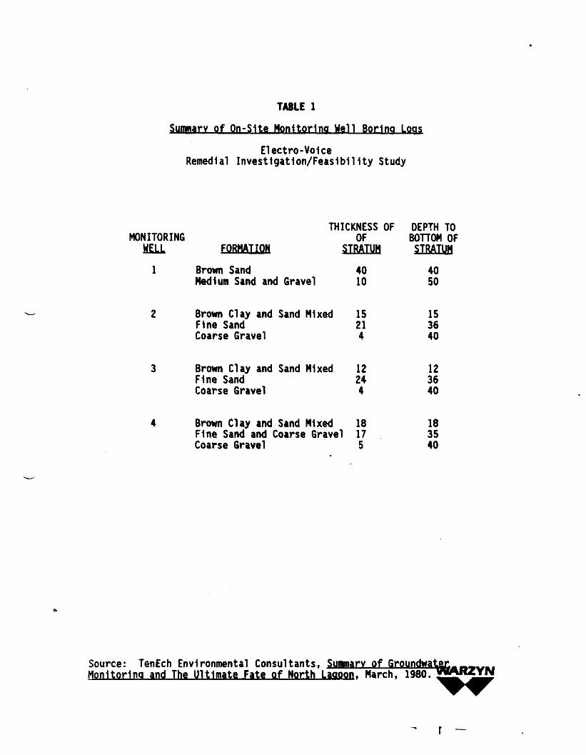
TABLE 1
Summary of Qn-Slte Monitoring Well Boring Loos
Electro-VoiceRemedial Investigation/Feasibility Study
THICKNESS OF DEPTH TOMONITORING OF BOTTOM OF
HELL FORMATION STRATUM STRATltfl
1 Brown Sand 40 40Medium Sand and Gravel 10 50
Brown Clay and Sand Mixed 15 15Fine Sand 21 36Coarse Gravel 4 40
Brown Clay and Sand Mixed 12 12Fine Sand 24 36Coarse Gravel 4 40
Brown Clay and Sand Mixed 18 18Fine Sand and Coarse Gravel 17 35Coarse Gravel 5 40
Source:Monitoring
TenEch Environmental Consultants, Summary of Groundwatara and The Ultimate Fate of North Lagoon. March. 1980. »«ARZYN

TABLE 2
Top of Casino and Static Water Level Elevationsfor
Qn-Slte Monitoring Wells
Electro-VoiceRemedial Investigation/Feasibility Study
Well Number
1
2
3
4
Top of CasingElevationfft MSL)
728.39
721.57
720.05
718.03
Depth toStatic Water
ifli40.83
34.58
33.08
33.25
Static WaterElevationfft MSL)
687.56
686.99
686.97
684.78
Notes:
1. Reference: 100.00 - 740.00 USGS (base of water tank)2. Data based on top of casing survey of January 11, 1980 and static water
level measurements of January 4, 1980.
Source: TenEch Environmental Consultants, Summary of Groundwater Monitoring andThe Ultimate Fate of North Laooon. March, 1980.
WARZYN
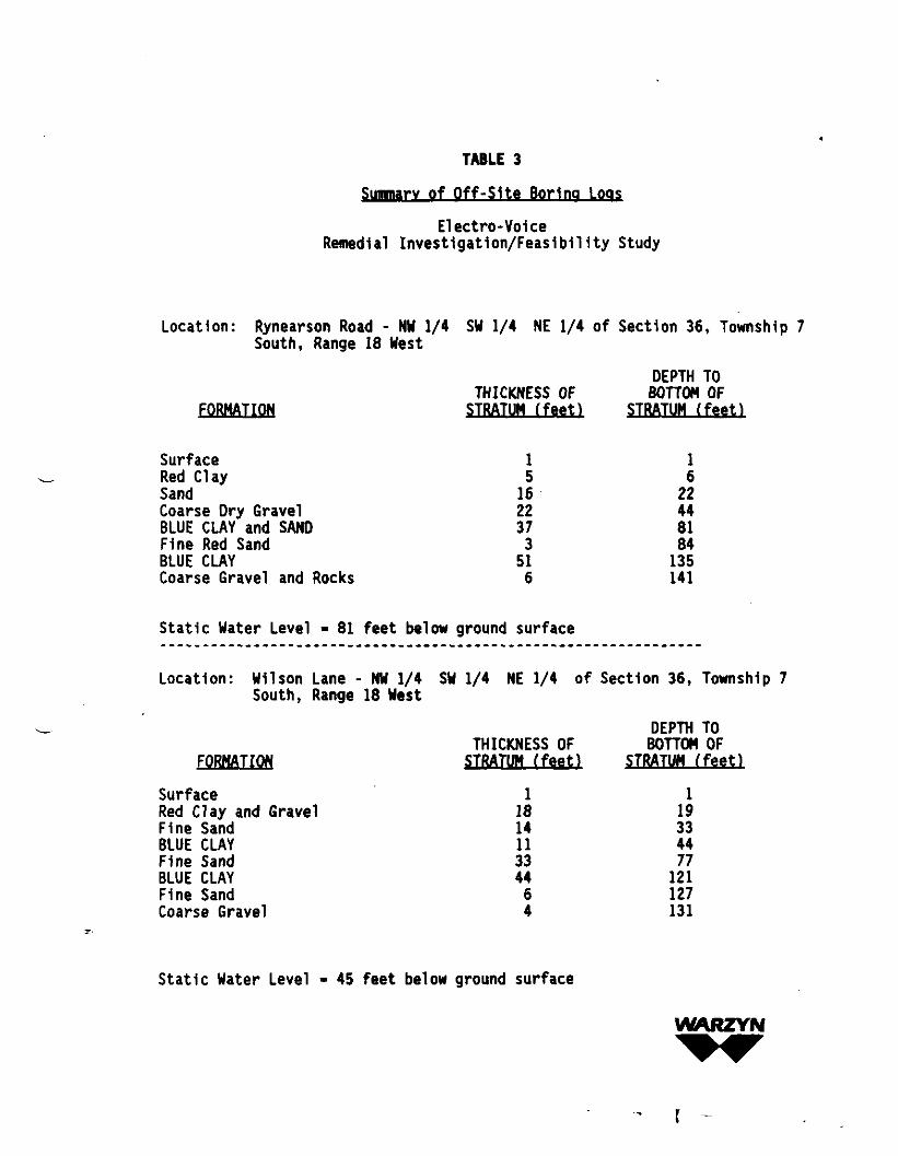
TABLE 3
Summary of Off-Site Boring Loos
Electro-VoiceRemedial Investigation/Feasibility Study
Location: Rynearson Road - NU 1/4 SW 1/4 NE 1/4 of Section 36, Township 7South, Range 18 West
DEPTH TOTHICKNESS OF BOTTOM OF
FORMATION STRATUM (feet) STRATUM ffeetl
Surface 1 1R e d Clay 5 6Sand 16 22Coarse Dry Gravel 22 44BLUE CLAY and SAND 37 81Fine Red Sand 3 84BLUE CLAY 51 135Coarse Gravel and Rocks 6 141
Static Water Level • 81 feet below ground surface
Location: Wilson Lane - NW 1/4 SW 1/4 NE 1/4 of Section 36, Township 7South, Range 18 West
DEPTH TOTHICKNESS OF BOTTOM OF
FORMATION STRATUM (feet) STRATUM (feet)
Surface 1 1Red Clay and Gravel 18 19Fine Sand 14 33BLUE CLAY 11 44Fine Sand 33 77BLUE CLAY 44 121Fine Sand 6 127Coarse Gravel 4 131
Static Water Level - 45 feet below ground surface
WARZYN
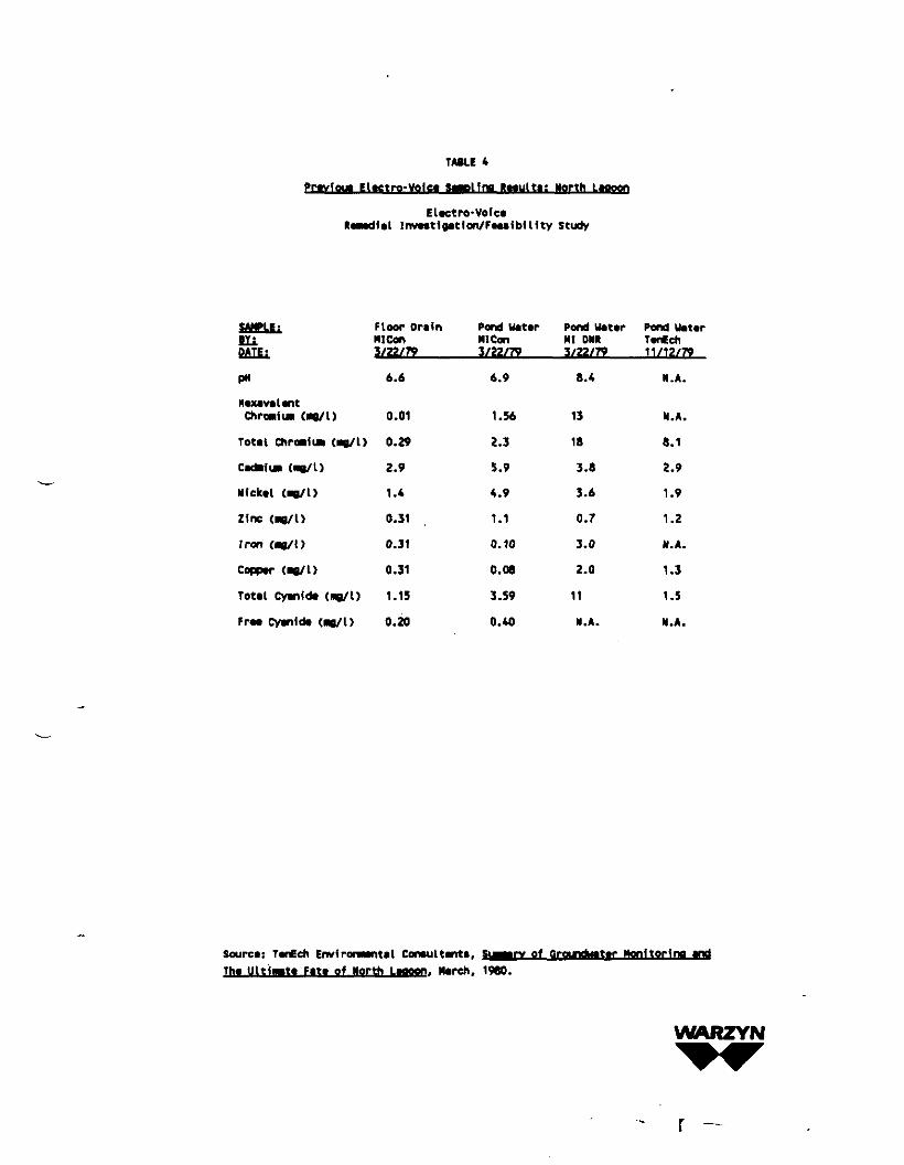
TABLE 4Pcavioua Elactro-VQiea SaacHna laautti: North Laooon
Elect ro- VoiceRemedial Inveatlgation/FeaaibUity Study
SdHELEifillDATE:
P«
HexavalantChroaiui («e/L)
Tout ChrtMluM (BO/I)
Cattail* («8/l)
Nfekal (as/I)
Zinc (ne/l)
Iron (mo/1)
Copper (ne/ I)
Total Cyanidt (ne/l)
Fra* Cyanide (M0/1)
Floor DrainMI Con3/22/79
6.6
0.01
0.29
2.9
1.4
0.31
0.31
0.31
1.15
0.20
Pond UatarMI Con3/22/79
6.9
1.56
2.3
5.9
4.9
1.1
0.10
0.08
3.59
0.40
Pond UatarHI ON*3/22/79
8.4
13
18
3.8
3.6
0.7
3.0
2.0
11
M.A.
Pond UatarTanCeh11/12/79
N.A.
N.A.
8.1
2.9
1.9
1.2
N.A.
1.3
1.5
M.A.
Sourca: TanEch Environmental Coneuitente,Tha UltiMta Fata of North Laaoon. March. 1960.
•tar Monitorina and
WARZYN
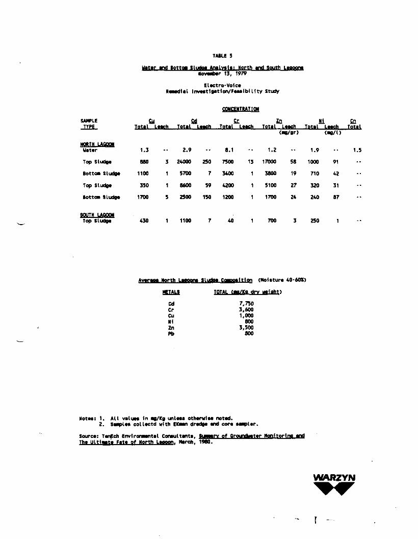
TABLE 5
Uatar and Bottoa Sludaa Analvala: North and South LaooonaNovwtwr 13, 1979
El*ctro-Voic*InvMtlutfon/FMsibflfty Study
CONCENTRATION
SAMPLETYPE
Uat*r
Top Sludg*
Bottom Sludg*
Top Sludg*
Bottom SLudg*
SOUTH LAOOOHTop Sludg*
£Total
1.3
880
1100
350
1700
430
ULMch
3
1
1
5
1
fidTotal Laaeh
2.9
24000
5700
8600
2500
1100
250
7
59
150
7
5XTotal L*ach
8.1
7500
3400
4200
1200
40
13
1
1
1
1
inTotal Laadi
1.2
17000
3800
5100
1700
700
(MQ/gr)
58
19
27
24
3
MiTotal
1.9
1000
710
320
240
250
Laach("0/0
91
42
31
87
1
CDTotal
1.5
-•
--
--
•-
--
Av*raoa Horth Laooon
METALS
CdCrCuNiZnPb
i Sludo* CgiHtfftltlon
TOTAL Cmo/Ka di
7,7503,6001.000
6003,500
800
Ttlon (Moittur* 40-60X)
Motw: 1. All valuM In no/Kg unl«M othcrwiM noted.2. SMplM colltctd with EKMn drvdg* and cor* Mapl*r.
Sourct: TcnEch Envfrocwantal Comultants, Suamry of Qround^atar Monitorfna andTh* Uitlaat* Fit* of North Laaoon. Ncreh, 1980.
WARZYN
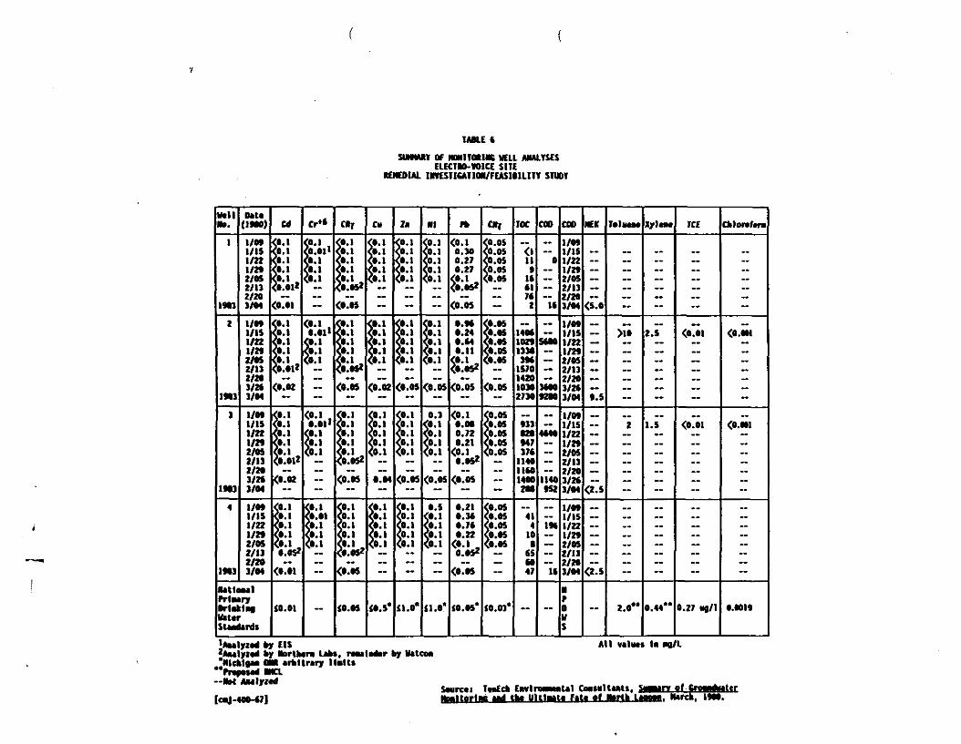
TABLE «
SUMNMV OF NOHITM1NC WELL ANALYSESELECTRO-VOICE SITE
REMEDIAL INVESTIGATION/FEASIBILITY STUDY
MilNa.
1
1903
I
1*3
3
1M1
4
Itt3
D*U0*M)
1/M1/151/221/292/OS2/112/201/04
1/MI/IS1/221/MZ/OS2/132/203/Z*3/04
1/MI/IS1/22l/»2/052/132/203/2f3/04
1/MI/IS1/221/2*Z/OS2/132/203/04
lUtlMUlMMryDrinkingtteUrSlMdirds
Cd
<p.ift!*.I&»»<O.OI
Isli,*<0.02
<0.1
CO.I(0.01*
<l.02
<0.1<0.l
<0.1<«.!,O.OS2
<0.01
$0.01
cr*<OJ i4*-1S.i<0.1
~<••' .
ft!—
<o.i ,
I..
<0.l(0.01
<0.l<•.!
~
—
«T
0.
0.».::«>
<0.05
<!*-<••CO.
^o.osz<0.05
<0.
I'.tf<0.05
<••(0.
5°*?o!o52
<0.05
iO.OS
CH
0
0B0
~
0.
1.0.
<0.02
9'
<$.0.04
<0.(0.
CO.<••
~
».s'
Zii
.
•
—
9'00.
^ '
<o.os
5°*
<o.
<0.05
<••at.
<ft-<o.
«
iiV
Nl
0
BB0
—
(0.
<•'>*•QO.
<0.05
0.1
<o.i
<O.OS
0.5<0.1
<0.1<0.1
—
«.o'
n><o.iO.Z70.27£•' *<O.OS2
<0.05
o.otO.M0.11
fri*<o.os
<0.1
<o.i• iw2
<O.M
0.210.3«
0.22<«•! ,0.0*2
<O.OS
(0.05*
CNi
<o.os<0.05<o.os<0.05
.-
<0.05
<o.os<».os
<0.05
<O.OS
<0.05
~
<o.osC0.05
<0.05<O.OS
~
(O.OJ*
TOC
"<l11tUftl7*2
14M102*1330J*4
1S70142010302730
•33020•4717t
1140lltO1400208
414
100
65CO47
—
COD
0
»
S*OQ
3000
4*40
1140tS2
m
U
~
coo»/M1/151/22l/2»2/052/132/203/04
1/M1/151/22l/»2/OSZ/132/203/M3/04
1/M1/151/22l/»2/052/132/203/2*3/04
1/M1/151/221/292/052/132/2*3/04
NfDUs
NEK
<slo
•.5
<Ts
a*
~
T«l MM
—
>io
2
--
2.0"
XylaM
..
2.S
1.5
~
0.44"
TCE
__
<0.01
<0.01
—
0.27 «g/1
Chlanhra
-
<O.MI
<O.N1
~
O.MI9
.—.,_— by CIS2AMlyz* by Nortbtm L*bi.
^NIcblOM OM Mtltrtry "~rrapOMfl RNCL
-Nat AMlyicd
by tetconAll VAlMts In «d/L
SourcttHiMltorliM
EwtroMNiiUl ComnltMti,MU Fit« of Norii . lurch. i*00.

TABLE 7
Proposed Phase 1 Well Locations and Rationale
Electro-VoiceRemedial Investigation/Feasibility Study
WELLNUMBER RATIONALE
MW 1-S To provide background water quality data on the southeastsection of the Electro-Voice facility.
MW 2-S To provide background water quality data on the northeastsection of the Electro-Voice facility.
MW 3-S To characterize general water quality and groundwater flow atthe northwest extent of the Electro-Voice facility.
MW 4-S To characterize groundwater flow and groundwater qualitydowngradlent of the electro-Voice facility and Electro-Voicefill area.
MW 5-S To characterize groundwater flow and groundwater qualitydowngradlent of hte Electro-Voice facility and just north ofthe previous lagoons.
MW 6-S To characterize groundwater flow and groundwter qualitydowngradlent of the Electro-Voice facility and immediatelywest of the previous lagoons.
MW 7-S To characterize groundwater quality and groundwater flowupgradlent of the lagoon area and downgradlent of the oldcity dump/gravel operation.
MW 8-D To characterize groundwater quality at depth and enablemeasurement of vertical gradient.
WArtZYN
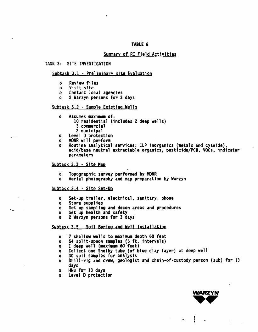
TABLE 8
Summary of RI Field Activities
TASK 3: SITE INVESTIGATION
Subtask 3.1 - Preliminary Site Evaluation
o Review fileso Visit siteo Contact local agencieso 2 Warzyn persons for 3 days
Subtask 3.2 - Sample Existing Wells
o Assumes maximum of:10 residential (Includes 2 deep wells)3 commercial2 municipal
o Level D protectiono MDNR will performo Routine analytical services: CLP Inorganics (metals and cyanide),
add/base neutral extractable organ!cs, pestlclde/PCB, VOCs, indicatorparameters
Subtask 3.3 - Site Mao
o Topographic survey performed by MDNRo Aerial photography and map preparation by Warzyn
Subtask 3.4 - Site Set-Up
o Set-up trailer, electrical, sanitary, phoneo Store supplieso Set up sampling and decon areas and procedureso Set up health and safetyo 2 Warzyn persons for 3 days
Subtask 3.5 - Soil Boring and Well Installation
o 7 shallow wells to maximum depth 60 feeto 54 split-spoon samples (5 ft. Intervals)o 1 deep well (maximum 60 feet)o Collect one Shelby tube (of blue clay layer) at deep wello 30 soil samples for analysiso Dr1ll-r1g and crew, geologist and chaln-of-custody person (sub) for 13
dayso HNu for 13 dayso Level D protection
WARZYN

TABLE 8
Summary of RI Field Activities(continued)
Subtask 3.6 - Groundwater Sampling and Aquifer Testing
o Sample 8 monitoring, 10 residential, 3 commercial and 3 municipalwells (24)
o 2 Warzyn personnel for 2 dayso 1 subcontractor person for 2 dayso Hydraulic Conductivity Testing will require 2 Warzyn personnel for 2
dayso Level 0 protectiono HNu for 4 days
Subtask 3.7 - Water Level Measurement
o MDNR will perform field work, Warzyn will Interpret datao 1 Uarzyn person for 1 day (office)
Subtask 3.8 - Elevation and Location Survey
o MDNR will perform
WARZYN
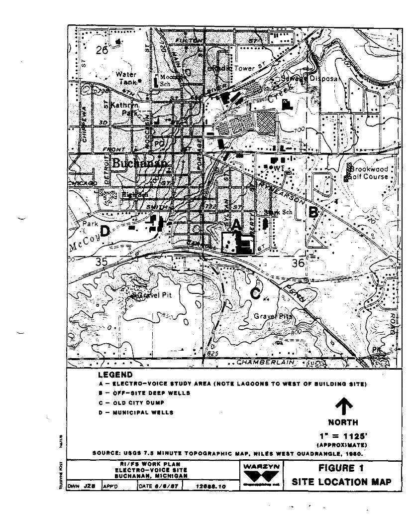
•-U , !' ••» >v
) I • 26*- S
^•v':
LEGENDA - ELECTRO-VOICE STUDY AREA (NOTE LAGOONS TO WEST OP BUILDING SITE)B - OFF-SITE DEEP WELLS
C - OLD CITY DUMP
D - MUNICIPAL WILLS
NORTH1" = 1125'
(APPROXIMATE)SOURCE: USQS 7.5 MINUTE TOPOGRAPHIC MAP. MILES WEST QUADRANGLE, 19SO.
OWN JZB
RI/PS WORK PLANELECTRO-VOICE SITEBUCHANAN, MICHIGAN
APP'O DATE 6/e/87 126*8.10
WAMZYN FIGURE 1SITE LOCATION MAP
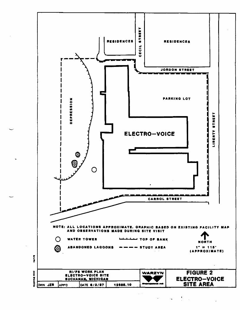
ELECTRO-VOICE
NOTE: ALL LOCATIONS APPROXIMATE. GRAPHIC BASED ON EXISTING FACILITY MAPAND OBSERVATIONS MADE DURING SITE VISIT
O WATER TOWER TOP OF BANK
ABANDONED LAGOONS — — — - STUDY AREANORTH
1" = 115*( A P P R O X I M A T E )
CWN JZB APP'O
RI/FS WORK PLANELECTRO-VOICE SITEBUCHANAN. MICHIGAN
DATE S/3/S7 12SSS.10
WARZYN FIGURE 2ELECTRO-VOICE
SITE AREA
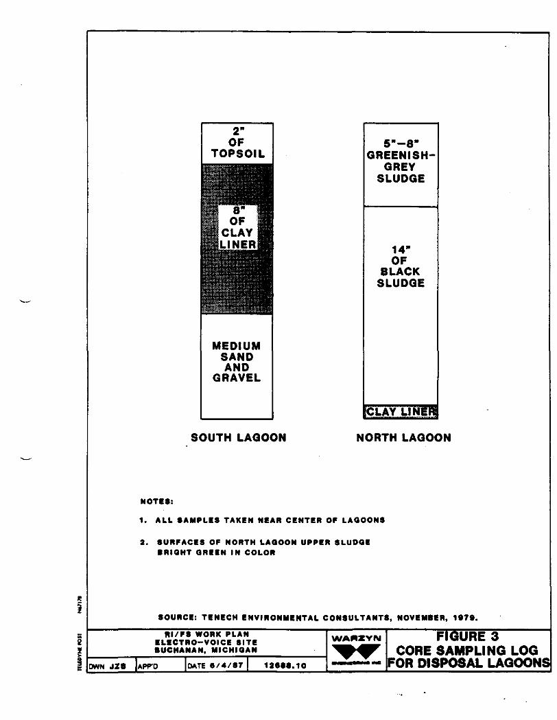
MEDIUMSANDAND
GRAVEL
GREENISHGREY
SLUDGE
14"OF
BLACKSLUDGE
CLAY LI NEK
SOUTH LAGOON NORTH LAGOON
NOTES:
1. ALL SAMPLES TAKEN NEAR CENTER OP LAGOONS
2. SURFACES OF NORTH LAOOON UPPER SLUDGEBRIGHT GREEN IN COLOR
SOURCE: TENECH ENVIRONMENTAL CONSULTANTS, NOVEMBER, 1079.
RI/FS WORK PLANELICTRO-VOICE SITEBUCHANAN, MICHIGAN
OWN JZB APPD DATE 6/4/87 12SSS.10
WAffZYN FIGURE 3CORE SAMPLING LOG
FOR DISPOSAL LAGOONS]

NORTH
(NOT TO SCALE)
SOURCE: MODIFIED AFTER TENCCH ENVIRONMENTAL CONSULTANTS,NOVEMBER. 1979.
FIGURE 4Rt/FS WORK PLAN
• LBCTRO-VOICt SIT!BUCHANAN, MICHIGAN
OWN JZB APPO DATE •/•/•? 12669.10
WAMZYN PRIOR DISPOSAL LAGOON!AND LOCATIONS
OF EXISTINGMONITORING WELLS
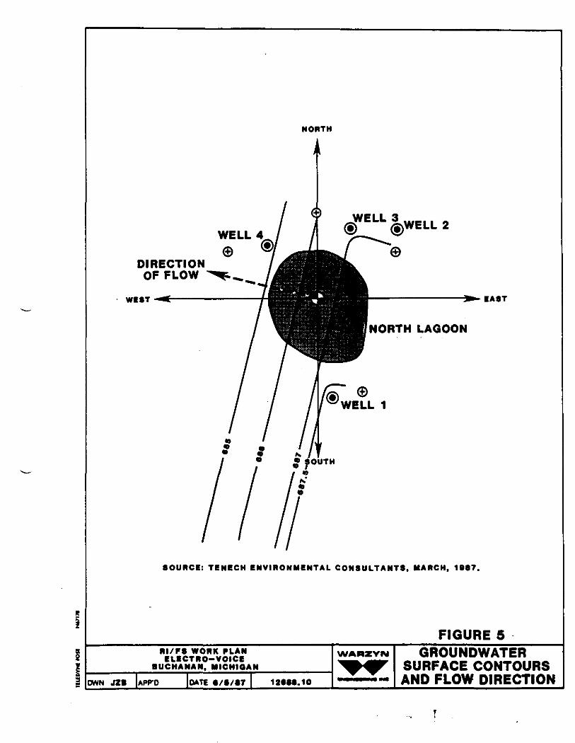
NORTH
DIRECTIONOF FLOW
WEST
WELL 2
NORTH LAGOON
EAST
SOURCE: TENECH ENVIRONMENTAL CONSULTANTS, MARCH, 198?.
FIGURE 5RI/FS WORK PLAN
CLICTRO-VOICEBUCHANAN, MICHIGAN
WAMZYIM
OWN JZB APP-D DATE e/6/ST 12SM.10
GROUNDWATERSURFACE CONTOURSAND FLOW DIRECTION
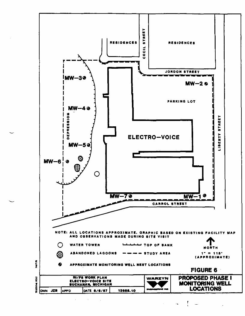
ELECTRO-VOICE
NOTE: ALL LOCATIONS APPROXIMATE. GRAPHIC BASED ON EXISTING FACIL ITY MAPAND O B S E R V A T I O N S MADE DURING SITE V IS IT
o WATER TOWER TOP OF BAN K
ABANDONED LAGOONS — — — — STUDY A R E A
APPROXIMATE MONITORING WELL NEST LOCATIONS
NORTH1" = 1 IS'
( A P P R O X I M A T E )
FIGURE 6HI/PS WORK PLAN
ELECTRO-VOICE SITEBUCHANAM, MICHIGAN
OWN JZB APFO DATE 9/S/87 12SSB.10
WAMZYN PROPOSED PHASE IMONITORING WELL
LOCATIONS

SLIP-ON WELL CAP PROTECTOR CASING WITH SLIP-ONTOP LOCKED AT TWO POINTS
GROUND SURFACE
GRANULAR BENTONITE(2 FT. MINIMUM)
2 IN. GALVANIZED WELL CASING
BENTONITE SLURRY
1O FT. STAINLESS STEEL RISER(2 INCH |.D.)
2 FT. BENTONITE PELLETS MINIMUM
2 FT. MINIMUM
10 FT. STAINLESS STEEL SCREEN(2 INCH I.D.)
COLLAPSED FORMATIONAND *30 FLINT SAND
WELL CONSTRUCTION DETAILNOT TO SCALE
RI/FS WORK PLANELECTRO-VOICE SITEBUCHANAN, MICHIGAN
OWN JZB DATE9/4/B7 12688.10
WAAZVN FIGURE 7TYPICAL WELL
CONSTRUCTION
r
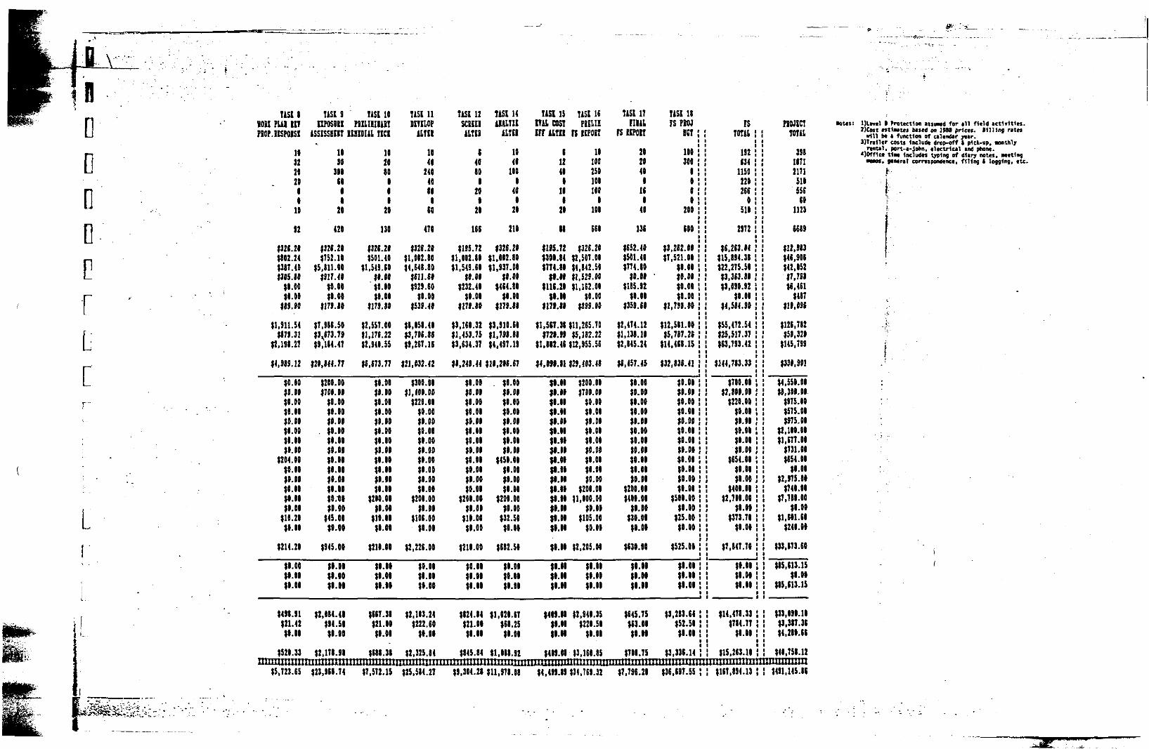
LC
L
* > -
usiiion FUI inFIOP.KSPOISl
1*322fl2088
10
92
$326.28$882.24$387.40$385.88
JO. 00$8.08
$89.90
$1,511.54$879.31
$2.138.27
$4.989.12
$0.00$0.00$8.00$8.00$0.00$9.00$8.00$0.00
$204.08$0.00$0.00$8.88$1.00$8.08
$19.20$0.00
$214.20
$8.00$1.00$8.68
$498.91$21.42
$0.06
$526.33nini t itt tnT
71SI9OPOSDKI
iSSKSHIT
1630
3086618
26
426
$326.20$752. »
$5.811.60$917.40
$0.00$6.60
$179.10
$7.986.50$3^673.79$9,184.47
$26,844.77
$200.00$706.00
$0.60$0.08$6.00
. $0.60$6.00$8.60$0.06$6.00$0.66$8.00$0.18$8.00
$45.60$0.00
$945.06
(0.00$9.00$8.61
$2,684.41$94.50$6.60
$2,178.91rrnnnnn
liSl 16PilLIIlIilT
KHDUl IICI
162080196
20
136
$326.26$$01.46
$1.549.60$6.66$0.00$6.08
$179.80
$2.557.60$l,17t.22$2,946.55
$6,673.77
$0.06$8.00$0.06$6.00$9.00$0.00$6.00$0.06$6.60$8.06$6.80$8.00
$280.06$8.00
$10.06$6.60
$216.80
$0.66$8.08$6.66
$6fi7.38$21.00$8.08
tSII 31miiimmni
TISl 11DimopUTII
1640
24040806
68
476
$326.20$1,062.86$4,648.80
$611.68$929.60
$0.06$539.40
$8,058.40$3,706.86$9,267.16
$21,032.42
$300.00$1,406.00
$229.00$0.00$8.00$0.00$6.00$9.00$0.06$8.00$0.00$8.69
$200.00$6.00
$106.00$0.00
$2,226.06
$0.06$6.60$0.09
$2,163.24$222.60
$9.96
$2,325.64rmJTTTmTTr
T1SI 12scanftlTII
64600
8206
26
166
$195.72$1,002.86$1,549.60
$6.08$232.40
$0.00$179.80
$3,168.32$1,453.75$3,634.37
$8,248.44
$6.06$8.06$0.00$8.00$0.00$6.06$0.00$0.06$8.89$9.00$8.00$0.00
$290.06$0.00
$16.08$0.00
$218.60
$8.69$9.99$6.69
$824.84$21.86$8.09
$845.84nimiiinr
TASK 14UAL-m
UN!
1946
1006
488
26
216
$326.20$1,002.80$1.937.00
$8.00$464.86
$6.00$179.89
$3,910.66$1,798.88$4,497.19
$16,206.67
. $0.00$0.00$8.00$0.06$6.00$8.00$0.86$6.66
$450.66$8.00$0.06$8.00
$209.00$0.00
$32.56$6.00
$682.$9
$6.00$0.66$6.86
$1,626.67$61.25$8.00
$1,088.92miinmm
US1151WCOSIIII iiTH
612469
168
26
18
$195.72$389.84$774.88
91.86$116.21
99.66$179.86
$1,517.38$729.99
$1,812.46
$4,999.81
19.6699.6991.99$9.6899.86$9.99$9.99J9.1699.6999.9999.66$6.8999.98$9.9999.9996.68
$6.68
$8.68$11196.99
8499.9199.6898.69
$469.68Mimiiiiii
USI 16PEELII
n KPOII
16100256100100
0100
6GO
$326.20$2,507.00$4,842.50$1,529.00$1,162.00
$0.00$899.00
$11,265.70$5,182.22
$12,955.56
$29,403.48
$200.00$700.00
$0.08$0.00$0.00$0.00$0.00$0.00$0.00$6.06$0.00
$200.0011,000.00
$0.00$105.00
$0.00
$2,205.08
$6.09$0.00$6.06
$2.940.35$229.56
$8.06
13,166.85imiYTTYTTT
TiSl 17niursupoir
2620469
166
40
13S
$652.40$501.46$774.80
$0.66JIB5.92
$6.66$359.60
$2,474.12$1.131.16$2,145.24
$1,457.45
$6.60$0.00$6.06$0.00$0.08$0.00$0.06$6.60$0.06$6.60$0.08
$208.66$406.99
$9.60$39.90$9.06
$639.96
$9.99$9.09$9.99
$645.75$13.01$9.99
$766.75miiiiinim
$5,723.65 '~$23,96i~74 $7.572.1$ $25,584.27" $9,304.28~$11,S78.D8 $4.499.89 $34.7^32 $7.796.29
TiSl 18?S PEW FS Rum
167
166300
8099
200
600
$3,212.00$7,521.06
$8.60$0.00$0.00$0.00
$1,798.00
$12,511.00$5,787.26
$14,411.1$
$32,831.41
$0.98$8.60$0.00$0.60$6.00$0.69$9.00$0.06$0.00$0.06$0.00$9.08
$508.00$0.00
$25.00$0.00
$$25.00
$6.09$9.06$8.09
$3,283.64$52.56$6.89
$3,331.14im***t*i»*»H
$36,697.55
70TAI
192634
1150220266
0516
2972
$6.263.04$15,894.38$22.275.50$3,363.86$3,690.92
$8.00$4,584.90
$55,472.54$25,517.37$13,793.42
$144,703.33
$700.00$2,806.00
$220.00$0.00$0.96$9.00$6.00$0.00
$654.09$0.66$6.00
$400.60$2,700.00
$6.00$373.78
$6.09
$7,847.76
$9.66$6.09$9.66
$14,478.33$784.77
$8.66
$15,263.16HUttHHHtHt
$117,894.13
T0711
39811712171518556
601123
1189
$12,983$46,906$42,652$7,7S8$6,411
$487$18,091
$126,782$51.326
$145.799
$336,901
$4,550.00$1,300.00
$975.00$575.00$975.00
$2,190.00$1,177.00
$731.06$654.00
$9.09$2,975.09
$740.99$7,711.00
$6.00$1,101.68
$248.09
$33,873.66
$85,113.15$1.99
$85,113.15
$33,999.16$3.387.31$4.289.66
$48.758.12IHHtMtmtH
$491,145.81
* ..-Wiv
Mm: Dlncl 0 Protection atsived for ill field activities.2)Cost ntlMtes based on 1988 prices. Billing rites
will be • function of calendar year.3)Trailer costs lacludt drop-off t pick-up. Monthly
rental. port-a-John, electrical and phone.«)0ff1ce UM Includes typing of diary notes. Meeting
—--«. gmral correspondence, filing I logging, etc.
t .
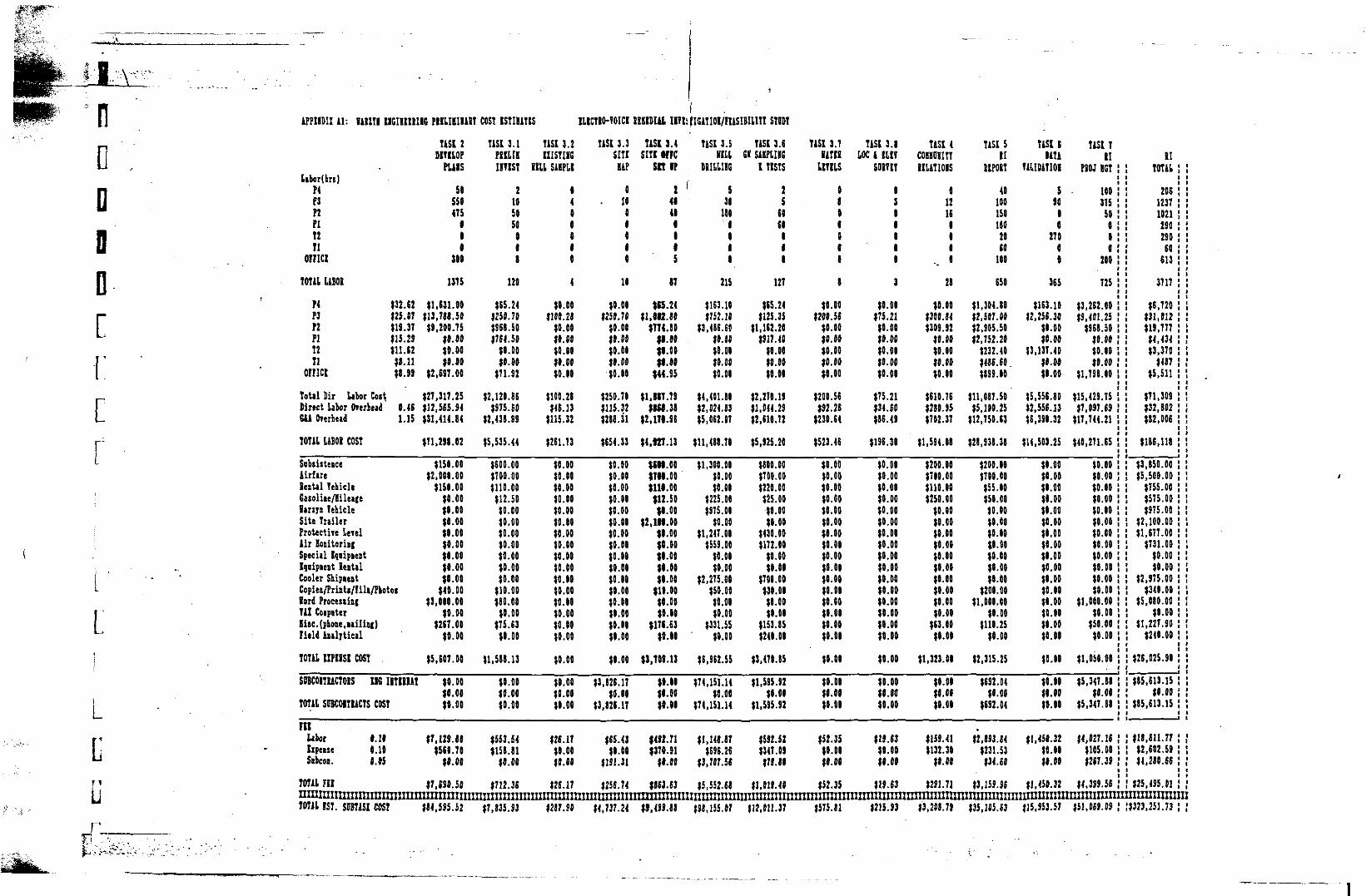
la
L
L
L
APPIIDII il: IlIZTI U6IHI1I1G PHUBIHIT COST ISTIH&TIS HKTI0-TOICI BEKIDIU ITIifKlTIOI/IUSIBUm STODT
LJ
TASI 2DimopPUIS
labor (hrs)P4 58P3 550P2 4T5PI aT2 111 0
ornci sotTOm UBOI 1375
P4 132.62 $1,631.00P3 $25.07 $13,788.50P2 $19.37 (9,200.75PI US. 29 $9.00T2 til. 6! ?0.00Tl 18.11 $0.00
OrnCt $8.99 $2,697.00
Total Dir labor Cos\ $27,317.25Direct Labor forbad 0.46 $12,565.84GU Onrbead 1.15 $31,414.84
70T1L UBDi COST $71,298.02
Subsistence $150.00Airfare $2,000.00Seatal Yekicle $150.00Gasoline/Hi leage $0.00lanjn TeMcle $0.00Site Trailer $0.00Protect lie Leiel $0.00iir Hoaitorinj $0.00Special Iqnipient $0.00Iqoipient lentil $0.00Cooler Sbipiest $0.00Copies/PrinU/lili/Pbotoi $40.00lord Procesti&f $3,000.00741 CoipQter $0.00liac. (phone, lailiai) $267.00Field Analytical $0.00
TOTAL nPIISI COST $5,607.00
SOKOITUCT01S I1G IITIEUT $0.00$0.00
TOTAL SUBCOITIACTS COST $0.00
FIILabor 0.10 $7,129.80Ixpense 0.10 $560.70Snbcon. 0.05 $0.00
TOmiH $7,690.50
T1SI 3.1PBILIHIITIST
2105050008
120
$E5.24$250.70$968.50$764.50
$0.00$0.00
$71.92
$2,120.96$S75.EO
$2,438.99
$5,535.44
$600.00$TOO.t)0$110.00$12.50
$0.00$0.00$0.00$0.00$0.00$0.00$0.00
$10.00$60.00
$0.00$75.63
$0.00
$1,588.13
$0.00$0.00$0.00
$553.54$158.81
$0.00
$712.36
TASI 3.2IIISTIIG
BILL SiKPLI
14
4
$0.00$100.28
$0.00$0.00$0.00$0.00$0.00
$100.28$46.13
$115.32
$261.73
$0.00$0.00$0.00$0.00$0.00$0.00$0.00$0.00$0.00$0.00$0.00$0.00$0.00$0.00$0.00$0.00
$0.00
$0.00$0.00$0.00
$28.17$0.00$0.00
$26.17
TASI 3.3 TASI 3.4SITI 5ITI MFC
HAP SIT Of
0 2. 10 41
401115
10 87
$0.00 $55.21$250.70 $1,W.80
$0.00 $774.80$0.00 $1.00$0.00 $1.00$0.00 $1.00$0.00 $44.95
$250.70 $1,817.79$115.32 $8M.3S$288.31 (2,170.96
$654.33 $4,927.13
$0.00 $CH.OO$0.00 $710.00$0.00 $111.00$0.00 $12.50$0.00 $0.00$0.00 $2,111.00$0.00 $0.00$0.00 $1.00$0.00 $0.00$0.00 $0.00$0.00 $0.00$0.00 $10.00$0.00 $0.00$0.00 $0.00$0.00 $176.63$0.00 $0.00
$0.00 $1,709.13
$3,826.17 $1.00$0.00 $1.00
$3,026.17 $1.01
$65.43 $492.71$0.00 $370.91
$191.31 $1.00
$256.74 $863.63
TASI 3.5ULL
DB1UII5|! 5
30180
0001
215
$163.10$752.10
$3,486.60$0.00$0.00$0.00$0.00
$4,401.80$2,024.83$5,062.07
$11,488.70
$1,300.00$0.00$0.00
$225.00$915.00
$0.00$1,247.00
$559.00$0.00$0.00
$2,275.00$50.00$0.00$0.00
$331.55$0.00
$6,962.55
$74.151.14$0.00
$74,151.14
$1,148.87$696.26
$3,707.56
$5,552.68
TASI 3.6H SAHPLIIG
I TISTS
25
6060
000
127
$65.24$125.35
$1,162.20$917.40
$0.00$0.00$0.01
$2,270.19$1.044.29$2,610.72
$5,925.20
$800.00$700.00$220.00$25.00
$0.00$0.00
$430.00$172.00
$0.00$0.00
$708.00$30.00$8.00$0.00
$153.85$240.00
$3,470.85
$1,595.92$0.01
$1,595.92
$592.52$347.0S$79.89
$1.019.40
TASI 3.71ATK
LITIIS
0
8
$0.00$200.56
$0.00$0.00$0.00$0.00$0.00
$200.56$92.26
$230.64
$523.46
$0.00$0.00$0.00$0.00$0.00$0.00$0.00$0.00$0.00$0.00$0.00$0.00$0.00$0.00$0.00$0.00
$0.00
$0.00$1.00$0.00
$52.35$0.00$1.01
$52.35
TASI 3.8LOC A III?
sonn
3
$0.00$75.21
$0.00$0.00$0.00$0.00$0.00
$75.21$34.60$86.49
$196.30
$0.00$0.00$0.00$0.00$0.00$0.00$0.00$0.00$0.00$0.00$0.00$0.00$0.00$0.00$0.00$0.00
$0.00
$0.00$8.00$0.00
$19.63$0.00$0.00
$19.63
TASI 4 TASI 5COBHOHITT 111IUTIOIS UPOGT
0 4012 10016 1501 1801 201 60
., i mo28 650
$0.00 $1,304.80$300.84 $2,507.00$309.92 $2,905.50
$0.00 $2,752.20$0.00 $232.40$0.00 $486.60$0.00 $899.00
$610.76 $11,087.50$280.95 $5,100.25$702.37 $12,750.63
$1,594.08 $28,938.38
$200.00 $200.06$700.00 $700.00$110.00 $55.00$250.00 $50.00
$0.00 $0.00$0.00 $0.00$0.00 $0.00$0.00 $0.00$0.00 $0.00$0.00 $0.00$0.00 $9.00$0.00 $200.00$0.00 $1,000.00$0.00 $0.00
$63.00 $110.25$0.09 $0.00
$1,323.09 $2,315.25
$0.09 $(92.04$9.00 $0.00$0.00 $692.04
.$159.41 $2,893.84$132.30 $231.53
$0.00 $34.60
$291.71 $3,159.96
IASI 6 TASt 7DATA II 11
miDAlIOl PIOJ RGT
5 . 10030 3751 501 1
270 01 01 200
365 725
$163.10 $3,262.00$2,256.30 $9,401.25
$0.00 $968.50$0.00 $0.00
{3,137.40 $0.00$0.00 $0.00$0.00 $1,798.00
$5,556.80 $15.429.75$2,556.13 $7,097.69$6,390.32 $17,744.21
$14,503.25 $40,271.65
$0.00 $0.00$0.00 $0.00$0.00 $0.00$0.00 $0.00$0.00 $0.00$0.00 $0.00$0.00 $0.00$9.00 $0.00$0.00 $0.00$0.00 $0.00$0.00 $0.00$0.00 $0.00$0.00 $1,000.00$0.00 $0.00$1.00 $50.00$0.00 $0.00
$0.00 $1,050.00
$9.00 $5,347.88$1.00 $0.00$0.00 $5,347.88
$1,450.32 $4,027.16$0.09 $105.00$0.00 $267.39
$1,450.32 $4,399.56nmnnnnnnxmnixniinxximi^^TOTAL 1ST. SDBTASI COST $84,595.52 $7,835.93 $287.90 $4,737.24 $9,499.88 $98,155.07 $12,011.37 $575.81 $215.93 $3,208.79 $35,105.63 $15,953.57 $51,069.09
I
TOTAL
206123710212SO29060
613
3717
$6,720$31,012$19,777$4,434$3,370
$487$5,511
$71,309$32,802$82,006
$186,118
$3,850.00$5,500.00
$755.00$575.00$975.00
$2,100.00$1,677.00
$731.00$0.00$0.00
$2,975.00$340.00
$5,080.00$0.00
$1,227.90$240.00
$26,025.90
$85,613.15$9.00
$85,613.15
$18,611.77$2,602.59$4,280,66
$25,495,01tnirainni i$323,251.73

APPEHDII i-2 IIGIHHS IITIKUTIOUL PBELIHINABT COST ESTIHATESELECTHO-TOICE REHEDIAL imSTIGATION/FEASIBILITT ST0DT
TASI 3.3SITS
TISI 3.5NELL
TASK 3.6GH SAMPLING
TASK 5 TISK 7BI BI Bl
Labor(hrs)P4P3P2PIT2Tl
OFFICE
TOTAL LABOR
P4 $29.22P3 $21.22P2 $16.21PI $9.26T2 $10.25Tl $8.68
OFFICE $8.88
Total Dir Labor CostDirect Labor Overhead 0.35Gil Overhead 1.10
TOTAL LIBOB COST
Expense IteiTransportationSubsistenceProtection le?elSpecial equipieat
TOTAL EIPEKSS COST
SubcontractsAbrais Aerial PhotoETI
TOTIL SDBCOKTRACTOBS COST
feeLabor 0.12Expense 0.08Sdbcon. 0.05
TOTIL FES
TOTAL EST. S5BTASI COST
H
$146.$212.$162.$165.$o.$0.$0-
$705.$246.$776.
$1,728.
$0.$o.$0.$0.
$0.
$1,800.$0.
$1,800.
$207.$0-$90.
$297.
$3,826.
IP
5101020000
45
10201020000000
GO9616
72
00000000
00
000000
450000
45
17
DBILL
$0$0$0$0
$1,742$0$0
$1,742$609
$1,916
$4,269
$150$1,300$559$0
$2,009
$0$64,000$64,000
$512$160
$3,200
$3,873
$74,151
ING
0000
17000
170
.00
.00
.00
.00
.50
.00
.00
.50
.88
.75
.13
.00
.00
.00
.00
.00
.00
.00
.00
.30
.72
.00
.02
.14
& ITE
$0$0$0$0
$410$0$0
$410$143$451
$1,004
$150$200$86$0
$436
$0$0$0
$120$34$0
$155
$1,595
5TS
00004000
40
.00
.0000.00.00.00.00
.00
.50
.00
.50
.00
.00
.00
.00
.00
.00
.00
.00
.54
.86
.00
.42
.92
BEP
$146$106$0$0$0$0$0
$252$88$277
$617
$0$0$0$0
$0
$0$0$0
$74$0$0
$74
$692
)8T
5500000
10
.10
.10
.00
.00
.00
.00
.00
.20
.27
.42
.89
.00
.00
.00
.00
.00
.00
.00
.00
.15
.00
.00
.15
.04
PBOJ 1
$730$1,061
$0$0$0$0$0
$1,791$627
$1,970
$4,389
$200$200$0$0
$400
$0$0$0
$526$32$0
$558
$5,347
6T
255000000
75
50000000000000
50.03.65
.18
.00
.00
.00
.00
.00
.00
.00
.00
.70
.00
.00
.70
.88
TOTAL
3565102021000
340
$1,022.70$1,379.30$162.10$185.20
$2,152.50$0.00$0.00
$4,901.80$1,715.63$5,391.98
$12,009.41
$500.00$1,700.00$645.00$0.00
$2,845.00
$1,800.00$64,000.00$65,800.00
$1,441.13$227.60
$3,290.00
$4,958.73
$85,613.14

1PFIID1I B PEWICT SCIIDDLE
IOITES
IIECTEO-TOICI EEKEDUL IITISTIGlTIOI/rEiSIEIMII STDDI
1 ! 1 13 15
it :I!i :i ;i :r ;i:L ;ii!1sTIG1TI0E
!Ii5IBILITT
5TgDi
misT1SI 2-PUES AID BiJACmil
U-IOU PLAEM-WPP!.3-SAEFLIES PLAEI.MEALTE/SIFITT PLAI
TISI 3-S1TE IETISTIGATIOE
U-milB Slit ITAl3.1-EIISTIEG KILL SAEFUEG3.3-SITt BASE EiF3.4-SITI SIT-BP3.5-IEU IESTALLATIOE3.G-C1DIT1 SABPLIEG3.T-G!Dm LI1ELSi.i-ucmn SBITIT
TASE 4-COEEOHTT UUTI01S
TASI 5-EI iJPOBI
USI G-CATA ASSESS/TALIE1T10E
TASE T-II FICJECI EAEAGEEIH
USI 1-SUC11FTIOI 0! FIOF. EES.
USI 9-E1S1 ASSISSEEET
USE 1HEILII. EEE. T1CERDLOGTi1 TASE M-DimoP ALTZESATITIS
TA£i :MI:TIU scEninsTASI U-tEAE IOTIFICATIOI
! TISE H-ItlL. Of ALTEEIA!1T!Si! TAKE 15-tm. OF COST IFF. ALT.i1 TASE 1E-EIAFT FS EEPOETi! TASI 17-riEll FS HPOET
! TiSI ll-K HfiJtrT miirnriT
1 1 3 4 5 E T 1
..... 0j
9 It 11 12
B( .....
*"""""""****""
3 14 15 1G ! IT U 19 10
— — — — -i
.............. .... — — . —
1 21 2! 21
..... o,
......... — —
5 2( IT 21
6(
.... ————— —
9 10 31 31
..........0—-——0
..............
3 34 3S 3f
\\\\\\\\\\\\\\\
*"**"""""'""""
1 31 39 41
\\\\....(II
mm
""""""""*"
1 41 43 44
\\\\\\\\\V\\\\I\\\\\\In
..... i, i
- - - - - Is 1
...---......-.
4E 41 41
\\\\\\\\\\\\\\\\\\
X
kd - - - - -ti ...... ...»
•
SB 51 SI S4 SS 51 SI 51
- - - - ii
- - - - - Oi
...... ft
omci mi Illimil FIELD ACTITITIES \\\\\\\\\ LAB nUUOrjN Till UII HTIH 11 HIETISGS 0 «POB! AUKS
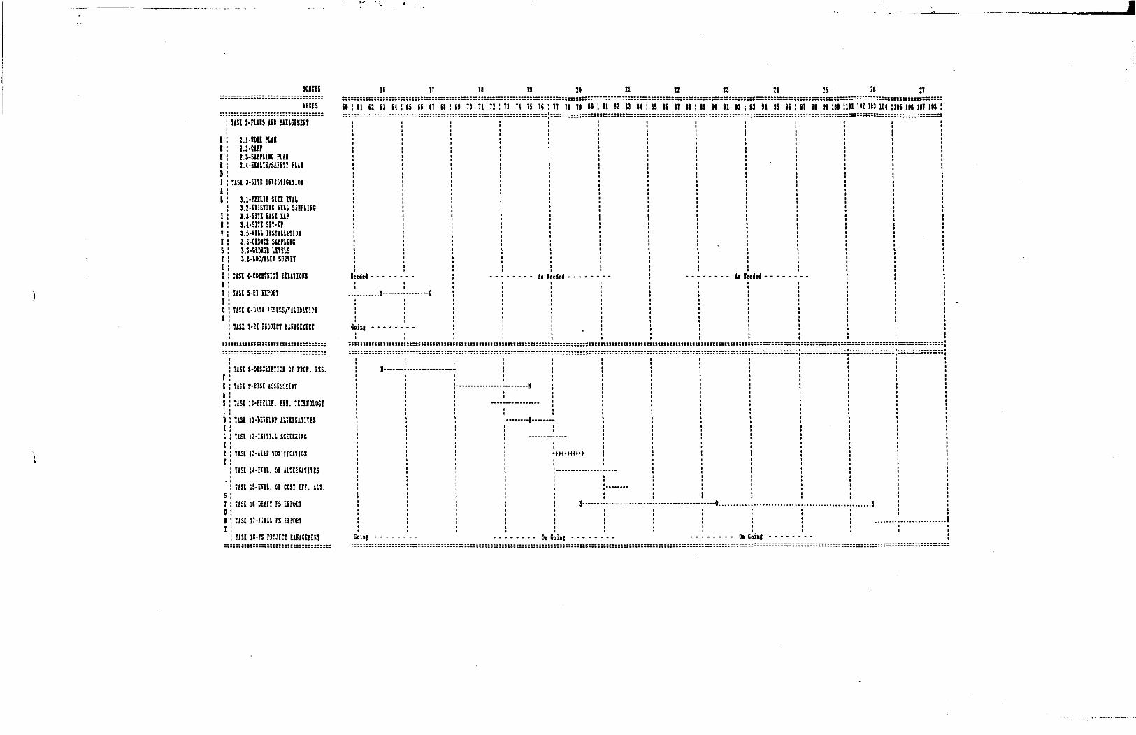
IOI7HS
REEES:isi 2-Fitis in
1.1-IOU FLU1.1-UPP2.3-SiEPLIIG Pill2.{-imiE/£lFET! Pill
USE 3-S1TE IITISTIGIIIOI
3.1-FEEU1 SITE EHl3.i-nisTiiG mi supine3.3-SITE EiSI EiFU-Sni SET-DP3.5-nil USULUTIOI3.E-GEHTI SilFLiSG3.7-GEDfTl IETEISi.e-lOC/ELEt SOETEI
USE {'COEEKITI EEL&TIORS
USE 5-11 HFCET
USE 6-EIU iSEEESAiUltTIOl
USE 7-EI rtO.'lCT EiEiGEEEET
!isE i-9Es;tiPT!oi or ptop. m.!i£t S-E1SE ISSESSUI7
USE !C-FiEllI. Ift. IECEBOLOST
TISl IH'ETEIOP ILIEESITHES
USE 12-IJ1T1
USE 13-1E1E
tiEE H-ETil. OF ilTEEKITITES
USE IS-EUI. OF CCS! EFF. ill.
USE IE-Elm FS EEPOEI
USE n-nm rs EI?CSTTIU ii-rs piwin uncnnT
ei
i
IE
i e: E3 E4
jej ......
I-—.
n * . * - .
!„..„
IT 11 19 » 21 22 23 24 tt 2G ]T
5 EG El El
...,..-0
.:::::::-:""
9 7fl 71 72 3 14 T5 TG
AD
-— —— H— —
T T) 71 H
ded - - - - -
•tmowt
1 R2 13 14 S 16 17 11 9 91 91 92
..... j, |
-—0.........
!..... oi
3 11 IS 36
del .....
T 91 S3 111 1 1D2 Id 104
.......!
5 IK 1IT Iftl


![2015 / 16...Southampton FC Stoke City FC Sunderland AFC Swansea City AFC Tottenham Hotspur FC [London ] Watford FC West Bromwich Albion FC West Ham United FC [London ] …](https://img.pdfslide.us/doc/110x75/6147d88ca830d0442101b33e/2015-16-southampton-fc-stoke-city-fc-sunderland-afc-swansea-city-afc-tottenham.jpg)