Embed Size (px)
DESCRIPTION
PDC bit design
Citation preview

7th- 8th November, 2013Karachi. Pakistan
Agenda
Morning Session Fixed Cutter Bit Fundamentals HDBS FC New Technologies Break Roller Cone Bits Fundamentals HDBS RC New Technologies Dull Grading FC & RC
Afternoon Session Drilling & Drill Bit Optimization Break Drilling Problems & Remedies Open Discussion
Closing

3
PDC(Shearing)
Impregnated &Natural Diamond
(Grinding)
Roller Cone(Crushing/Gouging)
General Cutting Mechanics PDC
– Shearing
Natural Diamond and Impregnated Drilling
– Grinding– Hard and abrasive applications– Inefficient for non-abrasive
formations
Rollercone– Crushing– Gouging
Fixed Cutter Bit Types
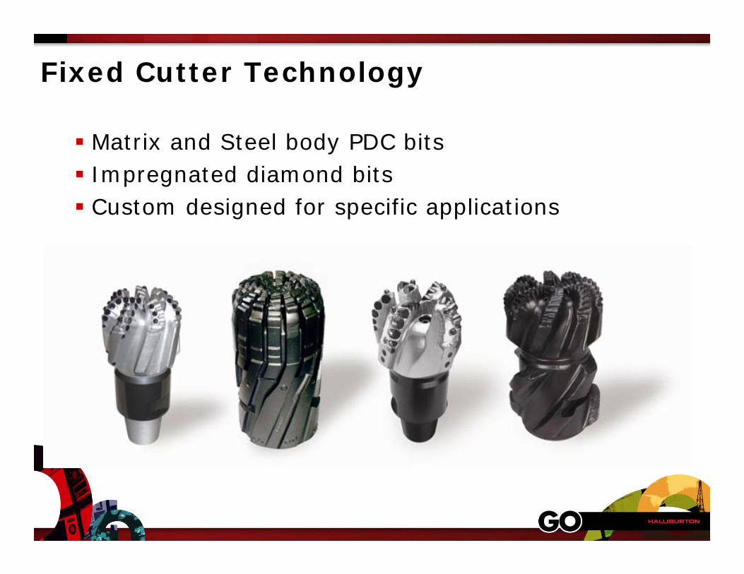
Fixed Cutter Technology
Matrix and Steel body PDC bits Impregnated diamond bits Custom designed for specific applications
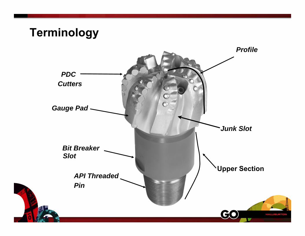
Terminology
PDC Cutters
Profile
Gauge Pad
Bit Breaker Slot
API Threaded Pin
Junk Slot
Upper Section

Fixed Cutter Bit Types
Matrix Body• Improved resistance to bit body wear and erosion
• More applicable to long hours or multiple runs
Steel Body• Increase cutting volume capacity for higher ROP applications
• Can be designed with much higher blade stand off
• Treatment applications to improve bit cleaning and reduce bit balling
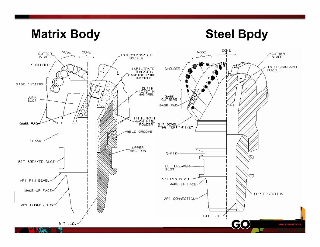
Matrix Body Steel Bpdy
Fixed Cutter Bit Fundamentals
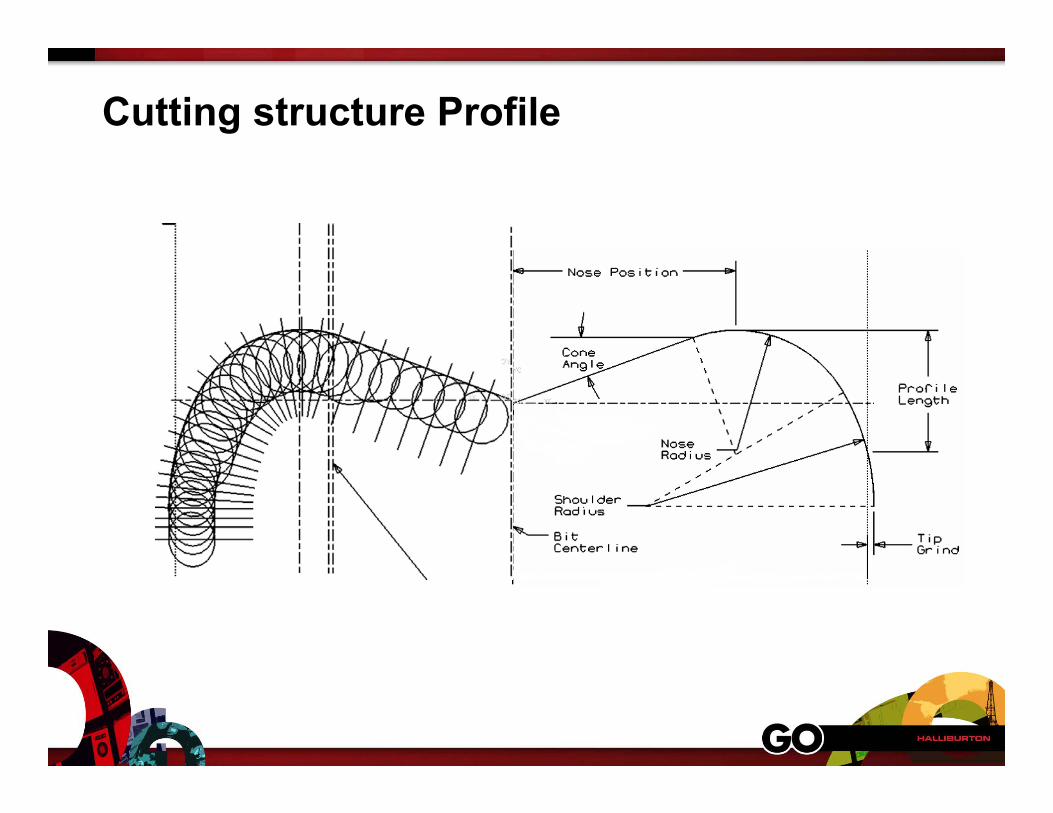
Cutting structure Profile
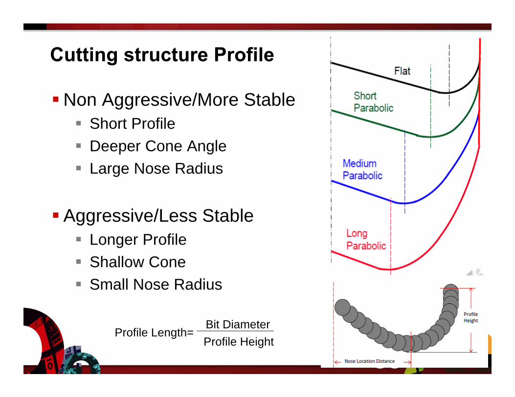
Cutting structure Profile
Non Aggressive/More Stable Short Profile Deeper Cone Angle Large Nose Radius
Aggressive/Less Stable Longer Profile Shallow Cone Small Nose Radius
Profile Length= Bit DiameterProfile Height
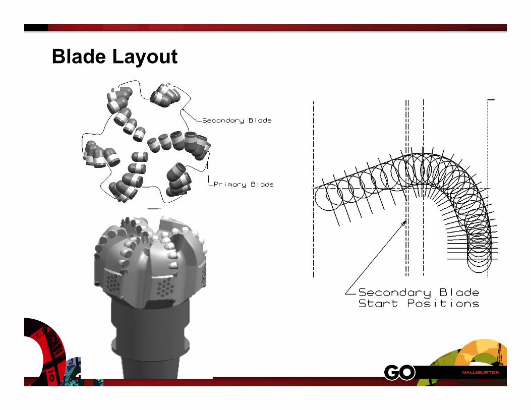
Blade Layout
Blade Layout
Higher Blade Count Less Aggressive More Stable Harder to Clean at High ROP Less Nozzles
Lower Blade Count More Aggressive – Higher ROP Less Stable Easier to Clean at High ROP More Nozzles
Blade Layout
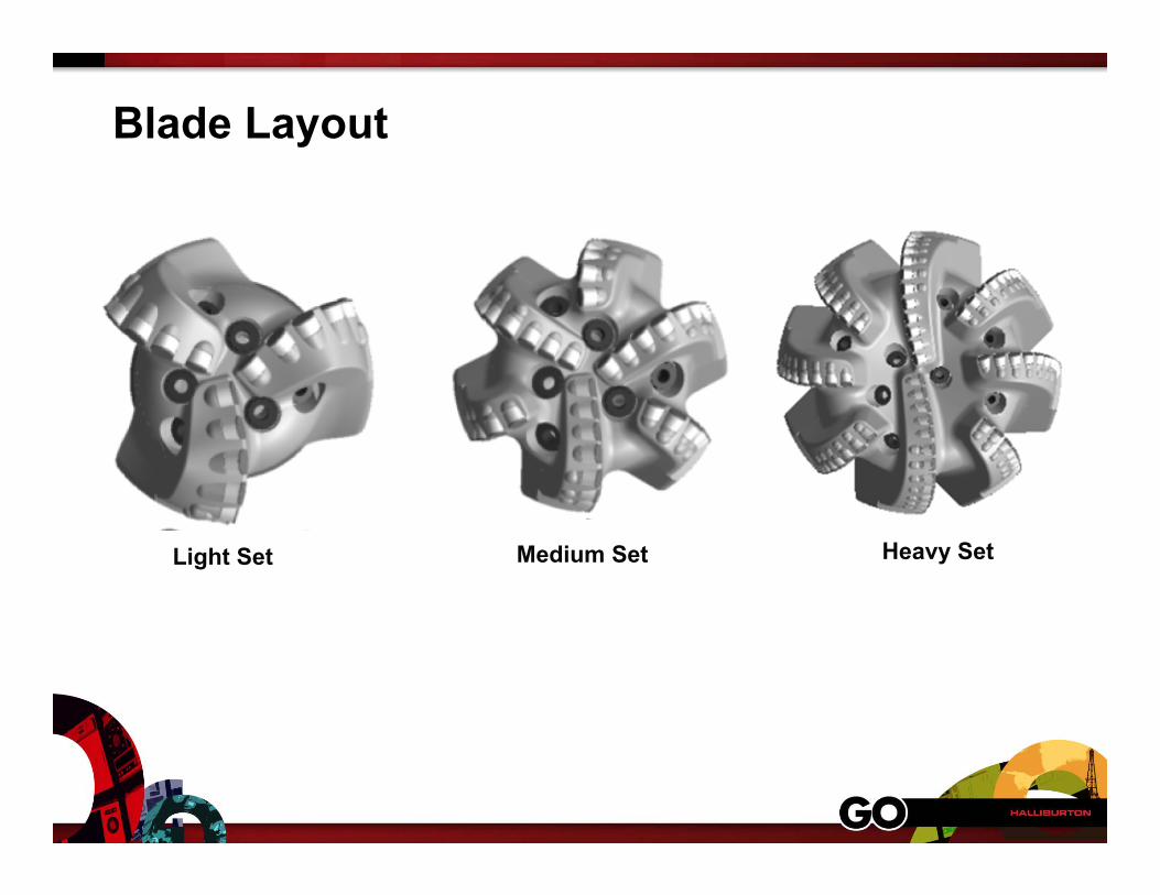
Light Set Heavy SetMedium Set
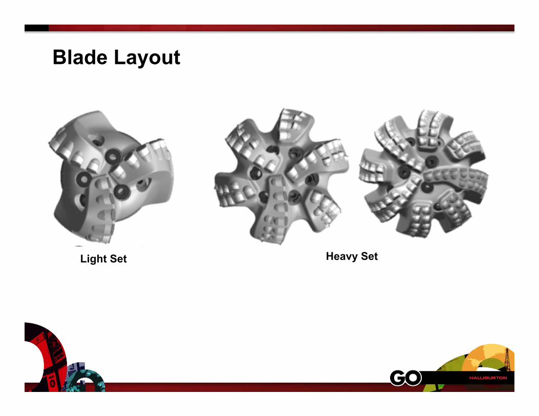
Blade Layout
Light Set Heavy Set
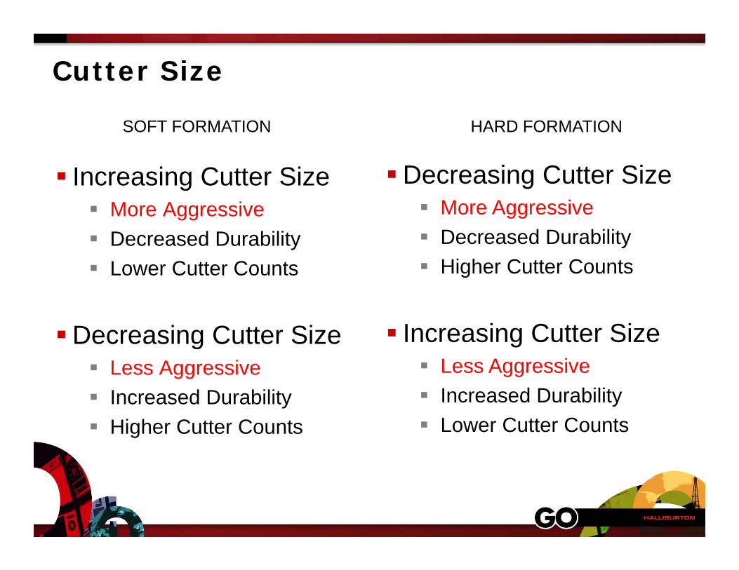
Cutter Size
Increasing Cutter Size More Aggressive Decreased Durability Lower Cutter Counts
Decreasing Cutter Size Less Aggressive Increased Durability Higher Cutter Counts
SOFT FORMATION
Decreasing Cutter Size More Aggressive Decreased Durability Higher Cutter Counts
Increasing Cutter Size Less Aggressive Increased Durability Lower Cutter Counts
HARD FORMATION
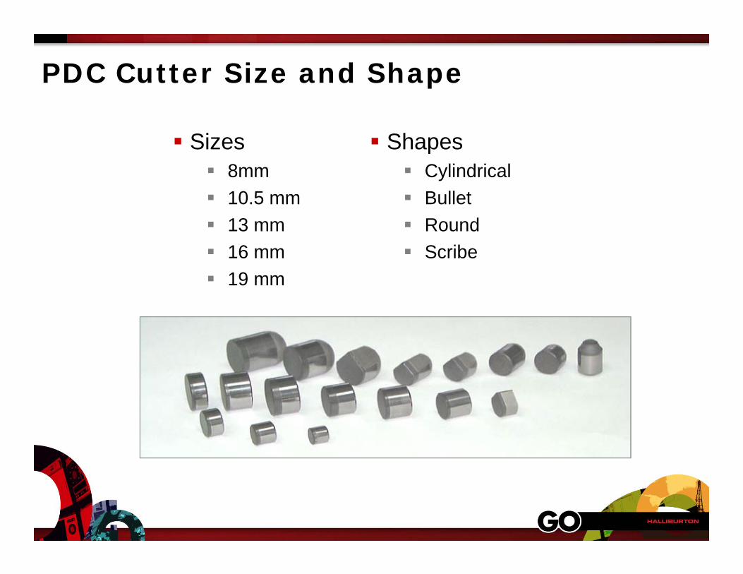
PDC Cutter Size and Shape
Sizes 8mm 10.5 mm 13 mm 16 mm 19 mm
Shapes Cylindrical Bullet Round Scribe
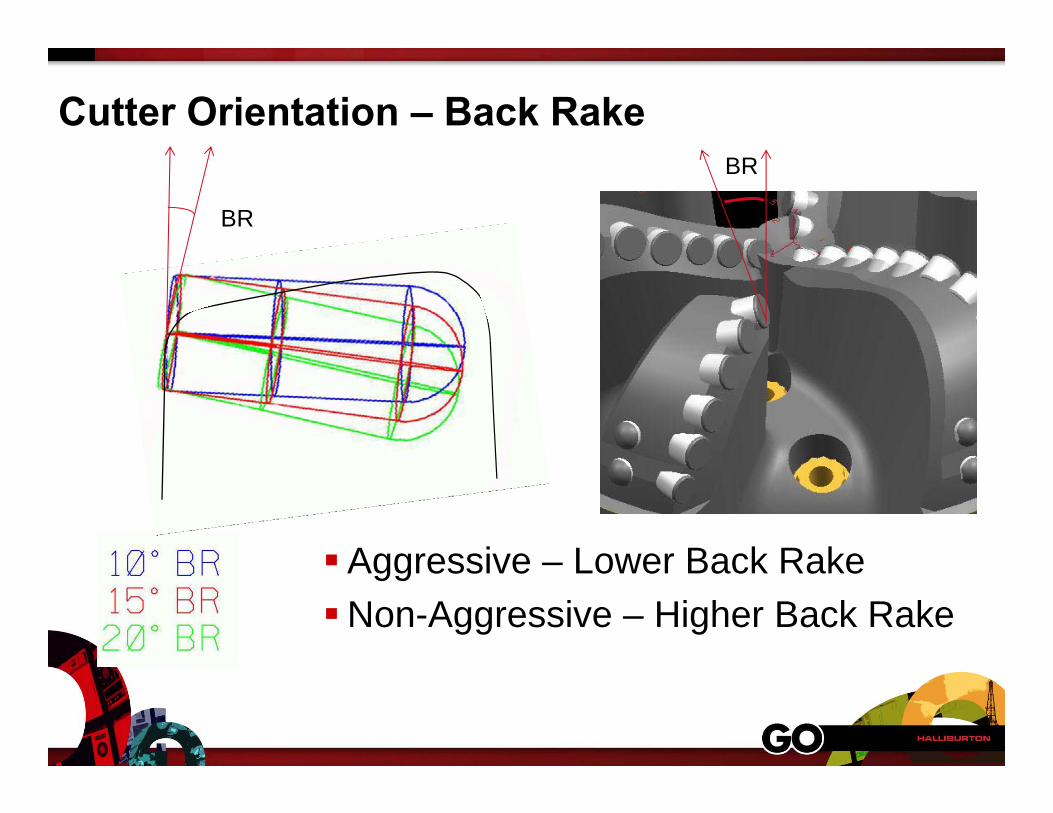
Cutter Orientation – Back Rake
BR
Aggressive – Lower Back RakeNon-Aggressive – Higher Back Rake
BR
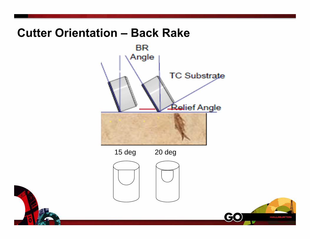
Cutter Orientation – Back Rake
15 deg 20 deg
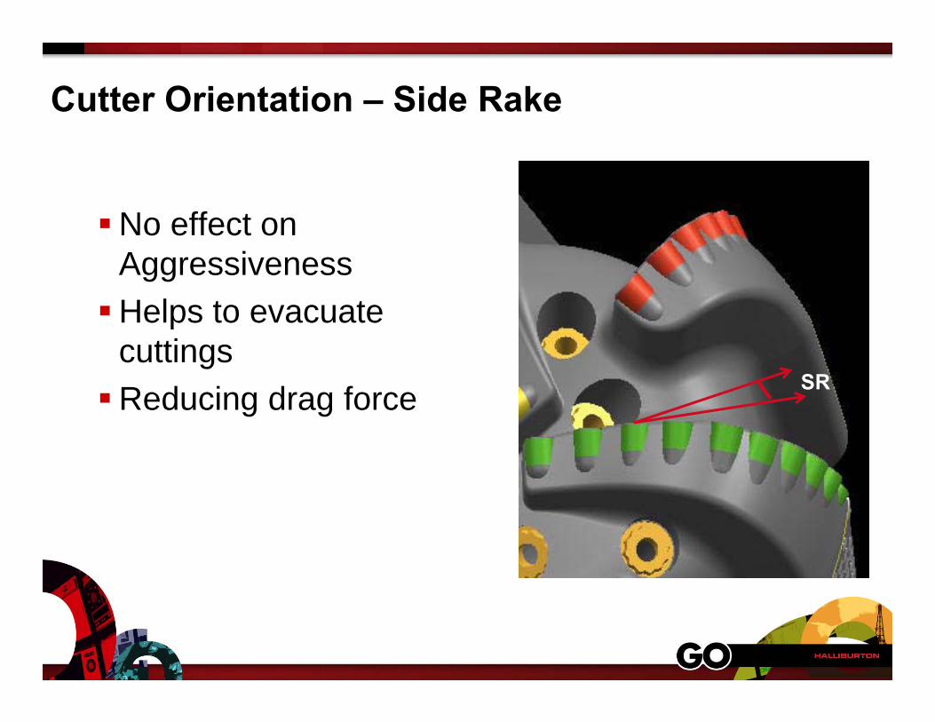
Cutter Orientation – Side Rake
No effect on AggressivenessHelps to evacuate
cuttingsReducing drag force SR
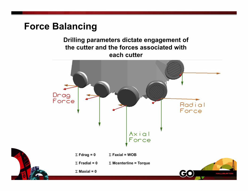
Force BalancingDrilling parameters dictate engagement of the cutter and the forces associated with
each cutter
Fradial = 0
Fdrag = 0 Faxial = WOB
Mcenterline = Torque
Maxial = 0
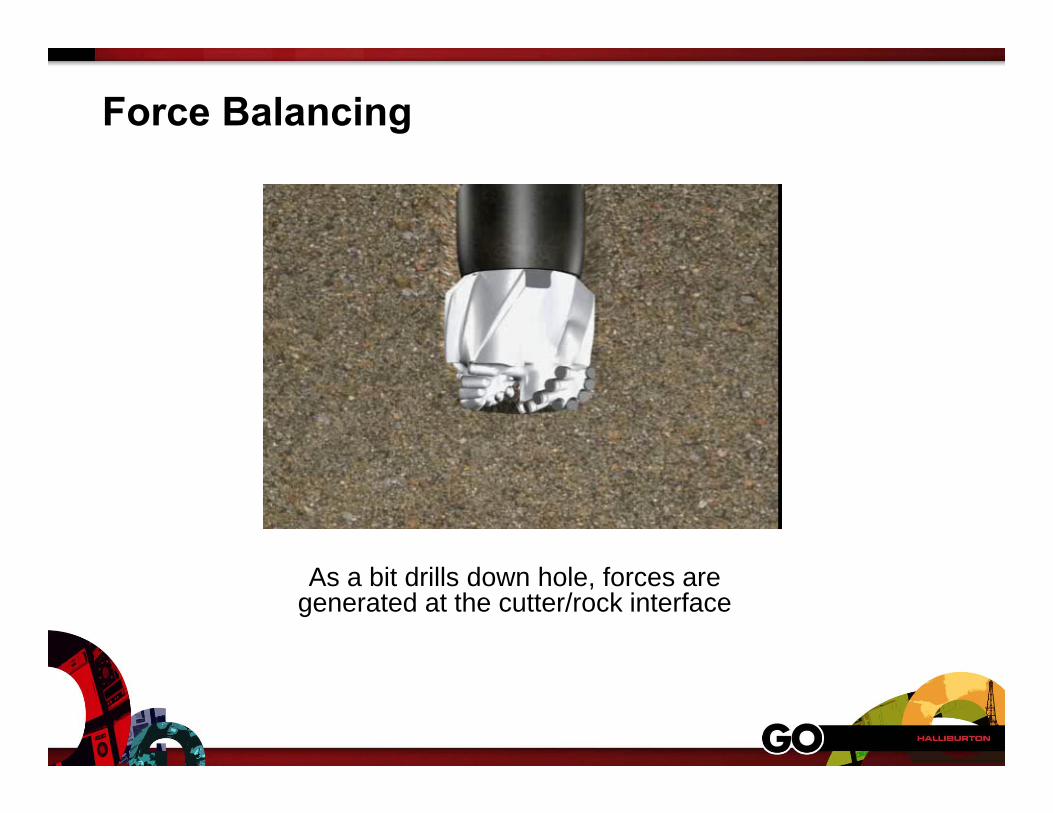
Force Balancing
As a bit drills down hole, forces are generated at the cutter/rock interface
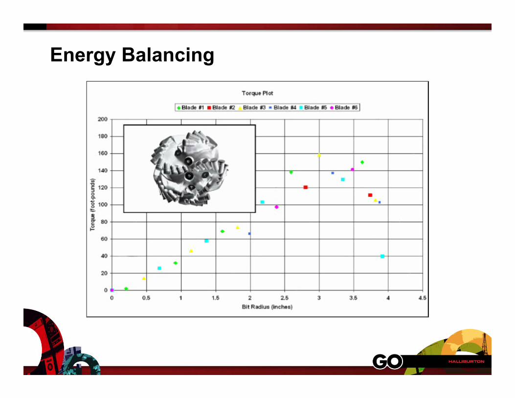
Energy Balancing
Energy Balancing
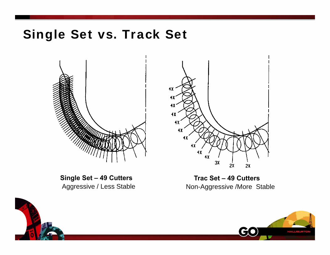
Single Set vs. Track Set
Single Set – 49 Cutters Trac Set – 49 CuttersAggressive / Less Stable Non-Aggressive /More Stable
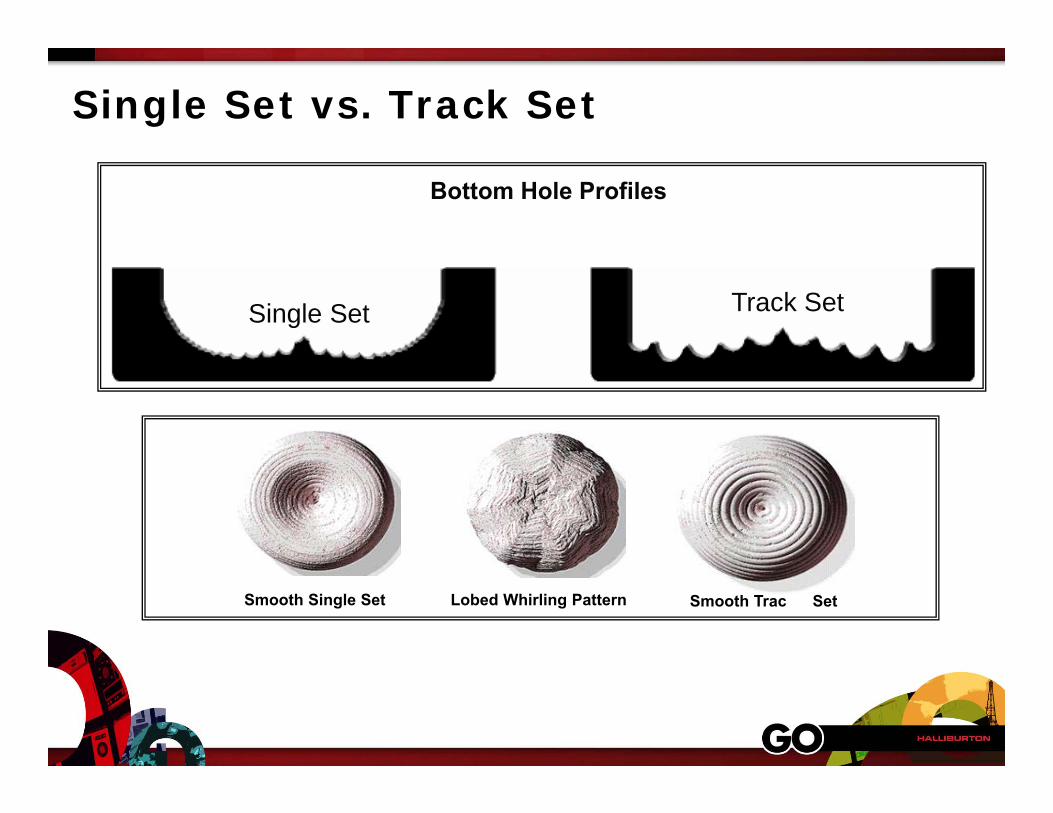
Single Set vs. Track Set
Bottom Hole Profiles
Single Set Track Set
Lobed Whirling PatternSmooth Single Set Smooth Trac Set
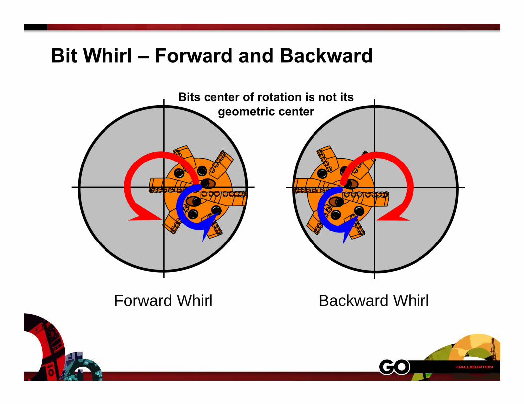
Bit Whirl – Forward and Backward
Forward Whirl Backward Whirl
Bits center of rotation is not its geometric center
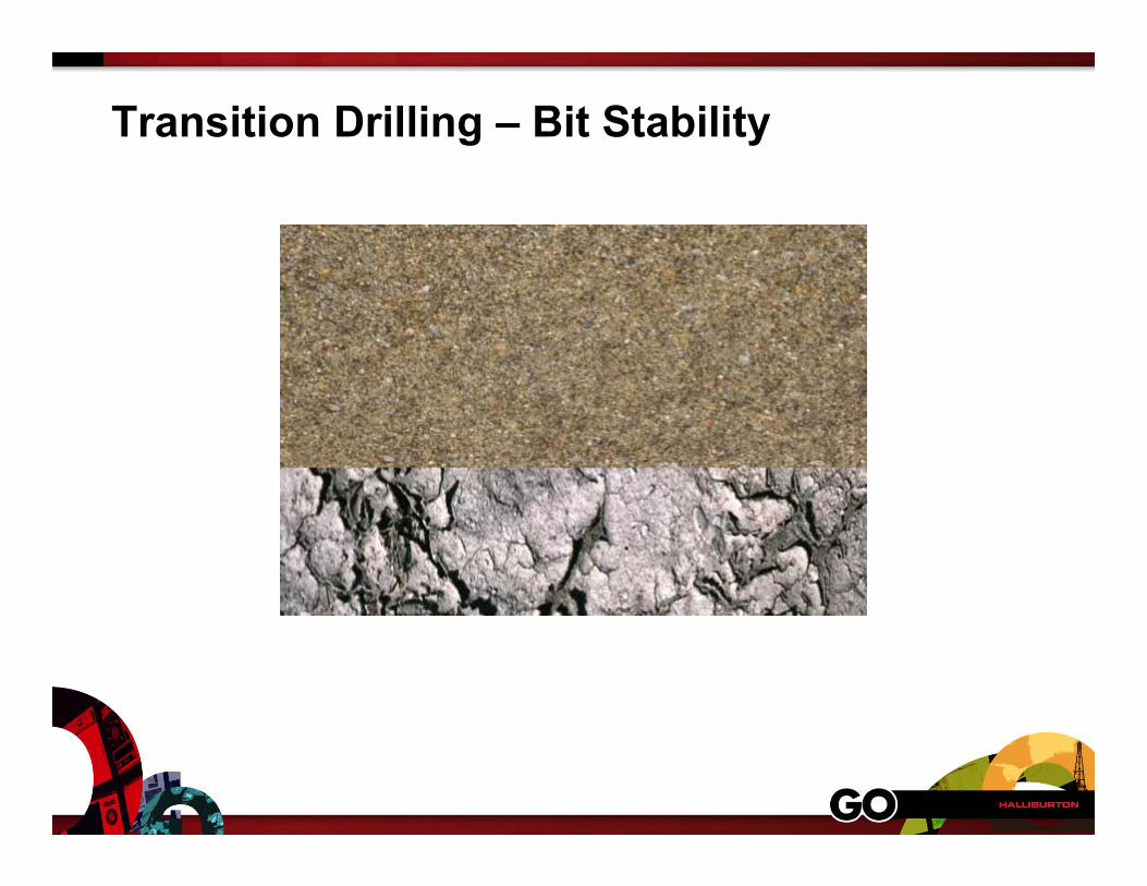
Transition Drilling – Bit Stability
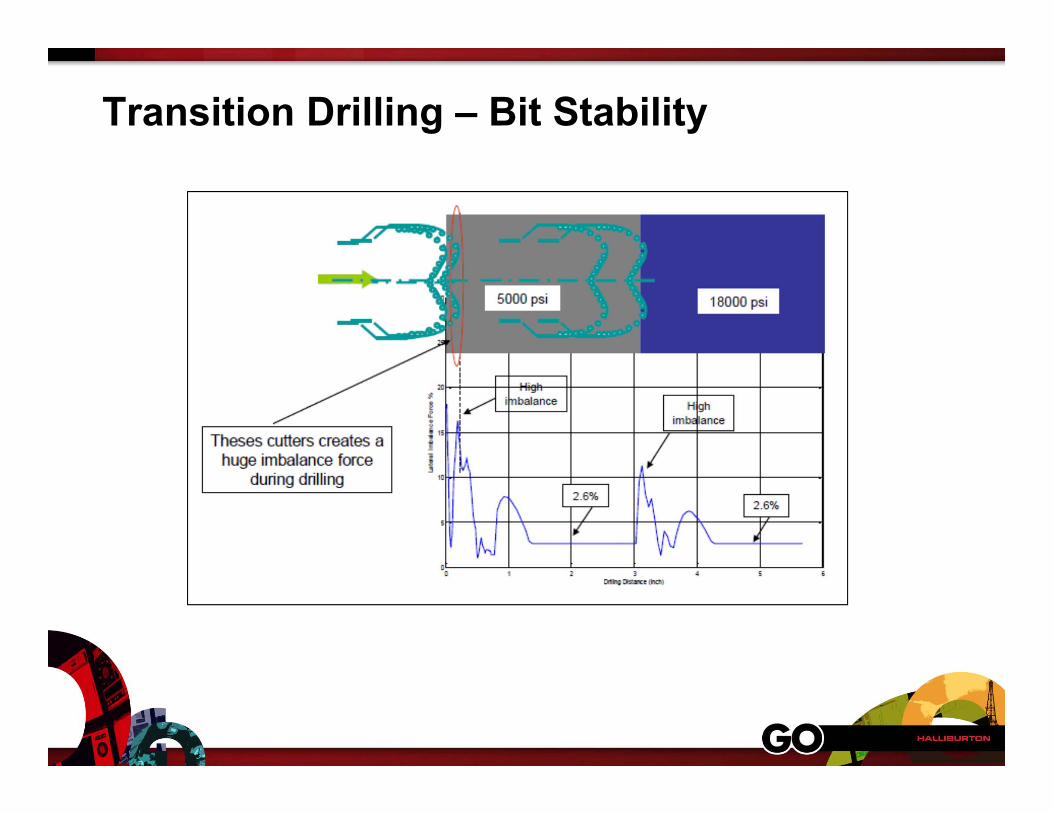
Transition Drilling – Bit Stability
Gauge Design
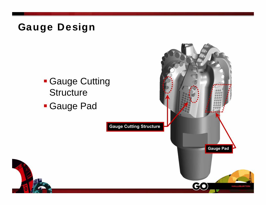
Gauge Design
Gauge Cutting StructureGauge Pad
Gauge Cutting Structure
Gauge Pad
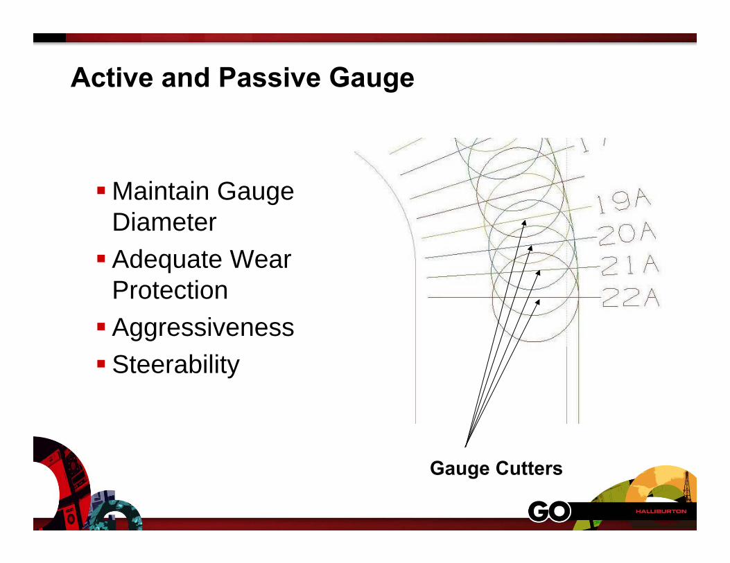
Active and Passive Gauge
Maintain Gauge DiameterAdequate Wear
ProtectionAggressivenessSteerability
Gauge Cutters
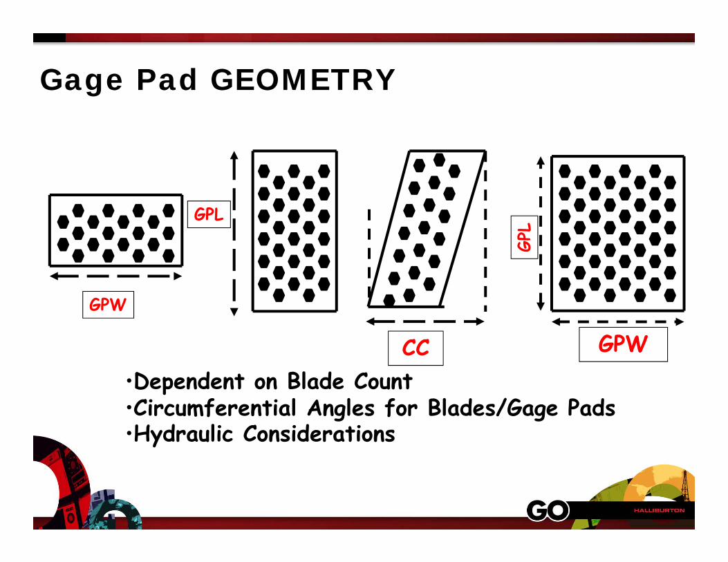
Gage Pad GEOMETRY
CC•Dependent on Blade Count•Circumferential Angles for Blades/Gage Pads•Hydraulic Considerations
GPW
GPL
GPW
GPL
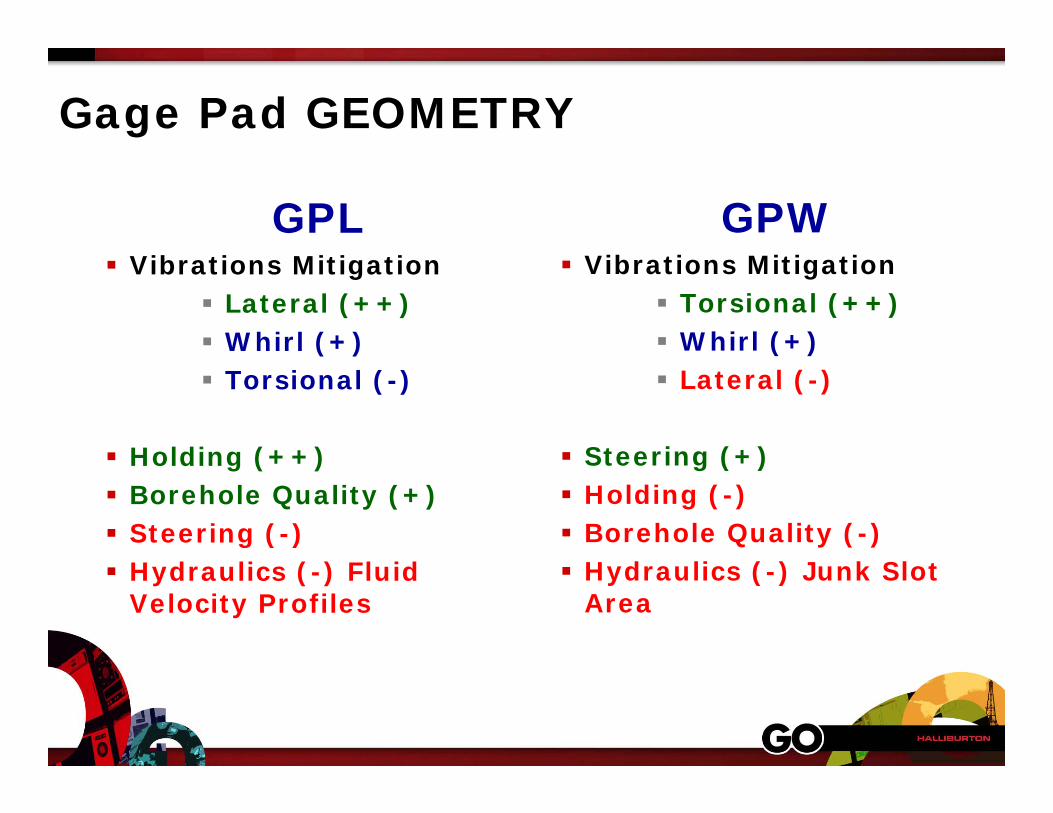
Gage Pad GEOMETRY
GPL Vibrations Mitigation
Lateral (++) Whirl (+) Torsional (-)
Holding (++) Borehole Quality (+) Steering (-) Hydraulics (-) Fluid
Velocity Profiles
GPW Vibrations Mitigation
Torsional (++) Whirl (+) Lateral (-)
Steering (+) Holding (-) Borehole Quality (-) Hydraulics (-) Junk Slot
Area
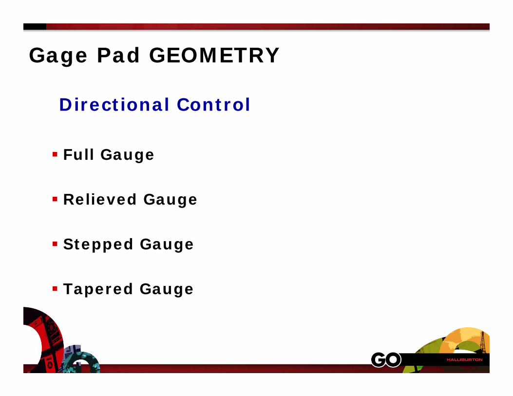
Gage Pad GEOMETRY
Directional Control
Full Gauge
Relieved Gauge
Stepped Gauge
Tapered Gauge
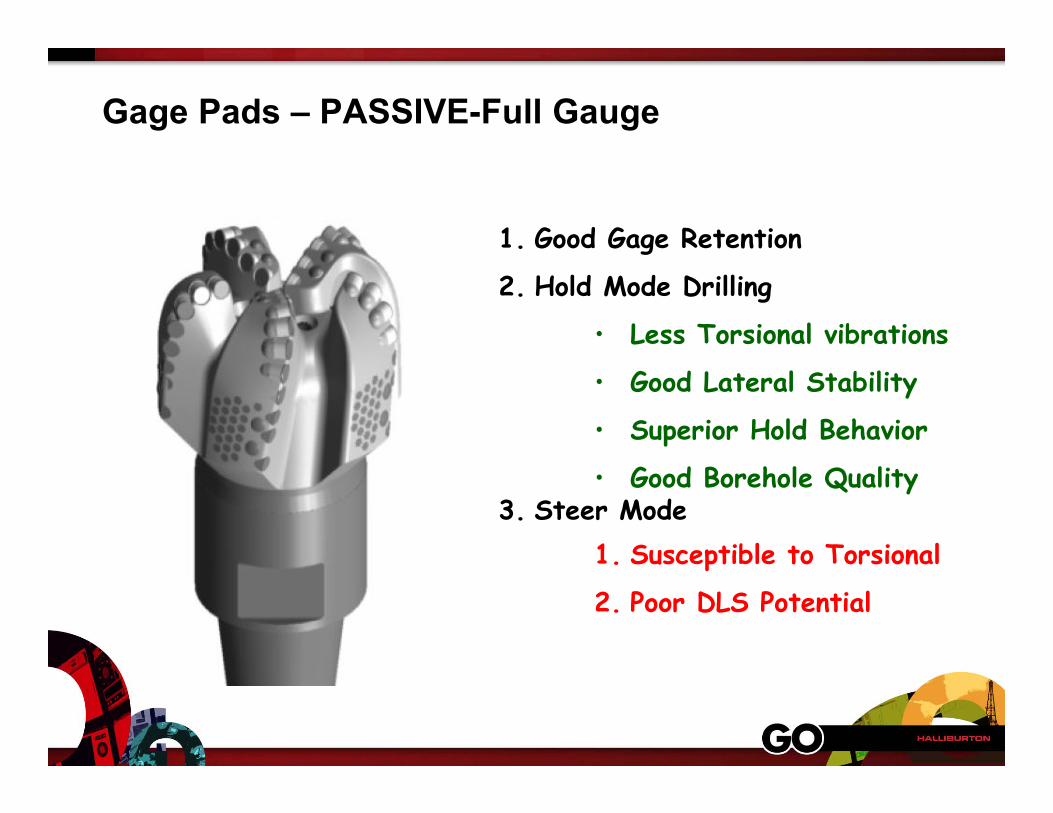
Gage Pads – PASSIVE-Full Gauge
1. Good Gage Retention
2. Hold Mode Drilling
• Less Torsional vibrations
• Good Lateral Stability
• Superior Hold Behavior
• Good Borehole Quality3. Steer Mode
1. Susceptible to Torsional
2. Poor DLS Potential
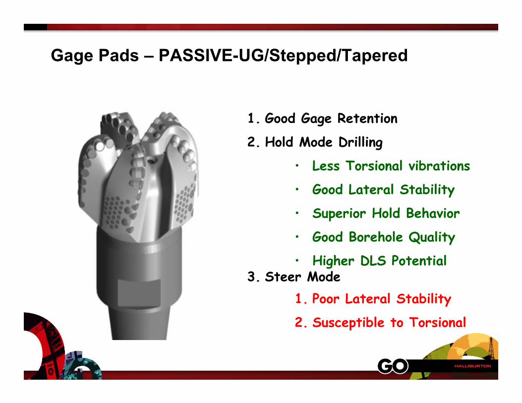
Gage Pads – PASSIVE-UG/Stepped/Tapered
1. Good Gage Retention
2. Hold Mode Drilling
• Less Torsional vibrations
• Good Lateral Stability
• Superior Hold Behavior
• Good Borehole Quality
• Higher DLS Potential3. Steer Mode
1. Poor Lateral Stability
2. Susceptible to Torsional
Fixed Cutter Bit Features
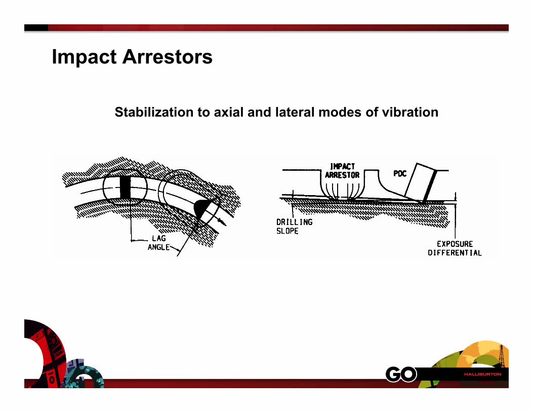
Impact Arrestors
Stabilization to axial and lateral modes of vibration

Impact Arrestors
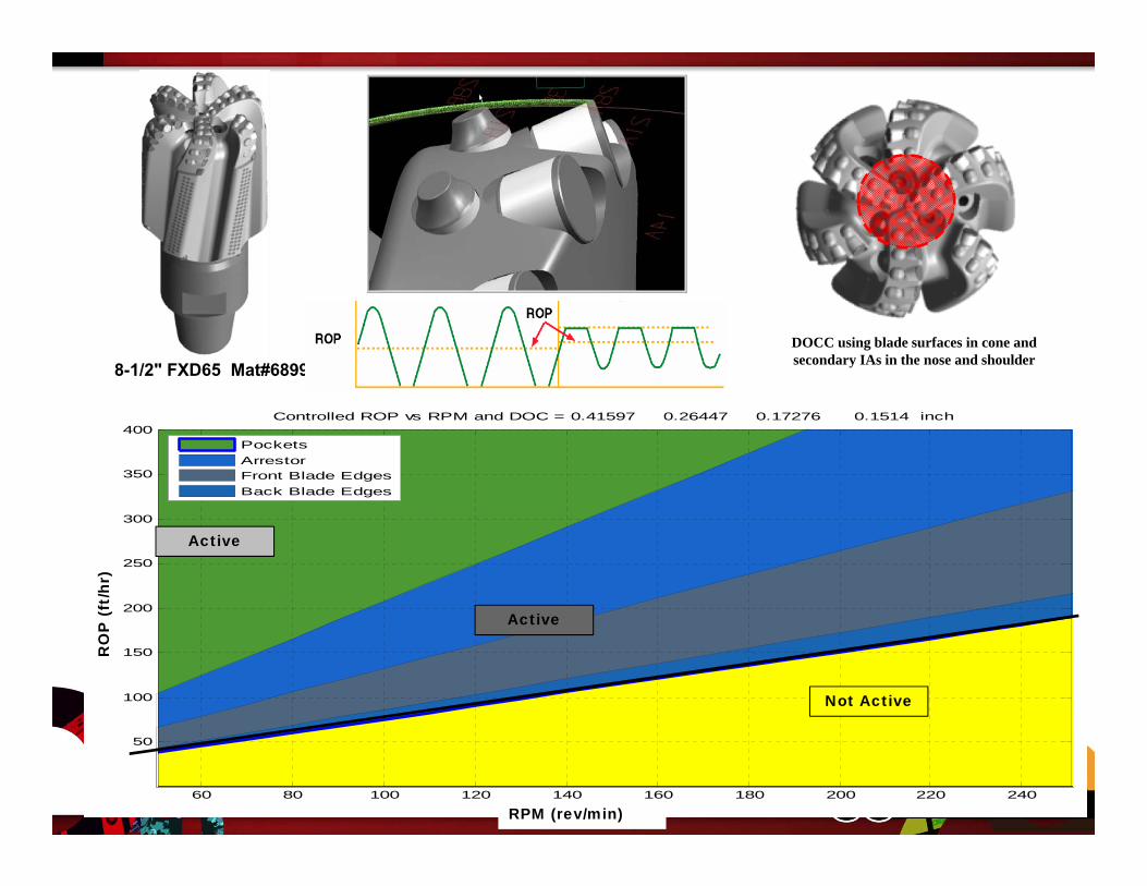
RPM
ROP (ft/h
r)
Controlled ROP vs RPM and DOC = 0.41597 0.26447 0.17276 0.1514 inch
60 80 100 120 140 160 180 200 220 240
50
100
150
200
250
300
350
400PocketsArrestorFront Blade EdgesBack Blade Edges
DOCC using blade surfaces in cone and secondary IAs in the nose and shoulder
RPM (rev/min)
Not Active
RO
P (
ft/h
r)
8-1/2" FXD65 Mat#689911
Active
Active
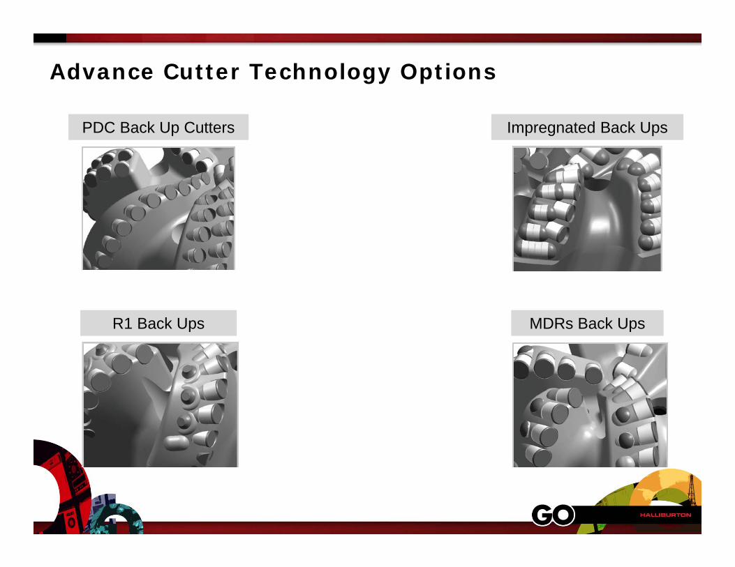
PDC Back Up Cutters
MDRs Back UpsR1 Back Ups
Impregnated Back Ups
Advance Cutter Technology Options
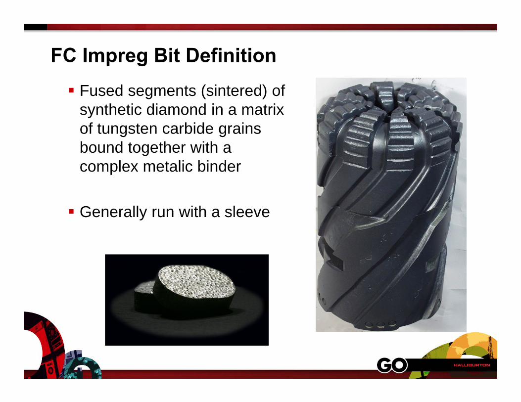
FC Impreg Bit Definition Fused segments (sintered) of
synthetic diamond in a matrix of tungsten carbide grains bound together with a complex metalic binder
Generally run with a sleeve
Aver
ageR
OP
(m/h
)
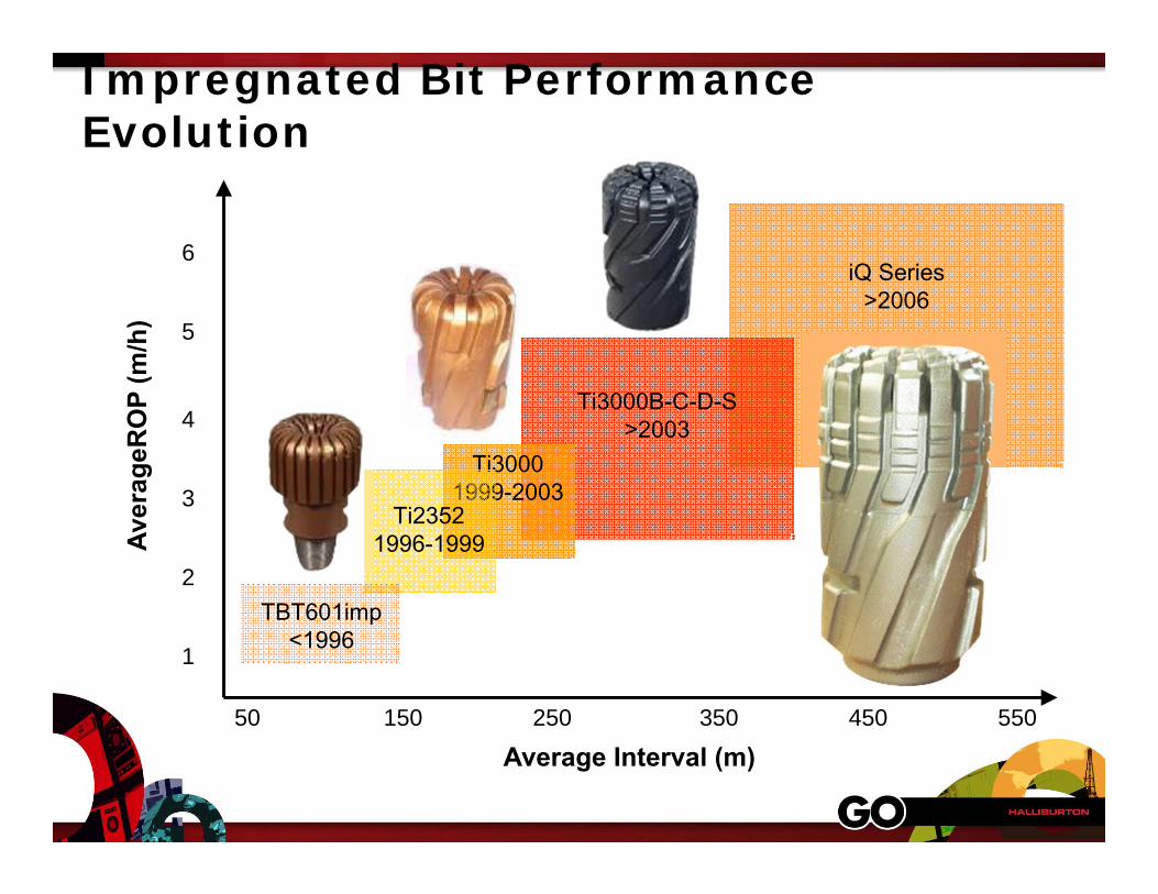
Impregnated Bit Performance Evolution
Average Interval (m)
1
2
3
4
5
6
50 150 250 350 450 550
iQ Series>2006
Ti3000B-C-D-S>2003
Ti30001999-2003
Ti23521996-1999
TBT601imp<1996
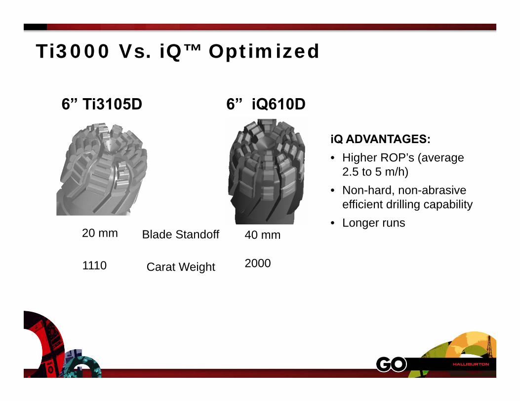
6” Ti3105D
20 mm
1110
40 mm
2000
6” iQ610D
iQ ADVANTAGES:• Higher ROP’s (average
2.5 to 5 m/h) • Non-hard, non-abrasive
efficient drilling capability• Longer runs
Ti3000 Vs. iQ™ Optimized
Blade Standoff
Carat Weight
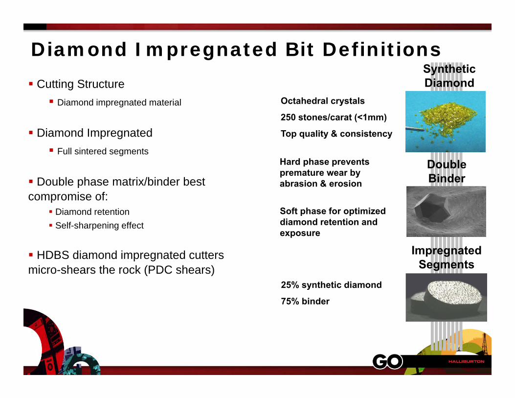
Diamond Impregnated Bit Definitions Cutting Structure Diamond impregnated material
Diamond Impregnated Full sintered segments
Double phase matrix/binder best compromise of:
Diamond retention Self-sharpening effect
HDBS diamond impregnated cutters micro-shears the rock (PDC shears)
Synthetic Diamond
Double Binder
Impregnated Segments
Octahedral crystals
250 stones/carat (<1mm)
Top quality & consistency
Soft phase for optimized diamond retention and exposure
Hard phase prevents premature wear by abrasion & erosion
25% synthetic diamond
75% binder
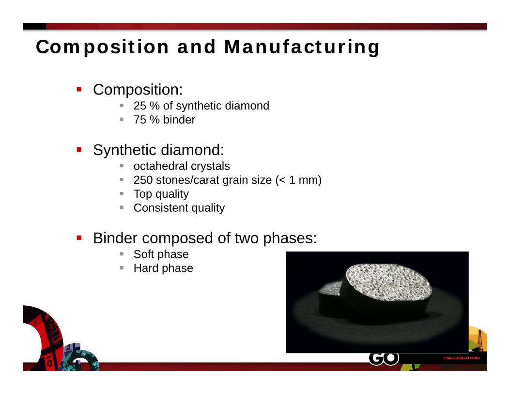
Composition and Manufacturing
Composition: 25 % of synthetic diamond 75 % binder
Synthetic diamond: octahedral crystals 250 stones/carat grain size (< 1 mm) Top quality Consistent quality
Binder composed of two phases: Soft phase Hard phase
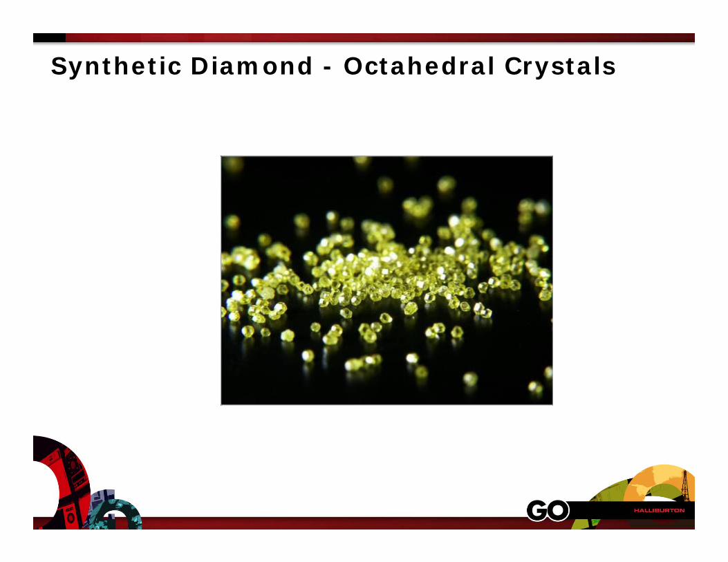
Synthetic Diamond - Octahedral Crystals
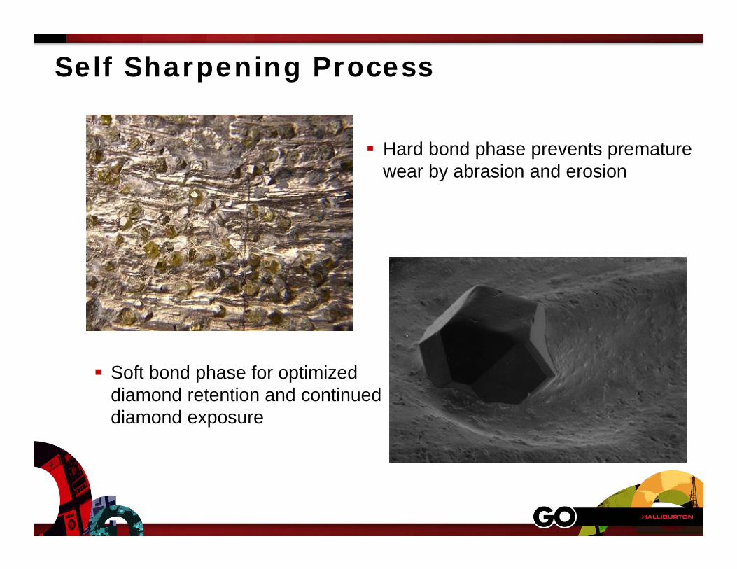
Self Sharpening Process
Hard bond phase prevents premature wear by abrasion and erosion
Soft bond phase for optimized diamond retention and continued diamond exposure
Impreg Applications
Medium hard to very hard Medium abrasive to very abrasive Including particular applications
Interbedded formations (abrasive/plastic) Drillability issues due to high confinement pressure
(deep and/or high MW)
Turbine or motor (and rotary) Directional: kick-off, build-up, horizontal

Suggested Application
Abrasiveness
Run length
35kpsi
10kpsi
Compressive Strength

Micro-shearingShearing
Drilling Mechanics
PDC Bit Impreg BitRPM = 90 - 160 RPM = 500 – 1500
WOB = Less Than PDC
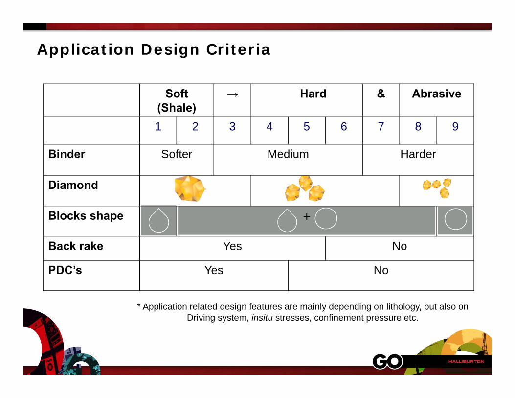
* Application related design features are mainly depending on lithology, but also on Driving system, insitu stresses, confinement pressure etc.
Application Design Criteria
Soft (Shale)
→ Hard & Abrasive
1 2 3 4 5 6 7 8 9
Binder Softer Medium Harder
Diamond
Blocks shape +
Back rake Yes No
PDC’s Yes No
PDC Cutter Technology
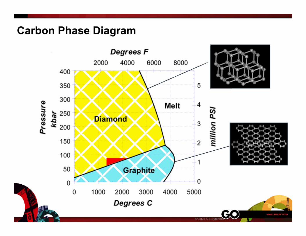
Carbon Phase Diagram
© 2007 US Synthetic
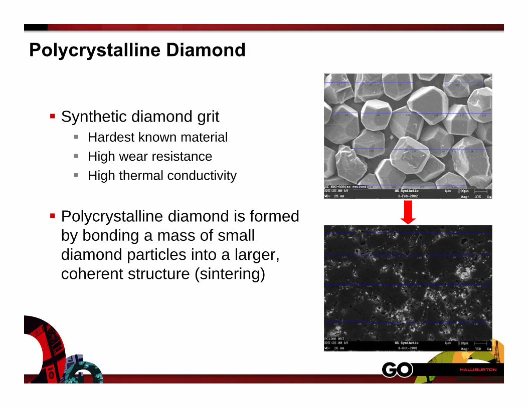
Polycrystalline Diamond
Synthetic diamond grit Hardest known material High wear resistance High thermal conductivity
Polycrystalline diamond is formed by bonding a mass of small diamond particles into a larger, coherent structure (sintering)
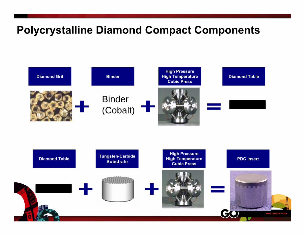
Polycrystalline Diamond Compact Components
Diamond Table Tungsten-CarbideSubstrate PDC Insert
High Pressure High Temperature
Cubic Press
Diamond Grit Binder Diamond TableHigh Pressure
High Temperature Cubic Press
Binder (Cobalt)

PDC Cutter Manufacturing
PyrophylliteCube
Steel Current Ring
SaltBushing
Graphite Heater
PyrophylliteCube
Steel Current Ring
SaltBushing
Graphite Heater
1,000,000 psi 2800 F
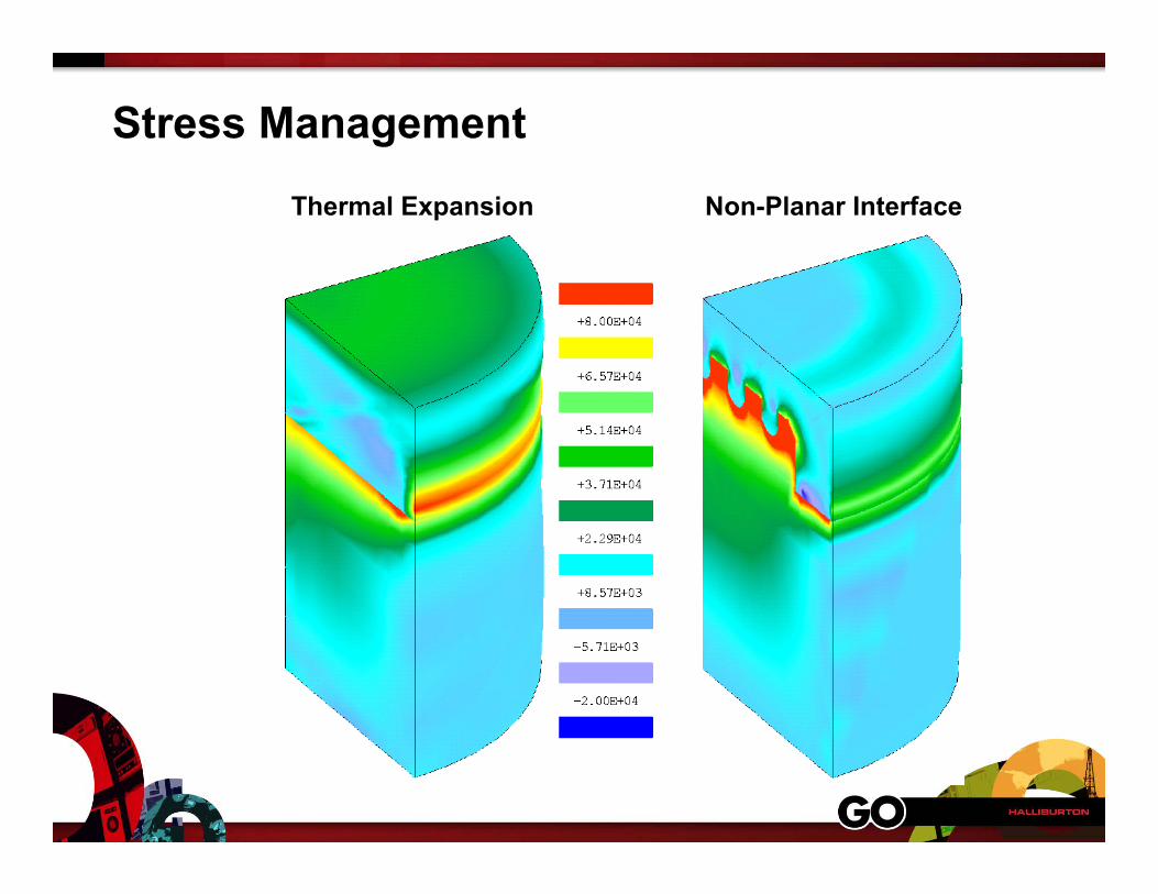
Stress Management
Thermal Expansion Non-Planar Interface
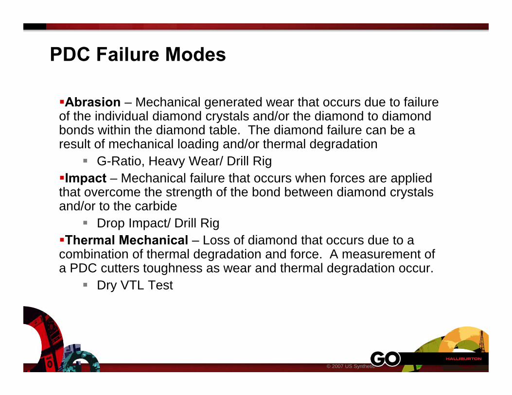
PDC Failure Modes
Abrasion – Mechanical generated wear that occurs due to failure of the individual diamond crystals and/or the diamond to diamond bonds within the diamond table. The diamond failure can be a result of mechanical loading and/or thermal degradation
G-Ratio, Heavy Wear/ Drill RigImpact – Mechanical failure that occurs when forces are applied that overcome the strength of the bond between diamond crystals and/or to the carbide
Drop Impact/ Drill RigThermal Mechanical – Loss of diamond that occurs due to a combination of thermal degradation and force. A measurement of a PDC cutters toughness as wear and thermal degradation occur.
Dry VTL Test
© 2007 US Synthetic
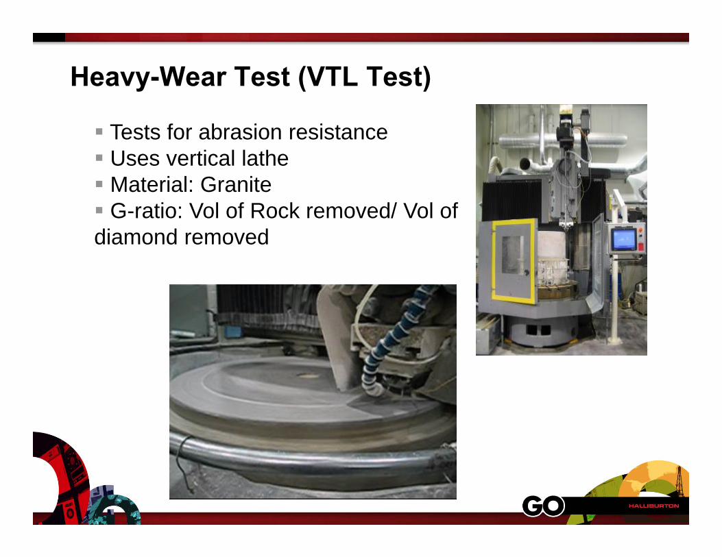
Heavy-Wear Test (VTL Test)
Tests for abrasion resistance Uses vertical lathe Material: Granite G-ratio: Vol of Rock removed/ Vol ofdiamond removed
CT-A CT-D CT-F
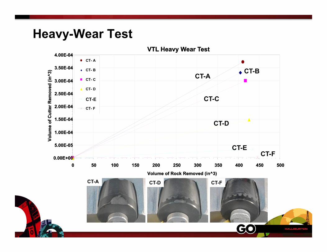
Heavy-Wear TestVTL Heavy Wear Test
0.00E+00
5.00E-05
1.00E-04
1.50E-04
2.00E-04
2.50E-04
3.00E-04
3.50E-04
4.00E-04
0 50 100 150 200 250 300 350 400 450 500
Volume of Rock Removed (in^3)
Volu
me
of C
utte
r Rem
oved
(in^
3)
1613 ELITE RC (2001)
1613 ELITE DRC (2001)
1613 CRC (9/2002)
1613 CT-21 (3/2004)
1613 Z3 (CT-27) (9/2004)
1613 CT-36 (8/2006)
2001
2002
20042006
2004
VTL Heavy Wear Test
0.00E+00
5.00E-05
1.00E-04
1.50E-04
2.00E-04
2.50E-04
3.00E-04
3.50E-04
4.00E-04
0 50 100 150 200 250 300 350 400 450 500
Volume of Rock Removed (in^3)
Volu
me
of C
utte
r Rem
oved
(in^
3)
CT- A
CT- B
CT- C
CT- D
CT-E
CT- F
CT-A
CT-C
CT-ECT-F
CT-D
CT-B
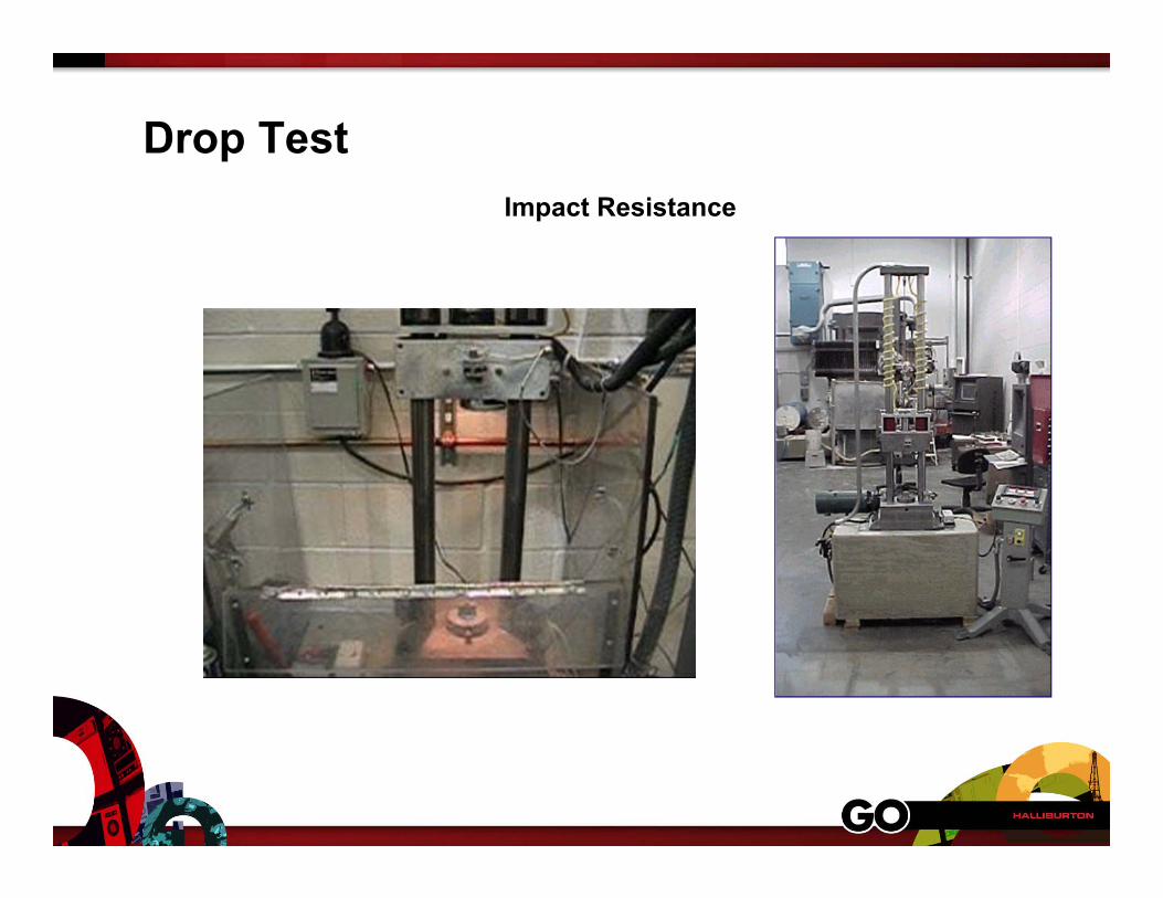
Drop TestImpact Resistance
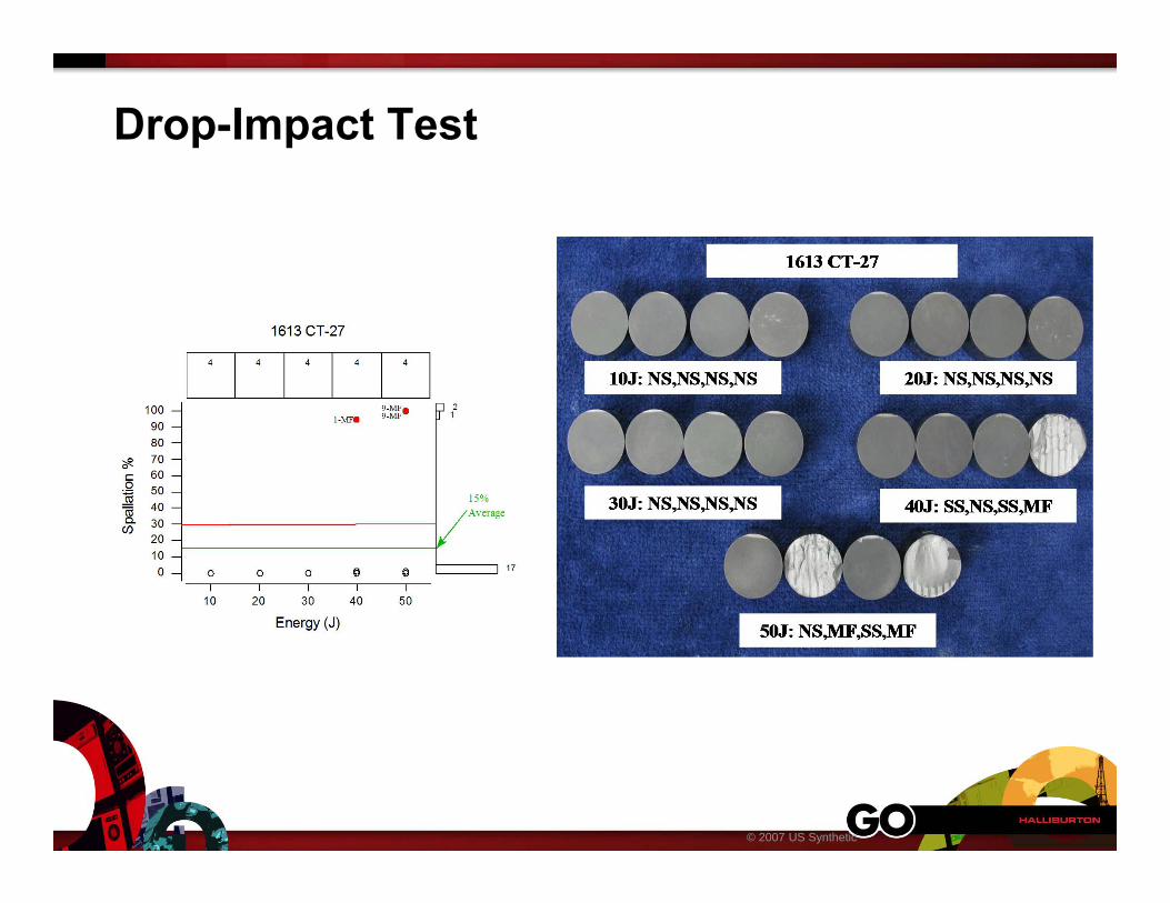
Drop-Impact Test
© 2007 US Synthetic
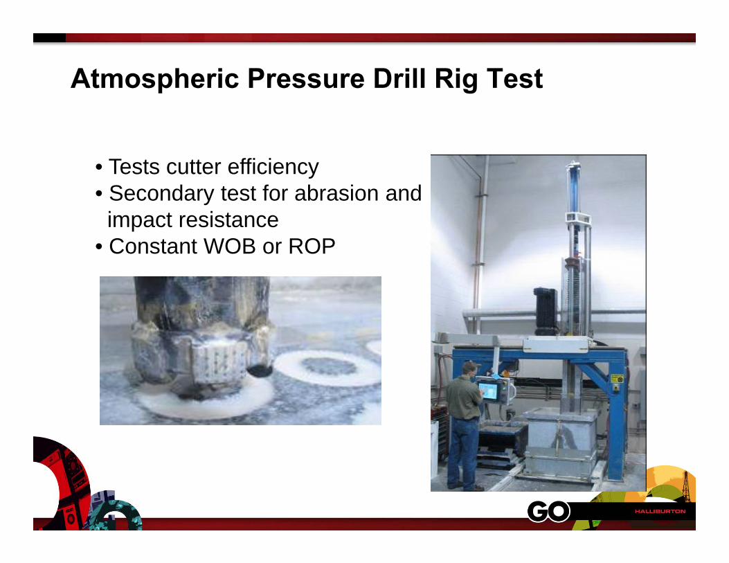
Atmospheric Pressure Drill Rig Test
• Tests cutter efficiency• Secondary test for abrasion andimpact resistance
• Constant WOB or ROP
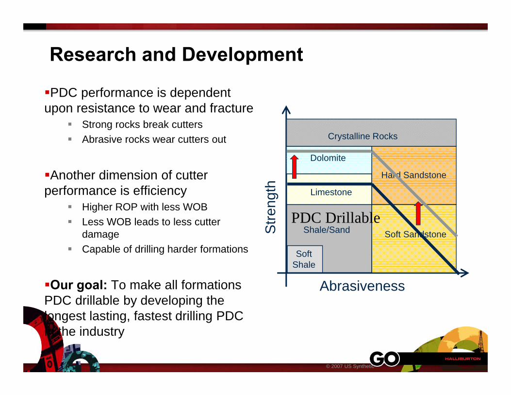
Research and Development
PDC performance is dependent upon resistance to wear and fracture
Strong rocks break cutters Abrasive rocks wear cutters out
Another dimension of cutter performance is efficiency
Higher ROP with less WOB Less WOB leads to less cutter
damage Capable of drilling harder formations
Our goal: To make all formations PDC drillable by developing the longest lasting, fastest drilling PDC in the industry
© 2007 US Synthetic
AbrasivenessS
treng
th Limestone
Shale/Sand
SoftShale
Hard Sandstone
Soft Sandstone
Dolomite
Crystalline Rocks
PDC Drillable