Embed Size (px)
Citation preview
FC 4-211-03F 3 MAY 2016
FACILITIES CRITERIA (FC)
APPROVED FOR PUBLIC RELEASE; DISTRIBUTION UNLIMITED
AIR FORCE FIGHTER ENGINE
MAINTENANCE FACILITY
FC 4-211-03F 3 MAY 2016
FACILITIES CRITERIA (FC)
AIR FORCE
FIGHTER ENGINE MAINTENANCE FACILITY
Any copyrighted material included in this FC is identified at its point of use. Use of the copyrighted material apart from this FC must have the permission of the copyright holder. U.S. ARMY CORPS OF ENGINEERS NAVAL FACILITIES ENGINEERING COMMAND AIR FORCE CIVIL ENGINEER CENTER (Preparing Activity) Record of Changes (changes are indicated by \1\ ... /1/)
Change No. Date Location
FC 4-211-03F 3 MAY 2016
FOREWORD Facilities Criteria (FC) provide functional requirements (i.e., defined by users and operational needs of a particular facility type) for specific DoD Component(s), and are intended for use with unified technical requirements published in DoD Unified Facilities Criteria (UFC). FC are applicable only to the DoD Component(s) indicated in the title, and do not represent unified DoD requirements. Differences in functional requirements between DoD Components may exist due to differences in policies and operational needs. All construction outside of the United States is also governed by Status of Forces Agreements (SOFA), Host Nation Funded Construction Agreements (HNFA), and in some instances, Bilateral Infrastructure Agreements (BIA.) Therefore, the acquisition team must ensure compliance with the most stringent of the FC, the SOFA, the HNFA, and the BIA, as applicable. Because FC are coordinated with unified DoD technical requirements, they form an element of the DoD UFC system applicable to specific facility types. The UFC system is prescribed by MIL-STD 3007 and provides planning, design, construction, sustainment, restoration, and modernization criteria, applicable to the Military Departments, Defense Agencies, and the DoD Field Activities. The UFC System also includes technical requirements and functional requirements for specific facility types, both published as UFC documents and FC documents. FC are living documents and will be periodically reviewed, updated, and made available to users as part of the Services’ responsibility for providing criteria for military construction. Headquarters, U.S. Army Corps of Engineers (HQUSACE), Naval Facilities Engineering Command (NAVFAC), and the Air Force Civil Engineer Center (AFCEC) are responsible for administration of the UFC system. Defense agencies should contact the preparing service for document interpretation and improvements. Technical content is the responsibility of the cognizant DoD working group. Recommended changes with supporting rationale should be sent to the respective service proponent office using the following electronic form: Criteria Change Request. The form is also accessible from the Internet site listed below. FC are effective upon issuance and are distributed only in electronic media from the following source:
Whole Building Design Guide web site http://dod.wbdg.org/. Refer to UFC 1-200-01, General Building Requirements, for implementation of new issuances on projects. AUTHORIZED BY: EDWIN H. OSHIBA, SES, DAF Deputy Director of Civil Engineers DCS/Logistics, Engineering & Force Protection
FC 4-211-03F 3 MAY 2016
FACILITIES CRITERIA (FC) NEW SUMMARY SHEET
Document: FC 4-211-03F, Fighter Engine Maintenance Facility
Superseding: None.
Description: This FC provides requirements for evaluating, planning, programming, and designing fighter engine maintenance facilities. The information in this FC applies to the design of all new construction projects, to include additions, alterations, and renovation projects in the continental United States (CONUS) and outside the continental United States (OCONUS). It also applies to the procurement of design/build services for the above-noted projects. Alteration and renovation projects should update existing facilities to meet the guidance and criteria within budgetary constraints.
Reasons for Document: This FC is the initial release to establish requirements for a fighter engine maintenance facility. It defines the criteria for determining appropriately sized, flexible, cost optimized, durable, quality-designed facilities on a life cycle basis to support the mission. Impact: This FC will facilitate and standardize the design of fighter engine maintenance facilities throughout the Air Force.
It will provide more complete and consistent project requirements and will expedite the programming and design of facilities and reduce initial design cost.
The improved performance-based criteria and coordination with the Air Force request-for-proposal (RFP) template will reduce design-build proposals.
Unification Issues: None.
FC 4-211-03F 3 MAY 2016
i
TABLE OF CONTENTS
CHAPTER 1 INTRODUCTION ....................................................................................... 1
1-1 GENERAL INFORMATION. ................................................................................. 1
1-2 GENERAL BUILDING REQUIREMENTS. ........................................................... 1
1-3 REFERENCES. .................................................................................................... 1
1-4 INSTRUCTIONS. .................................................................................................. 1
1-4.1 Standard Facility Prototype Tools. ................................................................. 2
1-4.2 Facilities Criteria. ........................................................................................... 2 Notional Site. .......................................................................................... 2 Composite Facility Adjacency Diagram(s). ............................................. 2 Modules. ................................................................................................. 2
Module Flexibility/Adjustments. .............................................................. 3 Room Data Sheets. ................................................................................ 3
1-4.3 Programming Sheet(s). ................................................................................. 3 1-4.4 Facility Drawings – BIM. ................................................................................ 4 1-4.5 Additional and Alterations. ............................................................................. 4
CHAPTER 2 SITE AND OVERALL ADJACENCY ......................................................... 5
2-1 GENERAL FACILITY OVERVIEW. ...................................................................... 5
2-1.1 AFCFS........................................................................................................... 5 2-1.2 Facility Users/Occupants. .............................................................................. 5
2-1.3 Operational Aspects. ..................................................................................... 5
2-2 NOTIONAL Site. .................................................................................................. 5 2-2.1 Site Location and Orientation. ....................................................................... 5
2-2.2 Vehicular and Pedestrian Circulation. ........................................................... 6
2-3 COMPOSITE FACILITY ADJACENCY (FIGURE 2-2). ........................................ 6
CHAPTER 3 FACILITY REQUIREMENTS AND CRITERIA .......................................... 9
3-1 MODULE A - ENGINE SHOP BAY MODULE ..................................................... 9
3-1.1 Function and Adjacency ................................................................................ 9 3-1.2 Engine Shop Bay Floor Plan (Figure 3-2). ................................................... 10 3-1.3 Data Sheets. ................................................................................................ 11
3-2 MODULE B – ENGINE SHOP SUPPORT MODULE. ........................................ 16 3-2.1 Function and Adjacency (Figure 3-8). ......................................................... 16 3-2.2 Engine Shop Support Floor Plan (Figure 3-9). ............................................ 17 3-2.3 Data Sheets. ................................................................................................ 18
FC 4-211-03F 3 MAY 2016
ii
3-3 MODULE C – BREAK ROOM MODULE. .......................................................... 21 3-3.1 Function and Adjacency (Figure 3-13). ....................................................... 21 3-3.2 Break Room Floor Plan. .............................................................................. 22 3-3.3 Data Sheets ................................................................................................. 23
3-4 MODULE D – FLIGHT CHIEF/TRAINING ADMINISTRATION MODULE ......... 24
3-4.1 Function and Adjacency (Figure 3-16). ....................................................... 24 3-4.2 Flight Chief/Training Administration Floor Plan (Figure 3-17). ..................... 25 3-4.3 Data Sheets. ................................................................................................ 26
3-5 MODULE E – TOILETS/SHOWERS/LOCKERS MODULE .............................. 32 3-5.1 Function and Adjacency .............................................................................. 32
3-5.2 Toilets/Showers/Lockers Floor Plan (Figure 3-25). ..................................... 33 3-5.3 Data Sheet. ................................................................................................. 34
3-6 MODULE F – BUILDING SUPPORT MODULE ................................................. 35
3-6.1 Function and Adjacency .............................................................................. 35 3-6.2 Building Support Floor Plan (Figure 3-28). .................................................. 36 3-6.3 Data Sheets. ................................................................................................ 37
APPENDIXES
APPENDIX A – REFERENCES .................................................................................... 43 APPENDIX B – BEST PRACTICES ............................................................................. 51
APPENDIX C –BIM AND PDF DRAWINGS LINK ........................................................ 53 APPENDIX D – AIR FORCE MILCON SUSTAINABILITY REQUIREMENTS SCORESHEETS ........................................................................................................... 55
FIGURES Figure 2-1 Notional Site Diagram ................................................................................... 7 Figure 2-2 Functional Adjacency Diagram ..................................................................... 8 Figure 3-1 Module A Adjacency Diagram ........................................................................ 9
Figure 3-2 Module A Floor Plan and Axonometric ........................................................ 10 Figure 3-3 A1 Engine Shop Bay Room Data Sheet ..................................................... 11 Figure 3-4 A2 Parts Cleaning Room Data Sheet .......................................................... 12 Figure 3-5 A3 Bearing Room Data Sheet ..................................................................... 13 Figure 3-6 A4 Bench Stock/Supply/Tool Room Data Sheet ......................................... 14
Figure 3-7 A5 Exterior Engine Wash Bay - Covered Room Data Sheet ....................... 15 Figure 3-8 Module B Adjacency Diagram ..................................................................... 16 Figure 3-9 Module B Floor Plan and Axonometric ........................................................ 17 Figure 3-10 B1 Repair Section Chiefs Room Data Sheet ............................................. 18 Figure 3-11 B2 Ready Room Data Sheet ..................................................................... 19 Figure 3-12 B3 Jet Engine Intermediate Maintenance (JEIM) Room Data Sheet ........ 20 Figure 3-13 Module C Adjacency Diagram ................................................................... 21
FC 4-211-03F 3 MAY 2016
iii
Figure 3-14 Module C Floor Plan and Axonometric ..................................................... 22 Figure 3-15 C Break Room Data Sheet ........................................................................ 23 Figure 3-16 Module D Adjacency Diagram .................................................................... 24 Figure 3-17 Module D Floor Plan and Axonometric ..................................................... 25 Figure 3-18 D1 Flight Chief Room Data Sheet ............................................................. 26
Figure 3-19 D2 Flight Chief Admin Room Data Sheet .................................................. 27 Figure 3-20 D3 OEM/AFETS Room Data Sheet .......................................................... 28 Figure 3-21 D4 Conference Room Data Sheet ............................................................ 29 Figure 3-22 D5 Engine Management Room Data Sheet .............................................. 30 Figure 3-23 D6 Training Room Data Sheet .................................................................. 31
Figure 3-24 Module E Adjacency Diagram ................................................................... 32 Figure 3-25 Module E Floor Plan and Axonometric ...................................................... 33
Figure 3-26 E1-E7 Toilets/Showers/Lockers Room Data Sheet ................................... 34 Figure 3-27 Module F Adjacency Diagram ................................................................... 35 Figure 3-28 Module F Floor Plan & Axonometric ......................................................... 36 Figure 3-29 F1 Mechanical Room Data Sheet ............................................................. 37
Figure 3-30 F2 Electrical Room Data Sheet ................................................................. 38 Figure 3-31 F3 Communication Room Data Sheet...................................................... 39
Figure 3-32 F4 Fire Pump Room Data Sheet ............................................................... 40 Figure 3-33 Circulation Room Data Sheet .................................................................... 41

FC 4-211-03F 3 MAY 2016
iv
This Page Intentionally Left Blank
FC 4-211-03F 3 MAY 2016
1
CHAPTER 1 INTRODUCTION
1-1 GENERAL INFORMATION.
The standard facility prototype design program defines consistent facility requirements across the Air Force enterprise to expedite delivery of a facility. The objective is to deliver appropriately-sized, flexible, cost-optimized, durable, quality-designed facilities on a life cycle basis to support the Air Force mission.
This FC was provides standard facility prototype design criteria to assist Air Force planners in preparing and validating requirements for DD 1391, “FY __ Military Construction Project Data,” and to assist A-E design professionals with the approved project-specific design requirements. It is a source of basic programming and functional information for fighter engine maintenance facilities. This FC is consistent with Air Force Corporate Facility Standards (AFCFS) and UFCs, and complies with Air Force Manual (AFMAN) 32-1084, Facility Requirements. Together with the AFCFS, this FC defines Air Force expectations for project programming and A-E design decisions.
A standard facility prototype represents a shift in Air Force facility design philosophy toward maximizing use of open office space and systems furniture. This design approach allows maximum flexibility to reconfigure the building space as mission needs change. Where offices require sound attenuation, or physical or visual separation, evaluate the use of systems furniture or demountable partition walls in lieu of full-height hard wall construction. Maximizing open office space may require more systems furniture; funding must be listed on the 1391 as an FF&E cost. Comply with the latest Air Force policy on centralized procurement of systems and other furniture.
1-2 GENERAL BUILDING REQUIREMENTS.
Comply with UFC 1-200-01, General Building Requirements. UFC 1-200-01 defines applicability of model building codes and government-unique criteria for typical design disciplines and building systems, as well as for accessibility, antiterrorism, security, high performance and sustainability requirements, and safety. Use this FC in addition to UFC 1-200-01 and the UFCs and government criteria referenced herein.
1-3 REFERENCES.
Appendix A contains a list of related documents and references to be used with this FC. The publication date of the code or standard is not included. Use the latest available issuance of the reference.
1-4 INSTRUCTIONS.
The standard facility prototype was developed by determining personnel counts, allowable/authorized space/room sizes, adjacency diagrams between the functional spaces, and the overall facility space requirements. It establishes Air Force criteria for the facility type. Use these criteria together with other Air Force requirement documents such as AFIs and UFCs when programming and designing this facility type.
FC 4-211-03F 3 MAY 2016
2
Supplement this FC with thorough review by individual program managers and operations staff.
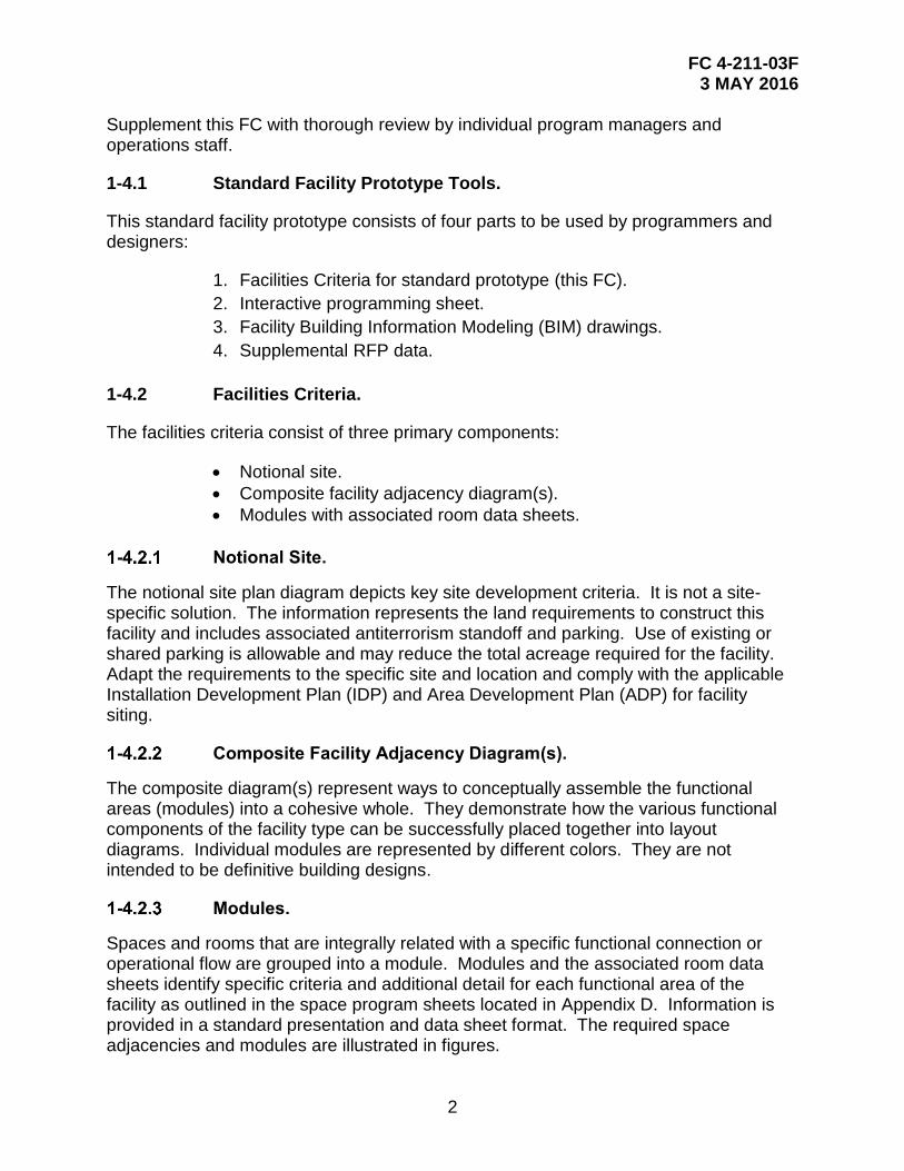
1-4.1 Standard Facility Prototype Tools.
This standard facility prototype consists of four parts to be used by programmers and designers:
1. Facilities Criteria for standard prototype (this FC).
2. Interactive programming sheet.
3. Facility Building Information Modeling (BIM) drawings.
4. Supplemental RFP data.
1-4.2 Facilities Criteria.
The facilities criteria consist of three primary components:
Notional site.
Composite facility adjacency diagram(s).
Modules with associated room data sheets.
Notional Site.
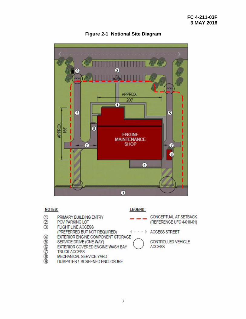
The notional site plan diagram depicts key site development criteria. It is not a site-specific solution. The information represents the land requirements to construct this facility and includes associated antiterrorism standoff and parking. Use of existing or shared parking is allowable and may reduce the total acreage required for the facility. Adapt the requirements to the specific site and location and comply with the applicable Installation Development Plan (IDP) and Area Development Plan (ADP) for facility siting.
Composite Facility Adjacency Diagram(s).
The composite diagram(s) represent ways to conceptually assemble the functional areas (modules) into a cohesive whole. They demonstrate how the various functional components of the facility type can be successfully placed together into layout diagrams. Individual modules are represented by different colors. They are not intended to be definitive building designs.
Modules.
Spaces and rooms that are integrally related with a specific functional connection or operational flow are grouped into a module. Modules and the associated room data sheets identify specific criteria and additional detail for each functional area of the facility as outlined in the space program sheets located in Appendix D. Information is provided in a standard presentation and data sheet format. The required space adjacencies and modules are illustrated in figures.
FC 4-211-03F 3 MAY 2016
3
The modules are a grouping of functional spaces and represent “Lego® blocks” to be used in a “kit-of-parts” design approach. Use the fixed modules as pre-assembled pieces of the facility “puzzle.” Assemble them to comply with the required adjacencies indicated in the diagrams and module plans. Arrange modules and create a configuration/composite building layout/plan responding to the constraints and opportunities of the specific site.
The resulting shape of the facility assembled from the standard facility prototype modules must provide construction efficiencies obtained from building proportions and overall configuration. The building footprint shall be organized and well composed. The building design must comply with the installation facility standards (architectural compatibility plan) and the AFCFS.
Module Flexibility/Adjustments.
Modules must be used as designed to the greatest extent possible, and must not be deconstructed or altered except as indicated herein. The intent of the standard facility prototype criteria is to avoid manipulation of the composition, functional relationships, adjacencies, and module sizes. Modules contain fixed attributes and must not be changed arbitrarily. Modules may be rotated, flipped, and reversed to accommodate an overall composition or site issue. When the fixed modules cannot be arranged to produce a constructible floor plan due to site constraints, it is permissible to slightly adjust a module proportion to create a constructible plan. Manipulating the module shape must not result in an overall increase in square feet or reduce the functionality of any module or the composite plan.
Some modules are linked to space requirements that increase or decrease in size based on the personnel count and equipment for a particular mission. In these cases, increase or decrease the size of the module to match the revised scope calculation. This may sometimes require minor adjustments in adjacent modules so that they properly fit together to create a constructible facility floor plan. Spaces must comply with any critical dimensions indicated on module plans. Manipulate as few modules as possible to create a constructible facility. The resulting composite plan must respect the established modules’ adjacencies and must not exceed the authorized project scope.
Room Data Sheets.
Specific requirements for each room, space, or area are provided on room data sheets that are located following their respective module. Information contained on the data sheets defines the functional and physical requirements for each of the spaces within the facility type.
1-4.3 Programming Sheet(s).
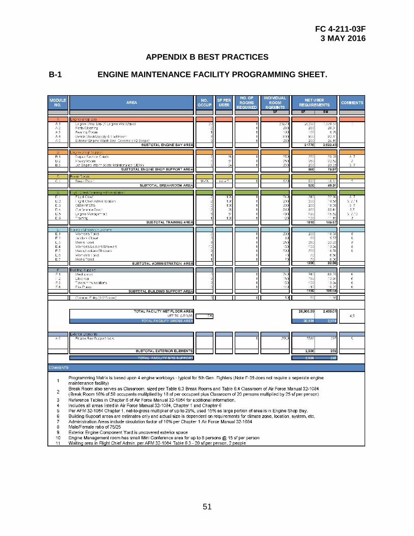
This tool is provided in two formats. The pdf programming sheet cited in Appendix B reflects the baseline standard facility program and is provided primarily as a reference. The additional interactive programming sheet provides a tool for planners and programmers. It allows the input of authorized personnel positions and special purpose spaces. Updated inputs are automatically calculated and provide new required square
FC 4-211-03F 3 MAY 2016
4
footage for each space and the estimated overall facility size. Appendix C contains a link for direct access to the interactive tool.
1-4.4 Facility Drawings – BIM.
This component of the standard facility prototype tool includes both a pdf version and Revit version of the modules and rooms. The spaces, rooms, and modules shown reflect the baseline standard facility program spreadsheet located in Appendix B. Drawings in this FC are exact copies of the larger BIM drawings and comply with the program scope. The BIM drawings provide a starting point for the digitization of building data and a starting point in the design and construction of a facility. BIM and pdf documents are found at the link provided in Appendix C.
1-4.5 Additional and Alterations.
For additions and alterations to existing facilities, use the adjacencies, sizing/scope, and detailed requirements contained in the site diagrams, module drawings, and room data sheets to the maximum extent possible. The functionality and adjacency of the modules are still valid, but may require some manipulation to fit into existing spaces. This standard may be modified slightly to accommodate the existing structure. Move non-structural walls to the greatest extent possible to open up space in the existing facilities to make them more receptive to the placement of the modules. The planner and designer will determine the most efficient means to balance the placement of modules within existing spaces or as a facility addition.
FC 4-211-03F 3 MAY 2016
5
CHAPTER 2 SITE AND OVERALL ADJACENCY
2-1 GENERAL FACILITY OVERVIEW.
A fighter engine maintenance facility is typically a one-story structure. It is a standalone facility that houses fifth-generation fighter engines and maintenance crews based upon four engine work bays – typical for fifth generation fighters. (Note: The F-35 does not require a separate engine maintenance facility). The engine maintenance facility will include the following modules: engine shop bay module, engine shop support module, flight chief/training administration module, break room module, toilet/shower/locker module, and building support module.
2-1.1 AFCFS.
Consult the AFCFS to determine quality standards for this facility group. This standard facility prototype is considered a Group 3 hierarchy.
2-1.2 Facility Users/Occupants.
This facility is operated by active duty, guard, and reserve military personnel, as well as contractor representatives from the selected engine provider. The number of occupants is approximately 25 personnel per shift (typically two shifts) used by both civilian and military personnel throughout the building
2-1.3 Operational Aspects.
Hours of operation for this facility type are user-driven and vary for different engine types. Amount of air traffic on base can also alter the hours of operation. Engines are delivered on flatbed trucks from offsite locations, delivered to engine bay for initial processing, and trailered to and from the flight line. An exterior wash bay is used before and/or after an engine is serviced.
2-2 NOTIONAL SITE.
The site diagram represents a notional layout to reflect site development requirements/criteria only. It is not an actual site design. Siting must comply with the Installation Development Plan (IDP) and Area Development Plan (ADP).
2-2.1 Site Location and Orientation.
Several factors must be analyzed to determine the most appropriate and cost-effective location for a facility, such as availability and capacity of required utilities, the mass/scale of the facility relative to adjacent structures, and noise issues. Emphasize operation, function, and safety when siting the facility. The preferred location for a fighter engine maintenance facility is immediately adjacent to the flight line, or in close proximity. Other facilities/functions sited in close proximity may include general purpose maintenance hangars and aircraft sunshades. Analyze and comply with airfield clearances, building setback restrictions, and line-of-sight restrictions from the adjacent flight line.
FC 4-211-03F 3 MAY 2016
6
The preferred orientation allows direct access to flight-line operations and ease of access for flight line vehicles and equipment. The approximate project area required for a four-bay shop is 4.00 acres, which includes antiterrorism standoff and parking.
2-2.2 Vehicular and Pedestrian Circulation.
Ensure convenient, safe vehicular access and circulation for personal vehicles and essential services, including operations, maintenance, deliveries, trash and garbage collection, and emergency services. Provide parking to accommodate the largest shift size plus an additional 40 percent for shift overlap. Separate service drives to the facility from parking circulation areas.
Locate sidewalk networks to provide convenient and safe pedestrian circulation from existing circulation elements of the project site to the new parking areas and doors of the facility.
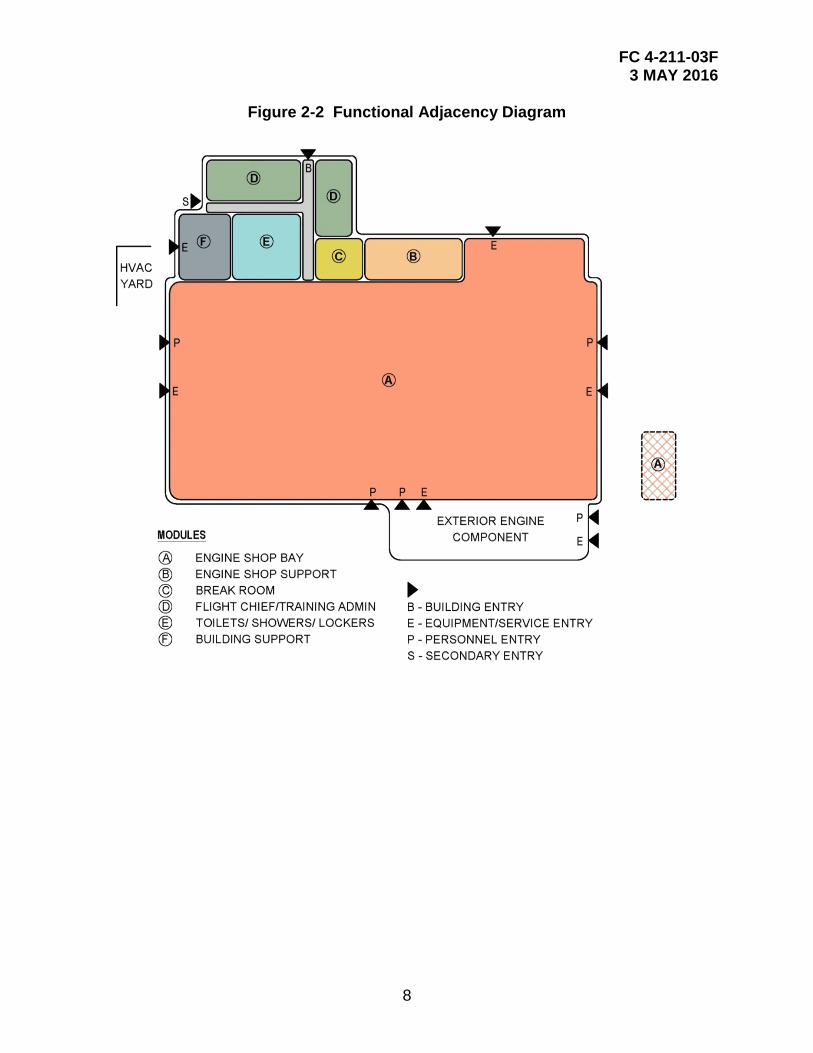
2-3 COMPOSITE FACILITY ADJACENCY (FIGURE 2-2).
This facility has a mixed use of occupants and many points of entry. A majority of administration and training personnel will enter through the main building entrance. Maintenance groups will be in/out of the engine shop bay throughout the day. If the facility is operational and occupied, spaces are left unlocked and accessible for transitioning engines to/from the flight line. Finalize any additional entrances when siting and orienting the building.
FC 4-211-03F 3 MAY 2016
7
Figure 2-1 Notional Site Diagram
FC 4-211-03F 3 MAY 2016
8
Figure 2-2 Functional Adjacency Diagram
FC 4-211-03F 3 MAY 2016
9
CHAPTER 3 FACILITY REQUIREMENTS AND CRITERIA
3-1 MODULE A - ENGINE SHOP BAY MODULE.
3-1.1 Function and Adjacency.
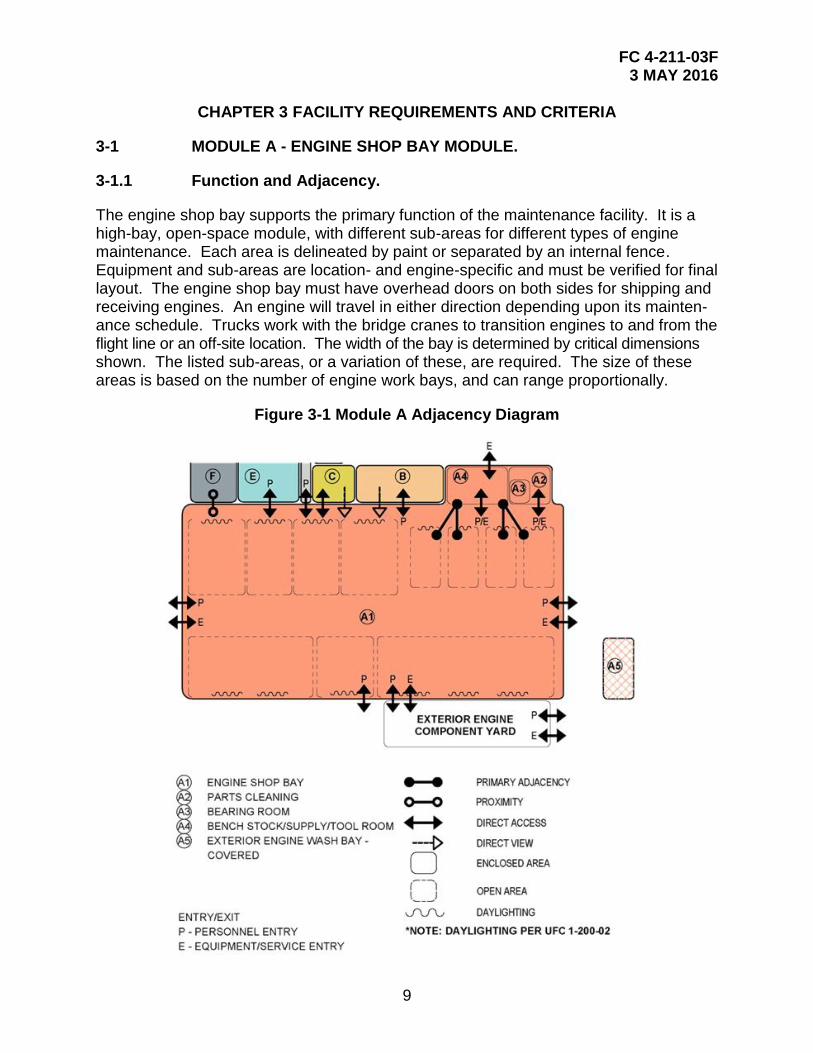
The engine shop bay supports the primary function of the maintenance facility. It is a high-bay, open-space module, with different sub-areas for different types of engine maintenance. Each area is delineated by paint or separated by an internal fence. Equipment and sub-areas are location- and engine-specific and must be verified for final layout. The engine shop bay must have overhead doors on both sides for shipping and receiving engines. An engine will travel in either direction depending upon its mainten-ance schedule. Trucks work with the bridge cranes to transition engines to and from the flight line or an off-site location. The width of the bay is determined by critical dimensions shown. The listed sub-areas, or a variation of these, are required. The size of these areas is based on the number of engine work bays, and can range proportionally.
Figure 3-1 Module A Adjacency Diagram
FC 4-211-03F 3 MAY 2016
10
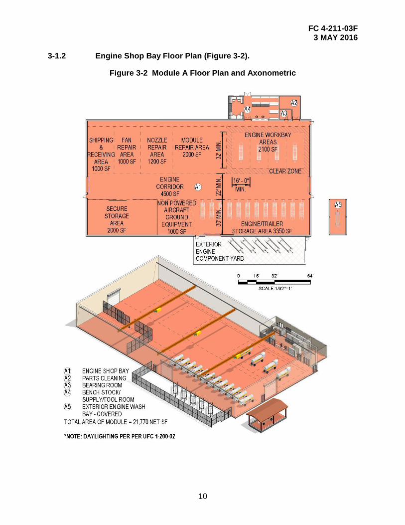
3-1.2 Engine Shop Bay Floor Plan (Figure 3-2).
Figure 3-2 Module A Floor Plan and Axonometric
FC 4-211-03F 3 MAY 2016
11
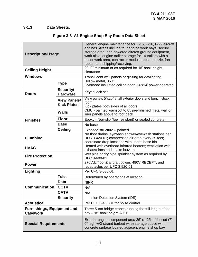
3-1.3 Data Sheets.
Figure 3-3 A1 Engine Shop Bay Room Data Sheet
Description/Usage
General engine maintenance for F-15, F-16, F-22 aircraft engines. Areas include four engine work bays, secure storage area, non-powered aircraft ground equipment, work aisle, engine trailer storage for 14 trailers with a trailer work area, contractor module repair, nozzle, fan repair, and shipping/receiving.
Ceiling Height 20’-0” minimum or as required for 15’ hook height clearance
Windows Translucent wall panels or glazing for daylighting
Doors
Type Hollow metal, 3’x7’ Overhead insulated coiling door, 14’x14’ power operated
Security/ Hardware
Keyed lock set
View Panels/ Kick Plates
View panels 5”x20” at all exterior doors and bench stock room Kick plates both sides of all doors
Finishes
Walls CMU - painted wainscot to 8’, pre-finished metal wall or liner panels above to roof deck
Floor Epoxy - Non-slip (fuel resistant) or sealed concrete
Base No base
Ceiling Exposed structure – painted
Plumbing No floor drains; eyewash shower/eyewash stations per UFC 3-420-01; compressed air drop every 25 feet; coordinate drop locations with users; hose bib
HVAC Heated with overhead infrared heaters; ventilation with exhaust fans and intake louvers
Fire Protection Wet pipe or dry pipe sprinkler system as required by UFC 3-600-01
Power 270Vdc/400hZ aircraft power, 480V RECEPT, and receptacles per UFC 3-520-01
Lighting Per UFC 3-530-01
Communication
Tele. Determined by operations at location
Data NIPR
CCTV N/A
CATV N/A
Security Intrusion Detection System (IDS)
Acoustical Per UFC 3-450-01 for noise control
Furnishings, Equipment and Casework
Three 5-ton bridge cranes running the full length of the bay – 15’ hook height A.F.F.
Special Requirements Exterior engine component area 25’ x 125’ of fenced (7’-0” high w/3-strand barbed wire) storage space with concrete surface located adjacent engine shop bay
FC 4-211-03F 3 MAY 2016
12
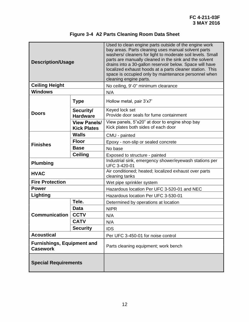
Figure 3-4 A2 Parts Cleaning Room Data Sheet
Description/Usage
Used to clean engine parts outside of the engine work bay areas. Parts cleaning uses manual solvent parts washers/ cleaners for light to moderate soil levels. Small parts are manually cleaned in the sink and the solvent drains into a 30-gallon reservoir below. Space will have localized exhaust hoods at a parts cleaner station. This space is occupied only by maintenance personnel when cleaning engine parts.
Ceiling Height No ceiling, 9'-0" minimum clearance
Windows N/A
Doors
Type Hollow metal, pair 3’x7’
Security/ Hardware
Keyed lock set Provide door seals for fume containment
View Panels/ Kick Plates
View panels, 5”x20” at door to engine shop bay Kick plates both sides of each door
Finishes
Walls CMU - painted
Floor Epoxy - non-slip or sealed concrete
Base No base
Ceiling Exposed to structure - painted
Plumbing Industrial sink, emergency shower/eyewash stations per UFC 3-420-01
HVAC Air conditioned; heated; localized exhaust over parts cleaning tanks
Fire Protection Wet pipe sprinkler system
Power Hazardous location Per UFC 3-520-01 and NEC
Lighting Hazardous location Per UFC 3-530-01
Communication
Tele. Determined by operations at location
Data NIPR
CCTV N/A
CATV N/A
Security IDS
Acoustical Per UFC 3-450-01 for noise control
Furnishings, Equipment and Casework
Parts cleaning equipment; work bench
Special Requirements
FC 4-211-03F 3 MAY 2016
13
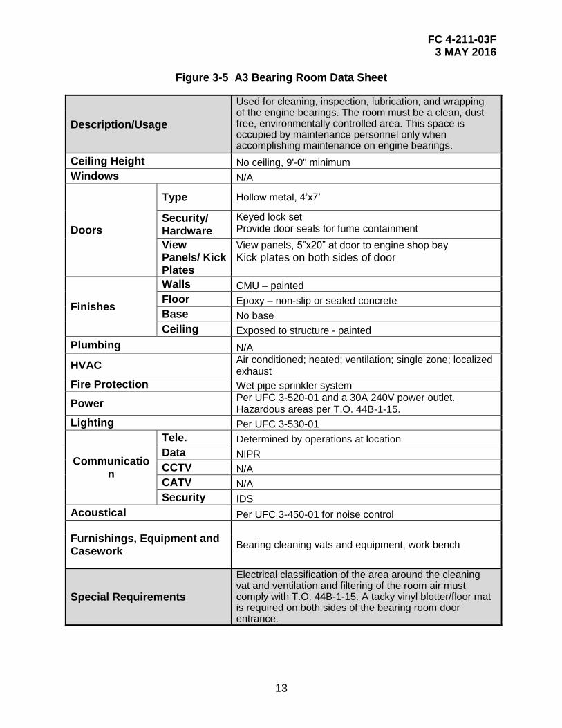
Figure 3-5 A3 Bearing Room Data Sheet
Description/Usage
Used for cleaning, inspection, lubrication, and wrapping of the engine bearings. The room must be a clean, dust free, environmentally controlled area. This space is occupied by maintenance personnel only when accomplishing maintenance on engine bearings.
Ceiling Height No ceiling, 9'-0" minimum
Windows N/A
Doors
Type Hollow metal, 4’x7’
Security/ Hardware
Keyed lock set Provide door seals for fume containment
View Panels/ Kick Plates
View panels, 5”x20” at door to engine shop bay
Kick plates on both sides of door
Finishes
Walls CMU – painted
Floor Epoxy – non-slip or sealed concrete
Base No base
Ceiling Exposed to structure - painted
Plumbing N/A
HVAC Air conditioned; heated; ventilation; single zone; localized exhaust
Fire Protection Wet pipe sprinkler system
Power Per UFC 3-520-01 and a 30A 240V power outlet. Hazardous areas per T.O. 44B-1-15.
Lighting Per UFC 3-530-01
Communication
Tele. Determined by operations at location
Data NIPR
CCTV N/A
CATV N/A
Security IDS
Acoustical Per UFC 3-450-01 for noise control
Furnishings, Equipment and Casework
Bearing cleaning vats and equipment, work bench
Special Requirements
Electrical classification of the area around the cleaning vat and ventilation and filtering of the room air must comply with T.O. 44B-1-15. A tacky vinyl blotter/floor mat is required on both sides of the bearing room door entrance.
FC 4-211-03F 3 MAY 2016
14
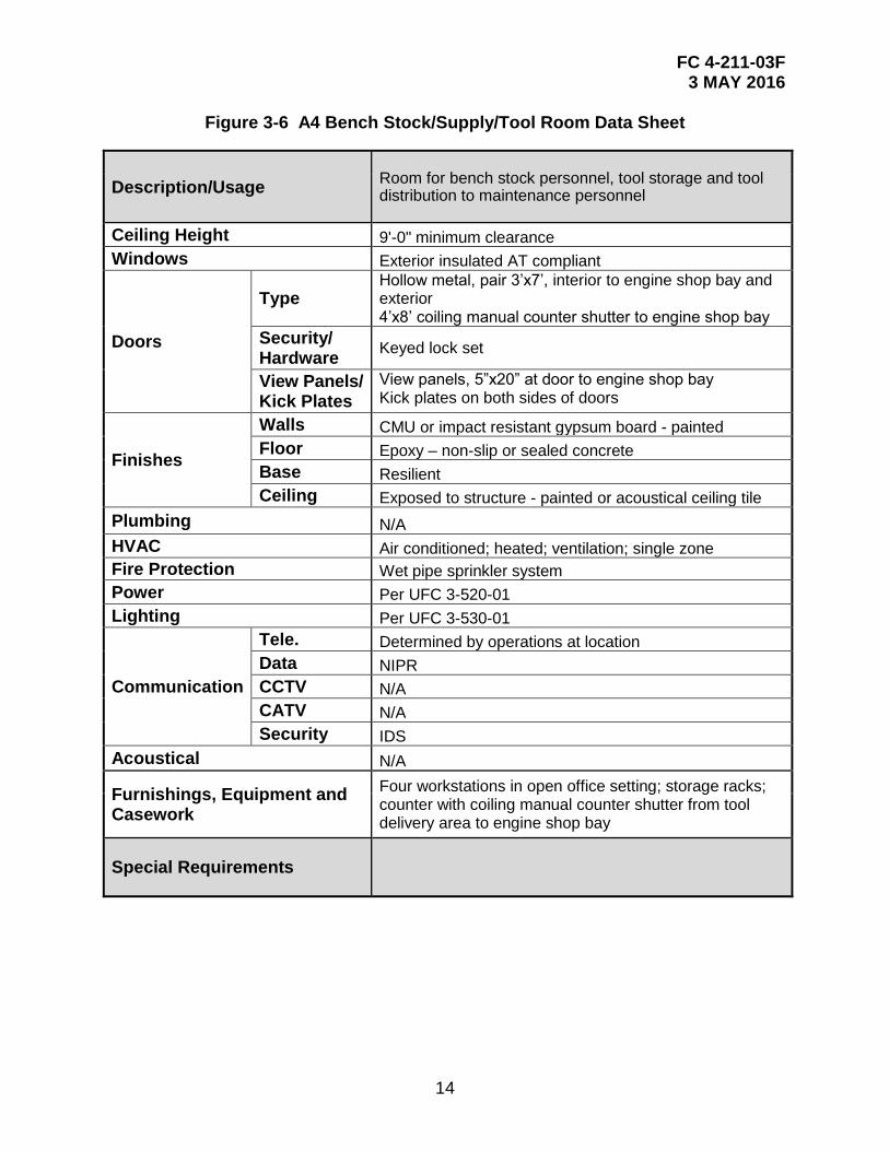
Figure 3-6 A4 Bench Stock/Supply/Tool Room Data Sheet
Description/Usage Room for bench stock personnel, tool storage and tool distribution to maintenance personnel
Ceiling Height 9'-0" minimum clearance
Windows Exterior insulated AT compliant
Doors
Type Hollow metal, pair 3’x7’, interior to engine shop bay and exterior 4’x8’ coiling manual counter shutter to engine shop bay
Security/ Hardware
Keyed lock set
View Panels/ Kick Plates
View panels, 5”x20” at door to engine shop bay Kick plates on both sides of doors
Finishes
Walls CMU or impact resistant gypsum board - painted
Floor Epoxy – non-slip or sealed concrete
Base Resilient
Ceiling Exposed to structure - painted or acoustical ceiling tile
Plumbing N/A
HVAC Air conditioned; heated; ventilation; single zone
Fire Protection Wet pipe sprinkler system
Power Per UFC 3-520-01
Lighting Per UFC 3-530-01
Communication
Tele. Determined by operations at location
Data NIPR
CCTV N/A
CATV N/A
Security IDS
Acoustical N/A
Furnishings, Equipment and Casework
Four workstations in open office setting; storage racks; counter with coiling manual counter shutter from tool delivery area to engine shop bay
Special Requirements
FC 4-211-03F 3 MAY 2016
15
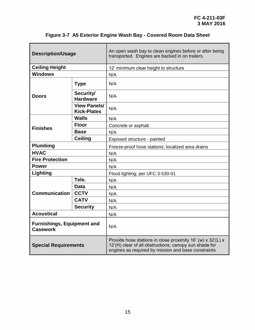
Figure 3-7 A5 Exterior Engine Wash Bay - Covered Room Data Sheet
Description/Usage An open wash bay to clean engines before or after being transported. Engines are backed in on trailers.
Ceiling Height 12’ minimum clear height to structure
Windows N/A
Doors
Type N/A
Security/ Hardware
N/A
View Panels/ Kick-Plates
N/A
Finishes
Walls N/A
Floor Concrete or asphalt
Base N/A
Ceiling Exposed structure - painted
Plumbing Freeze-proof hose stations; localized area drains
HVAC N/A
Fire Protection N/A
Power N/A
Lighting Flood lighting; per UFC 3-530-01
Communication
Tele. N/A
Data N/A
CCTV N/A
CATV N/A
Security N/A
Acoustical N/A
Furnishings, Equipment and Casework
N/A
Special Requirements Provide hose stations in close proximity 16’ (w) x 32’(L) x 12’(H) clear of all obstructions; canopy sun shade for engines as required by mission and base constraints
FC 4-211-03F 3 MAY 2016
16
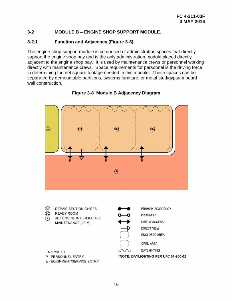
3-2 MODULE B – ENGINE SHOP SUPPORT MODULE.
3-2.1 Function and Adjacency (Figure 3-8).
The engine shop support module is comprised of administration spaces that directly support the engine shop bay and is the only administration module placed directly adjacent to the engine shop bay. It is used by maintenance crews or personnel working directly with maintenance crews. Space requirements for personnel is the driving force in determining the net square footage needed in this module. These spaces can be separated by demountable partitions, systems furniture, or metal stud/gypsum board wall construction.
Figure 3-8 Module B Adjacency Diagram
FC 4-211-03F 3 MAY 2016
17
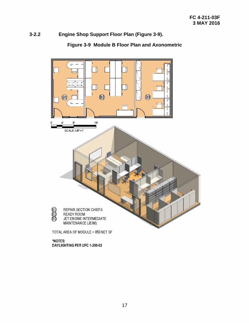
3-2.2 Engine Shop Support Floor Plan (Figure 3-9).
Figure 3-9 Module B Floor Plan and Axonometric
FC 4-211-03F 3 MAY 2016
18
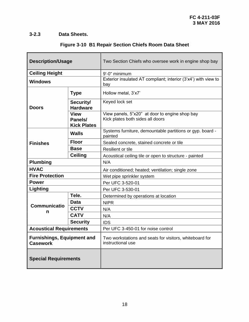
3-2.3 Data Sheets.
Figure 3-10 B1 Repair Section Chiefs Room Data Sheet
Description/Usage Two Section Chiefs who oversee work in engine shop bay
Ceiling Height 9'-0" minimum
Windows Exterior insulated AT compliant; interior (3’x4’) with view to bay
Doors
Type Hollow metal, 3’x7’
Security/ Hardware
Keyed lock set
View Panels/ Kick Plates
View panels, 5”x20” at door to engine shop bay Kick plates both sides all doors
Finishes
Walls Systems furniture, demountable partitions or gyp. board -painted
Floor Sealed concrete, stained concrete or tile
Base Resilient or tile
Ceiling Acoustical ceiling tile or open to structure - painted
Plumbing N/A
HVAC Air conditioned; heated; ventilation; single zone
Fire Protection Wet pipe sprinkler system
Power Per UFC 3-520-01
Lighting Per UFC 3-530-01
Communication
Tele. Determined by operations at location
Data NIPR
CCTV N/A
CATV N/A
Security IDS
Acoustical Requirements Per UFC 3-450-01 for noise control
Furnishings, Equipment and Casework
Two workstations and seats for visitors, whiteboard for instructional use
Special Requirements
FC 4-211-03F 3 MAY 2016
19
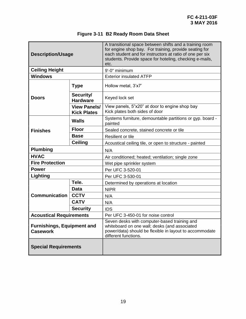
Figure 3-11 B2 Ready Room Data Sheet
Description/Usage
A transitional space between shifts and a training room for engine shop bay. For training, provide seating for each student and for instructors at ratio of one per six students. Provide space for hoteling, checking e-mails, etc.
Ceiling Height 9'-0" minimum
Windows Exterior insulated ATFP
Doors
Type Hollow metal, 3’x7’
Security/ Hardware
Keyed lock set
View Panels/ Kick Plates
View panels, 5”x20” at door to engine shop bay Kick plates both sides of door
Finishes
Walls Systems furniture, demountable partitions or gyp. board - painted
Floor Sealed concrete, stained concrete or tile
Base Resilient or tile
Ceiling Acoustical ceiling tile, or open to structure - painted
Plumbing N/A
HVAC Air conditioned; heated; ventilation; single zone
Fire Protection Wet pipe sprinkler system
Power Per UFC 3-520-01
Lighting Per UFC 3-530-01
Communication
Tele. Determined by operations at location
Data NIPR
CCTV N/A
CATV N/A
Security IDS
Acoustical Requirements Per UFC 3-450-01 for noise control
Furnishings, Equipment and Casework
Seven desks with computer-based training and whiteboard on one wall; desks (and associated power/data) should be flexible in layout to accommodate different functions.
Special Requirements
FC 4-211-03F 3 MAY 2016
20
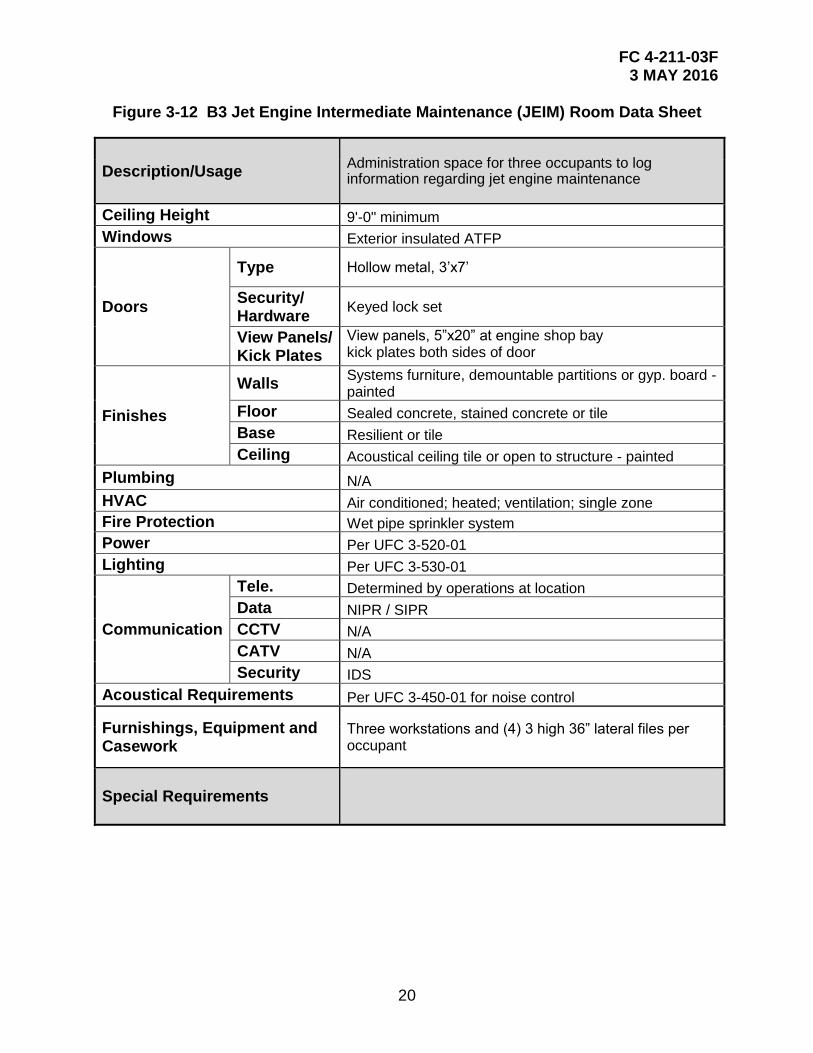
Figure 3-12 B3 Jet Engine Intermediate Maintenance (JEIM) Room Data Sheet
Description/Usage Administration space for three occupants to log information regarding jet engine maintenance
Ceiling Height 9'-0" minimum
Windows Exterior insulated ATFP
Doors
Type Hollow metal, 3’x7’
Security/ Hardware
Keyed lock set
View Panels/ Kick Plates
View panels, 5”x20” at engine shop bay kick plates both sides of door
Finishes
Walls Systems furniture, demountable partitions or gyp. board - painted
Floor Sealed concrete, stained concrete or tile
Base Resilient or tile
Ceiling Acoustical ceiling tile or open to structure - painted
Plumbing N/A
HVAC Air conditioned; heated; ventilation; single zone
Fire Protection Wet pipe sprinkler system
Power Per UFC 3-520-01
Lighting Per UFC 3-530-01
Communication
Tele. Determined by operations at location
Data NIPR / SIPR
CCTV N/A
CATV N/A
Security IDS
Acoustical Requirements Per UFC 3-450-01 for noise control
Furnishings, Equipment and Casework
Three workstations and (4) 3 high 36” lateral files per occupant
Special Requirements
FC 4-211-03F 3 MAY 2016
21
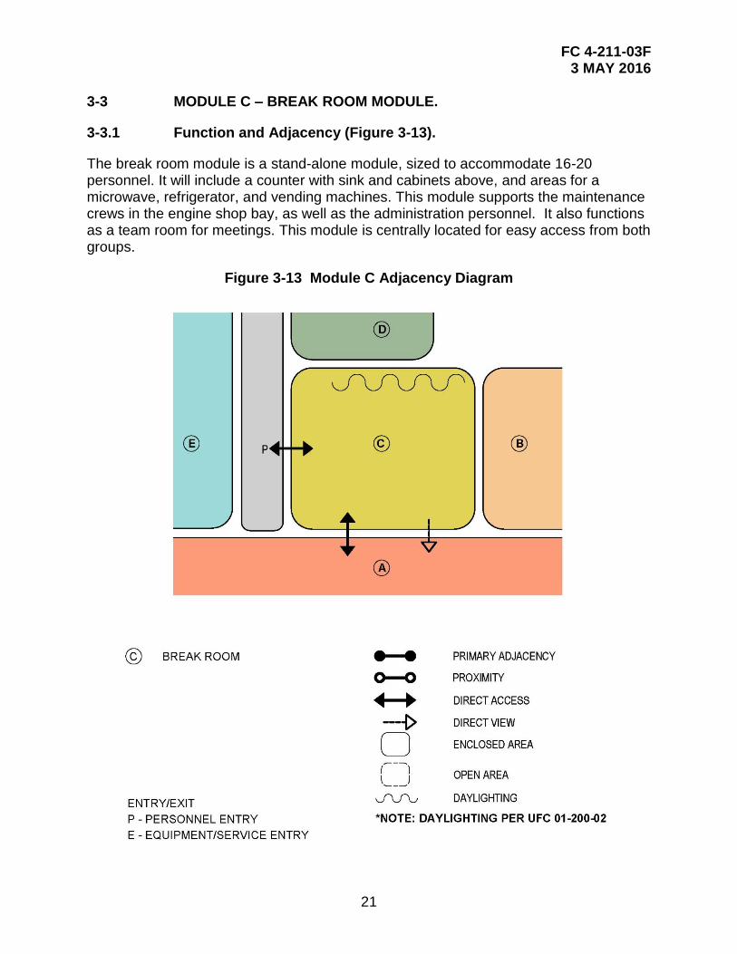
3-3 MODULE C – BREAK ROOM MODULE.
3-3.1 Function and Adjacency (Figure 3-13).
The break room module is a stand-alone module, sized to accommodate 16-20 personnel. It will include a counter with sink and cabinets above, and areas for a microwave, refrigerator, and vending machines. This module supports the maintenance crews in the engine shop bay, as well as the administration personnel. It also functions as a team room for meetings. This module is centrally located for easy access from both groups.
Figure 3-13 Module C Adjacency Diagram
FC 4-211-03F 3 MAY 2016
22
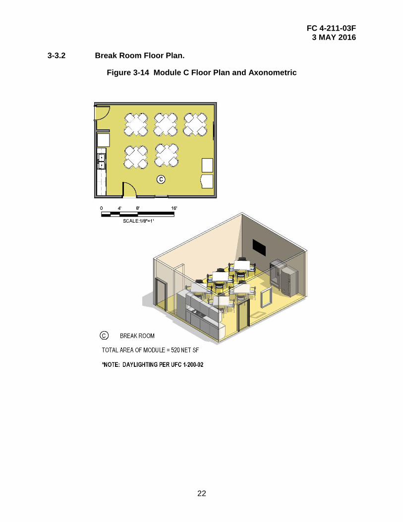
3-3.2 Break Room Floor Plan.
Figure 3-14 Module C Floor Plan and Axonometric
C
C C
FC 4-211-03F 3 MAY 2016
23
3-3.3 Data Sheets.
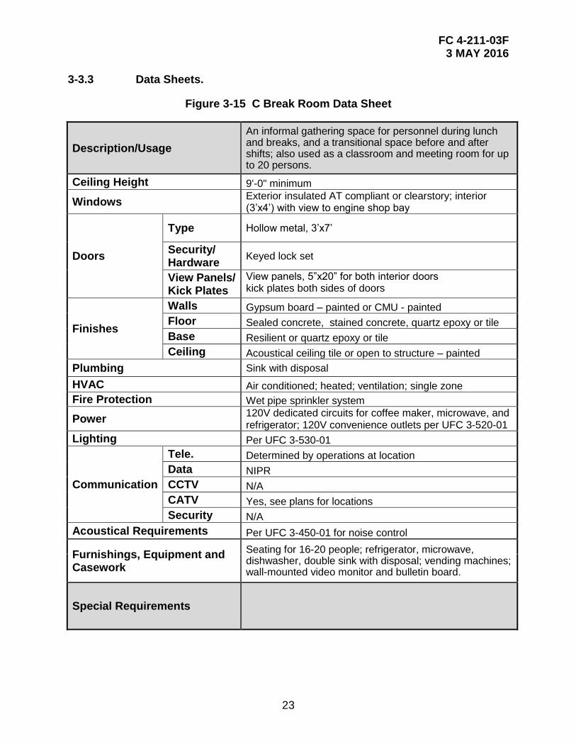
Figure 3-15 C Break Room Data Sheet
Description/Usage
An informal gathering space for personnel during lunch and breaks, and a transitional space before and after shifts; also used as a classroom and meeting room for up to 20 persons.
Ceiling Height 9'-0" minimum
Windows Exterior insulated AT compliant or clearstory; interior (3’x4’) with view to engine shop bay
Doors
Type Hollow metal, 3’x7’
Security/ Hardware
Keyed lock set
View Panels/ Kick Plates
View panels, 5”x20” for both interior doors kick plates both sides of doors
Finishes
Walls Gypsum board – painted or CMU - painted
Floor Sealed concrete, stained concrete, quartz epoxy or tile
Base Resilient or quartz epoxy or tile
Ceiling Acoustical ceiling tile or open to structure – painted
Plumbing Sink with disposal
HVAC Air conditioned; heated; ventilation; single zone
Fire Protection Wet pipe sprinkler system
Power 120V dedicated circuits for coffee maker, microwave, and refrigerator; 120V convenience outlets per UFC 3-520-01
Lighting Per UFC 3-530-01
Communication
Tele. Determined by operations at location
Data NIPR
CCTV N/A
CATV Yes, see plans for locations
Security N/A
Acoustical Requirements Per UFC 3-450-01 for noise control
Furnishings, Equipment and Casework
Seating for 16-20 people; refrigerator, microwave, dishwasher, double sink with disposal; vending machines; wall-mounted video monitor and bulletin board.
Special Requirements
FC 4-211-03F 3 MAY 2016
24
3-4 MODULE D – FLIGHT CHIEF/TRAINING ADMINISTRATION MODULE.
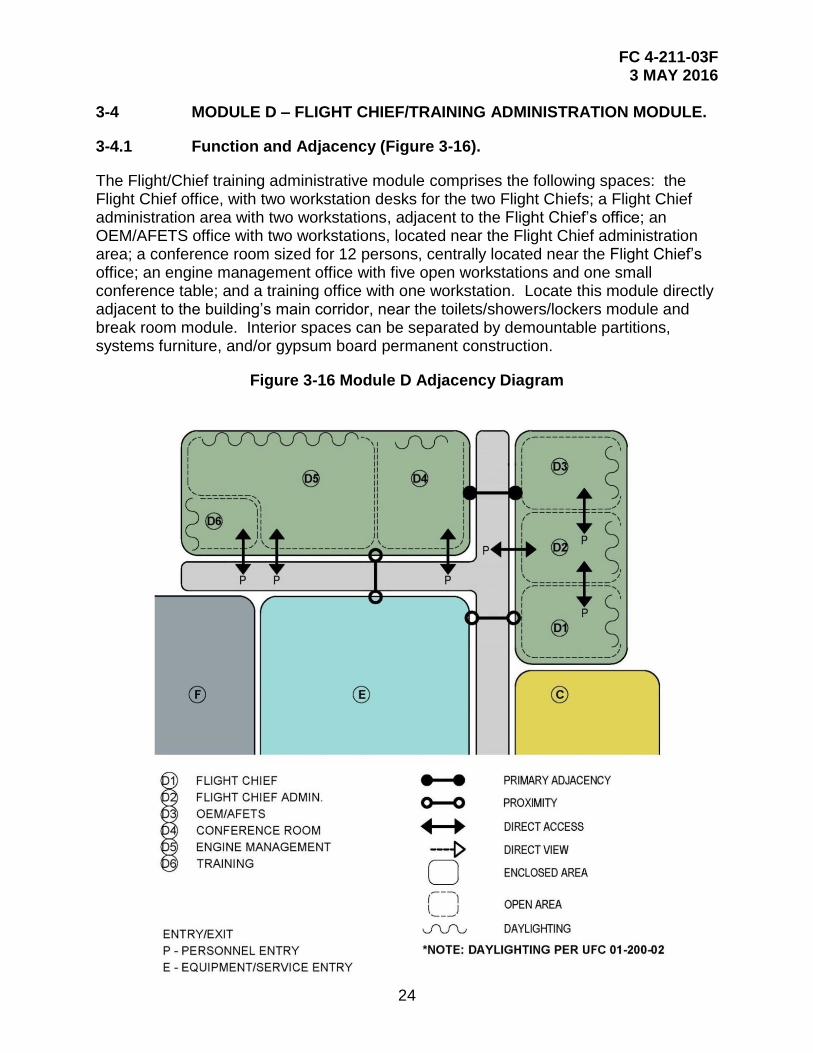
3-4.1 Function and Adjacency (Figure 3-16).
The Flight/Chief training administrative module comprises the following spaces: the Flight Chief office, with two workstation desks for the two Flight Chiefs; a Flight Chief administration area with two workstations, adjacent to the Flight Chief’s office; an OEM/AFETS office with two workstations, located near the Flight Chief administration area; a conference room sized for 12 persons, centrally located near the Flight Chief’s office; an engine management office with five open workstations and one small conference table; and a training office with one workstation. Locate this module directly adjacent to the building’s main corridor, near the toilets/showers/lockers module and break room module. Interior spaces can be separated by demountable partitions, systems furniture, and/or gypsum board permanent construction.
Figure 3-16 Module D Adjacency Diagram
FC 4-211-03F 3 MAY 2016
25
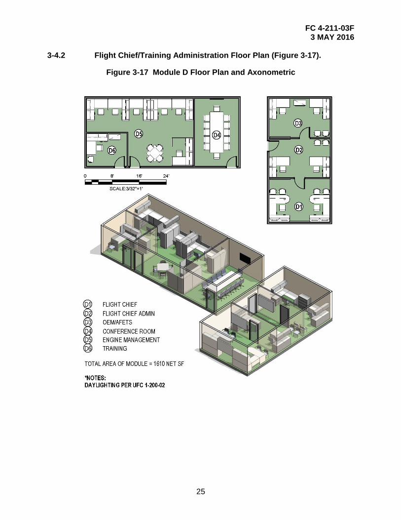
3-4.2 Flight Chief/Training Administration Floor Plan (Figure 3-17).
Figure 3-17 Module D Floor Plan and Axonometric
FC 4-211-03F 3 MAY 2016
26
3-4.3 Data Sheets.
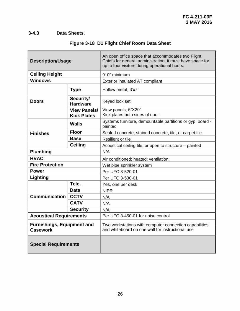
Figure 3-18 D1 Flight Chief Room Data Sheet
Description/Usage An open office space that accommodates two Flight Chiefs for general administration, it must have space for up to four visitors during operational hours.
Ceiling Height 9'-0" minimum
Windows Exterior insulated AT compliant
Doors
Type Hollow metal, 3’x7’
Security/ Hardware
Keyed lock set
View Panels/ Kick Plates
View panels, 5”X20” Kick plates both sides of door
Finishes
Walls Systems furniture, demountable partitions or gyp. board -painted
Floor Sealed concrete, stained concrete, tile, or carpet tile
Base Resilient or tile
Ceiling Acoustical ceiling tile, or open to structure – painted
Plumbing N/A
HVAC Air conditioned; heated; ventilation;
Fire Protection Wet pipe sprinkler system
Power Per UFC 3-520-01
Lighting Per UFC 3-530-01
Communication
Tele. Yes, one per desk
Data NIPR
CCTV N/A
CATV N/A
Security N/A
Acoustical Requirements Per UFC 3-450-01 for noise control
Furnishings, Equipment and Casework
Two workstations with computer connection capabilities and whiteboard on one wall for instructional use
Special Requirements
FC 4-211-03F 3 MAY 2016
27
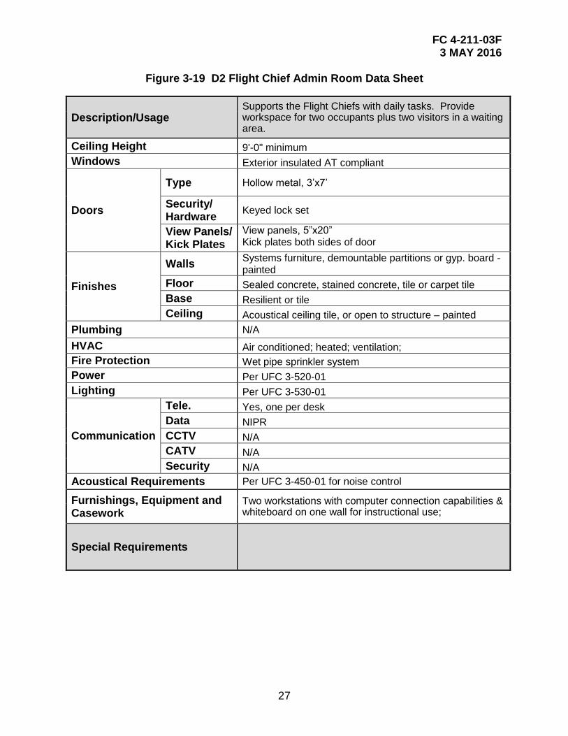
Figure 3-19 D2 Flight Chief Admin Room Data Sheet
Description/Usage Supports the Flight Chiefs with daily tasks. Provide workspace for two occupants plus two visitors in a waiting area.
Ceiling Height 9'-0" minimum
Windows Exterior insulated AT compliant
Doors
Type Hollow metal, 3’x7’
Security/ Hardware
Keyed lock set
View Panels/ Kick Plates
View panels, 5”x20” Kick plates both sides of door
Finishes
Walls Systems furniture, demountable partitions or gyp. board -painted
Floor Sealed concrete, stained concrete, tile or carpet tile
Base Resilient or tile
Ceiling Acoustical ceiling tile, or open to structure – painted
Plumbing N/A
HVAC Air conditioned; heated; ventilation;
Fire Protection Wet pipe sprinkler system
Power Per UFC 3-520-01
Lighting Per UFC 3-530-01
Communication
Tele. Yes, one per desk
Data NIPR
CCTV N/A
CATV N/A
Security N/A
Acoustical Requirements Per UFC 3-450-01 for noise control
Furnishings, Equipment and Casework
Two workstations with computer connection capabilities & whiteboard on one wall for instructional use;
Special Requirements
FC 4-211-03F 3 MAY 2016
28
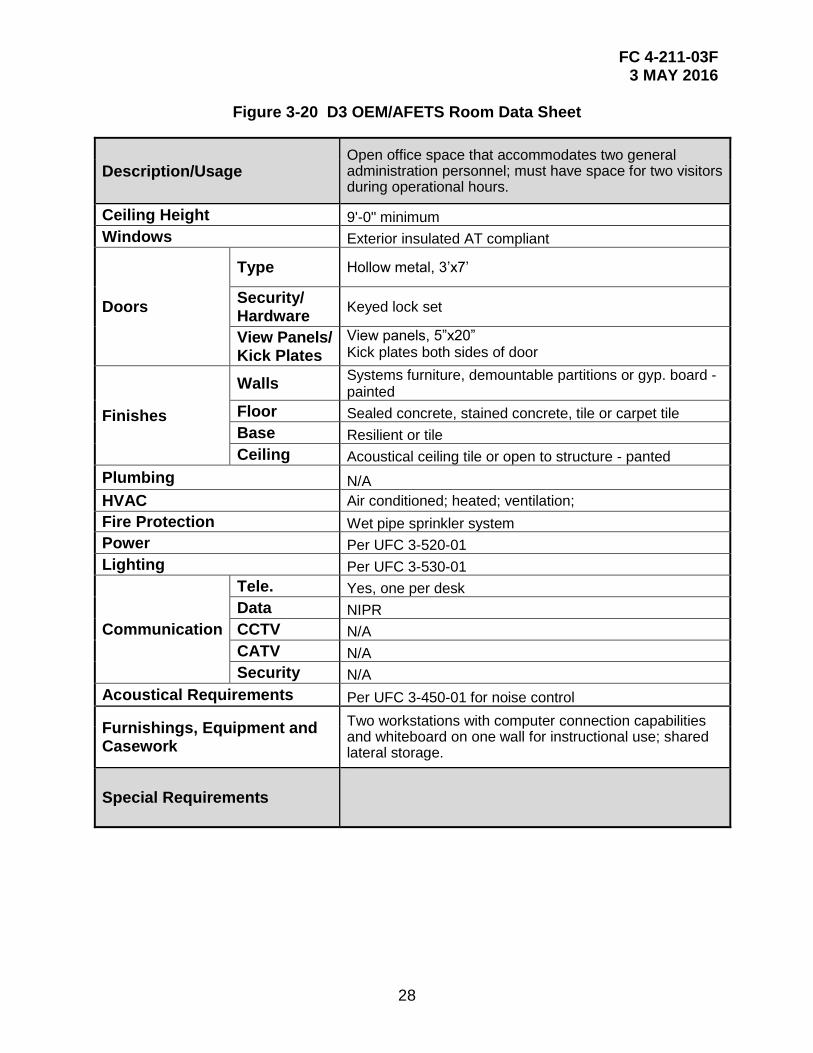
Figure 3-20 D3 OEM/AFETS Room Data Sheet
Description/Usage Open office space that accommodates two general administration personnel; must have space for two visitors during operational hours.
Ceiling Height 9'-0" minimum
Windows Exterior insulated AT compliant
Doors
Type Hollow metal, 3’x7’
Security/ Hardware
Keyed lock set
View Panels/ Kick Plates
View panels, 5”x20” Kick plates both sides of door
Finishes
Walls Systems furniture, demountable partitions or gyp. board -painted
Floor Sealed concrete, stained concrete, tile or carpet tile
Base Resilient or tile
Ceiling Acoustical ceiling tile or open to structure - panted
Plumbing N/A
HVAC Air conditioned; heated; ventilation;
Fire Protection Wet pipe sprinkler system
Power Per UFC 3-520-01
Lighting Per UFC 3-530-01
Communication
Tele. Yes, one per desk
Data NIPR
CCTV N/A
CATV N/A
Security N/A
Acoustical Requirements Per UFC 3-450-01 for noise control
Furnishings, Equipment and Casework
Two workstations with computer connection capabilities and whiteboard on one wall for instructional use; shared lateral storage.
Special Requirements
FC 4-211-03F 3 MAY 2016
29
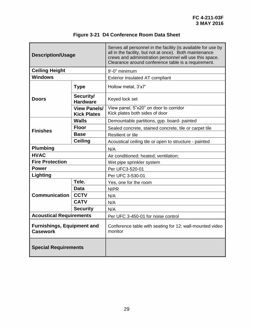
Figure 3-21 D4 Conference Room Data Sheet
Description/Usage
Serves all personnel in the facility (is available for use by all in the facility, but not at once). Both maintenance crews and administration personnel will use this space. Clearance around conference table is a requirement.
Ceiling Height 9'-0" minimum
Windows Exterior insulated AT compliant
Doors
Type Hollow metal, 3’x7’
Security/ Hardware
Keyed lock set
View Panels/ Kick Plates
View panel, 5”x20” on door to corridor Kick plates both sides of door
Finishes
Walls Demountable partitions, gyp. board- painted
Floor Sealed concrete, stained concrete, tile or carpet tile
Base Resilient or tile
Ceiling Acoustical ceiling tile or open to structure - painted
Plumbing N/A
HVAC Air conditioned; heated; ventilation;
Fire Protection Wet pipe sprinkler system
Power Per UFC3-520-01
Lighting Per UFC 3-530-01
Communication
Tele. Yes, one for the room
Data NIPR
CCTV N/A
CATV N/A
Security N/A
Acoustical Requirements Per UFC 3-450-01 for noise control
Furnishings, Equipment and Casework
Conference table with seating for 12; wall-mounted video monitor
Special Requirements
FC 4-211-03F 3 MAY 2016
30
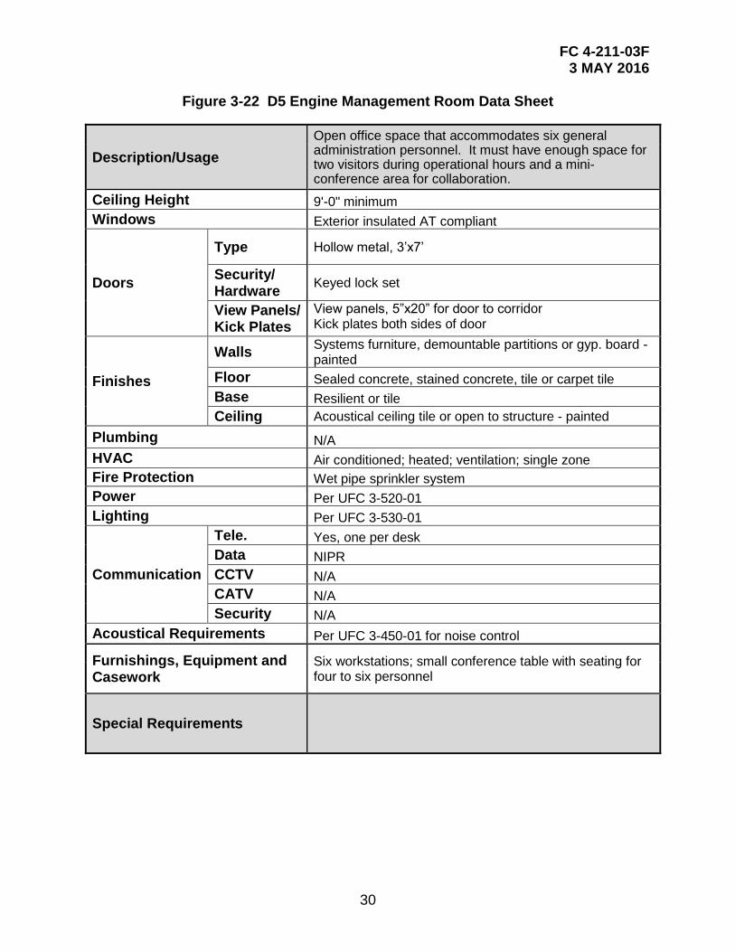
Figure 3-22 D5 Engine Management Room Data Sheet
Description/Usage
Open office space that accommodates six general administration personnel. It must have enough space for two visitors during operational hours and a mini-conference area for collaboration.
Ceiling Height 9'-0" minimum
Windows Exterior insulated AT compliant
Doors
Type Hollow metal, 3’x7’
Security/ Hardware
Keyed lock set
View Panels/ Kick Plates
View panels, 5”x20” for door to corridor Kick plates both sides of door
Finishes
Walls Systems furniture, demountable partitions or gyp. board -painted
Floor Sealed concrete, stained concrete, tile or carpet tile
Base Resilient or tile
Ceiling Acoustical ceiling tile or open to structure - painted
Plumbing N/A
HVAC Air conditioned; heated; ventilation; single zone
Fire Protection Wet pipe sprinkler system
Power Per UFC 3-520-01
Lighting Per UFC 3-530-01
Communication
Tele. Yes, one per desk
Data NIPR
CCTV N/A
CATV N/A
Security N/A
Acoustical Requirements Per UFC 3-450-01 for noise control
Furnishings, Equipment and Casework
Six workstations; small conference table with seating for four to six personnel
Special Requirements
FC 4-211-03F 3 MAY 2016
31
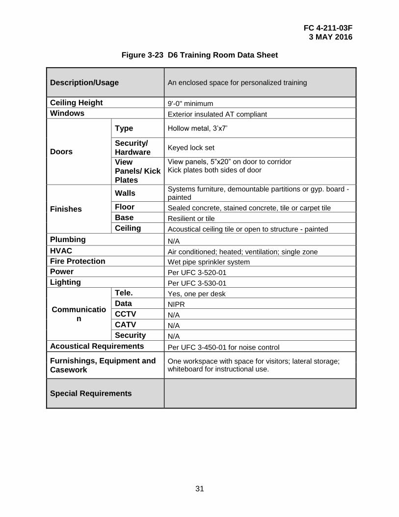
Figure 3-23 D6 Training Room Data Sheet
Description/Usage An enclosed space for personalized training
Ceiling Height 9'-0" minimum
Windows Exterior insulated AT compliant
Doors
Type Hollow metal, 3’x7’
Security/ Hardware
Keyed lock set
View Panels/ Kick Plates
View panels, 5”x20” on door to corridor Kick plates both sides of door
Finishes
Walls Systems furniture, demountable partitions or gyp. board -painted
Floor Sealed concrete, stained concrete, tile or carpet tile
Base Resilient or tile
Ceiling Acoustical ceiling tile or open to structure - painted
Plumbing N/A
HVAC Air conditioned; heated; ventilation; single zone
Fire Protection Wet pipe sprinkler system
Power Per UFC 3-520-01
Lighting Per UFC 3-530-01
Communication
Tele. Yes, one per desk
Data NIPR
CCTV N/A
CATV N/A
Security N/A
Acoustical Requirements Per UFC 3-450-01 for noise control
Furnishings, Equipment and Casework
One workspace with space for visitors; lateral storage; whiteboard for instructional use.
Special Requirements
FC 4-211-03F 3 MAY 2016
32
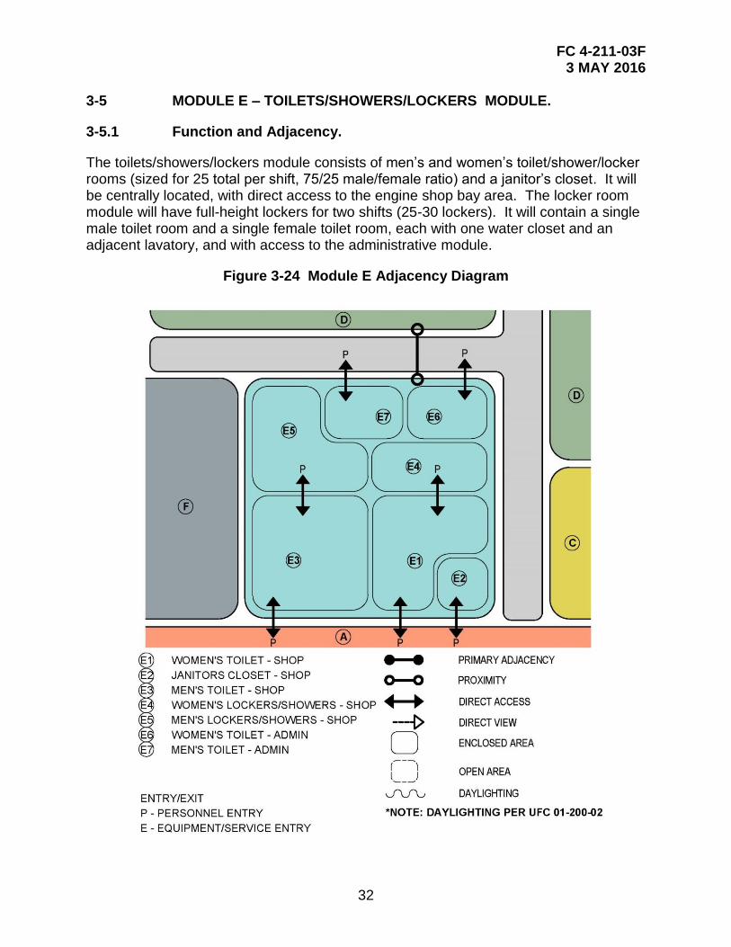
3-5 MODULE E – TOILETS/SHOWERS/LOCKERS MODULE.
3-5.1 Function and Adjacency.
The toilets/showers/lockers module consists of men’s and women’s toilet/shower/locker rooms (sized for 25 total per shift, 75/25 male/female ratio) and a janitor’s closet. It will be centrally located, with direct access to the engine shop bay area. The locker room module will have full-height lockers for two shifts (25-30 lockers). It will contain a single male toilet room and a single female toilet room, each with one water closet and an adjacent lavatory, and with access to the administrative module.
Figure 3-24 Module E Adjacency Diagram
FC 4-211-03F 3 MAY 2016
33
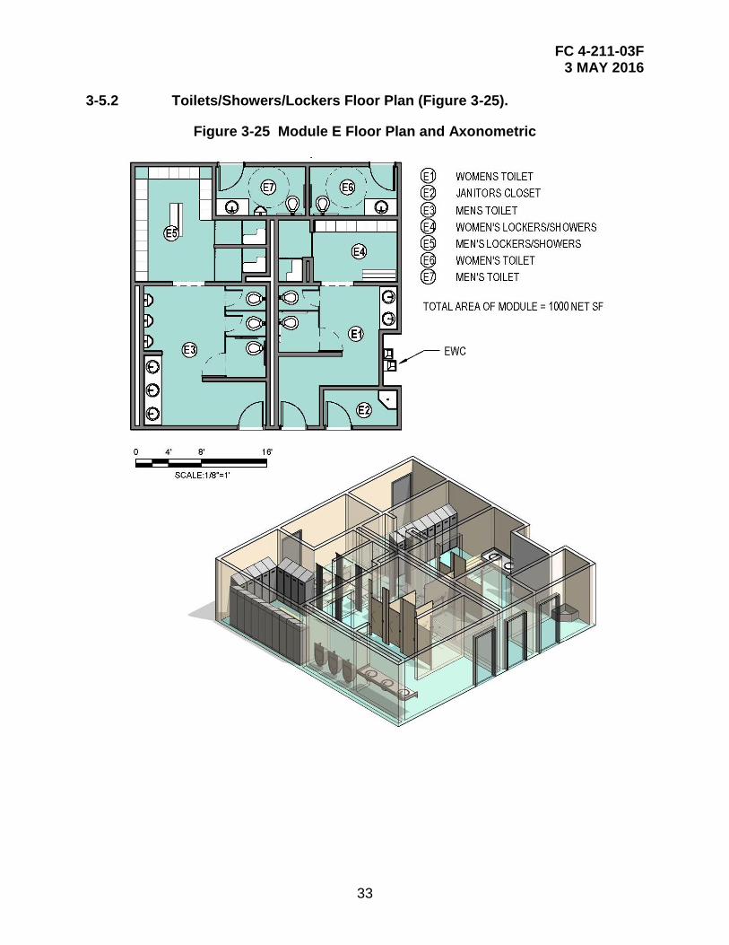
3-5.2 Toilets/Showers/Lockers Floor Plan (Figure 3-25).
Figure 3-25 Module E Floor Plan and Axonometric
FC 4-211-03F 3 MAY 2016
34
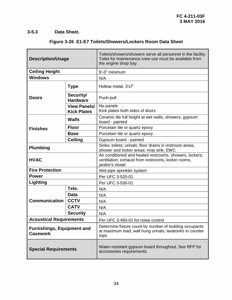
3-5.3 Data Sheet.
Figure 3-26 E1-E7 Toilets/Showers/Lockers Room Data Sheet
Description/Usage Toilets/showers/showers serve all personnel in the facility. Toilet for maintenance crew use must be available from the engine shop bay.
Ceiling Height 9’-0” minimum
Windows N/A
Doors
Type Hollow metal, 3’x7’
Security/ Hardware
Push-pull
View Panels/ Kick Plates
No panels Kick plates both sides of doors
Finishes
Walls Ceramic tile full height at wet walls, showers, gypsum board - painted
Floor Porcelain tile or quartz epoxy
Base Porcelain tile or quartz epoxy
Ceiling Gypsum board - painted
Plumbing Sinks; toilets; urinals; floor drains in restroom areas, shower and locker areas; mop sink; EWC
HVAC Air conditioned and heated restrooms, showers, lockers; ventilation; exhaust from restrooms, locker rooms, janitor’s closet
Fire Protection Wet pipe sprinkler system
Power Per UFC 3-520-01
Lighting Per UFC 3-530-01
Communication
Tele. N/A
Data N/A
CCTV N/A
CATV N/A
Security N/A
Acoustical Requirements Per UFC 3-450-01 for noise control
Furnishings, Equipment and Casework
Determine fixture count by number of building occupants at maximum load; wall hung urinals; lavatories in counter tops.
Special Requirements Water-resistant gypsum board throughout. See RFP for accessories requirements.
FC 4-211-03F 3 MAY 2016
35
3-6 MODULE F – BUILDING SUPPORT MODULE.
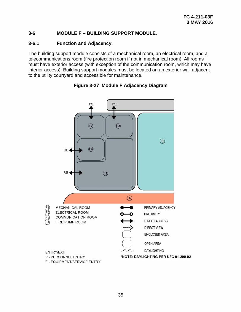
3-6.1 Function and Adjacency.
The building support module consists of a mechanical room, an electrical room, and a telecommunications room (fire protection room if not in mechanical room). All rooms must have exterior access (with exception of the communication room, which may have interior access). Building support modules must be located on an exterior wall adjacent to the utility courtyard and accessible for maintenance.
Figure 3-27 Module F Adjacency Diagram
FC 4-211-03F 3 MAY 2016
36
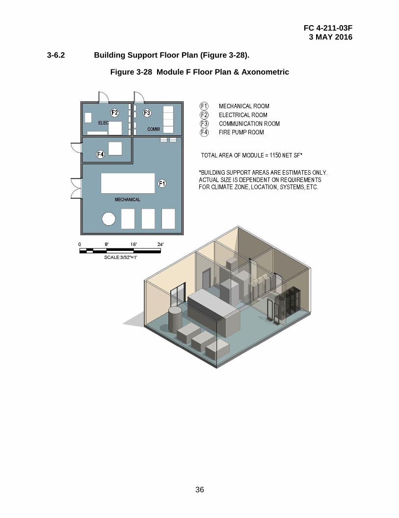
3-6.2 Building Support Floor Plan (Figure 3-28).
Figure 3-28 Module F Floor Plan & Axonometric
FC 4-211-03F 3 MAY 2016
37
3-6.3 Data Sheets.
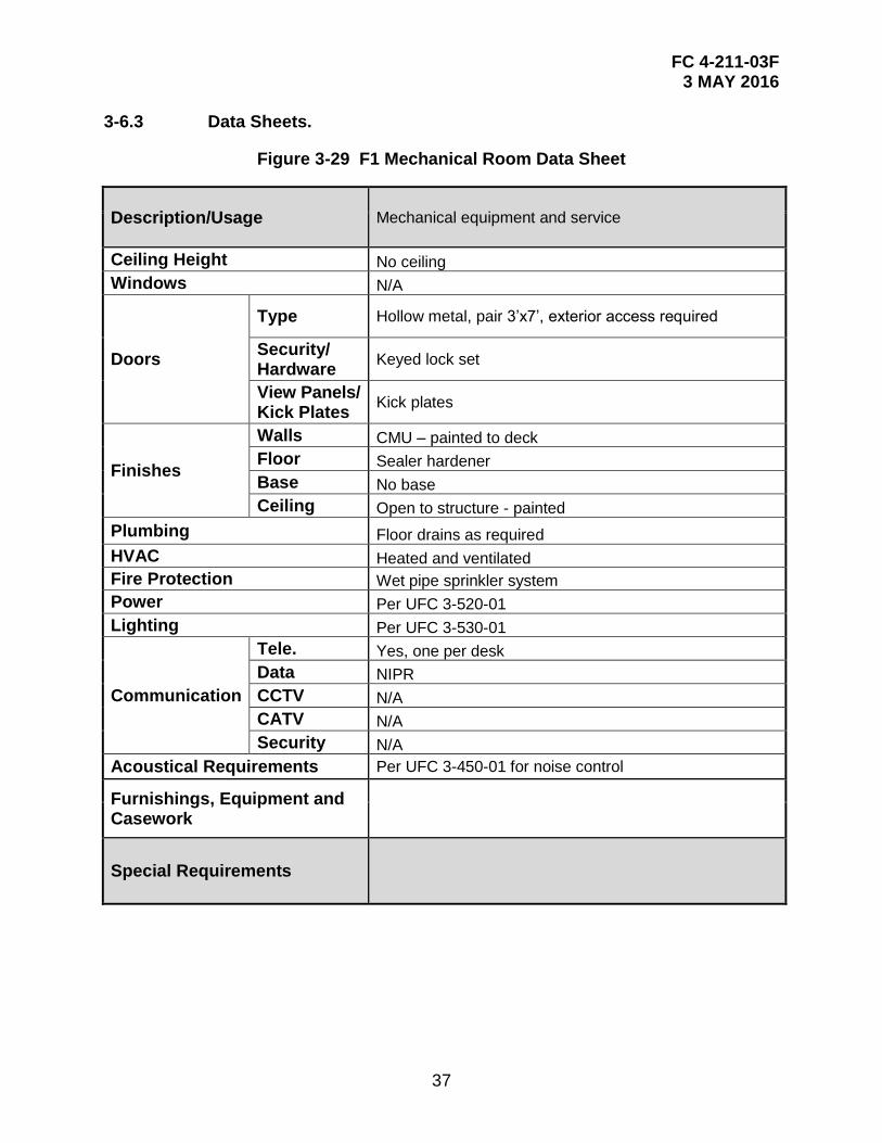
Figure 3-29 F1 Mechanical Room Data Sheet
Description/Usage Mechanical equipment and service
Ceiling Height No ceiling
Windows N/A
Doors
Type Hollow metal, pair 3’x7’, exterior access required
Security/ Hardware
Keyed lock set
View Panels/ Kick Plates
Kick plates
Finishes
Walls CMU – painted to deck
Floor Sealer hardener
Base No base
Ceiling Open to structure - painted
Plumbing Floor drains as required
HVAC Heated and ventilated
Fire Protection Wet pipe sprinkler system
Power Per UFC 3-520-01
Lighting Per UFC 3-530-01
Communication
Tele. Yes, one per desk
Data NIPR
CCTV N/A
CATV N/A
Security N/A
Acoustical Requirements Per UFC 3-450-01 for noise control
Furnishings, Equipment and Casework
Special Requirements

FC 4-211-03F 3 MAY 2016
38
Figure 3-30 F2 Electrical Room Data Sheet
Description/Usage Electrical equipment and service
Ceiling Height No ceiling
Windows N/A
Doors
Type Hollow metal, 3’x7’, exterior access required
Security/ Hardware
Keyed lock set
View Panels/ Kick Plates
Kick plates
Finishes
Walls CMU - painted
Floor Sealer hardener
Base No base
Ceiling Open to structure - painted
Plumbing N/A
HVAC Heated and ventilated
Fire Protection Wet pipe sprinkler system
Power Per UFC 3-520-01
Lighting Per UFC 3-530-01
Communication
Tele. One per desk
Data NIPR
CCTV N/A
CATV N/A
Security N/AB
Acoustical Requirements N/A
Furnishings, Equipment and Casework
Special Requirements

FC 4-211-03F 3 MAY 2016
39
Figure 3-31 F3 Communication Room Data Sheet
Description/Usage Communication and UPS service
Ceiling Height 9'-0" minimum clearance
Windows N/A
Doors
Type Hollow metal, 3’x7’, interior or exterior access is acceptable
Security/ Hardware
Keyed lock set
View Panels/ Kick Plates
Kick plates
Finishes
Walls CMU - painted
Floor Sealer hardener
Base No base
Ceiling Open to structure - painted
Plumbing N/A
HVAC Heated and ventilated; dedicated cooling for comm.
Fire Protection Wet pipe sprinkler system
Power Per UFC 3-520-01
Lighting Per UFC 3-530-01
Communication
Tele. Yes, one per desk
Data NIPR
CCTV N/A
CATV N/A
Security N/A
Acoustical Requirements N/A
Furnishings, Equipment and Casework
Special Requirements
FC 4-211-03F 3 MAY 2016
40
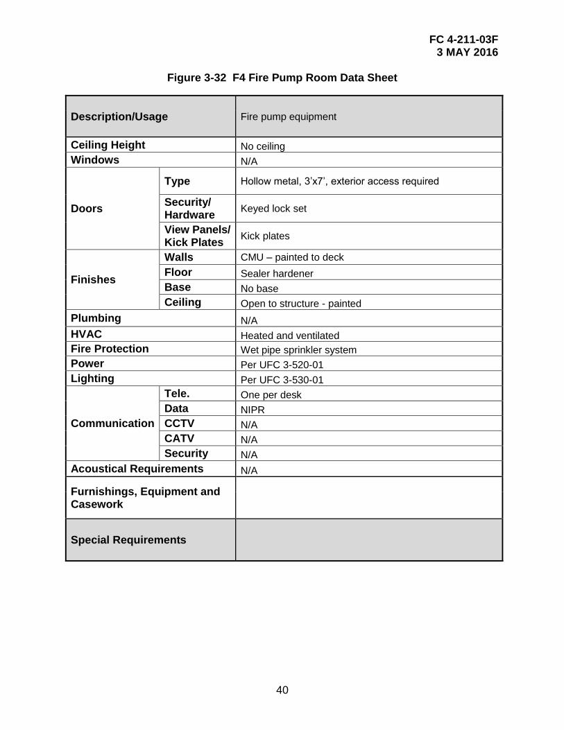
Figure 3-32 F4 Fire Pump Room Data Sheet
Description/Usage Fire pump equipment
Ceiling Height No ceiling
Windows N/A
Doors
Type Hollow metal, 3’x7’, exterior access required
Security/ Hardware
Keyed lock set
View Panels/ Kick Plates
Kick plates
Finishes
Walls CMU – painted to deck
Floor Sealer hardener
Base No base
Ceiling Open to structure - painted
Plumbing N/A
HVAC Heated and ventilated
Fire Protection Wet pipe sprinkler system
Power Per UFC 3-520-01
Lighting Per UFC 3-530-01
Communication
Tele. One per desk
Data NIPR
CCTV N/A
CATV N/A
Security N/A
Acoustical Requirements N/A
Furnishings, Equipment and Casework
Special Requirements
FC 4-211-03F 3 MAY 2016
41
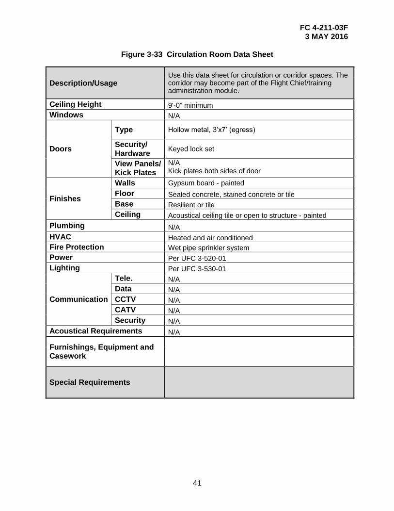
Figure 3-33 Circulation Room Data Sheet
Description/Usage Use this data sheet for circulation or corridor spaces. The corridor may become part of the Flight Chief/training administration module.
Ceiling Height 9'-0" minimum
Windows N/A
Doors
Type Hollow metal, 3’x7’ (egress)
Security/ Hardware
Keyed lock set
View Panels/ Kick Plates
N/A Kick plates both sides of door
Finishes
Walls Gypsum board - painted
Floor Sealed concrete, stained concrete or tile
Base Resilient or tile
Ceiling Acoustical ceiling tile or open to structure - painted
Plumbing N/A
HVAC Heated and air conditioned
Fire Protection Wet pipe sprinkler system
Power Per UFC 3-520-01
Lighting Per UFC 3-530-01
Communication
Tele. N/A
Data N/A
CCTV N/A
CATV N/A
Security N/A
Acoustical Requirements N/A
Furnishings, Equipment and Casework
Special Requirements

FC 4-211-03F 3 MAY 2016
42
This Page Intentionally Left Blank
FC 4-211-03F 3 MAY 2016
43
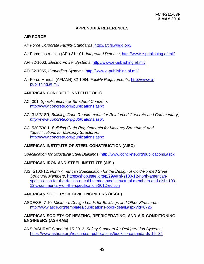
APPENDIX A REFERENCES
AIR FORCE
Air Force Corporate Facility Standards, http://afcfs.wbdg.org/
Air Force Instruction (AFI) 31-101, Integrated Defense, http://www.e-publishing.af.mil/
AFI 32-1063, Electric Power Systems, http://www.e-publishing.af.mil/
AFI 32-1065, Grounding Systems, http://www.e-publishing.af.mil/
Air Force Manual (AFMAN) 32-1084, Facility Requirements, http://www.e-publishing.af.mil/
AMERICAN CONCRETE INSTITUTE (ACI)
ACI 301, Specifications for Structural Concrete, http://www.concrete.org/publications.aspx
ACI 318/318R, Building Code Requirements for Reinforced Concrete and Commentary, http://www.concrete.org/publications.aspx
ACI 530/530.1, Building Code Requirements for Masonry Structures” and “Specifications for Masonry Structures, http://www.concrete.org/publications.aspx
AMERICAN INSTITUTE OF STEEL CONSTRUCTION (AISC)
Specification for Structural Steel Buildings, http://www.concrete.org/publications.aspx
AMERICAN IRON AND STEEL INSTITUTE (AISI)
AISI S100-12, North American Specification for the Design of Cold-Formed Steel Structural Members, https://shop.steel.org/p/299/aisi-s100-12-north-american-specification-for-the-design-of-cold-formed-steel-structural-members-and-aisi-s100-12-c-commentary-on-the-specification-2012-edition
AMERICAN SOCIETY OF CIVIL ENGINEERS (ASCE)
ASCE/SEI 7-10, Minimum Design Loads for Buildings and Other Structures, http://www.asce.org/templates/publications-book-detail.aspx?id=6725
AMERICAN SOCIETY OF HEATING, REFRIGERATING, AND AIR-CONDITIONING ENGINEERS (ASHRAE)
ANSI/ASHRAE Standard 15-2013, Safety Standard for Refrigeration Systems, https://www.ashrae.org/resources--publications/bookstore/standards-15--34
FC 4-211-03F 3 MAY 2016
44
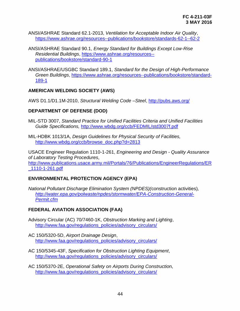
ANSI/ASHRAE Standard 62.1-2013, Ventilation for Acceptable Indoor Air Quality, https://www.ashrae.org/resources--publications/bookstore/standards-62-1--62-2
ANSI/ASHRAE Standard 90.1, Energy Standard for Buildings Except Low-Rise Residential Buildings, https://www.ashrae.org/resources--publications/bookstore/standard-90-1
ANSI/ASHRAE/USGBC Standard 189.1, Standard for the Design of High-Performance Green Buildings, https://www.ashrae.org/resources--publications/bookstore/standard-189-1
AMERICAN WELDING SOCIETY (AWS)
AWS D1.1/D1.1M-2010, Structural Welding Code –Steel, http://pubs.aws.org/
DEPARTMENT OF DEFENSE (DOD)
MIL-STD 3007, Standard Practice for Unified Facilities Criteria and Unified Facilities Guide Specifications, http://www.wbdg.org/ccb/FEDMIL/std3007f.pdf
MIL-HDBK 1013/1A, Design Guidelines for Physical Security of Facilities, http://www.wbdg.org/ccb/browse_doc.php?d=2813
USACE Engineer Regulation 1110-1-261, Engineering and Design - Quality Assurance of Laboratory Testing Procedures, http://www.publications.usace.army.mil/Portals/76/Publications/EngineerRegulations/ER_1110-1-261.pdf
ENVIRONMENTAL PROTECTION AGENCY (EPA)
National Pollutant Discharge Elimination System (NPDES)(construction activities), http://water.epa.gov/polwaste/npdes/stormwater/EPA-Construction-General-Permit.cfm
FEDERAL AVIATION ASSOCIATION (FAA)
Advisory Circular (AC) 70/7460-1K, Obstruction Marking and Lighting, http://www.faa.gov/regulations_policies/advisory_circulars/
AC 150/5320-5D, Airport Drainage Design, http://www.faa.gov/regulations_policies/advisory_circulars/
AC 150/5345-43F, Specification for Obstruction Lighting Equipment, http://www.faa.gov/regulations_policies/advisory_circulars/
AC 150/5370-2E, Operational Safety on Airports During Construction, http://www.faa.gov/regulations_policies/advisory_circulars/
FC 4-211-03F 3 MAY 2016
45
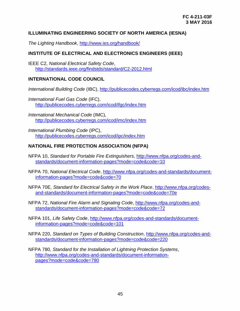
ILLUMINATING ENGINEERING SOCIETY OF NORTH AMERICA (IESNA)
The Lighting Handbook, http://www.ies.org/handbook/
INSTITUTE OF ELECTRICAL AND ELECTRONICS ENGINEERS (IEEE)
IEEE C2, National Electrical Safety Code, http://standards.ieee.org/findstds/standard/C2-2012.html
INTERNATIONAL CODE COUNCIL
International Building Code (IBC), http://publicecodes.cyberregs.com/icod/ibc/index.htm
International Fuel Gas Code (IFC), http://publicecodes.cyberregs.com/icod/ifgc/index.htm
International Mechanical Code (IMC), http://publicecodes.cyberregs.com/icod/imc/index.htm
International Plumbing Code (IPC), http://publicecodes.cyberregs.com/icod/ipc/index.htm
NATIONAL FIRE PROTECTION ASSOCIATION (NFPA)
NFPA 10, Standard for Portable Fire Extinguishers, http://www.nfpa.org/codes-and-standards/document-information-pages?mode=code&code=10
NFPA 70, National Electrical Code, http://www.nfpa.org/codes-and-standards/document-information-pages?mode=code&code=70
NFPA 70E, Standard for Electrical Safety in the Work Place, http://www.nfpa.org/codes-and-standards/document-information-pages?mode=code&code=70e
NFPA 72, National Fire Alarm and Signaling Code, http://www.nfpa.org/codes-and-standards/document-information-pages?mode=code&code=72
NFPA 101, Life Safety Code, http://www.nfpa.org/codes-and-standards/document-information-pages?mode=code&code=101
NFPA 220, Standard on Types of Building Construction, http://www.nfpa.org/codes-and- standards/document-information-pages?mode=code&code=220
NFPA 780, Standard for the Installation of Lightning Protection Systems, http://www.nfpa.org/codes-and-standards/document-information- pages?mode=code&code=780
FC 4-211-03F 3 MAY 2016
46
PUBLIC LAW
Energy Independence and Security Act (EISA) Section 438, Stormwater Management for Federal Facilities under Section 438 of the Energy Independence and Security Act, http://water.epa.gov/polwaste/nps/section438.cfm
Energy Policy Act (EPACT) 2005, http://energy.gov/sites/prod/files/2013/10/f3/epact_2005.pdf
Architectural Barriers Act (ABA), ABA Accessibility Standard for Department of Defense Facilities, http://www.access- board.gov/guidelines-and-standards/buildings-and-sites/about-the-aba- standards/aba-standards
UNIFIED FACILITIES CRITERIA (UFC)
UFC 1-200-01, General Building Requirements, http://www.wbdg.org/ccb/browse_cat.php?o=29&c=4
UFC 1-200-02, High Performance and Sustainability Building Requirements, http://www.wbdg.org/ccb/browse_cat.php?o=29&c=4
UFC 1-300-07A, Design Build Technical Requirements, http://www.wbdg.org/ccb/browse_cat.php?o=29&c=4
UFC 3-101-01, Architecture, http://www.wbdg.org/ccb/browse_cat.php?o=29&c=4
UFC 3-110-03, Roofing, http://www.wbdg.org/ccb/browse_cat.php?o=29&c=4
UFC 3-120-01, Design: Sign Standards, http://www.wbdg.org/ccb/browse_cat.php?o=29&c=4
UFC 3-120-10, Interior Design, http://www.wbdg.org/ccb/browse_cat.php?o=29&c=4
UFC 3-190-06, Protective Coatings and Paints, http://www.wbdg.org/ccb/browse_cat.php?o=29&c=4
UFC 3-201-01, Civil Engineering, http://www.wbdg.org/ccb/browse_cat.php?o=29&c=4
UFC 3-201-02, Landscape Architecture, http://www.wbdg.org/ccb/browse_cat.php?o=29&c=4
UFC 3-210-10, Low Impact Development, http://www.wbdg.org/ccb/browse_cat.php?o=29&c=4
UFC 3-220-01, Geotechnical Engineering, http://www.wbdg.org/ccb/browse_cat.php?o=29&c=4
UFC 3-220-04FA, Backfill for Subsurface Structures, http://www.wbdg.org/ccb/browse_cat.php?o=29&c=4
FC 4-211-03F 3 MAY 2016
47
UFC 3-220-08FA, Engineering Use of Geotextiles, http://www.wbdg.org/ccb/browse_cat.php?o=29&c=4
UFC 3-230-01, Water Storage, Distribution, and Transmission, http://www.wbdg.org/ccb/browse_cat.php?o=29&c=4
UFC 3-240-01, Wastewater Collection, http://www.wbdg.org/ccb/browse_cat.php?o=29&c=4
UFC 3-250-01FA, Pavement Design for Roads, Streets, Walks and Open Storage Areas, http://www.wbdg.org/ccb/browse_cat.php?o=29&c=4
UFC 3-250-04, Standard Practice for Concrete Pavements, http://www.wbdg.org/ccb/browse_cat.php?o=29&c=4
UFC 3-250-08FA, Standard Practice for Sealing Joints and Cracks in Rigid and Flexible Pavements, http://www.wbdg.org/ccb/browse_cat.php?o=29&c=4
UFC 3-250-11, Soil Stabilization for Pavements, http://www.wbdg.org/ccb/browse_cat.php?o=29&c=4
UFC 3-260-01, Airfield and Heliport Planning and Design, http://www.wbdg.org/ccb/browse_cat.php?o=29&c=4
UFC 3-260-17, Dust Control for Roads, Airfields, and Adjacent Areas, http://www.wbdg.org/ccb/browse_cat.php?o=29&c=4
UFC 3-301-01, Design: Structural Engineering, http://www.wbdg.org/ccb/browse_cat.php?o=29&c=4
UFC 3-400-02, Design: Engineering Weather Data, http://www.wbdg.org/ccb/browse_cat.php?o=29&c=4
UFC 3-410-04N, Industrial Ventilation, http://www.wbdg.org/ccb/browse_cat.php?o=29&c=4
UFC 3-420-01, Plumbing Systems, http://www.wbdg.org/ccb/browse_cat.php?o=29&c=4
UFC 3-450-01, Noise and Vibration Control, http://www.wbdg.org/ccb/browse_cat.php?o=29&c=4
UFC 3-501-01, Electrical Engineering, http://www.wbdg.org/ccb/browse_cat.php?o=29&c=4
UFC 3-520-01, Interior Electrical Systems, http://www.wbdg.org/ccb/browse_cat.php?o=29&c=4
FC 4-211-03F 3 MAY 2016
48
UFC 3-530-01, Design: Interior and Exterior Lighting and Controls, http://www.wbdg.org/ccb/browse_cat.php?o=29&c=4
UFC 3-540-01, Engine-Driven Generator Systems for Backup Power Application, http://www.wbdg.org/ccb/browse_cat.php?o=29&c=4
UFC 3-550-01, Exterior Electrical Power Distribution, http://www.wbdg.org/ccb/browse_cat.php?o=29&c=4
UFC 3-570-02A, Cathodic Protection, http://www.wbdg.org/ccb/browse_cat.php?o=29&c=4
UFC 3-575-01, Lightning and Static Electricity Protection Systems, http://www.wbdg.org/ccb/browse_cat.php?o=29&c=4
UFC 3-580-01, Telecommunications Building Cabling Systems Planning and Design, http://www.wbdg.org/ccb/browse_cat.php?o=29&c=4
UFC 4-010-01, DoD Minimum Antiterrorism Standards for Buildings, http://www.wbdg.org/ccb/browse_cat.php?o=29&c=4
UFC 4-010-02, DoD Minimum Antiterrorism Standoff Distances for Buildings, http://www.wbdg.org/ccb/browse_cat.php?o=29&c=4
UFC 4-021-01, Design and O&M: Mass Notification Systems, http://www.wbdg.org/ccb/browse_cat.php?o=29&c=4
UFC 4-022-01, Security Engineering: Entry Control Facilities / Access Control Points, http://www.wbdg.org/ccb/browse_cat.php?o=29&c=4
UFC 4-022-02, Selection and Application of Vehicle Barriers, http://www.wbdg.org/ccb/browse_cat.php?o=29&c=4
UFC 4-022-03, Security Fences and Gates, http://www.wbdg.org/ccb/browse_cat.php?o=29&c=4
UFC 4-023-03, Design of Buildings to Resist Progressive Collapse, http://www.wbdg.org/ccb/browse_cat.php?o=29&c=4
UFC 4-211-01N, Aircraft Maintenance Hangars: Type I, Type II and Type III, http://www.wbdg.org/ccb/browse_cat.php?o=29&c=4
US GREEN BUILDING COUNCIL (USGBC)
USGBC LEED-NC, LEED 2009 for New Construction and Major Renovations Rating System (U.S. Green Building Council), http://www.usgbc.org/Docs/Archive/General/Docs5546.pdf

FC 4-211-03F 3 MAY 2016
49
MISCELLANEOUS
MUTCD, Manual on Uniform Traffic Control Devices, http://www.mutcd.org/

FC 4-211-03F 3 MAY 2016
50
This Page Intentionally Left Blank
FC 4-211-03F 3 MAY 2016
51
APPENDIX B BEST PRACTICES
B-1 ENGINE MAINTENANCE FACILITY PROGRAMMING SHEET.

FC 4-211-03F 3 MAY 2016
52
This Page Intentionally Left Blank

FC 4-211-03F 3 MAY 2016
53
APPENDIX C BIM AND PDF DRAWINGS LINK
BIM & PDF versions of the drawings are available at:
http://www.wbdg.org/references/afbim_tools.php.

FC 4-211-03F 3 MAY 2016
54
This Page Intentionally Left Blank
FC 4-211-03F 3 MAY 2016
55
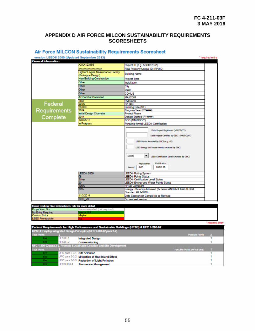
APPENDIX D AIR FORCE MILCON SUSTAINABILITY REQUIREMENTS SCORESHEETS
FC 4-211-03F 3 MAY 2016
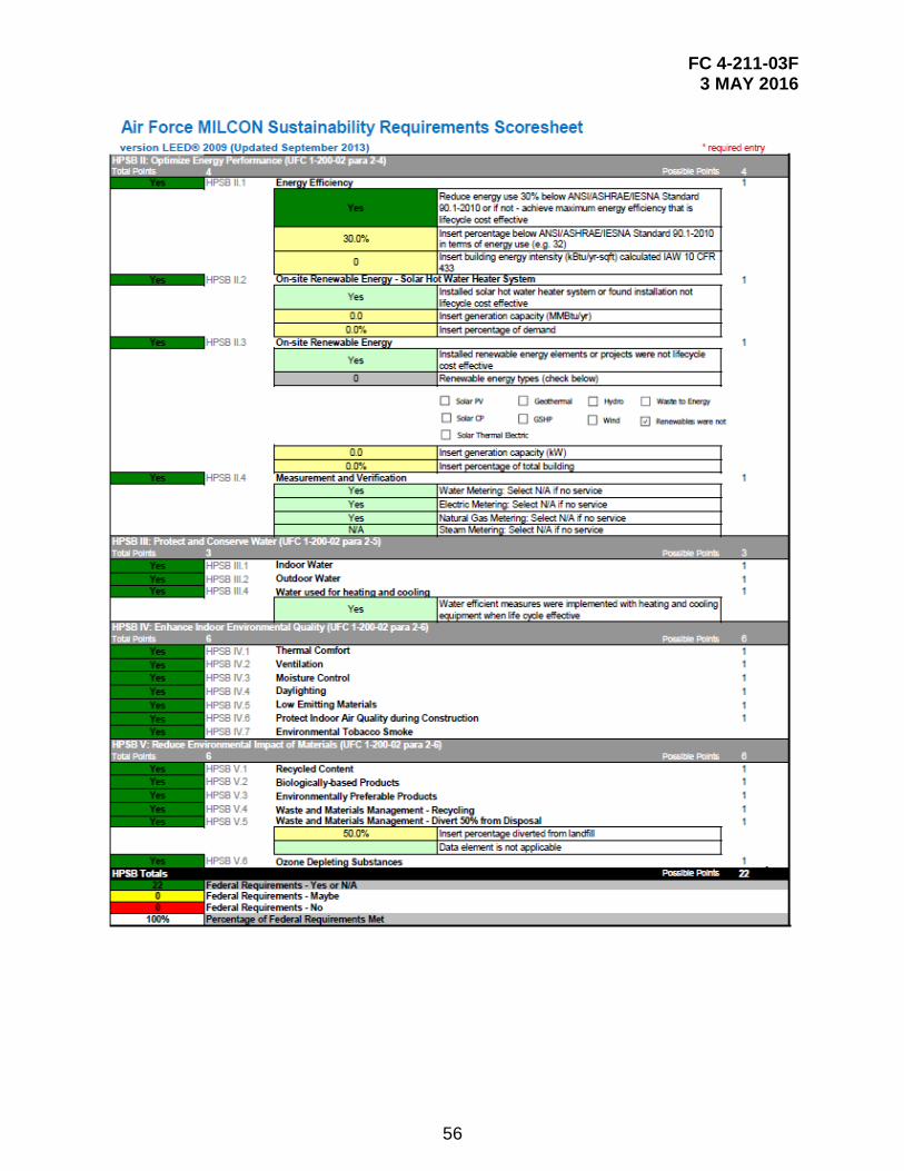
56
FC 4-211-03F 3 MAY 2016
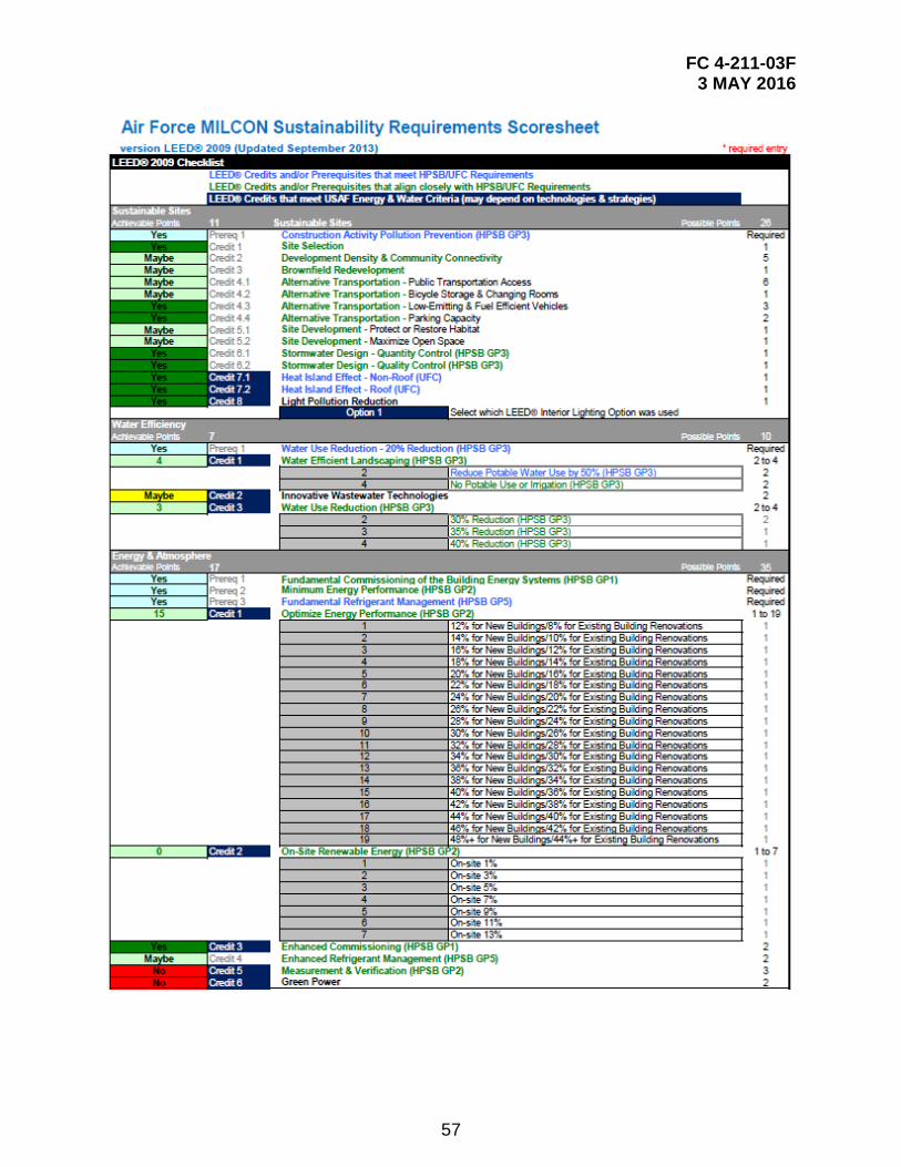
57
FC 4-211-03F 3 MAY 2016
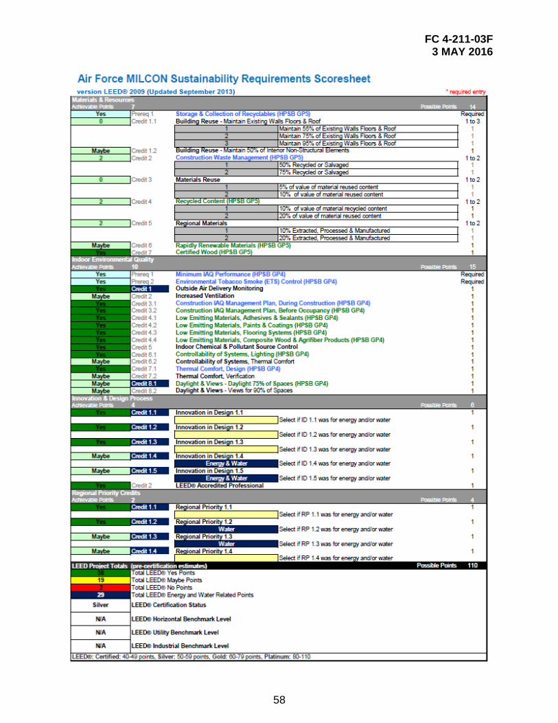
58
FC 4-211-03F 3 MAY 2016
59
APPENDIX E GLOSSARY
E-1 ACRONYMS AND ABBREVIATIONS.
‘ foot
“ inch
A.F.F. above finished floor
ABA Architectural Barriers Ac
AC Advisory Circular
ACI American Concrete Institute
ADP Area Development Plan
A-E Architect-Engineer
AFCEC Air Force Civil Engineer Center
AFCFS Air Force Corporate Facility Standards
AFI Air Force Instruction
AISC American Institute of Steel Construction
AISI American Iron and Steel Institute
AFMAN Air Force Manual
ANSI American National Standards Institute
ASCE American Society of Civil Engineer
ASHRAE American Society of Heating, Refrigerating, and Air Conditioning Engineers
AT antiterrorism
ATFP antiterrorism force protection
AWS American Welding Society
BIA Bilateral Infrastructure Agreements
BIM Building Information Modeling
CATV community access television
FC 4-211-03F 3 MAY 2016
60
CCTV closed circuit television
CMU cement masonry unit
CONUS Continental United States
DoD Department of Defense
EISA Energy Independence and Security Act
EPA Environmental Protection Agency
EPACT 2005 Energy Policy Act of 2005
FAA Federal Aviation Administration
FC Facility Criteria
FF&E furniture, fixtures, and equipment
HNFA Host Nation Funded Construction Agreements
HQ USACE Headquarters United States Army Corps of Engineers
HVAC heating, ventilation, and air conditioning
hZ hertz
IBC International Building Code
IDP Installation Development Plan
IDS intrusion detection system
IEEE Institute of Electrical and Electronics Engineers
IESNA Illuminating Engineering Society of North America
IFC International Fuel Gas code
IMC International Mechanical Code
IPC International Plumbing Code
JEIM jet engine intermediate maintenance
MIL-HDBK Military Handbook
MIL-STD Military Standard
MUTCD Manual on Uniform Traffic Control Devices
FC 4-211-03F 3 MAY 2016
61
N/A not applicable
NAVFAC Naval Facilities Engineering Command
NEC National Electrical Code
NFPA National Fire Protection Association
NIPR non-secure internet protocol router
OCONUS outside continental United States
POV personally-owned vehicle
RFP Request for Proposal
SF square foot
SOFA Status of Forces Agreement
TI Technical Instruction
T.O. Technical Order
UFC Unified Facilities Criteria
USGBC U.S. Green Building Council
V volt
Vdc volts direct current