Embed Size (px)
Citation preview

FC-21-0002 Revision 0
Page 1 of 39
SRRS – 2B.134, DTC – RPA907
FC-21-0002 Revision 0
Description of Embedded Piping, Penetrations, and Buried Pipe to Remain in Fort Calhoun End State
Prepared By: Date
Prepared By: Date
Reviewed By: Date
Approved By: Date
7-23-2021
24-Jul-21
07/24/2021
Michael ReeseDigitally signed by Michael Reese DN: cn=Michael Reese, o, ou, [email protected], c=US Date: 2021.07.23 22:33:10 -04'00'
Jim HomulakDigitally signed by Jim Homulak DN: cn=Jim Homulak, o, ou, [email protected], c=US Date: 2021.07.24 09:18:34 -04'00'
Jason Q SpaideDigitally signed by Jason Q Spaide DN: cn=Jason Q Spaide, o=Reactor D&D Group, ou=11700, [email protected], c=US Date: 2021.07.24 11:19:42 -05'00'

FC-21-0002 Revision 0
Page 2 of 39
SRRS – 2B.134, DTC – RPA907
Table of Contents 1 ISSUE STATEMENT ......................................................................................................................................... 4
2 BACKGROUND ............................................................................................................................................... 4
2.1 EMBEDDED PIPING ............................................................................................................................................ 4 2.2 BURIED PIPING ................................................................................................................................................. 4 2.3 PENETRATIONS ................................................................................................................................................. 5
3 METHODOLOGY ............................................................................................................................................ 5
3.1 GENERAL SURFACE AREA AND VOID SPACE METHOD ............................................................................................... 5 3.2 PRELIMINARY MARSSIM CLASSIFICATION ............................................................................................................. 6
4 ASSUMPTIONS............................................................................................................................................... 6
4.1 EMBEDDED PIPING ............................................................................................................................................ 6 4.2 BURIED PIPING ................................................................................................................................................. 7 4.3 PENETRATIONS ................................................................................................................................................. 7
5 RESULTS ........................................................................................................................................................ 7
5.1 EMBEDDED PIPING ............................................................................................................................................ 7 5.2 BURIED PIPING ................................................................................................................................................. 8 5.3 PENETRATIONS ................................................................................................................................................. 8
6 CALCULATIONS .............................................................................................................................................. 8
6.1 EMBEDDED PIPING ............................................................................................................................................ 8 6.1.1 Turbine Building ....................................................................................................................................... 8 6.1.2 Auxiliary Building ..................................................................................................................................... 9 6.1.3 Containment .......................................................................................................................................... 11 6.1.4 Intake Structure ..................................................................................................................................... 11
6.2 BURIED PIPING ............................................................................................................................................... 11 6.2.1 Yard Drainage ........................................................................................................................................ 11 6.2.2 Service Water ......................................................................................................................................... 17
6.3 PENETRATIONS ............................................................................................................................................... 18 6.3.1 Turbine Building ..................................................................................................................................... 18 6.3.2 Auxiliary Building ................................................................................................................................... 21 6.3.3 Containment .......................................................................................................................................... 22 6.3.4 Intake Structure ..................................................................................................................................... 26
7 REFERENCES ................................................................................................................................................ 29
8 APPENDICES ................................................................................................................................................ 29
FC-21-0002 Revision 0
Page 3 of 39
SRRS – 2B.134, DTC – RPA907
Acronyms and Initialisms
AB Auxiliary Building
ALARA As Low as Reasonably Achievable
BOP Balance of Plant
CB Containment Building
CE Combustion Engineering
CoC Chain-of-Custody
DA Deconstruction Area
DQO Data Quality Objectives
FCS Fort Calhoun Station
FSS Final Status Survey
GPS Global Positioning System
HSA Historical Site Assessment
HTD Hard-to-Detect
LT License Termination
LTP License Termination Plan
MARLAP Multi-Agency Radiological Laboratory Analytical Protocol Manual
MARSSIM Multi-Agency Radiation Survey and Site Investigation Manual
MDC Minimum Detectable Concentration
MDCR Minimum Detectable Count Rate
NMNT New Millennium Nuclear Technologies
NIST National Institute of Standards and Technology
NRC United States Nuclear Regulatory Commission
OPPD Omaha Public Power District
QA Quality Assurance
QAPP Quality Assurance Project Plan
QC Quality Control
RA Radiological Assessment
ROC Radionuclides of Concern
SAF Security Access Facility
SOF Sum of Fractions
TB Turbine Building
TSC Technical Support Center

FC-21-0002 Revision 0
Page 4 of 39
SRRS – 2B.134, DTC – RPA907
1 Issue Statement
The purpose of this document is to provide an inventory of the embedded piping, buried piping, and penetrations that will remain in the end state structures (i.e., below 1001 foot elevation) at the Fort Calhoun Nuclear Generating Station (FCS). The document provides a basis for the estimated lengths and diameters, and also estimates the surface areas and void spaces associated with them. The document also provides the current planned end state (e.g., pipe removed from penetration or pipe remains in penetration). Piping and penetrations, along with elevation and reference drawings for the Yard Piping, Containment Building, Auxiliary Building, Turbine Building and Intake Structure are summarized in Appendices A thru G.
2 Background
2.1 Embedded Piping
Within the building structures to remain in the end state, all accessible piping and some smaller embedded piping will be removed. The larger embedded piping will remain in the end state as they cannot be removed without more extensive demolition of the structure beyond what is planned. The embedded piping to remain is almost entirely comprised of drainage piping in the Turbine Building and Auxiliary Building
2.2 Buried Piping
Buried piping throughout the FCS site consists of multiple systems which support various functions. During the initial investigation of buried piping for this report, all existing piping systems were identified and then it was determined if that system would be removed or left in place. A summary of the identified piping systems and their corresponding material type are shown below in Table 1.
Table 1: Summary of Buried Piping Systems
Piping System Material Type Include in TSD
Waste Drain Stainless Steel
No
Service Water No
Copper Yes/No
Potable Water
No Carbon Steel No
Fiberglass reinforced No
PVC No
Forced Main No Sanitary Sewer
(Plumbing/Drainage) No
VCP No

FC-21-0002 Revision 0
Page 5 of 39
SRRS – 2B.134, DTC – RPA907
Cast Iron No
Storm Drain
CMP Yes/No RCP Yes/No PVC Yes/No
CHDPE Yes/No HDPE Yes/No
Fire Protection Ductile Iron No
Asbestos Cement Lined No
Fuel Oil
Carbon Steel
No Instrument Air No
Compressed Air No Raw Water No Vent Drain No
Auxiliary Steam No Acid No
After each piping system was identified, it was then determined if that system would remain. In general, only select storm drain and service water piping would remain. Other systems (sanitary sewer, fire protection, etc.) would be removed in their entirety, and are therefore not included in this TSD. Table 1 also provides a summary of piping systems that are included in this TSD.
It is also noted that any buried electrical or structural commodities are outside the scope of this TSD.
2.3 Penetrations
Defined as a pipe (or remaining pipe sleeve, if the pipe is removed, or concrete, if the pipe and pipe sleeve is removed) that runs through a concrete wall and/or floor, between two buildings, and is open at the wall or floor surface of each building. A penetration could also be a pipe that runs through a concrete wall and/or floor and opens to a building on one end and the outside ground on the other end.
3 Methodology
3.1 General Surface Area and Void Space Method
The use of the inside versus outside diameter varies depending on whether or not the piping is embedded and cannot be removed but will be left in place and surveyed. If the piping is removed the outer diameter is used unless it is through a larger sleeve, in which case the inside diameter of the sleeve is used. The equation used for the inside surface area is Equation 1.

FC-21-0002 Revision 0
Page 6 of 39
SRRS – 2B.134, DTC – RPA907
𝑺𝑺𝑺𝑺 = 𝟐𝟐𝟐𝟐𝟐𝟐𝟐𝟐 (Equation 1)
Where
SA = Surface area of opening
r = The pipe radius used (inner or outer as described above) or the sleeve radius used.
h = Pipe length in same units as r.
The equation for the void space volume is Equation 2.
𝑽𝑽 = 𝟐𝟐𝟐𝟐𝟐𝟐𝟐𝟐 (Equation 2)
Where
V = Void space volume of opening
r = The pipe radius used (inner or outer as described above) or the sleeve radius used.
h = Pipe length in same units as r.
3.2 Preliminary MARSSIM Classification
Preliminary MARSSIM classifications are assigned to the piping and penetrations evaluated in this document. Classifications are based upon knowledge of Pressurized Water Reactor systems and system contamination levels at FCS. Class 1 systems are those that have a high probability of a Derived Concentration Guideline Level (DCGL) concentration being exceeded. Class 2 MARSSIM lines are those that have a probability of exceeding 50% of the DCGL. These are generally secondary systems with the potential for cross contamination from primary system to secondary system leaks. Class 3 systems are not expected to exceed 50% of the DCGL. These are generally secondary systems with very low probabilities of significant cross contamination due to the volumes of the systems and potential decrees of cross contamination. These classifications are generally based upon the classification of the survey unit in which they originate in and as described in the FCS Historical Site Assessment. MARSSIM classifications are described in Chapter 5 of the License Termination Plan.
4 Assumptions
4.1 Embedded Piping
The following assumptions were made regarding the embedded piping:
1. Start and End Elevations are for the pipe invert elevations for the Turbine Building and centerline elevation for the Auxiliary Building.
2. All embedded piping will be removed from Containment and the Intake Structure.

FC-21-0002 Revision 0
Page 7 of 39
SRRS – 2B.134, DTC – RPA907
4.2 Buried Piping
The following assumptions were made regarding the buried piping:
3. Start and End Elevations are for the pipe invert elevations.
4. Wall thickness for Corrugated Metal Piping (CMP) was assumed based on 16 gage, 2 2/3” x ½” corrugation, in accordance with AASHTO M36. Diameters specified on drawings were taken as the inside diameter of CMP.
5. Wall thickness for Reinforced Concrete Piping (RCP) was assumed based on “B” Wall for Class II, III, IV, and V in accordance with ASTM C-76. Diameters specified on drawings were taken as the inside diameter of RCP.
6. Wall thickness for Polyvinyl Chloride Pipe (PVC) was assumed based on Schedule 40 piping in accordance with ASTM D1785. Diameters specified on drawings were taken as the nominal pipe size.
4.3 Penetrations
The following assumptions were made regarding the penetrations:
1. Start and End Elevations are for the pipe centerline elevations.
2. Penetrations were not listed or considered if they were included in FC-20-006, End State Concrete Surface Areas and Volumes.
5 Results
5.1 Embedded Piping
A summary of all embedded piping is presented below in Table 2. A large majority of the remaining embedded piping will be drainage lines, along with a couple safety injection lines.
Table 2: Total Length, Surface Area, and Void Space of Embedded Piping
Piping Length
(ft)
Interior Surf. Area
(ft2) Void Space
Vol. (ft3) Length
(m)
Interior Surf. Area
(m2) Void Space
Vol. (m3) Drainage 2,585.5 3,504.7 425.8 788.1 325.6 12.1
Safety Injection 17.0 83.7 32.8 5.2 7.8 0.9
Total 2,602.5 3,588.4 458.6 793.2 333.4 13.0 A final breakdown of all embedded piping with estimated lengths, surface areas, and void space is provided in Appendices B&D.

FC-21-0002 Revision 0
Page 8 of 39
SRRS – 2B.134, DTC – RPA907
5.2 Buried Piping
A summary of all buried piping is presented below in Table 3. There were only two systems that would contain buried piping as part of the final end state; storm drain and service water. All other buried piping would be removed from the site. The total surface area and void space volume calculated for these systems is presented in Table 3.
Table 3: Total Length, Surface Area, and Void Space of Buried Piping
Piping Length
(ft)
Interior Surf. Area
(ft2) Void Space
Vol. (ft3) Length
(m)
Interior Surf. Area
(m2) Void Space
Vol. (m3) Storm Drain 3,136.0 23,333.9 17,209.8 955.9 2,167.8 487.3
Service Water 180.0 137.0 8.3 54.9 12.7 0.2 Total 3,316.0 23,470.9 17,218.0 1,010.7 2,180.5 487.6
A final breakdown of all buried piping with estimated lengths, surface areas, and void space is provided in Appendix A.
5.3 Penetrations
A final breakdown of all penetrations with estimated lengths, surface areas, and void space is provided in Appendices C,E,F & G.
6 Calculations
6.1 Embedded Piping
6.1.1 Turbine Building
All piping will be removed from the Turbine Building except for the asbestos-cement drainage lines running below the Turbine Building slab. In 2013, EC46706 installed CIPP inside all of the TB drain piping. A 6mm thick liner or alternate 4.5mm CoREZYN liner was used for the 6” and 10” piping, and a 3mm thick liner was used for the 4” piping. The thinner CoREZYN liner is conservatively assumed for this calculation as it would yield a higher surface area and void volume than the thicker liner. Table 4 presents the resulting inside diameter for each sized pipe with the liner installed.
Table 4: Reduced Drain Piping Inside Diameter with Liner Installed
Nom. Pipe Dia. (in) 4 6 10 Min. Inside Dia. (in) 3.750 5.750 9.750 Liner Thickness (mm) 3.000 4.500 4.500 Liner Thickness (in) 0.120 0.177 0.177 Min. Inside Dia. w/ Liner (in) 3.510 5.396 9.396
FC-21-0002 Revision 0
Page 9 of 39
SRRS – 2B.134, DTC – RPA907
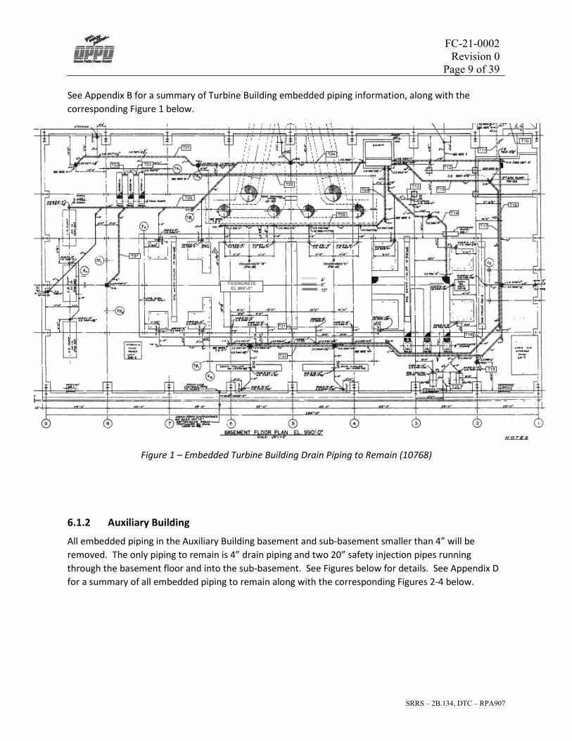
See Appendix B for a summary of Turbine Building embedded piping information, along with the corresponding Figure 1 below.
Figure 1 – Embedded Turbine Building Drain Piping to Remain (10768)
6.1.2 Auxiliary Building
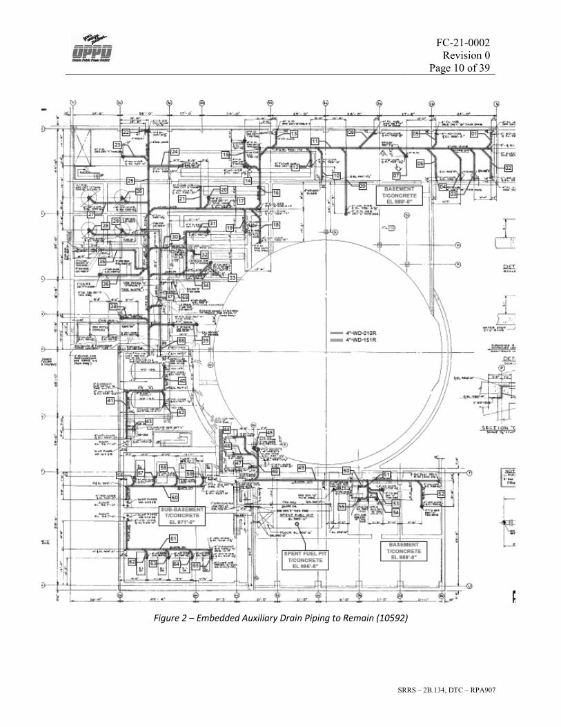
All embedded piping in the Auxiliary Building basement and sub-basement smaller than 4” will be removed. The only piping to remain is 4” drain piping and two 20” safety injection pipes running through the basement floor and into the sub-basement. See Figures below for details. See Appendix D for a summary of all embedded piping to remain along with the corresponding Figures 2-4 below.
FC-21-0002 Revision 0
Page 10 of 39
SRRS – 2B.134, DTC – RPA907
Figure 2 – Embedded Auxiliary Drain Piping to Remain (10592)

FC-21-0002 Revision 0
Page 11 of 39
SRRS – 2B.134, DTC – RPA907
Figure 3 – Plan View 20” SI Piping (10593) Figure 4 – Section View, 20” SI Piping (10603)
6.1.3 Containment
All piping will be removed from Containment. No abandoned piping will remain.
6.1.4 Intake Structure
All piping will be removed from the Intake Structure. No abandoned piping will remain.
6.2 Buried Piping
6.2.1 Yard Drainage
Yard drainage piping can be found throughout the entire site and is intended to direct stormwater runoff away from the site and towards the Missouri review. Yard drainage piping consists of several material types such as CMP, RCP, PVC, CDPE, and HDPE piping. Figure 5 provides an overview of the location of the yard drainage piping throughout the site. Additional details for drainage piping near the Administration building is provided in Figure 6.

FC-21-0002 Revision 0
Page 12 of 39
SRRS – 2B.134, DTC – RPA907
Figure 5 - Yard Drainage - Site Overview

FC-21-0002 Revision 0
Page 13 of 39
SRRS – 2B.134, DTC – RPA907
Figure 6: Yard Drainage – Administration Building
Throughout the life of the site, several upgrades and modifications were made within the property. One example of this was the installation of the Independent Spent Fuel Storage Installation (ISFSI) operation facility located North of the Containment Building. During construction of the facility the original site drainage system was modified to include the installation of several additional pips as shown in Figure 7.

FC-21-0002 Revision 0
Page 14 of 39
SRRS – 2B.134, DTC – RPA907
Figure 7: Yard Drainage – Near ISFSI

FC-21-0002 Revision 0
Page 15 of 39
SRRS – 2B.134, DTC – RPA907
Another modification to the site occurred away from the power block and adjacent to the rail spur near Highway 75. For the decommissioning effort of the site, a temporary building was constructed to assist in the processing and shipment of material from the site via railroad. This structure is commonly called the Waste Processing Structure and was located near the existing rail as shown in Figure 8 and Figure 9.
Figure 8: Yard Drainage – Near Waste Processing Tent

FC-21-0002 Revision 0
Page 16 of 39
SRRS – 2B.134, DTC – RPA907
Figure 9: Yard Drainage – Near Waste Processing Tent (Continued)
There is a total of 9 drainage pipes that consisted of both new and existing lines. The size of the pipes varied from 24” to 84” and consisted entirely of CMP. Details of these pipes can be found on drawings C-01 through C-06 as provided by VIA rail.
The total surface area and void space calculated for this all storm drain piping is provided in Table 5.
Table 5: Total Length, Surface Area, and Void Space of Buried Storm Drain Piping
Piping Length
(ft)
Interior Surf. Area
(ft2) Void Space
Vol. (ft3) Length
(m)
Interior Surf. Area
(m2)
Void Space Vol.
(m3) Storm Drain 3,136.0 23,333.9 17,209.8 955.9 2,167.8 487.3

FC-21-0002 Revision 0
Page 17 of 39
SRRS – 2B.134, DTC – RPA907
6.2.2 Service Water
There was only 1 buried piping identified as service water piping and it was located between the maintenance shop and warehouse. The line was shown on drawing E-4093 Sheet 1 and is also included below as Figure 6.
Figure 10: Service Water – Between Warehouse and Maintenance Shop
The line consisted of 3” copper tubing and extended for a length of approximately 180 ft. The total surface area and void space calculated for this pipe is provided in Table 6.
Table 6: Total Length, Surface Area, and Void Space of Buried Service Water Piping
Piping Length
(ft)
Interior Surf. Area
(ft2) Void Space
Vol. (ft3) Length
(m)
Interior Surf. Area
(m2)
Void Space Vol.
(m3) Service Water 180.0 137.0 8.3 54.9 12.7 0.2

FC-21-0002 Revision 0
Page 18 of 39
SRRS – 2B.134, DTC – RPA907
6.3 Penetrations
6.3.1 Turbine Building
The following Figures 11-19 identify each of the penetrations present in the Turbine Building below EL1001’. Refer to Appendix C for a summary of information pertaining to each penetration identified.
Figure 11 – TB South Wall Penetrations (10753)
Figure 12 – Fire Protection Penetration at A-Line (10755)

FC-21-0002 Revision 0
Page 19 of 39
SRRS – 2B.134, DTC – RPA907
Figure 13 – Unknown Penetration (16526) Figure 14 – Unknown Penetration (16526)
Figure 15 – Sump Pump Discharge Piping (10771)

FC-21-0002 Revision 0
Page 20 of 39
SRRS – 2B.134, DTC – RPA907
Figure 16 – RDS Floor Penetration (10771) Figure 17 – Fire Protection from Service Bldg (44726)
Figure 18 – Circ Water Floor Pen. (35665) Figure 19 – Raw Water Floor Pen (35667)

FC-21-0002 Revision 0
Page 21 of 39
SRRS – 2B.134, DTC – RPA907
Figure 20 – Recirculation Piping of Feedwater Pump FW-54 (54058)
6.3.2 Auxiliary Building
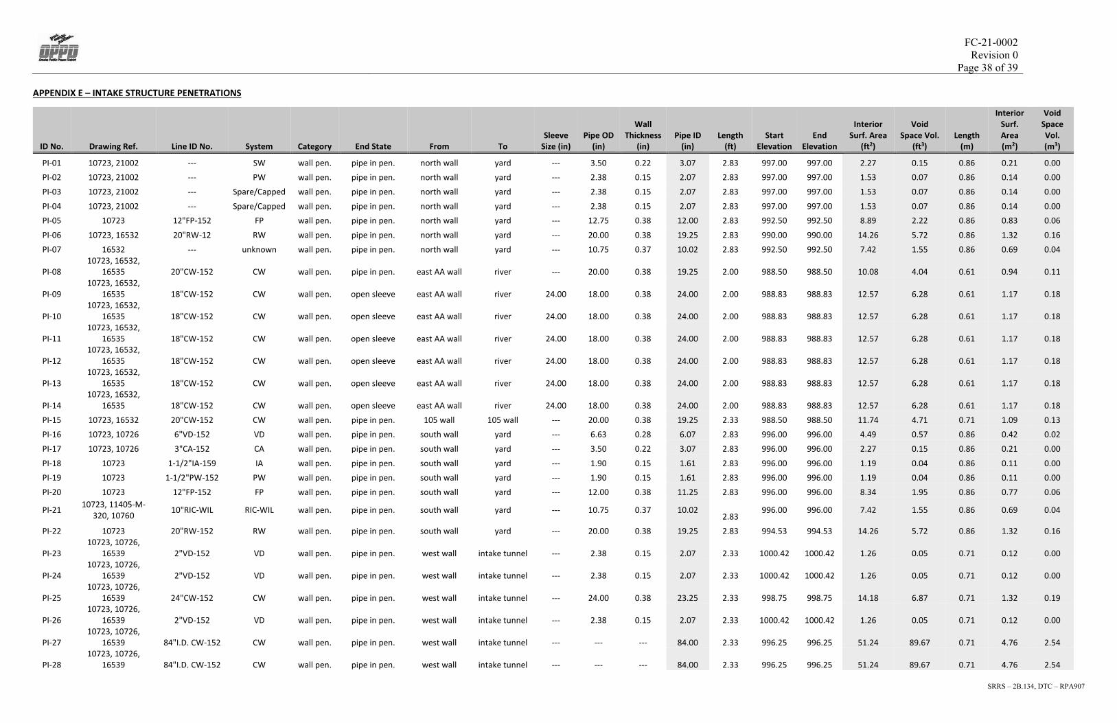
The following Figures 21-23 identify each of the penetrations present in the Auxiliary Building below EL1001’. Refer to Appendix E for a summary of information pertaining to each penetration identified.
Figure 21 – Aux Bldg Room 19 South Wall Penetrations (60139)

FC-21-0002 Revision 0
Page 22 of 39
SRRS – 2B.134, DTC – RPA907
Figure 22 – Raw Water Penetrations at Room 19 South Wall, Plan View (10753)
Figure 23 – Sub-basement North Wall Penetrations (10593)
6.3.3 Containment
The following Figures 24-27 identify each of the penetrations present in Containment below EL1001’. There are several Containment wall penetrations that are located at or close to the EL1001’ cut line that will be exposed with the cut and thus not considered an abandoned penetration in this report. See Figure 27 for an example. Refer to Appendix F for a summary of information pertaining to each penetration identified.

FC-21-0002 Revision 0
Page 23 of 39
SRRS – 2B.134, DTC – RPA907
Figure 24 – Safety Injection from Containment to Aux Bldg (10585)

FC-21-0002 Revision 0
Page 24 of 39
SRRS – 2B.134, DTC – RPA907
Figure 25 – Safety Injection Section Views (10585)

FC-21-0002 Revision 0
Page 25 of 39
SRRS – 2B.134, DTC – RPA907
Figure 26 – Containment Wall Northern Penetrations (10582)

FC-21-0002 Revision 0
Page 26 of 39
SRRS – 2B.134, DTC – RPA907
Figure 27 – Containment Wall Penetration Section 4-4 View (10588)
6.3.4 Intake Structure
The following Figures 28-31 identify each of the penetrations present in the Intake Structure below EL1001’. Refer to Appendix G for a summary of information pertaining to each penetration identified.

FC-21-0002 Revision 0
Page 27 of 39
SRRS – 2B.134, DTC – RPA907
Figure 28 – Intake Structure, Main Structure Penetrations (10723)

FC-21-0002 Revision 0
Page 28 of 39
SRRS – 2B.134, DTC – RPA907
Figure 29 – Unknown 10” Pipe (16532) Figure 30 – Elevation View,
AA Wall Penetrations (16535)
Figure 31 – Penetrations at Intake Tunnel (16539)

FC-21-0002 Revision 0
Page 29 of 39
SRRS – 2B.134, DTC – RPA907
7 References
1. Figure No. 2 (OPPD File: N/A), Rev 5/7/19, “Stormwater Drainage & Controls”
2. C1-2 (OPPD File: N/A), Rev Record Drawing, “Fort Calhoun Administration Building – Site Grading & Storm Sewer Plan”
3. C1-6 (OPPD File: N/A), Rev Record Drawing, “Fort Calhoun Administration Building – Pipe Profiles”
4. C-2 (OPPD File: N/A), Rev Construction Issue, “Fort Calhoun Training Center – Layout Plan” 5. C-3 (OPPD File: N/A), Rev Construction Issue, “Fort Calhoun Training Center – Grading and
Utility Plan” 6. C-8 (OPPD File: N/A), Rev Construction Issue, “Fort Calhoun Training Center – Grading and
Utility Plan – Area B” 7. SKE-09-05-01 (OPPD File: N/A), Rev 1, “Grading Plan GSU XFMR Access Road” 8. C-01 (OPPD File: N/A), Rev 1, “Existing Drainage Map” 9. C-03 (OPPD File: N/A), Rev 1, “Proposed Culverts & Junction Box” 10. C-04 (OPPD File: N/A), Rev 1, “36” Culvert Extension” 11. C-05 (OPPD File: N/A), Rev 1, “24” CMP Culvert & V Ditch” 12. C-06 (OPPD File: N/A), Rev 1, “24” Perforated HDPE Drain”
Additional drawing references included in Appendices by OPPD file number.
8 Appendices
See attached

FC-21-0002 Revision 0
Page 30 of 39
SRRS – 2B.134, DTC – RPA907
APPENDIX A – ABANDONED YARD PIPING
ID No. Drawing Ref. System End State From To Description
Pipe OD (in)
Wall Thickness
(in) Pipe ID
(in) Length
(ft) Start
Elevation End
Elevation
Interior Surf.
Area (ft2)
Void Space
Vol. (ft3) Length
(m)
Interior Surf. Area (m2)
Void Space
Vol. (m3)
1 C1-2, C-2, C-3, C-8 Yard Drain Buried Pipe Admin Building N/A RCP 16.500 2.250 12.000 90.00 1003.05 1002.25 282.74 70.69 27.43 26.27 2.00 2 C1-2, C1-6 Yard Drain Buried Pipe Admin Building N/A RCP 16.500 2.250 12.000 55.00 1000.65 1000.10 172.79 43.20 16.76 16.05 1.22 3 C1-2 Yard Drain Buried Pipe Admin Building N/A RCP 19.500 2.250 15.000 16.00 1000.50 1000.20 62.83 19.63 4.88 5.84 0.56 4 C1-2, C1-6 Yard Drain Buried Pipe Admin Building N/A RCP 30.000 3.000 24.000 105.00 999.27 998.95 659.73 329.87 32.00 61.29 9.34 5 C1-2, C1-6 Yard Drain Buried Pipe Admin Building N/A RCP 30.000 3.000 24.000 152.00 998.95 998.34 955.04 477.52 46.33 88.73 13.52 6 C1-2, C1-6 Yard Drain Buried Pipe Admin Building N/A RCP 37.000 3.500 30.000 225.00 997.88 996.75 1767.15 1104.47 68.58 164.17 31.27 7 C1-2, C1-6 Yard Drain Buried Pipe Admin Building N/A RCP 37.000 3.500 30.000 160.00 996.75 995.38 1256.64 785.40 48.77 116.75 22.24 8 C1-2, C1-6 Yard Drain Buried Pipe Admin Building N/A RCP 44.000 4.000 36.000 33.00 994.98 994.78 311.02 233.26 10.06 28.89 6.61 9 C1-2, C1-6 Yard Drain Buried Pipe Admin Building N/A RCP 44.000 4.000 36.000 62.00 994.78 994.22 584.34 438.25 18.90 54.29 12.41
10 E-4096 (42554) Yard Drain Buried Pipe ISFSI N/A PVC 8.625 0.322 7.981 10.00 1001.90 1001.62 20.89 3.47 3.05 1.94 0.10 11 E-4096 (42554) Yard Drain Buried Pipe ISFSI N/A RCP 23.000 2.500 18.000 98.00 1001.29 1000.31 461.81 173.18 29.87 42.90 4.90 12 E-4096 (42554) Yard Drain Buried Pipe ISFSI N/A RCP 30.000 3.000 24.000 75.00 997.00 996.00 471.24 235.62 22.86 43.78 6.67 13 Figure No. 2 Yard Drain Buried Pipe Shooting Range N/A RCP 44.000 4.000 36.000 65.00 994.20 994.00 612.61 459.46 19.81 56.91 13.01 14 Figure No. 2 Yard Drain Buried Pipe Shooting Range N/A RCP 44.000 4.000 36.000 75.00 994.50 994.20 706.86 530.14 22.86 65.67 15.01 15 Figure No. 2 Yard Drain Buried Pipe Maintenance N/A RCP 23.000 2.500 18.000 200.00 994.50 994.00 942.48 353.43 60.96 87.56 10.01 16 SK-EC70077-C100 (90064) Yard Drain Buried Pipe Maintenance N/A CMP 16.000 0.500 15.000 62.00 998.50 998.00 243.47 76.09 18.90 22.62 2.15 17 SK-EC70077-C100 (90064) Yard Drain Buried Pipe Maintenance N/A RCP 44.000 4.000 36.000 30.00 999.00 998.50 282.74 212.06 9.14 26.27 6.00 18 SK-EC70077-C100 (90064) Yard Drain Buried Pipe Storage Building N/A RCP 23.000 2.500 18.000 50.00 1001.20 1000.00 235.62 88.36 15.24 21.89 2.50 19 SK-EC70077-C100 (90064) Yard Drain Buried Pipe Water Tower N/A RCP 23.000 2.500 18.000 32.00 1001.50 1001.00 150.80 56.55 9.75 14.01 1.60 20 C-3 (42731), C-7 (42751) Yard Drain Buried Pipe Maintenance N/A RCP 23.000 2.500 18.000 50.00 999.39 998.05 235.62 88.36 15.24 21.89 2.50 21 11405-S-283 (16513) Yard Drain Buried Pipe Contractor Office N/A RCP 23.000 2.500 18.000 50.00 999.50 998.25 235.62 88.36 15.24 21.89 2.50 22 48488-S005 (67218) Yard Drain Buried Pipe Access Road N/A RCP 16.500 2.250 12.000 16.00 1002.39 1002.28 50.27 12.57 4.88 4.67 0.36
23 11405-S-283 (16513), C-3
(42731), C-7 (42751) Yard Drain Buried Pipe Access Road N/A RCP 23.000 2.500 18.000 50.00 1001.10 1000.60 235.62 88.36 15.24 21.89 2.50 24 SK-EC70077-C100 (90064) Yard Drain Buried Pipe Maintenance N/A RCP 44.000 4.000 36.000 66.00 1000.70 1000.30 622.04 466.53 20.12 57.79 13.21 25 11405-S-283 (16513) Yard Drain Buried Pipe Switch Yard N/A RCP 51.000 4.500 42.000 58.00 995.00 994.50 637.74 558.03 17.68 59.25 15.80 26 Figure No. 2 Yard Drain Buried Pipe Switch Yard N/A RCP 44.000 4.000 36.000 56.00 995.50 995.00 527.79 395.84 17.07 49.03 11.21 27 Figure No. 2 Yard Drain Buried Pipe Switch Yard N/A RCP 37.000 3.500 30.000 60.00 996.50 996.00 471.24 294.52 18.29 43.78 8.34 28 Figure No. 2 Yard Drain Buried Pipe Switch Yard N/A RCP 37.000 3.500 30.000 70.00 998.00 997.00 549.78 343.61 21.34 51.08 9.73 29 Figure No. 2 Yard Drain Buried Pipe Switch Yard N/A RCP 30.000 3.000 24.000 70.00 996.50 997.00 439.82 219.91 21.34 40.86 6.23 30 SKE-09-05-01 Yard Drain Buried Pipe Switch Yard N/A CHDPE 15.000 0.615 13.770 50.00 1000.40 1000.10 180.25 51.71 15.24 16.75 1.46 31 C-3 Yard Drain Buried Pipe Training Building N/A RCP 19.500 2.250 15.000 44.00 999.66 999.10 172.79 54.00 13.41 16.05 1.53 32 45001 C-01 Yard Drain Buried Pipe Waste Processing Tent N/A CMP 85.000 0.500 84.000 83.00 1007.63 1006.31 1825.27 3194.21 25.30 169.57 90.45 33 45001 C-01 Yard Drain Buried Pipe Waste Processing Tent N/A CMP 25.000 0.500 24.000 50.00 1022.64 1021.73 314.16 157.08 15.24 29.19 4.45 34 45001 C-01, C-04 Yard Drain Buried Pipe Waste Processing Tent N/A CMP 37.000 0.500 36.000 91.00 1005.22 1004.61 857.65 643.24 27.74 79.68 18.21 35 45001 C-01 Yard Drain Buried Pipe Waste Processing Tent N/A CMP 49.000 0.500 48.000 40.00 1003.59 1002.10 502.65 502.65 12.19 46.70 14.23 36 45001 C-01 Yard Drain Buried Pipe Waste Processing Tent N/A CMP 49.000 0.500 48.000 40.00 1003.50 100.86 502.65 502.65 12.19 46.70 14.23 37 45001 C-03 Yard Drain Buried Pipe Waste Processing Tent N/A CMP 61.000 0.500 60.000 66.00 1008.79 1008.00 1036.73 1295.91 20.12 96.31 36.70

FC-21-0002 Revision 0
Page 31 of 39
SRRS – 2B.134, DTC – RPA907
38 45001 C-03 Yard Drain Buried Pipe Waste Processing Tent N/A CMP 61.000 0.500 60.000 66.00 1008.79 1008.00 1036.73 1295.91 20.12 96.31 36.70 39 45001 C-05 Yard Drain Buried Pipe Waste Processing Tent N/A CMP 25.000 0.500 24.000 45.00 1011.43 1010.60 282.74 141.37 13.72 26.27 4.00 40 45001 C-06 Yard Drain Buried Pipe Waste Processing Tent N/A HDPE with sock 24.000 0.923 22.154 420.00 1013.58 1011.88 2435.96 1124.30 128.02 226.31 31.84
41 E-4093 SH 1 (42620) Service Water Buried Pipe Maintenance Shop Warehouse Copper Tube,
Type K 3.125 0.109 2.907 180.00 1000.00 999.00 136.99 8.30 54.86 12.73 0.23
Yard Drain 3136.0 23333.9 17209.8 955.9 2167.8 487.3
Service Water 180.0 137.0 8.3 54.9 12.7 0.2
Total 3316.0 23470.9 17218.0 1010.7 2180.5 487.6
Data for cells highlighted in yellow could not be located on any plant drawing; therefore, conservative assumptions were made for these values.

FC-21-0002 Revision 0
Page 32 of 39
SRRS – 2B.134, DTC – RPA907
APPENDIX B – TURBINE BUILDING ABANDONED PIPING
ID No. Drawing Ref. System Category Description
Nom. Pipe Dia. (in)
Pipe ID (in) Length (ft)
Start Elevation
End Elevation
Interior Surf. Area (ft2)
Void Space Vol. (ft3)
Length (m)
Interior Surf. Area
(m2)
Void Space Vol.
(m3)
T01 M-332 Plumbing & Drainage below slab Asbestos-cement sewer pipe w/ 4.5mm liner 6 5.40 81.54 990.00 987.55 115.19 12.95 24.85 10.70 0.37
T02 M-332 Plumbing & Drainage below slab Asbestos-cement sewer pipe w/ 4.5mm liner 6 5.40 2.54 987.25 987.25 3.59 0.40 0.77 0.33 0.01
T03 M-332 Plumbing & Drainage below slab Asbestos-cement sewer pipe w/ 4.5mm liner 6 5.40 2.54 987.25 987.25 3.59 0.40 0.77 0.33 0.01
T04 M-332 Plumbing & Drainage below slab Asbestos-cement sewer pipe w/ 4.5mm liner 6 5.40 94.55 990.00 987.00 133.56 15.01 28.82 12.41 0.43
T05 M-332 Plumbing & Drainage in & below slab Asbestos-cement sewer pipe w/ 4.5mm liner 6 5.40 101.12 987.25 987.25 142.85 16.06 30.82 13.27 0.45
T06 M-332 Plumbing & Drainage in & below slab Asbestos-cement sewer pipe w/ 4.5mm liner 6 5.40 59.21 990.00 987.57 83.65 9.40 18.05 7.77 0.27
T07 M-332 Plumbing & Drainage below slab Asbestos-cement sewer pipe w/ 4.5mm liner 6 5.40 40.37 990.00 988.42 57.03 6.41 12.31 5.30 0.18
T08 M-332 Plumbing & Drainage below slab Asbestos-cement sewer pipe w/ 4.5mm liner 10 9.40 29.18 990.00 985.70 71.78 14.05 8.89 6.67 0.40
T09 M-332 Plumbing & Drainage below slab Asbestos-cement sewer pipe w/ 4.5mm liner 10 9.40 79.74 990.00 986.42 196.15 38.40 24.30 18.22 1.09
T10 M-332 Plumbing & Drainage below slab Asbestos-cement sewer pipe w/ 3mm liner 4 3.51 10.83 985.00 985.00 9.95 0.73 3.30 0.92 0.02
T11 M-332 Plumbing & Drainage below slab Asbestos-cement sewer pipe w/ 3mm liner 4 3.51 24.44 990.00 984.59 22.46 1.64 7.45 2.09 0.05
T12 M-332 Plumbing & Drainage below slab Asbestos-cement sewer pipe w/ 4.5mm liner 6 5.40 55.51 990.00 984.43 78.42 8.82 16.92 7.29 0.25
T13 M-332 Plumbing & Drainage below slab Asbestos-cement sewer pipe w/ 3mm liner 4 3.51 7.42 990.00 988.42 6.82 0.50 2.26 0.63 0.01
T14 M-332 Plumbing & Drainage below slab Asbestos-cement sewer pipe w/ 4.5mm liner 6 5.40 70.52 986.67 986.67 99.62 11.20 21.49 9.25 0.32
T15 M-332 Plumbing & Drainage below slab Asbestos-cement sewer pipe w/ 4.5mm liner 10 9.40 53.83 990.00 984.38 132.42 25.92 16.41 12.30 0.73
T16 M-332 Plumbing & Drainage below slab Asbestos-cement sewer pipe w/ 4.5mm liner 6 5.40 90.64 990.00 985.42 128.05 14.39 27.63 11.90 0.41
T17 M-332 Plumbing & Drainage below slab Asbestos-cement sewer pipe w/ 4.5mm liner 10 9.40 71.71 990.00 986.64 176.40 34.53 21.86 16.39 0.98
T18 M-332 Plumbing & Drainage below slab Asbestos-cement sewer pipe w/ 4.5mm liner 10 9.40 63.32 990.00 986.03 155.75 30.49 19.30 14.47 0.86
T19 M-332 Plumbing & Drainage below slab Asbestos-cement sewer pipe w/ 4.5mm liner 6 5.40 4.56 990.00 988.42 6.45 0.72 1.39 0.60 0.02
T20 M-332 Plumbing & Drainage below slab Asbestos-cement sewer pipe w/ 3mm liner 4 3.51 19.51 990.00 988.50 17.93 1.31 5.95 1.67 0.04
T21 M-332 Plumbing & Drainage below slab Asbestos-cement sewer pipe w/ 4.5mm liner 10 9.40 76.40 990.00 986.42 187.94 36.79 23.29 17.46 1.04
T22 M-332 Plumbing & Drainage below slab Asbestos-cement sewer pipe w/ 4.5mm liner 6 5.40 127.20 990.00 986.67 179.69 20.20 38.77 16.69 0.57
TOTAL: 1166.69 2009.28 300.33 355.61 186.67 8.50

FC-21-0002 Revision 0
Page 33 of 39
SRRS – 2B.134, DTC – RPA907
APPENDIX C – TURBINE BUILDING PENETRATIONS
ID No. Drawing Ref. Line ID No. System Category End State From To Description
Sleeve Size (in)
Pipe OD (in)
Wall Thickness
(in) Pipe ID
(in) Length
(ft) Elevation End
Elevation Interior Surf.
Area (ft2) Void Space
Vol. (ft3) Length
(m)
Interior Surf. Area
(m2)
Void Space Vol.
(m3)
PT-01 10751, 10753 --- FP south wall pen. pipe in pen. TB Yard 8" C.S. Sch40 N/A 8.63 0.322 7.99 2.00 997.50 997.50 4.18 0.70 0.61 0.39 0.02
PT-02 10751, 10753 --- FP south wall pen. pipe in pen. TB Yard 6" C.S. Sch40 N/A 6.63 0.280 6.07 2.00 997.50 997.50 3.18 0.40 0.61 0.30 0.01
PT-03 10751, 10753 --- FP south wall pen. pipe in pen. TB Yard 10" C.S. Sch40 N/A 10.75 0.365 10.02 2.00 997.50 997.50 5.25 1.10 0.61 0.49 0.03
PT-04 10753 2"AS-152 AS south wall pen. open sleeve TB Yard 10.00 2.38 --- 10.00 2.00 996.00 996.00 5.24 1.09 0.61 0.49 0.03
PT-05 10753, 7531 3"AS-152, AS-5199 AS south wall pen. open sleeve TB Yard 10.00 3.50 --- 10.00 2.00 996.00 996.00 5.24 1.09 0.61 0.49 0.03
PT-06 10753 2"WD-151N WD south wall pen. pipe in pen. TB Yard N/A 2.38 0.154 2.07 2.00 996.00 996.00 1.08 0.05 0.61 0.10 0.00
PT-07 10753, 10748 3"SW-152 SW south wall pen. pipe in pen. TB Yard N/A 3.50 0.216 3.07 2.00 996.00 996.00 1.61 0.10 0.61 0.15 0.00
PT-08 10753, 10748 1 1/2"PW-152 PW south wall pen. pipe in pen. TB Yard N/A 1.90 0.145 1.61 2.00 996.00 996.00 0.84 0.03 0.61 0.08 0.00
PT-09 10753, 16939 1 1/2"IA-159 IA south wall pen. pipe in pen. TB Yard N/A 1.90 0.145 1.61 2.00 996.00 996.00 0.84 0.03 0.61 0.08 0.00
PT-10 10730, 10753 3"CA-152 CA south wall pen. pipe in pen. TB Yard N/A 3.50 0.216 3.07 2.00 996.00 996.00 1.61 0.10 0.61 0.15 0.00
PT-11 10753 6"VD-152 VD south wall pen. pipe in pen. TB Yard N/A 6.63 0.280 6.07 2.00 996.00 996.00 3.18 0.40 0.61 0.30 0.01
PT-12 10753, 10748 10"FP-152 FP south wall pen. pipe in pen. TB Yard 10" C.S. Sch40 N/A 10.75 0.365 10.02 2.00 996.00 996.00 5.25 1.10 0.61 0.49 0.03
PT-13 10751, 10755, 16526 --- FP east wall pen. pipe in pen. TB Service Bldg transite fire protection N/A 10.75 0.365 10.02 2.00 994.50 994.50 5.25 1.10 0.61 0.49 0.03
PT-14 16526 --- unknown east wall pen. open sleeve TB Service Bldg 16.00 --- --- 16.00 2.00 998.50 998.50 8.38 2.79 0.61 0.78 0.08
PT-15 16526 --- unknown east wall pen. open sleeve TB Service Bldg 12.00 --- --- 12.00 2.00 999.75 999.75 6.28 1.57 0.61 0.58 0.04
PT-16 35969, 10771 12"CW-152, IC-425 CW east wall pen. pipe in pen. TB Service Bldg A-106B Sch40 N/A 12.75 0.375 12.00 2.00 998.50 998.50 6.28 1.57 0.61 0.58 0.04
PT-17 44726 --- FP east wall pen. pipe in pen. TB Service Bldg 8" C.S. Sch40 N/A 8.63 0.322 7.98 2.00 998.00 998.00 4.18 0.69 0.61 0.39 0.02
PT-18 10771 --- RDS floor pen. pipe in pen. TB Yard N/A 24.00 0.375 23.25 2.58 990.00 987.42 15.70 7.61 0.79 1.46 0.22
PT-19 35969, 10771 IC-425 CW floor pen. pipe in pen. TB Yard A-106B Sch20 N/A 24.00 0.375 23.25 2.58 990.00 987.42 15.70 7.61 0.79 1.46 0.22
PT-20 35969, 10771 IC-425 CW floor pen. pipe in pen. TB Yard A-106B Sch20 N/A 24.00 0.375 23.25 2.58 990.00 987.42 15.70 7.61 0.79 1.46 0.22
PT-21 35665, 54091 IC-110 CW floor pen. pipe in pen. TB Yard A-106B Sch40 N/A 8.63 0.322 7.98 2.58 990.00 987.42 5.39 0.90 0.79 0.50 0.03
PT-22 35667 IC-112 RW floor pen. pipe in pen. TB Yard 24" A-106B SCH40 N/A 24.00 0.375 23.25 2.58 990.00 987.42 15.70 7.61 0.79 1.46 0.22
PT-23 54058 4"FW-1600 FW east wall pen. pipe in pen. TB Service Bldg N/A 4.50 0.237 4.03 2.00 998.00 998.00 2.11 0.18 0.61 0.20 0.01
TOTAL: 48.90 138.17 45.40 14.90 12.84 1.29

FC-21-0002 Revision 0
Page 34 of 39
SRRS – 2B.134, DTC – RPA907
APPENDIX D – AUXILIARY BUILDING ABANDONED PIPING
ID No. Drawing Ref. Line ID No. System Category Pipe OD
(in)
Wall Thickness
(in) Pipe ID
(in) Length (ft) Start
Elevation End
Elevation Interior Surf.
Area (ft2) Void Space
Vol. (ft3) Length (m)
Interior Surf. Area
(m2) Void Space
Vol. (m3)
A01 11405-M-25 (10592) 4"-WD-010R Waste Disposal Embedded Pipe 4.50 0.24 4.03 9.97 989.00 988.25 10.51 0.88 3.04 0.98 0.02
A02 11405-M-25 (10592) 4"-WD-010R Waste Disposal Embedded Pipe 4.50 0.24 4.03 17.99 989.00 988.25 18.96 1.59 5.48 1.76 0.05
A03 11405-M-25 (10592) 4"-WD-010R Waste Disposal Embedded Pipe 4.50 0.24 4.03 18.12 989.00 988.17 19.10 1.60 5.52 1.77 0.05
A04 11405-M-25 (10592) 4"-WD-010R Waste Disposal Embedded Pipe 4.50 0.24 4.03 19.54 989.00 988.00 20.60 1.73 5.96 1.91 0.05
A05 11405-M-25 (10592) 4"-WD-010R Waste Disposal Embedded Pipe 4.50 0.24 4.03 9.59 989.00 988.25 10.11 0.85 2.92 0.94 0.02
A06 11405-M-25 (10592) 4"-WD-010R Waste Disposal Embedded Pipe 4.50 0.24 4.03 17.89 989.00 988.25 18.86 1.58 5.45 1.75 0.04
A07 11405-M-25 (10592) 4"-WD-010R Waste Disposal Embedded Pipe 4.50 0.24 4.03 6.24 989.00 988.51 6.58 0.55 1.90 0.61 0.02
A08 11405-M-25 (10592) 4"-WD-010R Waste Disposal Embedded Pipe 4.50 0.24 4.03 12.21 989.00 988.25 12.87 1.08 3.72 1.20 0.03
A09 11405-M-25 (10592) 4"-WD-010R Waste Disposal Embedded Pipe 4.50 0.24 4.03 35.96 989.00 988.51 37.90 3.18 10.96 3.52 0.09
A10 11405-M-25 (10592) 4"-WD-010R Waste Disposal Embedded Pipe 4.50 0.24 4.03 18.86 989.00 987.38 19.87 1.67 5.75 1.85 0.05
A11 11405-M-25 (10592) 4"-WD-010R Waste Disposal Embedded Pipe 4.50 0.24 4.03 123.91 989.00 988.04 130.60 10.95 37.77 12.13 0.31
A12 11405-M-25 (10592) 4"-WD-010R Waste Disposal Embedded Pipe 4.50 0.24 4.03 11.59 989.00 988.25 12.22 1.02 3.53 1.13 0.03
A13 11405-M-25 (10592) 4"-WD-010R Waste Disposal Embedded Pipe 4.50 0.24 4.03 11.16 989.00 987.06 11.76 0.99 3.40 1.09 0.03
A14 11405-M-25 (10592) 4"-WD-010R Waste Disposal Embedded Pipe 4.50 0.24 4.03 11.06 989.00 986.89 11.66 0.98 3.37 1.08 0.03
A15 11405-M-25 (10592) 4"-WD-010R Waste Disposal Embedded Pipe 4.50 0.24 4.03 16.78 989.00 987.06 17.68 1.48 5.11 1.64 0.04
A16 11405-M-25 (10592) 4"-WD-010R Waste Disposal Embedded Pipe 4.50 0.24 4.03 35.17 989.00 986.93 37.07 3.11 10.72 3.44 0.09
A17 11405-M-25 (10592) 4"-WD-010R Waste Disposal Embedded Pipe 4.50 0.24 4.03 61.75 989.00 986.58 65.08 5.46 18.82 6.05 0.15
A18 11405-M-25 (10592) 4"-WD-010R Waste Disposal Embedded Pipe 4.50 0.24 4.03 21.46 989.00 986.75 22.62 1.90 6.54 2.10 0.05
A19 11405-M-25 (10592) 4"-WD-010R Waste Disposal Embedded Pipe 4.50 0.24 4.03 13.33 989.00 988.25 14.05 1.18 4.06 1.31 0.03
A20 11405-M-25 (10592) 4"-WD-010R Waste Disposal Embedded Pipe 4.50 0.24 4.03 9.73 989.00 986.33 10.25 0.86 2.96 0.95 0.02
A21 11405-M-25 (10592) 4"-WD-010R Waste Disposal Embedded Pipe 4.50 0.24 4.03 12.64 989.00 988.25 13.32 1.12 3.85 1.24 0.03
A22 11405-M-25 (10592) 4"-WD-010R Waste Disposal Embedded Pipe 4.50 0.24 4.03 4.68 989.00 986.45 4.93 0.41 1.43 0.46 0.01
A23 11405-M-25 (10592) 4"-WD-010R Waste Disposal Embedded Pipe 4.50 0.24 4.03 16.55 989.00 987.00 17.44 1.46 5.04 1.62 0.04
A24 11405-M-25 (10592) 4"-WD-010R Waste Disposal Embedded Pipe 4.50 0.24 4.03 18.33 989.00 988.25 19.32 1.62 5.59 1.79 0.05
A25 11405-M-25 (10592) 4"-WD-010R Waste Disposal Embedded Pipe 4.50 0.24 4.03 120.47 989.00 986.45 126.98 10.65 36.72 11.80 0.30
A26 11405-M-25 (10592) 4"-WD-010R Waste Disposal Embedded Pipe 4.50 0.24 4.03 4.35 989.00 988.51 4.58 0.38 1.33 0.43 0.01
A27 11405-M-25 (10592) 4"-WD-010R Waste Disposal Embedded Pipe 4.50 0.24 4.03 32.82 989.00 988.51 34.59 2.90 10.00 3.21 0.08
A28 11405-M-25 (10592) 4"-WD-010R Waste Disposal Embedded Pipe 4.50 0.24 4.03 32.83 989.00 988.51 34.60 2.90 10.01 3.21 0.08
A29 11405-M-25 (10592) 4"-WD-010R Waste Disposal Embedded Pipe 4.50 0.24 4.03 4.22 989.00 988.51 4.45 0.37 1.29 0.41 0.01
A30 11405-M-25 (10592) 4"-WD-010R Waste Disposal Embedded Pipe 4.50 0.24 4.03 13.10 989.00 986.00 13.81 1.16 3.99 1.28 0.03
A31 11405-M-25 (10592) 4"-WD-010R Waste Disposal Embedded Pipe 4.50 0.24 4.03 36.98 989.00 987.09 38.97 3.27 11.27 3.62 0.09
A32 11405-M-25 (10592) 4"-WD-010R Waste Disposal Embedded Pipe 4.50 0.24 4.03 4.71 989.00 988.25 4.96 0.42 1.44 0.46 0.01
A33 11405-M-25 (10592) 4"-WD-010R Waste Disposal Embedded Pipe 4.50 0.24 4.03 10.66 989.00 987.00 11.24 0.94 3.25 1.04 0.03
A34 11405-M-25 (10592) 4"-WD-010R Waste Disposal Embedded Pipe 4.50 0.24 4.03 32.31 989.00 986.93 34.06 2.86 9.85 3.16 0.08
A35 11405-M-25 (10592) 4"-WD-010R Waste Disposal Embedded Pipe 4.50 0.24 4.03 36.16 989.00 988.25 38.11 3.20 11.02 3.54 0.09

FC-21-0002 Revision 0
Page 35 of 39
SRRS – 2B.134, DTC – RPA907
A36 11405-M-25 (10592) 4"-WD-010R Waste Disposal Embedded Pipe 4.50 0.24 4.03 25.72 989.00 988.51 27.11 2.27 7.84 2.52 0.06
A37 11405-M-25 (10592) 4"-WD-010R Waste Disposal Embedded Pipe 4.50 0.24 4.03 10.35 989.00 985.33 10.91 0.91 3.15 1.01 0.03
A38 11405-M-25 (10592) 4"-WD-010R Waste Disposal Embedded Pipe 4.50 0.24 4.03 18.39 989.00 985.40 19.39 1.63 5.61 1.80 0.05
A39 11405-M-25 (10592) 4"-WD-010R Waste Disposal Embedded Pipe 4.50 0.24 4.03 29.51 989.00 985.35 31.10 2.61 8.99 2.89 0.07
A40 11405-M-25 (10592) 4"-WD-010R Waste Disposal Embedded Pipe 4.50 0.24 4.03 37.83 971.00 969.59 39.87 3.34 11.53 3.70 0.09
A41 11405-M-25 (10592) 4"-WD-010R Waste Disposal Embedded Pipe 4.50 0.24 4.03 27.01 971.00 969.27 28.47 2.39 8.23 2.64 0.07
A42 11405-M-25 (10592) 4"-WD-010R Waste Disposal Embedded Pipe 4.50 0.24 4.03 9.84 971.00 969.60 10.37 0.87 3.00 0.96 0.02
A43 11405-M-25 (10592) 4"-WD-010R Waste Disposal Embedded Pipe 4.50 0.24 4.03 4.81 971.00 970.25 5.07 0.43 1.47 0.47 0.01
A44 11405-M-25 (10592) 4"-WD-010R Waste Disposal Embedded Pipe 4.50 0.24 4.03 16.61 989.00 988.25 17.51 1.47 5.06 1.63 0.04
A45 11405-M-25 (10592) 4"-WD-010R Waste Disposal Embedded Pipe 4.50 0.24 4.03 5.11 989.00 987.21 5.39 0.45 1.56 0.50 0.01
A46 11405-M-25 (10592) 4"-WD-010R Waste Disposal Embedded Pipe 4.50 0.24 4.03 14.36 989.00 988.25 15.14 1.27 4.38 1.41 0.04
A47 11405-M-25 (10592) 4"-WD-010R Waste Disposal Embedded Pipe 4.50 0.24 4.03 5.22 989.00 988.25 5.50 0.46 1.59 0.51 0.01
A48 11405-M-25 (10592) 4"-WD-010R Waste Disposal Embedded Pipe 4.50 0.24 4.03 19.31 989.00 987.21 20.35 1.71 5.89 1.89 0.05
A49 11405-M-25 (10592) 4"-WD-010R Waste Disposal Embedded Pipe 4.50 0.24 4.03 102.25 989.00 988.04 107.77 9.04 31.17 10.01 0.26
A50 11405-M-25 (10592) 4"-WD-010R Waste Disposal Embedded Pipe 4.50 0.24 4.03 5.86 989.00 988.25 6.18 0.52 1.79 0.57 0.01
A51 11405-M-25 (10592) 4"-WD-010R Waste Disposal Embedded Pipe 4.50 0.24 4.03 11.40 989.00 988.25 12.02 1.01 3.47 1.12 0.03
A52 11405-M-25 (10592) 4"-WD-010R Waste Disposal Embedded Pipe 4.50 0.24 4.03 14.95 989.00 988.51 15.76 1.32 4.56 1.46 0.04
A53 11405-M-25 (10592) 4"-WD-010R Waste Disposal Embedded Pipe 4.50 0.24 4.03 8.77 989.00 988.51 9.24 0.78 2.67 0.86 0.02
A54 11405-M-25 (10592) 4"-WD-010R Waste Disposal Embedded Pipe 4.50 0.24 4.03 9.50 989.00 988.25 10.01 0.84 2.90 0.93 0.02
A55 11405-M-25 (10592) 4"-WD-010R Waste Disposal Embedded Pipe 4.50 0.24 4.03 6.08 989.00 988.25 6.41 0.54 1.85 0.60 0.02
A56 11405-M-25 (10592) 4"-WD-010R Waste Disposal Embedded Pipe 4.50 0.24 4.03 7.41 971.00 969.17 7.81 0.66 2.26 0.73 0.02
A57 11405-M-25 (10592) 4"-WD-010R Waste Disposal Embedded Pipe 4.50 0.24 4.03 7.30 971.00 969.28 7.69 0.65 2.22 0.71 0.02
A58 11405-M-25 (10592) 4"-WD-010R Waste Disposal Embedded Pipe 4.50 0.24 4.03 7.18 971.00 969.40 7.57 0.64 2.19 0.70 0.02
A59 11405-M-25 (10592) 4"-WD-010R Waste Disposal Embedded Pipe 4.50 0.24 4.03 7.04 971.00 969.54 7.42 0.62 2.15 0.69 0.02
A60 11405-M-25 (10592) 4"-WD-010R Waste Disposal Embedded Pipe 4.50 0.24 4.03 48.90 971.00 969.50 51.54 4.32 14.90 4.79 0.12
A61 11405-M-25 (10592) 4"-WD-010R Waste Disposal Embedded Pipe 4.50 0.24 4.03 60.61 971.00 969.65 63.89 5.36 18.48 5.94 0.15
A62 11405-M-25 (10592) 4"-WD-010R Waste Disposal Embedded Pipe 4.50 0.24 4.03 7.31 971.00 969.27 7.70 0.65 2.23 0.72 0.02
A63 11405-M-25 (10592) 4"-WD-010R Waste Disposal Embedded Pipe 4.50 0.24 4.03 7.15 971.00 969.43 7.54 0.63 2.18 0.70 0.02
A64 11405-M-25 (10592) 4"-WD-010R Waste Disposal Embedded Pipe 4.50 0.24 4.03 7.00 971.00 969.58 7.37 0.62 2.13 0.69 0.02
A65 11405-M-25 (10592) 4"-WD-010R Waste Disposal Embedded Pipe 4.50 0.24 4.03 6.89 971.00 969.69 7.26 0.61 2.10 0.67 0.02
A66 11405-M-25 (10592) 4"-WD-151R Waste Disposal Embedded Pipe 4.50 0.24 4.03 6.00 988.00 985.00 6.32 0.53 1.83 0.59 0.02 A67 10593 20"SI-151R SI Embedded Pipe 20.00 0.59 18.81 8.50 989.00 983.00 41.86 16.41 2.59 3.89 0.46
A68 10593 20"SI-151R SI Embedded Pipe 20.00 0.59 18.81 8.50 989.00 983.00 41.86 16.41 2.59 3.89 0.46
TOTAL: 1435.78 1579.13 158.24 437.63 146.71 4.48

FC-21-0002 Revision 0
Page 36 of 39
SRRS – 2B.134, DTC – RPA907
APPENDIX E – AUXILIARY BUILDING PENETRATIONS
ID No. Drawing Ref. Line ID No. System Category End State From To Description Sleeve
Size (in) Pipe OD
(in)
Wall Thickness
(in) Pipe ID
(in) Length
(ft) Start
Elevation End
Elevation
Interior Surf. Area
(ft2)
Void Space
Vol. (ft3) Length (m)
Interior Surf. Area
(m2)
Void Space Vol.
(m3)
PA-01 60139 19-S-59 flood barrier
pen. wall pen. unknown Rm 19 south wall yard assumed 12"
sleeve 12.00 --- --- 12.00 2.00 997.00 997.00 6.28 1.57 0.61 0.58 0.04
PA-02 60139 19-S-60 flood barrier
pen. wall pen. unknown Rm 19 south wall yard assumed 12"
sleeve 12.00 --- --- 12.00 2.00 997.00 997.00 6.28 1.57 0.61 0.58 0.04
PA-03 60139, 10753, 10596 20"RW-152 RW wall pen. open sleeve Rm 19 south wall yard 28"OD Sch40
sleeve 28.00 20.00 --- 27.25 2.00 996.00 996.00 14.27 8.10 0.61 1.33 0.23
PA-04 60139, 10753, 10596 20"RW-152 RW wall pen. open sleeve Rm 19 south wall yard 28"OD Sch40
sleeve 28.00 20.00 --- 27.25 2.00 996.00 996.00 14.27 8.10 0.61 1.33 0.23
PA-05 10593 4"WD-010R WD wall pen. pipe in pen. sub-basement
north wall yard N/A 4.50 0.24 4.03 2.00 977.50 977.50 2.11 0.18 0.61 0.20 0.01
PA-06 10593 4"WD-010R WD wall pen. pipe in pen. sub-basement
north wall yard N/A 4.50 0.24 4.03 2.00 977.50 977.50 2.11 0.18 0.61 0.20 0.01
PA-07 10593 4"WD-010R WD wall pen. pipe in pen. sub-basement
north wall yard N/A 4.50 0.24 4.03 2.00 977.50 977.50 2.11 0.18 0.61 0.20 0.01
TOTAL: 14.00 47.43 19.87 4.27 4.41 0.56

FC-21-0002 Revision 0
Page 37 of 39
SRRS – 2B.134, DTC – RPA907
APPENDIX F – CONTAINMENT PENETRATIONS
ID No. Drawing Ref. Line ID No. System Category End State From To Sleeve
Size (in) Pipe OD
(in)
Wall Thickness
(in) Pipe ID
(in) Length
(ft) Start
Elevation End
Elevation
Interior Surf. Area
(ft2)
Void Space Vol.
(ft3) Length
(m)
Interior Surf. Area (m2)
Void Space Vol. (m3)
PC-01 10585 24"-SI-151R Safety Injection floor/wall
pen. pipe in pen. Containment Aux. Bldg N/A 24.00 0.69 22.62 39.21 991.00 981.50 232.24 109.46 11.95 21.58 3.10
PC-02 10585 24"-SI-151R Safety Injection floor/wall
pen. pipe in pen. Containment Aux. Bldg N/A 24.00 0.69 22.62 40.20 991.00 981.50 238.10 112.23 12.25 22.12 3.18
PC-03 10582 1 1/2"AC-152 Nuc. Detector Well floor/wall
pen. pipe in pen. Containment Aux. Bldg N/A 1.90 0.15 1.61 4.85 998.67 998.67 2.04 0.07 1.48 0.19 0.00
PC-04 10582 3"WD-152R Vent Header floor/wall
pen. pipe in pen. Containment Aux. Bldg N/A 3.50 0.22 3.07 4.85 998.67 998.67 3.90 0.25 1.48 0.36 0.01
PC-05 10582 3"FW-1000 Stm Gen Blowdown floor/wall
pen. pipe in pen. Containment Aux. Bldg N/A 3.50 0.22 3.07 4.85 998.67 998.67 3.90 0.25 1.48 0.36 0.01
PC-06 10582 2"FW-602 Stm Gen Drain floor/wall
pen. pipe in pen. Containment Aux. Bldg N/A 2.38 0.15 2.07 4.85 998.67 998.67 2.62 0.11 1.48 0.24 0.00
PC-07 10582 1 1/2"AC-152 Nuc. Detector Well floor/wall
pen. pipe in pen. Containment Aux. Bldg N/A 1.90 0.15 1.61 4.85 998.25 998.25 2.04 0.07 1.48 0.19 0.00
PC-08 10582 3"FW-1000 Stm Gen Blowdown floor/wall
pen. pipe in pen. Containment Aux. Bldg N/A 3.50 0.22 3.07 4.85 998.67 998.67 3.90 0.25 1.48 0.36 0.01
PC-09 10582 2"FW-602 Stm Gen Drain floor/wall
pen. pipe in pen. Containment Aux. Bldg N/A 2.38 0.15 2.07 4.85 998.67 998.67 2.62 0.11 1.48 0.24 0.00
PC-10 10582 2"WD-151R Cont Sump Pumps
Disch. floor/wall
pen. pipe in pen. Containment Aux. Bldg N/A 2.38 0.15 2.07 4.85 998.67 998.67 2.62 0.11 1.48 0.24 0.00
PC-11 10582, 10588 3/4"CH-2501R RC Pump Bleed Off floor/wall
pen. pipe in pen. Containment Aux. Bldg N/A 1.05 0.11 0.82 4.85 998.67 998.67 1.05 0.02 1.48 0.10 0.00
PC-12 10582 4"SI-1503R HP Safety Injection floor/wall
pen. pipe in pen. Containment Aux. Bldg N/A 4.50 0.24 4.03 4.85 998.69 998.69 5.11 0.43 1.48 0.47 0.01
PC-13 10582 2"CH-2501R Charging Pump floor/wall
pen. pipe in pen. Containment Aux. Bldg N/A 2.38 0.15 2.07 5.16 996.33 996.33 2.79 0.12 1.57 0.26 0.00
PC-14 10582 4"SI-2501R HP Safety Injection floor/wall
pen. pipe in pen. Containment Aux. Bldg N/A 4.50 0.24 4.03 4.85 998.67 998.67 5.11 0.43 1.48 0.47 0.01
PC-15 10582 2"CH-2501R Letdown Heat Exch. floor/wall
pen. pipe in pen. Containment Aux. Bldg N/A 2.38 0.15 2.07 5.16 996.33 996.33 2.79 0.12 1.57 0.26 0.00
TOTAL: 143.08 510.84 224.03 43.61 47.46 6.34
FC-21-0002 Revision 0
Page 38 of 39
SRRS – 2B.134, DTC – RPA907
APPENDIX E – INTAKE STRUCTURE PENETRATIONS
ID No. Drawing Ref. Line ID No. System Category End State From To Sleeve
Size (in) Pipe OD
(in)
Wall Thickness
(in) Pipe ID
(in) Length
(ft) Start
Elevation End
Elevation
Interior Surf. Area
(ft2)
Void Space Vol.
(ft3) Length
(m)
Interior Surf. Area (m2)
Void Space Vol. (m3)
PI-01 10723, 21002 --- SW wall pen. pipe in pen. north wall yard --- 3.50 0.22 3.07 2.83 997.00 997.00 2.27 0.15 0.86 0.21 0.00 PI-02 10723, 21002 --- PW wall pen. pipe in pen. north wall yard --- 2.38 0.15 2.07 2.83 997.00 997.00 1.53 0.07 0.86 0.14 0.00
PI-03 10723, 21002 --- Spare/Capped wall pen. pipe in pen. north wall yard --- 2.38 0.15 2.07 2.83 997.00 997.00 1.53 0.07 0.86 0.14 0.00
PI-04 10723, 21002 --- Spare/Capped wall pen. pipe in pen. north wall yard --- 2.38 0.15 2.07 2.83 997.00 997.00 1.53 0.07 0.86 0.14 0.00 PI-05 10723 12"FP-152 FP wall pen. pipe in pen. north wall yard --- 12.75 0.38 12.00 2.83 992.50 992.50 8.89 2.22 0.86 0.83 0.06
PI-06 10723, 16532 20"RW-12 RW wall pen. pipe in pen. north wall yard --- 20.00 0.38 19.25 2.83 990.00 990.00 14.26 5.72 0.86 1.32 0.16
PI-07 16532 --- unknown wall pen. pipe in pen. north wall yard --- 10.75 0.37 10.02 2.83 992.50 992.50 7.42 1.55 0.86 0.69 0.04
PI-08 10723, 16532,
16535 20"CW-152 CW wall pen. pipe in pen. east AA wall river --- 20.00 0.38 19.25 2.00 988.50 988.50 10.08 4.04 0.61 0.94 0.11
PI-09 10723, 16532,
16535 18"CW-152 CW wall pen. open sleeve east AA wall river 24.00 18.00 0.38 24.00 2.00 988.83 988.83 12.57 6.28 0.61 1.17 0.18
PI-10 10723, 16532,
16535 18"CW-152 CW wall pen. open sleeve east AA wall river 24.00 18.00 0.38 24.00 2.00 988.83 988.83 12.57 6.28 0.61 1.17 0.18
PI-11 10723, 16532,
16535 18"CW-152 CW wall pen. open sleeve east AA wall river 24.00 18.00 0.38 24.00 2.00 988.83 988.83 12.57 6.28 0.61 1.17 0.18
PI-12 10723, 16532,
16535 18"CW-152 CW wall pen. open sleeve east AA wall river 24.00 18.00 0.38 24.00 2.00 988.83 988.83 12.57 6.28 0.61 1.17 0.18
PI-13 10723, 16532,
16535 18"CW-152 CW wall pen. open sleeve east AA wall river 24.00 18.00 0.38 24.00 2.00 988.83 988.83 12.57 6.28 0.61 1.17 0.18
PI-14 10723, 16532,
16535 18"CW-152 CW wall pen. open sleeve east AA wall river 24.00 18.00 0.38 24.00 2.00 988.83 988.83 12.57 6.28 0.61 1.17 0.18
PI-15 10723, 16532 20"CW-152 CW wall pen. pipe in pen. 105 wall 105 wall --- 20.00 0.38 19.25 2.33 988.50 988.50 11.74 4.71 0.71 1.09 0.13 PI-16 10723, 10726 6"VD-152 VD wall pen. pipe in pen. south wall yard --- 6.63 0.28 6.07 2.83 996.00 996.00 4.49 0.57 0.86 0.42 0.02
PI-17 10723, 10726 3"CA-152 CA wall pen. pipe in pen. south wall yard --- 3.50 0.22 3.07 2.83 996.00 996.00 2.27 0.15 0.86 0.21 0.00
PI-18 10723 1-1/2"IA-159 IA wall pen. pipe in pen. south wall yard --- 1.90 0.15 1.61 2.83 996.00 996.00 1.19 0.04 0.86 0.11 0.00 PI-19 10723 1-1/2"PW-152 PW wall pen. pipe in pen. south wall yard --- 1.90 0.15 1.61 2.83 996.00 996.00 1.19 0.04 0.86 0.11 0.00
PI-20 10723 12"FP-152 FP wall pen. pipe in pen. south wall yard --- 12.00 0.38 11.25 2.83 996.00 996.00 8.34 1.95 0.86 0.77 0.06
PI-21 10723, 11405-M-320, 10760 10"RIC-WIL RIC-WIL wall pen. pipe in pen. south wall yard --- 10.75 0.37 10.02
2.83 996.00 996.00 7.42 1.55 0.86 0.69 0.04
PI-22 10723 20"RW-152 RW wall pen. pipe in pen. south wall yard --- 20.00 0.38 19.25 2.83 994.53 994.53 14.26 5.72 0.86 1.32 0.16
PI-23 10723, 10726,
16539 2"VD-152 VD wall pen. pipe in pen. west wall intake tunnel --- 2.38 0.15 2.07 2.33 1000.42 1000.42 1.26 0.05 0.71 0.12 0.00
PI-24 10723, 10726,
16539 2"VD-152 VD wall pen. pipe in pen. west wall intake tunnel --- 2.38 0.15 2.07 2.33 1000.42 1000.42 1.26 0.05 0.71 0.12 0.00
PI-25 10723, 10726,
16539 24"CW-152 CW wall pen. pipe in pen. west wall intake tunnel --- 24.00 0.38 23.25 2.33 998.75 998.75 14.18 6.87 0.71 1.32 0.19
PI-26 10723, 10726,
16539 2"VD-152 VD wall pen. pipe in pen. west wall intake tunnel --- 2.38 0.15 2.07 2.33 1000.42 1000.42 1.26 0.05 0.71 0.12 0.00
PI-27 10723, 10726,
16539 84"I.D. CW-152 CW wall pen. pipe in pen. west wall intake tunnel --- --- --- 84.00 2.33 996.25 996.25 51.24 89.67 0.71 4.76 2.54
PI-28 10723, 10726,
16539 84"I.D. CW-152 CW wall pen. pipe in pen. west wall intake tunnel --- --- --- 84.00 2.33 996.25 996.25 51.24 89.67 0.71 4.76 2.54

FC-21-0002 Revision 0
Page 39 of 39
SRRS – 2B.134, DTC – RPA907
PI-29 10723, 10726,
16539 84"I.D. CW-152 CW wall pen. pipe in pen. west wall intake tunnel --- --- --- 84.00 2.33 996.25 996.25 51.24 89.67 0.71 4.76 2.54 PI-30 16539 2"VD-152 VD wall pen. pipe in pen. intake tunnel west wall --- 2.38 0.15 2.07 2.33 1000.42 1000.42 1.26 0.05 0.71 0.12 0.00
PI-31 16539 2"VD-152 VD wall pen. pipe in pen. intake tunnel west wall --- 2.38 0.15 2.07 2.33 1000.42 1000.42 1.26 0.05 0.71 0.12 0.00
PI-32 16539, 48183 24"CW-152 CW wall pen. 3'x3' opening intake tunnel west wall --- --- --- --- 2.33 998.75 998.75 27.96 20.97 0.71 2.60 0.59 PI-33 16539 2"VD-152 VD wall pen. pipe in pen. intake tunnel west wall --- 2.38 0.15 2.07 2.33 1000.42 1000.42 1.26 0.05 0.71 0.12 0.00
PI-34 16539 84"I.D. CW-152 CW wall pen. 8'x10' opening intake tunnel west wall --- --- --- --- 2.33 996.25 996.25 83.88 186.40 0.71 7.79 5.28
PI-35 16539 84"I.D. CW-152 CW wall pen. 8'x10' opening intake tunnel west wall --- --- --- --- 2.33 996.25 996.25 83.88 186.40 0.71 7.79 5.28 PI-36 16539 84"I.D. CW-152 CW wall pen. 8'x8' opening intake tunnel west wall --- --- --- --- 2.33 996.25 996.25 74.56 149.12 0.71 6.93 4.22
TOTAL: 88.57 619.58 885.39 27.00 57.56 25.07


![2015 / 16...Southampton FC Stoke City FC Sunderland AFC Swansea City AFC Tottenham Hotspur FC [London ] Watford FC West Bromwich Albion FC West Ham United FC [London ] …](https://img.pdfslide.us/doc/110x75/6147d88ca830d0442101b33e/2015-16-southampton-fc-stoke-city-fc-sunderland-afc-swansea-city-afc-tottenham.jpg)