Embed Size (px)
Citation preview
Kramer Electronics, Ltd.
USER MANUAL ����
Model: FC-10Dxl Composite-YC-Component Transcoder
Contents
i
Contents
1 Introduction 1 2 Getting Started 1 2.1 Quick Start 1 3 Overview 3 4 Your FC-10Dxl Composite-YC-Component Transcoder 4 5 Connecting the FC-10Dxl Composite-YC-Component Transcoder 5 5.1 Controlling via the REMOTE INPUT SELECT Connector 6 6 Technical Specifications 6
Figures
Figure 1: FC-10Dxl Composite-YC-Component Transcoder 4 Figure 2: Connecting the FC-10Dxl Composite-YC-Component Transcoder 5 Figure 3: Connecting the REMOTE INPUT SELECT Connector 6
Tables
Table 1: FC-10Dxl Composite-YC-Component Transcoder Features 4 Table 2: Technical Specifications, of the FC-10Dxl 6

Introduction
1
1 Introduction
Welcome to Kramer Electronics! Since 1981, Kramer Electronics has been providing a world of unique, creative, and affordable solutions to the vast range of problems that confront the video, audio, presentation, and broadcasting professional on a daily basis. In recent years, we have redesigned and upgraded most of our line, making the best even better! Our 1,000-plus different models now appear in 11 groups1 that are clearly defined by function.
Congratulations on purchasing your Kramer FC-10Dxl Composite-YC-Component Transcoder, which is ideal for the following typical applications: � Video production, editing and duplication studios � Interfacing between machines with differing formats
The package includes the following items: � FC-10Dxl Composite-YC-Component Transcoder � Power adapter (12V DC Input)
2 Getting Started
We recommend that you: � Unpack the equipment carefully and save the original box and packaging
materials for possible future shipment � Review the contents of this user manual � Use Kramer high performance high resolution cables2
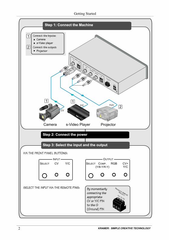
2.1 Quick Start
This quick start chart summarizes the basic setup and operation steps.
1 GROUP 1: Distribution Amplifiers; GROUP 2: Switchers and Matrix Switchers; GROUP 3: Control Systems; GROUP 4:
Format/Standards Converters; GROUP 5: Range Extenders and Repeaters; GROUP 6: Specialty AV Products; GROUP 7:
Scan Converters and Scalers; GROUP 8: Cables and Connectors; GROUP 9: Room Connectivity; GROUP 10: Accessories
and Rack Adapters; GROUP 11: Sierra Products
2 The complete list of Kramer cables is on our Web site at http://www.kramerelectronics.com
KRAMER: SIMPLE CREATIVE TECHNOLOGY
Getting Started
2

Overview
3
3 Overview
The FC-10Dxl is a high-performance video format converter for composite and s-Video (Y/C) signals. The unit converts a composite video or s-Video input through a digital comb filter to a composite and s-Video (Y/C) or component (YUV/RGB1) video output.
The FC-10Dxl features: � Selectable inputs - one composite (RCA connector) and one s-Video (4-pin
connector) � Format conversion - Transcodes composite video and s-Video to component
video, RGB1, or composite video and s-Video � One component video output and one composite video output on RCA
connectors, as well as one s-Video output (on RCA connectors/4-pin connector)
� A front panel input select button and an output format select button � A contact closure remote input select terminal block connector � 3D comb filtering for best quality color separation � PAL/NTSC compatibility � Compact size. Two units can be rack mounted side-by-side in a 1U rack
space with the optional RK-1 rack kit
To achieve the best performance: � Connect only good quality connection cables, thus avoiding interference,
deterioration in signal quality due to poor matching, and elevated noise levels (often associated with low quality cables)
� Avoid interference from neighboring electrical appliances that may adversely influence signal quality
� Position your Kramer FC-10Dxl in a location free from moisture and away from excessive sunlight and dust
Caution – No operator-serviceable parts inside unit.
Warning – Use only the Kramer Electronics input power wall adapter that is provided with this unit2.
Warning – Disconnect power and unplug unit from wall before installing or removing device or servicing unit.
1 Defined as RsGsBs (that is, there is sync on all three components of the RGB outputs)
2 For example: model number AD2512C, part number 2535-000251

KRAMER: SIMPLE CREATIVE TECHNOLOGY
Your FC-10Dxl Composite-YC-Component Transcoder
4
4 Your FC-10Dxl Composite-YC-Component Transcoder
Figure 1 and Table 1 define the FC-10Dxl.
Figure 1: FC-10Dxl Composite-YC-Component Transcoder
Table 1: FC-10Dxl Composite-YC-Component Transcoder Features
# Feature Function 1 POWER Switch Illuminated switch for turning the unit ON or OFF 2 SELECT Button Press to select the input format (CV or Y/C) CV LED Lights when the CV input is selected
INPUT Area
Y/C LED Lights when the Y/C input is selected 3 SELECT Button Press to select the desired output format COMP. (Y/B-Y/R-Y) LED Lights when the component video output format is selected RGB LED Lights when the RsGsBs output format is selected
OUTPUT Area
CV+Y/C LED Lights when the CV as well as the Y/C output format is selected
4 CV RCA Connector Connect to the CV source
INPUT Y/C 4-pin Connector Connect to the s-Video source
5 Y/G RCA Connector B-Y/B/CV RCA Connector R-Y/R/C RCA Connector
Connect to the CV (via B-Y/B/CV) and/or to the s-Video1 (Y/G and R-Y/R/C) acceptor, or to the component acceptor
OUTPUT
Y/C 4-pin Connector Connect to the s-Video1 acceptor 6 REMOTE INPUT SELECT Terminal
Block Connector Connect to contact closure switches (see section �5.1)
7 12V DC +12V DC connector for powering the unit
1 If the s-Video acceptor is connected to the Y/C 4-pin connector, you cannot connect to the Y/G and R-Y/R/C RCA
connectors and vice versa

Connecting the FC-10Dxl Composite-YC-Component Transcoder
5
5 Connecting the FC-10Dxl Composite-YC-Component Transcoder
To connect the FC-10Dxl, as the example in Figure 2 illustrates, do the following1:
1. Connect one or both of the following sources: � A composite video source (for example, a camera) to the CV INPUT
RCA connector � A Y/C source (for example, an s-Video player) to the 4-pin INPUT
connector
2. Connect the Y/G, B-Y/B/CV, and R-Y/R/C RCA connectors to the component video acceptor (for example, a projector)2.
3. Connect the 12V DC power adapter to the power socket and connect the adapter to the mains electricity3.
Figure 2: Connecting the FC-10Dxl Composite-YC-Component Transcoder
1 Switch OFF the power on each device before connecting it to your FC-10Dxl. After connecting your FC-10Dxl, switch on
its power and then switch on the power on each device
2 Alternatively, you can connect a CV, Y/C or RGB acceptor to the RCA connectors, or an s-Video acceptor to the Y/C 4-pin
connector
3 Not illustrated in Figure 2
KRAMER: SIMPLE CREATIVE TECHNOLOGY
Technical Specifications
6
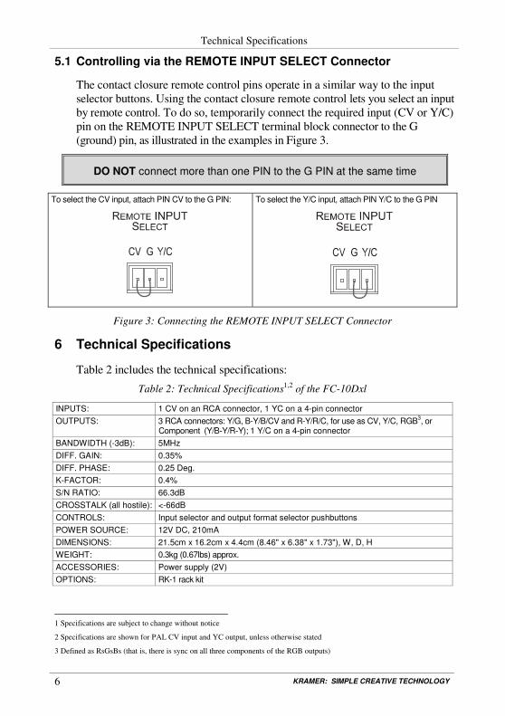
5.1 Controlling via the REMOTE INPUT SELECT Connector
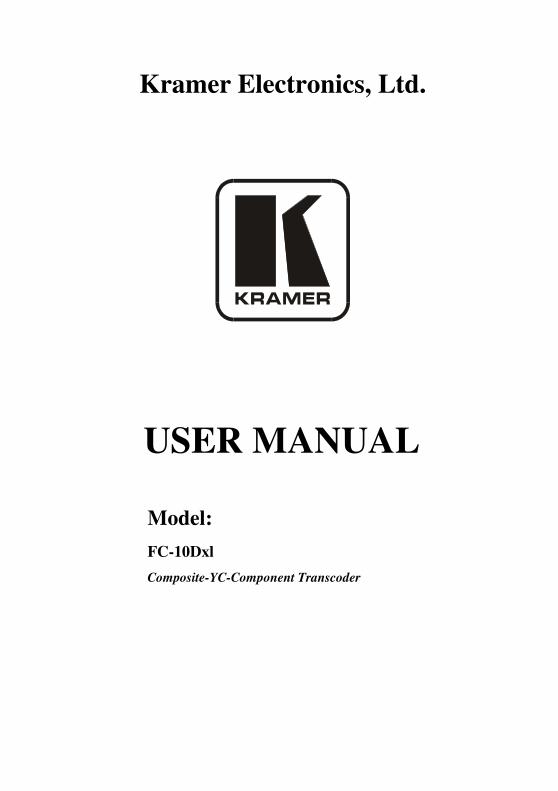
The contact closure remote control pins operate in a similar way to the input selector buttons. Using the contact closure remote control lets you select an input by remote control. To do so, temporarily connect the required input (CV or Y/C) pin on the REMOTE INPUT SELECT terminal block connector to the G (ground) pin, as illustrated in the examples in Figure 3.
DO NOT connect more than one PIN to the G PIN at the same time
To select the CV input, attach PIN CV to the G PIN:
To select the Y/C input, attach PIN Y/C to the G PIN
Figure 3: Connecting the REMOTE INPUT SELECT Connector
6 Technical Specifications
Table 2 includes the technical specifications:
Table 2: Technical Specifications1,2 of the FC-10Dxl
INPUTS: 1 CV on an RCA connector, 1 YC on a 4-pin connector OUTPUTS: 3 RCA connectors: Y/G, B-Y/B/CV and R-Y/R/C, for use as CV, Y/C, RGB3, or
Component (Y/B-Y/R-Y); 1 Y/C on a 4-pin connector BANDWIDTH (-3dB): 5MHz DIFF. GAIN: 0.35% DIFF. PHASE: 0.25 Deg. K-FACTOR: 0.4% S/N RATIO: 66.3dB CROSSTALK (all hostile): <-66dB CONTROLS: Input selector and output format selector pushbuttons POWER SOURCE: 12V DC, 210mA DIMENSIONS: 21.5cm x 16.2cm x 4.4cm (8.46" x 6.38" x 1.73"), W, D, H WEIGHT: 0.3kg (0.67lbs) approx. ACCESSORIES: Power supply (2V) OPTIONS: RK-1 rack kit
1 Specifications are subject to change without notice
2 Specifications are shown for PAL CV input and YC output, unless otherwise stated
3 Defined as RsGsBs (that is, there is sync on all three components of the RGB outputs)
7
LIMITED WARRANTY
WHO IS PROTECTED?
WHAT IS COVERED AND WHAT IS NOT COVERED
WHAT WE WILL PAY FOR AND WHAT WE WILL NOT PAY FOR
HOW YOU CAN GET WARRANTY SERVICE
LIMITATION OF IMPLIED WARRANTIES
EXCLUSION OF DAMAGES
CAUTION!
Kramer Electronics (hereafter ) warrants this product free from defects in material and workmanship under the following terms.
Kramer
HOW LONG IS THE WARRANTYLabor and parts are warranted for seven years from the date of the first customer purchase.
Only the first purchase customer may enforce this warranty.
We will pay labor and material expenses for covered items. We will not pay for the following:
The liability of Kramer for any effective products is limited to the repair or replacement of the product at our option. Kramer shall not be liable for:
This warranty gives you specific legal rights, and you may also have other rights, which vary from place to place. All products returned to Kramer for service must have prior approval. This may be obtained from your dealer.
This equipment has been tested to determine compliance with the requirements of:
EN-50081: "Electromagnetic compatibility (EMC);generic emission standard.
Residential, commercial and light industry"EN-50082: "Electromagnetic compatibility (EMC) generic immunity standard.
Part 1: Residential, commercial and light industry environment".CFR-47: FCC* Rules and Regulations:
Part 15: “Radio frequency devicesSubpart B Unintentional radiators”
Except as below, this warranty covers all defects in material or workmanship in this product. The following are not covered by the warranty:1. Any product which is not distributed by Kramer, or which is not purchased from an authorized Kramer dealer. If you are
uncertain as to whether a dealer is authorized, please contact Kramer at one of the agents listed in the Web site www.kramerelectronics.com.
2. Any product, on which the serial number has been defaced, modified or removed, or on which the WARRANTY VOID TAMPERED sticker has been torn,
3. Damage, deterioration or malfunction resulting from:i) Accident, misuse, abuse, neglect, fire, water, lightning or other acts of natureii) Product modification, or failure to follow instructions supplied with the productiii) Repair or attempted repair by anyone not authorized by Krameriv) Any shipment of the product (claims must be presented to the carrier)v) Removal or installation of the productvi) Any other cause, which does not relate to a product defectvii) Cartons, equipment enclosures, cables or accessories used in conjunction with the product
1. Removal or installations charges.2. Costs of initial technical adjustments (set-up), including adjustment of user controls or programming. These costs are the
responsibility of the Kramer dealer from whom the product was purchased.3. Shipping charges.
1. To obtain service on you product, you must take or ship it prepaid to any authorized Kramer service center.2. Whenever warranty service is required, the original dated invoice (or a copy) must be presented as proof of warranty
coverage, and should be included in any shipment of the product. Please also include in any mailing a contact name, company, address, and a description of the problem(s).
3. For the name of the nearest Kramer authorized service center, consult your authorized dealer.
All implied warranties, including warranties of merchantability and fitness for a particular purpose, are limited in duration to the length of this warranty.
1. Damage to other property caused by defects in this product, damages based upon inconvenience, loss of use of the product, loss of time, commercial loss; or:
2. Any other damages, whether incidental, consequential or otherwise. Some countries may not allow limitations on how long an implied warranty lasts and/or do not allow the exclusion or limitation of incidental or consequential damages, so the above limitations and exclusions may not apply to you.
Servicing the machines can only be done by an authorized Kramer technician. Any user who makes changes or modifications to the unit without the expressed approval of the manufacturer will void user authority to operate the equipment.Use the supplied DC power supply to feed power to the machine.Please use recommended interconnection cables to connect the machine to other components.
IF reattached, removed or otherwise interfered with.
* FCC and CE approved using STP cable (for twisted pair products)
NOTE:
Part 1:

Kramer Electronics, Ltd. Web site: www.kramerelectronics.com
E-mail: [email protected] P/N: 2900-000514 REV 2
For the latest information on our products and a list of Kramer distributors, visit our Web site: www.kramerelectronics.com,
where updates to this user manual may be found. We welcome your questions, comments and feedback.
Caution
Safety Warning: Disconnect the unit from the power supply before opening/servicing.