Embed Size (px)
Citation preview
7/30/2019 FBG inscription.pdf
http://slidepdf.com/reader/full/fbg-inscriptionpdf 1/9
Fiber Bragg gratings inscribed using 800nmfemtosecond laser and a phase mask in single-
and multi-core mid-IR glass fibers
Rui Suo,
1,*
Joris Lousteau,
2
Hongxia Li,
3
Xin Jiang,
2
Kaiming Zhou,
1
Lin Zhang,
1
William N MacPherson,3
Henry T Bookey,3
James S Barton3,
Ajoy K Kar,3
Animesh Jha2
and Ian Bennion1
1Photonics Research Group, Aston University, Birmingham, UK, B47ET 2 Institute for Materials Research, University of Leeds, Clarendon Road, Leeds LS2 9JT, UK
3 Department of Physics, School of Engineering and Physical Sciences, Heriot-Watt University, Edinburgh EH14 4AS,UK
*Corresponding author: [email protected]
Abstract: For the first time, Fiber Bragg grating (FBG) structures havebeen inscribed in single-core passive germanate and three-core passive andactive tellurite glass fibers using 800nm femtosecond ( fs) laser and phasemask technique. With fs peak power intensity in the order of 10
11W/cm
2, the
FBG spectra with 2nd
and 3rd
order resonances at 1540 and 1033nm in thegermanate glass fiber and 2
ndorder resonances at ~1694 and ~1677nm with
strengths up to 14dB in all three cores in the tellurite fiber were observed.Thermal responsivities of the FBGs made in these mid-IR glass fibers were
characterized, showing average temperature responsivity ~20pm/ °C. Strainresponsivities of the FBGs in germanate glass fiber were measured to be1.219pm/ µε.
2009 Optical Society of America
OCIS codes: (320.7140) Ultrafast process in fibers; (060.3735) Fiber Bragg gratings.
References and links
1. S. Shen, A. Jha, X. Liu, M. Naftaly, K. Bindra, H. J. Bookey, and A. K. Kar, “Tellurite glasses forbroadband amplifiers and integrated optics,” J. Am. Ceram. Soc. 85, 1391-1395 (2002).
2. T. Uemura, K. Nishida, M. Sakakida, K. Ichinose, S. Shimoda, and M. Shichiri, “Non-invasive bloodglucose measurement by Fourier transform infrared spectroscopic analysis through the mucous membrane
of the lip: application of a chalcogenide optical fiber system,” Frontiers Med. Biol. Eng. 9, 137-153 (1999).3. J. Mulrooney, J. Clifford, C. Fitzpatrick, and E. Lewis, “Detection of carbon dioxide emissions from a
diesel engine using a mid-infrared optical fibre based sensor,” Sens. Actuators A: Physical. 136, 104-110(2007).
4. K. S. Bindra, H. T. Bookey, A. K. Kar, B. S. Wherrett, X. Liu, and A. Jha, “Nonlinear optical properties of chalcogenide glasses: Observaton of multiphoton absorption,” Appl. Phys. Lett. 79, 1939-1941(2001).
5. A. Mori, H. Masuda, K. Shikano, and M. Shimizu, “Ultra-wide-band tellurite-based fiber Ramanamplifier.” J. Lightwave Technol. 21, 1300-13106 (2003).
6. A. Céreyon, B. Champagnon, V. Martinez, L. Maksimov, O. Yanush, and V. N. Bogdanov, “xPbO-(1-x)GeO2 glasses as potential materials for Raman amplification,” Opt. Mater. 28, 1301-1304 (2006).
7. M. Silva-López, W. N. MacPherson, C. Li, A. J. Moore, J. S. Barton, J. D. C. Jones, D. Zhao, L. Zhang,and I. Bennion, “Transverse load and orientation measurement with multicore fiber Bragg gratings,” Appl.Opt. 44, 6890-6897 (2005).
8. G. M. H. Flockhart, W. N. MacPherson, J. S. Barton, J. D. C. Jones, L. Zhang, and I. Bennion, “Two-axisbend measurement with Bragg gratings in multicore optical fiber,” Opt. Lett. 28, 387-389 (2003).
9. P. Glas, M. Naumann, A. Schirmacher, and Th. Pertsch, “The multicore fiber - a novel design for a diode
pumped fiber laser.” Opt. Commun. 151, 187-195 (1998).10. X. Jiang, J. Lousteau, and A. Jha, “Raw materials purification for the development of high performanceinfrared transmitting germanate glass fibre,” Glass Technology: The European Journal of Glass Science &Technology, Part A in press (2008)
11. J. Lousteau, H. Bookey, X. Jiang, C. Hill, A. Kar, and A. Jha, “Fabrication of multicore tellurite glassoptical fibres,” in Proceedings of IEEE International Conference on Transparent Optical Networks(Institute of Electrical and Electronics Engineers, Rome, 504-509, (2007).
#108667 - $15.00 USD Received 11 Mar 2009; revised 9 Apr 2009; accepted 15 Apr 2009; published 22 Apr 2009
(C) 2009 OSA 27 April 2009 / Vol. 17, No. 9 / OPTICS EXPRESS 7540
7/30/2019 FBG inscription.pdf
http://slidepdf.com/reader/full/fbg-inscriptionpdf 2/9
12. H. T. Bookey, J. Lousteau, A. Jha, N. Gayraud, R. R. Thomson, N. D. Psaila, H. Li, W. N. MacPherson, J.S. Barton, and A. K. Kar, “Multiple rare earth emissions in a multicore tellurite fiber with a single pumpwavelength,” Opt. Express. 15, 17554-17561 (2007).
13. S. J. Mihailov, C. W. Smelser, D. Grobnic, R. B.Walker, P. Lu, H. Ding, and J. Unruh, “Bragg gratingswritten in all-SiO2 and Ge-doped core fibers with 800-nm femtosecond radiation and a phase mask,” J.Lightwave Technol. 22, 94-100 (2004).
14. C. W. Smelser, S. J. Mihailov, D. Grobnic, P. Lu, R. B.Walker, H. Ding, and X. Dai, “Multiple-beaminterference patterns in optical fiber generated with ultrafast pulses and a phase mask,” Opt. Lett. 29, 1458-
1460 (2004).15. C. W. Smelser, D. Grobnic, and S. J. Mihailov, “Generation of pure two-beam interference gratingstructures in an optical fiber with a femtosecond infrared source and a phase mask,” Opt. Lett. 29, 1730-1732 (2004).
16. C. W. Smelser, S. J. Mihailov, and D. Grobnic, “Rouard’s method modeling of type I-IR fiber Bragggratings made using an ultrafast IR laser and a phase mask,” J. Opt. Soc. Am. B. 23, 2011-2017 (2006).
17. C. W. Smelser, S. J. Mihailov, and D. Grobnic, “Impact of index change saturation on the growth behaviorof higher-order type I ultrafast induced fiber Bragg gratings,” J. Opt. Soc. Am. B. 25, 877-883 (2008).
18. C. W. Smelser, S. J. Mihailov, and D. Grobnic, “Formation of Type I-IR and Type II-IR gratings with anultrafast IR laser and a phase mask”, Opt. Express. 13, 5377-5386 (2005).
19. N. M. Dragomir, C. Rollinson, S. A.Wade, A. J. Stevenson, S. F. Collins, G. W. Baxter, P. M. Farrell, andA. Roberts, “Nondestructive imaging of a type I optical fiber Bragg grating,” Opt. Lett. 28, 789–791(2003).
20. X. Shu, K. Sugden, D. Zhao, F. Floreani, L. Zhang and I. Bennion, “Complex growth behaviour of hybrid-type fibre Bragg gratings,” Electron. Lett. 39, 274-276 (2003).
21. S. S. Bayya, G. D. Chin, J. S. Sanghera, and I. D. Aggarwal, “Germanate glass as a window for high energylaser systems,” Opt. Express 14, 11687-11693 (2006).
22. H. Li, J. Lousteau, W. N. MacPherson, X. Jiang, H. T. Bookey, J. S. Barton, A. Jha, and A. K. Kar,“Thermal sensitivity of tellurite and germinate optical fibers,” Opt.Express. 15, 8857-8863 (2007).
23. A. I. Rabukhin, “Concentration dependences of elastooptic coefficients of germanate glasses containinglead and bismuth oxides,” Glass and Ceramics. 37, 87-90 (1995).
24. A. K. Ghatak and K. Thyagarajan, Optical Electronics. (Cambridge University Press), Chap.16, 1989, p503
25. A. EL-Adawy and R. EL-Mallawany, “Elastic modulus of tellurite glasses,” J. Mater. Sci. Lett. 15, 2065-2067 (1996).
1. Introduction
Germanate and tellurite glass fibers have attracted considerable attention to be explored forfiber devices in near and mid-IR regions. Their high refractive index and optical nonlinearity,resistance to corrosion, low melting temperature and good transmission properties from thevisible to mid-IR region (0.35-6µm) [1] make them promising fiber hosts for bio/chemical andgas sensing [2-3], nonlinear optical signal processing [4] and optical amplifier and laser [5-6]
devices. In recent years, we have also seen that there are increasingly reports for multi-corefibers (MCFs). MCFs can offer new device designs such as arrayed fiber sensors for load andbend measurement with direction recognition and temperature compensation capability [7-8]and arrayed fiber lasers and amplifiers which can scale up output powers [9]. Very recently,germanate and tellurite glass fibers with single- and three-core have been fabricated [10-11],and more significantly, the three-core tellurite glass fiber has been actively doped withHo
3+ /Tm
3+ /Yb
3+, Er
3+ /Ce
3+, and Tm
3+ /Yb
3+respectively in each core and the emissions from
the visible to mid-IR have been observed [12].Single- and multi-core passive and active germanate and tellurite glass fibers represent a
new class fiber host for devices which will extend photonics applications to mid-IR range,which is in increasing demands. Fiber Bragg grating (FBG) structures have been proven asone of the most functional in-fiber devices and vastly produced in silicate fibers by UV-inscription for countless laser and sensor applications. However, because germanate andtellurite fibers absorb UV greatly, FBG structures cannot be produced in such fibers by UV-inscription. In recent years, femtosecond ( fs) lasers have been developed for laser machiningand microstructuring in a variety of glass fibers and planar substrates. A number of papershave been reported on fabrication of FBGs and long-period gratings in optical fibers and alsoon the photosensitivity mechanism using 800 nm fs lasers [13-18].
#108667 - $15.00 USD Received 11 Mar 2009; revised 9 Apr 2009; accepted 15 Apr 2009; published 22 Apr 2009
(C) 2009 OSA 27 April 2009 / Vol. 17, No. 9 / OPTICS EXPRESS 7541
7/30/2019 FBG inscription.pdf
http://slidepdf.com/reader/full/fbg-inscriptionpdf 3/9
In this paper, we demonstrate for the first time the fabrication of FBGs in single-corepassive germanate and three-core passive and active tellurite glass fibers by 800 nm fs-inscription. Using a 1697.33 nm period phase mask, the 2
ndorder FBG resonances with
strength up to ~14 dB have been achieved in these mid-IR fibers and their thermal and strainresponsivities have been characterized.
2. Fabrication and characteristics of germanate and tellurite glass fibers
The used germanate and tellurite fibers were drawn from glass compositions (mol%):55GeO2-30PbO-11Na2O-4Ga2O3 (GPNG) and 79TeO2-14ZnO-7Na2O (TZN), respectively forpassive fibers, whereas for the active fiber the composition was 80TeO2-10ZnO-10Na2O. Themethods for fiber fabrication are described elsewhere [10-11]. The GPNG fiber has anundoped single-core with a diameter of ~8 µm surrounded by a cladding of ~126 µm diameter.The refractive indices of the core and cladding are 1.8622 and 1.8505 at 633 nm, respectively.The passive TZN fiber has three cores with diameters of ~12 µm and arranged equilaterallyfrom the center with a separation of ~35 µm between each core, and surrounded by a claddingof ~130 µm diameter. The refractive indices of the TZN fiber core and cladding are measuredas 2.0475 and 2.0224 at 633 nm, respectively. The active three-core TZN fiber has a similarform to the passive one, but with smaller core diameters, ~6 µm, and all three cores weredoped with Er
3+ /Ce
3+. However, it has a double-clad structure with the inner and outer
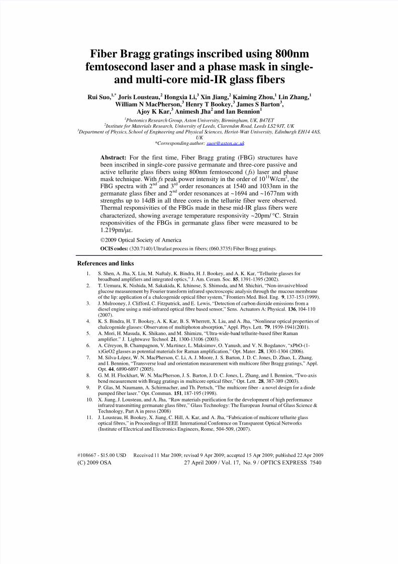
cladding diameters of ~68 and ~120 µm with refractive indices of 2.0224 and ~1.9900 at 633nm, respectively. The cross section images of the single-core GPNG and three-core passiveand active TZN fibers are shown in Figs. 1(a)-1(c). Both GPNG and TZN fibers have muchlower softening point for glass fabrication at approximately 480 °C and 320 °C, respectively,which are substantially lower than that (~1200 °C) of silica glass.
Fig. 1. Microscopy images of the cross-sections of (a) GPNG single-core fiber, (b) TZNpassive and (c) active three-core fibers. Note: the D-shape-like end images are attributed tocleaving defects, as the fibres are not standard and fragile to achieve nice-finish cleaving.
3. FBG structures inscribed using femtosecond laser and phase mask
The FBG structures were produced in the GPNG and TZN fibers using fs-inscription througha custom-designed phase mask with a period of 1697.33 nm. Because of high refractiveindices of the GPNG and TZN fibers, the phase mask was aiming to fs-inscribing 2
ndorder
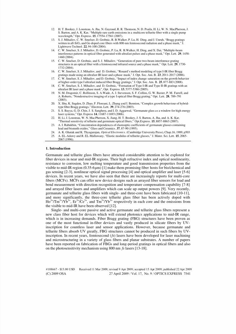
FBGs around 1500-1800 nm. The 800 nm fs laser power was from an amplified Ti:sapphiresystem with a repetition rate of 1kHz and a maximum output energy of ~1 mJ. The pulseduration measured by an autocorrelator was <120 fs. The output beam with a radius of 5 mmwas focused in y-axis by a cylindrical lens of 30 mm focal length and through the phase mask
to the fiber core. Due to the focusing effect of the high refractive index of the cladding, thelaser beam was highly focused. Hence the width of fs-inscribed grating structure along x-axis,as shown in Fig. 2(b), is merely ~2 µm. Such a thin-layer of FBG structure would not give ahigh reflectivity and also in the experiment it was easy to miss the core region. To ensuremaximum coverage of fs-inscription in the core region, the incident beam was scanned alongthe x-axis from -30 to 30 µm with an incremental step of 2 µm for the single-core GPNG fiber
#108667 - $15.00 USD Received 11 Mar 2009; revised 9 Apr 2009; accepted 15 Apr 2009; published 22 Apr 2009
(C) 2009 OSA 27 April 2009 / Vol. 17, No. 9 / OPTICS EXPRESS 7542
7/30/2019 FBG inscription.pdf
http://slidepdf.com/reader/full/fbg-inscriptionpdf 4/9
and from -50 to 50 µm for the three-core TZN fibers. After each shift, the translation stagewas paused for 3 min letting the fs-exposing the focused fibre position. In order to eliminatethe phase error which might be induced by the multi-scan along x-axis, the fibre was placedvery close to the phase mask in the y-axis direction. It was noted that the fs power level iscritical for inscribing FBG structure in the core without burning the fiber. Via systematicaltests, we identified critical fs energy levels of ~22 and ~14 µJ to be suitable for inscribingFBGs in the GPNG and TZN fibers.
Fig. 2. Schematic diagram of FBG inscription system using fs laser and phase mask with a TZNMCF mounted. The x axis in (b) is parallel to the phase mask and perpendicular to the grooves;and the y axis is normal to the phase mask.
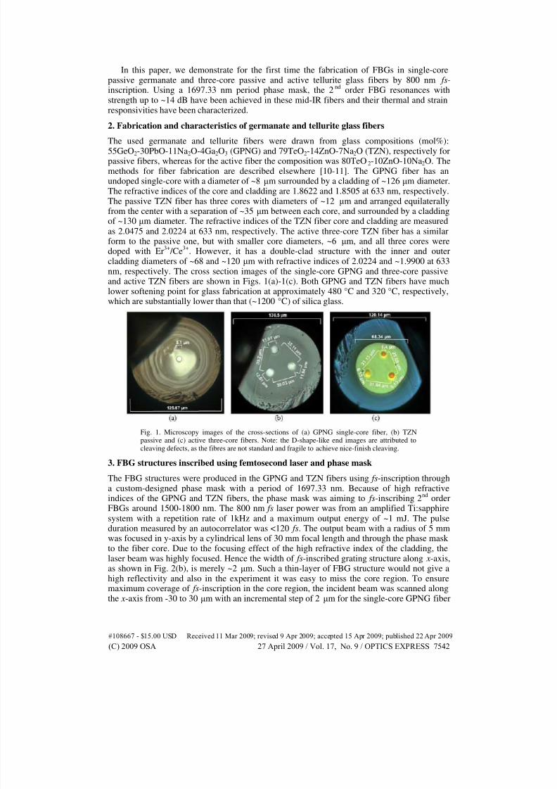
After fs-inscription, we first examined the FBG fringe structures under the microscope.For all inscribed GPNG and TZN fiber samples, we have seen clear fringe structures. Fig. 3(a)shows the top view (from the laser incident direction) image of an inscribed three-core TZNfiber and we can see all the three cores are fully covered by the continuous fringes. It is notedthat, the different sizes of the imaged cores are due to different focus position of themicroscope. Fig. 3(b) exhibits the side view image, the grating structure covering the almostthe whole section depicts a typical three beams interference pattern. We measured the fringespace from the microscope image is 1.687 µm, which is close to the phase mask period,instead of a half of it. This is attributed to the Talbot effect [19] induced by the group-velocity
walk-off of phase mask order pairs [14].
Fig. 3. Microscopy images of grating structure from (a) the top view and (b) side view of theTZN passive fiber. In both (a) and (b), the periods of the structures are measured as 1.687 µm.
4. Transmission properties
A super continuum broadband light source from Koheras with the output wavelength up to1800nm was employed to examine the grating spectra of the fabricated FBGs in single-core
#108667 - $15.00 USD Received 11 Mar 2009; revised 9 Apr 2009; accepted 15 Apr 2009; published 22 Apr 2009
(C) 2009 OSA 27 April 2009 / Vol. 17, No. 9 / OPTICS EXPRESS 7543
7/30/2019 FBG inscription.pdf
http://slidepdf.com/reader/full/fbg-inscriptionpdf 5/9
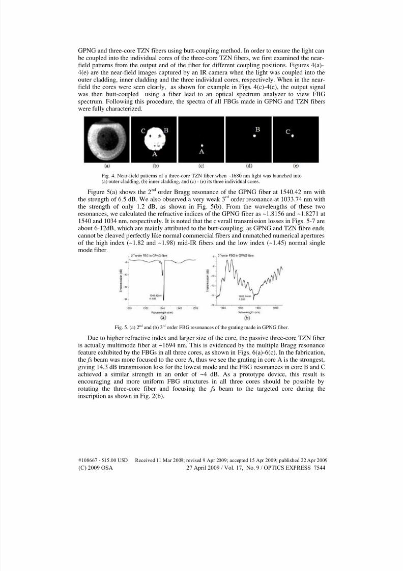
GPNG and three-core TZN fibers using butt-coupling method. In order to ensure the light canbe coupled into the individual cores of the three-core TZN fibers, we first examined the near-field patterns from the output end of the fiber for different coupling positions. Figures 4(a)-4(e) are the near-field images captured by an IR camera when the light was coupled into theouter cladding, inner cladding and the three individual cores, respectively. When in the near-field the cores were seen clearly, as shown for example in Figs. 4(c)-4(e), the output signalwas then butt-coupled using a fiber lead to an optical spectrum analyzer to view FBG
spectrum. Following this procedure, the spectra of all FBGs made in GPNG and TZN fiberswere fully characterized.
Fig. 4. Near-field patterns of a three-core TZN fiber when ~1680 nm light was launched into(a) outer cladding, (b) inner cladding, and (c) - (e) its three individual cores.
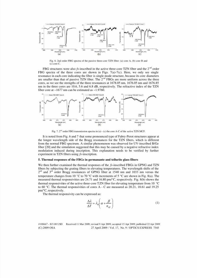
Figure 5(a) shows the 2nd
order Bragg resonance of the GPNG fiber at 1540.42 nm with
the strength of 6.5 dB. We also observed a very weak 3rd
order resonance at 1033.74 nm withthe strength of only 1.2 dB, as shown in Fig. 5(b). From the wavelengths of these tworesonances, we calculated the refractive indices of the GPNG fiber as ~1.8156 and ~1.8271 at1540 and 1034 nm, respectively. It is noted that the overall transmission losses in Figs. 5-7 areabout 6-12dB, which are mainly attributed to the butt-coupling, as GPNG and TZN fibre endscannot be cleaved perfectly like normal commercial fibers and unmatched numerical aperturesof the high index (~1.82 and ~1.98) mid-IR fibers and the low index (~1.45) normal singlemode fiber.
Fig. 5. (a) 2nd and (b) 3rd order FBG resonances of the grating made in GPNG fiber.
Due to higher refractive index and larger size of the core, the passive three-core TZN fiberis actually multimode fiber at ~1694 nm. This is evidenced by the multiple Bragg resonancefeature exhibited by the FBGs in all three cores, as shown in Figs. 6(a)-6(c). In the fabrication,the fs beam was more focused to the core A, thus we see the grating in core A is the strongest,giving 14.3 dB transmission loss for the lowest mode and the FBG resonances in core B and Cachieved a similar strength in an order of ~4 dB. As a prototype device, this result isencouraging and more uniform FBG structures in all three cores should be possible byrotating the three-core fiber and focusing the fs beam to the targeted core during theinscription as shown in Fig. 2(b).
#108667 - $15.00 USD Received 11 Mar 2009; revised 9 Apr 2009; accepted 15 Apr 2009; published 22 Apr 2009
(C) 2009 OSA 27 April 2009 / Vol. 17, No. 9 / OPTICS EXPRESS 7544
7/30/2019 FBG inscription.pdf
http://slidepdf.com/reader/full/fbg-inscriptionpdf 6/9
Fig. 6. 2nd order FBG spectra of the passive three-core TZN fiber: (a) core A, (b) core B and(c) core C.
FBG structures were also fs-inscribed in the active three-core TZN fiber and the 2nd
orderFBG spectra of the three cores are shown in Figs. 7(a)-7(c). Here, we only see singleresonance in each core indicating the fiber is single mode structure, because its core diametersare smaller than that of passive TZN fiber. The 2
ndFBGs are more uniform across the three
cores, as we see the strengths of the three resonances at 1678.05 nm, 1676.05 nm and 1676.85nm in the three cores are 10.6, 5.6 and 6.8 dB, respectively. The refractive index of the TZNfiber core at ~1677 nm can be estimated as ~1.9760.
Fig. 7. 2nd order FBG transmission spectra in (a) - (c) the core A-C of the active TZN MCF.
It is noted from Fig. 6 and 7 that some pronounced type of Fabry-Perot structures appear atthe longer wavelength side of the Bragg resonances for the TZN fibers, which is differentfrom the normal FBG spectrum. A similar phenomenon was observed for UV-inscribed B/Ge
fiber [20] and the simulation suggested that this may be caused by a negative refractive indexmodulation induced during inscription. This explanation needs to be verified by furtherexperiment in TZN fibers using fs-inscription.
5. Thermal responses of the FBGs in germanante and tellurite glass fibers
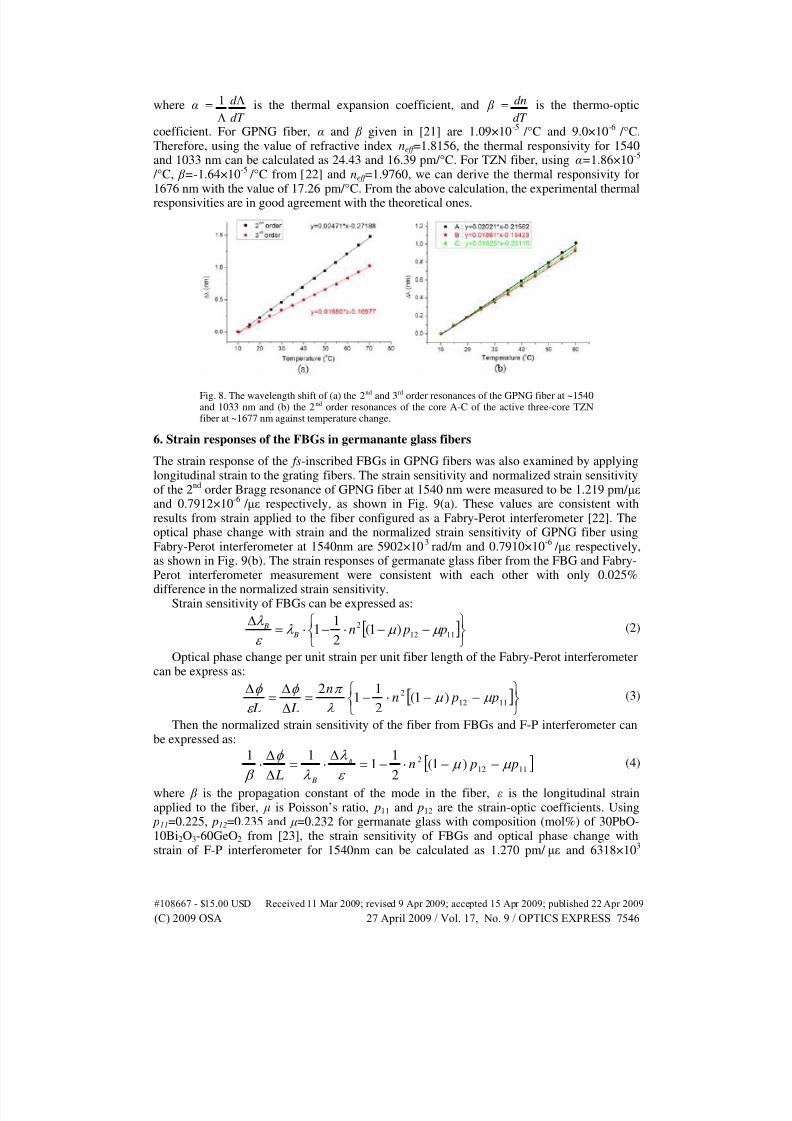
We then further examined the thermal responses of the fs-inscribed FBGs in GPNG and TZNfibers by subjecting the grating fibers to elevating temperatures. The wavelength shifts of the2
ndand 3
rdorder Bragg resonances of GPNG fiber at 1540 nm and 1033 nm versus the
temperature changes from 10 °C to 70 °C with increments of 5 °C are shown in Fig. 8(a). Themeasured thermal responsivities are 24.71 and 16.80 pm/°C, respectively. Fig. 8(b) shows the
thermal responsivities of the active three-core TZN fiber for elevating temperature from 10 °Cto 60 °C. The thermal responsivities of cores A - C are measured as 20.21, 18.61 and 19.25pm/°C, respectively.
The thermal responsivity can be expressed as:
+=
∆
∆
eff
BnT
β α λ
λ (1)
#108667 - $15.00 USD Received 11 Mar 2009; revised 9 Apr 2009; accepted 15 Apr 2009; published 22 Apr 2009
(C) 2009 OSA 27 April 2009 / Vol. 17, No. 9 / OPTICS EXPRESS 7545
7/30/2019 FBG inscription.pdf
http://slidepdf.com/reader/full/fbg-inscriptionpdf 7/9
where α =dT
d Λ
Λ
1 is the thermal expansion coefficient, and β =dT
dn is the thermo-optic
coefficient. For GPNG fiber, α and β given in [21] are 1.09×10⁻⁵
/°C and 9.0×10⁻⁶
/°C.Therefore, using the value of refractive index neff =1.8156, the thermal responsivity for 1540and 1033 nm can be calculated as 24.43 and 16.39 pm/°C. For TZN fiber, using α=1.86×10
-5
/°C, β =-1.64×10⁻⁵ /°C from [22] and neff =1.9760, we can derive the thermal responsivity for
1676 nm with the value of 17.26 pm/°C. From the above calculation, the experimental thermalresponsivities are in good agreement with the theoretical ones.
Fig. 8. The wavelength shift of (a) the 2nd and 3rd order resonances of the GPNG fiber at ~1540and 1033 nm and (b) the 2nd order resonances of the core A-C of the active three-core TZNfiber at ~1677 nm against temperature change.
6. Strain responses of the FBGs in germanante glass fibers
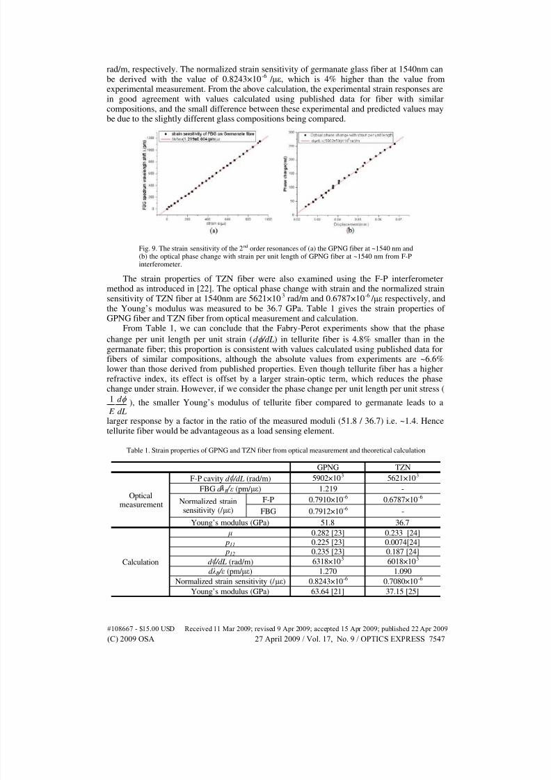
The strain response of the fs-inscribed FBGs in GPNG fibers was also examined by applyinglongitudinal strain to the grating fibers. The strain sensitivity and normalized strain sensitivityof the 2
ndorder Bragg resonance of GPNG fiber at 1540 nm were measured to be 1.219 pm/ µε
and 0.7912×10⁻⁶
/ µε respectively, as shown in Fig. 9(a). These values are consistent withresults from strain applied to the fiber configured as a Fabry-Perot interferometer [22]. Theoptical phase change with strain and the normalized strain sensitivity of GPNG fiber usingFabry-Perot interferometer at 1540nm are 5902×10
3rad/m and 0.7910×10
-6 / µε respectively,
as shown in Fig. 9(b). The strain responses of germanate glass fiber from the FBG and Fabry-Perot interferometer measurement were consistent with each other with only 0.025%
difference in the normalized strain sensitivity.Strain sensitivity of FBGs can be expressed as:
[ ]
−−⋅−⋅=∆
1112
2 )1(2
11 p pn
B B µ µ λ ε
λ (2)
Optical phase change per unit strain per unit fiber length of the Fabry-Perot interferometercan be express as:
[ ]
−−⋅−=∆
∆=
∆1112
2 )1(2
11
2 p pn
n
L Lµ µ
λ
π φ
ε
φ (3)
Then the normalized strain sensitivity of the fiber from FBGs and F-P interferometer canbe expressed as:
[ ]1112
2 )1(2
11
11 p pn
L
B
B
µ µ ε
λ
λ
φ
β −−⋅−=
∆⋅=
∆
∆⋅ (4)
where β is the propagation constant of the mode in the fiber, ε is the longitudinal strainapplied to the fiber, µ is Poisson’s ratio, p11 and p12 are the strain-optic coefficients. Using p11=0.225, p12=0.235 and µ=0.232 for germanate glass with composition (mol%) of 30PbO-10Bi2O3-60GeO2 from [23], the strain sensitivity of FBGs and optical phase change withstrain of F-P interferometer for 1540nm can be calculated as 1.270 pm/ µε and 6318×10
3
#108667 - $15.00 USD Received 11 Mar 2009; revised 9 Apr 2009; accepted 15 Apr 2009; published 22 Apr 2009
(C) 2009 OSA 27 April 2009 / Vol. 17, No. 9 / OPTICS EXPRESS 7546
7/30/2019 FBG inscription.pdf
http://slidepdf.com/reader/full/fbg-inscriptionpdf 8/9
rad/m, respectively. The normalized strain sensitivity of germanate glass fiber at 1540nm canbe derived with the value of 0.8243×10
-6 / µε, which is 4% higher than the value from
experimental measurement. From the above calculation, the experimental strain responses arein good agreement with values calculated using published data for fiber with similarcompositions, and the small difference between these experimental and predicted values maybe due to the slightly different glass compositions being compared.
Fig. 9. The strain sensitivity of the 2nd order resonances of (a) the GPNG fiber at ~1540 nm and(b) the optical phase change with strain per unit length of GPNG fiber at ~1540 nm from F-Pinterferometer.
The strain properties of TZN fiber were also examined using the F-P interferometermethod as introduced in [22]. The optical phase change with strain and the normalized strainsensitivity of TZN fiber at 1540nm are 5621×10
3rad/m and 0.6787×10
-6 / µε respectively, and
the Young’s modulus was measured to be 36.7 GPa. Table 1 gives the strain properties of GPNG fiber and TZN fiber from optical measurement and calculation.
From Table 1, we can conclude that the Fabry-Perot experiments show that the phase
change per unit length per unit strain (d φ /dL) in tellurite fiber is 4.8% smaller than in thegermanate fiber; this proportion is consistent with values calculated using published data forfibers of similar compositions, although the absolute values from experiments are ~6.6%lower than those derived from published properties. Even though tellurite fiber has a higherrefractive index, its effect is offset by a larger strain-optic term, which reduces the phasechange under strain. However, if we consider the phase change per unit length per unit stress (
dL
d
E
φ 1 ), the smaller Young’s modulus of tellurite fiber compared to germanate leads to a
larger response by a factor in the ratio of the measured moduli (51.8 / 36.7) i.e. ~1.4. Hencetellurite fiber would be advantageous as a load sensing element.
Table 1. Strain properties of GPNG and TZN fiber from optical measurement and theoretical calculation
GPNG TZN
Opticalmeasurement
F-P cavity d /dL (rad/m) 5902×103 5621×103
FBG d B ε (pm/ µε) 1.219 -
Normalized strainsensitivity (/ µε)
F-P 0.7910×10⁻⁶ 0.6787×10⁻⁶
FBG 0.7912×10⁻⁶ -
Young’s modulus (GPa) 51.8 36.7
Calculation
µ 0.282 [23] 0.233 [24]
p11
0.225 [23] 0.0074[24]
p12 0.235 [23] 0.187 [24]
d /dL (rad/m) 6318×103 6018×103
d λ B / ε (pm/ µε) 1.270 1.090
Normalized strain sensitivity (/ µε) 0.8243×10⁻⁶ 0.7080×10⁻⁶
Young’s modulus (GPa) 63.64 [21] 37.15 [25]
#108667 - $15.00 USD Received 11 Mar 2009; revised 9 Apr 2009; accepted 15 Apr 2009; published 22 Apr 2009
(C) 2009 OSA 27 April 2009 / Vol. 17, No. 9 / OPTICS EXPRESS 7547
7/30/2019 FBG inscription.pdf
http://slidepdf.com/reader/full/fbg-inscriptionpdf 9/9
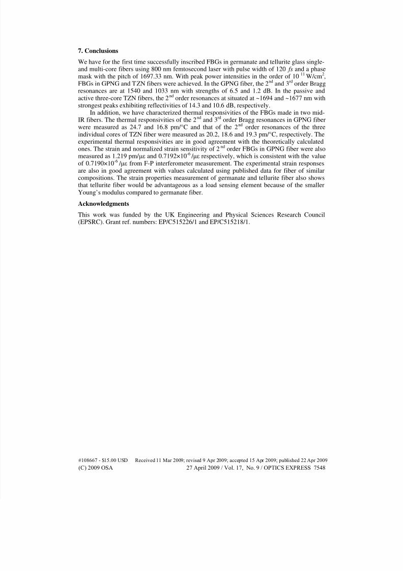
7. Conclusions
We have for the first time successfully inscribed FBGs in germanate and tellurite glass single-and multi-core fibers using 800 nm femtosecond laser with pulse width of 120 fs and a phasemask with the pitch of 1697.33 nm. With peak power intensities in the order of 10
11W/cm
2,
FBGs in GPNG and TZN fibers were achieved. In the GPNG fiber, the 2nd
and 3rd
order Braggresonances are at 1540 and 1033 nm with strengths of 6.5 and 1.2 dB. In the passive and
active three-core TZN fibers, the 2nd
order resonances at situated at ~1694 and ~1677 nm withstrongest peaks exhibiting reflectivities of 14.3 and 10.6 dB, respectively. In addition, we have characterized thermal responsivities of the FBGs made in two mid-
IR fibers. The thermal responsivities of the 2nd
and 3rd
order Bragg resonances in GPNG fiberwere measured as 24.7 and 16.8 pm/°C and that of the 2
ndorder resonances of the three
individual cores of TZN fiber were measured as 20.2, 18.6 and 19.3 pm/°C, respectively. Theexperimental thermal responsivities are in good agreement with the theoretically calculatedones. The strain and normalized strain sensitivity of 2
ndorder FBGs in GPNG fiber were also
measured as 1.219 pm/ µε and 0.7192×10⁻⁶ / µε respectively, which is consistent with the value
of 0.7190×10⁻⁶
/ µε from F-P interferometer measurement. The experimental strain responsesare also in good agreement with values calculated using published data for fiber of similarcompositions. The strain properties measurement of germanate and tellurite fiber also showsthat tellurite fiber would be advantageous as a load sensing element because of the smallerYoung’s modulus compared to germanate fiber.
Acknowledgments
This work was funded by the UK Engineering and Physical Sciences Research Council(EPSRC). Grant ref. numbers: EP/C515226/1 and EP/C515218/1.
#108667 - $15.00 USD Received 11 Mar 2009; revised 9 Apr 2009; accepted 15 Apr 2009; published 22 Apr 2009
(C) 2009 OSA 27 April 2009 / Vol. 17, No. 9 / OPTICS EXPRESS 7548

![Corrosion Resistant FBG-Based Quasi-Distributed Sensor for ... · Corrosion Resistant FBG-Based Quasi-Distributed ... [9,10]. For their particular ... The paper final remarks are](https://img.pdfslide.us/doc/110x75/5bf86f5f09d3f2f4078ba711/corrosion-resistant-fbg-based-quasi-distributed-sensor-for-corrosion-resistant.jpg)


![Application of Multiplexed FBG and PZT Impedance · FBG based sensors for sensing applications in civil and structural engineering [7-9]. FBG sensors offer a wide number of advantages](https://img.pdfslide.us/doc/110x75/5f0c25797e708231d433f797/application-of-multiplexed-fbg-and-pzt-impedance-fbg-based-sensors-for-sensing-applications.jpg)