Embed Size (px)
Citation preview
r AD-AIOl 374 ROYAL AIRCRAFT ESTABLISHMENT FARNBOROUBH (ENGLAND) F/B 10/1ADAPTATION OF A TURBINE TEST FACILITY TO HIGH-TEMPERATURE RESEA--ETC(U)DEC 80 J FRANCOIS,.Y LE SOT, J MICHARD
UNCLASSIFIED RAE-LIWARY TRANS-2064 DRIC-GR-78650 N
mh~hEhh~iEI fl...flf~.l.. lfff
- .v3R78650UNLIMITED -'Trans 206400
N
ROYAL AIRCRAFT ESTABLISHMENT
Library Translation 2064: . JUL 1 ' 1981
December 1980
ADAPTATION OF A TURBINETEST FACILITY TO
HIGH-TEMPERATURE RESEARCH
by
J. Francois,
Y. Le Bot,J. Michard,P. Deguest
r..
Procurement Executive, Ministry of Defence
Farnborough, Hants
UNLIMIT

Translations in this series are available
from:
THE R.A.E. LIBRARY
Q.4 BUILDING
R.A.E. FARNBOROUGHHANTS
New translations are announced monthly in:
"LIST OF R.A.E. TECHNICAL REPORTS,
TRANSLATIONS and BIBLIOGRAPHIES"
I
4'
UDC 621.452.32 621.45.018 621.45.038 : 536.45
AA
ROYAL AI RCRAFT ESTABLISHMENT
Library Translation 2064
l)Received for printing 19 De 0
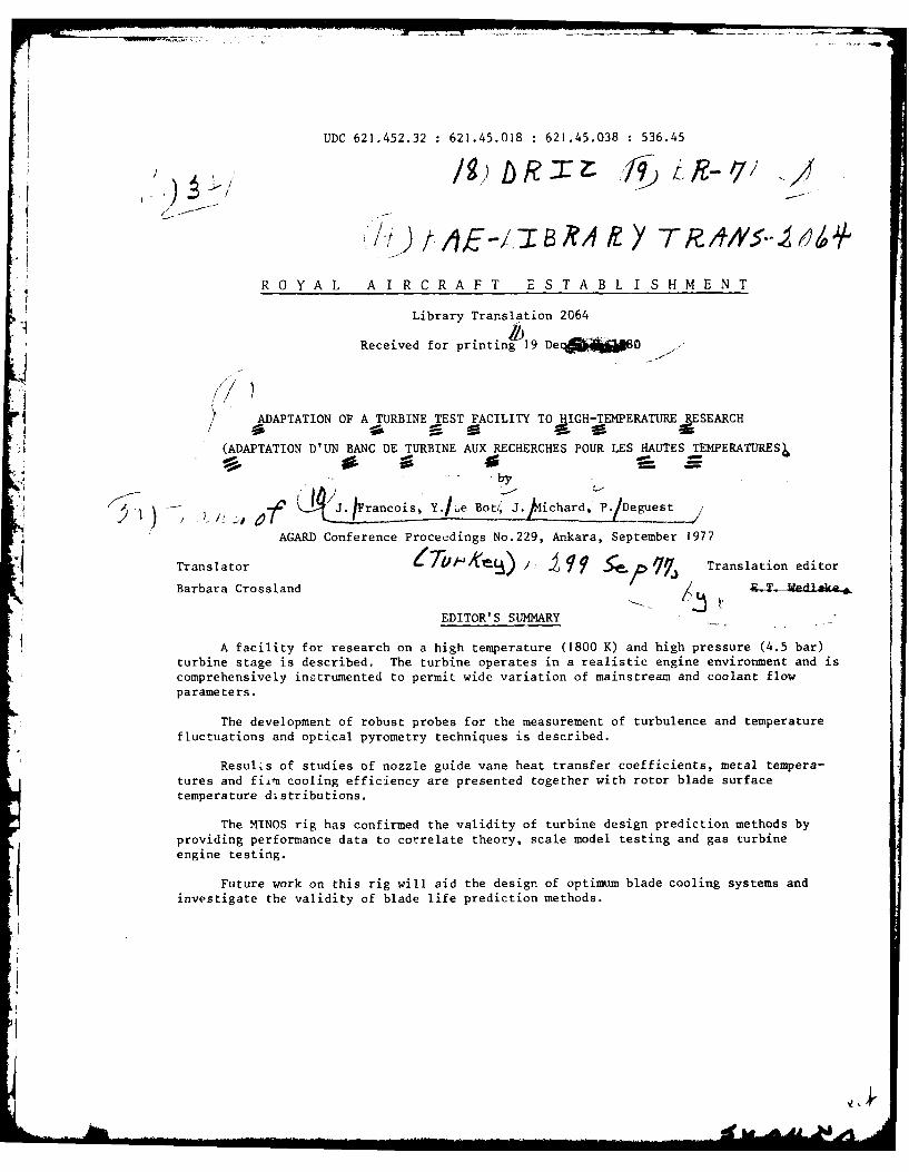
ADAPTATION OF A TURBINE TEST FACILITY TO JIGH-TEMPERATURE RESEARCH
(ADAPTATION D'UN BANC DE TURBINE AUX RECHERCHES POUR LES HAUTES TEMPERATURES-- j
40by
): .v) - 2;. /:' :, a7 4 J.Francois, Y.l..e Bo/ .ih~,P/eetj
AGARD Conference Proceedings No.229, Ankara, September 1977
Translator _. ?9 S p q Translation editor
Barbara Crossland , .- WedL1ak&4a .
EDITOR'S SUMMARY
A facility for research on a high temperature (1800 K) and high pressure (4.5 bar)turbine stage is described. The turbine operates in a realistic engine environment and iscomprehensively instrumented to permit wide variation of mainstream and coolant flowparameters.
The development of robust probes for the measurement of turbulence and temperature
fluctuations and optical pyrometry techniques is described.
ResulLs of studies of nozzle guide vane heat transfer coefficients, metal tempera-tures and fiim cooling efficiency are presented together with rotor blade surfacetemperature distributions.
The MINOS rig has confirmed the validity of turbine design prediction methods by
providing performance data to correlate theory, scale model testing and gas turbineengine testing.
Future work on this rig will aid the design of optimum blade cooling systems andinvestigate the validity of blade life prediction methods.
......."" liHI~rlIilIV d a lt4 4-
2
LIST OF CONTENTS
Page
I INTRODUCTION 3
2 ROLE OF MINOS IN THE STUDY OF HIGH-TEMPERATURE TURBINES 3
3 OBJECTIVES 4
4 MEASUREMENT TECHNIQUES 5
4.1 Characterisation of the non-steady components of flow 5
4.1.1 Pressure fluctuations; aerodynamic turbulence 5
4.1.2 Flow temperature fluctuations 6
4.2 Analysis of rotor blade wakes 6
4.3 Determination of nozzle guide vane heat transfer coefficients 6
4.4 Measuring rotor blade surface temperatures - optical pyrometry 7
4.5 Measurement of heat flux 7
4.6 Experimental study of film cooling 8
5 TECHNOLOGICAL CONCEPT 8
5.1 Test objective constraints (Fig 4) 9
5.2 Principle technological choices 9
6 THE MINOS TURBINE TEST FACILITY 9
6.1 The CEPr turbine test facility 9
6.1.1 History 10
6.1.2 Description of the test installation 10
6.1.3 Capacity of instrumentation system 10
6.2 Test procedure 10
6.3 Data acquisition and processing for MINOS I
7 EXAMPLES OF RESULTS 12
7.1 Pressure fluctuations - turbulence 12
7.2 Nozzle guide vane heat transfer coefficients 12
7.3 Optical pyrometry on rotor blades 13
7.4 Cooling the platforms of the HP nozzle guide vanes 13
8 CONCLUSIONS 13
DISCUSSION 14
Table 1 15
References Accession For 16
Illustrations NTIS 'I, Figures 1-11
DTIC T7 F1
Justii': -- . .
By--Dist-
Av ".
Dist
-- I
3,
I INTRODUCTION
Modern turbojet engines are characterised by elevated temperatures, accompanied by
-levated turbine inlet pressures, in order to reduce their specific fuel consumption. InI! parallel, one demands of their components, and particularly of the turbine, higher work
In order to achieve these objectives, it was necessary to develop cooling techniques,
firstly by improving internal convection and then by recourse to film cooling.
3 The increase in pressure levels, which results in an increase in heat transfer, has
made the blades more sensitive to fatigue problems. Their behaviour has thus become more
and more a local temperature problem and no longer a mean temperature one.
A detailed knowledge of external conditions, heat transfer coefficients and
* temperatures, is therefore now of prime importance. The influence of the engine environ-
ment then becomes significant; pressure heterogeneities, temperature heterogeneities, the
level of turbulence, wakes and rotational effects can affect heat transfer coefficients
and the efficiency of film cooling.
The output of the turbine installed in an engine can also be greatly affected by
the engine environment; coolant discharge from the blades or platforms, leakages, clear-*1 ances and wakes can degrade it to a marked degree.
For this reason, having developed prediction methods and laboratory model tests in
the fields of study concerned, it became apparent that a test method should be conceived
which reproduced as closely as possible the environmental conditions of the engine,
whilst enabling high quality measurements to be carried out.
The aim is not only to check the performance of the blading and to evaluate its
efficiency under conditions close to those of the engine, it is, above all, to character-
ise these operating conditions in order to understand the influence of the different
parameters and to validate the numerical prediction methods.
It is with these objectives in mind that government agencies (Direction des
Recherches et Moyens d'Essais, in association with the Direction Technique des
Constructions A~ronautiques) have brought an engine company, SNEGMA, a research organisa-
tion, ONERA, and a specialised test centre, CEPr, into the MINOS project (Montage Inter
ONERA-SNECMA).
2 ROLE OF MINOS IN THE STUDY OF HIGH-TEMPERATURE TURBINES
The detailed measurements which are desirable for refined analysis of the perform-
ance of the different components of a turbine are generally impossible to obtain on a
test-engine, due to their compactness and to the severe environmental conditions
encountered (elevated temperature and pressure levels, vibrations). Moreover, the con-
flicting requirements of different disciplines (aerodynamic, thermal, metallurgical,
mechanical) frequently make it impossible to gather results other than those which are
too universal to be readily transposed to another type of turbine.
4
Therefore, the validation of design prediction methods and the estimation of prototype
performance, based on the results of l'boratory scudies, requires the specification of an
experimental rig intermediate between static model thermal test rigs, and engines proper.
This experimental rig must include sufficiently flexible and comprehensive operational
control systems to permit independent variation of the parameters influencing the pheno-
mena to be analysed in an environment comparable with that encountered in engines.
Furthermore, its instrumentation system must be sufficiently comprehensive to enable
measurements to be made which are as detailed as those available from model test rigs.
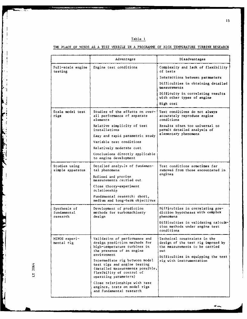
MINOS has been defined to meet these objectives. Its place as a test vehicle in the
study of high-temperature turbines is described in Table I. The key position which it
occupies in relation to engine testing, to model tests, and to studies on simple rigs
designed for fundamental research, is clearly shown in this table. Results obtained using
MINOS, should assist in specifying the direction of model test rig programmes and con-
versely will show the complementary nature of these two types of installation.
3 OBJECTIVES
The general objective of MINOS, which is the study of all the parameters influencing
the performance and behaviour of Lhe blades of a cooled turbine will be achieved by means
of the following steps:
- verification of satisfactory aerodynamic operation;
- characterisation of the environment: measurement of turbulence level, measurement
of temperature distribution,wake analysis;
- study of heat transfer coefficients;
- study of the efficiency of pfotective films;
- thermal fatigud tests;
- tests on blades capable of withstanding high temperatures;
- study of particular technical problems, platforms, shroud rings, abradable
materials ...
The verification of good aerodynamic operation is important; thermal results cannot
be correctly interpreted without a satisfactory knowledge of aerofoil velocity distribu-
tions.
The characterisation of the environment will make it possible to evaluate the
differences between engines and static test rigs and will be carried out in the different
planes of the turbine.
The study of heat transfer coefficients and film cooling effectiveness will be
carried out using the same methods of measurement and thp same blades for both the static
tests and for MINOS. Initially, blades will be tested having simple films at the leading
edge, either on the suction surface or on the pressurp surface; then combinations of these
films will be tried. Both thermal efficiency and variations in heat transfer coefficient
due to the presence of filmcoolingwill be detcrmined. The validation of methods of
fatigue life prediction will be carried out by cycling the flow of cooling air to the
rotor blades; the cooling system will be designed to maintain safe thermal stress levels
for this method of operation.
5
In addition to these objectives has been added the ability to carry out type
testing of advanced technology guide-vanes in order to uprate the rig for use at high
temperatures.
Finally, since the cooling of the blades is not the only problem resulting from
exposure to high temperatures, and since attainment of high work output depends on the
control of clearances and leakages, studies of certain technical problems have been
added to the programme, for example, platform cooling, thermal protection of casings,
and the behaviour of abradable materials.i
4 MEASUREMENT TECHNIQUES
In order to achieve the prime objectives, particular attention has been devoted to
the specification of the instrumentation.
The test rig is equipped:
- on the one hand with conventional instrumentation designed:
6 to control the temperature of guide-vanes, discs, bearings, casings ...;
0 for the measurement of pressures, temperatures and flow rates in the mainstream,
and in the cooling air circuits;
* for the control of vibration in various parts of the rig;
0 for control of turbine operation at test points.
- on the other hand, the test rig is equipped with measuring instruments, specially
developed within the scope of the MINOS programme, which can withstand a gas temperature
of 1800 K and which enable measurements to be carried out previously restricted to
laboratory studies.
These novel measurements are described below, emphasising, above all, the principle
of the technique adopted; moreover, some of the instruments used are the subject of a more
detailed presentation elsewhere within the proceedings of this symposium .2
4.1 Characterisation of the non-steady components of flow
4.1.1 Pressure fluctuations; aerodynamic turbulence
The characterisation of flow turbulence in turbines is difficult because of the
fragility of hot-wire probes and the fact that laser anemometry techniques are still too
new to be readily applied to industrial type machines.
The use of pressure sensors having a short response time proves to be a suitable
alternative. In fact, various comparison tests of the response of non-steady pressure
sensors and of hot-wire probes have shown that the stagnation cut-off pressure 6pi and
the incremental velocity 6V are represented by 3: 6p i - KV6V , where p and V are
the density and the mean flow velocity respectively at the point considered.
The constant, K , has a value of 2 for the type of sensor used. Results of spectral
analysis, shown in Fig 1, illustrate this relationship between fluctuations of pressure
and velocity; the measurements were recorded during flow tests at moderate temperature
f( 340 K).
Pressure sensors having short response times have been used on the MINOS test rig to
characterise flow turbulence at inlet to the HP nozzle guide vanes.
6
4.1.2 Flow temperature fluctuations
Flow temperature fluctuations at turbine inlet are measured by means of a fine
thermocouple probe ( 0.1 mm). The response of the sensor is corrected electronically
by considering the time constant of the measuring element, in accordance with the
relationship4
TdT (t)T(t) =T (t) +
s dt
where T st) is the uncorrected response of the sensor and T is the corrected time
constant of the junction of the thermocouple. The calculation of T is based upon the
geometry of the junction, and the test conditions.
The pass-band of the associated sensor-electronics is of the order of 200 Hz. For
markedly higher frequencies, up to 10 kHz for example, only the use of an optical pyro-
meter, measuring instantaneous gas temperatures, can be envisaged. Such instrumentation
adapted to MINOS test conditions, is already under study.
4.2 Analysis of rotor blade wakes
The experimental study of rotor blade wakes is needed for any analysis of local
k aerodynamic performance. For cooled blades, it is equally interesting to characterise
the effect of the injection of films on aerodynamic behaviour. This can be achieved by
the study of pressure and velocity profiles in the wakes of the blades.
Hot-wire anemometry is, in principle, well suited to this kind of problem. It has
given excellent results during research work on compressors , but the fragility of
the sensors prohibits its use in turbine tests.
The recent technique of laser anemometry also appears to be a very attractive pro-7position , and its application to turbines can be envisaged in the short term. In this
context, one approach to the problem can be made by means of short response time
pressure sensors.
The principle of measurement is described in Ref s 8 and 9. The main difficulties
lie, on the one hand, in the necessary miniaturisation of the sensors so that their dia-
meters are as small as possible in comparison with the breadth of the blade wakes, and,
on the other hand, in obtaining a very short response time in order to preserve good
definition of the shape of the wakes.
The miniaturised pressure probes developed within the framework of the MINOS pro-
gramme are water cooled, and are fitted with a sensitive piezoelectric element. The
response time is of the order of I vis, and satisfactory operation has been verified up
to 1800 K.
4.3 Determination of nozzle guide vane heat transfer coefficients
The method used for the measurement of nozzle guide vane heat transfer coefficients
is based on an analysis of the rise in temperature of the vanes when the cooling air is
shut off (Fig 2). Reconstructing the development of the thermal field in the vane wall
7
as a function of time, on the basis of local temperature measurements, one can derive the10
external heat transfer coefficients over the vanes . The analysis is mainly carried out
at mid-span; however, thermocouples have also been implanted close to the platforms, in
order to ascertain the effect of secondary flows on heat transfer.
4.4 Measuring rotor blade surface temperatures - optical pyrometry
The measurement of local temperatures on rotor blades by means of thermocouples is
often used on industrial test rigs. In order to obtain precise recordings of blade
behaviour, it is necessary to have a large number of thermocouples; the transmission of
signals emitted by the thermocouples is a complex and delicate problem.
In the case of the MINOS test rig, the possibility of carrying out such measurements
has been considered.
.4However, this technique appears to be inadequate for purposes of establishing a
3 detailed blade surface temperature distribution which is desirable for any experimental
verification of mathematical methods.
The use of a remotely controlled optical pyrometer having a very short response2
time and a spatial resolution at the surface of the blade of the order of mm , provides
a solution to this problem.
A detailed description of the pyrometer developed by ONERA within the framework of
the MINOS project is given in Ref. I1I . Two instruments of this type are installed on the MINOStest rig in order to record simultaneously the temperatures of the leading and trailing
edge zones of the rotor blades. The minimum detectable temperature difference is less50 2than 5C for a resolution of 2 mm at the blade surface.
Note
(a) optical pyrometers can also be used to observe nozzle guide vanes and, in
particular, to record the surface temperature at locations where thermocouple equipment is
easily damaged.
(b) Another interesting application is the determination of local rotor blade
heat transer coefficients using the technique described in section 4.3. For this
application, the pyrometric solution offers the advantages of precision ..nd of simplicity
of operation. The heat transfer coefficients can be measured whether a gaseous film is
present or not.
(c) Pyrometric measurements are equally suited to the characterisation of thermal
cycles produced during the validation of laws of thermal fatigue damage.
4.5 Measurement of heat flux
The experimental determination of heat flux in an aerodynamically disturbed zone
adjacent to the casing wall downstream of the rotor is carried out using an equilibrium
fluxmeter developed by SNIAS 1
The measurement of the temperature gradient in the sensor and the increase in the
temperature of its cooling liquid makes it possible to obtain the heat flux by independent
means.
8
4.6 Experimental study of film cooling
Wall film cooling efficiency is characte:ised by the relationship:
n Tf paT T ic
where Tf is the total temperature of the external flow;
T is the adiabatic wall temperature or the apparent total temperature of thepa
film;
T. is the stagnation temperature of the cooling air.
ic
The adiabatic wall temperature is difficult to determine directly but the efficiency
can nevertheless be derived from an analysis of the composition of the layer formed by
the mixing of the film and the external flow by seeding with a detectable chemical
species.
In fact, the conditions for which Reynold's analogy between mass transfer and
energy transfer is valid are conveniently fulfilled in such a way that there is an
equivalence between the efficiency previously defined and the efficiency defined by means
of mass fractions, Fj , of a constituent j in the three flows considered13
r .rn =P J
r - rg,j cj
The indices g, c and p correspond to the hot external gas flow, the cooling gas
issuing from the emission channels and to the flow adjacent to the wall where one
wishes to study the protective film respectively.
During turbine testing, the efficiency of the film can be characterised by analysis
of the concentration of one of the constituents of the mainstream flow, for example
CO2 or 02, since the composition of the vitiated air of the mainstream differs from the
composition of the cooling air. Fig 3, taken from Ref 14, illustrates this equivalence
of temperature measurement and of concentration measurements in a study of the
efficiency of wall film cooling.
The samples taken are analysed by gas-phase chromatography.
5 TECHNOLOGICAL CONCEPT
The starting point of the technology study was the idea of using a hot turbine test
rig available at CEPr.
On Chis rig, turbines may be coupled to hydraulic brakes and supplied with gas
under pressure. A combustion chamber makes it possible to pre-heat the air and to re-
create the desired turbine inlet temperature conditions.
The particular objectives of the MINOS project imposed restraints which led to the
choice of the hardware described below.
9
5.1 Test objective constraints (Fig 4)
It was considered desirable to add an LP nozzle guide vane assembly to the HP stage,
enabling the effect of the HP rotor wakes to be studied.
The guide vanes must be supplied with cooling air by independent circuits such that
the flow may be varied over a wide range.
Certain nozzle guide vanes must have separate supplies, the flow to each vane being
measured, and each must be equipped with a device to interrupt the flow so that the
temperature of the metal can be measured in a transient manner.
The rotor must have a system of airtight labyrinth circuits in order to cut down
leakages and to enable measurements to be taken, with adequate precision, of the flow of
the coolant entering the rotor system.
For flow characterisation the spacing of guide vanes must be sufficiently large to
permit the passage of measuring probes or pyrometers.
The overall structural assembly of the rig must be designed to support stresses
corresponding to a turbine inlet temperature of 1800 K.
The installation of a rotating data collector is necessary for the transmission of
measurements carried out on the rotor; bearing in mind the temperature levels anticipated,
special cooling must be arranged for this collector and for the exhaust assembly
structures.
5.2 Principle technological choices
Fig 5 shows the principle technological choices which have been made:
- the existing pre-heater, combustion chamber and shafting have been retained
and the turbine rotor has been mounted in a cantilever fashion in order to ease
dismantling;
- in spite of the distance between them, the bearings have been placed in a single
enclosure around which thermal insulation has been arranged to avoid heating of
the air-oil mixture;
the supply of cooling air to the rotor is effected upstream and downstream for
all or some of the blades with protective labyrinths on the downstream side
only which make it possible to measure the flow accurately;
the LP nozzle guide vanes must be removed for certain tests, and hence supporting
struts for the exhaust casing are introduced. These are cylindrical in order to
withstand the variable incidence of the flow; they also provide air passages for
rotor cooling and other cooling and pressurisation circuits.
6 THE MINOS TURBINE TEST FACILITY
6.1 The CEPr turbine test facility
This test facility was chosen for the MINOS project having regard to:
- the large air flows which can be provided;
- its suitability for tests at high temperatures;
10
-the joint experience acquired by SNEGMA and CEPr using this test facility f or
the testing of engine turbines.
6.1.1 History
Constructed in 1965, the turbine test facility was first used to characterise the
aerodynamic design of various versions of the ATAR and M45 turbines. In 1970, the
operational capabilities were extended (particularly in respect of rotational speed and
turbine inlet temperature) . Thereafter tests on the M53 and CFM56 (first stage LP)
turbines were concerned with the study of their aerodynamic design, the study of temp-
erature distribution and work output, vibration characteristics and the validation of
new technology by high temperature endurance testing.
6.1.2 Description of the test in~stallation
The shaft system, capable of speeds up to 25000 rev/min, is coupled to two hydraulic
brakes which can absorb a total power of 12000 kW.
The Test Centre plant can supply air to the test rig inlet volute at a pressure of
4.5 bar, a temperature of 620 K and a standard flow rate of 65 kp/s. By way of example,
an operational condition frequently reproduced for turbines on the test bench is M = 2,
Z = 18000 m.
A cannular pre-heater reproduces compressor temperature rise.
An engine combustion chamber assures the desired turbine inlet temperature.
Various sources of compressed air supply the ventilation circuits of the turbine
(up to 20 in the case of MINOS).
6.1.3 Capacity of instrumentation system
The data acquisition system makes possible the simultaneous, or almost simultaneous,
measurement of:
- 1250 parameters under steady state conditions;
- 128 parameters in a transient mode at a rate of 40 Hz;
- about 70 parameters are provided with an alarm.
6.2 Test procedure
The test procedure is characterised by its flexibility and by the complexity
associated with the large number of test parameters which can be controlled (Fig 6):
- ambient conditions: inlet pressure, inlet temperature, exhaust pressure, these
conditions being governed by the operational characteristics of the air supply
plant, the circuits used and the control valves of the test rig;
- the torque absorbed by each of the brakes;
- the flow rate of each cooling air circuit;
- the flow rate of the fuel in the pre-heater and the combustion chamber.
The control system enables a wide variation of turbine related parameters: speed of
rotation, air mass flow rate, temperature and pressure at inlet to the HP nozzle guide
I II
vanes, the change in specific enthalpy, blowing ratios, cooling flow rates
This complexity, combined with a concern for efficiency leads to several experiments being
carried out simultaneously, requiring the presence of numerous operators during a test.
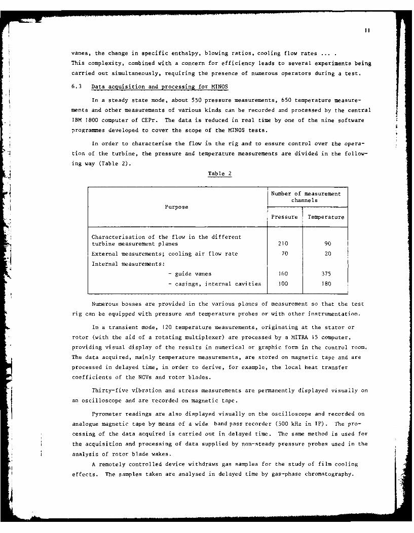
6.3 Data acquisition and processing for MINOS
In a steady state mode, about 550 pressure measurements, 650 temperature measure-
ments and other measurements of various kinds can be recorded and processed by the central
IBM 1800 computer of CEPr. The data is reduced in real time by one of the nine software
programmes developed to cover the scope of the MINOS tests.
In order to characterise the flow in the rig and to ensure control over the opera-
tion of the turbine, the pressure and temperature measurements are divided in the follow-
ing way (Table 2).
Table 2
Number of measurementchannels
Purpose
Pressure Temperature
Characterisation of the flow in the different
turbine measurement planes 210 90
External measurements; cooling air flow rate 70 20
Internal measurements:
- guide vanes 160 375
- casings, internal cavities 100 180
Numerous bosses are provided in the various planes of measurement so that the test
rig can be equipped with pressure and temperature probes or with other instrumentation.
In a transient mode, 120 temperature measurements, originating at the stator or
rotor (with the aid of a rotating multiplexer) are processed by a MITRA 15 computer,
providing visual display of the results in numerical or graphic form in the control room.
The data acquired, mainly temperature measurements, are stored on magnetic tape and are
processed in delayed time, in order to derive, for example, the local heat transfer
coefficients of the NGVs and rotor blades.
Thirty-five vibration and stress measurements are permanently displayed visually on
an oscilloscope and are recorded on magnetic tape.
Pyrometer readings are also displayed visually on the oscilloscope and recorded on
analogue magnetic tape by means of a wide band pass recorder (500 kHz in IF) . The pro-
cessing of the data acquired is carried out in delayed time. The same method is used for
the acquisition and processing of data supplied by non-steady pressure probes used in the
* analysis of rotor blade wakes.- I A remotely controlled device withdraws gas samples for the study of film cooling
effects. The samples taken are analysed in delayed time by gas-phase chromatography.
12
7 EXAMPLES OF RESULTS
The different tests carried out on the MINOS facility have produced numerous results
which, on the one hand enabled the limits of validity of prediction methods to be
established, and, on the other hand made it possible, in a typical engine environment,
to characterise experimentally various phenomena which, up to then, had only been studied
using static model test rigs.
In order to illustrate the capabilities of the MINOS test facility, four examples
of the results obtained are presented below.
7.1 Pressure fluctuations - turbulence
The use of pressure probes with short response times has made it possible to
characterise the aerodynamic turbulence of the flow at inlet to the HP nozzle guide vanes.
A mean level of turbulence of the order of 9% has been recorded at the experimental
operation point. The radial and circumferential heterogeneity of this parameter, observed
at the test vanes, must be attributed to the geometry of the combustion chamber.
A comparison of the spectra of pressure fluctuations of the flow at different vane
heights is shown in Fig 7. The fluctuations detected close to the outer casing are
larger relative to those measured at mid-span. Certain dominant frequencies appear in
the spectra; their origin is still ill-defined.
The examination of such experimental data is relevant to studies of turbulent
flow in turbo machinery being carried out at numerous laboratories and to its
influence upon various phenomena such as boundary layers and the film cooling efficiency
of blades.
7.2 Nozzle guide vane heat transfer coefficients
The experimental distribution of heat transfer coefficient on the pressure and
suction surfaces of the nozzle guide vanes with no film cooling is illustrated in Fig 8.
It is compiled from numerous successive cycles (stopping and starting of internal cooling
to the vanes) to minimise the errors associated with the scatter of temperature measure-
ments.
The difficulty of fitting thermocouples sufficiently close to each other near the
vane leading edge makes it impossible to accurately characterise the distribution of
heat transfer coefficients in this zone. Optical pyrometry or other new methods of
measurement should offer a solution to this problem. This study demonstrates the possi-
bility of maintaining, on aerodynamically well-designed blades, a laminar flow over a
high proportion of the profile, a condition favourable for cooling. In the case of the
suction surface, quite good agreement is observed between the experimental distribution
of heat transfer coefficient and that calculated by the method described in Ref 15. In
the case of the pressure surface, calculation indicates a re-laminarisation of the bound-
ary layer which the tests do not reveal.
Moreover, it seems that, in the particular case of MINOS, the engine environment
does not appreciably modify the heat transfer coefficients relative to those found using
static model tests.
13
7.3 Optical pyrometry on rotor blades
Fig 9 illustrates surface temperature profiles measured by optical pyrometry on the
suction surface of a rotor blade for two cooling air flow rates.
This technique can be used to determine temperature gradients on the blade surfaces,
especially in the vicinity of leading edges and around cooling holes, and to identify
poorly cooled zones. In the example shown, the effect of cooling flow rate on the
temperature at the edge of a cooling hole can be seen. The temperature contour plots thus
established may then be used as a data base for validation of methods of predicting the
efficiency of internal convection and film cooling systems.
7.4 Cooling the platforms of the HP nozzle guide vines
The cooling of the platforms of the HP nozzle has been studied both for the case of
film cooling from two rows of holes upstream of the platforms and, for the case of emis-
sion through perforations distributed over these same platforms.
In the first case, the efficiency of the protective film is derived from analyses
of gas samples taken from numerous points on the platform surfaces. Fig 10 shows a
section taken near the outer wall.
In the second case, the thermal iso-efficiencies have been derived from temperature
measurements at the wall, carried out using thermocouples. The results obtained are
presented in Fig 11.
8 CONCLUSIONS
The studies carried out using the MINOS test rig have demonstrated the flexibility
of application of this type of testing. The ability to independently vary a large number
of parameters has eased the analytical task.
The influence of an engine environment on heat transfer coefficients or on the
efficiency of film cooling has been studied.
Correct operation of various instruments which had previously only been used for
laboratory studies has been demonstrated on this rig. Detailed measurements carried out
using this facility have made it possible to state that the prediction methods in use for
determination of aerodynamic performance and thermal behaviour of gas turbines are valid.
The study programme currently being pursued should provide more detailed knowledge
for the optimisation of blade cooling systems and should provide confirmation of the
validity of methods used to predict their life.
In conclusion, the MINOS test rig appears to be an effective tool both for the gas
turbine designer and for the research worker who, on the basis of results acquired
using this facility, can specify supplementary tests on static test rigs with more con-
fidence and refine prediction methods, making it possible by this means, to accelerate the
development of gas turbines.
H °
14
DISCUSSION
A.J.B. Jackson, UK:
To what temperature do you intend to develop and test the MINOS apparatus in the
future, and what are the limitations to increasing the test temperatures?
Author's reply:
The MINOS test rig has been designed for a turbine inlet temperature of 15000C
r and we do not, at present, envisage any increase in this temperature, since this would
require considerable modifications.
15
Table I
THE PLACE OF MI1NOS AS A TEST VEHICLE IN A PROGRAMME OF HIGH TEMPERATURE TURBINE RESEARCH
Advantages Disadvantages
Full-scale engine Engine test conditions Complexity and lack of flexibilitytesting of tests
Interactions between parameters
Difficulties in obtaining detailedmeasurements
Difficulty in correlating resultswith other types of engine
.4 High cost
Scale model test Studies of the effects on over- Test conditions do not alwaysrigs all performance of separate accurately reproduce engine
elements conditions
Relative simplicity of test Results often too universal toinstallations permit detailed analysis of
Easy and rapid parametric study eeetr hnmn
Variable test conditions
* Relatively moderate cost
-1 Conclusions directly applicableto engine development
Studies using Detailed analysis of fundamen- Test conditions sometimes farsimple apparatus tal phenomena removed from those encountered in
Refined and precise engines
measurements carried out
Close theory-experimentrc lationship
Fundamental research: short,medium and long-term objectives
Synthesis of Development of prediction Difficulties in correlating pre-fundamental methods for turbomachinery diction hypotheses with complexresearch design phenomena
Difficulties in validating calcula-tion methods under engine testconditions
MINOS experi- Validation of performance and Technical constraints in themental rig design prediction methods for design of the test rig imposed by
high-temperature turbines in the measurements to be carriedthe presence of an engine outenvironment Difficulties in equipping the test
Intermediate rig between model rig with instrumentationtest rigs and engine testing
C0 (detailed measurements possible,flexibility of control ofoperating parameters)
Close relationships with testengines, tests on model rigsand fundamental research
16
REFERENCES
No. Author Title, etc
I P. Alesi Des hautes temperatures devant turbine sur turborgacteur et
turbines A gaz. (High turbine inlet temperatures in turbo-jet
engines and gas turbines.)
AGARD CP 73-71, September 1970
2 Y. le Bot Techniques de mesures dans les turbines a haute temperatures.M. Charpenel (Measurement techniques for high temperature turbines.)J. MichardY. Hours AGARD Conference: High temperature problems in gas turbineR. Larguier engines. AGARD-CP-229, Ankara, September 1977J. Wilhelm
3 C. Freeman The relationship between steady and unsteady special distortion.
In unsteady phenomena in turbomachines.
AGARD CPP No.177 (1975)
4 R.P. Benedict Fundamentals of temperature, pressure and flow measuremens.John Wiley and Sons, Inc. (1969)
5 R.R. Dils Dynamic gas temperature measurements in a gas turbine transition
duct exit.
ASME Gas Turbine Conference, Washington, April 1973,
Paper No.73GT7
6 R. Larguier Mesures instationnaires dans les turbomachines.
A. de Sievers (Non-steady measurements in turbomachinery.)
La Recherche Agrospatiale, No.1975-5, Sept-Oct
7 A. Boutier Laser anemometry applied to research compressor.C. FertinR. Lrgier Communication to the ISL-AGARD working party on laser anemometry.R. Larguier
J. Lefevre Franco-German Institute of Saint-Louis, 5-7 May, 1976.A. de Sievers ONERA T.P., No.1976-43
8 R. Larguier M~thodes de mesures instationnaires dans les turbomachines.
A. de Sievers (Methods of non-steady measurements in turbomachinery.)
Agronautique et Astronautique, No.46, 3 (1974)
9 Y. le Bot Caract~risation exp6rimentale des 6coulements internes dans
R. Larguier les turbomachines. (Experimental characterisation of internal
flows in turbomachinery.)
Revue francaise de m~canique, No.57 (1976)
10 J. Michard Mesures de flux de chaleur sur aubes fixes de turbines.
(Heat flux measurements on turbine nozzle guide vanes.)
In High temperature turbines, AGARD CP 73-71, September 1970
II M. Charpenel Pyrom~tre infra-rouge destin4 la mesure des tempiratures
J. Wilhelm d'ailettes de turbine. (Infra-red pyrometer designed for the
temperature measurement of turbine blades.)
Mesures, r~guZation, automatisme, 41, No.4, 41-50, April 1976
17
REEWF CES (concluded)
No. Author Title, etc
12 S. Denoyer Mesure des densitds de flux thermique. (Measurement of heat
flux densities.)
Entropie, No.54, November-December 1973
13 J.J. Nicolas Protection thermique des tuy~res supersoniques par film gazeux.
M. Izard (Thermal protection of supersonic jet pipes by gas films.)
La Recherche A(rospatiale, No.1971-4, July-August, 197-208 (1971)
14 C. Verdier Application de la m~trologie des gaz de combustion au domaine
des turbor4acteurs. (Application of metrology to combustion
gases in the field of turbo-jet engines.)
Revue Gn(rale de Thermique, No. 166, October 1975
15 D. Arnal Etude exprimentale et thgorique de la transition de la couche
J.C. Juillen limite. (Experimental and theoretical study of boundary layer
transition.)
Recherche A~rospatiale No.1977-2, March-April (1977)
r!
F4
I-
I-
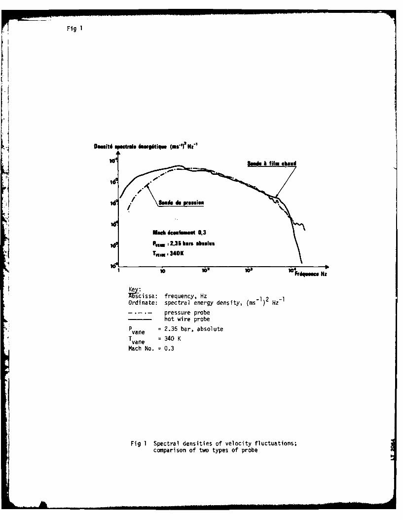
Fig 1
0m6 sp'te hoqs 6WiU" (MvI? NZ"
~Send@ 6 film AM~
10 .
iach 6cesuhmet 0.3
id' Ps.. : 2,35 bars ahelus
Tri.: 340K
10 10 i@* frdqeace NZKe:
'scissa: frequency, Hz 1 2Ordinate: spectral energy density, (ms- ) Hz
pressure probehot wire probe
Pvane = 2.35 bar, absolute
Tvane = 340 K
Mach No. = 0.3
Fig 1 Spectral densities of velocity fluctuations;comparison of two types of probe
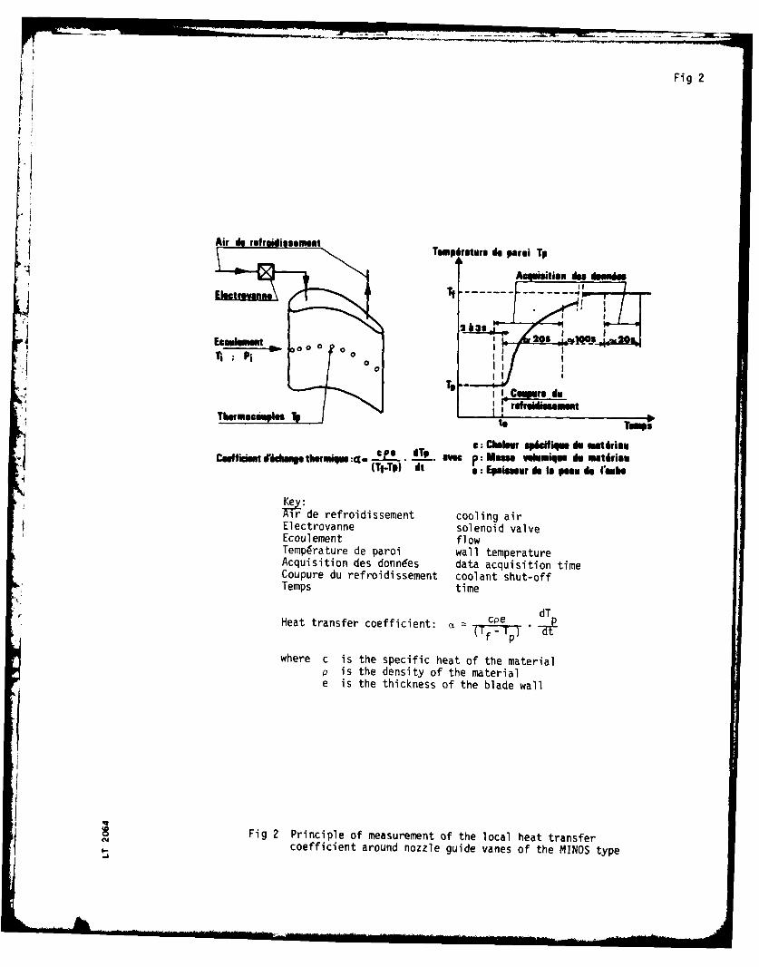
Fig 2
Air is rutr idissseutTemp fatefs io parsi TP
*2 S
Wr Chusu spstiu ism0r
refroidissement coligui
Ecouoca l eme flow .
Cafiis ideAcqigston d es ILL nn P esp data acqui itio time fi
Coupr d refroidissement coolant shu-of
Temps time
Heat transfer coefficient: - coe dT
where c is the specific heat of the materialp is the density of the materiale is the thickness of the blade wall
Fig 2 Principle of measurement of the local heat transfercoefficient around nozzle guide vanes of the MINOS type
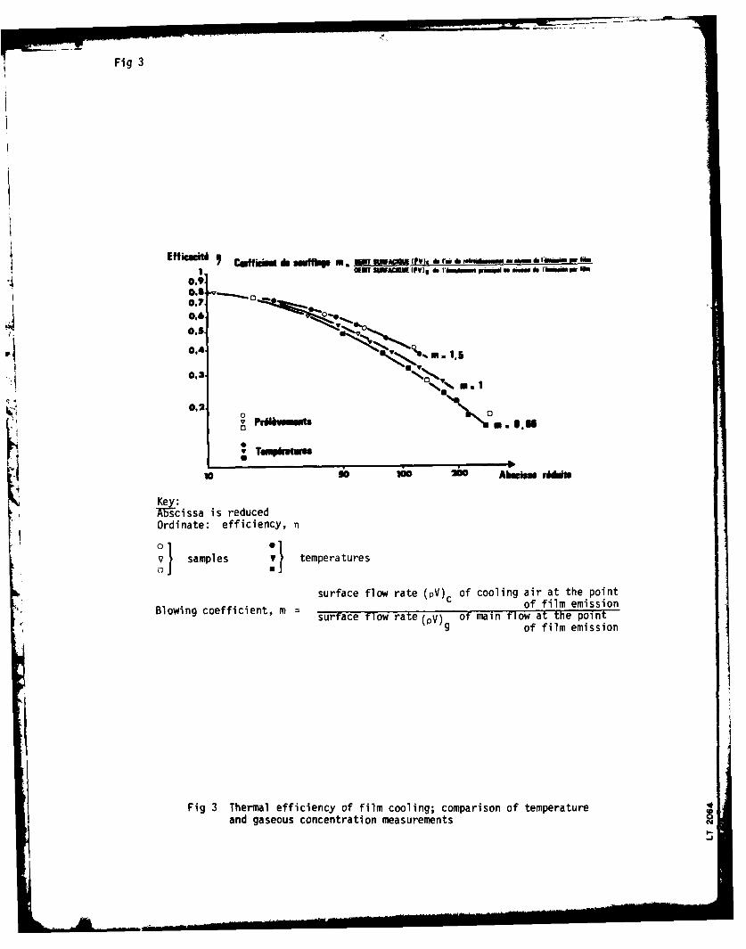
Fig 3
Effiautim. mnf -.-.. m-(e'd rd ,-." ': :-. do-.'-m"I, ll I@ENT AACOIII V) I do 'llll I" WI M ft"lM 6b I6Min Pra
0,9.
0,70,7 m -,"
0.6.
0.5
0,3
0.20
v Tumpiutes,
10 ob A bins0stim
Key:A scissa is reducedOrdinate: efficiency, n
v samples VI temperatures
surface flow rate (pV)c of cooling air at the point
Blowing coefficient, m of film emissionsurface flow rate (pV) of main flow at the point
g of film emission
Fig 3 Thermal efficiency of film cooling; comparison of temperatureand gaseous concentration measurementsL I.
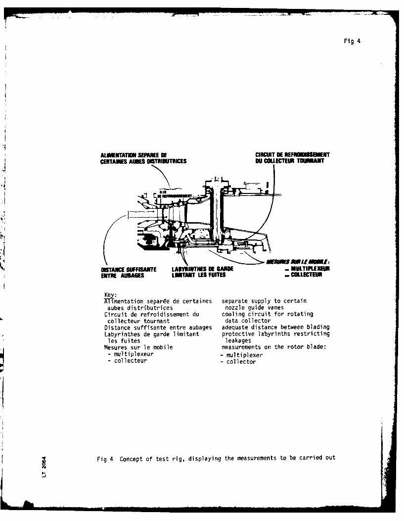
Fig 4
-~AIJMETATM SEFAREE OF CIRCUIT DE REFMNIDISSIENTCERTAINES AIDES DISTRIhUTRICES NJl COLLECTEUR TODANT
hfXM W ifLIAE:DIISTANC SU*FISAUTE LABYRNITNES WI SARDE - MULTIPLEXUIRENTRE AUSABES LITANT LES FUITES - COLLECTIUD
Key1mentation separde de certaines separate supply to certainaubes distributrices nozzle guide vanes
Circuit de refroidissement du cooling circuit for rotatingcollecteur tournant data collector
Distance suffisante entre aubages adequate distance between bladingLabyrinthes de garde limitant protective labyrinths restrictingles fuites leakages
Mesures sur le mobile measurements on the rotor blade:U- multiplexeur - multiplexer
- collecteur - collector
Fig 4 Concept of test rig, displaying the measurements to be carried out
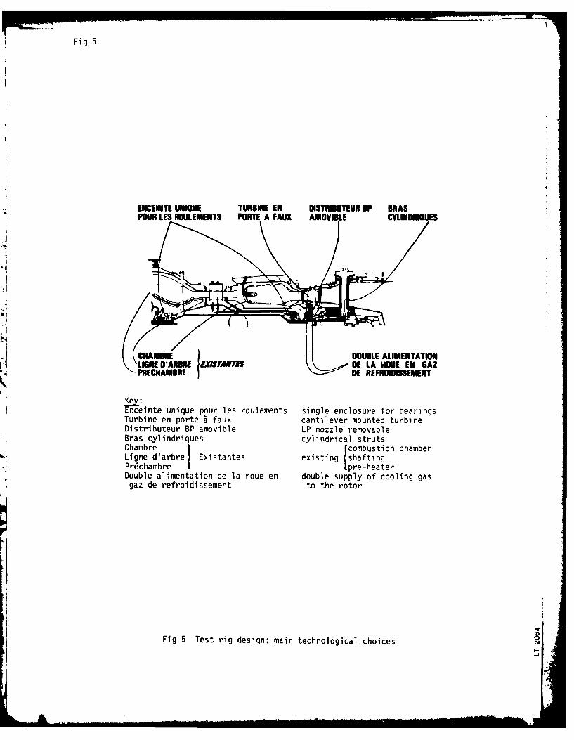
Fig 5
ENCEINTE UNI3UE TURBINE EN DISTRIBUTEUR BP BRASPOUR LES ROULEMENTS PORTE A FAUX AMOVIBLE CYLORGUES
CHA DOUBLE ALIMENTATIONLE WARRE EXIlMST GE LA WhE EN GAZ'PRlECHAMBRE DE REFROIDiSSEMENT
Kceinte unique pour les roulements single enclosure for bearingsTurbine en porte a faux cantilever mounted turbineDistributeur BP amovible LP nozzle removableBras cylindriques cylindrical strutsChambre 1 Jcombustion chamberLigne d'arbrel Existantes existing shaftingPr~chambre 1pre-heaterDouble alimentation de la roue en double supply of cooling gasgaz de refroidissement to the rotor
Fig 5 Test rig design; main technological choices
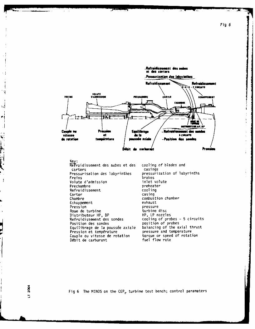
Fig 6
-Rutroidissomet do$n Bob"at des carters
-premsristion des labyinthes
Ret rsldisseomart Rafrnidk~sament
VOUT
Couple eo Prussis. Eqwilihrme -Refroidlmm des sodesvitesse atd I CHUMU~
do rotation tempraturs Poes"~ aXial -position do$ sondes
Key:eT'roidissement des aubes et des cooling of blades andhcarters casings
Pressurisation des labyrinthes pressurisation of labyrinthsFre ins brakesVolute d'admission inlet volutePrechambre preheaterRefroidissement coolingCarter casingChambre combustion chamberEchappement exhaustPression pressureRoue de turbine turbine discDistributeur HP, BP HP, LP nozzlesRefroidissement des sondes cooling of probes - 5 circuitsPosition des sondes position of probesEquilibrage de la pouss~e axiale balancing of the axial thrustPression et temperature pressure and temperatureCouple ou vitesse de rotation torque or speed of rotation
Ddbit de carburant fuel flow rate
Fig 6 The MINOS on the CEPr turbine test bench; control parameters
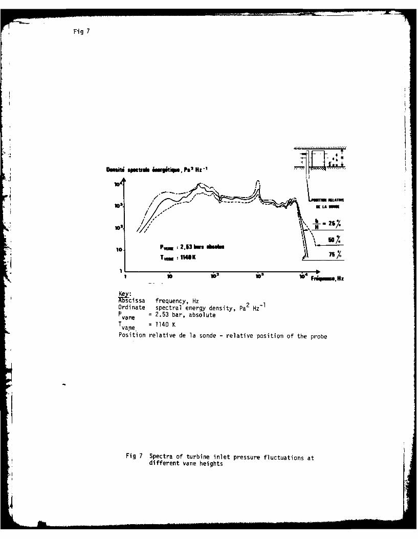
Fig 7
- *-*..I LATMAd U LA
10. P .:2Ihrs ~IIK 7s7/,
A5~scissa frequency, Hz 2 -Ordinate spectral energy density, Pa2 Hz1P vae = 2.53 bar, absolute
T vae =1140 KPosition relative de la sonde - relative position of the probe
Fig 7 Spectra of turbine inlet pressure fluctuations atdifferent vane heights
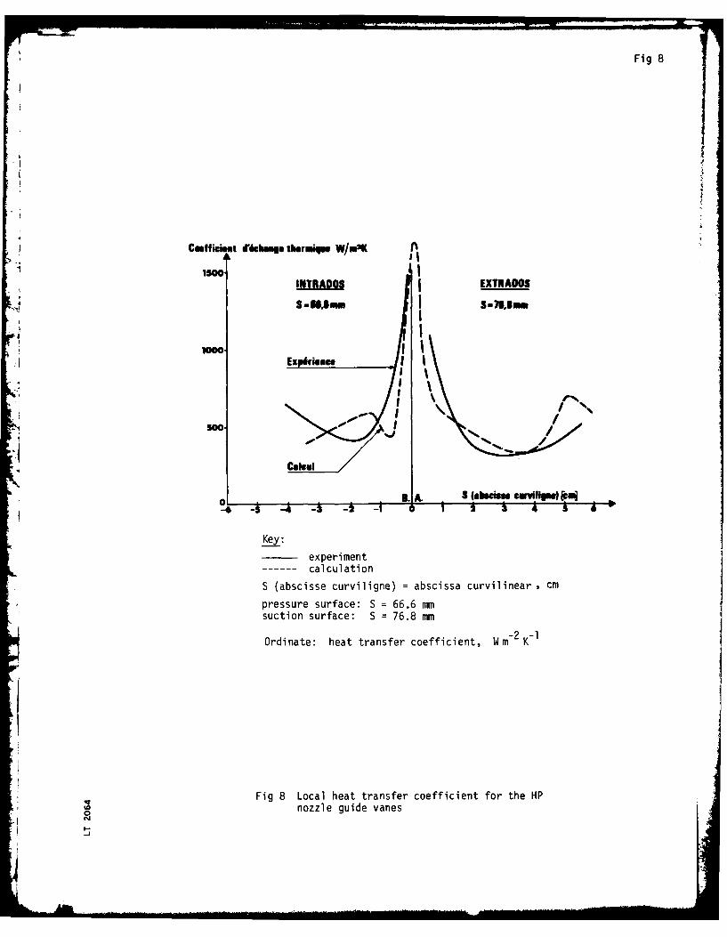
Fig 8
4 9Caeffimt di lsag thermiqw W/M2K A
AISMINTRADOS EXTRADOS
S - U ~ au mS - 711. 1m m
Ex
peri
me
C~kI'
S Iswis ewl )[oi5 /4 -S 3 -1 0 i i
calculation
S (abscisse curviligne) = abscissa curvilinear , cm
pressure surface: S = 66.6 mmsuction surface: S = 76.8 mm
Ordinate: heat transfer coefficient, Wm-2 K-1
Fig 8 Local heat transfer coefficient for the HPnozzle guide vanes
-_
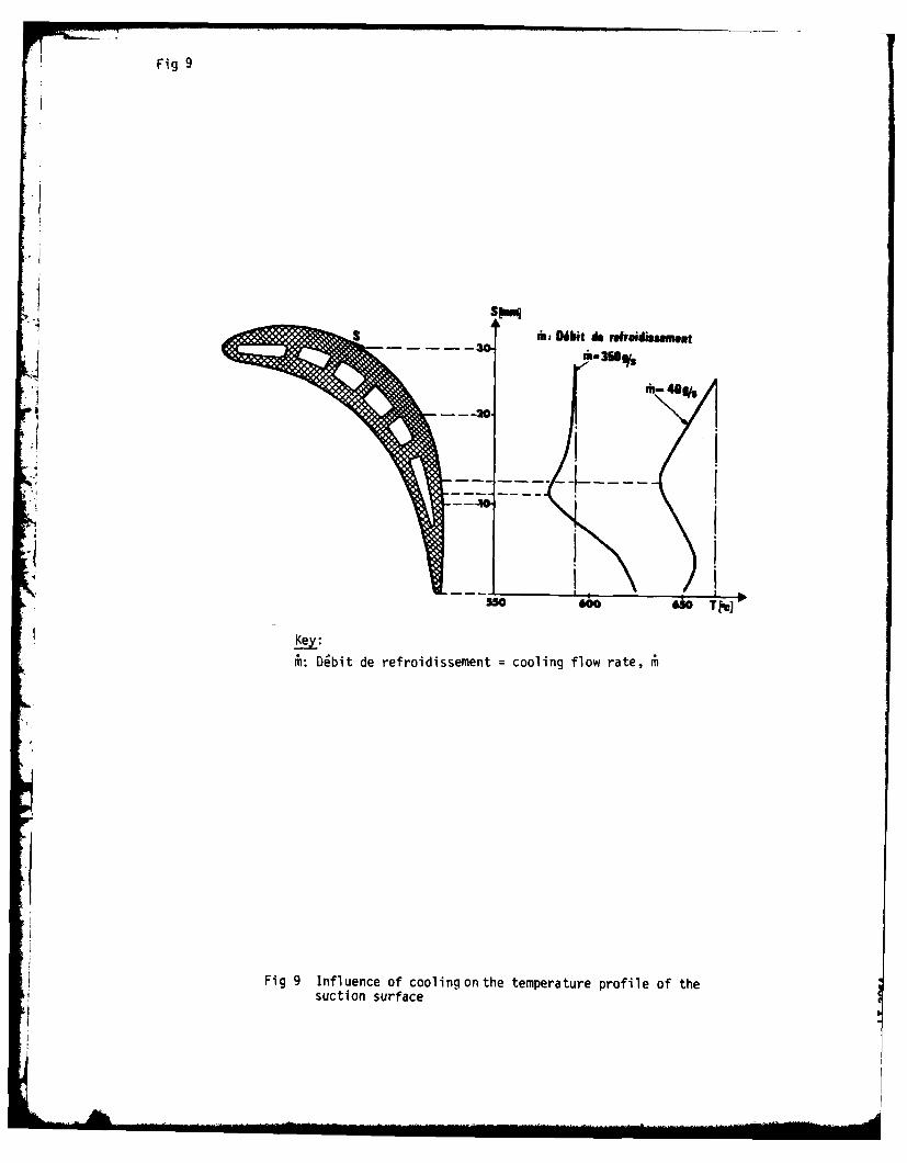
Fig 9
Sim: DWbit do refroidissment
m-360%
Key:
i: Dgbit de refroidissement = cooling flow rate,
Fig 9 Influence of cooling onthe temperature profile of the
suction surface
*1
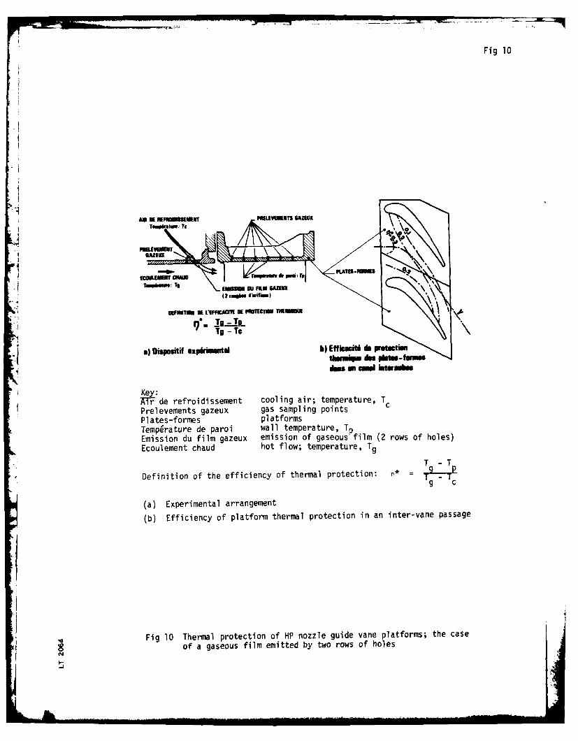
Fig 10
AM N EFIISIu POLEKTI GAZEUXTO.Pirtaw: TS
'i1
a hPNM eIif eprnnS h fust
,MNf "dNp* p PATES -IPml
:TI ._ ,ISSI OU FILM GZO
OEFROM 1We~ VEFCC OEPM: TiA
TS -Tpe
8) Dispe"if ixphin al4 b) Efficscit d & pretetinwm du es d-Ism
dim M a imnWOOlI
Air de refroidissement cooling air; temperature, TPrelevements gazeux gas sampling pointsPlates-formes platformsTemperature de paroi wall temperature, TpEmission du film gazeux emission of gaseous film (2 rows of holes)Ecoulement chaud hot flow; temperature, Tg
T -T
Definition of the efficiency of thermal protection: n* = I
g c
(a) Experimental arrangement
(b) Efficiency of platform thermal protection in an inter-vane passage
Fig 10 Thermal protection of HP nozzle guide vane platforms; the case
of a gaseous film emitted by two rows of holes
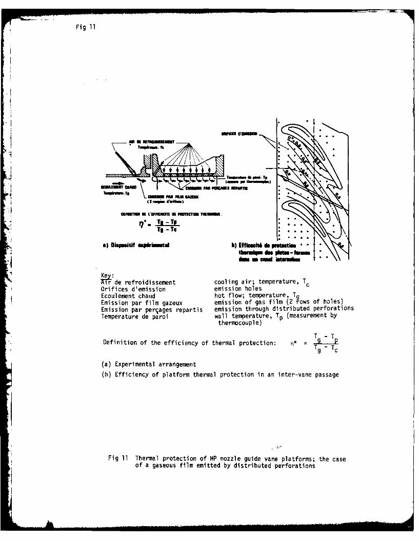
Fig 11
T , Tp
miim U LWPC1I U~UIT ammr:
T -T .. .
) Dmepnitif cpkhmtaI h) Effio M 6 pth inT
Key:W-TF de refroidissement cooling air; temperature, TcOrifices d'emission emission holescEcoulement chaud hot flow; temperature, TgEmission par film gazeux emission of gas film (2 rows of holes)Emission par perjages repartis emission through distributed perforationsTemperature de paroi wall temperature, Tp (measurement by
thermocouple)
Definition of the efficiency of thermal protection: n* = T - TpT - Tc
(a) Experimental arrangement
(b) Efficiency of platform thermal protection in an inter-vane passage
Fig 11 Thermal protection of HP nozzle guide vane platforms; the case
of a gaseous film emitted by distributed perforations
iA
Library Translation 2064
ADVANCE DISTRIBUTION:
RMCSITCDRIC 70BAe, HatfieldNGTE 13Rolls-Royce Ltd
RAE
DDMain Library
aJ
*1!