Embed Size (px)
Citation preview
11451 Belcher Road South, Largo, FL 33773 • USA • Tel +1 (727) 447-6140 • Fax +1 (727) 442-5699www.onicon.com • [email protected] 08-15
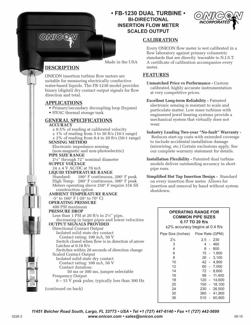
• FB-1230 DUAL TURBINE •BI-DIRECTIONAL
INSERTION FLOW METERSCALED OUTPUT
DESCRIPTION
ONICON insertion turbine flow meters are suitable for measuring electrically conductive water-based liquids. The FB-1230 model provides binary (digital) dry contact output signals for flow direction and total.
APPLICATIONS • Primary/secondary decoupling loop (bypass) • HVAC thermal storage tank
GENERAL SPECIFICATIONS ACCURACY ± 0.5% of reading at calibrated velocity ± 1% of reading from 3 to 30 ft/s (10:1 range) ± 2% of reading from 0.4 to 20 ft/s (50:1 range) SENSING METHOD Electronic impedance sensing (non-magnetic and non-photoelectric) PIPE SIZE RANGE 2½” through 72” nominal diameter SUPPLY VOLTAGE 24 ± 4 V AC/DC at 70 mA LIQUID TEMPERATURE RANGE Standard: 180° F continuous, 200° F peak High Temp: 280° F continuous, 300° F peak Meters operating above 250° F require 316 SS construction option AMBIENT TEMPERATURE RANGE -5° to 160° F (-20° to 70° C) OPERATING PRESSURE 400 PSI maximum PRESSURE DROP Less than 1 PSI at 20 ft/s in 2½” pipe, decreasing in larger pipes and lower velocities OUTPUT SIGNALS PROVIDED Directional Contact Output Isolated solid state dry contact Contact rating: 100 mA, 50 V Switch closed when flow is in direction of arrow Latches at 0.18 ft/s Switches within 20 seconds of direction change Scaled Contact Output Isolated solid state dry contact Contact rating: 100 mA, 50 V Contact duration: 50 ms or 300 ms, jumper selectable Frequency Output 0 – 15 V peak pulse, typically less than 300 Hz
(continued on back)
CALIBRATION
Every ONICON flow meter is wet calibrated in a flow laboratory against primary volumetric standards that are directly traceable to N.I.S.T. A certificate of calibration accompanies every meter.
FEATURES
Unmatched Price vs Performance - Custom calibrated, highly accurate instrumentation at very competitive prices.
Excellent Long-term Reliability - Patented electronic sensing is resistant to scale and particulate matter. Low mass turbines with engineered jewel bearing systems provide a mechanical system that virtually does not wear.
Industry Leading Two-year “No-fault” Warranty - Reduces start-up costs with extended coverage to include accidental installation damage (miswiring, etc.) Certain exclusions apply. See our complete warranty statement for details.
Installation Flexibility - Patented dual turbine models deliver outstanding accuracy in short pipe runs.
Simplified Hot Tap Insertion Design - Standard on every insertion flow meter. Allows for insertion and removal by hand without system shutdown.
Made in the USA
OPERATING RANGE FOR COMMON PIPE SIZES
0.17 TO 20 ft/s±2% accuracy begins at 0.4 ft/s
Pipe Size (Inches) Flow Rate (GPM)2½ 2.5 - 230
3 4 - 4604 8 - 8006 15 - 1,8008 26 - 3,100
10 42 - 4,90012 60 - 7,05014 72 - 8,60016 98 - 11,40018 120 - 14,60020 150 - 18,10024 230 - 26,50030 360 - 41,90036 510 - 60,900
11451 Belcher Road South, Largo, FL 33773 • USA • Tel +1 (727) 447-6140 • Fax +1 (727) 442-5699www.onicon.com • [email protected] 08-15
Typically 30" - 36"
depending on pipe size andheight of valve
assembly.
CLEARANCE REQUIRED
FOR INSTALLATION
½" FNPT conduit connection
Minimum Hole Size = 1"Must be centered
Insertion depthgage provided with each meter
FLOW
Connect factory wiresto field wires in appropriatejunction box.
Standard Installation Kit for Steel Pipe
1" Full port ball valve1" Close nipple 1" Branch outlet
Detail of hot tap adapterwith turbine assemblywithdrawn
1¼" for hot tap
To control system ONICON
Display orBTU Meter(Optional)
Typical Meter Installation(New construction or scheduled shutdown)
THIS AREA ACCEPTABLE
Horizontal Run Pipe
Acceptable to install in vertical pipe
Position meter anywhere in upper 240°for horizontal pipe
•
•
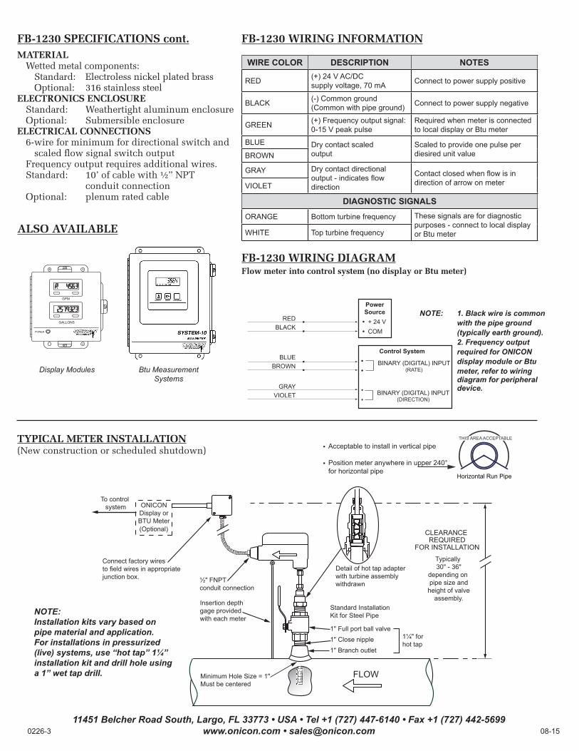
FB-1230 SPECIFICATIONS cont.MATERIAL Wetted metal components: Standard: Electroless nickel plated brass Optional: 316 stainless steelELECTRONICS ENCLOSURE Standard: Weathertight aluminum enclosure Optional: Submersible enclosureELECTRICAL CONNECTIONS 6-wire for minimum for directional switch and scaled flow signal switch output Frequency output requires additional wires. Standard: 10’ of cable with ½” NPT conduit connection Optional: plenum rated cable
ALSO AVAILABLE
NOTE: 1. Black wire is common with the pipe ground (typically earth ground). 2. Frequency output required for ONICON display module or Btu meter, refer to wiring diagram for peripheral device.
Power Source
• + 24 V• COM
Control System• •
• •
REDBLACK
BLUEBROWN
GRAYVIOLET
••
••
BINARY (DIGITAL) INPUT (DIRECTION)
BINARY (DIGITAL) INPUT (RATE)
FB-1230 WIRING INFORMATION
WIRE COLOR DESCRIPTION NOTES
RED (+) 24 V AC/DCsupply voltage, 70 mA Connect to power supply positive
BLACK (-) Common ground (Common with pipe ground) Connect to power supply negative
GREEN (+) Frequency output signal: 0-15 V peak pulse
Required when meter is connected to local display or Btu meter
BLUE Dry contact scaled output
Scaled to provide one pulse per diesired unit valueBROWN
GRAY Dry contact directional output - indicates flow direction
Contact closed when flow is in direction of arrow on meterVIOLET
DIAGNOSTIC SIGNALS
ORANGE Bottom turbine frequency These signals are for diagnostic purposes - connect to local display or Btu meterWHITE Top turbine frequency
FB-1230 WIRING DIAGRAMFlow meter into control system (no display or Btu meter)
SCROLL RESET PROGRAM10 3/4”
6”Btu MeasurementSystems
Display Modules
NOTE:Installation kits vary based on pipe material and application. For installations in pressurized (live) systems, use “hot tap” 1¼” installation kit and drill hole using a 1” wet tap drill.
TYPICAL METER INSTALLATION(New construction or scheduled shutdown)