Embed Size (px)
Citation preview
Fax: (0522)-2452581Telephone: (0522)-2465715Telegram: 'RAILMANAK', LucknowEmail : [email protected]
'l1ffif ~ - ~ ~
~ ~ 3th l'JT'1CIi ~~ - 226011
Government of India - Ministry of RailwaysResearch, Designs & Standards Organization,
LUCKNOW - 2260 II
Chief Electrical Engineers,
~ Central Railway, 2nd floor, Parcel Office Bldg., Mumbai CST-400 001~ East Central Railway, Hazipur - 844 101 (Bihar)~ Eastern Railway, Fairlie Place, Kolkata -700 001~ East Coast Railway, Railway Complex, Bhuvneshwar - 751 023~ North Central Railway, Allahabad - 211 001~ Northern Railway, Baroda House, New Oelhi-11 0 001.~ North Eastern Railway, Gorakhpur - 273001~ South Central Railway, Rail Nilyam, Secunderabad - 500 071.~ South East Central Railway, Bilaspur-495 004.~ South Eastern Railway, Garden Reach,Kolkata-700 043~ Southern Railway, Park Town, Chennai-600 003~ West Central Railway, Jabalpur 482 001.~ Western Railway, Churchgate, Mumbai -400 020
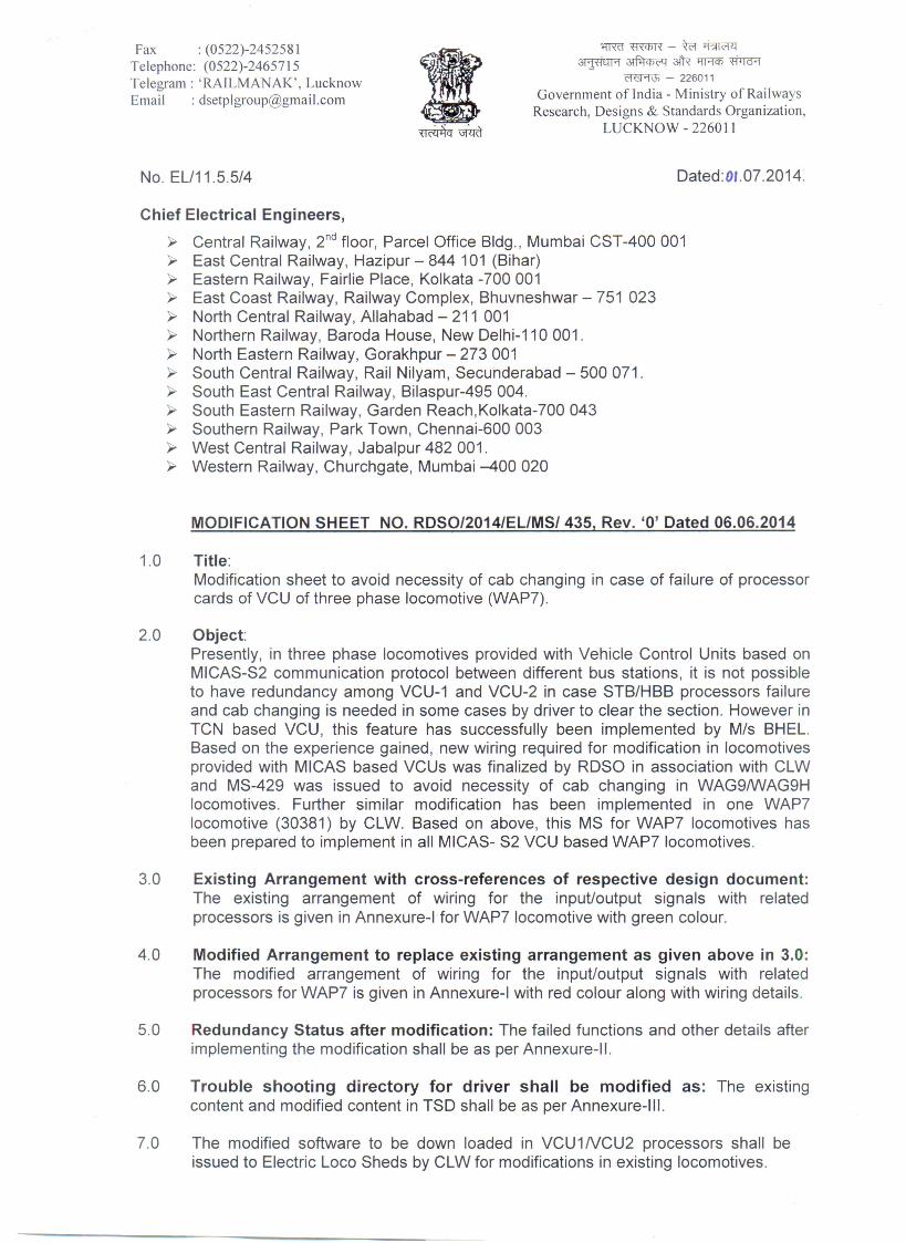
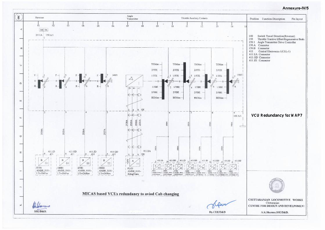
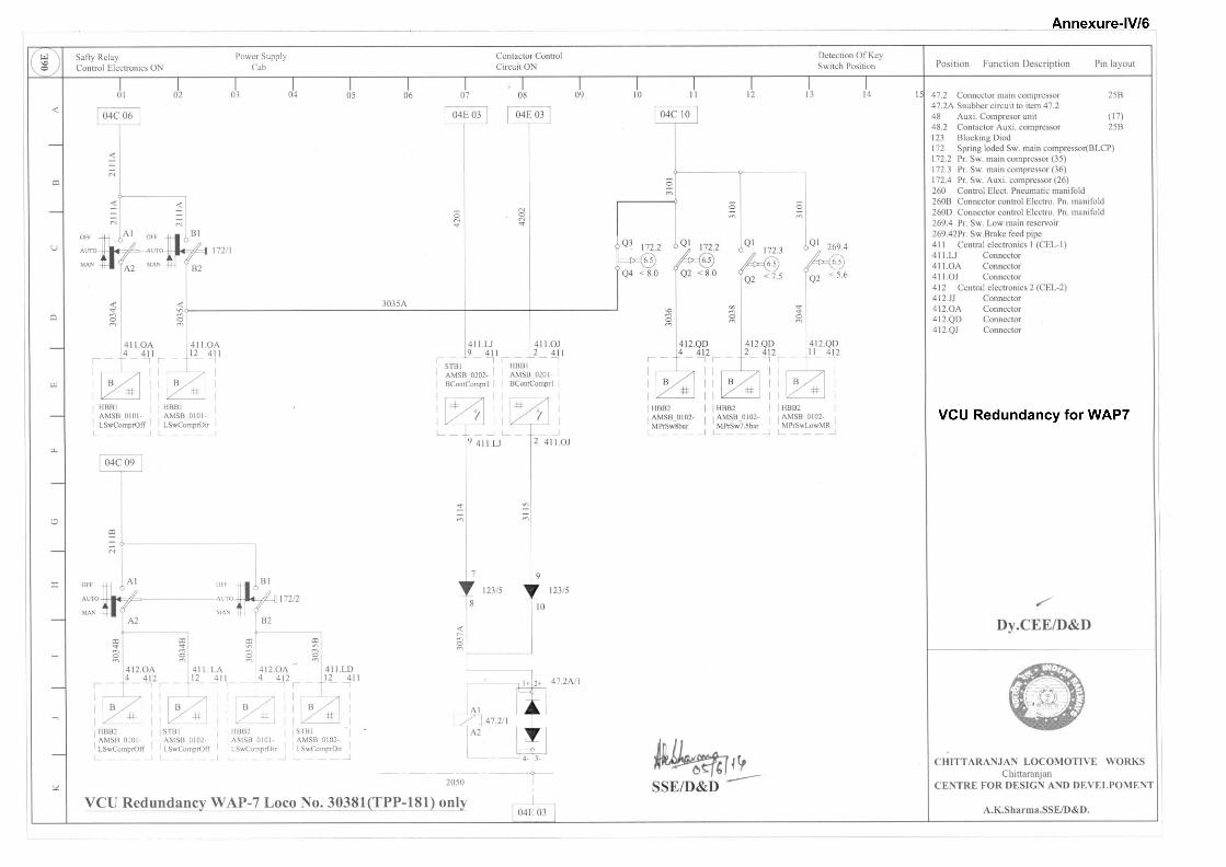
1.0 Title:Modification sheet to avoid necessity of cab changing in case of failure of processorcards of VCU of three phase locomotive (WAP7).
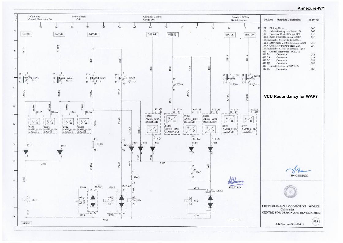
2.0 Object:Presently, in three phase locomotives provided with Vehicle Control Units based onMICAS-S2 communication protocol between different bus stations, it is not possibleto have redundancy among VCU-1 and VCU-2 in case STB/HBB processors failureand cab changing is needed in some cases by driver to clear the section. However inTCN based VCU, this feature has successfully been implemented by M/s BHEL.Based on the experience gained, new wiring required for modification in locomotivesprovided with MICAS based VCUs was finalized by ROSa in association with CLWand MS-429 was issued to avoid necessity of cab changing in WAG9IWAG9Hlocomotives. Further similar modification has been implemented in one WAP7locomotive (30381) by CLW. Based on above, this MS for WAP7 locomotives hasbeen prepared to implement in all MICAS- S2 VCU based WAP7 locomotives.
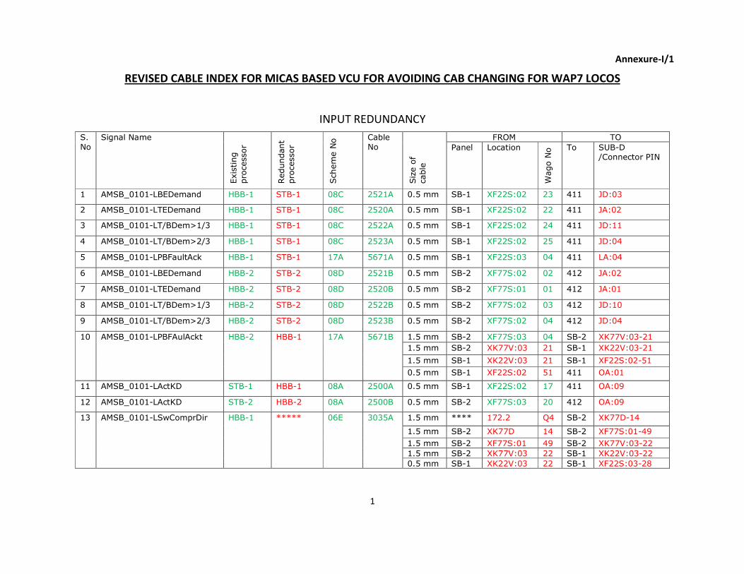
3.0 Existing Arrangement with cross-references of respective design document:The existing arrangement of wiring for the input/output signals with relatedprocessors is given in Annexure-I for WAP7 locomotive with green colour.
4.0 Modified Arrangement to replace existing arrangement as given above in 3.0:The modified arrangement of wiring for the input/output signals with relatedprocessors for WAP7 is given in Annexure-I with red colour along with wiring details.
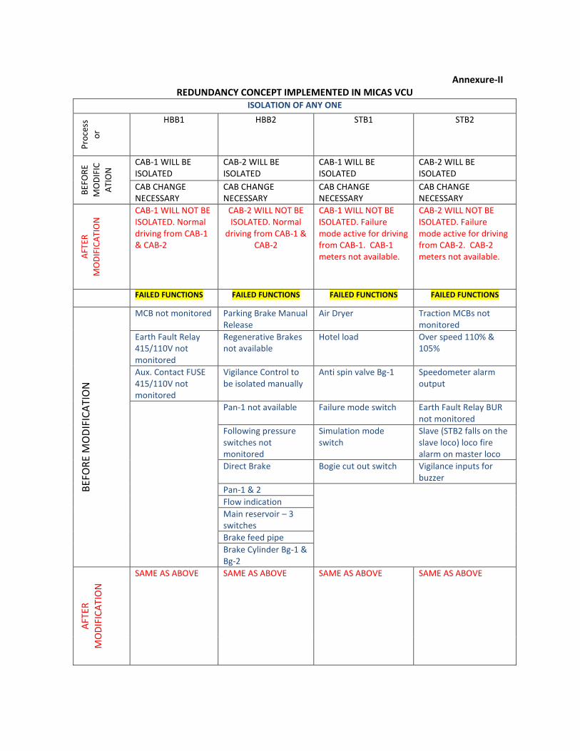
5.0 Redundancy Status after modification: The failed functions and other details afterimplementing the modification shall be as per Annexure-II.
6.0 Trouble shooting directory for driver shall be modified as: The existingcontent and modified content in TSO shall be as per Annexure-III.
7.0 The modified software to be down loaded in VCU1NCU2 processors shall beissued to Electric Loco Sheds by CLW for modifications in existing locomotives.
8.0 Application to class of locomotives:WAP-7 locomotives fitted with VCUs based on MICAS-S2 CommunicationProtocol.
9.0 Material Required:
(i) 0.5 sq.mm cable (as per CLW specification no. CLW/ES/3/0458 AIt.E) ofapproximately 60 m length and 1.5 sq.mm cable (as per CLW specification no.CLW/ES/3/0458 AIt.E) of approximately 50 m length per locomotive.
(ii) 6 Wago connector with 2 terminals per locomotive.
10.0 Material Rendered Surplus:
NIL.
11.0 Reference:
(i) Railway Board letter No. 2006/Elect(TRS)/441/8 dated 7-10-13.(ii) CLW letter No. C-D&DIT/42 dated 20-05-14.
12.0 Modification Drawing:
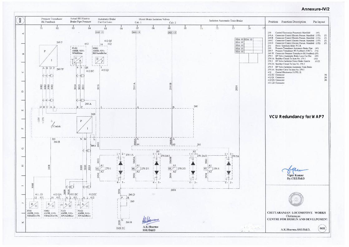
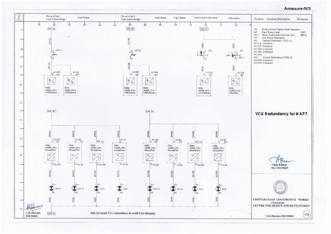
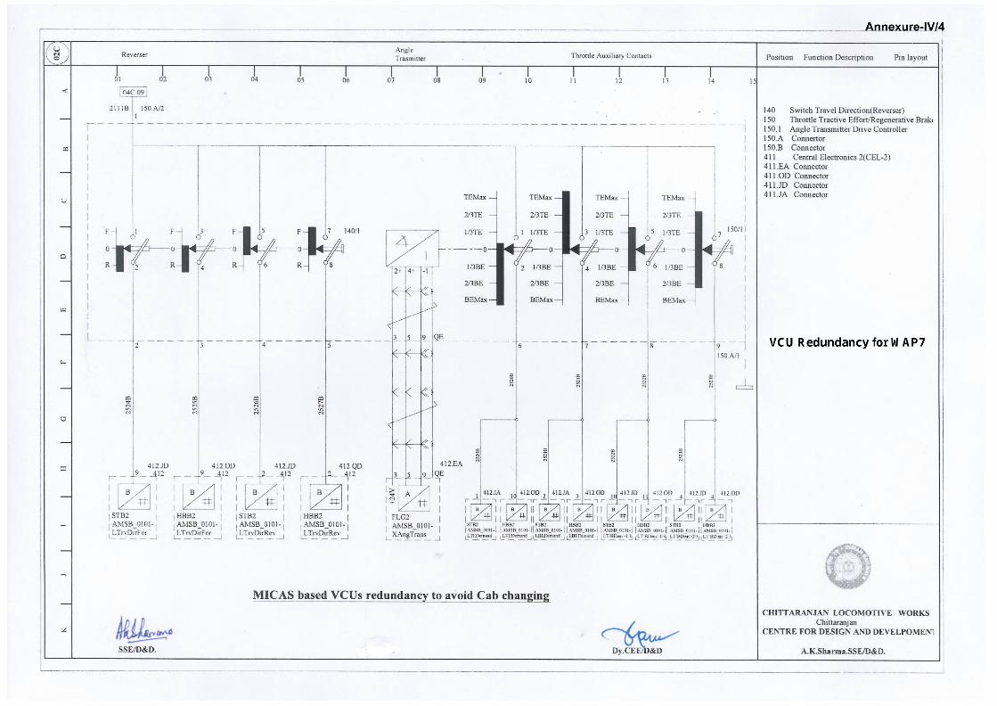
The modified schematics are enclosed at Annexure-IV.
13.0 Agency of Implementation:
CLW, POH workshops and Loco Sheds holding WAP7 type three phaselocomotives.
(AK~iifor Director General/Elect.
Copy to:-Secretary (Electric Traction),Railway Board,Rail Bhavan, New Delhi-11 0001.1. Chief Electrical Engineer, Chittaranjan Locomotive Works,
Chittaranjan-713331.2. Chief Works Manager, Electric Loco Workshop, Central Railway,
Bhusawal-425201.3. Chief Works Manager, Electric Loco Workshop, Eastern Railway,
Kancharapara, 24 Pargana (N) - 743145 (W.B.)4. Chief Works Manager, Loco, Carriage & Wagon Works, Western
Railway, Dahod, P.O. Freeland Gank - 389160 (Gujrat)5. Sr. DEE (TRS), Electric Loco Sheds,• Central Railway, Ajni (Nagpur)-440008.• Central Railway, Kalyan-421304 (Maharashtra)• East Central Railway, Gomoh-828 401• Eastern Railway, Howrah-711 106• Northern Railway, Ghaziabad (UP)-201 001.• South East Central Railway, BMY Complex, Bhilai,
Durg-490 025.• North Central Railway, Fazalganj, Kanpur - 208003• South Central Railway, Lallaguda, Secunderabad - 500 017.• South Eastern Railway, Tatanagar-831 002.• Southern Railway, Royapuram, Chennai-600 013.• West Central Railway, Tughlakabad, New Delhi-110 044.• Western Railway, Vadodara-390 002.
For kindinformationplease.For informationand necessaryaction please.
(A.K.Gp ami)for Director General/Elect
1
Annexure-I/1
REVISED CABLE INDEX FOR MICAS BASED VCU FOR AVOIDING CAB CHANGING FOR WAP7 LOCOS
INPUT REDUNDANCY
S.
No
Signal Name
Existing
processor
Redundant
processor
Scheme No Cable
No
Size of
cable
FROM TO
Panel Location
Wago No To SUB-D
/Connector PIN
1 AMSB_0101-LBEDemand HBB-1 STB-1 08C 2521A 0.5 mm SB-1 XF22S:02 23 411 JD:03
2 AMSB_0101-LTEDemand HBB-1 STB-1 08C 2520A 0.5 mm SB-1 XF22S:02 22 411 JA:02
3 AMSB_0101-LT/BDem>1/3 HBB-1 STB-1 08C 2522A 0.5 mm SB-1 XF22S:02 24 411 JD:11
4 AMSB_0101-LT/BDem>2/3 HBB-1 STB-1 08C 2523A 0.5 mm SB-1 XF22S:02 25 411 JD:04
5 AMSB_0101-LPBFaultAck HBB-1 STB-1 17A 5671A 0.5 mm SB-1 XF22S:03 04 411 LA:04
6 AMSB_0101-LBEDemand HBB-2 STB-2 08D 2521B 0.5 mm SB-2 XF77S:02 02 412 JA:02
7 AMSB_0101-LTEDemand HBB-2 STB-2 08D 2520B 0.5 mm SB-2 XF77S:01 01 412 JA:01
8 AMSB_0101-LT/BDem>1/3 HBB-2 STB-2 08D 2522B 0.5 mm SB-2 XF77S:02 03 412 JD:10
9 AMSB_0101-LT/BDem>2/3 HBB-2 STB-2 08D 2523B 0.5 mm SB-2 XF77S:02 04 412 JD:04
10 AMSB_0101-LPBFAulAckt HBB-2 HBB-1 17A 5671B 1.5 mm SB-2 XF77S:03 04 SB-2 XK77V:03-21
1.5 mm SB-2 XK77V:03 21 SB-1 XK22V:03-21
1.5 mm SB-1 XK22V:03 21 SB-1 XF22S:02-51
0.5 mm SB-1 XF22S:02 51 411 OA:01
11 AMSB_0101-LActKD STB-1 HBB-1 08A 2500A 0.5 mm SB-1 XF22S:02 17 411 OA:09
12 AMSB_0101-LActKD STB-2 HBB-2 08A 2500B 0.5 mm SB-2 XF77S:03 20 412 OA:09
13 AMSB_0101-LSwComprDir HBB-1 ***** 06E 3035A 1.5 mm **** 172.2 Q4 SB-2 XK77D-14
1.5 mm SB-2 XK77D 14 SB-2 XF77S:01-49
1.5 mm SB-2 XF77S:01 49 SB-2 XK77V:03-22
1.5 mm SB-2 XK77V:03 22 SB-1 XK22V:03-22
0.5 mm SB-1 XK22V:03 22 SB-1 XF22S:03-28
2
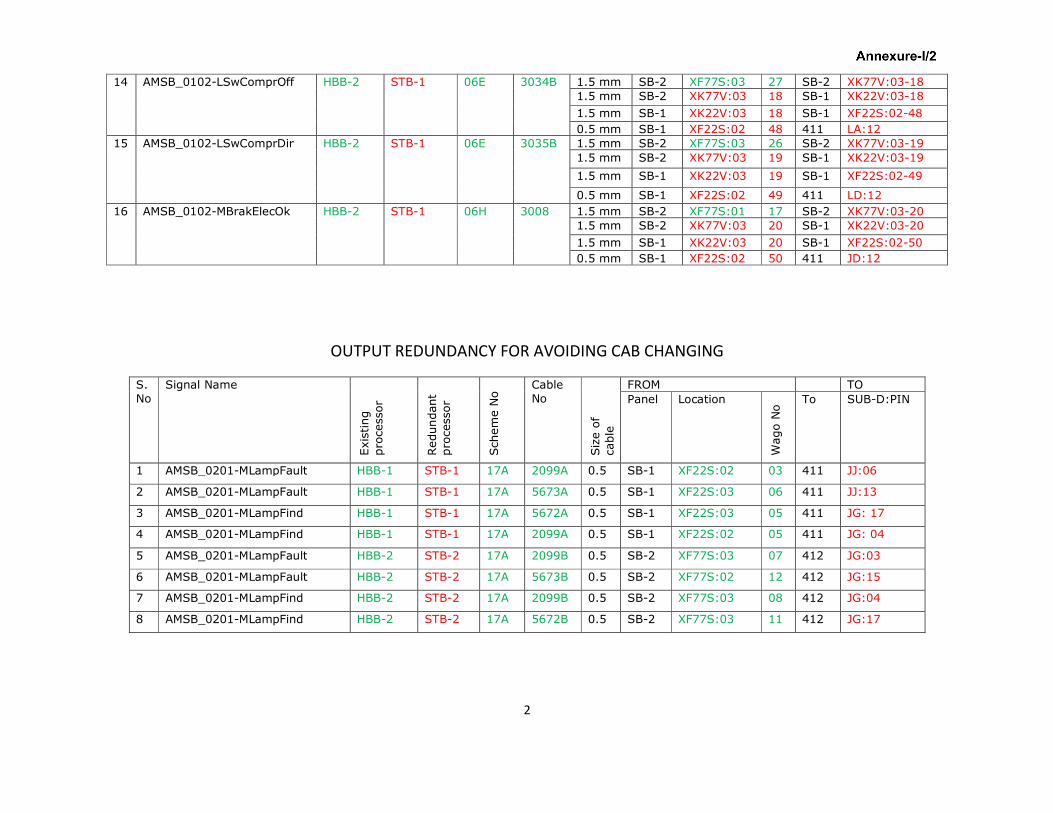
14 AMSB_0102-LSwComprOff HBB-2 STB-1 06E 3034B 1.5 mm SB-2 XF77S:03 27 SB-2 XK77V:03-18
1.5 mm SB-2 XK77V:03 18 SB-1 XK22V:03-18
1.5 mm SB-1 XK22V:03 18 SB-1 XF22S:02-48
0.5 mm SB-1 XF22S:02 48 411 LA:12
15 AMSB_0102-LSwComprDir HBB-2 STB-1 06E 3035B 1.5 mm SB-2 XF77S:03 26 SB-2 XK77V:03-19
1.5 mm SB-2 XK77V:03 19 SB-1 XK22V:03-19
1.5 mm SB-1 XK22V:03 19 SB-1 XF22S:02-49
0.5 mm SB-1 XF22S:02 49 411 LD:12
16 AMSB_0102-MBrakElecOk HBB-2 STB-1 06H 3008 1.5 mm SB-2 XF77S:01 17 SB-2 XK77V:03-20
1.5 mm SB-2 XK77V:03 20 SB-1 XK22V:03-20
1.5 mm SB-1 XK22V:03 20 SB-1 XF22S:02-50
0.5 mm SB-1 XF22S:02 50 411 JD:12
OUTPUT REDUNDANCY FOR AVOIDING CAB CHANGING
S.
No
Signal Name
Existing
processor
Redundant
processor
Scheme No Cable
No
Size of
cable
FROM TO
Panel Location
Wago No To SUB-D:PIN
1 AMSB_0201-MLampFault HBB-1 STB-1 17A 2099A 0.5 SB-1 XF22S:02 03 411 JJ:06
2 AMSB_0201-MLampFault HBB-1 STB-1 17A 5673A 0.5 SB-1 XF22S:03 06 411 JJ:13
3 AMSB_0201-MLampFind HBB-1 STB-1 17A 5672A 0.5 SB-1 XF22S:03 05 411 JG: 17
4 AMSB_0201-MLampFind HBB-1 STB-1 17A 2099A 0.5 SB-1 XF22S:02 05 411 JG: 04
5 AMSB_0201-MLampFault HBB-2 STB-2 17A 2099B 0.5 SB-2 XF77S:03 07 412 JG:03
6 AMSB_0201-MLampFault HBB-2 STB-2 17A 5673B 0.5 SB-2 XF77S:02 12 412 JG:15
7 AMSB_0201-MLampFind HBB-2 STB-2 17A 2099B 0.5 SB-2 XF77S:03 08 412 JG:04
8 AMSB_0201-MLampFind HBB-2 STB-2 17A 5672B 0.5 SB-2 XF77S:03 11 412 JG:17
Annexure-II
REDUNDANCY CONCEPT IMPLEMENTED IN MICAS VCU
ISOLATION OF ANY ONE
Pro
cess
or
HBB1 HBB2 STB1 STB2
BE
FO
RE
MO
DIF
IC
AT
ION
CAB-1 WILL BE
ISOLATED
CAB-2 WILL BE
ISOLATED
CAB-1 WILL BE
ISOLATED
CAB-2 WILL BE
ISOLATED
CAB CHANGE
NECESSARY
CAB CHANGE
NECESSARY
CAB CHANGE
NECESSARY
CAB CHANGE
NECESSARY
AF
TE
R
MO
DIF
ICA
TIO
N CAB-1 WILL NOT BE
ISOLATED. Normal
driving from CAB-1
& CAB-2
CAB-2 WILL NOT BE
ISOLATED. Normal
driving from CAB-1 &
CAB-2
CAB-1 WILL NOT BE
ISOLATED. Failure
mode active for driving
from CAB-1. CAB-1
meters not available.
CAB-2 WILL NOT BE
ISOLATED. Failure
mode active for driving
from CAB-2. CAB-2
meters not available.
FAILED FUNCTIONS FAILED FUNCTIONS FAILED FUNCTIONS FAILED FUNCTIONS
BE
FO
RE
MO
DIF
ICA
TIO
N
MCB not monitored Parking Brake Manual
Release
Air Dryer Traction MCBs not
monitored
Earth Fault Relay
415/110V not
monitored
Regenerative Brakes
not available
Hotel load Over speed 110% &
105%
Aux. Contact FUSE
415/110V not
monitored
Vigilance Control to
be isolated manually
Anti spin valve Bg-1 Speedometer alarm
output
Pan-1 not available Failure mode switch Earth Fault Relay BUR
not monitored
Following pressure
switches not
monitored
Simulation mode
switch
Slave (STB2 falls on the
slave loco) loco fire
alarm on master loco
Direct Brake Bogie cut out switch Vigilance inputs for
buzzer
Pan-1 & 2
Flow indication
Main reservoir – 3
switches
Brake feed pipe
Brake Cylinder Bg-1 &
Bg-2
AF
TE
R
MO
DIF
ICA
TIO
N
SAME AS ABOVE SAME AS ABOVE SAME AS ABOVE
SAME AS ABOVE
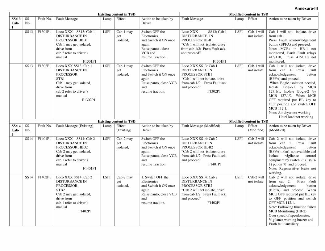
Annexure-III
Existing content in TSD Modified content in TSD
SS:13
Cab-
1
SS
No.
Fault No. Fault Message Lamp Effect Action to be taken by
Driver
Fault Message
Lamp Effect
Action to be taken by Driver
SS13 F1301P1 Loco XXX SS13: Cab 1
DISTURBANCE IN
PROCESSOR HBB1
Cab 1 may get isolated,
drive from
cab 2 refer to driver’s
manual
F1301P1
LSFI Cab-1 may
get
isolated,
Switch OFF the
Electronics
and Switch it ON once
again.
Raise panto , close
VCB and
resume Traction.
Loco XXX SS13: Cab 1
DISTURBANCE IN
PROCESSOR HBB1
“Cab 1 will not isolate, drive
from cab 1/2; Press Fault ack.
and proceed”
F1301P1
LSFI Cab-1 will
not isolate
Cab 1 will not isolate, drive
from cab 1
Press Fault acknowledgement
button (BPFA) and proceed.
Note: MCBs in HB-1 not
monitored, Earth Fault relays
415/110, fuse 415/110 not
monitored.
SS13 F1302P1 Loco XXX SS13: Cab 1
DISTURBANCE IN
PROCESSOR
STB1
Cab 1 may get isolated,
drive from
cab 2 refer to driver’s
manual
F1302P1
LSFI Cab-1 may
get
isolated,
Switch OFF the
Electronics
and Switch it ON once
again.
Raise panto, close VCB
and
resume traction.
Loco XXX SS13: Cab 1
DISTURBANCE IN
PROCESSOR STB1
“Cab 1 will not isolate, drive
from cab 1/2; Press Fault ack.
and proceed”
F1302P1
LSFI Cab-1 will
not isolate
Cab 1 will not isolate, drive
from cab 1. Press Fault
acknowledgement button
(BPFA) and proceed.
When Bogie isolation needed,
Isolate Bogie-1 by MCB
127.1/1, Isolate Bogie-2 by
MCB 127.1/2. When MCE
OFF required put BL key to
OFF position and switch OFF
MCB 112.1.
Note: Air dryer not working
Hotel load not working
Existing content in TSD Modified content in TSD
SS:14
Cab-
2
SS
No.
Fault No. Fault Message (Existing) Lamp Effect
(Existing)
Action to be taken by
Driver
Fault Message (Modified)
Lamp Effect
(Modified)
Action to be taken by Driver
(Modified)
SS14 F1401P1 Loco XXX SS14: Cab 2
DISTURBANCE IN
PROCESSOR HBB2
Cab 2 may get isolated,
drive from
cab 1 refer to driver’s
manual
F1401P1
LSFI Cab-2 may
get
isolated,
Switch OFF the
Electronics
and Switch it ON once
again.
Raise panto, close VCB
and
resume Traction.
Loco XXX SS14: Cab 2
DISTURBANCE IN
PROCESSOR HBB2
“Cab 2 will not isolate, drive
from cab 1/2; Press Fault ack.
and proceed”
F1401P1
LSFI Cab-2 will
not isolate
Cab 2 will not isolate, drive
from cab 2. Press Fault
acknowledgement button
(BPFA); Pan1 not available and
isolate vigilance control
equipment by switch 237.1(SB-
1) put on ‘0’ and proceed.
Note: Regenerative brake not
working.
SS14 F1402P1 Loco XXX SS14: Cab 2
DISTURBANCE IN
PROCESSOR
STB2
Cab 2 may get isolated,
drive from
cab 1 refer to driver’s
manual
F1402P1
LSFI Cab-2 may
get
isolated,
1. Switch OFF the
Electronics
and Switch it ON once
again.
Raise panto, close VCB
and
resume traction.
Loco XXX SS14: Cab 2
DISTURBANCE IN
PROCESSOR STB2
“Cab 2 will not isolate, drive
from cab 1/2; Press Fault ack.
and proceed”
F1402P1
LSFI Cab-2 will
not isolate
Cab 2 will not isolate, drive
from cab 2. Press Fault
acknowledgement button
(BPFA) and proceed. When
MCE OFF required put BL key
to OFF position and switch
OFF MCB 112.1.
Note: Following function failed
MCB Monitoring (HB-2)
Over speed of speedometer,
Vigilance warning buzzer and
Erath fault auxiliary.


![Directed writing [0500/0522] (paper 3, Part 1)](https://img.pdfslide.us/doc/110x75/56816039550346895dcf5b8e/directed-writing-05000522-paper-3-part-1.jpg)