Embed Size (px)
Citation preview
Fault Management on Manned Spacecraft From Design to Operations
Carlos Garcia-Galan
5/5/09

Agenda
• Fault Management dimensions
• Fault Management analysis
• Real-time Fault Management
• Learning from Real Failures
• Evolution of on-board Fault Management Approach

Fault Management Dimensions
• Fault Management is accomplished in several dimensions:– Spacecraft Robustness, redundancy and margins
– Subsystem Hardware, Firmware and Software capabilities for Failure Detection Isolation and Recovery (FDIR)
– System-Level FDIR
– Role of the Spacecraft Crew and Mission Control Center (MCC) in Fault Management
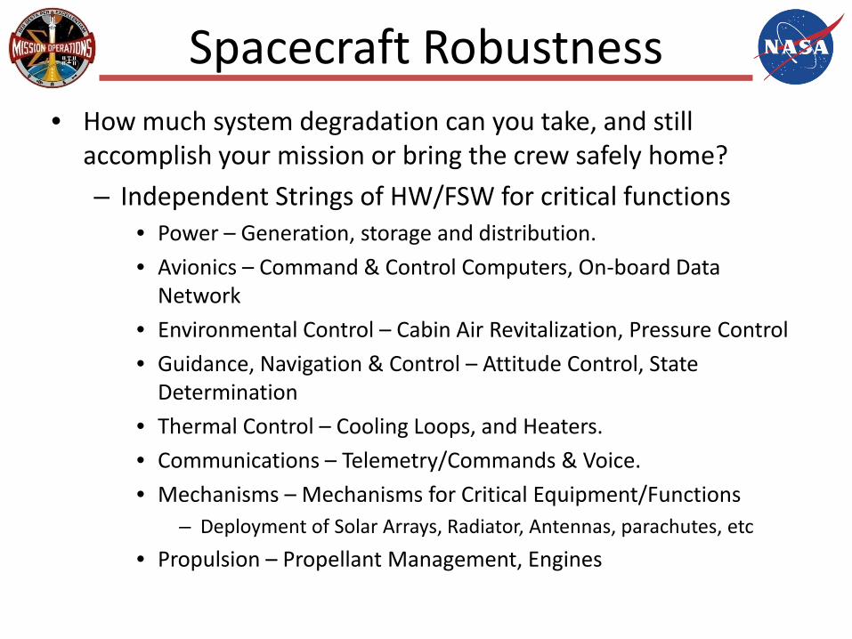
Spacecraft Robustness• How much system degradation can you take, and still
accomplish your mission or bring the crew safely home?
– Independent Strings of HW/FSW for critical functions• Power – Generation, storage and distribution.
• Avionics – Command & Control Computers, On-board Data Network
• Environmental Control – Cabin Air Revitalization, Pressure Control
• Guidance, Navigation & Control – Attitude Control, State Determination
• Thermal Control – Cooling Loops, and Heaters.
• Communications – Telemetry/Commands & Voice.
• Mechanisms – Mechanisms for Critical Equipment/Functions – Deployment of Solar Arrays, Radiator, Antennas, parachutes, etc
• Propulsion – Propellant Management, Engines
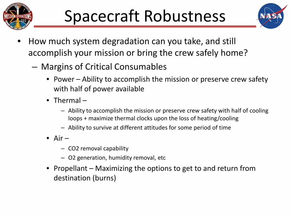
Spacecraft Robustness• How much system degradation can you take, and still
accomplish your mission or bring the crew safely home?
– Margins of Critical Consumables• Power – Ability to accomplish the mission or preserve crew safety
with half of power available
• Thermal –– Ability to accomplish the mission or preserve crew safety with half of cooling
loops + maximize thermal clocks upon the loss of heating/cooling
– Ability to survive at different attitudes for some period of time
• Air –– CO2 removal capability
– O2 generation, humidity removal, etc
• Propellant – Maximizing the options to get to and return from destination (burns)

Subsystem FDIR Responsibilities
• Expectations for Each Subsystem– Provide the necessary level of Subsystem FDIR over all components within Subsystem boundary
– Report all faults and health status– Evaluate sensor inputs to determine their validity and infer sensor health– Evaluate data inputs from subsystem components to determine validity and respond accordingly
• Key Objectives of Subsystem FDIR– To ensure safe operation of the Subsystem– To maintain functionality through available local redundancy– To prevent fault propagation beyond the subsystem boundary– Provide the necessary monitoring and functional tests as determined by safety analysis to identify and report latent faults or hazardous conditions and support:
• Situational awareness for crew and ground• Initiation of system-level and/or higher level recovery actions
6
DDCU Example
LAS62B_A
DCSU 2B
Z13BDDCU
LA2BDDCU
Z14BDDCU
LA1BDDCU
Z13BDDCU
LA2BDDCULA2BDDCU
Z13BDDCU
DCSU 4B
RBI 6
RBI 6
LA2B_A
LA2B_E LA2B_F LA2B_G LA2B_H
LA2B_B LA2B_C LA2B_DLA2B_A
LA2B_E LA2B_F LA2B_G LA2B_H
LA2B_B LA2B_C LA2B_DLA2B_A
LA2B_E LA2B_F LA2B_G LA2B_H
LA2B_B LA2B_C LA2B_D
LAD52B_A
CDH loadsTCS loads
MBSU
RBI 10
RBI 11
RBI 1
RBI 2
RBI 3
RBI 9
RBI 8
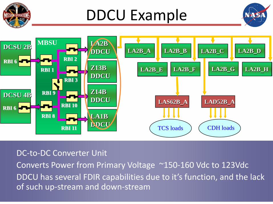
DC-to-DC Converter UnitConverts Power from Primary Voltage ~150-160 Vdc to 123VdcDDCU has several FDIR capabilities due to it’s function, and the lack of such up-stream and down-stream
February, 2009 8
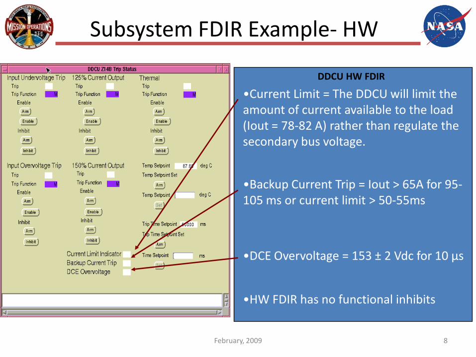
Subsystem FDIR Example- HW
DDCU HW FDIR
•Backup Current Trip = Iout > 65A for 95-105 ms or current limit > 50-55ms
•HW FDIR has no functional inhibits
•Current Limit = The DDCU will limit the amount of current available to the load (Iout = 78-82 A) rather than regulate the secondary bus voltage.
•DCE Overvoltage = 153 ± 2 Vdc for 10 µs
February, 2009 9
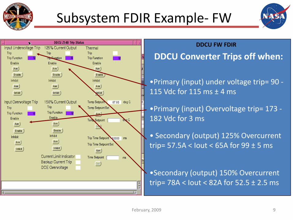
Subsystem FDIR Example- FW
DDCU FW FDIR
• Secondary (output) 125% Overcurrenttrip= 57.5A < Iout < 65A for 99 ± 5 ms
•Secondary (output) 150% Overcurrenttrip= 78A < Iout < 82A for 52.5 ± 2.5 ms
•Primary (input) under voltage trip= 90 -115 Vdc for 115 ms ± 4 ms
•Primary (input) Overvoltage trip= 173 -182 Vdc for 3 ms
DDCU Converter Trips off when:

February, 2009 10
Subsystem FDIR Example- FSW
DDCU FSW FDIR
• Secondary (output) Overvoltage trip: 129 Vdc for 6 sec = Converter Off
This FDIR action is designed to protect downstream loads sensitive to higher voltage, i.e. computers, electronics
• Overtemperature trip:
Conv Temp >190 deg F = Converter Off
PS Temp >175 deg F = Converter Off
Baseplate Temp >185 deg F = Converter Off
FSW Overtemp trip values are changeable
• Both FDIR actions (Voltage and Temperature protection) can be inhibited - see display.
System-Level FDIR
• Correlate subsystem-level information to detect faults that propagate across several subsystems (FDIR)
• Isolate to source subsystem, LRU or LRU component (lowest possible), from multiple subsystem fault indications (FDIR)
• Perform multi-system recovery actions required to mitigate the effects of a fault that affects multiple subsystems (FDIR)
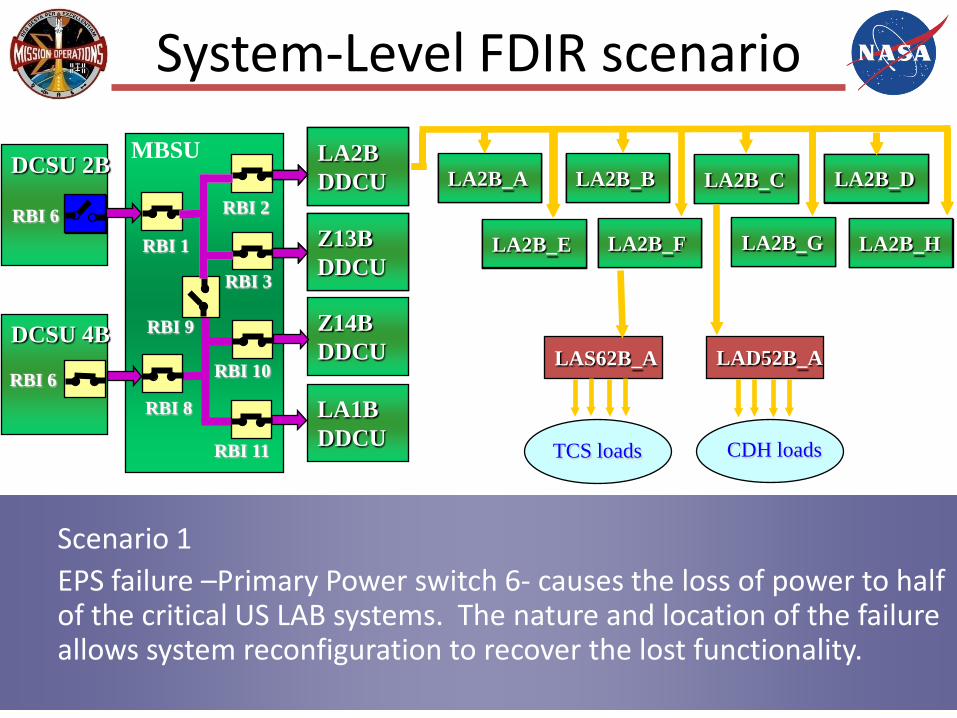
System-Level FDIR scenario
LAS62B_A
DCSU 2B
Z13BDDCU
LA2BDDCU
Z14BDDCU
LA1BDDCU
Z13BDDCU
LA2BDDCULA2BDDCU
Z13BDDCU
DCSU 4B
RBI 6
RBI 6
LA2B_A
LA2B_E LA2B_F LA2B_G LA2B_H
LA2B_B LA2B_C LA2B_DLA2B_A
LA2B_E LA2B_F LA2B_G LA2B_H
LA2B_B LA2B_C LA2B_DLA2B_A
LA2B_E LA2B_F LA2B_G LA2B_H
LA2B_B LA2B_C LA2B_D
LAD52B_A
CDH loadsTCS loads
MBSU
RBI 10
RBI 11
RBI 1
RBI 2
RBI 3
RBI 9
RBI 8
Scenario 1 EPS failure –Primary Power switch 6- causes the loss of power to half of the critical US LAB systems. The nature and location of the failure allows system reconfiguration to recover the lost functionality.
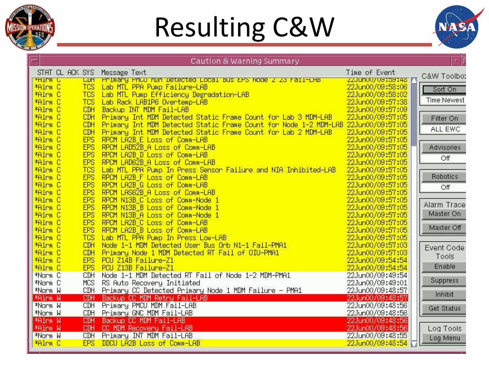
Resulting C&W
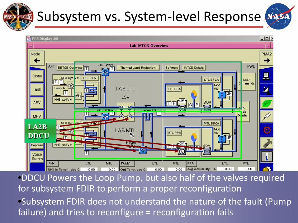
Subsystem vs. System-level Response
LA2BDDCU
•DDCU Powers the Loop Pump, but also half of the valves required for subsystem FDIR to perform a proper reconfiguration•Subsystem FDIR does not understand the nature of the fault (Pump failure) and tries to reconfigure = reconfiguration fails

System-Level FDIR scenario 2
Scenario 2 EPS failure –Primary Power switch 1- causes the loss of power to half of the critical US LAB systems. This failure prevents full system reconfiguration to regain lost functionality. Root cause, affected components and operator actions identified.
LAS62B_A
DCSU 2B
Z13BDDCU
LA2BDDCU
Z14BDDCU
LA1BDDCU
Z13BDDCU
LA2BDDCULA2BDDCU
Z13BDDCU
DCSU 4B
RBI 6
RBI 6
LA2B_A
LA2B_E LA2B_F LA2B_G LA2B_H
LA2B_B LA2B_C LA2B_DLA2B_A
LA2B_E LA2B_F LA2B_G LA2B_H
LA2B_B LA2B_C LA2B_DLA2B_A
LA2B_E LA2B_F LA2B_G LA2B_H
LA2B_B LA2B_C LA2B_D
LAD52B_A
CDH loadsTCS loads
MBSU
RBI 10
RBI 11
RBI 1
RBI 2
RBI 3
RBI 9
RBI 8
Fault Management Design
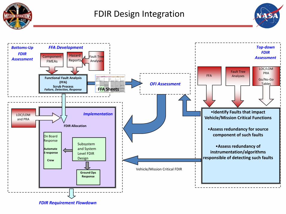
Integrated FDIR Design
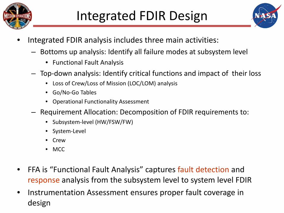
• Integrated FDIR analysis includes three main activities:– Bottoms up analysis: Identify all failure modes at subsystem level
• Functional Fault Analysis
– Top-down analysis: Identify critical functions and impact of their loss• Loss of Crew/Loss of Mission (LOC/LOM) analysis
• Go/No-Go Tables
• Operational Functionality Assessment
– Requirement Allocation: Decomposition of FDIR requirements to:• Subsystem-level (HW/FSW/FW)
• System-Level
• Crew
• MCC
• FFA is “Functional Fault Analysis” captures fault detection and response analysis from the subsystem level to system level FDIR
• Instrumentation Assessment ensures proper fault coverage in design

FFA Ins/Outs
Failure Modes & Effects Analysis
Architecture
LRU Lists
System/subsystem schematics
Sensors
Go-No/GO Tables
Failure ModePhysical Assumptions
Risk Probabilities
Avionics Processing Times
Vehicle Dynamic Timing
Mission Phases and Modes
Abort Condition List
Fault Trees & Hazards
LOC/LOM
• Failure description– Failure ID– Failure mode– Failure cause
• Effects– Component effects– Subsystem effects– System effects– Cx element effects
• Classification– Criticality (1, 2, 1R)– Abort condition (Y/N)
• Detection Criteria– Primary monitors– Secondary monitors– FDIR derived monitors– Detection Enabled/Disabled
• Response– Crew override– Design mitigation– Associated BIT– System/Subsystem response
required– Primary response– Secondary (backup) response– Tertiary response– Reporting criteria
Fault Detection Considerations
• Unambiguous fault detection instrumentation, vehicle behavior
Operational Considerations
• Nominal enable/ disable state of detections and responses
Fault Response Considerations
• Subsystem and System level FDIR responses
Self Test Considerations
• Built In/Start Up tests associated with FDIR
Enunciation Considerations
• Caution & Warning
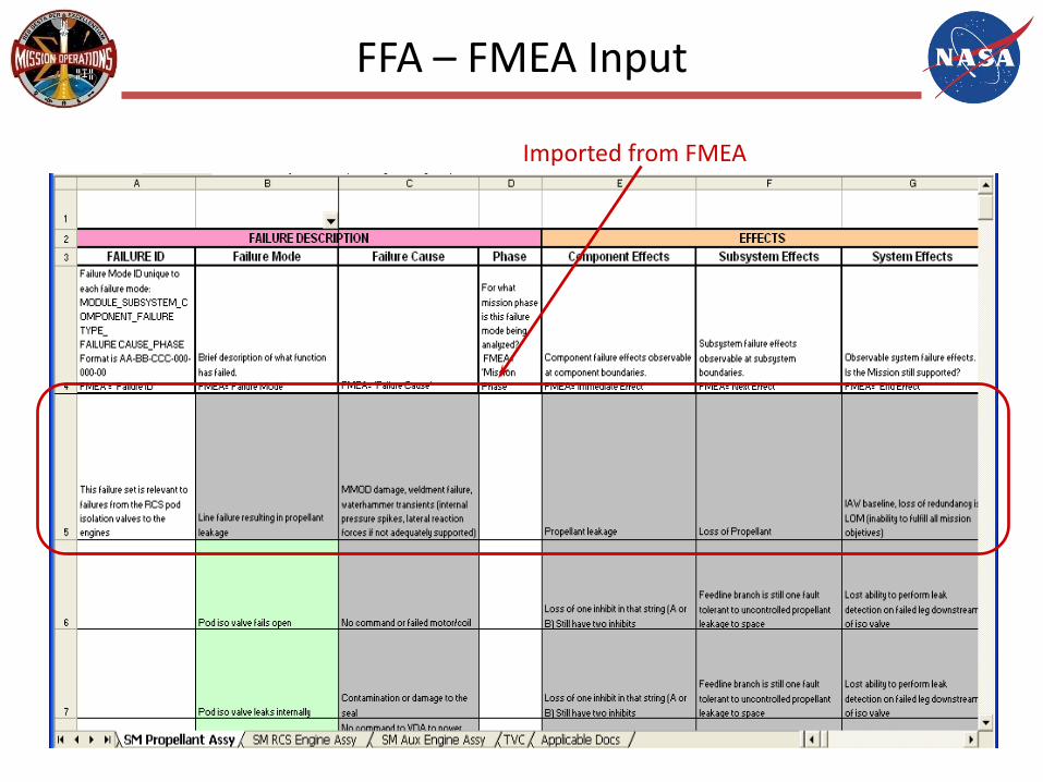
FFA – FMEA Input
Imported from FMEA
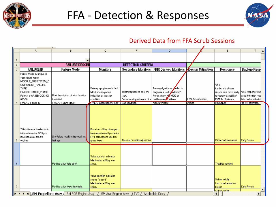
FFA - Detection & Responses
Derived Data from FFA Scrub Sessions

Relationship between FFA and OFI TDS
Component FMEAs
Hazard Reports
Functional Fault Analysis (FFA)
Scrub ProcessFailure, Detection, Response
Knowledge Capture
(present activity)
Fault Tree Analyses
Assessment Team
OPS, Safety, Systems Engineering, Subsystems
Sensors Data Channels
Consolidated Instrumentation List
Includes OFI & DFI
Instrumentation Team
DataChannelization
Board
Subsystems
InstrumentationChange Requests
Program Boards
Data Channel RelatedRecommendations
Recommended Solutions
Recommended Implementations
ApprovedInstrumentationChanges
PerformanceOperations
FDIR
FFA Sheets
Operational Flight Instrumentation (OFI) Assessment
FFA Development
FDIR Instrumentation Lists FFA Scrubs
FDIR RelatedRecommendations
FDIR Requirement Flowdown
FDIR Allocation
Ground Ops Response
On Board Response
Automated response
Crew
Implementation
Subsystem and System Level FDIR Design
LOC/LOM and PRA
FDIR Design Integration
Component FMEAs
Hazard Reports
Functional Fault Analysis (FFA)
Scrub ProcessFailure, Detection, Response
Bottoms-Up
FDIR Assessment
Fault Tree Analyses
FFA SheetsOFI Assessment
FFA Development
FDIR Requirement Flowdown
FDIR Allocation
Ground Ops Response
On Board Response
Automated response
Crew
Implementation
Subsystem and System Level FDIR Design
LOC/LOM and PRA
LOC/LOM PRA
Go/No-Go Tables
•Identify Faults that impact Vehicle/Mission Critical Functions
•Assess redundancy for source component of such faults
•Assess redundancy of instrumentation/algorithms
responsible of detecting such faults
Fault Tree AnalysesFFA
Top-down FDIR
Assessment
Vehicle/Mission Critical FDIR

FMEA/CIL Criticality Definition
• 1 - Single failure that could result in loss of life or vehicle.• 2 - Single failure that could result in loss of mission.• 1R# - Redundant hardware which, if all failed, could cause loss
of life or vehicle. A number is used to indicate the number of redundant paths or strings.
• 1S - Failure in a safety or hazard monitoring hardware item that could cause the system to fail to detect, combat, or operate when needed during a hazardous conditionk potentially resulting in loss of life or vehicle.
• 2R - Redundant hardware item which, if all failed, could cause a loss of mission.
• 3 - All other failures (3A, 3B, 3C)
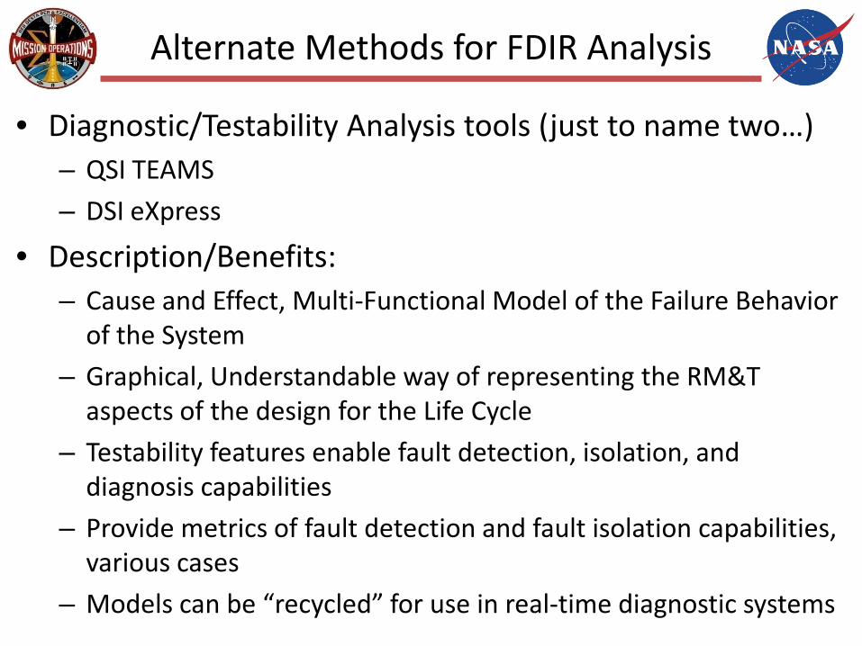
Alternate Methods for FDIR Analysis
• Diagnostic/Testability Analysis tools (just to name two…)– QSI TEAMS
– DSI eXpress
• Description/Benefits:– Cause and Effect, Multi-Functional Model of the Failure Behavior
of the System
– Graphical, Understandable way of representing the RM&T aspects of the design for the Life Cycle
– Testability features enable fault detection, isolation, and diagnosis capabilities
– Provide metrics of fault detection and fault isolation capabilities, various cases
– Models can be “recycled” for use in real-time diagnostic systems
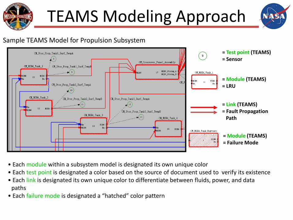
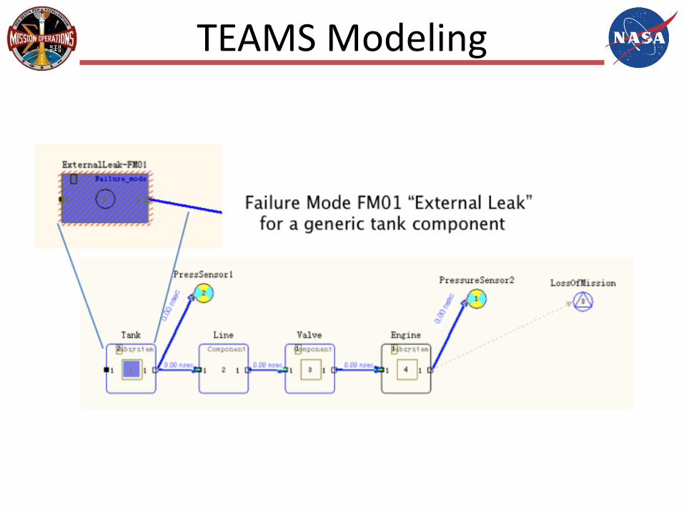
TEAMS Modeling Approach
= Test point (TEAMS)= Sensor
= Module (TEAMS)= LRU
= Link (TEAMS)= Fault Propagation
Path
= Module (TEAMS)= Failure Mode
Sample TEAMS Model for Propulsion Subsystem
• Each module within a subsystem model is designated its own unique color• Each test point is designated a color based on the source of document used to verify its existence• Each link is designated its own unique color to differentiate between fluids, power, and data
paths• Each failure mode is designated a “hatched” color pattern
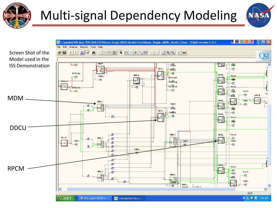
Multi-signal Dependency Modeling
Screen Shot of theModel used in the ISS Demonstration
MDM
DDCU
RPCM
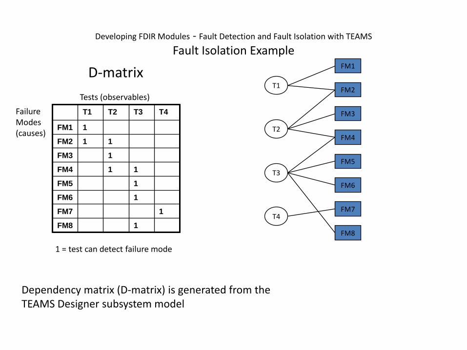
T1 T2 T3 T4
FM1 1
FM2 1 1
FM3 1
FM4 1 1
FM5 1
FM6 1
FM7 1
FM8 1
Failure Modes(causes)
Tests (observables)
D-matrix
1 = test can detect failure mode
FM2
FM1
FM3
FM4
FM7
FM8
FM5
FM6
T1
T4
T2
T3
Developing FDIR Modules - Fault Detection and Fault Isolation with TEAMS
Fault Isolation Example
Dependency matrix (D-matrix) is generated from the TEAMS Designer subsystem model
T1 T2 T3 T4
FM1 1
FM2 1 1
FM3 1
FM4 1 1
FM5 1
FM6 1
FM7 1
FM8 1
Failure Modes(causes)
Tests (observables)D-matrix
1 = test can detect failure mode
FM1
FM2
FM3
FM4
FM7
FM8
FM5
FM6
T1
T4
T2
T3
FAIL
FAIL
PASS
PASS
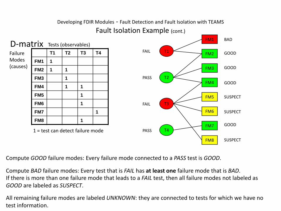
Compute GOOD failure modes: Every failure mode connected to a PASS test is GOOD.
GOOD
GOOD
GOOD
GOOD
FM2
FM3
FM4
FM7
FM1 BAD
Compute BAD failure modes: Every test that is FAIL has at least one failure mode that is BAD.If there is more than one failure mode that leads to a FAIL test, then all failure modes not labeled as GOOD are labeled as SUSPECT.
FM8
FM5
FM6
SUSPECT
SUSPECT
SUSPECT
All remaining failure modes are labeled UNKNOWN: they are connected to tests for which we have no test information.
Developing FDIR Modules - Fault Detection and Fault Isolation with TEAMS
Fault Isolation Example (cont.)
TEAMS Modeling

30
Testability Analysis
• Determine % Fault Detection & Isolation – if low, can redesign to add more sensors or others detection or inference means
• Identify General System’s metrics – Failure modes, Test points, etc
31
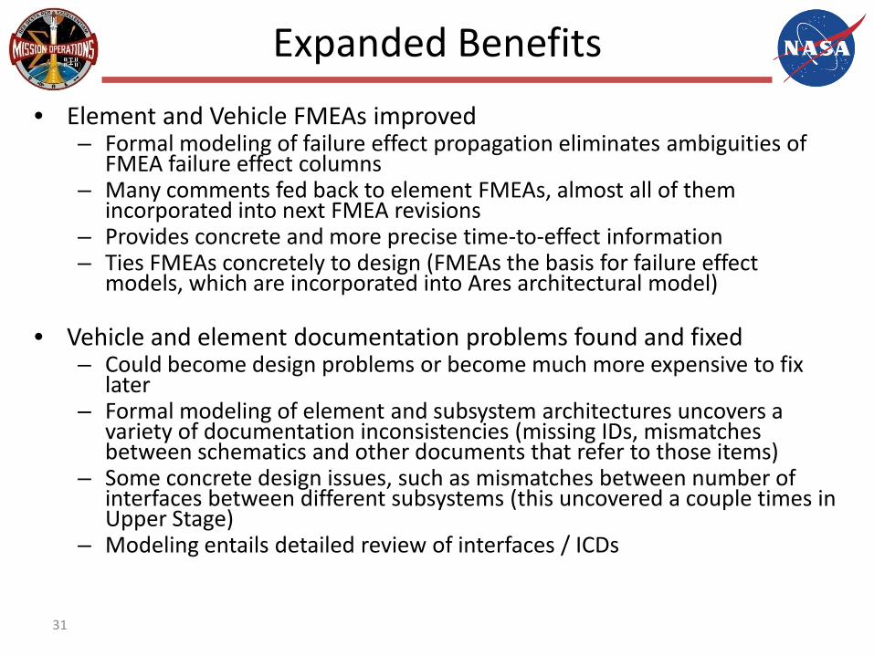
Expanded Benefits
• Element and Vehicle FMEAs improved– Formal modeling of failure effect propagation eliminates ambiguities of
FMEA failure effect columns– Many comments fed back to element FMEAs, almost all of them
incorporated into next FMEA revisions– Provides concrete and more precise time-to-effect information– Ties FMEAs concretely to design (FMEAs the basis for failure effect
models, which are incorporated into Ares architectural model)
• Vehicle and element documentation problems found and fixed– Could become design problems or become much more expensive to fix
later – Formal modeling of element and subsystem architectures uncovers a
variety of documentation inconsistencies (missing IDs, mismatches between schematics and other documents that refer to those items)
– Some concrete design issues, such as mismatches between number of interfaces between different subsystems (this uncovered a couple times in Upper Stage)
– Modeling entails detailed review of interfaces / ICDs
Real-Time Fault Management
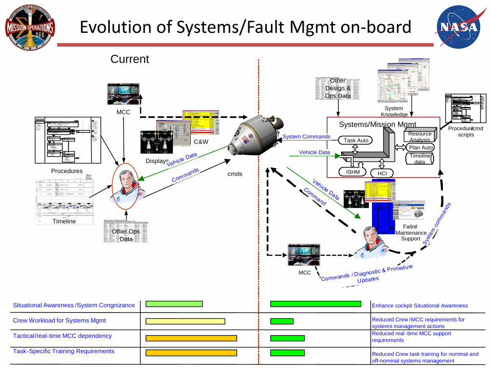
Evolution of Systems/Fault Mgmt on-board
C&W
Vehicle Data
System Commands
MCC
1The
primary tool
for
assessing C &W events is
the C &W Summary
on the PCS .
Time , text message field (on Alarm
Tool Bar ) , and Alarm
Trace are consid
ered suppleme
ntal . In some i
nstances the
information
provided may be
misleading . SPN
# xxx .2 Only use
event code
tools ( suppress
;
inhibit , or enable )
when
directed to do
so
by
MC
C or proce
dure .3Non Quick Response
refers to
the
follow on
proced
ures f
ound
in system
ODF books which are called out at the end of Quick
Respo
nse proced
ures .
C& wALARMHear
tone (s ) and
see
light (s )Nominal Config :
No
unacknowledged
C& W messages
in
alarm .Emergency ODF resides
in each module
and
is
near PCS and Russi an
laptop .
1Silence tone ( s )Any of the following
methods can be used :•On the
?CC
: Press the ACK pushbutton•
On the C &W Panel : Press
highest class illuminated button•On the Russi an Laptop : Click Sound
Mute icon on Events Display•
On the
PCS :
Select highest class illuminated button on Alarm
Tool
Bar ( and
cmd
Silence all Tones for p
re-CCS )
2 Identify Response Based Upon C &W Class
Has an Emergency class
event been annunciated ?
Has malfunction
occu
rred on
RS ?Has a Warning class
event been annunciated ?Has a Caution class
event been annunciated and / or a “Non Quick
Response” procedure been called from the
EMER ODF ?
3•
Repor
t to
MC
C.
4Assess Lab
and Node LightingAre
multiple
C &W
messages in alarm and
multiple GLAs within the
Lab and /or Node off ?
5Diagnose
EPS Failure•
Perform
Unknown EPS
Failure ( SODF :
EMER :
EPG ) , then :
6 Determine Order to Work
Warning Messages•
Address EPS Warning
messages first . •
If there are
multiple EPS
Warning messages ,
address
the message associated with
the highest tier EPS ORU . •
If there are no
EPS Warning me
s
sages , the
order does not matt
er .7
Determine Procedure
to
Execute
•Look up Warning
message
( SODF : EMER :
WARNING
TABLE ) .•Determine
corresponding proce
dure .
8•
Report to
MCC .
•Continue if
no voice .9
Execute
Warning Proce
dure•Perform
appropriate Warning
procedure
( SODF : EMER :
Group
Tab). •Execute
all called procedures in
Emergency ODF . Do not
go to called procedu
res inother ODF book
s .
4
2
Ye
sN
o
21
3
1
1
10
1
4
1
4 1
5
System Knowledge
Procedure/cmd scripts
Other Design & Ops Data
Enhance cockpit Situational Awareness
Reduced Crew /MCC requirements for systems management actionsReduced real -time MCC support requirements
Reduced Crew task training for nominal and off-nominal systems management
ISHM
Task AutoPlan Auto
ResourceAnalysis
Timelinedata
HCI
Systems/Mission Mgmt
Failre/Maintenance
Support
C&W
Current
cmds
1The primary tool
for assessing C &W events is the C& W Summary on the
PCS . Time , text message field ( on Alarm Tool Bar ) , and Alarm Trace
are considered supplemental . In some i nstances the information
provided may be misleading . SPN #xxx .
2 Only use event
code tools (suppress ; inhibit , or enable ) when directed to
do so by MCC or procedure .
3Non Quick Response refers
to the follow on procedures
found in system ODF
books which are called out
at the end of Quick Response
procedures .
C& wALARM
Hear tone ( s )
and see light ( s )
Nominal Config :No
unacknowledged C &W messages
in alarm .Emergency ODF
resides in each module and is near PCS and Russi an laptop .
1 Silence tone ( s )
Any of the following methods can be
used :• On the ? CC: Press the ACK
pushbutton•On the C &W Panel : Press highest class illuminated
button•On the Russi an Laptop : Click Sound Mute icon on Events
Display•On the
PCS :Select highest class illuminated button on Alarm
Tool Bar ( and cmdSilence all Tones for
pre - CCS )
2Identify Response Based Upon C &W
ClassHas an Emergency class event been
annunciated ?Has malfunction
occu
rred on
RS ?Has a Warning class event been
annunciated ?Has a Caution class event been
annunciated and / or a “Non Quick Response” procedure been
called from the EMER ODF ?
3• Report to MCC .
4 Assess Lab and Node Lighting
Are multiple
C& W messages in alarm
and multiple GLAs within the
Lab and / or Node off ?
5 Diagnose EPS Failure
•Perform Unknown
EPS Failure (SODF :
EMER : EPG ), then :
6Determine Order to
Work Warning Messages
•Address EPS
Warning messages first . •
If there are multiple
EPS Warning messages ,
address the message associated
with the highest tier EPS
ORU . •
If there are no EPS
Warning messages , the order does
not matter .
7Determine
Procedure to Execute•
Look up
Warning message ( SODF :
EMER : WARNING TABLE )
.•
Determine
corresponding procedure .
8• Report to MCC .•
Continue if no
voice .
9Execute
Warning Procedure•
Perform appropriate Warning procedure
( SODF : EMER :
Group Tab ). •
Execute all called procedures in Emergency
ODF . Do not go to
called procedures
inother ODF
books .
4
2
Yes
No
21
3
11
10
14
14
15
Displays
Timeline
Procedures
MCC
Other Ops Data
Situational Awareness /System Congnizance
Crew Workload for Systems Mgmt
Tactical/real-time MCC dependency
Task-Specific Training Requirements
On-board Fault Management relevance to Ops
• Mission Control Center (MCC) - Level of dependency of the spacecraft and crew on tactical/real-time MCC support during nominal and off-nominal operations. – This includes the size of the team required for real-time
operations, as well as mission preparation and planning.
• Crew Training - Training requirements associated with necessary crew involvement for nominal/routine system management, and response to off-nominal conditions. – If the crew is required to actively perform health
monitoring, FDIR, and nominal routine system control = significant task and skill training is required.
• Flight Product development - Development of flight procedures and other products required by the crew and Flight Control Team (FCT) to manage the system and operate the spacecraft during nominal and off-nominal operations.
On-board Fault Management relevance to Ops
• Engineering support - Dependency on engineering teams, outside of the FCT, to provide system expertise during nominal operations and support anomaly troubleshooting.
• Mission Planning - Detail required in pre-mission planning to support the execution of a nominal mission and provide sufficient margins for contingency operations. – This includes resource analysis, and timeline development,
thus on-board capabilities for resource management, or greater availability of resources, reduces granularity required in pre-mission planning.
Key Fault Management Elements
• Vehicle Instrumentation & Displays– Provide Crew and MCC insight into system performance, anomalies and
current system status– Enables identification and response to failures– Provides sufficient insight to perform the mission specified for the spacecraft
• Flight Data File– Contains nominal, malfunction and reference procedures for the Crew to
conduct their mission.– Malfunction procedures support Fault detection, Isolation and Recovery when
this actions are not performed by on-board systems
• Caution & Warning– Alerts the crew to system failures that require their attention– Information provided by aural tones, lights, and displayed information– Level of information provided by the C&W system determines the crew
response to the information.

C&W Message Classification
Caution and Warning Alert notification system for flight crew and ground that includes Emergencies, Cautions, Warnings, and Advisories.
Emergency (Class 1 event)
Any condition that threatens the life of the crew or vehicle and requires immediate action. Three specific conditions (event types) define the emergency class; fire/smoke, rapid change in cabin pressure and toxic atmosphere.
Warning (Class 2 event)
Any event that requires immediate correction to avoid loss of or major impact to the vehicle or potential loss of crew.
Caution (Class 3 event)
Any event that is not time critical in nature but further degradation has the potential to threaten the loss of crew, or the loss of redundant equipment such that subsequent failure could result in a Warning condition.
Advisory (Class 4 event)
A non Caution and Warning message which provides information about systems status and processes.
Fault Management on-board Orbiter
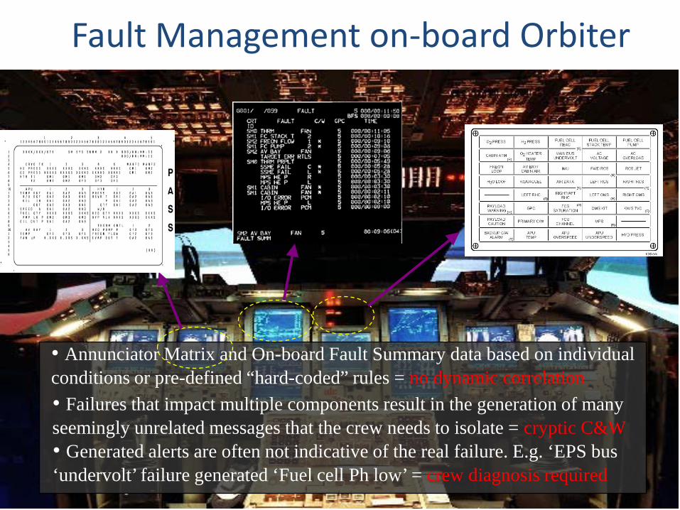
• Annunciator Matrix and On-board Fault Summary data based on individual conditions or pre-defined “hard-coded” rules = no dynamic correlation• Failures that impact multiple components result in the generation of many seemingly unrelated messages that the crew needs to isolate = cryptic C&W• Generated alerts are often not indicative of the real failure. E.g. ‘EPS bus ‘undervolt’ failure generated ‘Fuel cell Ph low’ = crew diagnosis required

Fault Management on-board ISS
1 The primary tool for assessing C&W events is the C&W Summary on the PCS. Time, text message field (on Alarm Tool Bar), and Alarm Trace are considered supplemental. In some instances the information provided may be misleading. SPN #xxx. 2 Only use event code tools (suppress; inhibit, or enable) when directed to do so by MCC or procedure. 3 Non Quick Response refers to the follow on procedures found in system ODF books which are called out at the end of Quick Response procedures.
C&wALARM
Hear tone(s) and see light(s)
Nominal Config: No unacknowledged C&W messages in alarm.
Emergency ODF resides in each module and is near PCS and Russian laptop.
1 Silence tone(s)
Any of the following methods can be used: • On the ПCC: Press the ACK pushbutton • On the C&W Panel: Press highest class illuminated button • On the Russian Laptop: Click Sound Mute icon on Events Display • On the PCS: Select highest class illuminated button on Alarm Tool
Bar (and cmd Silence all Tones for pre-CCS)
2 Identify Response Based Upon C&W Class
Has an Emergency class event been annunciated? Has malfunction occurred on RS? Has a Warning class event been annunciated? Has a Caution class event been annunciated and/or a “Non Quick Response” procedure been called from the EMER ODF?
3 • Report to MCC.
4 Assess Lab and Node Lighting
Are multiple C&W messages in alarm and multiple GLAs within the Lab and/or Node off?
5 Diagnose EPS Failure
• Perform Unknown EPS Failure (SODF: EMER: EPG), then:
6 Determine Order to Work Warning Messages
• Address EPS Warning messages first.
• If there are multiple EPS Warning messages, address the message associated with the highest tier EPS ORU.
• If there are no EPS Warning messages, the order does not matter.
7 Determine Procedure to Execute
• Look up Warning message (SODF: EMER: WARNING TABLE).
• Determine corresponding procedure.
8 • Report to MCC. • Continue if no voice.
9 Execute Warning Procedure
• Perform appropriate Warning procedure (SODF: EMER: Group Tab).
• Execute all called procedures in Emergency ODF. Do not go to called procedures in other ODF books.
4
2
Yes
No
2 1
3
11
10
14
14
15
Sensors “A” Sensors “B” Sensors “n”
Subsystem n
“n” Sensors
“B” Sensors
“A” Sensors
“n” FDIR
“B” FD
IR
“A” FD
IR
Subsystem BSubsystem A
•H&S driven from individual subsystem-level health mgmt data, not vehicle-level health state•C&W data only one “piece of the puzzle” to determine the nature of the failure, and system propagation•H&S data does not directly provide failure response information, or system impact severity
PCSSSC C&W
Diagnose
Respond
•Each C&W message has associated procedures for crew or ground execution. Diagnosis within procedures

Key FM Elements– Decision Support
• Decision Support Information– Generation of actionable information for the Crew or Flight Controllers– Required information to make a failure response decision– Typical information required:
• Affected Components - System components that have lost partial or all functionality as a consequence of the root cause failure.
– Power failure that also affects thermal control: all components that have lost power + all components that start getting hot.
• System-level impact - Components or functionality that performs critical functions and has been affected by, or is the root-cause failure.
– A power failure cuts power to 4 loads: light 1, light 2, light 3, and main air conditioning unit. Affected components are all four and system-level impact is the loss of air conditioning.
• Redundancy of Critical Components – Level of redundancy degradation of critical components
– In the Internal Measurement Unit (IMU) in the Shuttle, for example, the system is 2-fault tolerant, since there are 3 IMUs, and only one is necessary to perform the IMU system functions. Upon the loss of one IMU, the system would be 1-fault tolerant.
• Critical-to Information - A system is “Critical to” any component that if failed, will prevent the system from performing its functions.
– The IMU system is two-fault tolerant for individual IMU failures. If two IMUs have failed, then the IMU system is critical to the non-redundant components that keep the last IMU functioning.

Learning from System Anomalies - STS
• STS 93 Electrical Short During ascent– Seven seconds after lift-off, the Orbiter suffered a transient AC electrical short
circuit
– Failure Indications Onboard: ‘Fuel Cell pH’ message generated by the computer. This message occasionaly occurs during ascent as a transient condition.
– Root-cause: electrical short had momentarily dropped the AC bus voltage and a built-in self-check of the pH sensor had caused the message when the power was restored.
– The crew was unaware of the real issue and the impact to the the health of critical systems for ascent.
• Affected Components – equipment powered by shorted AC bus
• System impact – none
• Redundancy of critical components – 2 main engine controllers 0 Fault Tolerant to MEC, power and data
• Critical to: MEC, Power and data components for affect MECs
– Crew Situational awareness based on sysem indications - none

Learning from System Anomalies - ISS
• ISS US C&C Failure– STS-100/ISS 6A assembly mission in April 2001, the ISS
suffered failures within the hard drive mass storage system of each of the 3 Command and Control (C&C) flight computers over several days.
– Result: no command & control capability, no insight in system telemetry
– Factors that contributed to recovery:• The ISS architecture comprised of US and RS segments – RS
maintained critical capabilities• The Space Shuttle was docked to ISS – providing additional
comm capabilities and ATT control• Systems Management functions in the ISS architecture are
distributed – power generation, atmosphere control, attitude control, thermal
control) are allocated within the subsystem control, between HW, firmware, tier 2 and local tier 3 computers.
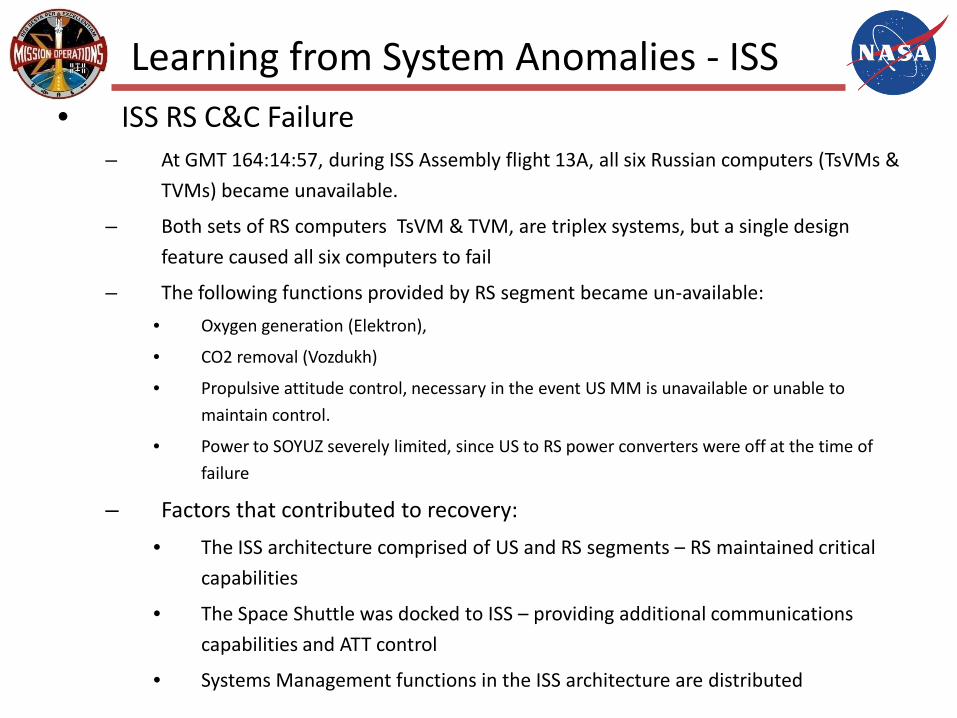
Learning from System Anomalies - ISS• ISS RS C&C Failure
– At GMT 164:14:57, during ISS Assembly flight 13A, all six Russian computers (TsVMs &
TVMs) became unavailable.
– Both sets of RS computers TsVM & ТVМ, are triplex systems, but a single design
feature caused all six computers to fail
– The following functions provided by RS segment became un-available:
• Oxygen generation (Elektron),
• CO2 removal (Vozdukh)
• Propulsive attitude control, necessary in the event US MM is unavailable or unable to
maintain control.
• Power to SOYUZ severely limited, since US to RS power converters were off at the time of
failure
– Factors that contributed to recovery:
• The ISS architecture comprised of US and RS segments – RS maintained critical
capabilities
• The Space Shuttle was docked to ISS – providing additional communications
capabilities and ATT control
• Systems Management functions in the ISS architecture are distributed
Questions/comments?
NASA-Johnson Space Center