Embed Size (px)
Citation preview

1414 IEEE TRANSACTIONS ON COMPUTER-AIDED DESIGN OF INTEGRATED CIRCUITS AND SYSTEMS, VOL. 20, NO. 12, DECEMBER 2001
Fault-Diagnosis-Based Technique for EstablishingRTL and Gate-Level Correspondences
Srivaths Ravi, Indradeep Ghosh, Member, IEEE, Vamsi Boppana, and Niraj K. Jha, Fellow, IEEE
Abstract—In this paper, we address an important problemassociated with hierarchical design flows (termed the mappingproblem): identifying correspondences between a signal in ahigh-level specification and a net in its lower level implemen-tation. Conventional techniques use shared names to associatea signal with a net whenever possible. However, given that asynthesis flow may not preserve names, such a solution is notuniversally applicable. This work provides a robust frameworkfor establishing register-transfer level (RTL) signal to gate-levelnet correspondences for a given design. Our technique exploitsthe observation that circuit diagnosis provides a convenient meansfor locating faults in a gate-level network. Since our problemrequires locating gate-level nets corresponding to RTL signals,we formulate the mapping problem as a query whose solution isprovided by a circuit diagnosis engine. Our experimental workwith industrial designs for many mapping cases shows that oursolution to the mapping problem is 1) fast and 2) precise inidentifying the gate-level equivalents (the number of nets returnedby our mapping engine for a query is typically one or two even fordesigns with tens of thousands of VHDL lines).
Index Terms—Fault diagnosis, incremental synthesis, signal cor-respondences, verification.
I. INTRODUCTION
C IRCUIT designs are typically represented at severallevels of abstraction such as a geometric description of
the layout, a gate-level netlist, or a higher level specification ina hardware description language like VHDL. Synthesis toolsyield a hardware design by gradually refining a high-levelspecification of the design [register-transfer level (RTL)] to alower level implementation (gate level or layout) using a seriesof mapping and optimization phases.
Several applications in the top-down design approach requiredesigners to identify a portion of the gate-level implementationthat corresponds to a section of its RTL specification. For ex-ample, “design bugs” and “late-arriving functionality” force in-cremental changes to a specification and the gate-level imple-mentation synthesized from it. Since the designer usually hassome investment in the original implementation [1], it is de-sirable to reuse as much of that implementation as possible.This has inspired the Synopsys engineering change order (ECO)compiler [2], which uses the gate-level incremental synthesis
Manuscript received August 7, 2000; revised June 1, 2001. This paper wasrecommended by Associate Editor S. Reddy.
S. Ravi is with the NEC Computer and Communications Research Laborato-ries, Princeton, NJ 08540 USA.
I. Ghosh and V. Boppana are with the Fujitsu Laboratories of America, Sun-nyvale, CA 94086 USA.
N. K. Jha is with the Department of Electrical Engineering, Princeton Uni-versity, Princeton, NJ 08544 USA.
Publisher Item Identifier S 0278-0070(01)10637-8.
techniques (specifications and implementations are gate-levelnetworks) [1], [3], [4] to carry out engineering changes (ECs) toRTL specifications. The methodology takes the logical descrip-tions synthesized from the original and modified RTL specifi-cations and identifies equivalent logic regions for reuse throughintensive formal verification techniques. In this way, the newimplementation is gradually modified to inherit as much of theoriginal netlist structure as possible.
A clear disadvantage of the above approach is that a signifi-cant portion of the time is spent on identifying the large portionsof the design that are unlikely to change (formal verificationof industrial designs typically takes several hours to days forcompletion). An alternative way to make incremental synthesiswork would be to provide a viable means for identifying theap-propriateportion that changes in the gate-level implementationdue to a modification of the RTL specification. We can clearlydo this if we can establish a correspondence between a signalof interest in the RTL specification and a net or set of nets in itsgate-level implementation. This is themapping problemtackledin this paper.
Another application that critically requires an efficient solu-tion to the mapping problem is RTL to gate-level verification.This is required to improve the performance of the core ver-ification engine that compares a “mapped” (low-synthesis ef-fort) gate-level netlist obtained from the RTL circuit with theimplementation netlist. Such verification techniques have beenknown to scale well to large designs only when a large numberof internal correspondences can be established between the twonetlists [5]. Therefore, a technique that efficiently maps RTLsignals to gate-level nets in the implementation netlist wouldsignificantly improve their overall performance.
From the above discussion, we see that a solution to the map-ping problem has the potential to affect applications as diverseas incremental synthesis and design verification. The main bot-tleneck that has confronted researchers so far is the absence of aclear way for identifying the gate-level net corresponding to anRTL signal. Traditional approaches have relied on using sharednames to relate signals and nets, whenever possible. However,this approach has a major disadvantage since names are usuallynot preserved across the multiple phases that make up a syn-thesis framework. This is true not only when multiple vendorscater to a synthesis framework, but also when a single vendoris responsible. Even otherwise, finding an exact solution to themapping problem may be practically impossible. For example,a signal in the VHDL specification may not appear as a signalin the gate-level network due to optimizations such as constantpropagation, technology mapping, etc. Given that an applica-tion such as EC restructures the logic around an RTL signal of
0278–0070/01$10.00 © 2001 IEEE
RAVI et al.: FAULT-DIAGNOSIS -BASED TECHNIQUE 1415
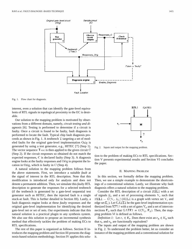
Fig. 1. Flow chart for diagnosis.
interest, even a solution that can identify the gate-level equiva-lents of RTL signals in topological proximity to the EC is desir-able.
Our solution to the mapping problem is motivated by obser-vations from a different domain, namely,circuit testing and di-agnosis[6]. Testing is performed to determine if a circuit isfaulty. Once a circuit is found to be faulty, fault diagnosis isperformed to locate the fault. Typical chip fault diagnosis pro-ceeds as shown in Fig. 1. A testbenchtargeting a set of mod-eled faults for the original gate-level implementation isgenerated by using a test generator, e.g., HITEC [7] (Step 1).The vector sequence is then applied to the given circuit(Step 2). If the circuit responses so obtained do not match theexpected responses,is declared faulty (Step 3). A diagnosisengine looks at the faulty responses and to pinpoint the lo-cation in , which is faulty in (Step 4).
A natural solution to the mapping problem follows fromthe above statements. First, we introduce a suitablefault atthe signal of interest in the RTL description. Note that thismodification is introduced only for analysis and does notdenote a permanent addition. Then, we simulate thisfaultyRTLdescription to generate the responses for a selected testbench(if the testbench is generated by a gate-level sequential testgenerator such as HITEC, then the injected fault is a singlestuck-at fault. This is further detailed in Section III). Lastly, afault diagnosis engine looks at thesefaulty responses and theoriginal gate-level implementation for identifying the desiredgate-level net or set of nets. Our experiments indicate that thisnatural solution is a practical plugin to any synthesis system.We also use this solution to propose an incremental synthesismethod that effectively tackles the problem of making ECs toRTL specifications.
The rest of this paper is organized as follows. Section II in-troduces the mapping problem and Section III presents the diag-nosis-based solution methodology. Section IV applies this solu-
Fig. 2. Inputs and output for the mapping problem.
tion to the problem of making ECs to RTL specifications. Sec-tion V presents experimental results and Section VI concludesthe paper.
II. M APPING PROBLEM
In this section, we formally define the mapping problem.Then, we use a simple example to demonstrate the shortcom-ings of a conventional solution. Lastly, we illustrate why faultdiagnosis offers a natural solution to the mapping problem.
Consider the RTL description of a circuit with a setof signals and a set of processing elements such that
( is a graph with vertex set andedge set ). Let be the gate-level implementation syn-thesized from with a set of gates and a set of intercon-nections such that . Then, the map-ping problem is defined as follows.
Definition 1: Let . Does there exist an suchthat and are functionally equivalent?
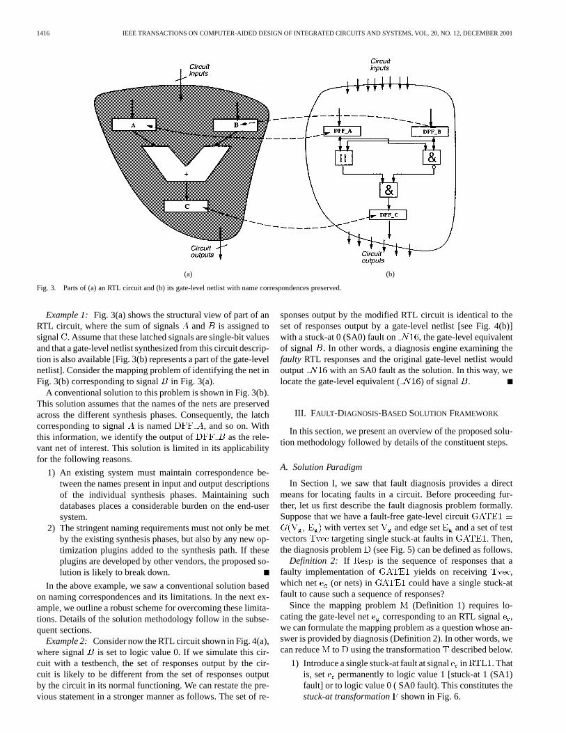
The inputs and output of the mapping problem are shownin Fig. 2. To understand the problem better, let us consider aninstance of the mapping problem and a conventional solution forit.
1416 IEEE TRANSACTIONS ON COMPUTER-AIDED DESIGN OF INTEGRATED CIRCUITS AND SYSTEMS, VOL. 20, NO. 12, DECEMBER 2001
(a) (b)
Fig. 3. Parts of (a) an RTL circuit and (b) its gate-level netlist with name correspondences preserved.
Example 1: Fig. 3(a) shows the structural view of part of anRTL circuit, where the sum of signals and is assigned tosignal . Assume that these latched signals are single-bit valuesand that a gate-level netlist synthesized from this circuit descrip-tion is also available [Fig. 3(b) represents a part of the gate-levelnetlist]. Consider the mapping problem of identifying the net inFig. 3(b) corresponding to signal in Fig. 3(a).
A conventional solution to this problem is shown in Fig. 3(b).This solution assumes that the names of the nets are preservedacross the different synthesis phases. Consequently, the latchcorresponding to signal is named , and so on. Withthis information, we identify the output of as the rele-vant net of interest. This solution is limited in its applicabilityfor the following reasons.
1) An existing system must maintain correspondence be-tween the names present in input and output descriptionsof the individual synthesis phases. Maintaining suchdatabases places a considerable burden on the end-usersystem.
2) The stringent naming requirements must not only be metby the existing synthesis phases, but also by any new op-timization plugins added to the synthesis path. If theseplugins are developed by other vendors, the proposed so-lution is likely to break down.
In the above example, we saw a conventional solution basedon naming correspondences and its limitations. In the next ex-ample, we outline a robust scheme for overcoming these limita-tions. Details of the solution methodology follow in the subse-quent sections.
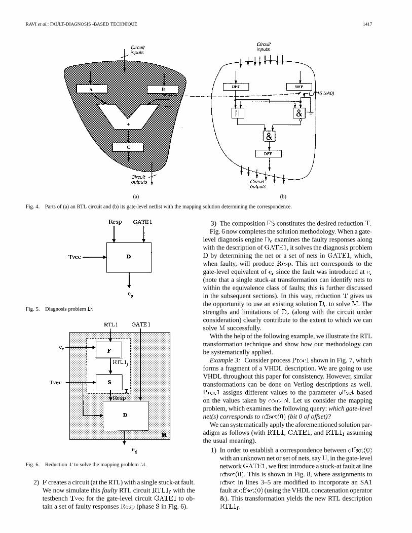
Example 2: Consider now the RTL circuit shown in Fig. 4(a),where signal is set to logic value 0. If we simulate this cir-cuit with a testbench, the set of responses output by the cir-cuit is likely to be different from the set of responses outputby the circuit in its normal functioning. We can restate the pre-vious statement in a stronger manner as follows. The set of re-
sponses output by the modified RTL circuit is identical to theset of responses output by a gate-level netlist [see Fig. 4(b)]with a stuck-at 0 (SA0) fault on , the gate-level equivalentof signal . In other words, a diagnosis engine examining thefaulty RTL responses and the original gate-level netlist wouldoutput with an SA0 fault as the solution. In this way, welocate the gate-level equivalent ( ) of signal .
III. FAULT-DIAGNOSIS-BASED SOLUTION FRAMEWORK
In this section, we present an overview of the proposed solu-tion methodology followed by details of the constituent steps.
A. Solution Paradigm
In Section I, we saw that fault diagnosis provides a directmeans for locating faults in a circuit. Before proceeding fur-ther, let us first describe the fault diagnosis problem formally.Suppose that we have a fault-free gate-level circuit
with vertex set and edge set and a set of testvectors targeting single stuck-at faults in . Then,the diagnosis problem (see Fig. 5) can be defined as follows.
Definition 2: If is the sequence of responses that afaulty implementation of yields on receiving ,which net (or nets) in could have a single stuck-atfault to cause such a sequence of responses?
Since the mapping problem (Definition 1) requires lo-cating the gate-level net corresponding to an RTL signal,we can formulate the mapping problem as a question whose an-swer is provided by diagnosis (Definition 2). In other words, wecan reduce to using the transformation described below.
1) Introduce a single stuck-at fault at signalin . Thatis, set permanently to logic value 1 [stuck-at 1 (SA1)fault] or to logic value 0 ( SA0 fault). This constitutes thestuck-at transformation shown in Fig. 6.
RAVI et al.: FAULT-DIAGNOSIS -BASED TECHNIQUE 1417
(a) (b)
Fig. 4. Parts of (a) an RTL circuit and (b) its gate-level netlist with the mapping solution determining the correspondence.
Fig. 5. Diagnosis problemD.
Fig. 6. ReductionT to solve the mapping problemM.
2) creates a circuit (at the RTL) with a single stuck-at fault.We now simulate thisfaulty RTL circuit with thetestbench for the gate-level circuit to ob-tain a set of faulty responses (phase in Fig. 6).
3) The composition constitutes the desired reduction.Fig. 6 now completes the solution methodology. When a gate-
level diagnosis engine examines the faulty responses alongwith the description of , it solves the diagnosis problem
by determining the net or a set of nets in , which,when faulty, will produce . This net corresponds to thegate-level equivalent of since the fault was introduced at(note that a single stuck-at transformation can identify nets towithin the equivalence class of faults; this is further discussedin the subsequent sections). In this way, reductiongives usthe opportunity to use an existing solution to solve . Thestrengths and limitations of (along with the circuit underconsideration) clearly contribute to the extent to which we cansolve successfully.
With the help of the following example, we illustrate the RTLtransformation technique and show how our methodology canbe systematically applied.
Example 3: Consider process shown in Fig. 7, whichforms a fragment of a VHDL description. We are going to useVHDL throughout this paper for consistency. However, similartransformations can be done on Verilog descriptions as well.
assigns different values to the parameter basedon the values taken by . Let us consider the mappingproblem, which examines the following query:which gate-levelnet(s) corresponds to (bit 0 of offset)?
We can systematically apply the aforementioned solution par-adigm as follows (with , , and assumingthe usual meaning).
1) In order to establish a correspondence betweenwith an unknown net or set of nets, say, in the gate-levelnetwork , we first introduce a stuck-at fault at line
. This is shown in Fig. 8, where assignments toin lines 3–5 are modified to incorporate an SA1
fault at (using the VHDL concatenation operator&). This transformation yields the new RTL description
.
1418 IEEE TRANSACTIONS ON COMPUTER-AIDED DESIGN OF INTEGRATED CIRCUITS AND SYSTEMS, VOL. 20, NO. 12, DECEMBER 2001
Fig. 7. Fragment of VHDL code calledEx1.
Fig. 8. Example of the stuck-at transformation:o�set(0) in Ex1 set to 1.
2) Next, given the gate-level network , say with sixinputs and eight outputs, an automatic test pattern gen-eration tool is run to obtain a testbench that tar-gets all the single stuck-at faults in . Suppose that
is the vector sequence given below
(1)
We now simulate with to get the outputresponses . Suppose that is as follows:
(2)
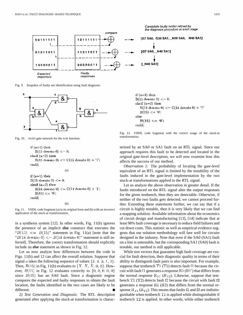
3) A diagnosis engine now accepts and as itsinputs. A simple way of looking at the diagnosis proce-dure is to associate a lookup structure that successivelyprunes the list of candidate faulty nets as it sequentiallyexamines both the expected and faulty responses. This isillustrated in Fig. 9. Suppose that we have an initial listof four candidate faults at the end of the first step asfollows:
(3)
The next comparison of responses prunes to. Diagnosis finally outputs
with a unique member . This means thatin is the faulty gate-level net that could
have produced the computed responses . Or, isthe desired gate-level equivalent of RTL signal .
Note that fault diagnosis (Step 3 in the above example) can bedone in many ways. Static techniques [8] use precomputed in-formation in the form of fault dictionaries to match the faulty re-sponses produced by the defective circuits. Dynamic techniques[9] diagnose the fault behavior of the circuit while the test set isapplied. More recently, integrated techniques use small amountsof precomputed information in tandem with dynamic algorithmsto perform efficient fault location [10].
B. Reduction—A Closer Look
In this section, we examine the individual steps of the reduc-tion in greater detail. First, we examine stuck-at transformationsand then discuss the test generation and diagnosis phases of thesolution.
1) Stuck-At Transformations:The stuck-at transformationthat introduces an SA0 or an SA1 fault at an RTL signal forsubsequent processing can be formally defined as follows.
Definition 3: Thestuck-at transformationfor an RTL signalmodifies all assignments toso that takes a constant value,
i.e., either logic 0 (for an SA0 transformation) or logic 1 (for anSA1 transformation).
In many cases, we can apply either the SA0 transformationor the SA1 transformation (Example 3) to find a solution tothe mapping problem. However, in some cases, we may haveto use both the transformations. This is because the precisionwith which diagnosis can identify a gate-level net is limited bythe faults to which a fault on that gate-level net is equivalent. Forexample, consider theNAND gate network for anXOR functionof two variables shown in Fig. 10 [11]. The classical examplefor equivalence is that line and line are indistin-guishable because they produce the same faulty responses forall input vectors. In fact, the equivalence class containingis . Likewise, the equiva-lence class containing is .
Extending the above example to the mapping problem, wecan see that if line is the desired mapping solution and theRTL stuck-at transformation is actually targeting , thenour solution will be accurate to the resolution level of (ele-ments of are indistinguishable by definition). Similarly, if weuse only the RTL SA1 transformation that is actually targeting
, then our solution will be accurate to the resolution levelof . However, if we use both the transformations and com-pare the results, we find that the only net identified by both thetransformations is net (in other words, the intersection ofand finds the net faulty in both and , which is ). In thisway, application of both the SA0 and SA1 transformations at theRTL [so as to target SA0 and SA1 faults on the correspondinggate-level net(s)] improves the accuracy of the mapping solu-tion.
The stuck-at transformation is a simple and powerful tool thatis applicable toanysignal in the VHDL description of a circuitirrespective of the language constructs used. It can be appliedto any RTL signal that is expressible as a bit or bit-vector datatype. The next example illustrates a typical instance of how thistransformation can be incorrectly applied and the subsequentside-effects.
Example 4 (Latch Inference Problem):Consider, for ex-ample, the VHDL conditional construct shown in Fig. 11(a)and the problem of applying an SA0 transformation to .Direct modification of the construct to incorporate a perma-nent logic 0 at preserves the assignment inthe if portion while modifying the assignment in theelseifportion. This is shown in Fig. 11(b). However, the indicatedmodifications do not completely achieve the objective ofintroducing logic-0 settings on all assignments to thesignal. This is because of potential implicit latch inferences
RAVI et al.: FAULT-DIAGNOSIS -BASED TECHNIQUE 1419
Fig. 9. Snapshot of faulty net identification using fault diagnosis.
Fig. 10. NAND gate network for theXOR function.
(a)
(b)
Fig. 11. VHDL code fragment (a) in its original form and (b) with an incorrectapplication of the stuck-at transformation.
in a synthesis system [12]. In other words, Fig. 11(b) ignoresthe presence of an implicitelse construct that executes the“ ” statement in Fig. 11(a) [note that the“ ” statement is still in-ferred]. Therefore, the correct transformation should explicitlyinclude anelsestatement as shown in Fig. 12.
Let us now analyze how differences between the code inFigs. 11(b) and 12 can affect the overall solution. Suppose thatsignal takes the following sequence of values .Then, in Fig. 11(b) evaluates to . How-ever, in Fig. 12 evaluates correctly tosince has an SA0 fault. Since a diagnostic enginecompares the expected and faulty responses to obtain the faultlocation, the faults identified in the two cases are likely to bedifferent.
2) Test Generation and Diagnosis:The RTL descriptiongenerated after applying the stuck-at transformation is charac-
Fig. 12. VHDL code fragment with the correct usage of the stuck-attransformation.
terized by an SA0 or SA1 fault on an RTL signal. Since ourapproach requires this fault to be detected and located in theoriginal gate-level description, we will now examine how thisaffects the success of our method.
Observation 1: The probability of locating the gate-levelequivalent of an RTL signal is limited by the testability of thefaults induced in the gate-level implementation by the twostuck-at transformations applied to the RTL signal.
Let us analyze the above observation in greater detail. If thefaults introduced on the RTL signal alter the output responsesfor the given testbench, then they are detectable. Otherwise, ifneither of the two faults gets detected, we cannot proceed fur-ther. Extending these statements further, we can say that if acircuit is highly testable, then it is very likely that we can finda mapping solution. Available information about the economicsof circuit design and manufacturing [13], [14] indicate that atleast 98% fault coverage is necessary to reduce field failures andcut down costs. This statistic as well as empirical evidence sug-gests that our solution methodology will fare well for circuitsdesigned in the industry. Note that even if the SA0 (SA1) faulton a line is untestable, but the corresponding SA1 (SA0) fault istestable, our method is still applicable.
While test vectors that guarantee high fault coverage are cru-cial for fault detection, their diagnostic quality in terms of theirability to distinguish fault pairs is also important. For example,suppose that testbench ( ) detects fault because the cir-cuit with fault generates a response ( ) that differs fromthe normal response ( ). Likewise, suppose that test-bench ( ) detects fault because the circuit with faultgenerates a response ( ) that differs from the normal re-sponse ( ). This means that faults and are indistin-guishable when testbench is applied while distinguishable iftestbench is applied. In other words, while either testbench
1420 IEEE TRANSACTIONS ON COMPUTER-AIDED DESIGN OF INTEGRATED CIRCUITS AND SYSTEMS, VOL. 20, NO. 12, DECEMBER 2001
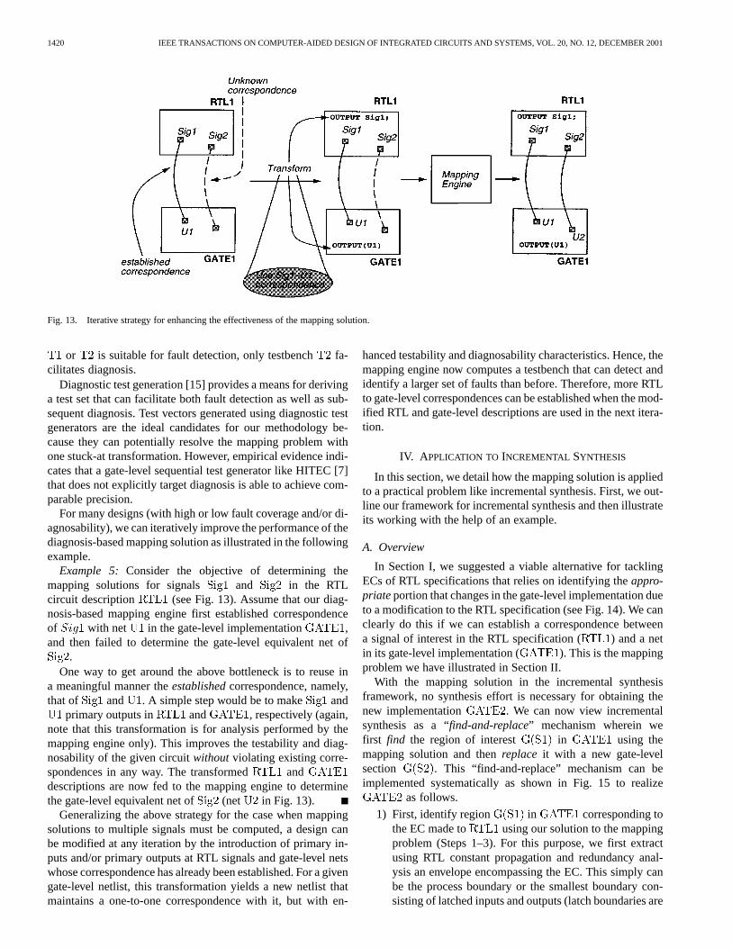
Fig. 13. Iterative strategy for enhancing the effectiveness of the mapping solution.
or is suitable for fault detection, only testbench fa-cilitates diagnosis.
Diagnostic test generation [15] provides a means for derivinga test set that can facilitate both fault detection as well as sub-sequent diagnosis. Test vectors generated using diagnostic testgenerators are the ideal candidates for our methodology be-cause they can potentially resolve the mapping problem withone stuck-at transformation. However, empirical evidence indi-cates that a gate-level sequential test generator like HITEC [7]that does not explicitly target diagnosis is able to achieve com-parable precision.
For many designs (with high or low fault coverage and/or di-agnosability), we can iteratively improve the performance of thediagnosis-based mapping solution as illustrated in the followingexample.
Example 5: Consider the objective of determining themapping solutions for signals and in the RTLcircuit description (see Fig. 13). Assume that our diag-nosis-based mapping engine first established correspondenceof with net in the gate-level implementation ,and then failed to determine the gate-level equivalent net of
.One way to get around the above bottleneck is to reuse in
a meaningful manner theestablishedcorrespondence, namely,that of and . A simple step would be to make and
primary outputs in and , respectively (again,note that this transformation is for analysis performed by themapping engine only). This improves the testability and diag-nosability of the given circuitwithoutviolating existing corre-spondences in any way. The transformed anddescriptions are now fed to the mapping engine to determinethe gate-level equivalent net of (net in Fig. 13).
Generalizing the above strategy for the case when mappingsolutions to multiple signals must be computed, a design canbe modified at any iteration by the introduction of primary in-puts and/or primary outputs at RTL signals and gate-level netswhose correspondence has already been established. For a givengate-level netlist, this transformation yields a new netlist thatmaintains a one-to-one correspondence with it, but with en-
hanced testability and diagnosability characteristics. Hence, themapping engine now computes a testbench that can detect andidentify a larger set of faults than before. Therefore, more RTLto gate-level correspondences can be established when the mod-ified RTL and gate-level descriptions are used in the next itera-tion.
IV. A PPLICATION TO INCREMENTAL SYNTHESIS
In this section, we detail how the mapping solution is appliedto a practical problem like incremental synthesis. First, we out-line our framework for incremental synthesis and then illustrateits working with the help of an example.
A. Overview
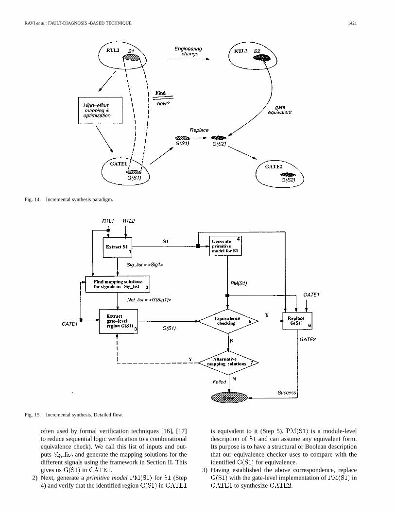
In Section I, we suggested a viable alternative for tacklingECs of RTL specifications that relies on identifying theappro-priateportion that changes in the gate-level implementation dueto a modification to the RTL specification (see Fig. 14). We canclearly do this if we can establish a correspondence betweena signal of interest in the RTL specification ( ) and a netin its gate-level implementation ( ). This is the mappingproblem we have illustrated in Section II.
With the mapping solution in the incremental synthesisframework, no synthesis effort is necessary for obtaining thenew implementation . We can now view incrementalsynthesis as a “find-and-replace” mechanism wherein wefirst find the region of interest in using themapping solution and thenreplace it with a new gate-levelsection . This “find-and-replace” mechanism can beimplemented systematically as shown in Fig. 15 to realize
as follows.
1) First, identify region in corresponding tothe EC made to using our solution to the mappingproblem (Steps 1–3). For this purpose, we first extractusing RTL constant propagation and redundancy anal-ysis an envelope encompassing the EC. This simply canbe the process boundary or the smallest boundary con-sisting of latched inputs and outputs (latch boundaries are
RAVI et al.: FAULT-DIAGNOSIS -BASED TECHNIQUE 1421
Fig. 14. Incremental synthesis paradigm.
Fig. 15. Incremental synthesis. Detailed flow.
often used by formal verification techniques [16], [17]to reduce sequential logic verification to a combinationalequivalence check). We call this list of inputs and out-puts and generate the mapping solutions for thedifferent signals using the framework in Section II. Thisgives us in .
2) Next, generate aprimitive model for (Step4) and verify that the identified region in
is equivalent to it (Step 5). is a module-leveldescription of and can assume any equivalent form.Its purpose is to have a structural or Boolean descriptionthat our equivalence checker uses to compare with theidentified for equivalence.
3) Having established the above correspondence, replacewith the gate-level implementation of in
to synthesize .
1422 IEEE TRANSACTIONS ON COMPUTER-AIDED DESIGN OF INTEGRATED CIRCUITS AND SYSTEMS, VOL. 20, NO. 12, DECEMBER 2001
Fig. 16. Ex1 with the desired EC.
If the equivalence checker fails (Step 5), we examine if an al-ternative mapping solution is possible and reapply the previoussteps.
B. Incremental Synthesis Example
In this section, we demonstrate how a find-and-replace-basedincremental synthesis framework can be used effectively tocarry out ECs of RTL specifications.
Example 6: Consider again the VHDL code fragmentshown in Fig. 7. Since the rest of the code is not shown, assumethat contains the only assignments to in the entirespecification and also that is a three-bit signal. Considerthe design error where in line 3 is erroneously assigned a“0011” value instead of a “0010” value. Then, the EC in ques-tion is the transformation of line 3 in Fig. 7 to that shown inFig. 16.
Clearly, the extent of change affected by the EC shown inFig. 16 is likely to be small. If forms a portion of amedium-sized design with around 10 000 lines of VHDL code,then the EC shown affects less than 0.01% of the RTL descrip-tion. In the following example, we will show how the differentsteps in Fig. 15 can be systematically applied to carry out theEC introduced in Example 6.
Example 7: Consider again the EC discussed in Example 6assuming that is the extracted in Fig. 15. Therefore,
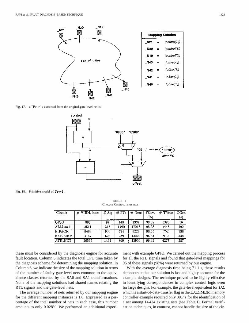
and are the RTL signals for whichwe apply our solution to the mapping problem (Section II). Themapping solution yields the region shown in Fig. 17,where is the gate-level net corresponding to ,and so on.
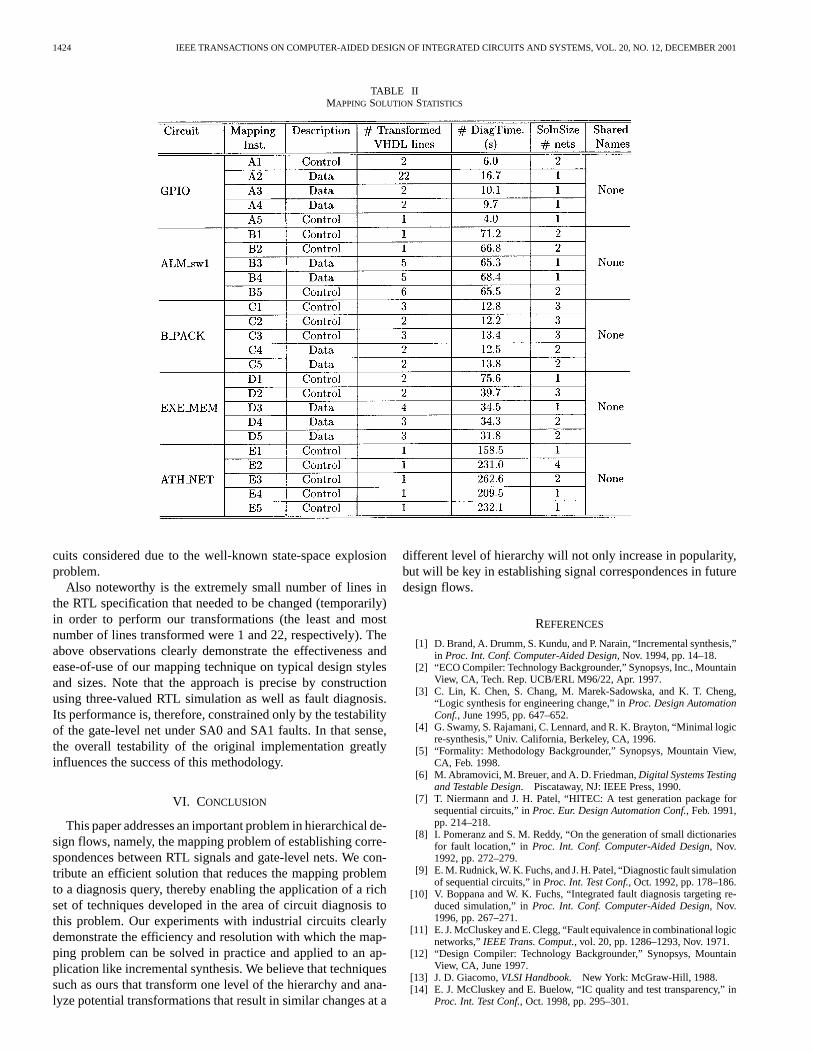
We are now ready to verify that the marked region in thegate-level netlist indeed corresponds to in the RTL de-scription. For this purpose, we generate the primitive model for
, , as shown in Fig. 18. This primitive modeland the extracted “sea_of_gates” from Fig. 17 form the inputs toour equivalence checking engine which results in “affirmative”verification.
We then apply the EC to the primitive model in Fig. 18. Inother words, we modify constant “0011” to “0010” in Fig. 18.A gate-level description is then synthesized from the modifiedprimitive model, which then replaces shown inFig. 17. This completes incremental synthesis.
V. EXPERIMENTAL RESULTS
The techniques described in this paper were evaluated withinthe framework of an inhouse synthesis flow with the help of
five example designs. The examples were chosen from a suiteof Fujitsu designs used in telecommunication and networkingapplications. A designer-specified set of mapping instances inthese examples were then selected for analysis. We applied thediagnosis-based solution methodology (Section III) to find thecorresponding gate-level nets. Once the mapping solutions weredetermined, we validated them using the equivalence checker[18].
Typical synthesis of a circuit in our set-up proceeds as fol-lows. At the top-level, the Synopsys Design Compiler [12] takesin the RTL specification of the circuit as its input along with thespecified constraints. High-effort synthesis is then used to opti-mize the design for the specified constraints. The output of De-sign Compiler is then customized and technology-mapped usingan industrial cell library to a gate-level netlist. Then, iterativeimprovement procedures are used at the logic level to enhancethe quality of the final gate-level netlist for area and/or delayconstraints. Most nontrivial name correspondences between theRTL signals and the gate-level nets except those of the design’sinputs and outputs are lost at this stage.
Table I describes the characteristics of the different bench-marks. Circuit GPIO is a general-purpose input–output con-troller that is used as an interface circuitry in system chips.
is an asynchronous transfer mode switch part whileis a memory controller. and
form portions of popularly used chip sets. Columns 2 and 3 in-dicate the size of the specifications and the number of signalsat the RTL. Columns 4 and 5 give postsynthesis gate-level sta-tistics in terms of the number of flip-flops and number of nets,respectively. Columns 6, 7, and 8 report the results of test gen-eration (fault coverage, number of test vectors, and test gener-ation time) obtained from running the gate-level sequential testgenerator HITEC [7] on the different circuits. Note that HITECgenerates test vectors only for fault detection and does not ex-plicitly target fault diagnosis. The central processing unit (CPU)time was measured on a 360-MHz UltraSparc 60 workstationwith 512-MB dynamic random access memory.
Our experiments to study the effectiveness of the diagnosis-based solution framework consisted of first selecting a designer-specified set of mapping instances for analysis and then ap-plying our diagnosis-based mapping solution. The results aresummarized in Table II. Columns 2 and 3 describe the mappinginstances and their classification into the functionality (Databitor Control bit) that they describe. For example, mapping in-stance is a parity control bit set in a nested conditional con-struct. Mapping instance is a data bit assigned values in acase construct. This example was specifically selected since adesign error in one of the assignments tomade it a suitablecandidate for the incremental synthesis procedure described inFig. 15. For any mapping instance, both SA0 and SA1 transfor-mations were applied to the RTL signal for generating the faultyresponses using HITEC-generated test vectors. Column 4 re-ports the number of VHDL lines affected by carrying out an SA0or SA1 transformation. A state-of-the-art fault diagnosis engine[19] was then used to determine the gate-level net (or nets) cor-responding to the RTL signal. This engine exploits three-valuedfault simulation to perform efficient fault diagnosis. This is im-portant because faulty responses can contain somevalues and
RAVI et al.: FAULT-DIAGNOSIS -BASED TECHNIQUE 1423
Fig. 17. G(Proc1) extracted from the original gate-level netlist.
Fig. 18. Primitive model ofProc1.
TABLE ICIRCUIT CHARACTERISTICS
these must be considered by the diagnosis engine for accuratefault location. Column 5 indicates the total CPU time taken bythe diagnosis scheme for determining the mapping solution. InColumn 6, we indicate the size of the mapping solution in termsof the number of faulty gate-level nets common to the equiv-alence classes returned by the SA0 and SA1 transformations.None of the mapping solutions had shared names relating theRTL signals and the gate-level nets.
The average number of nets returned by our mapping enginefor the different mapping instances is 1.8. Expressed as a per-centage of the total number of nets in each case, this numberamounts to only 0.028%. We performed an additional experi-
ment with example GPIO. We carried out the mapping processfor all the RTL signals and found that gate-level mappings for95 of these signals (98%) were returned by our engine.
With the average diagnosis time being 71.1 s, these resultsdemonstrate that our solution is fast and highly accurate for theexample designs. The technique proved to be highly effectivein identifying correspondences in complex control logic evenfor large designs. For example, the gate-level equivalent for,which is a start-of-data-transfer flag in the memorycontroller example required only 39.7 s for the identification ofa net among 14 424 existing nets (see Table I). Formal verifi-cation techniques, in contrast, cannot handle the size of the cir-
1424 IEEE TRANSACTIONS ON COMPUTER-AIDED DESIGN OF INTEGRATED CIRCUITS AND SYSTEMS, VOL. 20, NO. 12, DECEMBER 2001
TABLE IIMAPPING SOLUTION STATISTICS
cuits considered due to the well-known state-space explosionproblem.
Also noteworthy is the extremely small number of lines inthe RTL specification that needed to be changed (temporarily)in order to perform our transformations (the least and mostnumber of lines transformed were 1 and 22, respectively). Theabove observations clearly demonstrate the effectiveness andease-of-use of our mapping technique on typical design stylesand sizes. Note that the approach is precise by constructionusing three-valued RTL simulation as well as fault diagnosis.Its performance is, therefore, constrained only by the testabilityof the gate-level net under SA0 and SA1 faults. In that sense,the overall testability of the original implementation greatlyinfluences the success of this methodology.
VI. CONCLUSION
This paper addresses an important problem in hierarchical de-sign flows, namely, the mapping problem of establishing corre-spondences between RTL signals and gate-level nets. We con-tribute an efficient solution that reduces the mapping problemto a diagnosis query, thereby enabling the application of a richset of techniques developed in the area of circuit diagnosis tothis problem. Our experiments with industrial circuits clearlydemonstrate the efficiency and resolution with which the map-ping problem can be solved in practice and applied to an ap-plication like incremental synthesis. We believe that techniquessuch as ours that transform one level of the hierarchy and ana-lyze potential transformations that result in similar changes at a
different level of hierarchy will not only increase in popularity,but will be key in establishing signal correspondences in futuredesign flows.
REFERENCES
[1] D. Brand, A. Drumm, S. Kundu, and P. Narain, “Incremental synthesis,”in Proc. Int. Conf. Computer-Aided Design, Nov. 1994, pp. 14–18.
[2] “ECO Compiler: Technology Backgrounder,” Synopsys, Inc., MountainView, CA, Tech. Rep. UCB/ERL M96/22, Apr. 1997.
[3] C. Lin, K. Chen, S. Chang, M. Marek-Sadowska, and K. T. Cheng,“Logic synthesis for engineering change,” inProc. Design AutomationConf., June 1995, pp. 647–652.
[4] G. Swamy, S. Rajamani, C. Lennard, and R. K. Brayton, “Minimal logicre-synthesis,” Univ. California, Berkeley, CA, 1996.
[5] “Formality: Methodology Backgrounder,” Synopsys, Mountain View,CA, Feb. 1998.
[6] M. Abramovici, M. Breuer, and A. D. Friedman,Digital Systems Testingand Testable Design. Piscataway, NJ: IEEE Press, 1990.
[7] T. Niermann and J. H. Patel, “HITEC: A test generation package forsequential circuits,” inProc. Eur. Design Automation Conf., Feb. 1991,pp. 214–218.
[8] I. Pomeranz and S. M. Reddy, “On the generation of small dictionariesfor fault location,” in Proc. Int. Conf. Computer-Aided Design, Nov.1992, pp. 272–279.
[9] E. M. Rudnick, W. K. Fuchs, and J. H. Patel, “Diagnostic fault simulationof sequential circuits,” inProc. Int. Test Conf., Oct. 1992, pp. 178–186.
[10] V. Boppana and W. K. Fuchs, “Integrated fault diagnosis targeting re-duced simulation,” inProc. Int. Conf. Computer-Aided Design, Nov.1996, pp. 267–271.
[11] E. J. McCluskey and E. Clegg, “Fault equivalence in combinational logicnetworks,”IEEE Trans. Comput., vol. 20, pp. 1286–1293, Nov. 1971.
[12] “Design Compiler: Technology Backgrounder,” Synopsys, MountainView, CA, June 1997.
[13] J. D. Giacomo,VLSI Handbook. New York: McGraw-Hill, 1988.[14] E. J. McCluskey and E. Buelow, “IC quality and test transparency,” in
Proc. Int. Test Conf., Oct. 1998, pp. 295–301.
RAVI et al.: FAULT-DIAGNOSIS -BASED TECHNIQUE 1425
[15] I. Hartanto, V. Boppana, J. H. Patel, and W. K. Fuchs, “Diagnostic testpattern generation for sequential circuits,” inProc. VLSI Test Symp., Apr.1997, pp. 196–202.
[16] J. Mohnke, “A signature-based approach to formal logic verification,”Ph.D. dissertation, Univ. Halle, Halle, Germany, 1999.
[17] J. R. Burch and V. Singhal, “Robust latch mapping for combinationalequivalence checking,” inProc. Int. Conf. Computer-Aided Design, Nov.1998, pp. 563–569.
[18] ASSURE User Manual, Fujitsu Labs of America, Sunnyvale, CA, Dec.1998.
[19] V. Boppana, R. Mukherjee, J. Jain, M. Fujita, and P. Bollineni, “Multipleerror diagnosis based on X-lists,” inProc. Design Automation Conf.,June 1999, pp. 660–665.
Srivaths Ravi received the B.Tech. degree inelectrical engineering from the Indian Institute ofTechnology, Madras, India, in 1996 and the M.A.and Ph.D. degrees in electrical engineering fromPrinceton University, Princeton, NJ, in 1998 and2001, respectively.
He is currently a Research Staff Member withNEC Computer and Communications Laboratories,Princeton, NJ. His current research interests includetesting and synthesis of digital circuits.
Dr. Ravi received the Siemens Medal from the In-dian Institute of Technology in addition to various awards at the 1998 and 2000International Conference on VLSI Design.
Indradeep Ghosh(S’94–M’98) received the B.Tech. degree in computer sci-ence and engineering from the Indian Institute of Technology, Kharagpur, India,in 1993 and the M.A. and Ph.D. degrees in electrical engineering from PrincetonUniversity, Princeton, NJ, in 1995 and 1998, respectively.
He is currently a Member of Research Staff with the Advanced Computer-Aided Design Research Group, Fujitsu Laboratories of America, Sunnyvale,CA. He has authored or coauthored more than 20 technical papers in journalsand conferences. His current research interests include design for testability,high-level test generation, built-in self-test, high-level synthesis, and high-leveldesign verification and diagnosis.
Dr. Ghosh received the Honorable Mention Award at the International Con-ference on VLSI Design in 1998. He is the Audio–Visual Chair of the TutorialsGroup of the IEEE Computer Society Test Technology Technical Committee.
Vamsi Boppanareceived the B.Tech. (hons) degree in computer science andengineering from the Indian Institute of Technology, Kharagpur, India, in 1993and the M.S. and Ph.D. degrees in electrical and computer engineering from theUniversity of Illinois at Urbana-Champaign in 1995 and 1997, respectively.
He is a Cofounder and Principal Engineer of Zenasis Technologies, a VLSIdesign company creating leading-edge automated transistor-level optimizationtechnologies. He has authored or coauthored over 35 technical papers and hasfive patent-pending inventions. He has served on the program committee of theAsia South Pacific Design Automation Conference and as a Session Chair atseveral computer-aided design and test conferences, including the InternationalConference on Computer-Aided Design. His current research interests includeall aspects of VLSI design, test, and verification.
Dr. Boppana received the Indian Institute of Technology TCS Best ProjectAward in 1993, the University of Illinois Van Valkenburg Fellowship in 1995,the Best Paper Award at the VLSI Test Symposium in 1997, and a Fujitsu Lab-oratories of America Intellectual Property Contribution Award in 1999.
Niraj K. Jha (S’85–M’85–SM’93–F’98) receivedthe B.Tech. degree in electronics and electricalcommunication engineering from the Indian Instituteof Technology, Kharagpur, India, in 1981, the M.S.degree in electrical engineering from the StateUniversity of New York, Stony Brook, in 1982, andthe Ph.D. degree in electrical engineering from theUniversity of Illinois, Urbana, in 1985.
He is currently a Professor of Electrical Engi-neering with Princeton University, Princeton, NJ.He is also the Director of the Center for Embedded
System-on-a-Chip Design, funded by the New Jersey Commission in Scienceand Technology. He was the Program Chair of the 1992 Workshop onFault-Tolerant Parallel and Distributed Systems. He is currently the Editor ofthe Journal of Electronic Testing: Theory and Applications(JETTA) and hasserved as a Guest Editor for a JETTA Special Issue on High-Level Synthesis.He has authored or coauthored two books entitledTesting and Reliable Designof CMOS Circuits (Norwell, MA: Kluwer, 1990) andHigh-Level PowerAnalysis and Optimization(Norwell, MA: Kluwer, 1998) and more than 180technical papers. His current research interests include computer-aided designof integrated circuits, low-power design, digital system testing, and distributedcomputing.
Dr. Jha received the AT&T Foundation Award, the NEC Preceptorship Awardfor research excellence, and the Best Paper Award at the International Confer-ence on Computer Design in 1993, the Fault-Tolerant Computing Symposiumin 1997, the International Conference on VLSI Design in 1998, and the De-sign Automation Conference in 1999. He was an Associate Editor of the IEEETRANSACTIONS ONCIRCUITS AND SYSTEMS II: A NALOG AND DIGITAL SIGNAL
PROCESSINGand IEEE TRANSACTIONS ONVERY LARGE SCALE INTEGRATION
(VLSI) SYSTEMS.


![GCC internals intro y optimizationesnicolasw/Docencia/CP/gcc_int_intro.pdf · Optimizaciones Back-end Backend: – RTL tree + RTL language + RTL Engine + RTL Compiler [Middle-End]](https://img.pdfslide.us/doc/110x75/5f066be67e708231d417e97b/gcc-internals-intro-y-optimizationes-nicolaswdocenciacpgccintintropdf-optimizaciones.jpg)