Embed Size (px)
Citation preview
FAULK ALF TLC #114355
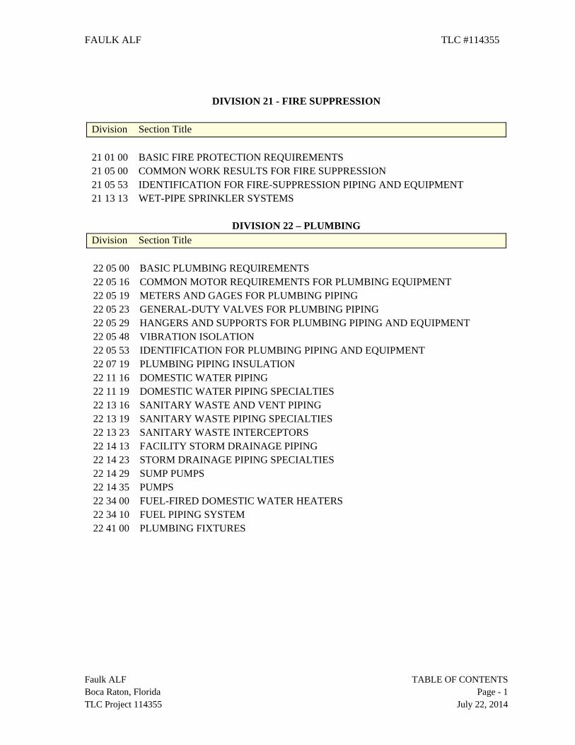
DIVISION 21 - FIRE SUPPRESSION
Division Section Title 21 01 00 BASIC FIRE PROTECTION REQUIREMENTS 21 05 00 COMMON WORK RESULTS FOR FIRE SUPPRESSION 21 05 53 IDENTIFICATION FOR FIRE-SUPPRESSION PIPING AND EQUIPMENT 21 13 13 WET-PIPE SPRINKLER SYSTEMS
DIVISION 22 – PLUMBING
Division Section Title
22 05 00 BASIC PLUMBING REQUIREMENTS 22 05 16 COMMON MOTOR REQUIREMENTS FOR PLUMBING EQUIPMENT 22 05 19 METERS AND GAGES FOR PLUMBING PIPING 22 05 23 GENERAL-DUTY VALVES FOR PLUMBING PIPING 22 05 29 HANGERS AND SUPPORTS FOR PLUMBING PIPING AND EQUIPMENT 22 05 48 VIBRATION ISOLATION 22 05 53 IDENTIFICATION FOR PLUMBING PIPING AND EQUIPMENT 22 07 19 PLUMBING PIPING INSULATION 22 11 16 DOMESTIC WATER PIPING 22 11 19 DOMESTIC WATER PIPING SPECIALTIES 22 13 16 SANITARY WASTE AND VENT PIPING 22 13 19 SANITARY WASTE PIPING SPECIALTIES 22 13 23 SANITARY WASTE INTERCEPTORS 22 14 13 FACILITY STORM DRAINAGE PIPING 22 14 23 STORM DRAINAGE PIPING SPECIALTIES 22 14 29 SUMP PUMPS 22 14 35 PUMPS 22 34 00 FUEL-FIRED DOMESTIC WATER HEATERS 22 34 10 FUEL PIPING SYSTEM 22 41 00 PLUMBING FIXTURES
Faulk ALF TABLE OF CONTENTS Boca Raton, Florida Page - 1 TLC Project 114355 July 22, 2014
FAULK ALF TLC #114355
Faulk ALF TABLE OF CONTENTS Boca Raton, Florida Page - 2 TLC Project 114355 July 22, 2014
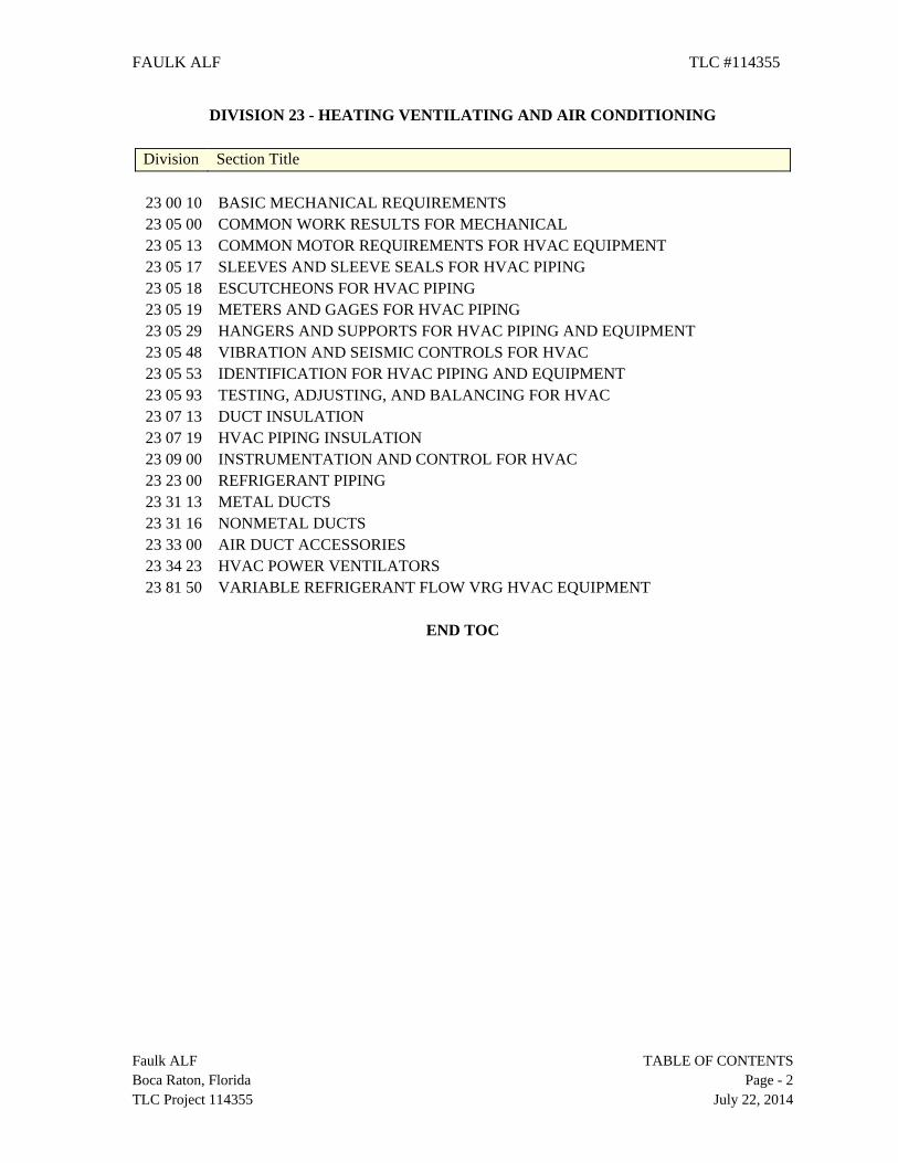
DIVISION 23 - HEATING VENTILATING AND AIR CONDITIONING
Division Section Title
23 00 10 BASIC MECHANICAL REQUIREMENTS 23 05 00 COMMON WORK RESULTS FOR MECHANICAL 23 05 13 COMMON MOTOR REQUIREMENTS FOR HVAC EQUIPMENT 23 05 17 SLEEVES AND SLEEVE SEALS FOR HVAC PIPING 23 05 18 ESCUTCHEONS FOR HVAC PIPING 23 05 19 METERS AND GAGES FOR HVAC PIPING 23 05 29 HANGERS AND SUPPORTS FOR HVAC PIPING AND EQUIPMENT 23 05 48 VIBRATION AND SEISMIC CONTROLS FOR HVAC 23 05 53 IDENTIFICATION FOR HVAC PIPING AND EQUIPMENT 23 05 93 TESTING, ADJUSTING, AND BALANCING FOR HVAC 23 07 13 DUCT INSULATION 23 07 19 HVAC PIPING INSULATION 23 09 00 INSTRUMENTATION AND CONTROL FOR HVAC 23 23 00 REFRIGERANT PIPING 23 31 13 METAL DUCTS 23 31 16 NONMETAL DUCTS 23 33 00 AIR DUCT ACCESSORIES 23 34 23 HVAC POWER VENTILATORS 23 81 50 VARIABLE REFRIGERANT FLOW VRG HVAC EQUIPMENT
END TOC
SECTION 21 01 00
BASIC FIRE PROTECTION REQUIREMENTS
Faulk ALF BASIC FIRE PROTECTION REQUIREMENTS Boca Raton, Florida 21 01 00 - 1 TLC Project 114355 July 22, 2014
PART 1 - GENERAL
1.01 RELATED DOCUMENTS
A. Basic Requirements: Requirements of the Contract Forms, Conditions of the Contract, Specifications, Drawings, and Addenda and Contract Modifications (the Contract Documents), apply to the requirements of each Section of Division 23.
B. Conflicts: Nothing contained in this Section shall be construed to conflict in any way
with other provisions or requirements of the Contract documents. The intent is that this Section will take precedence. Where differences arise, the Architect shall decide which directions or instructions take precedence.
1.02 SUMMARY
A. General: Unless an item is specifically mentioned as being provided by others, the requirements of Division 23 Contract Documents shall be completed. The systems, equipment, devices and accessories shall be installed, finished, tested and adjusted for continuous and proper operation. Any apparatus, material or device not shown on the Drawings but mentioned in these Specifications, or vice versa, or any incidental accessories necessary to make the project complete and operational in all respects, shall be furnished, delivered and installed without additional expense to the Owner. Include all materials, equipment, supervision, operation, methods and labor for the fabrication, installation, start-up and tests necessary for complete and properly functioning systems.
1.03 APPLICABLE STANDARDS
A. Code Compliance: Refer to Division 1. As a minimum, unless otherwise indicated, comply with all rules, regulations, standards, codes, ordinances and laws of local, state and federal governments and the amendments and interpretation of such rules, regulations, standards, codes, ordinances and laws of local, state and federal governments by the authorities having lawful jurisdiction.
B. ADA: Comply with the requirements of the Americans with Disabilities Act (ADA). C. Comply: With the National Fire Protection Association (NFPA) Standards and other
Codes and Standards as adopted by the Local Authority having Jurisdiction and as indicated.
D. Florida Building Code 2010: Conform in strict compliance to the Florida Building Code (FBC) and the amendments which are enforced by the local authority having jurisdiction. 1. Florida Building Code – Mechanical 2010 Edition 2. Florida Building Code – Plumbing 2010 Edition 3. Florida Building Code – Chapter 13 Florida Energy Efficiency for Building
Construction 2010 Edition
4. FGI - Guidelines for Design and Construction of Healthcare Facilities, 2010 Edition
E. Florida Administrative Code: 59A-3, Hospitals (current edition).
F. Florida Fire Marshall’s Rule Chapter 69A-3.012.
G. Florida Administrative Code Rule Chapter 69A-60.
H. NATIONAL FIRE PROTECTION (NFPA) Standards:
1. NFPA 1 – Uniform Fire Code, 2009 Edition 2. NFPA-10, Standard for Portable Fire Extinguishers, 2007 Edition 3. NFPA-13, Standard for the Installation of Sprinkler Systems, 2007 Edition 4. NFPA-14, Standard for the Installation of Standpipe and Hose Systems, 2007
Edition 5. NFPA-17, Standard for Dry-Chemical Extinguishing Systems, 2009 Edition 6. NFPA-20, Standard for the Installation of Stationary Pumps for Fire Protection,
2007 Edition 7. NFPA-24, Standards for the Installation of Private Fire Service Mains and Their
Appurtenances, 2007 Edition 8. NFPA-30, Flammable and Combustible Liquids Code, 2008 Edition 9. NFPA-54, National Fuel Gas Code, 2009 Edition
10. NFPA-70, National Electrical Code, 2008 Edition 11. NFPA-72, National Fire Alarm Code, 2007 Edition 12. NFPA-90A, Standard for the Installation of Air Conditioning and Ventilation
Systems, 2009 Edition 13. NFPA-90B, Standard for the Installation of Warm Air Heating and Air
Conditioning Systems, 2009 Edition 14. NFPA-99, Standard for Health Care Facilities, 2005 Edition 15. NFPA-101A, Guide to Alternative Approaches to Life Safety, 2007 Edition 16. NFPA-214, Water Cooling Towers, 2011 Edition 17. NFPA-704, Standard System for the Identification of the Fire Hazards of
Materials for Emergency Response, 2007 Edition 18. NFPA-780, Installation of Lightning Protection Systems, 2011 Edition 19. NFPA-1963, Standard for Fire Hose Connections, 2003 Edition 20. NFPA-2001, Standard on Clean Agent Fire Extinguishing Systems, 2008
Edition
I. Notification: Comply with all of the requirements of the Federal "Right-To-Know" Regulations and the Florida "Right-To-Know" Law and provide notification to all parties concerned as to the use of toxic substances.
1.04 DRAWINGS AND SPECIFICATIONS
A. Intent: The intent of the drawings and specifications is to establish minimum acceptable quality standards for materials, equipment and workmanship, and to provide operable mechanical systems complete in every respect.
Faulk ALF BASIC FIRE PROTECTION REQUIREMENTS Boca Raton, Florida 21 01 00 - 2 TLC Project 114355 July 22, 2014
B. Equipment Placement: The drawings are diagrammatic, intended to show general arrangement, capacity and location of various components, equipment and devices. Each location shall be determined by reference to the general building plans and by actual measurements in the building as built. Reasonable changes in locations ordered by the Architect prior to the performance of the affected Work shall be provided at no additional cost to the Owner.
C. Drawing Scale: Due to the small scale of the drawings, and to unforeseen job conditions, all required offsets, transitions and fittings may not be shown but shall be provided at no additional cost.
D. Conflict: In the event of a conflict, the Architect will render an interpretation in accordance with the General Conditions.
1.05 DEFINITIONS
A. Provide/Install: The word "provide" shall mean furnish, install, connect, test, complete, and leave ready for operation. The word "install" where used in conjunction with equipment furnished by the Owner or under another contract shall mean mount, connect, complete, and leave ready for operation.
B. Concealed: The surface of insulated or non-insulated piping, ductwork or equipment is concealed from view when standing inside a finished room, such as inside a chase or above a ceiling.
C. Exposed: The surface of insulated or non-insulated piping, ductwork or equipment is seen from inside a finished room, such as inside an equipment or air handling unit room.
D. Protected: The surface of insulated or non-insulated piping, ductwork or equipment on the exterior of the building but protected from direct exposure to rain by an overhang, eave, in an unconditioned parking garage or building crawl space.
E. Unprotected: The surface of insulated or non-insulated piping, ductwork or equipment on the exterior of the building and exposed to rain.
F. Abbreviations: Abbreviations, where not defined in the Contract Documents, shall be interpreted to mean the normal construction industry terminology, as determined by the Architect. Plural words shall be interpreted as singular and singular words shall be interpreted as plural where applicable for context of the Contract Documents.
1.06 SHOP DRAWINGS
A. General: Refer to paragraph entitled "SUBMITTAL" in this section. Include the following data:
1. Shop Drawings:
a. Submit shop drawings for the following: (1) Each Piping System (2) Coordination Drawings
Faulk ALF BASIC FIRE PROTECTION REQUIREMENTS Boca Raton, Florida 21 01 00 - 3 TLC Project 114355 July 22, 2014
1.07 RECORD DRAWINGS
A. Production: Maintain one set of black or blue line on white project record "as-built" drawings at the site. At all times the set shall be accurate, clear, and complete, indicating the actual installation. Record drawings shall be updated weekly to record the present stage of progress. These drawings shall be available to the Architect at all times. Equipment schedules, control diagrams, sequences of operation shall also be updated.
B. Completion: Prior to substantial completion, transfer onto an unmarked second set of drawings all changes, marked in colored pencil, and submit them to the Architect. Upon completion of all punch lists, transfer all "As-Built" conditions to the AutoCAD drawing files, package three (3) print sets of full size drawings and two (2) CDs of the AutoCAD drawing files with associated reference files and submit them to the Architect for review and approval.
1.08 SUBMITTAL
A. General: The provisions of this section are supplemental to the requirements in Division 1, and only apply to the material and equipment covered in Division 23.
B. Time: Submit manufacturer's literature, performance data and installation instructions covered in each Section of Division 23 under an individual letter of transmittal within 30 days after Notice to Proceed unless otherwise indicated.
C. Submitter's Review: All items required for each section shall be reviewed before submittal. Submittal information for each item shall bear a review stamp of approval, indicating the name of the Contractor and Subcontractor (where applicable), the material suppliers, the initials of submitter and date checked. Responsibility for errors or omissions in submittals shall not be relieved by the Architect's review of submittals. Responsibility for submittals cannot be subrogated to material suppliers by Contractors or Subcontractors.
1. Review of the submittal data, whether indicated with "APPROVED" or with
review comments, does not constitute authorization for or acceptance of a change in the contract price.
D. Architect's Review: The submittal data shall be reviewed only for general conformance with the design concept of the project and for general compliance with the Contract Documents. Any action indicated is subject to the requirements of the Contract Documents. Reviews of submittal data review shall not include quantities; dimensions (which shall be confirmed and correlated at the job site); fabrication processes; techniques of construction; and co-ordination of the submittal data with all other trades. Copies of the submittal data will be returned marked "ACCEPTED AS SUBMITTED", "ACCEPTED AS NOTED", "REVISED AS NOTED AND RESUBMIT", "REJECTED, REVISED AS NOTED AND RESUBMIT”.
E. Submittal Items: Submittal items shall be inserted in a Technical Information Brochure. Mark the appropriate specification section or drawing reference number in the right hand corner of each item. All typewritten pages shall be on the product or equipment manufacturer's printed letterhead.
Faulk ALF BASIC FIRE PROTECTION REQUIREMENTS Boca Raton, Florida 21 01 00 - 4 TLC Project 114355 July 22, 2014
1. Manufacturer's Literature: Where indicated, include the manufacturer's printed
literature. Literature shall be clearly marked to indicate the item intended for use.
2. Performance Data: Provide performance data, wiring and control diagrams and scale drawings which show that proposed equipment will fit into allotted space (indicate areas required for service access, connections, etc.), and other data required for the Architect to determine that the equipment complies with the Contract Documents. Where noted, performance data shall be certified by the manufacturer at the design rating points.
3. Installation Instructions: Where requested, each product submittal shall include
the manufacturer's installation instructions. Generic installation instructions are not acceptable. Instructions shall be the same as those included with the product when it is shipped from the factory.
4. Written Operating Instructions: Instructions shall be the manufacturer's written operating instructions for the specified product. If the instructions cover more than one model or type of product they shall be clearly marked to identify the instructions that cover the product delivered to the project. Operating Instructions shall be submitted immediately after the product or equipment submittal has been returned from the Architect marked "APPROVED" or "APPROVED AS NOTED".
5. Maintenance Instructions: Information shall be the manufacturer's printed instructions and parts lists for the equipment furnished. If the instructions cover more than one model or type of equipment they shall be marked to identify the instructions for the furnished product. Submit maintenance instructions immediately after the product or equipment submittal has been returned from the Architect marked "APPROVED" or "APPROVED AS NOTED".
F. Substitutions:
1. General: Refer to Division 1. Substitutions may be considered for any product or equipment of a manufacturer. See paragraph entitled "MANUFACTURER" in this Section. Any product or equipment may be submitted for review; however, only one substitution per item will be considered. If a substituted product or equipment item is rejected, provide the specified product or equipment.
a. Submittal shall include the name of the material or equipment to be
substituted, equipment model numbers, drawings, catalog cuts, performance and test data and any other data or information necessary for the Architect to determine that the equipment meets the specification requirements. If the Architect accepts any proposed substitutions, such acceptance will be set forth in writing.
Faulk ALF BASIC FIRE PROTECTION REQUIREMENTS Boca Raton, Florida 21 01 00 - 5 TLC Project 114355 July 22, 2014
b. Substituted equipment with all accessories installed or optional equipment where permitted and found acceptable, must conform to space requirements. Substituted equipment that cannot meet space requirements, whether accepted or not, shall be replaced at no additional expense to the Owner. If the substituted item affects the work of other trades, the Request for Substitution form shall include a list of the necessary modifications.
2. Deviations: The Request for Substitution form shall include a complete list of
deviations from the scheduled item stating both the features and functions of the scheduled item and the comparable features and functions of the proposed substitution.
a. Any deviation not indicated in writing will be assumed to be identical to
the specified item even if it is shown otherwise on the submittal data. b. If a deviation not listed is found anytime after review and acceptance by
the Architect and that deviation, in the opinion of the Architect, renders the substituted item as unacceptable, the item shall be removed and replaced by the scheduled item at no additional cost to the Owner.
c. The Architect shall retain the right to specify modifications to the substituted item, correcting or adjusting for the deviation, if the Architect deems it to be in the best interest of the Owner.
3. Scheduled Item: A scheduled item is a product or item of equipment indicated in
the Contract Documents by manufacturer's name and model number identifying a single item. The manufacturer's trade name for a group of products that does not signify a single item including type, style, quality, performance, and sound rating shall not be classified as a scheduled item. Where more than one manufacturer and product model number are indicated, each shall be considered as a scheduled item.
4. Form: When a product or item of equipment is proposed as a substitution a
"REQUEST FOR SUBSTITUTION" form shall be completed and submitted with the required data. A copy of the form is included after the end of this section.
5. Rejection: Substituted products or equipment will be rejected if, in the opinion
of the Architect, the submittal does not meet any one of the following conditions or requirements:
a. The submittal data is insufficient or not clearly identified. The Architect
may or may not request additional information. b. The product or equipment will not fit the space available and still provide
the manufacturers published service area requirements. c. The product or equipment submitted is not equivalent to or better than the
specified item. Products or equipment of lesser quality may be considered provided an equitable financial rebate, satisfactory to the Architect, is to be returned to the Owner.
d. The product or equipment submitted has less capacity, efficiency and safety provisions than the specified item.
Faulk ALF BASIC FIRE PROTECTION REQUIREMENTS Boca Raton, Florida 21 01 00 - 6 TLC Project 114355 July 22, 2014
e. The product or equipment submitted does not have warranty, service and factory representation equivalent to that specified.
f. The Owner prefers not to accept the submitted product.
G. Technical Information Brochure:
1. Binder: Include binders with the first submittal for the Technical Information Brochure. Each binder shall be size 3 inch, hardcover, 3-ring type for 8-1/2" X 11" sheets. Provide correct designation on outside cover and on spine of each binder, i.e., MECHANICAL SUBMITTAL DATA, MECHANICAL OPERATION INSTRUCTION and MECHANICAL MAINTENANCE INSTRUCTIONS.
2. Number: Submit not less than five sets of binders for each of the three mechanical brochures indicated above. Each set shall consist of a minimum of two binders for submittal data and 1 binder each for operating instructions and for maintenance instructions. Additional binders shall be submitted at the request of the Architect. One set of binders shall be retained by the Architect. Three sets of binders shall be maintained for the Owner and the remaining set shall become the property of the Engineer.
3. Index: First sheet in each brochure shall be a photocopy of the "Division 23 Index" of the specifications. Second sheet shall list the firm name, address, phone number, superintendent's name for the contractor and all major subcontractors and suppliers associated with the project.
4. Dividers: Provide reinforced separation sheets tabbed with the appropriate specifications Section reference number for each Section in which submittal data or operation and maintenance instructions is required.
5. Specifications: Insert a copy of the specifications for each Section and all addenda applicable to the Section between each of the Section dividers.
1.09 SHOP DRAWINGS FOR PIPING SYSTEMS
A. Requirements: Make Shop Drawings for piping systems at a minimum scale of 1/4 inch per foot in AutoCAD Version 2013 and print on reproducible transparencies to verify clearances and equipment locations. Show required maintenance and operational clearances. Identify Shop Drawings by project name and include names of Architect, Engineer, Contractors, Subcontractors and supplier, date in Shop Drawing title block. Number drawings sequentially and indicate: 1. Architectural and structural backgrounds with room names and numbers, etc.,
including but not limited to plans, sections, elevations, details, etc. 2. Fabrication and erection dimensions. 3. Arrangements and sectional views. 4. Necessary details, including complete information for making connections to
equipment. 5. Descriptive names of equipment. 6. Modifications and options to standard equipment required by Contract
Documents.
Faulk ALF BASIC FIRE PROTECTION REQUIREMENTS Boca Raton, Florida 21 01 00 - 7 TLC Project 114355 July 22, 2014
B. Stamp Area: Leave 4 inch by 2-1/2 inch blank area near title block for Architect's shop drawing stamp. The acceptance of a shop drawing by indicating "APPROVED" does not relieve the contractor from full compliance with the sizes and equipment connections shown on the contract documents unless the changes are specifically indicated on the shop drawing.
C. Reference Key: Indicate by cross-reference the Contract Drawings, notes, or
Specification paragraph numbers where item(s) occur in the Contract Documents.
D. Additional Requirements: See specific Sections for additional requirements. 1.10 COORDINATION DRAWINGS
A. General: Provide detailed (minimum 1/4 inch per foot) scaled coordination drawings showing locations and positions of all architectural, structural, (FF&E) equipment, electrical, plumbing, fire protection and mechanical elements for all installations. Provide overlay drawings, prior to beginning work, indicating work in and above ceilings and in mechanical and electrical rooms with horizontal and vertical dimensions, to avoid interference with structural framing, ceilings, partitions and other services. Accommodate phasing and temporary conditions indicated on the contract drawings as necessary to complete the work without disruption to the Owner's use of the existing occupied areas of the building(s).
B. Coordination of Space: Coordinate use of project space and sequence of installation of mechanical and electrical work which is indicated diagrammatically on drawings. Follow routings shown for pipes, ducts and conduits as closely as practicable, with due allowance for available physical space; make runs parallel with lines of building. Utilize space efficiently to maximize accessibility for other installations, for maintenance, and for repairs.
C. In finished areas except as otherwise shown, conceal pipes, ducts, and wiring in construction. Coordinate locations of fixtures and outlets with finish elements. Contractor shall provide background drawings showing partitions, ceiling heights, and structural framing locations and elevations, and existing obstructions. Contractor shall resolve major interferences at initial coordination meeting prior to production of coordination drawings.
D. Precedence of Services: In event of conflicts and interferences involving location and layout of work, use the following priority to resolve interferences: 1. Structure has highest priority. 2. Walls systems. 3. Ceiling grid/light fixtures. 4. Gravity drainage lines. 5. Large pipe mains. 6. Ductwork/diffusers, registers and grilles. 7. Sprinkler heads. 8. Small piping and tubing/electrical conduit. 9. Access panels.
Faulk ALF BASIC FIRE PROTECTION REQUIREMENTS Boca Raton, Florida 21 01 00 - 8 TLC Project 114355 July 22, 2014
E. Drawings shall be developed on AutoCAD Version 2013 and utilize AIA Standard layering conventions. At the completion of the project construction, the Contractor shall provide two (2) full-sized print sets and two (2) CDs of all drawing files with related reference files representing as-built installations for Architect review. Upon approval that the submitted information is complete, a similar submittal shall be provided to the Owner.
F. Reference Key: Indicate by cross-reference the Contract Drawings, notes, or Specification paragraph numbers where item(s) occur in the Contract Documents.
G. Additional Requirements: See specific Sections for additional requirements. 1.11 MANUFACTURER'S CHECKOUT
A. Start-up and Checkout: At completion of installation and prior to performance verification, a factory-trained representative of the manufacturer shall provide start-up and checkout service. After the performance verification the manufacturer's representative shall examine performance information and check the equipment in operation, and sign "Check-Out Memo" for the record. Submit a copy of Memo on each item of equipment where indicated in individual sections of these specifications for inclusion in each Technical Information Brochure. The "Check-Out Memo" shall be included with the performance verification data. Do not request "Instruction in Operation Conference" or request final inspection until Memos have been submitted and found acceptable.
1.12 INSTRUCTION TO OWNER
A. General: Instructions to the Owner shall be by competent representatives of the manufacturers involved, with time allowed for complete coverage of all operating procedures. Provide classroom instruction and field training in the design, operation and maintenance of the equipment and troubleshooting procedures. Explain the identification system, operational diagrams, emergency and alarm provisions, sequencing requirements, seasonal provisions, security, safety, efficiency and similar provisions of the systems. On the date of substantial completion, turn over the prime responsibility for operation of the mechanical equipment and systems to the Owner's operating personnel.
B. Training Period: Unless otherwise indicated training periods shall encompass the following number of hours of classroom and hands-on instructions with a maximum period of 4 hours per day for either. Mixing classroom instructions and hands on training in the same day is unacceptable.
1. Training Periods:
a. 8 hours Classroom b. 4 hours Hands-on
C. Scheduling: Submit any remaining required items for checking at least one week before final inspection of building. When submittal items are found acceptable, notify Owner, in writing that an "Instruction in Operation Conference" may precede. Conference will be scheduled by the Owner. After the conference, copies of a memo certifying that the "Instruction in Operation Conference" and "Completed
Faulk ALF BASIC FIRE PROTECTION REQUIREMENTS Boca Raton, Florida 21 01 00 - 9 TLC Project 114355 July 22, 2014
Demonstration" have been made will be signed by Owner and the instructors, and one copy will be inserted in each Technical Information Brochure.
1.13 ALLOWANCES
A. General: Division 1. 1.14 ALTERNATES
A. Refer to Division 1. 1.15 STRUCTURAL CALCULATIONS FOR ROOF-MOUNTED EQUIPMENT
A. All roof-mounted devices, equipment and systems shall be constructed, designed and fastened to withstand wind loads of velocities up to 155 mph. Structural calculations for roof-mounted equipment shall be completed in accordance with Florida Building Code requirements and submitted by a structural engineer registered in the State of Florida.
PART 2 - PRODUCTS
2.01 MANUFACTURERS
A. Specified Products: Manufacturer’s names and product model numbers indicated on the drawings and in these specifications establish the type, style, quality, performance, and sound rating of the desired product. Listing of other manufacturers indicates that their equivalent products would be acceptable if they meet the specification requirements, the specific use and installation shown on the drawings, including space and clearance requirements, and the energy consumption and efficiency of the specified product. The listing of additional manufacturers in no way indicates that the manufacturer can provide an acceptable product.
B. Space Requirements: All manufactured products furnished on this project must have the required space and service areas indicated in the manufacturer's printed literature or shown on their shop drawing. When the manufacturer does not indicate the space required for servicing the equipment, the space shown on the drawings or as required by the Architect must be provided.
2.02 MATERIAL AND EQUIPMENT
A. General: Material and equipment used shall be produced by manufacturers regularly engaged in the production of similar items, and with a history of satisfactory use as judged by the Architect.
B. Specified Equipment: Equipment shall be the capacity and types indicated or shall be equivalent in the opinion of the Architect. Material and equipment furnished and installed shall be new, recently manufactured, of standard first grade quality and designed for the specific purpose. Equipment and material furnished shall be the manufacturer's standard item of production unless specified or required to be modified to suit job conditions. Sizes, material, finish, dimensions and the capacities for the specified application shall be published in catalogs for national distribution.
Faulk ALF BASIC FIRE PROTECTION REQUIREMENTS Boca Raton, Florida 21 01 00 - 10 TLC Project 114355 July 22, 2014
C. Compatibility: Material and equipment of one and the same kind, type or
classification and used for identical or similar purposes shall be made by the same manufacturer. Where more than one choice is available, select the options which are compatible with other products already selected. Compatibility is a basic general requirement of product selection.
D. Coordination of Materials: In the event of multiple award packages for the
completion of this work, the Contractor shall direct and lead the coordination effort necessary to ensure that all materials and equipment that have moving parts, are procured from the same manufacturer and are the same model as consistent with its use and as required by these specifications.
1. The Contractor shall additionally ensure that the installation of this material and
equipment is consistent for the Owner’s use and maintenance, and shall effect necessary adjustments to render the installations consistent.
2. In the event of dispute, the earlier award package materials, as prescribed by approved submittal documents, shall take precedent in defining the material and equipment coordination requirements of the project.
PART 3 - EXECUTION
3.01 WORKMANSHIP
A. General: The installation of materials and equipment shall be done in a neat, workmanlike and timely manner by an adequate number of craftsmen knowledgeable of the requirements of the Contract Documents. They shall be skilled in the methods and craftsmanship needed to produce a first-quality installation. Personnel who install materials and equipment shall be qualified by training and experience to perform their assigned tasks. All materials and equipment shall be installed per the manufacturer’s written requirements.
B. Acceptable Workmanship: Acceptable workmanship is characterized by first-quality appearance and function which conforms to applicable standards of building system construction and exhibits a degree of quality and proficiency which is judged by the Architect equivalent as or better than that ordinarily produced by qualified industry tradesmen.
C. Performance: Personnel shall not be used in the performance of the installation of material and equipment that, in the opinion of the Architect, are deemed to be careless or unqualified to perform the assigned tasks. Material and equipment installations not in compliance with the Contract Documents, or installed with substandard workmanship in the opinion of the Architect, shall be removed and reinstalled by qualified craftsmen at no change in the contract price.
3.02 CLEANING AND PROTECTION
A. General: Refer to Division 1. Faulk ALF BASIC FIRE PROTECTION REQUIREMENTS Boca Raton, Florida 21 01 00 - 11 TLC Project 114355 July 22, 2014
B. Emergency Contacts: Prior to the beginning of the project, provide the Owner with a
list of names, emergency telephone and beeper numbers of individuals who can be contacted during working and non-working hours, including weekends, for assistance throughout the warranty period if leaks, equipment failure or other damages occur. Update the list throughout installation and warranty to provide continuous availability of responsible parties to the Owner. If the Owner cannot contact the responsible party during an emergency situation, the Owner may affect emergency repairs through other means and may backcharge for the costs of repair material and labor incurred.
C. Emergency Contacts: Along with the operating and maintenance manual submittal,
provide the Owner with a list of the names and emergency telephone and beeper numbers of individuals who can be contacted during working and non-working hours, including weekends, for assistance throughout the warranty period should leaks, equipment failure or other damage occur. Update the list throughout warranty to provide continuous availability of responsible parties to the Owner. If the Owner cannot contact the responsible party during an emergency situation, the Owner may affect emergency repairs through other means and may backcharge for the costs of repair material and labor incurred.
D. Housekeeping: Keep interiors of duct and pipe systems clean and free from dirt,
rubbish and foreign matter. Close open ends of piping and ductwork at all times throughout the installation. Install 30% efficient filter media over each return air grille and open return duct opening; change media regularly during construction when dirty to keep duct interiors clean. Prevent dust, debris and foreign material from entering the piping and ductwork.
E. Equipment Protection: Protect fan motors, switches, equipment, fixtures, and other
items from dirt, rubbish and foreign matter. Do not operate air-handling equipment if the building is not clean or if dust can enter the coils or the fan housings.
F. Equipment Cleaning: Thoroughly clean equipment and entire piping systems
internally upon completion of installation and immediately prior to final acceptance. Open dirt pockets and strainers, blow down each piping system and clean strainer screens of accumulated debris. Remove accumulated dirt, scale, oil and foreign substances. Thoroughly wipe clean internal surfaces of ductwork and air handling units prior to request for substantial completion. (See para. 3.2 above.)
G. Building Cleanup: Remove debris, rubbish, leftover materials, tools and equipment
from work areas and site. Clean tunnels and closed off spaces of packing boxes, wood frame members and other waste materials used in the installation. Final acceptance shall not be approved until site is cleaned.
H. Fixture Cleanup: Remove temporary labels, stickers, etc., from fixtures and equipment. Do not remove permanent nameplates, equipment model numbers, ratings, etc.
I. Filter Replacement: Provide filters, with the same efficiency rating as required for the
final installation, for the protection of the air moving equipment and ductwork
Faulk ALF BASIC FIRE PROTECTION REQUIREMENTS Boca Raton, Florida 21 01 00 - 12 TLC Project 114355 July 22, 2014
continuously throughout the construction phase. Provide a new set of clean filters for the test and balance of the air side equipment.
J. Protection of Finished Installation: Where installation is required in areas previously
finished by other trades, protect the area from marring, soiling or other damage.
K. Air Handling Unit Operation During Construction Phase: Do not operate air handling equipment during building construction phase unless filter fabric is fastened to all duct systems’ inlets and all specified and scheduled air filters are installed to minimize dirt entry into ductwork and air moving equipment. When running air handling units to dry out the building, control the building temperature to drop very slowly, and verify all HVAC insulation is completed and doors and windows are installed and closed, to prevent condensation of water from humid air on building interior surfaces, equipment, materials and ductwork.
3.03 CORRECTION OF WORK
A. General: At no additional cost to the Owner, rectify discrepancies between the actual installation and contract documents when in the opinion of the T&B Agency or the Architect the discrepancies will affect system balance and performance.
B. Drive Changes: Include the cost of all pulley, belt, and drive changes, as well as balancing dampers, valves and fittings, and access panels to achieve proper system balance recommended by the T&B Agency.
3.04 COORDINATION AND ASSISTANCE
A. General: Provide all labor, equipment, tools and material required to operate the equipment and systems necessary for the acceptable testing of the systems and for the adjustment, calibration or repair of all electric or pneumatic automated control devices and components. These services shall be available on each working day during the period of final testing and balancing.
B. Drawings and Specifications: Provide to the Authority having Jurisdiction a complete set of project record drawings and specifications and an approved copy of all approved shop drawings and equipment submittals. The Authority having Jurisdiction shall be informed of all changes made to the system during construction, including applicable change orders.
C. Coordination: Coordinate the work of all trades and equipment suppliers to complete the modifications recommended by the Authority having Jurisdiction and accepted by the Architect. Cut or drill holes for the insertion of measuring devices as directed for test purposes; repair to as-new condition, inserting caps or covers to prevent leakage.
3.05 PREPARATIONS FOR PERFORMANCE VERIFICATION
A. Verification: Prior to commencement of the balancing by the T&B Agency, the Contractor shall verify in writing:
1. That strainers have been removed, cleaned and replaced, and that temporary
construction strainers have been removed. Faulk ALF BASIC FIRE PROTECTION REQUIREMENTS Boca Raton, Florida 21 01 00 - 13 TLC Project 114355 July 22, 2014
2. That air vents at high points of the piping systems have been inspected and
installed and operating freely.
3. That automatic valves, hand valves, and balancing valves have been placed in a fixed open position for full flow through all devices.
4. That linkages between valves and their actuators are secure, non-overloading
and non-binding.
5. That pressures for hydronic reducing valves have been set.
6. That pumps are operating at the correct rotation and specified horsepower.
7. That piping has been pressure tested and accepted and piping systems have been cleaned, flushed, sterilized and refilled with chemicals and prescribed treated water and vented.
8. That operating temperatures and pressures have been set for pressure regulating
valves, etc.
9. That the operating safeties (thermal overloads, firestat/freezestats, smoke detectors, relief valves, etc.), are installed and fully functional.
10. That equipment has been lubricated and can be operated without damage.
11. That the systems are operational and complete.
12. That no latent residual work remains to be completed. 3.06 ACCEPTANCE TESTING PROCEDURE
A. General: Each fire protection system shall be tested to confirm proper operation and function in accordance with the construction documents and sequence of operations.
B. The enclosed checklists shall be completed for each system and signed off by the fire protection sub-contractor project representative, then verified and signed-off by the construction manager systems engineer. All checklists shall be incorporated into the project's close-out manuals submitted for Owner record.
C. On-site testing by the Architect and Engineer shall be performed at the discretion of the Architect/Engineer for any or all systems to confirm test results and system function.
D. The Contractor is responsible to provide adequate time in the completion of the construction to perform these system tests prior to the AHCA final inspections in the affected areas/systems.
Faulk ALF BASIC FIRE PROTECTION REQUIREMENTS Boca Raton, Florida 21 01 00 - 14 TLC Project 114355 July 22, 2014
E. The Contractor is responsible for ensuring all required system tests are conducted successfully and recording associated test data and results, in accordance with NFPA 13 and NFPA 20.
F. The Contractor is responsible for contacting the Authority having Jurisdiction,
Architect and Engineer at least two weeks prior to system test availability and schedule acceptable to Architect/Engineer for on-site testing.
G. If, in the Architect's and Engineer's opinion, the test results indicate that the systems' installation is not adequately complete for testing, the testing shall be re-scheduled and the Contractor shall be responsible to prepare for such re-test.
H. Prior to Owner occupancy, all system testing shall be completed and approved.
3.07 PROTECTION OF MATERIALS AND EQUIPMENT
A. Replacement of Damaged Stored Material and Equipment: Any material and equipment that has been wet or otherwise damaged prior to installation, in the opinion of the Architect, shall be replaced with new material regardless of the condition of the material and equipment at the time of installation.
B. Repair of Damaged Installed Material and Equipment: After installation correct or repair dents, scratches and other visible blemishes. At the direction of Architect replace or repair to "as new" condition equipment which has been damaged during construction.
C. During construction, all piping system openings shall be capped with at least two layers of polyethylene film, fastened tightly in place with banding material or foil tape until connection of the continuation of such piping or ductwork is occurring.
D. All air diffusers serving critical care areas shall be disinfected per owner infection control guidelines with a commercial germicide complying with EPA regulations utilizing per manufacturer use standards prior to building occupancy.
3.08 COORDINATION OF SERVICES
A. General: Where phasing of the work requires partial occupancy, coordinate interruption of services to Owner-occupied areas in writing in advance with the Architect. Shutdown time and duration of services interruption shall be decided by the Owner. Provide shutoff valves at points of interconnection to minimize downtime. Procedures incidental to the outage shall be prepared in advance to minimize downtime.
B. General: Coordinate interruption of services in writing at least 1 week in advance
with the Architect. Shutdown time and duration of services interruption shall be decided by the Owner. Provide shutoff valves at points of interconnection to minimize downtime. Procedures incidental to the outage shall be prepared in advance to minimize downtime.
C. Protection of Facilities: Portions of the building may be operational during construction. Maintain operation of the equipment and systems whenever the installation interfaces with equipment or systems. Provide protection for the building, its contents and occupants wherever installation under the contract is performed. As necessary, move, store, and protect furniture, office fixtures and
Faulk ALF BASIC FIRE PROTECTION REQUIREMENTS Boca Raton, Florida 21 01 00 - 15 TLC Project 114355 July 22, 2014
carpets. Access to the building, including exit stairs, doors and passageways, and loading dock and other delivery areas shall be kept open and continuously accessible to the occupants. Workmen shall be confined to those areas directly involved in the project installation, and only during time periods indicated and approved by the Owner.
3.11 PAINTING OF MECHANICAL PIPING A. Apply paints according to manufacturer’s written instructions and to
recommendations in “MPI Manual”. Comply with Section 09123. 1. Use applicators and techniques suited for paint and substrate indicated. 2. Paint surfaces behind movable equipment and furniture same as similar
exposed surfaces. Before final installation, paint surfaces behind permanently fixed equipment or furniture with prime coat only.
3. Paint front and backsides of access panels, removable or hinged covers, and similar hinged items to match exposed surfaces.
4. Do not paint over labels of independent testing agencies or equipment name, identification, performance rating or nomenclature plates.
5. Primers specified in painting schedules may be omitted on items that are factory primed or factory finished if acceptable to topcoat manufacturers.
B. Tint each undercoat a lighter shade to facilitate identification of each coat if multiple
costs of same material are to be applied. Tint undercoats to match color of topcoat, but provide sufficient difference in shade of undercoats to distinguish each separate coat.
C. If undercoats or other conditions show through topcoat, apply additional costs until
cured file has a uniform paint finish, color, and appearance.
D. Apply paints to produce surface films without cloudiness, spotting, holidays, laps, brush marks, roller tracking, runs, sags, ropiness or other surface imperfections. Cut in sharp lines and color breaks.
E. Painting Fire Protection work:
1. Paint the following work where exposed in Equipment Rooms: a. Uninsulated metal piping. 2. Paint the following work where exposed in Occupied Spaces:
• Uninsulated metal piping. • Pipe hangers and supports.
3.12 FIELD QUALITY CONTROL
A. Dry Film Thickness Testing: Owner may engage the services of a qualified testing and inspecting agency to inspect and test paint for dry film thickness.
Faulk ALF BASIC FIRE PROTECTION REQUIREMENTS Boca Raton, Florida 21 01 00 - 16 TLC Project 114355 July 22, 2014
B. Contractor shall touch up and restore painted surfaces damaged by testing.
C. If test results show that dry film thickness of applied paint does not comply with
paint manufacturer’s written recommendations, Contractor shall pay for testing and apply additional coats as needed to provide dry film thickness that complies with paint manufacturer’s written recommendations.
3.13 CLEANING AND PROTECTION
A. At end of each workday, remove rubbish, empty cans, rags, and other discarded materials from Project site.
B. After completing paint application, clean spattered surfaces. Remove spattered paints
by washing, scraping, or other methods. Do not scratch or damage adjacent finished surfaces.
C. Protect work of other trades against damage from paint application. Correct damage
to work of other trades by cleaning, repairing, replacing, and refinishing, as approved by Architect, and leave in an undamaged condition.
D. At completion of construction activities of other trades, touch up and restore
damaged or defaced painted surfaces.
END OF SECTION 21 01 00
Faulk ALF BASIC FIRE PROTECTION REQUIREMENTS Boca Raton, Florida 21 01 00 - 17 TLC Project 114355 July 22, 2014
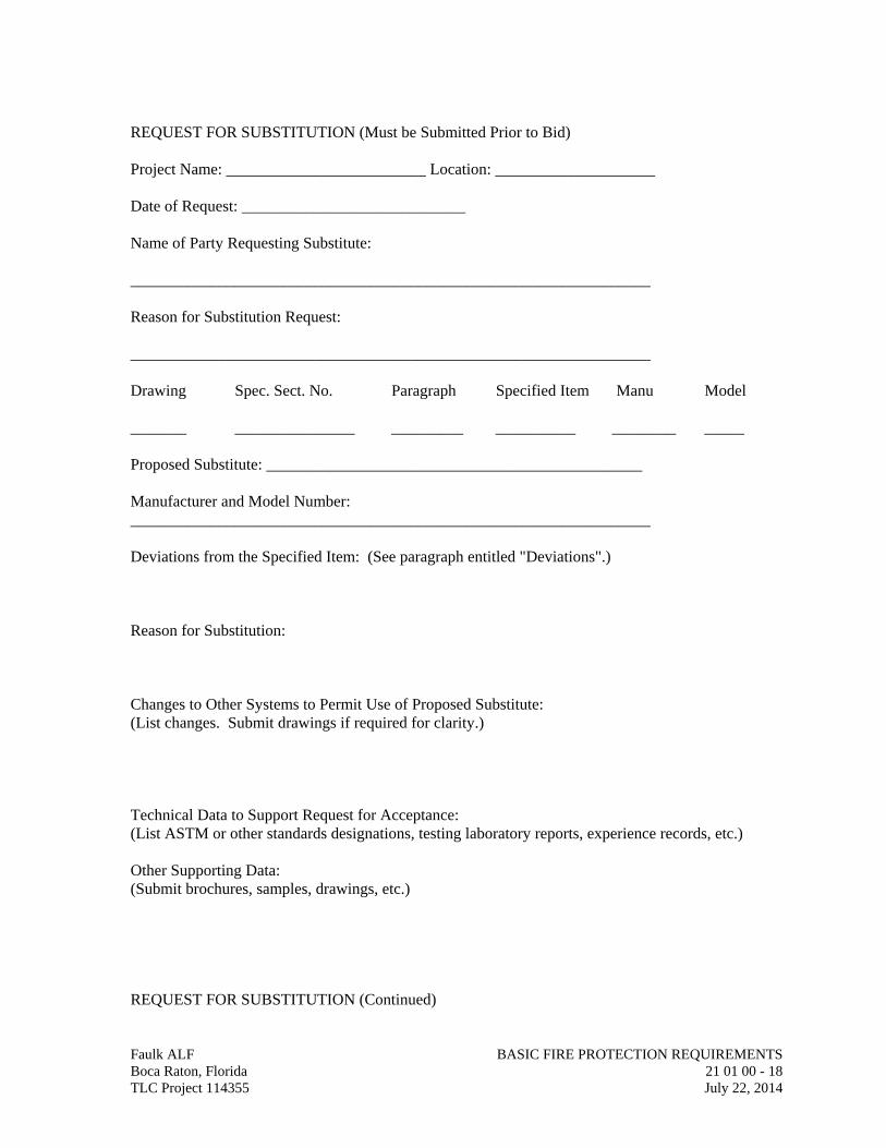
REQUEST FOR SUBSTITUTION (Must be Submitted Prior to Bid) Project Name: _________________________ Location: ____________________ Date of Request: ____________________________ Name of Party Requesting Substitute: _________________________________________________________________ Reason for Substitution Request: _________________________________________________________________ Drawing Spec. Sect. No. Paragraph Specified Item Manu Model _______ _______________ _________ __________ ________ _____ Proposed Substitute: _______________________________________________ Manufacturer and Model Number: _________________________________________________________________ Deviations from the Specified Item: (See paragraph entitled "Deviations".) Reason for Substitution: Changes to Other Systems to Permit Use of Proposed Substitute: (List changes. Submit drawings if required for clarity.) Technical Data to Support Request for Acceptance: (List ASTM or other standards designations, testing laboratory reports, experience records, etc.) Other Supporting Data: (Submit brochures, samples, drawings, etc.) REQUEST FOR SUBSTITUTION (Continued)
Faulk ALF BASIC FIRE PROTECTION REQUIREMENTS Boca Raton, Florida 21 01 00 - 18 TLC Project 114355 July 22, 2014
Faulk ALF BASIC FIRE PROTECTION REQUIREMENTS Boca Raton, Florida 21 01 00 - 19 TLC Project 114355 July 22, 2014
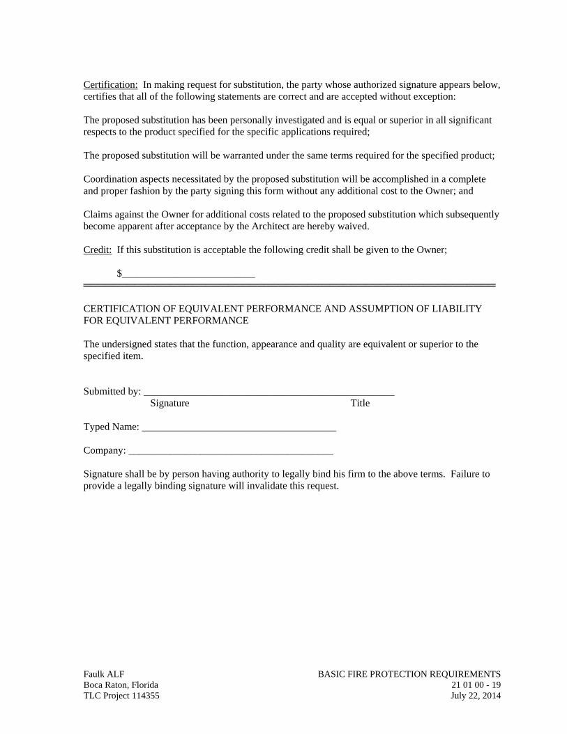
Certification: In making request for substitution, the party whose authorized signature appears below, certifies that all of the following statements are correct and are accepted without exception: The proposed substitution has been personally investigated and is equal or superior in all significant respects to the product specified for the specific applications required; The proposed substitution will be warranted under the same terms required for the specified product; Coordination aspects necessitated by the proposed substitution will be accomplished in a complete and proper fashion by the party signing this form without any additional cost to the Owner; and Claims against the Owner for additional costs related to the proposed substitution which subsequently become apparent after acceptance by the Architect are hereby waived. Credit: If this substitution is acceptable the following credit shall be given to the Owner; $__________________________ ═════════════════════════════════════════════════════════ CERTIFICATION OF EQUIVALENT PERFORMANCE AND ASSUMPTION OF LIABILITY FOR EQUIVALENT PERFORMANCE The undersigned states that the function, appearance and quality are equivalent or superior to the specified item. Submitted by: _________________________________________________ Signature Title Typed Name: ______________________________________ Company: ________________________________________ Signature shall be by person having authority to legally bind his firm to the above terms. Failure to provide a legally binding signature will invalidate this request.
SECTION 21 05 00
COMMON WORK RESULTS FOR FIRE SUPPRESSION
Faulk ALF COMMON WORK RESULTS FOR FIRE SUPPRESSION Boca Raton, Florida 21 05 00 - 1 TLC Project 114355 July 22, 2014
PART 1 - GENERAL
1.01 RELATED DOCUMENTS
A. Drawings and general provisions of the Contract, including General and Supplementary Conditions and Division 01 Specification Sections, apply to this Section.
1.02 SUMMARY
A. This Section includes the following:
1. Piping materials and installation instructions common to most piping systems. 2. Mechanical sleeve seals. 3. Sleeves. 4. Escutcheons. 5. Grout. 6. Fire-suppression equipment and piping demolition. 7. Equipment installation requirements common to equipment sections. 8. Painting and finishing. 9. Concrete bases. 10. Supports and anchorages.
1.03 DEFINITIONS
A. Finished Spaces: Spaces other than mechanical and electrical equipment rooms, furred spaces, pipe chases, unheated spaces immediately below roof, spaces above ceilings, unexcavated spaces, crawlspaces, and tunnels.
B. Exposed, Interior Installations: Exposed to view indoors. Examples include finished occupied spaces and mechanical equipment rooms.
C. Exposed, Exterior Installations: Exposed to view outdoors or subject to outdoor ambient temperatures and weather conditions. Examples include rooftop locations.
D. Concealed, Interior Installations: Concealed from view and protected from physical contact by building occupants. Examples include above ceilings and in chases.
E. Concealed, Exterior Installations: Concealed from view and protected from weather conditions and physical contact by building occupants but subject to outdoor ambient temperatures. Examples include installations within unheated shelters.
F. The following are industry abbreviations for rubber materials:
1. EPDM: Ethylene-propylene-diene terpolymer rubber.
2. NBR: Acrylonitrile-butadiene rubber.
1.04 SUBMITTALS
A. Product Data: For the following:
1. Mechanical sleeve seals. 2. Escutcheons.
B. Welding certificates.
1.05 QUALITY ASSURANCE
A. Steel Support Welding: Qualify processes and operators according to AWS D1.1, "Structural Welding Code--Steel."
B. Steel Pipe Welding: Qualify processes and operators according to ASME Boiler and Pressure Vessel Code: Section IX, "Welding and Brazing Qualifications."
1. Comply with provisions in ASME B31 Series, "Code for Pressure Piping." 2. Certify that each welder has passed AWS qualification tests for welding
processes involved and that certification is current.
C. Electrical Characteristics for Fire-Suppression Equipment: Equipment of higher electrical characteristics may be furnished provided such proposed equipment is approved in writing and connecting electrical services, circuit breakers, and conduit sizes are appropriately modified. If minimum energy ratings or efficiencies are specified, equipment shall comply with requirements.
1.06 DELIVERY, STORAGE, AND HANDLING
A. Deliver pipes and tubes with factory-applied end caps. Maintain end caps through shipping, storage, and handling to prevent pipe end damage and to prevent entrance of dirt, debris, and moisture.
B. Store plastic pipes protected from direct sunlight. Support to prevent sagging and bending.
1.07 COORDINATION
A. Arrange for pipe spaces, chases, slots, and openings in building structure during progress of construction, to allow for fire-suppression installations.
B. Coordinate installation of required supporting devices and set sleeves in poured-in-place concrete and other structural components as they are constructed.
C. Coordinate requirements for access panels and doors for fire-suppression items requiring access that are concealed behind finished surfaces. Access panels and doors are specified in Division 08 Section "Access Doors and Frames."
Faulk ALF COMMON WORK RESULTS FOR FIRE SUPPRESSION Boca Raton, Florida 21 05 00 - 2 TLC Project 114355 July 22, 2014
PART 2 - PRODUCTS
2.01 MANUFACTURERS
A. In other Part 2 articles where subparagraph titles below introduce lists, the following requirements apply for product selection:
1. Manufacturers: Subject to compliance with requirements, provide products by the manufacturers specified.
2.02 PIPE, TUBE, AND FITTINGS
A. Refer to individual Division 21 piping Sections for pipe, tube, and fitting materials and joining methods.
B. Pipe Threads: ASME B1.20.1 for factory-threaded pipe and pipe fittings.
2.03 JOINING MATERIALS
A. Refer to individual Division 21 piping Sections for special joining materials not listed below.
B. Pipe-Flange Gasket Materials: Suitable for chemical and thermal conditions of piping system contents.
1. ASME B16.21, nonmetallic, flat, asbestos-free, 1/8-inch maximum thickness unless thickness or specific material is indicated.
a. Full-Face Type: For flat-face, Class 125, cast-iron and cast-bronze flanges.
b. Narrow-Face Type: For raised-face, Class 250, cast-iron and steel flanges.
2. AWWA C110, rubber, flat face, 1/8 inch thick, unless otherwise indicated; and full-face or ring type, unless otherwise indicated.
C. Flange Bolts and Nuts: ASME B18.2.1, carbon steel, unless otherwise indicated.
D. Plastic, Pipe-Flange Gasket, Bolts, and Nuts: Type and material recommended by piping system manufacturer, unless otherwise indicated.
E. Solid Filler Metals: ASTM B-32, lead-free alloys. Include water flushable flux according to ASTM B 813.
F. Welding Filler Metals: Comply with AWS D10.12 for welding materials appropriate for wall thickness and chemical analysis of steel pipe being welded.
2.04 MECHANICAL SLEEVE SEALS
A. Description: Modular sealing element unit, designed for field assembly, to fill annular space between pipe and sleeve.
Faulk ALF COMMON WORK RESULTS FOR FIRE SUPPRESSION Boca Raton, Florida 21 05 00 - 3 TLC Project 114355 July 22, 2014
1. Manufacturers:
a. Advance Products & Systems, Inc. b. Calpico, Inc. c. Metraflex Co. d. Pipeline Seal and Insulator, Inc
2. Sealing Elements: EPDM interlocking links shaped to fit surface of pipe. Include type and number required for pipe material and size of pipe.
3. Pressure Plates: Carbon steel or Stainless steel. Include two for each sealing element.
4. Connecting Bolts and Nuts: Carbon steel with corrosion-resistant coating or Stainless steel of length required to secure pressure plates to sealing elements. Include one for each sealing element.
2.05 SLEEVES
A. Steel Pipe: ASTM A 53, Type E, Grade B, Schedule 40, galvanized, plain ends.
B. Cast Iron: Cast or fabricated "wall pipe" equivalent to ductile-iron pressure pipe, with plain ends and integral waterstop, unless otherwise indicated.
C. Stack Sleeve Fittings: Manufactured, cast-iron sleeve with integral clamping flange. Include clamping ring and bolts and nuts for membrane flashing.
1. Underdeck Clamp: Clamping ring with set screws.
D. PVC Pipe: ASTM D 1785, Schedule 40.
2.06 PIPING ESCUTCHEONS
A. Description: Manufactured wall and ceiling escutcheons and floor plates, with an ID to closely fit around pipe, tube, and insulation of insulated piping and an OD that completely covers opening.
B. One-Piece, Cast-Brass Type: With set screw.
1. Finish: Polished chrome-plated.
C. Split-Casting, Cast-Brass Type: With concealed hinge and set screw.
1. Finish: Polished chrome-plated.
D. One-Piece, Stamped-Steel Type: With set screw and chrome-plated finish.
E. Split-Plate, Stamped-Steel Type: With concealed hinge, set screw, and chrome-plated finish.
Faulk ALF COMMON WORK RESULTS FOR FIRE SUPPRESSION Boca Raton, Florida 21 05 00 - 4 TLC Project 114355 July 22, 2014
2.07 GROUT
A. Description: ASTM C 1107, Grade B, nonshrink and nonmetallic, dry hydraulic-cement grout.
1. Characteristics: Post-hardening, volume-adjusting, nonstaining, noncorrosive, nongaseous, and recommended for interior and exterior applications.
2. Design Mix: 5000-psi, 28-day compressive strength. 3. Packaging: Premixed and factory packaged.
PART 3 - EXECUTION
A. Refer to Division 01 Section "Cutting and Patching" and Division 02 Section "Selective Structure Demolition" for general demolition requirements and procedures.
B. Disconnect, demolish, and remove fire-suppression systems, equipment, and components indicated to be removed.
1. Piping to Be Removed: Remove portion of piping indicated to be removed and cap or plug remaining piping with same or compatible piping material.
2. Equipment to Be Removed: Disconnect and cap services and remove equipment.
C. If pipe, insulation, or equipment to remain is damaged in appearance or is unserviceable, remove damaged or unserviceable portions and replace with new products of equal capacity and quality.
3.02 PIPING SYSTEMS - COMMON REQUIREMENTS
A. Install piping according to the following requirements and Division 21 Sections specifying piping systems.
B. Drawing plans, schematics, and diagrams indicate general location and arrangement of piping systems. Indicated locations and arrangements were used to size pipe and calculate friction loss, expansion, pump sizing, and other design considerations. Install piping as indicated unless deviations to layout are approved on Coordination Drawings.
C. Install piping in concealed locations, unless otherwise indicated and except in equipment rooms and service areas.
D. Install piping indicated to be exposed and piping in equipment rooms and service areas at right angles or parallel to building walls. Diagonal runs are prohibited unless specifically indicated otherwise.
E. Install piping above accessible ceilings to allow sufficient space for ceiling panel removal.
F. Install piping to permit valve servicing.
Faulk ALF COMMON WORK RESULTS FOR FIRE SUPPRESSION Boca Raton, Florida 21 05 00 - 5 TLC Project 114355 July 22, 2014
G. Install piping at indicated slopes.
H. Install piping free of sags and bends.
I. Install fittings for changes in direction and branch connections.
J. Install piping to allow application of insulation.
K. Select system components with pressure rating equal to or greater than system operating pressure.
L. Install escutcheons for penetrations of walls, ceilings, and floors according to the following:
1. New Piping:
a. Bare Piping at Wall Ceiling and Floor Penetrations in Finished Spaces: One-piece, cast-brass type with polished chrome-plated finish.
M. Permanent sleeves are not required for holes formed by removable PE sleeves.
N. Install sleeves for pipes passing through concrete and masonry walls, gypsum-board partitions, and concrete floor and roof slabs.
1. Cut sleeves to length for mounting flush with both surfaces.
a. Exception: Extend sleeves installed in floors of mechanical equipment areas or other wet areas 2 inches above finished floor level. Extend cast-iron sleeve fittings below floor slab as required to secure clamping ring if ring is specified.
2. Install sleeves in new walls and slabs as new walls and slabs are constructed.
3. Install sleeves that are large enough to provide 1/4-inch annular clear space between sleeve and pipe or pipe insulation. Use the following sleeve materials:
a. Steel Pipe Sleeves. b. Stack Sleeve Fittings: For pipes penetrating floors with membrane
waterproofing. Secure flashing between clamping flanges. Install section of cast-iron soil pipe to extend sleeve to 2 inches above finished floor level. Refer to Division 07 Section "Sheet Metal Flashing and Trim" for flashing.
1) Seal space outside of sleeve fittings with grout.
4. Except for underground wall penetrations, seal annular space between sleeve and pipe or pipe insulation, using joint sealants appropriate for size, depth, and location of joint. Refer to Division 07 Section "Joint Sealants" for materials and installation.
Faulk ALF COMMON WORK RESULTS FOR FIRE SUPPRESSION Boca Raton, Florida 21 05 00 - 6 TLC Project 114355 July 22, 2014
O. Aboveground, Exterior-Wall Pipe Penetrations: Seal penetrations using sleeves and mechanical sleeve seals. Select sleeve size to allow for 1-inch annular clear space between pipe and sleeve for installing mechanical sleeve seals.
1. Install steel pipe for sleeves smaller than 6 inches in diameter. 2. Install cast-iron "wall pipes" for sleeves 6 inches and larger in diameter. 3. Mechanical Sleeve Seal Installation: Select type and number of sealing
elements required for pipe material and size. Position pipe in center of sleeve. Assemble mechanical sleeve seals and install in annular space between pipe and sleeve. Tighten bolts against pressure plates that cause sealing elements to expand and make watertight seal.
P. Underground, Exterior-Wall Pipe Penetrations: Install cast-iron "wall pipes" for sleeves. Seal pipe penetrations using mechanical sleeve seals. Select sleeve size to allow for 1-inch annular clear space between pipe and sleeve for installing mechanical sleeve seals.
1. Mechanical Sleeve Seal Installation: Select type and number of sealing elements required for pipe material and size. Position pipe in center of sleeve. Assemble mechanical sleeve seals and install in annular space between pipe and sleeve. Tighten bolts against pressure plates that cause sealing elements to expand and make watertight seal.
Q. Fire-Barrier Penetrations: Maintain indicated fire rating of walls, partitions, ceilings, and floors at pipe penetrations. Seal pipe penetrations with firestop materials. Refer to Division 07 Section "Penetration Firestopping" for materials.
R. Verify final equipment locations for roughing-in.
S. Refer to equipment specifications in other Sections of these Specifications for roughing-in requirements.
3.03 PIPING JOINT CONSTRUCTION
A. Join pipe and fittings according to the following requirements and Division 21 Sections specifying piping systems.
B. Ream ends of pipes and tubes and remove burrs. Bevel plain ends of steel pipe.
C. Remove scale, slag, dirt, and debris from inside and outside of pipe and fittings before assembly.
D. Soldered Joints: Apply ASTM B 813, water flushable flux, unless otherwise indicated, to tube end. Construct joints according to ASTM B 828 or CDA’s “Copper Tube Handbook”, using lead free solder alloy complying with ASTM B 32.
E. Threaded Joints: Thread pipe with tapered pipe threads according to ASME B1.20.1. Cut threads full and clean using sharp dies. Ream threaded pipe ends to remove burrs and restore full ID. Join pipe fittings and valves as follows:
Faulk ALF COMMON WORK RESULTS FOR FIRE SUPPRESSION Boca Raton, Florida 21 05 00 - 7 TLC Project 114355 July 22, 2014
Faulk ALF COMMON WORK RESULTS FOR FIRE SUPPRESSION Boca Raton, Florida 21 05 00 - 8 TLC Project 114355 July 22, 2014
1. Apply appropriate tape or thread compound to external pipe threads unless dry seal threading is specified.
2. Damaged Threads: Do not use pipe or pipe fittings with threads that are corroded or damaged. Do not use pipe sections that have cracked or open welds.
F. Welded Joints: Construct joints according to AWS D10.12, using qualified processes and welding operators according to Part 1 "Quality Assurance" Article.
G. Flanged Joints: Select appropriate gasket material, size, type, and thickness for service application. Install gasket concentrically positioned. Use suitable lubricants on bolt threads.
3.04 PAINTING
A. Painting of fire-suppression systems, equipment, and components is specified in Division 09 Sections "Interior Painting" and "Exterior Painting."
B. Damage and Touchup: Repair marred and damaged factory-painted finishes with materials and procedures to match original factory finish.
3.05 CONCRETE BASES
A. Concrete Bases: Shall be coordinated with Division 03.
3.06 ERECTION OF METAL SUPPORTS AND ANCHORAGES
A. Refer to Division 05 Section "Metal Fabrications" for structural steel.
B. Cut, fit, and place miscellaneous metal supports accurately in location, alignment, and elevation to support and anchor fire-suppression materials and equipment.
C. Field Welding: Comply with AWS D1.1.
3.07 GROUTING
A. Mix and install grout for fire-suppression equipment base bearing surfaces, pump and other equipment base plates, and anchors.
B. Clean surfaces that will come into contact with grout. C. Provide forms as required for placement of grout. D. Avoid air entrapment during placement of grout. E. Place grout, completely filling equipment bases. F. Place grout on concrete bases and provide smooth bearing surface for equipment. G. Place grout around anchors. H. Cure placed grout.
END OF SECTION 21 05 00
SECTION 21 05 53 IDENTIFICATION FOR FIRE SUPPRESSION PIPING & EQUIPMENT
Faulk ALF IDENTIFICATION FOR FIRE SUPPRESSION PIPING & EQUIP Boca Raton, Florida 21 05 53 - 1 TLC Project 114355 July 22, 2014
PART 1 - GENERAL
1.01 RELATED DOCUMENTS
A. Drawings and general provisions of the Contract, including General and Supplementary Conditions and Division 01 Specification Sections, apply to this Section.
1.02 SUMMARY
A. Section Includes:
1. Equipment labels. 2. Warning signs and labels. 3. Pipe labels. 4. Stencils. 5. Valve tags. 6. Warning tags.
1.03 ACTION SUBMITTALS
A. Product Data: For each type of product.
B. Samples: For color, letter style, and graphic representation required for each identification material and device.
C. Equipment-Label Schedule: Include a listing of all equipment to be labeled and the proposed content for each label.
D. Valve Schedules: Valve numbering scheme.
1.04 CLOSEOUT SUBMITTALS
A. Maintenance Data: For each piping system to include in maintenance manuals.
PART 2 - PRODUCTS
2.01 EQUIPMENT LABELS
A. Metal Labels for Equipment:
1. Material and Thickness: Brass, 0.032 inch thick, with predrilled holes for attachment hardware.
2. Letter Color: White. 3. Background Color: Red. 4. Minimum Label Size: Length and width vary for required label content, but not less
than 2-1/2 by 3/4 inch. 5. Minimum Letter Size: 1/4 inch for name of units if viewing distance is less than 24
inches, 1/2 inch for viewing distances up to 72 inches, and proportionately larger
lettering for greater viewing distances. Include secondary lettering two-thirds to three-fourths the size of principal lettering.
6. Fasteners: Stainless-steel self-tapping screws. 7. Adhesive: Contact-type permanent adhesive, compatible with label and with
substrate.
B. Plastic Labels for Equipment:
1. Material and Thickness: Multilayer, multicolor, plastic labels for mechanical engraving, 1/16 inch thick, with predrilled holes for attachment hardware.
2. Letter Color: White. 3. Background Color: Red. 4. Maximum Temperature: Able to withstand temperatures up to 160 deg F. 5. Minimum Label Size: Length and width vary for required label content, but not less
than 2-1/2 by 3/4 inch. 6. Minimum Letter Size: 1/4 inch for name of units if viewing distance is less than 24
inches, 1/2 inch for viewing distances up to 72 inches, and proportionately larger lettering for greater viewing distances. Include secondary lettering two-thirds to three-fourths the size of principal lettering.
7. Fasteners: Stainless-steel self-tapping screws. 8. Adhesive: Contact-type permanent adhesive, compatible with label and with
substrate.
C. Label Content: Include equipment's Drawing designation or unique equipment number, Drawing numbers where equipment is indicated (plans, details, and schedules), and the Specification Section number and title where equipment is specified.
D. Equipment-Label Schedule: For each item of equipment to be labeled, on 8-1/2-by-11-inch bond paper. Tabulate equipment identification number and identify Drawing numbers where equipment is indicated (plans, details, and schedules) and the Specification Section number and title where equipment is specified. Equipment schedule shall be included in operation and maintenance data.
2.02 WARNING SIGNS AND LABELS
A. A. Material and Thickness: Multilayer, multicolor, plastic labels for mechanical engraving, 1/16 inch thick, with predrilled holes for attachment hardware.
B. Letter Color: White.
C. Background Color: Red.
D. Maximum Temperature: Able to withstand temperatures up to 160 deg F.
E. Minimum Label Size: Length and width vary for required label content, but not less than 2-1/2 by 3/4 inch.
F. Minimum Letter Size: 1/4 inch for name of units if viewing distance is less than 24 inches, 1/2 inch for viewing distances up to 72 inches, and proportionately larger lettering for greater viewing distances. Include secondary lettering two-thirds to three-fourths the size of principal lettering.
Faulk ALF IDENTIFICATION FOR FIRE SUPPRESSION PIPING & EQUIP Boca Raton, Florida 21 05 53 - 2 TLC Project 114355 July 22, 2014
G. Fasteners: Stainless-steel self-tapping screws.
H. Adhesive: Contact-type permanent adhesive, compatible with label and with substrate.
I. Label Content: Include caution and warning information, plus emergency notification instructions.
2.03 PIPE LABELS
A. General Requirements for Manufactured Pipe Labels: Preprinted, color-coded, with lettering indicating service and showing flow direction.
B. Pretensioned Pipe Labels: Precoiled, semirigid plastic formed to cover full circumference of pipe and to attach to pipe without fasteners or adhesive.
C. Self-Adhesive Pipe Labels: Printed plastic with contact-type, permanent-adhesive backing.
D. Pipe-Label Contents: Include identification of piping service using same designations or abbreviations as used on Drawings; pipe size; and an arrow indicating flow direction.
1. Flow-Direction Arrows: Integral with piping-system service lettering to accommodate both directions or as separate unit on each pipe label to indicate flow direction.
2. Lettering Size: At least 1-1/2 inches high.
E. Pipe-Label Colors:
1. Background Color: Red. 2. Letter Color: White.
2.04 STENCILS
A. Stencils: Prepared with letter sizes according to ASME A13.1 for piping; and minimum letter height of 3/4 inch for access panel and door labels, equipment labels, and similar operational instructions.
1. Stencil Material: Aluminum. 2. Stencil Paint: Exterior, gloss, acrylic enamel black unless otherwise indicated. Paint
may be in pressurized spray-can form. 3. Identification Paint: Exterior, acrylic enamel in colors according to ASME A13.1
unless otherwise indicated.
2.05 VALVE TAGS
A. Valve Tags: Stamped or engraved with 1/4-inch letters for piping-system abbreviation and 1/2-inch numbers.
1. Tag Material: Brass, 0.032 inch thick, with predrilled holes for attachment hardware. 2. Fasteners: Brass wire-link chain. 3. Valve-Tag Color: Red. 4. Letter Color: White.
Faulk ALF IDENTIFICATION FOR FIRE SUPPRESSION PIPING & EQUIP Boca Raton, Florida 21 05 53 - 3 TLC Project 114355 July 22, 2014
B. Valve Schedules: For each piping system, on 8-1/2-by-11-inch bond paper. Tabulate valve number, piping system, system abbreviation (as shown on valve tag), location of valve (room or space), normal-operating position (open, closed, or modulating), and variations for identification. Mark valves for emergency shutoff and similar special uses.
1. Valve-tag schedule shall be included in operation and maintenance data.
2.06 WARNING TAGS
A. Warning Tags: Preprinted or partially preprinted, accident-prevention tags, of plasticized card stock with matte finish suitable for writing.
1. Size: 3 by 5-1/4 inches minimum. 2. Fasteners: Brass grommet and wire. 3. Nomenclature: Large-size primary caption such as "DANGER," "CAUTION," or
"DO NOT OPERATE." 4. Color: Yellow background with black lettering.
PART 3 - EXECUTION
3.01 PREPARATION
A. Clean piping and equipment surfaces of substances that could impair bond of identification devices, including dirt, oil, grease, release agents, and incompatible primers, paints, and encapsulants.
3.02 LABEL INSTALLATION
A. Coordinate installation of identifying devices with completion of covering and painting of surfaces where devices are to be applied.
B. Coordinate installation of identifying devices with locations of access panels and doors.
C. Install or permanently fasten labels on each major item of mechanical equipment.
D. Locate equipment labels where accessible and visible.
E. Piping Color-Coding: Painting of piping is specified in Division 09 Section "High-Performance Coatings."
F. Stenciled Pipe-Label Option: Stenciled labels may be provided instead of manufactured pipe labels, at Installer's option. Install stenciled pipe labels, complying with ASME A13.1, with painted, color-coded bands on each piping system.
1. Identification Paint: Use for contrasting background. 2. Stencil Paint: Use for pipe marking.
G. Pipe-Label Locations: Locate pipe labels where piping is exposed or above accessible ceilings in finished spaces; machine rooms; accessible maintenance spaces such as shafts, tunnels, and plenums; and exterior exposed locations as follows:
1. Near each valve and control device. Faulk ALF IDENTIFICATION FOR FIRE SUPPRESSION PIPING & EQUIP Boca Raton, Florida 21 05 53 - 4 TLC Project 114355 July 22, 2014
Faulk ALF IDENTIFICATION FOR FIRE SUPPRESSION PIPING & EQUIP Boca Raton, Florida 21 05 53 - 5 TLC Project 114355 July 22, 2014
2. Near each branch connection excluding short takeoffs. Where flow pattern is not obvious, mark each pipe at branch.
3. Near penetrations through walls, floors, ceilings, and inaccessible enclosures. 4. At access doors, manholes, and similar access points that permit view of concealed
piping. 5. Near major equipment items and other points of origination and termination. 6. Spaced at maximum intervals of 50 feet along each run. Reduce intervals to 25 feet
in areas of congested piping and equipment. 7. On piping above removable acoustical ceilings. Omit intermediately spaced labels.
3.03 VALVE-TAG INSTALLATION
A. Install tags on valves and control devices in piping systems. List tagged valves in a valve-tag schedule.
B. Valve-Tag Application Schedule: Tag valves according to size, shape, and with captions similar to those indicated in "Valve-Tag Size and Shape" Subparagraph below:
1. Valve-Tag Size and Shape:
a. Fire-Suppression Standpipe: 2 inches, square.
b. Wet-Pipe Sprinkler System: 2 inches, square.
c. Dry-Pipe Sprinkler System: 2 inches, square.
d. Foam-Water System: 2 inches, square.
e. Clean-Agent Fire-Extinguishing System: 2 inches, square.
3.04 WARNING-TAG INSTALLATION
A. Write required message on, and attach warning tags to, equipment and other items where required.
END OF SECTION 21 05 53
SECTION 21 13 13
WET PIPE SPRINKLER SYSTEMS
Faulk ALF WET PIPE SPRINKLER SYSTEMS Boca Raton, Florida 21 13 13 - 1 TLC Project 114355 July 22, 2014
PART 1 - GENERAL
1.01 RELATED DOCUMENTS
A. Drawings and general provisions of the Contract, including General and Supplementary Conditions and Division 01 Specification Sections, apply to this Section.
1.02 SUMMARY
A. Section Includes:
1. Pipes, fittings, and specialties. 2. Fire-protection valves. 3. Sprinklers.
1.03 DEFINITIONS
A. Standard-Pressure Sprinkler Piping: Wet-pipe sprinkler system piping designed to operate at working pressure of 175 psig maximum.
1.04 SYSTEM DESCRIPTIONS
A. Wet-Pipe Sprinkler System: Automatic sprinklers are attached to piping containing water and that is connected to water supply through alarm valve. Water discharges immediately from sprinklers when they are opened. Sprinklers open when heat melts fusible link or destroys frangible device. Hose connections are included if indicated.
1.05 PERFORMANCE REQUIREMENTS
A. Standard-Pressure Piping System Component: Listed for 175-psig minimum working pressure.
B. Sprinkler system shall be approved by authorities having jurisdiction.
1. Margin of Safety for Available Water Flow and Pressure: 10 P.S.I. 2. Sprinkler Occupancy Hazard Classifications refer to drawings.
1.06 SUBMITTALS
A. Product Data: For each type of product indicated. Include rated capacities, operating characteristics, electrical characteristics, and furnished specialties and accessories.
B. Shop Drawings: For wet-pipe sprinkler systems. Include plans, elevations, sections, details, and attachments to other work, per NFPA 13, Chapter 14.
C. Hydraulic Calculations.
D. Sprinkler System design data is indicated on the fire protection drawings.
1.07 QUALITY ASSURANCE
A. Installer Qualifications:
1. Installer's responsibilities include fabricating, and installing sprinkler systems and providing working plans per NFPA 13. Base calculations on results of fire-hydrant flow test.
B. Welding Qualifications: Qualify procedures and operators according to ASME Boiler and Pressure Vessel Code.
C. Electrical Components, Devices, and Accessories: Listed and labeled as defined in NFPA 70, by a qualified testing agency, and marked for intended location and application.
D. NFPA Standards: Sprinkler system equipment, specialties, accessories, installation, and testing shall comply with the following:
1. NFPA 13, Installation of Sprinkler Systems.
1.08 PROJECT CONDITIONS
A. Interruption of Existing Sprinkler Service: Do not interrupt sprinkler service to facilities occupied by Owner or others unless permitted under the following conditions and then only after arranging to provide temporary sprinkler service according to requirements indicated:
1. Notify Architect and Construction Manager no fewer than five days in advance of proposed interruption of sprinkler service.
2. Do not proceed with interruption of sprinkler service without Architect's and Construction Manager's written permission.
1.09 COORDINATION
A. Coordinate layout and installation of sprinklers with other construction that penetrates ceilings, including light fixtures, HVAC equipment, and partition assemblies.
PART 2 - PRODUCTS
2.01 STEEL PIPE AND FITTINGS
A. Standard Weight, Black-Steel Schedule 40 Pipe: ASTM A 53/A 53M or ASTM A 135, for piping 2” and smaller. Black steel Schedule 10 for piping 2-1/2” and larger.
B. Galvanized- and Black-Steel Pipe Nipples: ASTM A 733, made of ASTM A 53/A 53M, standard-weight, seamless steel pipe with threaded ends.
C. Galvanized and Uncoated, Steel Couplings: ASTM A 865, threaded.
Faulk ALF WET PIPE SPRINKLER SYSTEMS Boca Raton, Florida 21 13 13 - 2 TLC Project 114355 July 22, 2014
D. Galvanized and Uncoated, Gray-Iron Threaded Fittings: ASME B16.4, Class 125, standard pattern.
E. Grooved-Joint, Steel-Pipe Appurtenances:
1. Manufacturers: Subject to compliance with requirements, available manufacturers offering products that may be incorporated into the Work include, but are not limited to, the following:
a. Tyco Fire & Building Products LP. b. Victaulic Company. c. Anvil Star Piping Inc.
2. Pressure Rating: 175 psig unless otherwise noted.
3. Galvanized and Uncoated, Grooved-End Fittings for Steel Piping: ASTM A 47/A 47M, malleable-iron casting or ASTM A 536, ductile-iron casting; with dimensions matching steel pipe.
4. Grooved-End-Pipe Couplings for Steel Piping: AWWA C606 and UL 213, rigid pattern, unless otherwise indicated, for steel-pipe dimensions. Include ferrous housing sections, EPDM-rubber gasket, and bolts and nuts.
2.02 NON-FERROUS PIPING (MRI Area)
A. Pressure pipe shall be Type L copper pipe conforming to ASTM B-88, annealed, seamless hard pipe. Listed for fire service.
B. Fittings: Shall be wrought or cast brass conforming to ANSI B16.22 or ANSI B16.15. Listed for fire service.
C. Flanges: Shall be wrought or cast brass conforming to B16.24 rated for 300 pounds. Gasket flange bolts shall be brass conforming to ASTM A307 with Hex nuts conforming to ANSI B18.2. Listed for fire service.
D. Couplings: Rolled groove couplings conforming to UL listed FM approved.
E. Dielectric Isolator: Provide dielectric couplings where dissimilar metals exist. Couplings shall be rated for 175 psi, UL listed or FM approved.
2.03 PIPING JOINING MATERIALS
A. Pipe-Flange Gasket Materials: AWWA C110, rubber, flat face, 1/8 inch thick or ASME B16.21, nonmetallic and asbestos free.
1. Class 125, Cast-Iron Flanges and Class 150, Bronze Flat-Face Flanges: Full-face gaskets.
2. Class 250, Cast-Iron Flanges and Class 300, Steel Raised-Face Flanges: Ring-type gaskets.
Faulk ALF WET PIPE SPRINKLER SYSTEMS Boca Raton, Florida 21 13 13 - 3 TLC Project 114355 July 22, 2014
B. Metal, Pipe-Flange Bolts and Nuts: ASME B18.2.1, carbon steel unless otherwise indicated.
C. Brazing Filler Metals: AWS A5.8/A5.8M, BCuP Series, copper-phosphorus alloys for general-duty brazing unless otherwise indicated.
D. Welding Filler Metals: Comply with AWS D10.12M/D10.12 for welding materials appropriate for wall thickness and chemical analysis of steel pipe being welded.
2.04 LISTED FIRE-PROTECTION VALVES
A. General Requirements:
1. Valves shall be UL listed or FM approved. 2. Minimum Pressure Rating for Standard-Pressure Piping: 175 psig.
B. Ball Valves:
1. Standard: UL 1091 except with ball instead of disc.
2. Valves NPS 1-1/2 and Smaller: Bronze body with threaded ends.
3. Valves NPS 2 and NPS 2-1/2: Bronze body with threaded ends or ductile-iron body with grooved ends.
4. Valves NPS 3: Ductile-iron body with grooved ends.
C. Check Valves:
1. Standard: UL 312. 2. Pressure Rating: 300 psig. 3. Type: Swing check. 4. Body Material: Cast iron. 5. End Connections: Flanged or grooved.
D. Iron Butterfly Valves:
1. Manufacturers: Subject to compliance with requirements, provide products by one of the following:
a. Anvil International, Inc. b. Kennedy Valve; a division of McWane, Inc. c. Milwaukee Valve Company. d. NIBCO INC. e. Tyco Fire & Building Products LP. f. Victaulic Company.
2. Standard: UL 1091. 3. Pressure Rating: 175 psig. 4. Body Material: Cast or ductile iron. 5. Style: Lug or wafer. 6. End Connections: Grooved.
Faulk ALF WET PIPE SPRINKLER SYSTEMS Boca Raton, Florida 21 13 13 - 4 TLC Project 114355 July 22, 2014
2.05 SPRINKLERS
A. Manufacturers: Subject to compliance with requirements, available manufacturers offering products that may be incorporated into the work include, but are not limited to, the following:
1. Reliable Automatic Sprinkler Co., Inc. 2. Tyco Fire & Building Products LP. 3. Victaulic Company. 4. Viking Corporation.
B. General Requirements:
1. Standard: UL's "Fire Protection Equipment Directory" listing or "Approval Guide," published by FM Global, listing.
2. Pressure Rating for Residential Sprinklers: 175 psig maximum. 3. Pressure Rating for Automatic Sprinklers: 175 psig minimum. 4. Refer to drawings for sprinkler types and applicable locations.
C. Sprinkler Finishes: See Drawings
D. Special Coatings: See Drawings
2.06 GROUT
A. Standard: ASTM C 1107, Grade B, posthardening and volume adjusting, dry, hydraulic-cement grout.
B. Characteristics: Nonshrink, and recommended for interior and exterior applications.
C. Design Mix: 5000-psi, 28-day compressive strength.
D. Packaging: Premixed and factory packaged.
2.07 HANGERS AND SUPPORTS
A. Support piping with UL and FM approved hangers:
1. All hangers, rods and supports shall be galvanized. 2. Provide threaded rods and anchors. 3. Powder driven inserts and fasteners shall not be allowed.
4. Manufacturers: Subject to compliance with requirements, provide one of the following:
a. Anvil International b. Tolco/NIBCO, Inc. c. Globe Pipe Hangers, Inc. d. Caddy/Erico Products, Inc. e. Tyco Fire and Building Products LP
Faulk ALF WET PIPE SPRINKLER SYSTEMS Boca Raton, Florida 21 13 13 - 5 TLC Project 114355 July 22, 2014
PART 3 - EXECUTION
3.01 PREPARATION
A. Perform fire-hydrant flow test according to NFPA 13 and NFPA 291. Use results for system design calculations required in "Quality Assurance" Article.
B. Report test results promptly and in writing.
3.02 SERVICE-ENTRANCE PIPING
A. Connect sprinkler piping to water-service piping for service entrance to building.
B. Install shutoff valve, backflow preventer, pressure gage, drain, and other accessories indicated at connection to water-service piping.
3.03 PIPING INSTALLATION
A. Locations and Arrangements: Drawing plans, schematics, and diagrams indicate general location and arrangement of piping. Install piping as indicated, as far as practical.
1. Deviations from approved working plans for piping require written approval from authorities having jurisdiction. File written approval with Architect before deviating from approved working plans.
B. Piping Standard: Comply with requirements for installation of sprinkler piping in NFPA 13.
C. Use listed fittings to make changes in direction, branch takeoffs from mains, and reductions in pipe sizes.
D. Install unions adjacent to each valve in pipes NPS 2 and smaller.
E. Install flanges, flange adapters, or couplings for grooved-end piping on valves, apparatus, and equipment having NPS 2-1/2 and larger end connections.
F. Install "Inspector's Test Connections" in sprinkler system piping, complete with shutoff valve, and sized and located according to NFPA 13.
G. Install sprinkler piping with drains for complete system drainage.
H. Install sprinkler control valves, test assemblies, and drain risers adjacent to standpipes when sprinkler piping is connected to standpipes.
I. Install automatic (ball drip) drain valve at each check valve for fire-department connection, to drain piping between fire-department connection and check valve. Install drain piping to and spill over floor drain or to outside building.
J. Install alarm devices in piping systems.
Faulk ALF WET PIPE SPRINKLER SYSTEMS Boca Raton, Florida 21 13 13 - 6 TLC Project 114355 July 22, 2014
K. Install hangers and supports for sprinkler system piping according to NFPA 13. Comply with requirements for hanger materials in NFPA 13. Powder driven inserts are not allowed.
L. Install pressure gages on riser or feed main, at each sprinkler test connection, and at top of each standpipe. Include pressure gages with connection not less than NPS 1/4 and with soft metal seated globe valve, arranged for draining pipe between gage and valve. Install gages to permit removal, and install where they will not be subject to freezing.
M. Pressurize and check preaction sprinkler system piping and air-pressure maintenance devices.
N. Fill sprinkler system piping with water.
3.04 PAINTING OF PIPING
A. All exposed black steel pipe shall be painted. All pipe surfaces shall be cleaned from grease and debris, primed and painted red unless otherwise noted on Contract Documents.
3.05 JOINT CONSTRUCTION
A. Install couplings, flanges, flanged fittings, unions, nipples, and transition and special fittings that have finish and pressure ratings same as or higher than system's pressure rating for aboveground applications unless otherwise indicated.
B. Install unions adjacent to each valve in pipes NPS 2 and smaller.
C. Install flanges, flange adapters, or couplings for grooved-end piping on valves, apparatus, and equipment having NPS 2-1/2 and larger end connections.
D. Ream ends of pipes and tubes and remove burrs. Bevel plain ends of steel pipe.
E. Remove scale, slag, dirt, and debris from inside and outside of pipes, tubes, and fittings before assembly.
F. Flanged Joints: Select appropriate gasket material in size, type, and thickness suitable for water service. Join flanges with gasket and bolts according to ASME B31.9.
G. Threaded Joints: Thread pipe with tapered pipe threads according to ASME B1.20.1. Cut threads full and clean using sharp dies. Ream threaded pipe ends to remove burrs and restore full ID. Join pipe fittings and valves as follows:
1. Apply appropriate tape or thread compound to external pipe threads. 2. Damaged Threads: Do not use pipe or pipe fittings with threads that are
corroded or damaged.
H. Welded Joints: Construct joints according to AWS D10.12M/D10.12, using qualified processes and welding operators according to "Quality Assurance" Article.
Faulk ALF WET PIPE SPRINKLER SYSTEMS Boca Raton, Florida 21 13 13 - 7 TLC Project 114355 July 22, 2014
1. Shop weld pipe joints where welded piping is indicated. Do not use welded joints for galvanized-steel pipe.
I. Steel-Piping, Roll-Grooved Joints: Roll rounded-edge groove in end of pipe according to AWWA C606. Assemble coupling with housing, gasket, lubricant, and bolts. Join steel pipe and grooved-end fittings according to AWWA C606 for steel-pipe grooved joints.
J. Dissimilar-Material Piping Joints: Make joints using adapters compatible with materials of both piping systems.
3.06 VALVE AND SPECIALTIES INSTALLATION
A. Install listed fire-protection valves, trim and drain valves, specialty valves and trim, controls, and specialties according to NFPA 13 and authorities having jurisdiction.
B. Install listed fire-protection shutoff valves supervised open, located to control sources of water supply except from fire-department connections. Install permanent identification signs indicating portion of system controlled by each valve.
C. Install check valve in each water-supply connection. Install backflow preventers instead of check valves in potable-water-supply sources.
D. Specialty Valves:
1. General Requirements: Install in vertical position for proper direction of flow, in main supply to system.
2. Alarm Valves: Include bypass check valve and retarding chamber drain-line connection.
3.07 SPRINKLER INSTALLATION
A. Install sprinklers in suspended ceilings in center of acoustical ceiling panels. Sprinklers shall be centered in tile.
B. Sprinkler Head Location: Sprinkler heads shall be installed no closer than 4 inches to any Ceiling grid or wall.
C. Install dry-type sprinklers with water supply from heated space. Do not install pendent or sidewall, wet-type sprinklers in areas subject to freezing.
3.08 ESCUTCHEON INSTALLATION
A. Install escutcheons for penetrations of walls, ceilings, and floors.
B. Escutcheons for Piping:
1. Piping with Fitting or Sleeve Protruding from Wall: deep pattern.
2. Bare Piping at Wall and Floor Penetrations in Finished Spaces: cast brass with polished chrome-plated finish.
Faulk ALF WET PIPE SPRINKLER SYSTEMS Boca Raton, Florida 21 13 13 - 8 TLC Project 114355 July 22, 2014
Faulk ALF WET PIPE SPRINKLER SYSTEMS Boca Raton, Florida 21 13 13 - 9 TLC Project 114355 July 22, 2014
3. Bare Piping at Ceiling Penetrations in Finished Spaces cast brass with polished chrome-plated finish.
3.09 IDENTIFICATION
A. Install labeling and pipe markers on equipment and piping according to requirements in NFPA 13.
B. Identify system components, wiring, cabling, and terminals. Comply with requirements for identification specified in Division 26 Section "Identification for Electrical Systems."
3.10 FIELD QUALITY CONTROL
A. Perform tests and inspections.
B. Tests and Inspections:
1. Leak Test: After installation, charge systems and test for leaks. Repair leaks and retest until no leaks exist.
2. Test and adjust controls and safeties. Replace damaged and malfunctioning controls and equipment.
3. Flush, test, and inspect sprinkler systems according to NFPA 13, "Systems Acceptance" Chapter.
4. Energize circuits to electrical equipment and devices. 5. Start and run excess-pressure pumps. 6. Coordinate with fire-alarm tests. Operate as required. 7. Coordinate with fire-pump tests. Operate as required. 8. Verify that equipment hose threads are same as local fire-department equipment.
C. Sprinkler piping system will be considered defective if it does not pass tests and inspections.
D. Prepare test and inspection reports.
END OF SECTION 21 13 13
SECTION 22 05 00
BASIC MECHANICAL REQUIREMENTS
Faulk ALF BASIC MECHANICAL REQUIREMENTS Boca Raton, Florida 22 05 00 - 1 TLC Project 114355 July 22, 2014
PART 1 - GENERAL
1.01 RELATED DOCUMENTS
A. Basic Requirements: Requirements of the Contract Forms, Conditions of the Contract, Specifications, Drawings, and Addenda and Contract Modifications (the Contract Documents), apply to the requirements of each Section of Division 22.
B. Conflicts: Nothing contained in this Section shall be construed to conflict in any way with
other provisions or requirements of the Contract documents. The intent is that this Section will take precedence. Where differences arise, the Architect shall decide which directions or instructions take precedence.
1.02 SUMMARY
A. General: Unless an item is specifically mentioned as being provided by others, the requirements of these Contract Documents shall be completed. The systems, equipment, devices and accessories shall be installed, finished, tested and adjusted for continuous and proper operation. Any apparatus, material or device not shown on the Drawings but mentioned in these Specifications, or vice versa, or any incidental accessories necessary to make the project complete and operational in all respects, shall be furnished, delivered and installed without additional expense to the Owner. Include all materials, equipment, supervision, operation, methods and labor for the fabrication, installation, start-up and tests necessary for complete and properly functioning systems.
1.03 APPLICABLE STANDARDS
A. Code Compliance: Refer to Division 1. As a minimum, unless otherwise indicated, comply with all rules, regulations, standards, codes, ordinances and laws of local, state and federal governments and the amendments and interpretation of such rules, regulations, standards, codes, ordinances and laws of local, state and federal governments by the authorities having lawful jurisdiction.
B. ADA: Comply with the requirements of the Americans with Disabilities Act (ADA).
C. Florida Building Code 2010 Edition: Conform in strict compliance to the Florida Building
Code (FBC) and the amendments which are enforced by the local authority having jurisdiction.
1. Florida Building Code – Plumbing 2010 Edition. 2. FGI - Guidelines for Design and Construction of Healthcare Facilities, 2010 Edition.
D. NATIONAL FIRE PROTECTION (NFPA) Standards:
1. NFPA-99, Standard for Health Care Facilities, 2005 Revision.
E. Notification: Comply with all of the requirements of the Federal "Right-To-Know" Regulations and the Florida "Right-To-Know" Law and provide notification to all parties concerned as to the use of toxic substances.
F. Owner Design Guidelines: Comply with all the requirements of the latest Owner MEP
Engineering Design Guidelines and the latest Owner Architectural Construction Standards. 1.04 DRAWINGS AND SPECIFICATIONS
A. Intent: The intent of the drawings and specifications is to establish minimum acceptable quality standards for materials, equipment and workmanship, and to provide operable mechanical systems complete in every respect.
B. Equipment Placement: The drawings are diagrammatic, intended to show general
arrangement, capacity and location of various components, equipment and devices. Each location shall be determined by reference to the general building plans and by actual measurements in the building as built. Reasonable changes in locations ordered by the Architect prior to the performance of the affected Work shall be provided at no additional cost to the Owner.
C. Drawing Scale: Due to the small scale of the drawings, and to unforeseen job conditions, all
required offsets, transitions and fittings may not be shown but shall be provided at no additional cost.
D. Conflict: In the event of a conflict, the Architect will render an interpretation in accordance
with the General Conditions. 1.05 DEFINITIONS
A. Provide/Install: The word "provide" shall mean furnish, install, connect, test, complete, and leave ready for operation. The word "install" where used in conjunction with equipment furnished by the Owner or under another contract shall mean mount, connect, complete, and leave ready for operation.
B. Concealed: The surface of insulated or non-insulated piping, ductwork or equipment is
concealed from view when standing inside a finished room, such as inside a chase or above a ceiling.
C. Exposed: The surface of insulated or non-insulated piping, ductwork or equipment is seen
from inside a finished room, such as inside an equipment or air handling unit room. D. Protected: The surface of insulated or non-insulated piping, ductwork or equipment on the
exterior of the building but protected from direct exposure to rain by an overhang, eave, in an unconditioned parking garage or building crawl space.
E. Unprotected: The surface of insulated or non-insulated piping, ductwork or equipment on the
exterior of the building and exposed to rain.
Faulk ALF BASIC MECHANICAL REQUIREMENTS Boca Raton, Florida 22 05 00 - 2 TLC Project 114355 July 22, 2014
F. Abbreviations: Abbreviations, where not defined in the Contract Documents, shall be interpreted to mean the normal construction industry terminology, as determined by the Architect. Plural words shall be interpreted as singular and singular words shall be interpreted as plural where applicable for context of the Contract Documents.
1.06 SHOP DRAWINGS
A. General: Refer to paragraph entitled "SUBMITTAL" in this section. Include the following data:
1. Shop Drawings:
a. Submit shop drawings for the following:
(1) Each piping system (2) Coordination drawings
1.07 RECORD DRAWINGS
A. Production: Maintain one set of black or blue line on white project record "as-built" drawings at the site. At all times the set shall be accurate, clear, and complete, indicating the actual installation. Record drawings shall be updated weekly to record the present stage of progress. These drawings shall be available to the Architect at all times. Equipment schedules, control diagrams, sequences of operation shall also be updated.
B. Completion: Prior to substantial completion, transfer onto an unmarked second set of
drawings all changes, marked in colored pencil, and submit them to the Architect. Upon completion of all punch lists, transfer all "As-Built" conditions to the AutoCAD drawing files, package three (3) print sets of full size drawings and two (2) CDs of the AutoCAD drawing files with associated reference files and submit them to the Architect for review and approval.
1.08 SUBMITTAL
A. General: The provisions of this section are supplemental to the requirements in Division 1, and only apply to the material and equipment covered in Division 22.
B. Time: Submit manufacturer's literature, performance data and installation instructions
covered in each Section of Division 22 under an individual letter of transmittal within 30 days after Notice to Proceed unless otherwise indicated.
C. Submitter's Review: All items required for each section shall be reviewed before submittal.
Submittal information for each item shall bear a review stamp of approval, indicating the name of the Contractor and Subcontractor (where applicable), the material suppliers, the initials of submitter and date checked. Responsibility for errors or omissions in submittals shall not be relieved by the Architect's review of submittals. Responsibility for submittals cannot be subrogated to material suppliers by Contractors or Subcontractors.
1. Review of the submittal data, whether indicated with "APPROVED" or with review
comments, does not constitute authorization for or acceptance of a change in the contract price.
Faulk ALF BASIC MECHANICAL REQUIREMENTS Boca Raton, Florida 22 05 00 - 3 TLC Project 114355 July 22, 2014
D. Architect's Review: The submittal data shall be reviewed only for general conformance with the design concept of the project and for general compliance with the Contract Documents. Any action indicated is subject to the requirements of the Contract Documents. Reviews of submittal data review shall not include quantities; dimensions (which shall be confirmed and correlated at the job site); fabrication processes; techniques of construction; and co-ordination of the submittal data with all other trades. Copies of the submittal data will be returned marked "ACCEPTED AS SUBMITTED", "ACCEPTED AS NOTED", "REVISED AS NOTED AND RESUBMIT", "REJECTED, REVISED AS NOTED AND RESUBMIT”.
E. Submittal Items: Submittal items shall be inserted in a Technical Information Brochure.
Mark the appropriate specification section or drawing reference number in the right hand corner of each item. All typewritten pages shall be on the product or equipment manufacturer's printed letterhead.
1. Manufacturer's Literature: Where indicated, include the manufacturer's printed
literature. Literature shall be clearly marked to indicate the item intended for use.
2. Performance Data: Provide performance data, wiring and control diagrams and scale drawings which show that proposed equipment will fit into allotted space (indicate areas required for service access, connections, etc.), and other data required for the Architect to determine that the equipment complies with the Contract Documents. Where noted, performance data shall be certified by the manufacturer at the design rating points.
3. Installation Instructions: Where requested, each product submittal shall include the
manufacturer's installation instructions. Generic installation instructions are not acceptable. Instructions shall be the same as those included with the product when it is shipped from the factory.
4. Written Operating Instructions: Instructions shall be the manufacturer's written
operating instructions for the specified product. If the instructions cover more than one model or type of product they shall be clearly marked to identify the instructions that cover the product delivered to the project. Operating Instructions shall be submitted immediately after the product or equipment submittal has been returned from the Architect marked "APPROVED" or "APPROVED AS NOTED".
5. Maintenance Instructions: Information shall be the manufacturer's printed instructions
and parts lists for the equipment furnished. If the instructions cover more than one model or type of equipment they shall be marked to identify the instructions for the furnished product. Submit maintenance instructions immediately after the product or equipment submittal has been returned from the Architect marked "APPROVED" or "APPROVED AS NOTED".
F. Substitutions:
1. General: Refer to Division 1. Substitutions may be considered for any product or
equipment of a manufacturer. See paragraph entitled "MANUFACTURER" in this Section. Any product or equipment may be submitted for review; however, only one substitution per item will be considered. If a substituted product or equipment item is rejected, provide the specified product or equipment.
Faulk ALF BASIC MECHANICAL REQUIREMENTS Boca Raton, Florida 22 05 00 - 4 TLC Project 114355 July 22, 2014
a. Submittal shall include the name of the material or equipment to be substituted,
equipment model numbers, drawings, catalog cuts, performance and test data and any other data or information necessary for the Architect to determine that the equipment meets the specification requirements. If the Architect accepts any proposed substitutions, such acceptance will be set forth in writing.
b. Substituted equipment with all accessories installed or optional equipment where permitted and found acceptable, must conform to space requirements. Substituted equipment that cannot meet space requirements, whether accepted or not, shall be replaced at no additional expense to the Owner. If the substituted item affects the work of other trades, the Request for Substitution form shall include a list of the necessary modifications.
2. Deviations: The Request for Substitution form shall include a complete list of
deviations from the scheduled item stating both the features and functions of the scheduled item and the comparable features and functions of the proposed substitution.
a. Any deviation not indicated in writing will be assumed to be identical to the
specified item even if it is shown otherwise on the submittal data. b. If a deviation not listed is found anytime after review and acceptance by the
Architect and that deviation, in the opinion of the Architect, renders the substituted item as unacceptable, the item shall be removed and replaced by the scheduled item at no additional cost to the Owner.
c. The Architect shall retain the right to specify modifications to the substituted item, correcting or adjusting for the deviation, if the Architect deems it to be in the best interest of the Owner.
3. Scheduled Item: A scheduled item is a product or item of equipment indicated in the
Contract Documents by manufacturer's name and model number identifying a single item. The manufacturer's trade name for a group of products that does not signify a single item including type, style, quality, performance, and sound rating shall not be classified as a scheduled item. Where more than one manufacturer and product model number are indicated, each shall be considered as a scheduled item.
4. Form: When a product or item of equipment is proposed as a substitution a "REQUEST
FOR SUBSTITUTION" form shall be completed and submitted with the required data. A copy of the form is included after the end of this section.
5. Rejection: Substituted products or equipment will be rejected if, in the opinion of the
Architect, the submittal does not meet any one of the following conditions or requirements:
a. The submittal data is insufficient or not clearly identified. The Architect may or
may not request additional information. b. The product or equipment will not fit the space available and still provide the
manufacturers published service area requirements. c. The product or equipment submitted is not equivalent to or better than the
specified item. Products or equipment of lesser quality may be considered provided an equitable financial rebate, satisfactory to the Architect, is to be returned to the Owner.
Faulk ALF BASIC MECHANICAL REQUIREMENTS Boca Raton, Florida 22 05 00 - 5 TLC Project 114355 July 22, 2014
d. The product or equipment submitted has less capacity, efficiency and safety provisions than the specified item.
e. The product or equipment submitted does not have warranty, service and factory representation equivalent to that specified.
f. The Owner prefers not to accept the submitted product.
G. Technical Information Brochure:
1. Binder: Include binders with the first submittal for the Technical Information Brochure. Each binder shall be size 3 inch, hardcover, 3-ring type for 8-1/2" X 11" sheets. Provide correct designation on outside cover and on spine of each binder, i.e., MECHANICAL SUBMITTAL DATA, MECHANICAL OPERATION INSTRUCTION and MECHANICAL MAINTENANCE INSTRUCTIONS.
2. Number: Submit not less than five sets of binders for each of the three mechanical
brochures indicated above. Each set shall consist of a minimum of two binders for submittal data and 1 binder each for operating instructions and for maintenance instructions. Additional binders shall be submitted at the request of the Architect. One set of binders shall be retained by the Architect. Three sets of binders shall be maintained for the Owner and the remaining set shall become the property of the Engineer.
3. Index: First sheet in each brochure shall be a photocopy of the "Division 22 Index" of
the specifications. Second sheet shall list the firm name, address, phone number, superintendent's name for the contractor and all major subcontractors and suppliers associated with the project.
4. Dividers: Provide reinforced separation sheets tabbed with the appropriate
specifications Section reference number for each Section in which submittal data or operation and maintenance instructions is required.
5. Specifications: Insert a copy of the specifications for each Section and all addenda
applicable to the Section between each of the Section dividers. 1.09 SHOP DRAWINGS FOR PIPING SYSTEMS
A. Requirements: Make Shop Drawings for piping systems at a minimum scale of 1/4 inch per foot in AutoCAD Version 2000 (or later) to verify clearances and equipment locations. Show required maintenance and operational clearances. Identify Shop Drawings by project name and include names of Architect, Engineer, Contractors, Subcontractors and supplier, date in Shop Drawing title block. Number drawings sequentially and indicate:
1. Architectural and structural backgrounds with room names and numbers, etc., including
but not limited to plans, sections, elevations, details, etc. 2. Fabrication and erection dimensions. 3. Arrangements and sectional views. 4. Necessary details, including complete information for making connections to
equipment. 5. Descriptive names of equipment. 6. Modifications and options to standard equipment required by Contract Documents.
Faulk ALF BASIC MECHANICAL REQUIREMENTS Boca Raton, Florida 22 05 00 - 6 TLC Project 114355 July 22, 2014
B. Stamp Area: Leave 4 inch by 2-1/2 inch blank area near title block for Architect's shop drawing stamp. The acceptance of a shop drawing by indicating "APPROVED" does not relieve the contractor from full compliance with the sizes and equipment connections shown on the contract documents unless the changes are specifically indicated on the shop drawing.
C. Reference Key: Indicate by cross-reference the Contract Drawings, notes, or Specification
paragraph numbers where item(s) occur in the Contract Documents.
D. Additional Requirements: See specific Sections for additional requirements. 1.10 COORDINATION DRAWINGS
A. General: Provide detailed (minimum 1/4 inch per foot) scaled coordination drawings showing locations and positions of all architectural, structural, (FF&E) equipment, electrical, plumbing, fire protection and mechanical elements for all installations. Provide drawings, prior to beginning work, indicating work in and above ceilings and in mechanical and electrical rooms with horizontal and vertical dimensions, to avoid interference with structural framing, ceilings, partitions and other services. Accommodate phasing and temporary conditions indicated on the contract drawings as necessary to complete the work without disruption to the Owner's use of the existing occupied areas of the building(s).
B. Coordination of Space: Coordinate use of project space and sequence of installation of
mechanical and electrical work which is indicated diagrammatically on drawings. Follow routings shown for pipes, ducts and conduits as closely as practicable, with due allowance for available physical space; make runs parallel with lines of building. Utilize space efficiently to maximize accessibility for other installations, for maintenance, and for repairs.
In finished areas except as otherwise shown, conceal pipes, ducts, and wiring in construction. Coordinate locations of fixtures and outlets with finish elements. Contractor shall provide background drawings showing partitions, ceiling heights, and structural framing locations and elevations, and existing obstructions. Contractor shall resolve major interferences at initial coordination meeting prior to production of coordination drawings.
C. Precedence of Services: In event of conflicts and interferences involving location and layout of
work, use the following priority to resolve interferences: 1. Structure has highest priority. 2. Walls systems. 3. Ceiling grid/light fixtures. 4. Gravity drainage lines. 5. Large pipe mains. 6. Ductwork/diffusers, registers and grilles. 7. Sprinkler heads. 8. Small piping and tubing/electrical conduit. 9. Access panels. D. Drawings shall be developed on AutoCAD Version 2000 (or later), and utilize AIA Standard
layering conventions. At the completion of the project construction, the Contractor shall provide two (2) full-sized print sets and two (2) CDs of all drawing files with related reference files representing as-built installations for Architect review. Upon approval that the submitted information is complete, a similar submittal shall be provided to the Owner.
Faulk ALF BASIC MECHANICAL REQUIREMENTS Boca Raton, Florida 22 05 00 - 7 TLC Project 114355 July 22, 2014
E. Stamp Area: Leave 4 inch by 2-1/2 inch blank area near title block for Architect's shop drawing stamp.
F. Reference Key: Indicate by cross-reference the Contract Drawings, notes, or Specification
paragraph numbers where item(s) occur in the Contract Documents. G. Additional Requirements: See specific Sections for additional requirements.
1.11 MANUFACTURER'S CHECKOUT
A. Start-up and Checkout: At completion of installation and prior to performance verification, a factory-trained representative of the manufacturer shall provide start-up and checkout service. After the performance verification the manufacturer's representative shall examine performance information and check the equipment in operation, and sign "Check-Out Memo" for the record. Submit a copy of Memo on each item of equipment where indicated in individual sections of these specifications for inclusion in each Technical Information Brochure. The "Check-Out Memo" shall be included with the performance verification data. Do not request "Instruction in Operation Conference" or request final inspection until Memos have been submitted and found acceptable.
1.12 INSTRUCTION TO OWNER
A. General: Instructions to the Owner shall be by competent representatives of the manufacturers involved, with time allowed for complete coverage of all operating procedures. Provide classroom instruction and field training in the design, operation and maintenance of the equipment and troubleshooting procedures. Explain the identification system, operational diagrams, emergency and alarm provisions, sequencing requirements, seasonal provisions, security, safety, efficiency and similar provisions of the systems. On the date of substantial completion, turn over the prime responsibility for operation of the mechanical equipment and systems to the Owner's operating personnel.
B. Training Period: Unless otherwise indicated training periods shall encompass the following
number of hours of classroom and hands-on instructions with a maximum period of 4 hours per day for either. Mixing classroom instructions and hands on training in the same day is unacceptable.
1. Training periods:
a. 4 hours Classroom
C. Scheduling: Submit any remaining required items for checking at least one week before final
inspection of building. When submittal items are found acceptable, notify Owner, in writing, that an "Instruction in Operation Conference" may proceed. Conference will be scheduled by the Owner. After the conference, copies of a memo certifying that the "Instruction in Operation Conference" and "Completed Demonstration" have been made will by signed by Owner and the instructors, and one copy will be inserted in each Technical Information Brochure.
1.13 ALTERNATES
Faulk ALF BASIC MECHANICAL REQUIREMENTS Boca Raton, Florida 22 05 00 - 8 TLC Project 114355 July 22, 2014
A. Refer to Division 1.
PART 2 - PRODUCTS
2.01 MANUFACTURERS
A. Specified Products: Manufacturer’s names and product model numbers indicated on the drawings and in these specifications establish the type, style, quality, performance, and sound rating of the desired product. Listing of other manufacturers indicates that their equivalent products would be acceptable if they meet the specification requirements, the specific use and installation shown on the drawings, including space and clearance requirements, and the energy consumption and efficiency of the specified product. The listing of additional manufacturers in no way indicates that the manufacturer can provide an acceptable product.
B. Space Requirements: All manufactured products furnished on this project must have the
required space and service areas indicated in the manufacturer's printed literature or shown on their shop drawing. When the manufacturer does not indicate the space required for servicing the equipment, the space shown on the drawings or as required by the Architect must be provided.
2.02 MATERIAL AND EQUIPMENT
A. General: Material and equipment used shall be produced by manufacturers regularly engaged in the production of similar items, and with a history of satisfactory use as judged by the Architect.
B. Specified Equipment: Equipment shall be the capacity and types indicated or shall be
equivalent in the opinion of the Architect. Material and equipment furnished and installed shall be new, recently manufactured, of standard first grade quality and designed for the specific purpose. Equipment and material furnished shall be the manufacturer's standard item of production unless specified or required to be modified to suit job conditions. Sizes, material, finish, dimensions and the capacities for the specified application shall be published in catalogs for national distribution. Ratings and capacities shall be certified by a recognized rating bureau. Products shall be complete with accessories, trim, finish, safety guards and other devices and details needed for a complete installation and for the intended use and effect.
C. Compatibility: Material and equipment of one and the same kind, type or classification and
used for identical or similar purposes shall be made by the same manufacturer. Where more than one choice is available, select the options which are compatible with other products already selected. Compatibility is a basic general requirement of product selection.
PART 3 - EXECUTION
3.01 WORKMANSHIP
A. General: The installation of materials and equipment shall be done in a neat, workmanlike and timely manner by an adequate number of craftsmen knowledgeable of the requirements of the Contract Documents. They shall be skilled in the methods and craftsmanship needed to produce a first-quality installation. Personnel who install materials and equipment shall be
Faulk ALF BASIC MECHANICAL REQUIREMENTS Boca Raton, Florida 22 05 00 - 9 TLC Project 114355 July 22, 2014
qualified by training and experience to perform their assigned tasks. All materials and equipment shall be installed per the manufacturer’s written requirements.
B. Acceptable Workmanship: Acceptable workmanship is characterized by first-quality
appearance and function which conforms to applicable standards of building system construction and exhibits a degree of quality and proficiency which is judged by the Architect as equivalent as or better than that ordinarily produced by qualified industry tradesmen.
C. Performance: Personnel shall not be used in the performance of the installation of material
and equipment that, in the opinion of the Architect, are deemed to be careless or unqualified to perform the assigned tasks. Material and equipment installations not in compliance with the Contract Documents, or installed with substandard workmanship in the opinion of the Architect, shall be removed and reinstalled by qualified craftsmen at no change in the contract price.
3.02 CLEANING AND PROTECTION
A. General: Refer to Division 1.
B. Emergency Contacts: Prior to the beginning of the project, provide the Owner with a list of names, emergency telephone and beeper numbers of individuals who can be contacted during working and non-working hours, including weekends, for assistance throughout the warranty period if leaks, equipment failure or other damages occur. Update the list throughout installation and warranty to provide continuous availability of responsible parties to the Owner. If the Owner cannot contact the responsible party during an emergency situation, the Owner may affect emergency repairs through other means and may backcharge for the costs of repair material and labor incurred.
C. Housekeeping: Keep interiors of pipe systems clean and free from dirt, rubbish and foreign
matter. Close open ends of piping at all times throughout the installation to prevent dust, debris and foreign material from entering.
D. Equipment Protection: Protect equipment, fixtures, and other items from dirt, rubbish and
foreign matter.
E. Equipment Cleaning: Thoroughly clean equipment and entire piping systems internally upon completion of installation and immediately prior to final acceptance. Open dirt pockets and strainers, blow down each piping system and clean strainer screens of accumulated debris. Remove accumulated dirt, scale, oil and foreign substances. (See para. 3.2 above.)
F. Building Cleanup: Remove debris, rubbish, leftover materials, tools and equipment from
work areas and site. Remove packing boxes, wood frame members and other waste materials used in the installation. Final acceptance shall not be approved until site is cleaned.
G. Fixture Cleanup: Remove temporary labels, stickers, etc., from fixtures and equipment. Do
not remove permanent nameplates, equipment model numbers, ratings, etc.
H. Protection of Finished Installation: Where installation is required in areas previously finished by other trades, protect the area from marring, soiling or other damage.
3.03 CORRECTION OF WORK
Faulk ALF BASIC MECHANICAL REQUIREMENTS Boca Raton, Florida 22 05 00 - 10 TLC Project 114355 July 22, 2014
A. General: At no additional cost to the Owner, rectify discrepancies between the actual installation and contract documents when in the opinion of the T&B Agency or the Architect the discrepancies will affect system balance and performance.
3.04 PREPARATIONS FOR PERFORMANCE VERIFICATION
A. Verification: Prior to commencement of the balancing by the T&B Agency, the Contractor shall verify in writing:
1. That air vents at high points of the piping systems have been inspected and installed and
operating freely.
2. That balancing valves have been placed in a fixed open position for full flow through all devices.
3. That piping has been pressure tested and accepted and piping systems have been
cleaned, flushed, sterilized and refilled with chemicals and prescribed treated water and vented.
4. That the systems are operational and complete.
5. That no latent residual work remains to be completed.
3.05 ACCEPTANCE TESTING PROCEDURE
A. The enclosed checklists shall be completed for each system and signed off by the mechanical sub-contractor project representative, then verified and signed-off by the mechanical sub-contractor project supervisor and the construction manager systems engineer. All checklists shall be incorporated into the project's close-out manuals submitted for Owner record.
B. On-site testing by the Architect and Engineer shall be performed at the discretion of the
Architect/Engineer for any or all systems to confirm test results and system function. C. The Contractor is responsible to provide adequate time in the completion of the construction
to perform these system tests prior to the AHCA final inspections in the affected areas/systems.
D. The Contractor is responsible for ensuring all required system tests are conducted
successfully and recording associated test data and results. E. The Contractor is responsible for contacting the Architect and Engineer at least two weeks
prior to system test availability and schedule acceptable to Architect/Engineer for on-site testing.
F. If, in the Architect's and Engineer's opinion, the test results indicate that the systems'
installation is not adequately complete for testing, the testing shall be re-scheduled and the Contractor shall be responsible to prepare for such re-test.
G. Prior to Owner occupancy, all system testing shall be completed and approved.
3.06 PROTECTION OF MATERIALS AND EQUIPMENT
Faulk ALF BASIC MECHANICAL REQUIREMENTS Boca Raton, Florida 22 05 00 - 11 TLC Project 114355 July 22, 2014
A. Requirements: Do not store fiberglass insulation or any equipment within the building until it has been "dried in". If dry space is unavailable and the insulation and equipment must be installed or stored before the building is "dried in" and completely enclosed, provide polyethylene film cover for protection.
B. Replacement of Damaged Stored Material and Equipment: Any material and equipment that
has been wet or otherwise damaged prior to installation, in the opinion of the Architect, shall be replaced with new material regardless of the condition of the material and equipment at the time of installation.
C. Repair of Damaged Installed Material and Equipment: After installation correct or repair
dents, scratches and other visible blemishes. At the direction of Architect replace or repair to "as new" condition equipment which has been damaged during construction.
D. During construction, all piping and ductwork system openings shall be capped with at least two
layers of polyethylene film, fastened tightly in place with banding material or foil tape until connection of the continuation of such piping or ductwork is occurring.
3.07 ASBESTOS AND HAZARDOUS MATERIALS
A. General: Should asbestos or other hazardous material be encountered during execution of the
work, or should the presence of asbestos or other hazardous material be suspected, immediately notify the Architect and suspend work in the affected area. The Owner will initiate a study to determine if asbestos or other hazardous materials are present and will determine what action will be taken. Removal of asbestos or other hazardous materials will be done under a separate contract.
3.08 COORDINATION OF SERVICES
A. General: Coordinate interruption of existing services in writing at least 1 week in advance with the Architect. Shutdown time and duration of services interruption shall be decided by the Owner. Provide shutoff valves at points of interconnection to minimize downtime. Procedures incidental to the outage shall be prepared in advance to minimize downtime.
B. Fire Safety in Existing facilities: Do not decrease the fire rating of walls, partitions, ceilings,
floors, doors or combinations thereof in adjacent areas or means of egress. Do not interrupt fire sprinkling or life safety systems without prior coordination with the Architect. Inform all necessary parties (Fire Department, Owner's insurance carrier, etc.) in advance, prior to and immediately after shutdown, disconnection or isolation of any portion of life safety or fire sprinkler system.
Faulk ALF BASIC MECHANICAL REQUIREMENTS Boca Raton, Florida 22 05 00 - 12 TLC Project 114355 July 22, 2014
C. Protection of Facilities: Portions of the building will be operational during construction. Maintain operation of the equipment and systems whenever the installation interfaces with existing equipment or systems. Provide protection for the building, its contents and occupants wherever installation under the contract is performed. As necessary, move, store, and protect furniture, office fixtures and carpets. Provide acoustical isolation of the work area with temporary doors, partitions, etc., to allow normal work functions. Provide exhaust fans, temporary dust barrier partitions and any containment measures required to prevent dirt, dust or fumes from reaching adjacent occupied spaces as required by the Owner or Architect. Access to the building, including exit stairs, doors and passageways, and other delivery areas shall be kept open and continuously accessible to the occupants. Workmen shall be confined
to those areas directly involved in the project installation, and only during time periods indicated and approved by the Owner.
3.09 LAYOUT OF EXISTING EQUIPMENT
A. General: Existing equipment, piping, etc., as indicated on the drawings have, for the most part, been provided to the Architect through existing drawings. The layouts shown may not be from as-built drawings and may be from partial copies of original design documents not produced by the Architect. The Architect is not responsible for the accuracy nor completeness of the existing installation and all layouts are shown for reference only. It is to be understood that unforeseen conditions probably exist and that existing and new work may not be field located exactly as shown on the drawings. Verify existing conditions in the field and notify the Architect of any deviations required to install the work as shown. Coordinate new work with existing equipment, including removing, relocating, rerouting, extending with new materials, and reinstall existing piping, ductwork, conduits, wiring, tubing, supports and other equipment. The Architect shall make the final decision on all deviations or modifications required by the existing conditions.
3.10 OWNERSHIP OF REMOVED EQUIPMENT
A. General: Construction materials and items of mechanical and electrical equipment which are removed and not reused shall be removed from the job-site unless indicated as to be retained for the Owner. Include rigging, removal and hauling cost, as well as any salvage value, in the contract.
3.11 INFECTION CONTROL RISK ASSESSMENT (ICRA) PLAN
A. General: The Contractor shall conform with the ICRA plan established by the Owner and defined within the construction documents. Refer to these specifications, Specification 01140 and the drawings for additional requirements.
B. The Contractor shall control the transmission of dust and construction-related contaminants
and shall ensure that such contaminants are confined to the construction area. C. Where the construction area involves occupied spaces, the Contractor shall coordinate all
work with the Construction Manager and the Owner to avoid disruption of essential MEP system services. Work shall be phased and conducted in such fashion to minimize any interruption of MEP system services to a defined period scheduled and agreed to by the Construction Manager and the Owner.
D. Necessary precautions and protection shall be taken to ensure that upon re-establishing MEP
system services after any interruption, contamination of the water systems or environments is not transmitted to occupied areas or new/renovated systems. Such precautions shall include, but not limited to water filters, and system flushing and cleaning prior to restoring systems to operating conditions.
E. Maintain and monitor negative air pressure of at least 0.05" wg in the construction area in
relation to adjacent occupied areas. Provide differential pressure manometer and maintain a daily log of the pressure differential. Alert Construction Manager and Owner immediately upon failure of improper operation of fan systems utilized for construction area ventilation. See the drawings for additional information and requirements.
Faulk ALF BASIC MECHANICAL REQUIREMENTS Boca Raton, Florida 22 05 00 - 13 TLC Project 114355 July 22, 2014
3.12 CLEAN-UP
A. General: Debris and rubbish shall not be disposed into the Owner's containers.
END OF SECTION 22 05 00
Faulk ALF BASIC MECHANICAL REQUIREMENTS Boca Raton, Florida 22 05 00 - 14 TLC Project 114355 July 22, 2014

REQUEST FOR SUBSTITUTION (Must be Submitted Prior to Bid) Project Name: _________________________ Location: ____________________ Date of Request: ____________________________ Name of Party Requesting Substitute: _________________________________________________________________ Reason for Substitution Request: _________________________________________________________________ Drawing Spec. Sect. No. Paragraph Specified Item Manu Model _______ _______________ _________ __________ ________ _______ Proposed Substitute: _______________________________________________ Manufacturer and Model Number: _________________________________________________________________ Deviations from the Specified Item: (See paragraph entitled "Deviations".) Reason for Substitution: Changes to Other Systems to Permit Use of Proposed Substitute:
(List changes. Submit drawings if required for clarity.) Technical Data to Support Request for Acceptance:
(List ASTM or other standards designations, testing laboratory reports, experience records, etc.) Other Supporting Data:
(Submit brochures, samples, drawings, etc.)
Faulk ALF BASIC MECHANICAL REQUIREMENTS Boca Raton, Florida 22 05 00 - 15 TLC Project 114355 July 22, 2014
Faulk ALF BASIC MECHANICAL REQUIREMENTS Boca Raton, Florida 22 05 00 - 16 TLC Project 114355 July 22, 2014
REQUEST FOR SUBSTITUTION (Continued) Certification: In making request for substitution, the party whose authorized signature appears below, certifies that all of the following statements are correct and are accepted without exception:
The proposed substitution has been personally investigated and is equal or superior in all significant respects to the product specified for the specific applications required;
The proposed substitution will be warranted under the same terms required for the specified product;
Coordination aspects necessitated by the proposed substitution will be accomplished in a complete and proper fashion by the party signing this form without any additional cost to the Owner; and
Claims against the Owner for additional costs related to the proposed substitution which subsequently become apparent after acceptance by the Architect are hereby waived.
Credit: If this substitution is acceptable the following credit shall be given to the Owner; $__________________________ ═════════════════════════════════════════════════════════ CERTIFICATION OF EQUIVALENT PERFORMANCE AND ASSUMPTION OF LIABILITY FOR EQUIVALENT PERFORMANCE The undersigned states that the function, appearance and quality are equivalent or superior to the specified item. Submitted by: _________________________________________________ Signature Title Typed Name: ______________________________________ Company: ________________________________________ Signature shall be by person having authority to legally bind his firm to the above terms. Failure to provide a legally binding signature will invalidate this request.
SECTION 22 05 16
COMMON MOTOR REQUIREMENTS FOR PLUMBING PIPING
Faulk ALF COMMON MOTOR REQUIREMENTS FOR PLUMBING EQUIPMENT Boca Raton, Florida 22 05 16 - 1 TLC Project 114355 July 22, 2014
PART 1 - GENERAL
1.01 RELATED DOCUMENTS
A. Drawings and general provisions of the Contract, including General and Supplementary Conditions and Division 01 Specification Sections, apply to this Section.
1.02 SUMMARY
A. Section includes general requirements for single-phase and polyphase, general-purpose, horizontal, small and medium, squirrel-cage induction motors for use on ac power systems up to 600 V and installed at equipment manufacturer's factory or shipped separately by equipment manufacturer for field installation.
1.03 COORDINATION
A. Coordinate features of motors, installed units, and accessory devices to be compatible with the following:
1. Motor controllers. 2. Torque, speed, and horsepower requirements of the load. 3. Ratings and characteristics of supply circuit and required control sequence. 4. Ambient and environmental conditions of installation location.
PART 2 - PRODUCTS
2.01 GENERAL MOTOR REQUIREMENTS
A. Comply with requirements in this Section except when stricter requirements are specified in plumbing equipment schedules or Sections.
B. Comply with NEMA MG 1 unless otherwise indicated.
C. Comply with IEEE 841 for severe-duty motors.
2.02 MOTOR CHARACTERISTICS
A. Duty: Continuous duty at ambient temperature of 40 deg C and at altitude of 3300 feet above sea level.
B. Capacity and Torque Characteristics: Sufficient to start, accelerate, and operate connected loads at designated speeds, at installed altitude and environment, with indicated operating sequence, and without exceeding nameplate ratings or considering service factor.
2.03 POLYPHASE MOTORS
A. Description: NEMA MG 1, Design B, medium induction motor.
B. Efficiency: Energy efficient, as defined in NEMA MG 1.
C. Service Factor: 1.15.
D. Multispeed Motors: Variable torque: 1. For motors with 2:1 speed ratio, consequent pole, single winding. 2. For motors with other than 2:1 speed ratio, separate winding for each speed.
E. Multispeed Motors: Separate winding for each speed.
F. Rotor: Random-wound, squirrel cage.
G. Bearings: Regreasable, shielded, antifriction ball bearings suitable for radial and thrust loading.
H. Temperature Rise: Match insulation rating.
I. Insulation: Class F.
J. Code Letter Designation: 1. Motors 15 HP and Larger: NEMA starting Code F or Code G. 2. Motors Smaller than 15 HP: Manufacturer's standard starting characteristic.
K. Enclosure Material: Cast iron for motor frame sizes 324T and larger; rolled steel for motor frame sizes smaller than 324T.
2.04 POLYPHASE MOTORS WITH ADDITIONAL REQUIREMENTS
A. Motors Used with Reduced-Voltage and Multispeed Controllers: Match wiring connection requirements for controller with required motor leads. Provide terminals in motor terminal box, suited to control method.
B. Motors Used with Variable Frequency Controllers: [Ratings, characteristics, and features coordinated with and approved by controller manufacturer.] 1. Windings: Copper magnet wire with moisture-resistant insulation varnish, designed
and tested to resist transient spikes, high frequencies, and short time rise pulses produced by pulse-width modulated inverters.
2. Energy- and Premium-Efficient Motors: Class B temperature rise; Class F insulation. 3. Inverter-Duty Motors: Class F temperature rise; Class H insulation. 4. Thermal Protection: Comply with NEMA MG 1 requirements for thermally
protected motors.
C. Severe-Duty Motors: Comply with IEEE 841, with 1.15 minimum service factor.
2.05 SINGLE-PHASE MOTORS
A. Motors larger than 1/20 hp shall be one of the following, to suit starting torque and requirements of specific motor application: 1. Permanent-split capacitor. 2. Split phase. 3. Capacitor start, inductor run. 4. Capacitor start, capacitor run.
Faulk ALF COMMON MOTOR REQUIREMENTS FOR PLUMBING EQUIPMENT Boca Raton, Florida 22 05 16 - 2 TLC Project 114355 July 22, 2014
Faulk ALF COMMON MOTOR REQUIREMENTS FOR PLUMBING EQUIPMENT Boca Raton, Florida 22 05 16 - 3 TLC Project 114355 July 22, 2014
B. Multispeed Motors: Variable-torque, permanent-split-capacitor type.
C. Bearings: Prelubricated, antifriction ball bearings or sleeve bearings suitable for radial and thrust loading.
D. Motors 1/20 HP and Smaller: Shaded-pole type.
E. Thermal Protection: Internal protection to automatically open power supply circuit to motor when winding temperature exceeds a safe value calibrated to temperature rating of motor insulation. Thermal-protection device shall automatically reset when motor temperature returns to normal range.
PART 3 - EXECUTION (Not Applicable)
END OF SECTION 22 05 16
SECTION 22 05 19
METERS AND GAGES FOR PLUMBING PIPING
Faulk ALF METERS AND GAGES FOR PLUMBING PIPING Boca Raton, Florida 22 05 19 - 1 TLC Project 114355 July 22, 2014
PART 1 - GENERAL
1.01 RELATED DOCUMENTS
A. Drawings and general provisions of the Contract, including General and Supplementary Conditions and Division 01 Specification Sections, apply to this Section.
1.02 SUMMARY
A. Section Includes:
1. Bimetallic-actuated thermometers. 2. Filled-system thermometers. 3. Liquid-in-glass thermometers. 4. Thermowells. 5. Dial-type pressure gages. 6. Gage attachments. 7. Test plugs. 8. Test-plug kits.
1.03 ACTION SUBMITTALS
A. Product Data: For each type of product indicated.
1.04 INFORMATIONAL SUBMITTALS
A. Product Certificates: For each type of meter and gage, from manufacturer.
1.05 CLOSEOUT SUBMITTALS
A. Operation and Maintenance Data: For meters and gages to include in operation and maintenance manuals.
PART 2 - PRODUCTS
2.01 BIMETALLIC-ACTUATED THERMOMETERS
A. Manufacturers: Subject to compliance with requirements, provide products by one of the following:
1. Ashcroft Inc. 2. REOTEMP Instrument Corporation. 3. Trerice, H. O. Co. 4. Watts Regulator Co.; a div. of Watts Water Technologies, Inc. 5. Weiss Instruments, Inc. 6. WIKA Instrument Corporation - USA. 7. Winters Instruments - U.S.
B. Standard: ASME B40.200.
C. Case: Liquid-filled type(s); stainless steel with 5-inch nominal diameter.
D. Dial: Nonreflective aluminum with permanently etched scale markings and scales in deg F and deg C.
E. Connector Type(s): Union joint, adjustable angle, with unified-inch screw threads.
F. Connector Size: 1/2 inch, with ASME B1.1 screw threads.
G. Stem: 0.25 or 0.375 inch in diameter; stainless steel.
H. Window: Plain glass.
I. Ring: Stainless steel.
J. Element: Bimetal coil.
K. Pointer: Dark-colored metal.
L. Accuracy: Plus or minus 1 percent of scale range.
2.02 FILLED-SYSTEM THERMOMETERS
A. Direct-Mounted, Metal-Case, Vapor-Actuated Thermometers:
1. Manufacturers: Subject to compliance with requirements, provide products by one of the following:
a. Ashcroft Inc. b. REOTEMP Instrument Corporation. c. Trerice, H. O. Co. d. Weiss Instruments, Inc.
2. Standard: ASME B40.200. 3. Case: Sealed type, cast aluminum or drawn steel5-inch nominal diameter. 4. Element: Bourdon tube or other type of pressure element. 5. Movement: Mechanical, with link to pressure element and connection to pointer. 6. Dial: Nonreflective aluminum with permanently etched scale markings graduated in
deg F and deg C. 7. Pointer: Dark-colored metal. 8. Window: Glass. 9. Ring: Stainless steel. 10. Connector Type(s): Union joint, adjustable, 180 degrees in vertical plane, 360
degrees in horizontal plane, with locking device rigid, back rigid, bottom; with ASME B1.1 screw threads.
11. Thermal System: Liquid-filled bulb in copper-plated steel, aluminum, or brass stem and of length to suit installation.
a. Design for Thermowell Installation: Bare stem.
12. Accuracy: Plus or minus 1 percent of scale range. Faulk ALF METERS AND GAGES FOR PLUMBING PIPING Boca Raton, Florida 22 05 19 - 2 TLC Project 114355 July 22, 2014
2.03 LIQUID-IN-GLASS THERMOMETERS
A. Metal-Case, Compact-Style, Liquid-in-Glass Thermometers:
1. Manufacturers: Subject to compliance with requirements, provide products by one of the following:
a. Trerice, H. O. Co. b. REOTEMP Instrument Corporation. c. Weiss Instruments, Inc. d. WIKA Insturment Corporation-USA.
2. Standard: ASME B40.200. 3. Case: Cast aluminum; 6-inch nominal size. 4. Case Form: Back angle or Straight unless otherwise indicated. 5. Tube: Glass with magnifying lens and blue or red organic liquid. 6. Tube Background: Nonreflective aluminum with permanently etched scale markings
graduated in deg F and deg C. 7. Window: Glass.
8. Stem: Aluminum or brass and of length to suit installation.
a. Design for Thermowell Installation: Bare stem.
9. Connector: 3/4 inch, with ASME B1.1 screw threads. 10. Accuracy: Plus or minus 1 percent of scale range or one scale division, to a
maximum of 1.5 percent of scale range.
2.04 THERMOWELLS
A. Thermowells:
1. Standard: ASME B40.200. 2. Description: Pressure-tight, socket-type fitting made for insertion into piping tee
fitting. 3. Material for Use with Copper Tubing: CNR. 4. Material for Use with Steel Piping: CRES. 5. Type: Stepped shank unless straight or tapered shank is indicated. 6. External Threads: NPS 1/2, NPS 3/4, or NPS 1 ASME B1.20.1 pipe threads. 7. Internal Threads: 1/2, 3/4, and 1 inch, with ASME B1.1 screw threads. 8. Bore: Diameter required to match thermometer bulb or stem. 9. Insertion Length: Length required to match thermometer bulb or stem. 10. Lagging Extension: Include on thermowells for insulated piping and tubing. 11. Bushings: For converting size of thermowell's internal screw thread to size of
thermometer connection.
B. Heat-Transfer Medium: Mixture of graphite and glycerin.
2.05 PRESSURE GAGES
A. Direct-Mounted, Metal-Case, Dial-Type Pressure Gages:
Faulk ALF METERS AND GAGES FOR PLUMBING PIPING Boca Raton, Florida 22 05 19 - 3 TLC Project 114355 July 22, 2014
1. Manufacturers: Subject to compliance with requirements, provide products by one of the following:
a. Ashcroft Inc. b. REOTEMP Instrument Corporation. c. Trerice, H. O. Co. d. Watts Regulator Co.; a div. of Watts Water Technologies, Inc. e. Weiss Instruments, Inc. f. WIKA Instrument Corporation - USA. g. Winters Instruments - U.S.
2. Standard: ASME B40.100. 3. Case: Liquid-filled type(s); cast aluminum or drawn steel4-1/2-inch nominal
diameter. 4. Pressure-Element Assembly: Bourdon tube unless otherwise indicated. 5. Pressure Connection: Brass, with NPS 1/4 or NPS 1/2, ASME B1.20.1 pipe threads
and bottom-outlet type unless back-outlet type is indicated. 6. Movement: Mechanical, with link to pressure element and connection to pointer. 7. Dial: Nonreflective aluminum with permanently etched scale markings graduated in
psi. 8. Pointer: Dark-colored metal. 9. Window: Glass. 10. Ring: Brass or Stainless steel. 11. Accuracy: Grade A, plus or minus 1 percent of middle half of scale range.
2.06 GAGE ATTACHMENTS
A. Snubbers: ASME B40.100, brass; NPS 1/4 or NPS 1/2, ASME B1.20.1 pipe threads and piston-type surge-dampening device. Include extension for use on insulated piping.
B. Valves: Brass or stainless-steel needle], with NPS 1/4 or NPS 1/2, ASME B1.20.1 pipe threads.
2.07 TEST PLUGS
A. Manufacturers: Subject to compliance with requirements, [provide products by one of the following:
1. Flow Design, Inc. 2. National Meter, Inc. 3. Peterson Equipment Co., Inc. 4. Trerice, H. O. Co. 5. Watts Regulator Co.; a div. of Watts Water Technologies, Inc. 6. Weiss Instruments, Inc.
B. Description: Test-station fitting made for insertion into piping tee fitting.
C. Body: Brass or stainless steel with core inserts and gasketed and threaded cap. Include extended stem on units to be installed in insulated piping.
D. Thread Size: NPS 1/4 or NPS 1/2, ASME B1.20.1 pipe thread.
Faulk ALF METERS AND GAGES FOR PLUMBING PIPING Boca Raton, Florida 22 05 19 - 4 TLC Project 114355 July 22, 2014
E. Minimum Pressure and Temperature Rating: 500 psig at 200 deg F.
F. Core Inserts: Chlorosulfonated polyethylene synthetic self-sealing rubber.
2.08 TEST-PLUG KITS
A. Manufacturers: Subject to compliance with requirements, provide products by one of the following:
1. Flow Design, Inc. 2. National Meter, Inc. 3. Peterson Equipment Co., Inc. 4. Trerice, H. O. Co. 5. Watts Regulator Co.; a div. of Watts Water Technologies, Inc. 6. Weiss Instruments, Inc.
B. Furnish one test-plug kit(s) containing one thermometer(s), one pressure gage and adapter, and carrying case. Thermometer sensing elements, pressure gage, and adapter probes shall be of diameter to fit test plugs and of length to project into piping.
C. Low-Range Thermometer: Small, bimetallic insertion type with 1- to 2-inch- diameter dial and tapered-end sensing element. Dial range shall be at least 25 to 125 deg F.
D. High-Range Thermometer: Small, bimetallic insertion type with1- to 2-inch- diameter dial and tapered-end sensing element. Dial range shall be at least 0 to 220 deg F.
E. Pressure Gage: Small, Bourdon-tube insertion type with 2- to 3-inch- (diameter dial and probe. Dial range shall be at least 0 to 200 psig.
F. Carrying Case: Metal or plastic, with formed instrument padding.
PART 3 - EXECUTION
3.01 INSTALLATION
A. Install thermowells with socket extending to center of pipe and in vertical position in piping tees.
B. Install thermowells of sizes required to match thermometer connectors. Include bushings if required to match sizes.
C. Install thermowells with extension on insulated piping.
D. Fill thermowells with heat-transfer medium.
E. Install direct-mounted pressure gages in piping tees with pressure gage located on pipe at the most readable position.
F. Install valve and snubber in piping for each pressure gage for fluids.
G. Install test plugs in piping tees.
Faulk ALF METERS AND GAGES FOR PLUMBING PIPING Boca Raton, Florida 22 05 19 - 5 TLC Project 114355 July 22, 2014
Faulk ALF METERS AND GAGES FOR PLUMBING PIPING Boca Raton, Florida 22 05 19 - 6 TLC Project 114355 July 22, 2014
H. Install thermometers in the following locations(May not be shown on drawings):
1. Inlet and outlet of each water heater. 2. Inlets and outlets of each domestic water heat exchanger. 3. Inlet and outlet of each domestic hot-water storage tank. 4. Outlet of all master mixing valves.
I. Install pressure gages in the following locations(May not be shown on drawings):
1. Building water service entrance into building. 2. Inlet and outlet of each pressure-reducing valve. 3. Suction and discharge of each domestic water pump.
3.02 CONNECTIONS
A. Install meters and gages adjacent to machines and equipment to allow service and maintenance of meters, gages, machines, and equipment.
3.03 ADJUSTING
A. Adjust faces of meters and gages to proper angle for best visibility.
3.04 THERMOMETER SCALE-RANGE SCHEDULE
A. Scale Range for Domestic Cold-Water Piping: 0 to 100 deg F.
B. Scale Range for Domestic Hot-Water Piping: 0 to 250 deg F.
3.05 PRESSURE-GAGE SCALE-RANGE SCHEDULE
A. Scale Range for Water Service Piping: 0 to 160 psi.
B. Scale Range for Domestic Water Piping: 0 to 200 psi.
END OF SECTION 22 05 19
SECTION 22 05 23 GENERAL DUTY VALVES FOR PLUMBING PIPING
Faulk ALF GENERAL DUTY VALVES FOR PLUMBING PIPING Boca Raton, Florida 22 05 23 - 1 TLC Project 114355 July 22, 2014
PART 1 - GENERAL
1.01 RELATED DOCUMENTS
A. Drawings and general provisions of the Contract, including General and Supplementary Conditions and Division 01 Specification Sections, apply to this Section.
1.02 SUMMARY
A. Section Includes:
1. Bronze angle valves. 2. Brass ball valves. 3. Bronze ball valves. 4. Bronze lift check valves. 5. Bronze swing check valves. 6. Bronze gate valves.
1.03 DEFINITIONS
A. CWP: Cold working pressure.
B. EPDM: Ethylene propylene copolymer rubber.
C. NBR: Acrylonitrile-butadiene, Buna-N, or nitrile rubber.
D. NRS: Nonrising stem.
E. OS&Y: Outside screw and yoke.
F. RS: Rising stem.
G. SWP: Steam working pressure.
1.04 ACTION SUBMITTALS
A. Product Data: For each type of valve indicated.
1.05 QUALITY ASSURANCE
A. Source Limitations for Valves: Obtain each type of valve from single source from single manufacturer.
B. ASME Compliance:
1. ASME B16.10 and ASME B16.34 for ferrous valve dimensions and design criteria.
C. NSF Compliance: NSF 61 for valve materials for potable-water service.
1.06 DELIVERY, STORAGE, AND HANDLING
A. Use the following precautions during storage:
1. Maintain valve end protection. 2. Store valves indoors and maintain at higher than ambient dew point temperature. If
outdoor storage is necessary, store valves off the ground in watertight enclosures.
B. Use sling to handle large valves; rig sling to avoid damage to exposed parts. Do not use handwheels or stems as lifting or rigging points.
PART 2 - PRODUCTS
2.01 GENERAL REQUIREMENTS FOR VALVES
A. Refer to valve schedule articles for applications of valves.
B. Valve Pressure and Temperature Ratings: Not less than indicated and as required for system pressures and temperatures.
C. Valve Sizes: Same as upstream piping unless otherwise indicated.
D. Valve Actuator Types:
1. Gear Actuator: For quarter-turn valves NPS 8 and larger. 2. Handwheel: For valves other than quarter-turn types. 3. Handlever: For quarter-turn valves NPS 6 and smaller except plug valves. 4. Wrench: For plug valves with square heads. Furnish Owner with 1 wrench for every
10 plug valves, for each size square plug-valve head. 5. Chainwheel: Device for attachment to valve handwheel, stem, or other actuator; of
size and with chain for mounting height, as indicated in the "Valve Installation" Article.
E. Valves in Insulated Piping: With 2-inch stem extensions and the following features:
1. Gate Valves: With rising stem. 2. Ball Valves: With extended operating handle of non-thermal-conductive material,
and protective sleeve that allows operation of valve without breaking the vapor seal or disturbing insulation.
F. Valve-End Connections:
1. Flanged: With flanges according to ASME B16.1 for iron valves. 2. Grooved: With grooves according to AWWA C606. 3. Solder Joint: With sockets according to ASME B16.18. 4. Threaded: With threads according to ASME B1.20.1.
G. Valve Bypass and Drain Connections: MSS SP-45.
Faulk ALF GENERAL DUTY VALVES FOR PLUMBING PIPING Boca Raton, Florida 22 05 23 - 2 TLC Project 114355 July 22, 2014
2.02 BRONZE BALL VALVES
A. Two-Piece, Full-Port, Bronze Ball Valves with Bronze Trim:
1. Manufacturers: Subject to compliance with requirements, provide products by one of the following:
a. Conbraco Industries, Inc.; Apollo Valves. b. Crane Co.; Crane Valve Group; Crane Valves. c. Hammond Valve. d. Milwaukee Valve Company. e. NIBCO INC.
2. Description:
a. Standard: MSS SP-110. b. SWP Rating: 150 psig. c. CWP Rating: 600 psig. d. Body Design: Two piece. e. Body Material: Bronze. f. Ends: Threaded. g. Seats: PTFE or TFE. h. Stem: Bronze. i. Ball: Chrome-plated brass. j. Port: Full.
2.03 BRONZE LIFT CHECK VALVES
A. Class 125, Lift Check Valves with Nonmetallic Disc:
1. Manufacturers: Subject to compliance with requirements, provide products by one of the following:
a. Hammond Valve. b. Kitz Corporation. c. Milwaukee Valve Company. d. NIBCO INC.
2. Description:
a. Standard: MSS SP-80, Type 2. b. CWP Rating: 200 psig. c. Body Design: Vertical flow. d. Body Material: ASTM B 61 or ASTM B 62, bronze. e. Ends: Threaded. f. Disc: NBR, PTFE, or TFE.
2.04 BRONZE SWING CHECK VALVES
A. Class 250, Iron Swing Check Valves with Metal Seats:
Faulk ALF GENERAL DUTY VALVES FOR PLUMBING PIPING Boca Raton, Florida 22 05 23 - 3 TLC Project 114355 July 22, 2014
1. Manufacturers: Subject to compliance with requirements, provide products by one of the following:
a. Crane Co.; Crane Valve Group; Stockham Division. b. Hammond Valve. c. Milwaukee Valve Company. d. NIBCO INC.
2. Description:
a. Standard: MSS SP-71, Type I. b. CWP Rating: 500 psig. c. Body Design: Clear or full waterway. d. Body Material: ASTM A 126, gray iron with bolted bonnet. e. Ends: Flanged. f. Trim: Bronze. g. Gasket: Asbestos free.
B. Class 150, NRS Bronze Gate Valves:
1. Manufacturers: Subject to compliance with requirements,provide products by one of the following:
a. Hammond Valve. b. Kitz Corporation. c. Milwaukee Valve Company. d. NIBCO INC.
2. Description:
a. Standard: MSS SP-80, Type 1. b. CWP Rating: 300 psig. c. Body Material: ASTM B 62, bronze with integral seat and union-ring bonnet. d. Ends: Threaded. e. Stem: Bronze. f. Disc: Solid wedge; bronze. g. Packing: Asbestos free. h. Handwheel: Malleable iron, bronze, or aluminum.
2.05 IRON GATE VALVES
A. Class 125, NRS, Iron Gate Valves:
1. Manufacturers: Subject to compliance with requirements, provide products by one of the following:
a. Crane Co.; Crane Valve Group; Stockham Division. b. Hammond Valve. c. Kitz Corporation. d. Milwaukee Valve Company. e. NIBCO INC.
Faulk ALF GENERAL DUTY VALVES FOR PLUMBING PIPING Boca Raton, Florida 22 05 23 - 4 TLC Project 114355 July 22, 2014
2. Description:
a. Standard: MSS SP-70, Type I. b. CWP Rating: 200 psig. c. Body Material: ASTM A 126, gray iron with bolted bonnet. d. Ends: Flanged. e. Trim: Bronze. f. Disc: Solid wedge. g. Packing and Gasket: Asbestos free.
B. Class 250, NRS, Iron Gate Valves:
1. Manufacturers: Subject to compliance with requirements, provide products by one of the following:
a. Crane Co.; Crane Valve Group; Crane Valves. b. Crane Co.; Crane Valve Group; Stockham Division. c. NIBCO INC.
2. Description:
a. Standard: MSS SP-70, Type I. b. CWP Rating: 500 psig. c. Body Material: ASTM A 126, gray iron with bolted bonnet. d. Ends: Flanged. e. Trim: Bronze. f. Disc: Solid wedge. g. Packing and Gasket: Asbestos free.
PART 3 - EXECUTION
3.01 EXAMINATION
A. Examine valve interior for cleanliness, freedom from foreign matter, and corrosion. Remove special packing materials, such as blocks, used to prevent disc movement during shipping and handling.
B. Operate valves in positions from fully open to fully closed. Examine guides and seats made accessible by such operations.
C. Examine threads on valve and mating pipe for form and cleanliness.
D. Examine mating flange faces for conditions that might cause leakage. Check bolting for proper size, length, and material. Verify that gasket is of proper size, that its material composition is suitable for service, and that it is free from defects and damage.
E. Do not attempt to repair defective valves; replace with new valves.
Faulk ALF GENERAL DUTY VALVES FOR PLUMBING PIPING Boca Raton, Florida 22 05 23 - 5 TLC Project 114355 July 22, 2014
3.02 VALVE INSTALLATION
A. Install valves with unions or flanges at each piece of equipment arranged to allow service, maintenance, and equipment removal without system shutdown.
B. Locate valves for easy access and provide separate support where necessary.
C. Install valves in horizontal piping with stem at or above center of pipe.
D. Install valves in position to allow full stem movement.
E. Install check valves for proper direction of flow and as follows:
1. Swing Check Valves: In horizontal position with hinge pin level. 2. Lift Check Valves: With stem upright and plumb.
3.03 ADJUSTING
A. Adjust or replace valve packing after piping systems have been tested and put into service but before final adjusting and balancing. Replace valves if persistent leaking occurs.
3.04 GENERAL REQUIREMENTS FOR VALVE APPLICATIONS
A. If valve applications are not indicated, use the following:
1. Shutoff Service: Ball or gate valves. 2. Pump-Discharge Check Valves:
a. NPS 2 and Smaller: Bronze swing check valves with bronze or nonmetallic disc.
b. NPS 2-1/2 and Larger for Domestic Water: Iron swing check valves with lever and weight or with spring or iron-seat check valves.
c. NPS 2-1/2 and Larger for Sanitary Waste and Storm Drainage: Iron swing check valves with lever and weight or spring.
B. If valves with specified SWP classes or CWP ratings are not available, the same types of valves with higher SWP classes or CWP ratings may be substituted.
C. Select valves, except wafer types, with the following end connections:
1. For Copper Tubing, NPS 2 and Smaller: Threaded ends except where solder-joint valve-end option is indicated in valve schedules below.
2. For Copper Tubing, NPS 2-1/2 to NPS 4: Flanged ends except where threaded valve-end option is indicated in valve schedules below.
3. For Steel Piping, NPS 2 and Smaller: Threaded ends. 4. For Steel Piping, NPS 2-1/2 to NPS 4: Flanged ends except where threaded valve-
end option is indicated in valve schedules below. 5. For Grooved-End Copper Tubing and Steel Piping: Valve ends may be grooved.
Faulk ALF GENERAL DUTY VALVES FOR PLUMBING PIPING Boca Raton, Florida 22 05 23 - 6 TLC Project 114355 July 22, 2014
3.05 LOW-PRESSURE, COMPRESSED-AIR VALVE SCHEDULE (150 PSIG OR LESS)
A. Pipe NPS 2 and Smaller:
1. Bronze and Brass Valves: May be provided with solder-joint ends instead of threaded ends.
2. Ball Valves: Two piece, full port, brassor bronze with stainless-steel trim.
B. Pipe NPS 2-1/2 and Larger:
1. Iron Valves, NPS 2-1/2 to NPS 4: May be provided with threaded ends instead of flanged ends.
3.06 HIGH-PRESSURE, COMPRESSED-AIR VALVE SCHEDULE (150 TO 200 PSIG)
A. Pipe NPS 2 and Smaller:
1. Bronze and Brass Valves: May be provided with solder-joint ends instead of threaded ends.
2. Ball Valves: Two piece, full port, brass or bronze with stainless-steel trim.
B. Pipe NPS 2-1/2 and Larger:
1. Iron Valves, NPS 2-1/2 to NPS 4: May be provided with threaded ends instead of flanged ends.
3.07 DOMESTIC, HOT- AND COLD-WATER VALVE SCHEDULE
A. Pipe NPS 2 and Smaller:
1. Bronze and Brass Valves: May be provided with solder-joint ends instead of threaded ends.
2. Ball Valves: Two piece, full port, brass or bronze with brass, bronze, stainless-steel trim.
3. Bronze Swing Check Valves: Class 150, bronze disc. 4. Bronze Gate Valves: Class 150, NRS.
B. Pipe NPS 2-1/2 and Larger:
1. Iron Valves, NPS 2-1/2 to NPS 4: May be provided with threaded ends instead of flanged ends.
2. Iron Ball Valves: Class 150. 3. Iron Swing Check Valves: Class 125nonmetallic-to-metal seats. 4. Iron Gate Valves: Class 125NRS.
3.08 STORM-DRAINAGE VALVE SCHEDULE
A. Pipe NPS 2 and Smaller: 1. Bronze Valves: May be provided with solder-joint ends instead of threaded ends. 2. Ball Valves: Two piece,full port, bronze] withbronze trim. 3. Bronze Swing Check Valves: Class 125nonmetallic disc. 4. Bronze Gate Valves: Class 150, NRS.
Faulk ALF GENERAL DUTY VALVES FOR PLUMBING PIPING Boca Raton, Florida 22 05 23 - 7 TLC Project 114355 July 22, 2014
Faulk ALF GENERAL DUTY VALVES FOR PLUMBING PIPING Boca Raton, Florida 22 05 23 - 8 TLC Project 114355 July 22, 2014
B. Pipe NPS 2-1/2 and Larger:
1. Iron Valves, NPS 2-1/2 to NPS 4: May be provided with threaded ends instead of flanged ends.
2. Iron Ball Valves: Class 150. 3. Iron Swing Check Valves: Class 125, nonmetallic-to-metal seats. 4. Iron Gate Valves: Class 125, NRS.
END OF SECTION 22 05 23
SECTION 22 05 29
HANGERS & SUPPORTS FOR PLUMBING PIPING & EQUIPMENT
Faulk ALF HANGERS & SUPPORTS FOR PLUMBING PIPING & EQUIPMENT Boca Raton, Florida 22 05 29 - 1 TLC Project 114355 July 22, 2014
PART 1 - GENERAL
1.01 RELATED DOCUMENTS
A. Drawings and general provisions of the Contract, including General and Supplementary Conditions and Division 01 Specification Sections, apply to this Section.
1.02 SUMMARY
A. Section Includes:
1. Metal pipe hangers and supports. 2. Trapeze pipe hangers. 3. Metal framing systems. 4. Thermal-hanger shield inserts. 5. Fastener systems. 6. Pipe stands. 7. Pipe positioning systems. 8. Equipment supports.
1.03 DEFINITIONS
A. MSS: Manufacturers Standardization Society of The Valve and Fittings Industry Inc.
1.04 PERFORMANCE REQUIREMENTS
A. Structural Performance: Hangers and supports for plumbing piping and equipment shall withstand the effects of gravity loads and stresses within limits and under conditions indicated according to ASCE/SEI 7.
1. Design supports for multiple pipes, including pipe stands, capable of supporting combined weight of supported systems, system contents, and test water.
2. Design equipment supports capable of supporting combined operating weight of supported equipment and connected systems and components.
1.05 ACTION SUBMITTALS
A. Product Data: For each type of product indicated.
B. Shop Drawings: Show fabrication and installation details and include calculations for the following; include Product Data for components:
1. Trapeze pipe hangers. 2. Metal framing systems. 3. Fiberglass strut systems. 4. Pipe stands. 5. Equipment supports.
1.06 INFORMATIONAL SUBMITTALS
A. Welding certificates.
1.07 QUALITY ASSURANCE
A. Structural Steel Welding Qualifications: Qualify procedures and personnel according to AWS D1.1/D1.1M, "Structural Welding Code - Steel."
B. Pipe Welding Qualifications: Qualify procedures and operators according to ASME Boiler and Pressure Vessel Code.
PART 2 - PRODUCTS
2.01 METAL PIPE HANGERS AND SUPPORTS
A. Carbon-Steel Pipe Hangers and Supports:
1. Description: MSS SP-58, Types 1 through 58, factory-fabricated components. 2. Galvanized Metallic Coatings: Pregalvanized or hot dipped. 3. Nonmetallic Coatings: Plastic coating, jacket, or liner. 4. Padded Hangers: Hanger with fiberglass or other pipe insulation pad or cushion to
support bearing surface of piping. 5. Hanger Rods: Continuous-thread rod, nuts, and washer made of carbon steel.
2.02 TRAPEZE PIPE HANGERS
A. Description: MSS SP-69, Type 59, shop- or field-fabricated pipe-support assembly made from structural carbon-steel shapes with MSS SP-58 carbon-steel hanger rods, nuts, saddles, and U-bolts.
2.03 METAL FRAMING SYSTEMS
A. MFMA Manufacturer Metal Framing Systems:
1. Manufacturers: Subject to compliance with requirements, provide products by one of the following:
a. Allied Tube & Conduit. b. Cooper B-Line, Inc. c. Unistrut Corporation; Tyco International, Ltd.
2. Description: Shop- or field-fabricated pipe-support assembly for supporting multiple parallel pipes.
3. Standard: MFMA-4. 4. Channels: Continuous slotted steel channel with inturned lips. 5. Channel Nuts: Formed or stamped steel nuts or other devices designed to fit into
channel slot and, when tightened, prevent slipping along channel. 6. Hanger Rods: Continuous-thread rod, nuts, and washer made of carbon steel. 7. Metallic Coating: Hot-dipped galvanized. 8. Plastic CoatingPolyurethane .
Faulk ALF HANGERS & SUPPORTS FOR PLUMBING PIPING & EQUIPMENT Boca Raton, Florida 22 05 29 - 2 TLC Project 114355 July 22, 2014
2.04 THERMAL-HANGER SHIELD INSERTS
A. Manufacturers: Subject to compliance with requirements, provide products by one of the following:
1. ERICO International Corporation. 2. PHS Industries, Inc. 3. Pipe Shields, Inc.; a subsidiary of Piping Technology & Products, Inc. 4. Rilco Manufacturing Co., Inc. 5. Value Engineered Products, Inc.
B. Insulation-Insert Material for Cold Piping: ASTM C 552, Type II cellular glass with 100-psig or ASTM C 591, Type VI, Grade 1 polyisocyanurate with 125-psig minimum compressive strength and vapor barrier.
C. Insulation-Insert Material for Hot Piping: Water-repellent treated, ASTM C 533, Type I calcium silicate with 100-psig ASTM C 552, Type II cellular glass with 100-psig or ASTM C 591, Type VI, Grade 1 polyisocyanurate with 125-psig minimum compressive strength.
D. For Trapeze or Clamped Systems: Insert and shield shall cover entire circumference of pipe.
E. For Clevis or Band Hangers: Insert and shield shall cover lower 180 degrees of pipe.
F. Insert Length: Extend 2 inches (50 mm) beyond sheet metal shield for piping operating below ambient air temperature.
2.05 FASTENER SYSTEMS
A. Powder-Actuated FastenersPowder-actuated fasteners are not acceptable.
B. Mechanical-Expansion Anchors: Insert-wedge-type,stainless- steel anchors, for use in hardened portland cement concrete; with pull-out, tension, and shear capacities appropriate for supported loads and building materials where used.
2.06 PIPE STANDS
A. General Requirements for Pipe Stands: Shop- or field-fabricated assemblies made of manufactured corrosion-resistant components to support roof-mounted piping.
B. Compact Pipe Stand: One-piece plastic unit with integral-rod roller, pipe clamps, or V-shaped cradle to support pipe, for roof installation without membrane penetration.
C. Low-Type, Single-Pipe Stand: One-piece plastic orstainless-steel base unit with plastic roller, for roof installation without membrane penetration.
D. High-Type, Single-Pipe Stand:
1. Description: Assembly of base, vertical and horizontal members, and pipe support, for roof installation without membrane penetration.
2. Base: Plastic or Stainless steel. Faulk ALF HANGERS & SUPPORTS FOR PLUMBING PIPING & EQUIPMENT Boca Raton, Florida 22 05 29 - 3 TLC Project 114355 July 22, 2014
3. Vertical Members: Two or more cadmium-plated-steel or stainless-steel, continuous-thread rods.
4. Horizontal Member: Cadmium-plated-steel or stainless-steel rod with plastic or stainless-steel, roller-type pipe support.
E. High-Type, Multiple-Pipe Stand:
1. Description: Assembly of bases, vertical and horizontal members, and pipe supports, for roof installation without membrane penetration.
2. Bases: One or more; plastic. 3. Vertical Members: Two or more protective-coated-steel channels. 4. Horizontal Member: Protective-coated-steel channel. 5. Pipe Supports: Galvanized-steel, clevis-type pipe hangers.
F. Curb-Mounting-Type Pipe Stands: Shop- or field-fabricated pipe supports made from structural-steel shapes, continuous-thread rods, and rollers, for mounting on permanent stationary roof curb.
2.07 PIPE POSITIONING SYSTEMS
A. Description: IAPMO PS 42, positioning system of metal brackets, clips, and straps for positioning piping in pipe spaces; for plumbing fixtures in commercial applications.
2.08 EQUIPMENT SUPPORTS
A. Description: Welded, shop- or field-fabricated equipment support made from structural carbon-steel shapes.
2.09 MISCELLANEOUS MATERIALS
A. Structural Steel: ASTM A 36/A 36M, carbon-steel plates, shapes, and bars; black and galvanized.
B. Grout: ASTM C 1107, factory-mixed and -packaged, dry, hydraulic-cement, nonshrink and nonmetallic grout; suitable for interior and exterior applications.
1. Properties: Nonstaining, noncorrosive, and nongaseous. 2. Design Mix: 5000-psi, 28-day compressive strength.
PART 3 - EXECUTION
3.01 HANGER AND SUPPORT INSTALLATION
A. Metal Pipe-Hanger Installation: Comply with MSS SP-69 and MSS SP-89. Install hangers, supports, clamps, and attachments as required to properly support piping from the building structure.
B. Metal Trapeze Pipe-Hanger Installation: Comply with MSS SP-69 and MSS SP-89. Arrange for grouping of parallel runs of horizontal piping, and support together on field-fabricated trapeze pipe hangers.
Faulk ALF HANGERS & SUPPORTS FOR PLUMBING PIPING & EQUIPMENT Boca Raton, Florida 22 05 29 - 4 TLC Project 114355 July 22, 2014
1. Pipes of Various Sizes: Support together and space trapezes for smallest pipe size or install intermediate supports for smaller diameter pipes as specified for individual pipe hangers.
2. Field fabricate from ASTM A 36/A 36M, carbon-steel shapes selected for loads being supported. Weld steel according to AWS D1.1/D1.1M.
C. Metal Framing System Installation: Arrange for grouping of parallel runs of piping, and support together on field-assembled metal framing systems.
D. Thermal-Hanger Shield Installation: Install in pipe hanger or shield for insulated piping.
E. Pipe Stand Installation:
1. Pipe Stand Types except Curb-Mounted Type: Assemble components and mount on smooth roof surface. Do not penetrate roof membrane.
2. Curb-Mounted-Type Pipe Stands: Assemble components or fabricate pipe stand and mount on permanent, stationary roof curb. See Section "Roof Accessories" for curbs.
F. Pipe Positioning-System Installation: Install support devices to make rigid supply and waste piping connections to each plumbing fixture.
G. Install hangers and supports complete with necessary attachments, inserts, bolts, rods, nuts, washers, and other accessories.
H. Equipment Support Installation: Fabricate from welded-structural-steel shapes.
I. Install hangers and supports to allow controlled thermal movement of piping systems, to permit freedom of movement between pipe anchors, and to facilitate action of expansion joints, expansion loops, expansion bends, and similar units.
J. Install lateral bracing with pipe hangers and supports to prevent swaying.
K. Install building attachments within concrete slabs or attach to structural steel. Install additional attachments at concentrated loads, including valves, flanges, and strainers, NPS 2-1/2 and larger and at changes in direction of piping. Install concrete inserts before concrete is placed; fasten inserts to forms and install reinforcing bars through openings at top of inserts.
L. Load Distribution: Install hangers and supports so that piping live and dead loads and stresses from movement will not be transmitted to connected equipment.
M. Pipe Slopes: Install hangers and supports to provide indicated pipe slopes and to not exceed maximum pipe deflections allowed by ASME B31.9 for building services piping.
N. Insulated Piping:
1. Attach clamps and spacers to piping.
a. Piping Operating above Ambient Air Temperature: Clamp may project through insulation.
Faulk ALF HANGERS & SUPPORTS FOR PLUMBING PIPING & EQUIPMENT Boca Raton, Florida 22 05 29 - 5 TLC Project 114355 July 22, 2014
b. Piping Operating below Ambient Air Temperature: Use thermal-hanger shield insert with clamp sized to match OD of insert.
c. Do not exceed pipe stress limits allowed by ASME B31.9 for building services piping.
2. Install MSS SP-58, Type 39, protection saddles if insulation without vapor barrier is indicated. Fill interior voids with insulation that matches adjoining insulation.
a. Option: Thermal-hanger shield inserts may be used. Include steel weight-distribution plate for pipe NPS 4 and larger if pipe is installed on rollers.
3. Install MSS SP-58, Type 40, protective shields on cold piping with vapor barrier. Shields shall span an arc of 180 degrees.
a. Option: Thermal-hanger shield inserts may be used. Include steel weight-distribution plate for pipe NPS 4 and larger if pipe is installed on rollers.
4. Shield Dimensions for Pipe: Not less than the following:
a. NPS 1/4 to NPS 3-1/2: 12 inches long and 0.048 inch thick. b. NPS 4: 12 inches long and 0.06 inch thick. c. NPS 5 and NPS 6: 18 inches long and 0.06 inch thick. d. NPS 8 to NPS 14: 24 inches long and 0.075 inch thick. e. NPS 16 to NPS 24: 24 inches long and 0.105 inch thick.
5. Pipes NPS 8 and Larger: Include wood or reinforced calcium-silicate-insulation inserts of length at least as long as protective shield.
6. Thermal-Hanger Shields: Install with insulation same thickness as piping insulation.
3.02 EQUIPMENT SUPPORTS
A. Fabricate structural-steel stands to suspend equipment from structure overhead or to support equipment above floor.
B. Grouting: Place grout under supports for equipment and make bearing surface smooth.
C. Provide lateral bracing, to prevent swaying, for equipment supports.
3.03 METAL FABRICATIONS
A. Cut, drill, and fit miscellaneous metal fabrications for trapeze pipe hangers and equipment supports.
B. Fit exposed connections together to form hairline joints. Field weld connections that cannot be shop welded because of shipping size limitations.
C. Field Welding: Comply with AWS D1.1/D1.1M procedures for shielded, metal arc welding; appearance and quality of welds; and methods used in correcting welding work; and with the following:
1. Use materials and methods that minimize distortion and develop strength and corrosion resistance of base metals.
Faulk ALF HANGERS & SUPPORTS FOR PLUMBING PIPING & EQUIPMENT Boca Raton, Florida 22 05 29 - 6 TLC Project 114355 July 22, 2014
2. Obtain fusion without undercut or overlap. 3. Remove welding flux immediately. 4. Finish welds at exposed connections so no roughness shows after finishing and so
contours of welded surfaces match adjacent contours.
3.04 ADJUSTING
A. Hanger Adjustments: Adjust hangers to distribute loads equally on attachments and to achieve indicated slope of pipe.
B. Trim excess length of continuous-thread hanger and support rods to [1-1/2 inches .
3.05 PAINTING
A. Touchup: Clean field welds and abraded areas of shop paint. Paint exposed areas immediately after erecting hangers and supports. Use same materials as used for shop painting. Comply with SSPC-PA 1 requirements for touching up field-painted surfaces.
1. Apply paint by brush or spray to provide a minimum dry film thickness of 2.0 mils.
B. Touchup: Cleaning and touchup painting of field welds, bolted connections, and abraded areas of shop paint on miscellaneous metal are specified in Section "Exterior Painting."
C. Galvanized Surfaces: Clean welds, bolted connections, and abraded areas and apply galvanizing-repair paint to comply with ASTM A 780.
3.06 HANGER AND SUPPORT SCHEDULE
A. Specific hanger and support requirements are in Sections specifying piping systems and equipment.
B. Comply with MSS SP-69 for pipe-hanger selections and applications that are not specified in piping system Sections.
C. Use hangers and supports with galvanized metallic coatings for piping and equipment that will not have field-applied finish.
D. Use nonmetallic coatings on attachments for electrolytic protection where attachments are in direct contact with copper tubing.
E. Use carbon-steel pipe hangers and supports metal trapeze pipe hangers and metal framing systems and attachments for general service applications.
F. Use stainless-steel pipe hangers attachments for hostile environment applications.
G. Use copper-plated pipe hangers and copper attachments for copper piping and tubing.
H. Use padded hangers for piping that is subject to scratching.
I. Use thermal-hanger shield inserts for insulated piping and tubing.
Faulk ALF HANGERS & SUPPORTS FOR PLUMBING PIPING & EQUIPMENT Boca Raton, Florida 22 05 29 - 7 TLC Project 114355 July 22, 2014
J. Horizontal-Piping Hangers and Supports: Unless otherwise indicated and except as specified in piping system Sections, install the following types:
1. Adjustable, Steel Clevis Hangers (MSS Type 1): For suspension of noninsulated or insulated, stationary pipes NPS 1/2 to NPS 30.
2. Steel Pipe Clamps (MSS Type 4): For suspension of cold and hot pipes NPS 1/2 to NPS 24 if little or no insulation is required.
3. Adjustable, Swivel-Ring Band Hangers (MSS Type 10): For suspension of noninsulated, stationary pipes NPS 1/2 to NPS 8.
4. Pipe Saddle Supports (MSS Type 36): For support of pipes NPS 4 to NPS 36, with steel-pipe base stanchion support and cast-iron floor flange or carbon-steel plate.
5. Adjustable Pipe Saddle Supports (MSS Type 38): For stanchion-type support for pipes NPS 2-1/2 to NPS 36 if vertical adjustment is required, with steel-pipe base stanchion support and cast-iron floor flange.
K. Vertical-Piping Clamps: Unless otherwise indicated and except as specified in piping system Sections, install the following types:
1. Extension Pipe or Riser Clamps (MSS Type 8): For support of pipe risers NPS 3/4 to NPS 24.
L. Hanger-Rod Attachments: Unless otherwise indicated and except as specified in piping system Sections, install the following types:
1. Steel Turnbuckles (MSS Type 13): For adjustment up to 6 inches for heavy loads. 2. Swivel Turnbuckles (MSS Type 15): For use with MSS Type 11, split pipe rings.
M. Building Attachments: Unless otherwise indicated and except as specified in piping system Sections, install the following types:
1. Steel or Malleable Concrete Inserts (MSS Type 18): For upper attachment to suspend pipe hangers from concrete ceiling.
2. Top-Beam C-Clamps (MSS Type 19): For use under roof installations with bar-joist construction, to attach to top flange of structural shape.
3. Side-Beam or Channel Clamps (MSS Type 20): For attaching to bottom flange of beams, channels, or angles.
4. Center-Beam Clamps (MSS Type 21): For attaching to center of bottom flange of beams.
5. Welded Beam Attachments (MSS Type 22): For attaching to bottom of beams if loads are considerable and rod sizes are large.
6. Top-Beam Clamps (MSS Type 25): For top of beams if hanger rod is required tangent to flange edge.
7. Welded-Steel Brackets: For support of pipes from below or for suspending from above by using clip and rod. Use one of the following for indicated loads:
a. Light (MSS Type 31): 750 lb. b. Medium (MSS Type 32): 1500 lb. c. Heavy (MSS Type 33): 3000 lb.
Faulk ALF HANGERS & SUPPORTS FOR PLUMBING PIPING & EQUIPMENT Boca Raton, Florida 22 05 29 - 8 TLC Project 114355 July 22, 2014
Faulk ALF HANGERS & SUPPORTS FOR PLUMBING PIPING & EQUIPMENT Boca Raton, Florida 22 05 29 - 9 TLC Project 114355 July 22, 2014
N. Comply with MSS SP-69 for trapeze pipe-hanger selections and applications that are not specified in piping system Sections.
O. Comply with MFMA-103 for metal framing system selections and applications that are not specified in piping system Sections.
P. Use mechanical-expansion anchors instead of building attachments where required in concrete construction.
Q. Use pipe positioning systems in pipe spaces behind plumbing fixtures to support supply and waste piping for plumbing fixtures.
END OF SECTION 22 05 29
SECTION 22 05 48
VIBRATION ISOLATION
Faulk ALF VIBRATION ISOLATION Boca Raton, Florida 22 05 48 - 1 TLC Project 114355 July 22, 2014
PART 1 - GENERAL
1.01 RELATED DOCUMENTS
A. Basic Requirements: Provisions of Section 220500 BASIC MECHANICAL REQUIREMENTS are a part of this Section.
1.02 SUMMARY
A. General: Provide vibration hangers and isolation supports for equipment and piping as required to prevent transmission of vibration and structure-borne noise to building structure.
1.03 SUBMITTAL
A. General: Refer to paragraph entitled "SUBMITTAL" in Section 220500. In addition to those requirements, submit for review the following data:
1. Manufacturers Literature:
a. Dimensional outline drawing for each vibration isolator. b. Spring diameter, free spring height, solid spring height, deflection, spring
constant and efficiency for each spring isolator. c. Maximum design rated load for each spring isolator.
2. Performance Data:
a. Maximum deflection at rated load. b. Load-versus-deflection curve.
3. Installation Instructions:
a. Manufacturer's printed installation instructions including copies shipped with the
isolators. b. Pre-adjustment procedure, intended to control direction of pipe movement and
final operating deflection of the springs.
4. Manufacturer's Checkout:
a. Check for the recommended installation and adjustment of each isolator. 1.04 APPLICABLE STANDARDS
A. General: All equipment, material, accessories, methods of construction and reinforcement, finish quality, workmanship and installation shall be in compliance with the paragraph entitled "Code Compliance" in Section 220500.
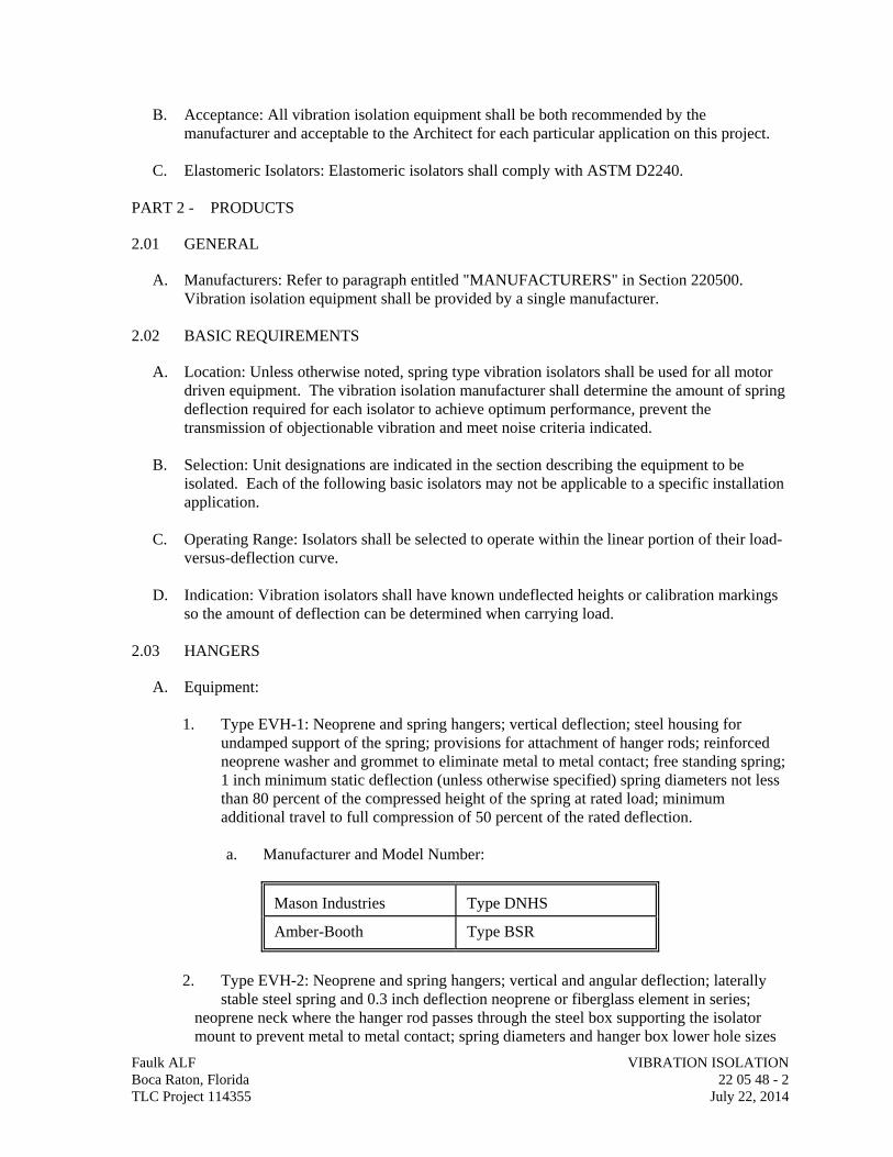
B. Acceptance: All vibration isolation equipment shall be both recommended by the manufacturer and acceptable to the Architect for each particular application on this project.
C. Elastomeric Isolators: Elastomeric isolators shall comply with ASTM D2240.
PART 2 - PRODUCTS
2.01 GENERAL
A. Manufacturers: Refer to paragraph entitled "MANUFACTURERS" in Section 220500. Vibration isolation equipment shall be provided by a single manufacturer.
2.02 BASIC REQUIREMENTS
A. Location: Unless otherwise noted, spring type vibration isolators shall be used for all motor driven equipment. The vibration isolation manufacturer shall determine the amount of spring deflection required for each isolator to achieve optimum performance, prevent the transmission of objectionable vibration and meet noise criteria indicated.
B. Selection: Unit designations are indicated in the section describing the equipment to be
isolated. Each of the following basic isolators may not be applicable to a specific installation application.
C. Operating Range: Isolators shall be selected to operate within the linear portion of their load-
versus-deflection curve. D. Indication: Vibration isolators shall have known undeflected heights or calibration markings
so the amount of deflection can be determined when carrying load. 2.03 HANGERS
A. Equipment:
1. Type EVH-1: Neoprene and spring hangers; vertical deflection; steel housing for undamped support of the spring; provisions for attachment of hanger rods; reinforced neoprene washer and grommet to eliminate metal to metal contact; free standing spring; 1 inch minimum static deflection (unless otherwise specified) spring diameters not less than 80 percent of the compressed height of the spring at rated load; minimum additional travel to full compression of 50 percent of the rated deflection.
a. Manufacturer and Model Number:
Mason Industries Type DNHS Amber-Booth Type BSR
2. Type EVH-2: Neoprene and spring hangers; vertical and angular deflection; laterally
stable steel spring and 0.3 inch deflection neoprene or fiberglass element in series; neoprene neck where the hanger rod passes through the steel box supporting the isolator mount to prevent metal to metal contact; spring diameters and hanger box lower hole sizes
Faulk ALF VIBRATION ISOLATION Boca Raton, Florida 22 05 48 - 2 TLC Project 114355 July 22, 2014
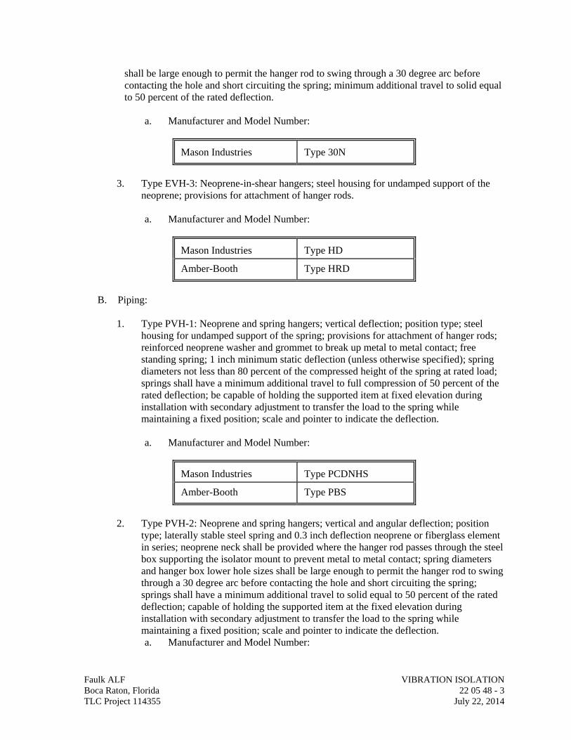
shall be large enough to permit the hanger rod to swing through a 30 degree arc before contacting the hole and short circuiting the spring; minimum additional travel to solid equal to 50 percent of the rated deflection.
a. Manufacturer and Model Number:
Mason Industries Type 30N
3. Type EVH-3: Neoprene-in-shear hangers; steel housing for undamped support of the
neoprene; provisions for attachment of hanger rods.
a. Manufacturer and Model Number:
Mason Industries Type HD Amber-Booth Type HRD
B. Piping:
1. Type PVH-1: Neoprene and spring hangers; vertical deflection; position type; steel
housing for undamped support of the spring; provisions for attachment of hanger rods; reinforced neoprene washer and grommet to break up metal to metal contact; free standing spring; 1 inch minimum static deflection (unless otherwise specified); spring diameters not less than 80 percent of the compressed height of the spring at rated load; springs shall have a minimum additional travel to full compression of 50 percent of the rated deflection; be capable of holding the supported item at fixed elevation during installation with secondary adjustment to transfer the load to the spring while maintaining a fixed position; scale and pointer to indicate the deflection.
a. Manufacturer and Model Number:
Mason Industries Type PCDNHS Amber-Booth Type PBS
2. Type PVH-2: Neoprene and spring hangers; vertical and angular deflection; position
type; laterally stable steel spring and 0.3 inch deflection neoprene or fiberglass element in series; neoprene neck shall be provided where the hanger rod passes through the steel box supporting the isolator mount to prevent metal to metal contact; spring diameters and hanger box lower hole sizes shall be large enough to permit the hanger rod to swing through a 30 degree arc before contacting the hole and short circuiting the spring; springs shall have a minimum additional travel to solid equal to 50 percent of the rated deflection; capable of holding the supported item at the fixed elevation during installation with secondary adjustment to transfer the load to the spring while maintaining a fixed position; scale and pointer to indicate the deflection. a. Manufacturer and Model Number:
Faulk ALF VIBRATION ISOLATION Boca Raton, Florida 22 05 48 - 3 TLC Project 114355 July 22, 2014
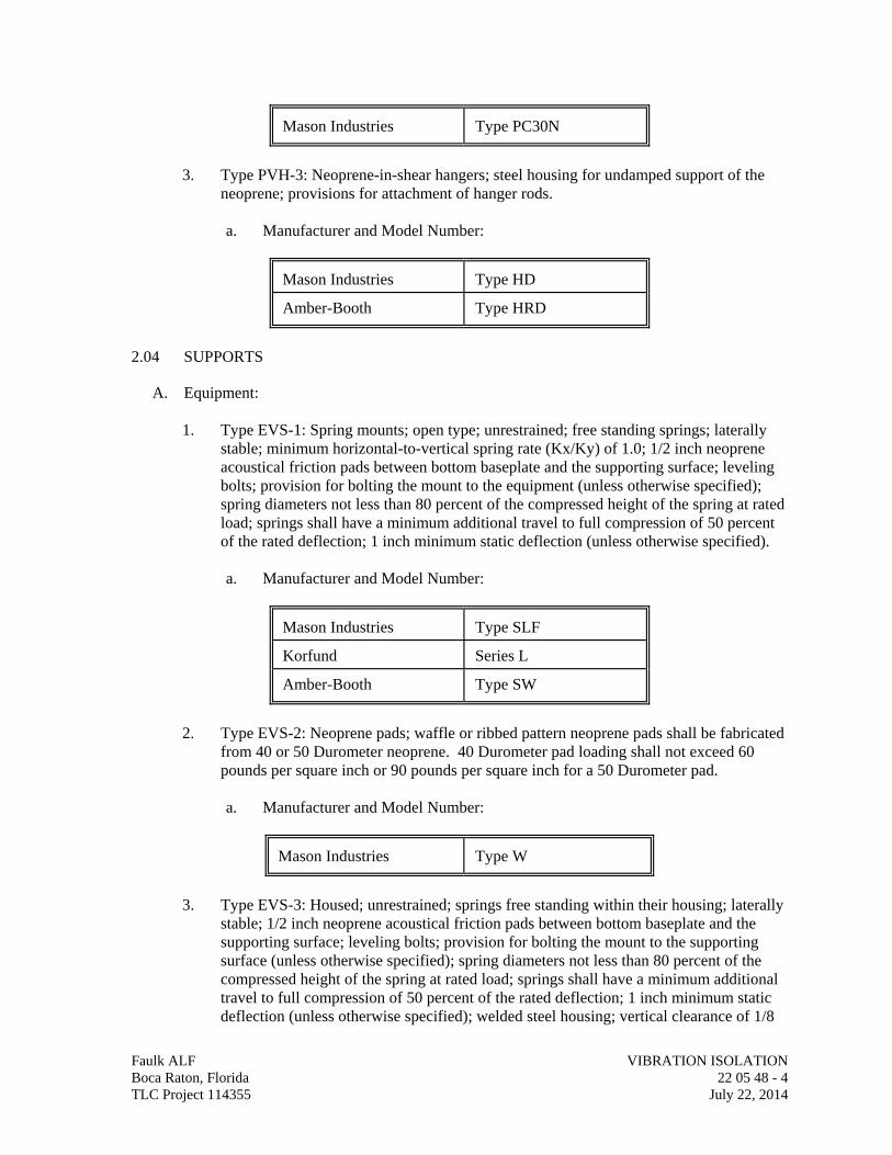
Mason Industries Type PC30N
3. Type PVH-3: Neoprene-in-shear hangers; steel housing for undamped support of the
neoprene; provisions for attachment of hanger rods.
a. Manufacturer and Model Number:
Mason Industries Type HD Amber-Booth Type HRD
2.04 SUPPORTS
A. Equipment:
1. Type EVS-1: Spring mounts; open type; unrestrained; free standing springs; laterally stable; minimum horizontal-to-vertical spring rate (Kx/Ky) of 1.0; 1/2 inch neoprene acoustical friction pads between bottom baseplate and the supporting surface; leveling bolts; provision for bolting the mount to the equipment (unless otherwise specified); spring diameters not less than 80 percent of the compressed height of the spring at rated load; springs shall have a minimum additional travel to full compression of 50 percent of the rated deflection; 1 inch minimum static deflection (unless otherwise specified).
a. Manufacturer and Model Number:
Mason Industries Type SLF Korfund Series L Amber-Booth Type SW
2. Type EVS-2: Neoprene pads; waffle or ribbed pattern neoprene pads shall be fabricated
from 40 or 50 Durometer neoprene. 40 Durometer pad loading shall not exceed 60 pounds per square inch or 90 pounds per square inch for a 50 Durometer pad.
a. Manufacturer and Model Number:
Mason Industries Type W
3. Type EVS-3: Housed; unrestrained; springs free standing within their housing; laterally
stable; 1/2 inch neoprene acoustical friction pads between bottom baseplate and the supporting surface; leveling bolts; provision for bolting the mount to the supporting surface (unless otherwise specified); spring diameters not less than 80 percent of the compressed height of the spring at rated load; springs shall have a minimum additional travel to full compression of 50 percent of the rated deflection; 1 inch minimum static deflection (unless otherwise specified); welded steel housing; vertical clearance of 1/8
Faulk ALF VIBRATION ISOLATION Boca Raton, Florida 22 05 48 - 4 TLC Project 114355 July 22, 2014
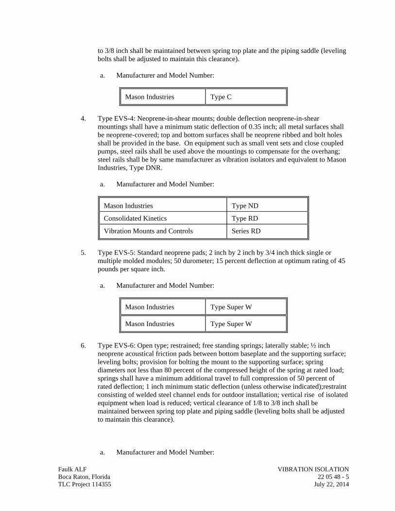
to 3/8 inch shall be maintained between spring top plate and the piping saddle (leveling bolts shall be adjusted to maintain this clearance).
a. Manufacturer and Model Number:
Mason Industries Type C
4. Type EVS-4: Neoprene-in-shear mounts; double deflection neoprene-in-shear
mountings shall have a minimum static deflection of 0.35 inch; all metal surfaces shall be neoprene-covered; top and bottom surfaces shall be neoprene ribbed and bolt holes shall be provided in the base. On equipment such as small vent sets and close coupled pumps, steel rails shall be used above the mountings to compensate for the overhang; steel rails shall be by same manufacturer as vibration isolators and equivalent to Mason Industries, Type DNR.
a. Manufacturer and Model Number:
Mason Industries Type ND Consolidated Kinetics Type RD Vibration Mounts and Controls Series RD
5. Type EVS-5: Standard neoprene pads; 2 inch by 2 inch by 3/4 inch thick single or
multiple molded modules; 50 durometer; 15 percent deflection at optimum rating of 45 pounds per square inch.
a. Manufacturer and Model Number:
Mason Industries Type Super W Mason Industries Type Super W
6. Type EVS-6: Open type; restrained; free standing springs; laterally stable; ½ inch
neoprene acoustical friction pads between bottom baseplate and the supporting surface; leveling bolts; provision for bolting the mount to the supporting surface; spring diameters not less than 80 percent of the compressed height of the spring at rated load; springs shall have a minimum additional travel to full compression of 50 percent of rated deflection; 1 inch minimum static deflection (unless otherwise indicated);restraint consisting of welded steel channel ends for outdoor installation; vertical rise of isolated equipment when load is reduced; vertical clearance of 1/8 to 3/8 inch shall be maintained between spring top plate and piping saddle (leveling bolts shall be adjusted to maintain this clearance). a. Manufacturer and Model Number:
Faulk ALF VIBRATION ISOLATION Boca Raton, Florida 22 05 48 - 5 TLC Project 114355 July 22, 2014
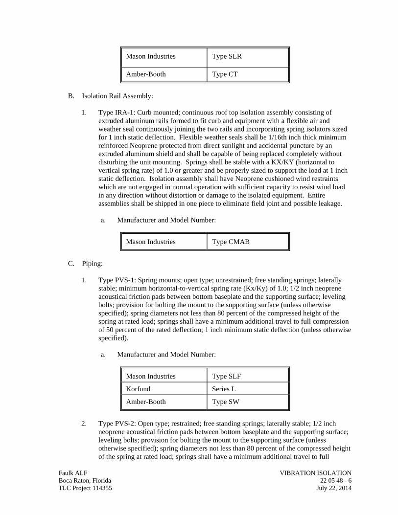
Mason Industries Type SLR Amber-Booth Type CT
B. Isolation Rail Assembly:
1. Type IRA-1: Curb mounted; continuous roof top isolation assembly consisting of
extruded aluminum rails formed to fit curb and equipment with a flexible air and weather seal continuously joining the two rails and incorporating spring isolators sized for 1 inch static deflection. Flexible weather seals shall be 1/16th inch thick minimum reinforced Neoprene protected from direct sunlight and accidental puncture by an extruded aluminum shield and shall be capable of being replaced completely without disturbing the unit mounting. Springs shall be stable with a KX/KY (horizontal to vertical spring rate) of 1.0 or greater and be properly sized to support the load at 1 inch static deflection. Isolation assembly shall have Neoprene cushioned wind restraints which are not engaged in normal operation with sufficient capacity to resist wind load in any direction without distortion or damage to the isolated equipment. Entire assemblies shall be shipped in one piece to eliminate field joint and possible leakage.
a. Manufacturer and Model Number:
Mason Industries Type CMAB
C. Piping:
1. Type PVS-1: Spring mounts; open type; unrestrained; free standing springs; laterally
stable; minimum horizontal-to-vertical spring rate (Kx/Ky) of 1.0; 1/2 inch neoprene acoustical friction pads between bottom baseplate and the supporting surface; leveling bolts; provision for bolting the mount to the supporting surface (unless otherwise specified); spring diameters not less than 80 percent of the compressed height of the spring at rated load; springs shall have a minimum additional travel to full compression of 50 percent of the rated deflection; 1 inch minimum static deflection (unless otherwise specified).
a. Manufacturer and Model Number:
Mason Industries Type SLF Korfund Series L Amber-Booth Type SW
2. Type PVS-2: Open type; restrained; free standing springs; laterally stable; 1/2 inch
neoprene acoustical friction pads between bottom baseplate and the supporting surface; leveling bolts; provision for bolting the mount to the supporting surface (unless otherwise specified); spring diameters not less than 80 percent of the compressed height of the spring at rated load; springs shall have a minimum additional travel to full
Faulk ALF VIBRATION ISOLATION Boca Raton, Florida 22 05 48 - 6 TLC Project 114355 July 22, 2014
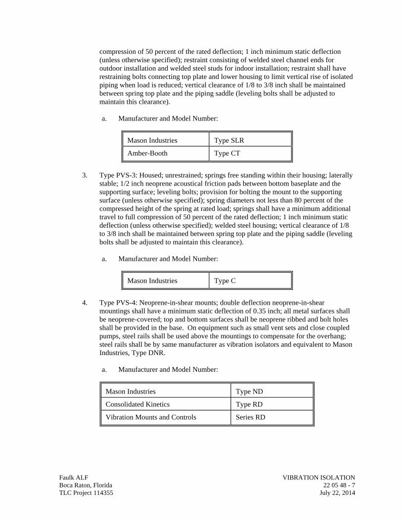
compression of 50 percent of the rated deflection; 1 inch minimum static deflection (unless otherwise specified); restraint consisting of welded steel channel ends for outdoor installation and welded steel studs for indoor installation; restraint shall have restraining bolts connecting top plate and lower housing to limit vertical rise of isolated piping when load is reduced; vertical clearance of 1/8 to 3/8 inch shall be maintained between spring top plate and the piping saddle (leveling bolts shall be adjusted to maintain this clearance).
a. Manufacturer and Model Number:
Mason Industries Type SLR Amber-Booth Type CT
3. Type PVS-3: Housed; unrestrained; springs free standing within their housing; laterally
stable; 1/2 inch neoprene acoustical friction pads between bottom baseplate and the supporting surface; leveling bolts; provision for bolting the mount to the supporting surface (unless otherwise specified); spring diameters not less than 80 percent of the compressed height of the spring at rated load; springs shall have a minimum additional travel to full compression of 50 percent of the rated deflection; 1 inch minimum static deflection (unless otherwise specified); welded steel housing; vertical clearance of 1/8 to 3/8 inch shall be maintained between spring top plate and the piping saddle (leveling bolts shall be adjusted to maintain this clearance).
a. Manufacturer and Model Number:
Mason Industries Type C
4. Type PVS-4: Neoprene-in-shear mounts; double deflection neoprene-in-shear
mountings shall have a minimum static deflection of 0.35 inch; all metal surfaces shall be neoprene-covered; top and bottom surfaces shall be neoprene ribbed and bolt holes shall be provided in the base. On equipment such as small vent sets and close coupled pumps, steel rails shall be used above the mountings to compensate for the overhang; steel rails shall be by same manufacturer as vibration isolators and equivalent to Mason Industries, Type DNR.
a. Manufacturer and Model Number:
Mason Industries Type ND Consolidated Kinetics Type RD Vibration Mounts and Controls Series RD
Faulk ALF VIBRATION ISOLATION Boca Raton, Florida 22 05 48 - 7 TLC Project 114355 July 22, 2014
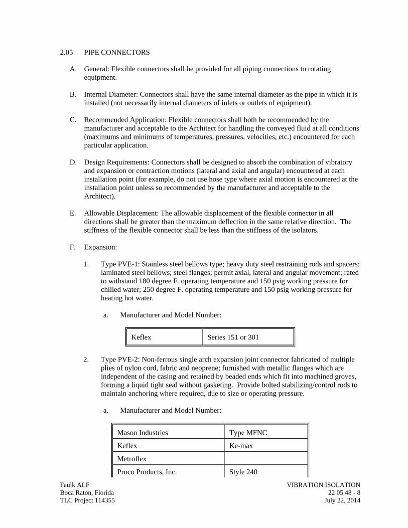
2.05 PIPE CONNECTORS
A. General: Flexible connectors shall be provided for all piping connections to rotating equipment.
B. Internal Diameter: Connectors shall have the same internal diameter as the pipe in which it is
installed (not necessarily internal diameters of inlets or outlets of equipment).
C. Recommended Application: Flexible connectors shall both be recommended by the manufacturer and acceptable to the Architect for handling the conveyed fluid at all conditions (maximums and minimums of temperatures, pressures, velocities, etc.) encountered for each particular application.
D. Design Requirements: Connectors shall be designed to absorb the combination of vibratory
and expansion or contraction motions (lateral and axial and angular) encountered at each installation point (for example, do not use hose type where axial motion is encountered at the installation point unless so recommended by the manufacturer and acceptable to the Architect).
E. Allowable Displacement: The allowable displacement of the flexible connector in all
directions shall be greater than the maximum deflection in the same relative direction. The stiffness of the flexible connector shall be less than the stiffness of the isolators.
F. Expansion:
1. Type PVE-1: Stainless steel bellows type; heavy duty steel restraining rods and spacers;
laminated steel bellows; steel flanges; permit axial, lateral and angular movement; rated to withstand 180 degree F. operating temperature and 150 psig working pressure for chilled water; 250 degree F. operating temperature and 150 psig working pressure for heating hot water.
a. Manufacturer and Model Number:
Keflex Series 151 or 301
2. Type PVE-2: Non-ferrous single arch expansion joint connector fabricated of multiple
plies of nylon cord, fabric and neoprene; furnished with metallic flanges which are independent of the casing and retained by beaded ends which fit into machined groves, forming a liquid tight seal without gasketing. Provide bolted stabilizing/control rods to maintain anchoring where required, due to size or operating pressure. a. Manufacturer and Model Number:
Mason Industries Type MFNC Keflex Ke-max Metroflex Proco Products, Inc. Style 240
Faulk ALF VIBRATION ISOLATION Boca Raton, Florida 22 05 48 - 8 TLC Project 114355 July 22, 2014
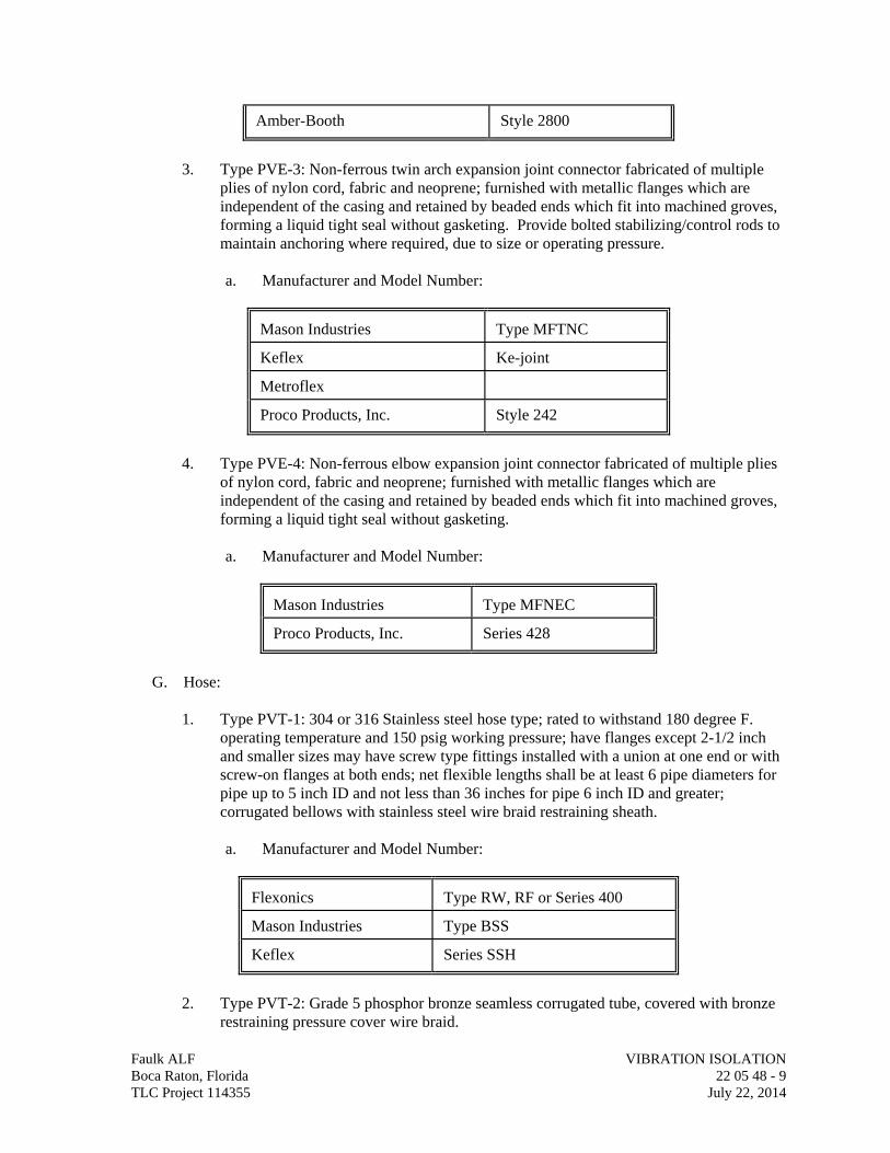
Amber-Booth Style 2800
3. Type PVE-3: Non-ferrous twin arch expansion joint connector fabricated of multiple
plies of nylon cord, fabric and neoprene; furnished with metallic flanges which are independent of the casing and retained by beaded ends which fit into machined groves, forming a liquid tight seal without gasketing. Provide bolted stabilizing/control rods to maintain anchoring where required, due to size or operating pressure.
a. Manufacturer and Model Number:
Mason Industries Type MFTNC Keflex Ke-joint Metroflex Proco Products, Inc. Style 242
4. Type PVE-4: Non-ferrous elbow expansion joint connector fabricated of multiple plies
of nylon cord, fabric and neoprene; furnished with metallic flanges which are independent of the casing and retained by beaded ends which fit into machined groves, forming a liquid tight seal without gasketing.
a. Manufacturer and Model Number:
Mason Industries Type MFNEC Proco Products, Inc. Series 428
G. Hose:
1. Type PVT-1: 304 or 316 Stainless steel hose type; rated to withstand 180 degree F.
operating temperature and 150 psig working pressure; have flanges except 2-1/2 inch and smaller sizes may have screw type fittings installed with a union at one end or with screw-on flanges at both ends; net flexible lengths shall be at least 6 pipe diameters for pipe up to 5 inch ID and not less than 36 inches for pipe 6 inch ID and greater; corrugated bellows with stainless steel wire braid restraining sheath.
a. Manufacturer and Model Number:
Flexonics Type RW, RF or Series 400 Mason Industries Type BSS Keflex Series SSH
2. Type PVT-2: Grade 5 phosphor bronze seamless corrugated tube, covered with bronze
restraining pressure cover wire braid.
Faulk ALF VIBRATION ISOLATION Boca Raton, Florida 22 05 48 - 9 TLC Project 114355 July 22, 2014
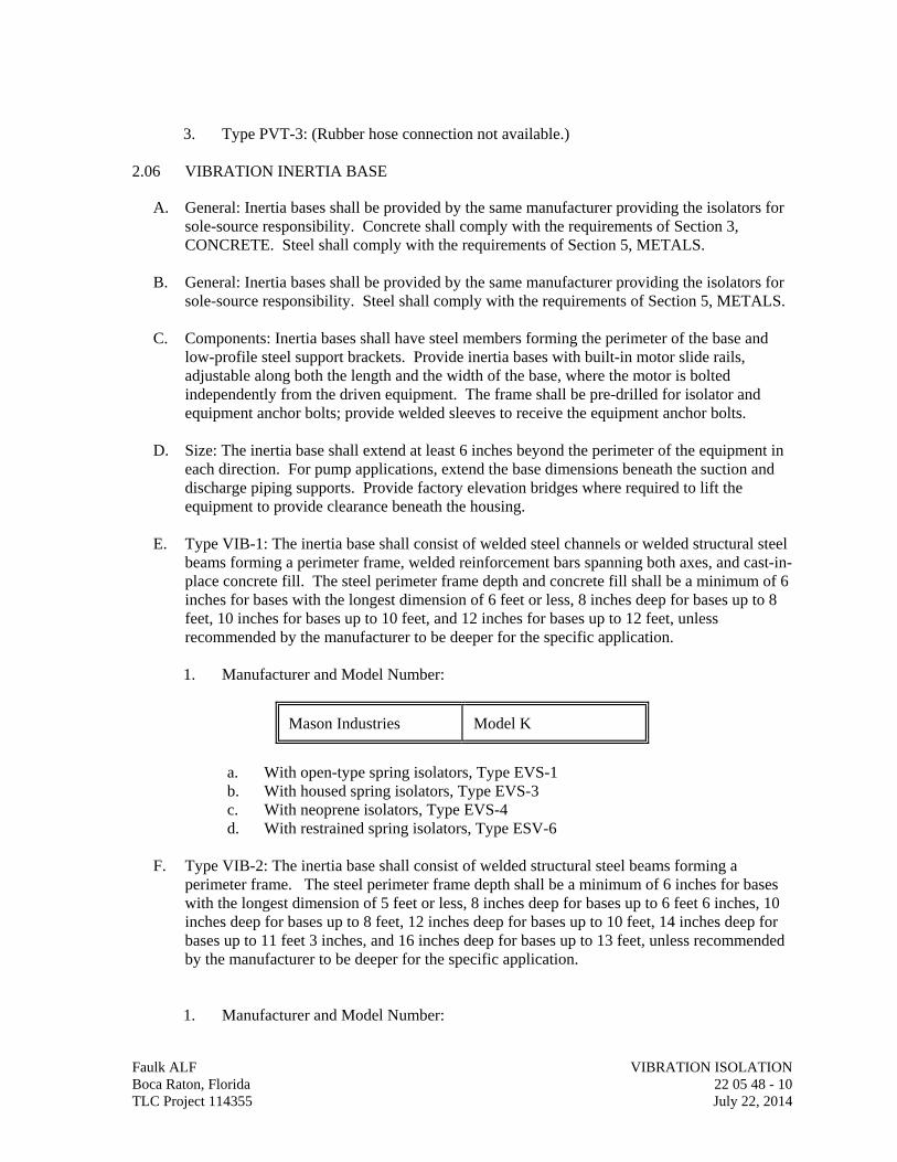
3. Type PVT-3: (Rubber hose connection not available.)
2.06 VIBRATION INERTIA BASE
A. General: Inertia bases shall be provided by the same manufacturer providing the isolators for sole-source responsibility. Concrete shall comply with the requirements of Section 3, CONCRETE. Steel shall comply with the requirements of Section 5, METALS.
B. General: Inertia bases shall be provided by the same manufacturer providing the isolators for
sole-source responsibility. Steel shall comply with the requirements of Section 5, METALS.
C. Components: Inertia bases shall have steel members forming the perimeter of the base and low-profile steel support brackets. Provide inertia bases with built-in motor slide rails, adjustable along both the length and the width of the base, where the motor is bolted independently from the driven equipment. The frame shall be pre-drilled for isolator and equipment anchor bolts; provide welded sleeves to receive the equipment anchor bolts.
D. Size: The inertia base shall extend at least 6 inches beyond the perimeter of the equipment in
each direction. For pump applications, extend the base dimensions beneath the suction and discharge piping supports. Provide factory elevation bridges where required to lift the equipment to provide clearance beneath the housing.
E. Type VIB-1: The inertia base shall consist of welded steel channels or welded structural steel
beams forming a perimeter frame, welded reinforcement bars spanning both axes, and cast-in-place concrete fill. The steel perimeter frame depth and concrete fill shall be a minimum of 6 inches for bases with the longest dimension of 6 feet or less, 8 inches deep for bases up to 8 feet, 10 inches for bases up to 10 feet, and 12 inches for bases up to 12 feet, unless recommended by the manufacturer to be deeper for the specific application.
1. Manufacturer and Model Number:
Mason Industries Model K
a. With open-type spring isolators, Type EVS-1 b. With housed spring isolators, Type EVS-3 c. With neoprene isolators, Type EVS-4 d. With restrained spring isolators, Type ESV-6
F. Type VIB-2: The inertia base shall consist of welded structural steel beams forming a
perimeter frame. The steel perimeter frame depth shall be a minimum of 6 inches for bases with the longest dimension of 5 feet or less, 8 inches deep for bases up to 6 feet 6 inches, 10 inches deep for bases up to 8 feet, 12 inches deep for bases up to 10 feet, 14 inches deep for bases up to 11 feet 3 inches, and 16 inches deep for bases up to 13 feet, unless recommended by the manufacturer to be deeper for the specific application.
1. Manufacturer and Model Number:
Faulk ALF VIBRATION ISOLATION Boca Raton, Florida 22 05 48 - 10 TLC Project 114355 July 22, 2014
Mason Industries Model WF
a. With open-type spring isolators, Type EVS-1 b. With housed spring isolators, Type EVS-3 c. With neoprene isolators, Type EVS-4 d. With restrained spring isolators, Type EVS-6
G. Type VIB-3: The inertia base shall consist of bolted steel channels or bolted structural steel
beams forming a perimeter frame, welded reinforcement bars spanning both axes, and cast-in-place concrete fill, unless otherwise indicated. The steel perimeter frame depth and concrete fill depth shall be a minimum of 6 inches for bases with the longest dimension of 6 feet or less, or 10 inches for bases up to 12 feet, unless recommended by the manufacturer to be deeper for the specific application.
1. Manufacturer and Model Number:
Mason Industries Model BMK
a. With open-type spring isolators, Type EVS-1 b. With housed spring isolators, Type EVS-3 c. With neoprene isolators, Type EVS-4 d. With restrained spring isolators, Type EVS-6
2.07 STRUCTURAL FRAME
A. Type SVF-1: Floor mounted structural steel rail or beam equipment base; designed and supplied by the isolator manufacturer; steel channels welded together to provide full strength of the beams and a rigid base; minimum depth of 1/12th of the longest span between isolators, but not less than 6 inches; longest span shall not be greater than 14 feet; welded steel isolator brackets shall be provided to reduce the mounting height of the equipment.
B. Type SVF-2: Suspended structural steel angle frame for suspended equipment where a
continuous or common frame is not inherent to the unit; constructed of steel angles welded together running the entire perimeter of the unit; steel angle brackets shall be welded to the frame at isolator locations; provide hole for attaching isolator; install 1/4 inch neoprene gasket between the frame and equipment contact area; equipment shall be securely bolted to the frame.
2.08 ACOUSTIC SEALS
A. Type AVS-1: S-shaped molded synthetic rubber seal attached with stainless steel clamps to the pipe wall sleeves and to carrier piping. Wall sleeves shall be two pipe sizes larger than the carrier pipe and its insulation.
1. Manufacturer and Model Number:
Faulk ALF VIBRATION ISOLATION Boca Raton, Florida 22 05 48 - 11 TLC Project 114355 July 22, 2014
Amber-Booth Type 301
PART 3 - EXECUTION
3.01 GENERAL
A. Installation: Isolators shall be installed in strict accordance with the manufacturer's instructions and shall be adjusted prior to requesting final inspection or the performance of any vibration testing specified. If, in the opinion of the Architect, objectionable noise or vibration is produced or transmitted, necessary changes or additions shall be performed to eliminate the noise and vibration without additional cost to the Owner.
B. Corrosion Protection: Steel components shall be phosphated and painted. All nuts, bolts and
washers shall be zinc-electroplated. Structural steel bases shall be thoroughly cleaned of welding slag and primed with zinc-chromate or metal etching primer.
C. Weather Protection: All isolators exposed to weather shall have steel parts PVC coated,
neoprene coated or hot-dip galvanized. Aluminum components shall be etched and painted. Nuts, bolts and washers shall be zinc-electroplated.
D. Positioning: Each item of equipment (machinery, piping, etc.) which is required to have
vibration isolation equipment shall rest in its intended, operating position (i.e.; exactly level, etc.) after installation of vibration isolation equipment. Acceptance of such vibration isolation equipment by the Architect shall not constitute a waiver of this responsibility.
E. Pads: Rotating or vibrating equipment which is specified to rest on concrete housekeeping
pads shall have minimum 5/16 inch thick Type EVS-2 isolation pads unless otherwise indicated. Loading shall not exceed manufacturer's recommended rating.
F. Cleaning: Prior to start-up, clean out all foreign matter between isolators or bases and
equipment and verify there are no isolation short-circuits in the installation. 3.02 PIPING IN MECHANICAL EQUIPMENT AND AIR HANDLING UNIT ROOMS
A. General:
1. Isolators for equipment and piping are described elsewhere in this division. The vibration isolation manufacturer shall coordinate the selection of piping supports with equipment supports to provide a carefully engineered system designed to accommodate expansion and contraction without excessive stress or misalignment at equipment connections or in the piping.
2. Temporary anchors, where required, shall be installed to permit pre-adjustment of springs in risers.
3. Permanent limit stops shall be installed to prevent excessive vertical motion of risers in the event water is drained from system. Locations and other details of these limit stops shall be submitted to the Architect for acceptance.
4. Piping connected to vibration isolated equipment shall not strain or force out of alignment the vibration isolators supporting the basic equipment, nor shall pipes restrict such equipment from "floating" freely on its respective vibration isolation system.
Faulk ALF VIBRATION ISOLATION Boca Raton, Florida 22 05 48 - 12 TLC Project 114355 July 22, 2014
Faulk ALF VIBRATION ISOLATION Boca Raton, Florida 22 05 48 - 13 TLC Project 114355 July 22, 2014
5. Piping connected to vibrating equipment shall not physically contact any building construction or non-isolated systems or components.
6. The weight of the pipe shall not be carried by walls through which the pipe passes.
B. Isolator Locations: 1. Acoustic Seals: Provide Type AVS-1 acoustic seals at all wall, ceiling and floor
openings through which pipe runs from equipment rooms into adjoining occupied spaces.
2. Hanger Boxes: Isolators shall be installed with the hanger box attached to or hung as close as possible to the structure. Hanger rods shall be aligned to clear the hanger box.
3.03 EQUIPMENT ISOLATION
A. Structural Steel Base: Equipment on structural steel bases shall be placed in position and supported temporarily by blocks or shims prior to the installation of the equipment or isolators. Isolators shall be installed without raising the equipment or frame assembly, and shall not cause any stress or misalignment. After installation is complete and under full operational load, the isolators shall be adjusted to transfer the load from the blocks to the isolators. When all isolators are properly adjusted, the blocks or shims shall be barely free and shall be removed. Verify that all isolators and mounting systems permit equipment motion in all directions but flexibly limit motion to 1/4 inch.
B. Inertia Base: Equipment on inertia bases shall be placed in position and supported
temporarily by blocks or shims prior to the installation of the equipment or isolators. Isolators shall be installed without raising the equipment or frame assembly, and shall not cause any piping stress or misalignment. After installation is complete and under full operational load, the isolators shall be adjusted to transfer the load from the blocks to the isolators. When all isolators are properly adjusted, the blocks or shims shall be barely free and shall be removed. Verify that all isolators and mounting systems permit equipment motion in all directions but flexibly limit motion to 1/4 inch.
C. Vibration Measurement: No vibration amplitude measurement at driving (motor) or driven
(pump, fan, etc.) speeds shall exceed manufacturers recommended values. No axial vibration shall exceed maximum radial (perpendicular to shaft) vibration at any bearing or measuring location. In no event shall any rotating equipment exceed 0.05 inches/second rms vibration amplitude under normal operating conditions. Whenever rotational speed is measured as the disturbing frequency, the lowest speed in the system shall be used.
3.04 MANUFACTURER'S CHECKOUT
A. Certification: The vibration isolation manufacturer shall provide supervision necessary to assure correct installation and adjustment of the isolators. Upon completion of the installation and after system the is put into operation, the manufacturer shall make a final inspection and submit a report to the Architect in writing certifying the installation is in compliance with the manufacturer's recommendations and the requirements of these specifications.
END OF SECTION 22 05 48
SECTION 22 05 53
IDENTIFICATION FOR PLUMBING PIPING & EQUIPMENT
Faulk ALF IDENTIFICATION FOR PLUMBING PIPING & EQUIPMENT Boca Raton, Florida 22 05 53 - 1 TLC Project 114355 July 22, 2014
PART 1 - GENERAL
1.01 RELATED DOCUMENTS
A. Drawings and general provisions of the Contract, including General and Supplementary Conditions and Division 01 Specification Sections, apply to this Section.
1.02 SUMMARY
A. Section Includes:
1. Equipment labels. 2. Pipe labels. 3. Valve tags.
1.03 ACTION SUBMITTALS
A. Product Data: For each type of product indicated.
1.04 COORDINATION
A. Coordinate installation of identifying devices with completion of covering and painting of surfaces where devices are to be applied.
B. Coordinate installation of identifying devices with locations of access panels and doors.
C. Install identifying devices before installing acoustical ceilings and similar concealment.
PART 2 - PRODUCTS
2.01 EQUIPMENT LABELS
A. Plastic Labels for Equipment:
1. Material and Thickness: Multilayer, multicolor, plastic labels for mechanical engraving, 1/8 inch thick, and having predrilled holes for attachment hardware.
2. Letter Color: White. 3. Background Color: Black. 4. Maximum Temperature: Able to withstand temperatures up to 160 deg F. 5. Minimum Label Size: Length and width vary for required label content, but not less
than 2-1/2 by 3/4 inch. 6. Minimum Letter Size: 1/4 inchfor name of units if viewing distance is less than 24
inches, 1/2 inchfor viewing distances up to 72 inches, and proportionately larger lettering for greater viewing distances. Include secondary lettering two-thirds to three-fourths the size of principal lettering.
7. Fasteners: Stainless-steel rivets or self-tapping screws. 8. Adhesive: Contact-type permanent adhesive, compatible with label and with
substrate.
B. Label Content: Include equipment's Drawing designation or unique equipment number, Drawing numbers where equipment is indicated (plans, details, and schedules), plus the Specification Section number and title where equipment is specified.
C. Equipment Label Schedule: For each item of equipment to be labeled, on 8-1/2-by-11-inch bond paper. Tabulate equipment identification number and identify Drawing numbers where equipment is indicated (plans, details, and schedules), plus the Specification Section number and title where equipment is specified. Equipment schedule shall be included in operation and maintenance data.
2.02 PIPE LABELS
A. General Requirements for Manufactured Pipe Labels: Preprinted, color-coded, with lettering indicating service, and showing flow direction.
B. Pretensioned Pipe Labels: Precoiled, semirigid plastic formed to partially cover circumference of pipe and to attach to pipe without fasteners or adhesive.
C. Pipe Label Contents: Include identification of piping service using same designations or abbreviations as used on Drawings and an arrow indicating flow direction.
1. Flow-Direction Arrows: Integral with piping system service lettering to accommodate both directions, or as separate unit on each pipe label to indicate flow direction.
2. Lettering Size: At least 1-1/2 incheshigh.
2.03 VALVE TAGS
A. Valve Tags: Stamped or engraved with 1/4-inch letters for piping system abbreviation and 1/2-inch numbers.
1. Tag Material: Brass, 0.032-inch or Stainless steel, 0.025-inch minimum thickness, and having predrilled or stamped holes for attachment hardware.
2. Fasteners: Brass wire-link or beaded chain or S-hook.
B. Valve Schedules: For each piping system, on 8-1/2-by-11-inchbond paper. Tabulate valve number, piping system, system abbreviation (as shown on valve tag), location of valve (room or space), normal-operating position (open, closed, or modulating), and variations for identification. Mark valves for emergency shutoff and similar special uses.
1. Valve-tag schedule shall be included in operation and maintenance data.
PART 3 - EXECUTION
3.01 PREPARATION
A. Clean piping and equipment surfaces of substances that could impair bond of identification devices, including dirt, oil, grease, release agents, and incompatible primers, paints, and encapsulants.
Faulk ALF IDENTIFICATION FOR PLUMBING PIPING & EQUIPMENT Boca Raton, Florida 22 05 53 - 2 TLC Project 114355 July 22, 2014
Faulk ALF IDENTIFICATION FOR PLUMBING PIPING & EQUIPMENT Boca Raton, Florida 22 05 53 - 3 TLC Project 114355 July 22, 2014
3.02 EQUIPMENT LABEL INSTALLATION
A. Install or permanently fasten labels on each major item of mechanical equipment.
B. Locate equipment labels where accessible and visible.
3.03 PIPE LABEL INSTALLATION
A. Locate pipe labels where piping is exposed or above accessible ceilings in finished spaces; machine rooms; accessible maintenance spaces such as shafts, tunnels, and plenums; and exterior exposed locations as follows:
1. Near each valve and control device. 2. Near each branch connection, excluding short takeoffs for fixtures and terminal units.
Where flow pattern is not obvious, mark each pipe at branch. 3. Near penetrations through walls, floors, ceilings, and inaccessible enclosures. 4. At access doors, manholes, and similar access points that permit view of concealed
piping. 5. Near major equipment items and other points of origination and termination. 6. Spaced at maximum intervals of 25 feet along each run. Reduce intervals to 10 feet
in areas of congested piping and equipment.
7. Identification of potable and non-potable water.
a. In all buildings where two or more water distribution system, one potable water and the other non-potable water, ate installed, each system shall be identified either by color marking or metal tags as required by ASME A13.1. Reclaimed water systems shall be identified using color coded Pantone Purple 522C and marked with the statement “NONPOTABLE WATER - NOT FOR HUMAN CONSUMPTION.
B. Pipe Label Color: Refer to ASME (ANSI) Standard A13.1-2007.
3.04 VALVE-TAG INSTALLATION
A. Install tags on valves and control devices in piping systems, except check valves; valves within factory-fabricated equipment units; shutoff valves; faucets; convenience and lawn-watering hose connections; and similar roughing-in connections of end-use fixtures and units. List tagged valves in a valve schedule.
B. Valve-Tag Application Schedule: Tag valves according to size, shape, and color scheme and with captions similar to those indicated in the following subparagraphs:
1. Valve-Tag Size and Shape:
a. Cold Water: 2 inches, round. b. Hot Water: 2 inches, round. c. Low-Pressure Compressed Air: 2 inches, round.
END OF SECTION 22 05 53
SECTION 22 07 19 PLUMBING PIPING INSULATION
Faulk ALF PLUMBING PIPING INSULATION Boca Raton, Florida 22 07 19 - 1 TLC Project 114355 July 22, 2014
PART 1 - GENERAL
1.01 RELATED DOCUMENTS
A. Drawings and general provisions of the Contract, including General and Supplementary Conditions and Division 01 Specification Sections, apply to this Section.
1.02 SUMMARY
A. Section Includes:
1. Insulation Materials:
a. Flexible elastomeric. b. Mineral fiber.
2. Insulating cements. 3. Adhesives. 4. Mastics. 5. Lagging adhesives. 6. Sealants. 7. Factory-applied jackets. 8. Tapes. 9. Corner angles.
1.03 SUBMITTALS
A. Product Data: For each type of product indicated. Include thermal conductivity, thickness, and jackets (both factory and field applied, if any).
B. Submittal:
1. For adhesives and sealants, including printed statement of VOC content compliant with South Coast Air Quality Management District (SCAQMD) Rule #1168.
1.04 QUALITY ASSURANCE
A. Installer Qualifications: Skilled mechanics who have successfully completed an apprenticeship program or another craft training program certified by the Department of Labor, Bureau of Apprenticeship and Training.
B. Fire-Test-Response Characteristics: Insulation and related materials shall have fire-test-response characteristics indicated, as determined by testing identical products per ASTM E 84, by a testing and inspecting agency acceptable to authorities having jurisdiction. Factory label insulation and jacket materials and adhesive, mastic, tapes, and cement material containers, with appropriate markings of applicable testing and inspecting agency. 1. Insulation Installed Indoors: Flame-spread index of 25 or less, and smoke-developed
index of 50 or less.
2. Insulation Installed Outdoors: Flame-spread index of 75 or less, and smoke-developed index of 150 or less.
1.05 DELIVERY, STORAGE, AND HANDLING
A. Packaging: Insulation material containers shall be marked by manufacturer with appropriate ASTM standard designation, type and grade, and maximum use temperature.
1.06 COORDINATION
A. Coordinate size and location of supports, hangers, and insulation shields specified in Division 22 Section "Hangers and Supports for Plumbing Piping and Equipment."
B. Coordinate clearance requirements with piping Installer for piping insulation application and equipment Installer for equipment insulation application. Before preparing piping Shop Drawings establish and maintain clearance requirements for installation of insulation and field-applied jackets and finishes and for space required for maintenance.
C. Coordinate installation and testing of heat tracing.
1.07 SCHEDULING
A. Schedule insulation application after pressure testing systems and, where required, after installing and testing heat tracing. Insulation application may begin on segments that have satisfactory test results.
B. Complete installation and concealment of plastic materials as rapidly as possible in each area of construction.
PART 2 - PRODUCTS
2.01 INSULATION MATERIALS
A. Comply with requirements in Part 3 schedule articles for where insulating materials shall be applied.
B. Products shall not contain asbestos, lead, mercury, or mercury compounds.
C. Products that come in contact with stainless steel shall have a leachable chloride content of less than 50 ppm when tested according to ASTM C 871.
D. Insulation materials for use on austenitic stainless steel shall be qualified as acceptable according to ASTM C 795.
E. Flexible Elastomeric: Closed-cell, sponge- or expanded-rubber materials. Comply with ASTM C 534, Type I for tubular materials and Type II for sheet materials.
1. Products: Subject to compliance with requirements, provide one of the following:
a. Aeroflex USA Inc.; Aerocel. b. Armacell LLC; AP Armaflex. c. RBX Corporation; Insul-Sheet 1800 and Insul-Tube 180.
Faulk ALF PLUMBING PIPING INSULATION Boca Raton, Florida 22 07 19 - 2 TLC Project 114355 July 22, 2014
F. Mineral-Fiber, Preformed Pipe Insulation:
1. Products: Subject to compliance with requirements, provide one of the following:
a. Fibrex Insulations Inc.; Coreplus 1200. b. Johns Manville; Micro-Lok. c. Knauf Insulation; 1000(Pipe Insulation. d. Manson Insulation Inc.; Alley-K. e. Owens Corning; Fiberglas Pipe Insulation.
2. Type I, 850 deg F Materials: Mineral or glass fibers bonded with a thermosetting resin. Comply with ASTM C 547, Type I, Grade A, with factory-applied ASJ-SSL. Factory-applied jacket requirements are specified in "Factory-Applied Jackets" Article.
2.02 INSULATING CEMENTS
A. Mineral-Fiber Insulating Cement: Comply with ASTM C 195.
1. Products: Subject to compliance with requirements, provide one of the following:
a. Insulco, Division of MFS, Inc.; Triple I. b. P. K. Insulation Mfg. Co., Inc.; Super-Stik.
2.03 ADHESIVES
A. Materials shall be compatible with insulation materials, jackets, and substrates and for bonding insulation to itself and to surfaces to be insulated, unless otherwise indicated.
B. Flexible Elastomeric Adhesive: Comply with MIL-A-24179A, Type II, Class I.
1. Products: Subject to compliance with requirements, provide one of the following:
a. Aeroflex USA Inc.; Aeroseal. b. Armacell LCC; 520 Adhesive. c. RBX Corporation; Rubatex Contact Adhesive.
C. Mineral-Fiber Adhesive: Comply with MIL-A-3316C, Class 2, Grade A.
1. Products: Subject to compliance with requirements, provide one of the following:
a. Childers Products, Division of ITW; CP-82. b. Foster Products Corporation, H. B. Fuller Company; 85-20. c. ITW TACC, Division of Illinois Tool Works; S-90/80. d. Marathon Industries, Inc.; 225. e. Mon-Eco Industries, Inc.; 22-25.
D. ASJ Adhesive, and FSK and PVDC Jacket Adhesive: Comply with MIL-A-3316C, Class 2, Grade A for bonding insulation jacket lap seams and joints.
Faulk ALF PLUMBING PIPING INSULATION Boca Raton, Florida 22 07 19 - 3 TLC Project 114355 July 22, 2014
1. Products: Subject to compliance with requirements, provide one of the following:
a. Childers Products, Division of ITW; CP-82. b. Foster Products Corporation, H. B. Fuller Company; 85-20. c. ITW TACC, Division of Illinois Tool Works; S-90/80. d. Marathon Industries, Inc.; 225. e. Mon-Eco Industries, Inc.; 22-25.
2.04 MASTICS
A. Materials shall be compatible with insulation materials, jackets, and substrates; comply with MIL-C-19565C, Type II.
B. Vapor-Barrier Mastic: Water based; suitable for indoor and outdoor use on below ambient services.
1. Products: Subject to compliance with requirements, provide one of the following:
a. Childers Products, Division of ITW; CP-35. b. Foster Products Corporation, H. B. Fuller Company; 30-90. c. ITW TACC, Division of Illinois Tool Works; CB-50. d. Marathon Industries, Inc.; 590. e. Mon-Eco Industries, Inc.; 55-40. f. Vimasco Corporation; 749.
2. Water-Vapor Permeance: ASTM E 96, Procedure B, 0.013 perm at 43-mil dry film thickness.
3. Service Temperature Range: Minus 20 to plus 180 deg F. 4. Solids Content: ASTM D 1644, 59 percent by volume and 71 percent by weight. 5. Color: White.
2.05 LAGGING ADHESIVES
A. Description: Comply with MIL-A-3316C Class I, Grade A and shall be compatible with insulation materials, jackets, and substrates.
1. Products: Subject to compliance with requirements, provide one of the following:
a. Childers Products, Division of ITW; CP-52. b. Foster Products Corporation, H. B. Fuller Company; 81-42. c. Marathon Industries, Inc.; 130. d. Mon-Eco Industries, Inc.; 11-30. e. Vimasco Corporation; 136.
2. Fire-resistant, water-based lagging adhesive and coating for use indoors to adhere fire-resistant lagging cloths over equipment and pipe insulation.
3. Service Temperature Range: Minus 50 to plus 180 deg F.
4. Color: White.
Faulk ALF PLUMBING PIPING INSULATION Boca Raton, Florida 22 07 19 - 4 TLC Project 114355 July 22, 2014
2.06 SEALANTS
A. Joint Sealants:
1. Materials shall be compatible with insulation materials, jackets, and substrates. 2. Permanently flexible, elastomeric sealant. 3. Service Temperature Range: Minus 100 to plus 300 deg F. 4. Color: White or gray.
B. ASJ Flashing Sealants, and Vinyl, PVDC, and PVC Jacket Flashing Sealants:
1. Products: Subject to compliance with requirements, provide one of the following:
a. Childers Products, Division of ITW; CP-76.
2. Materials shall be compatible with insulation materials, jackets, and substrates. 3. Fire- and water-resistant, flexible, elastomeric sealant. 4. Service Temperature Range: Minus 40 to plus 250 deg F. 5. Color: White.
2.07 FACTORY-APPLIED JACKETS
A. Insulation system schedules indicate factory-applied jackets on various applications. When factory-applied jackets are indicated, comply with the following:
1. ASJ: White, kraft-paper, fiberglass-reinforced scrim with aluminum-foil backing; complying with ASTM C 1136, Type I.
2.08 TAPES
A. ASJ Tape: White vapor-retarder tape matching factory-applied jacket with acrylic adhesive, complying with ASTM C 1136.
1. Products: Subject to compliance with requirements, provide one of the following:
a. Avery Dennison Corporation, Specialty Tapes Division; Fasson 0835. b. Compac Corp.; 104 and 105. c. Ideal Tape Co., Inc., an American Biltrite Company; 428 AWF ASJ. d. Venture Tape; 1540 CW Plus, 1542 CW Plus, and 1542 CW Plus/SQ.
2. Width: 3 inches. 3. Thickness: 11.5 mils. 4. Adhesion: 90 ounces force/inch in width. 5. Elongation: 2 percent. 6. Tensile Strength: 40 lbf/inch in width. 7. ASJ Tape Disks and Squares: Precut disks or squares of ASJ tape.
2.09 CORNER ANGLES
A. PVC Corner Angles: 30 mils thick, minimum 1 by 1 inch, PVC according to ASTM D 1784, Class 16354-C. White or color-coded to match adjacent surface.
Faulk ALF PLUMBING PIPING INSULATION Boca Raton, Florida 22 07 19 - 5 TLC Project 114355 July 22, 2014
PART 3 - EXECUTION
3.01 EXAMINATION
A. Examine substrates and conditions for compliance with requirements for installation and other conditions affecting performance of insulation application.
1. Verify that systems and equipment to be insulated have been tested and are free of defects.
2. Verify that surfaces to be insulated are clean and dry. 3. Proceed with installation only after unsatisfactory conditions have been corrected.
3.02 PREPARATION
A. Surface Preparation: Clean and dry surfaces to receive insulation. Remove materials that will adversely affect insulation application.
B. Surface Preparation: Clean and prepare surfaces to be insulated. Before insulating, apply a corrosion coating to insulated surfaces as follows:
1. Stainless Steel: Coat 300 series stainless steel with an epoxy primer 5 mils thick and an epoxy finish 5 mils thick if operating in a temperature range between 140 and 300 deg F. Consult coating manufacturer for appropriate coating materials and application methods for operating temperature range.
2. Carbon Steel: Coat carbon steel operating at a service temperature between 32 and 300 deg F with an epoxy coating. Consult coating manufacturer for appropriate coating materials and application methods for operating temperature range.
C. Coordinate insulation installation with the trade installing heat tracing. Comply with requirements for heat tracing that apply to insulation.
D. Mix insulating cements with clean potable water; if insulating cements are to be in contact with stainless-steel surfaces, use demineralized water.
3.03 GENERAL INSTALLATION REQUIREMENTS
A. Install insulation materials, accessories, and finishes with smooth, straight, and even surfaces; free of voids throughout the length of equipment and piping including fittings, valves, and specialties.
B. Install insulation materials, forms, vapor barriers or retarders, jackets, and thicknesses required for each item of equipment and pipe system as specified in insulation system schedules.
C. Install accessories compatible with insulation materials and suitable for the service. Install accessories that do not corrode, soften, or otherwise attack insulation or jacket in either wet or dry state.
D. Install insulation with longitudinal seams at top and bottom of horizontal runs.
E. Install multiple layers of insulation with longitudinal and end seams staggered.
Faulk ALF PLUMBING PIPING INSULATION Boca Raton, Florida 22 07 19 - 6 TLC Project 114355 July 22, 2014
F. Do not weld brackets, clips, or other attachment devices to piping, fittings, and specialties.
G. Keep insulation materials dry during application and finishing.
H. Install insulation with tight longitudinal seams and end joints. Bond seams and joints with adhesive recommended by insulation material manufacturer.
I. Install insulation with least number of joints practical.
J. Where vapor barrier is indicated, seal joints, seams, and penetrations in insulation at hangers, supports, anchors, and other projections with vapor-barrier mastic.
1. Install insulation continuously through hangers and around anchor attachments. 2. For insulation application where vapor barriers are indicated, extend insulation on
anchor legs from point of attachment to supported item to point of attachment to structure. Taper and seal ends at attachment to structure with vapor-barrier mastic.
3. Install insert materials and install insulation to tightly join the insert. Seal insulation to insulation inserts with adhesive or sealing compound recommended by insulation material manufacturer.
4. Cover inserts with jacket material matching adjacent pipe insulation. Install shields over jacket, arranged to protect jacket from tear or puncture by hanger, support, and shield.
K. Apply adhesives, mastics, and sealants at manufacturer's recommended coverage rate and wet and dry film thicknesses.
L. Install insulation with factory-applied jackets as follows:
1. Draw jacket tight and smooth. 2. Cover joints and seams with tape as recommended by insulation material
manufacturer to maintain vapor seal. 3. Where vapor barriers are indicated, apply vapor-barrier mastic on seams and joints
and at ends adjacent to pipe flanges and fittings.
M. Cut insulation in a manner to avoid compressing insulation more than 75 percent of its nominal thickness.
N. Finish installation with systems at operating conditions. Repair joint separations and cracking due to thermal movement.
O. Repair damaged insulation facings by applying same facing material over damaged areas. Extend patches at least 4 inches beyond damaged areas. Adhere and seal patches similar to butt joints.
P. For above ambient services, do not install insulation to the following: 1. Vibration-control devices. 2. Testing agency labels and stamps. 3. Nameplates and data plates. 4. Manholes. 5. Handholes. 6. Cleanouts.
Faulk ALF PLUMBING PIPING INSULATION Boca Raton, Florida 22 07 19 - 7 TLC Project 114355 July 22, 2014
3.04 PENETRATIONS
A. Insulation Installation at Aboveground Exterior Wall Penetrations: Install insulation continuously through wall penetrations.
1. Seal penetrations with flashing sealant. 2. For applications requiring only indoor insulation, terminate insulation inside wall
surface and seal with joint sealant. For applications requiring indoor and outdoor insulation, install insulation for outdoor applications tightly joined to indoor insulation ends. Seal joint with joint sealant.
3. Extend jacket of outdoor insulation outside wall flashing and overlap wall flashing at least 2 inches.
4. Seal jacket to wall flashing with flashing sealant.
B. Insulation Installation at Interior Wall and Partition Penetrations (That Are Not Fire Rated): Install insulation continuously through walls and partitions.
C. Insulation Installation at Fire-Rated Wall and Partition Penetrations: Install insulation continuously through penetrations of fire-rated walls and partitions.
1. Comply with requirements in Section "Penetration Firestopping" for firestopping and fire-resistive joint sealers.
3.05 GENERAL PIPE INSULATION INSTALLATION
A. Requirements in this article generally apply to all insulation materials except where more specific requirements are specified in various pipe insulation material installation articles.
B. Insulation Installation on Fittings, Valves, Strainers, Flanges, and Unions:
1. Install insulation over fittings, valves, strainers, flanges, unions, and other specialties with continuous thermal and vapor-retarder integrity, unless otherwise indicated.
2. Insulate pipe elbows using preformed fitting insulation or mitered fittings made from same material and density as adjacent pipe insulation. Each piece shall be butted tightly against adjoining piece and bonded with adhesive. Fill joints, seams, voids, and irregular surfaces with insulating cement finished to a smooth, hard, and uniform contour that is uniform with adjoining pipe insulation.
3. Insulate tee fittings with preformed fitting insulation or sectional pipe insulation of same material and thickness as used for adjacent pipe. Cut sectional pipe insulation to fit. Butt each section closely to the next and hold in place with tie wire. Bond pieces with adhesive.
4. Insulate valves using preformed fitting insulation or sectional pipe insulation of same material, density, and thickness as used for adjacent pipe. Overlap adjoining pipe insulation by not less than two times the thickness of pipe insulation, or one pipe diameter, whichever is thicker. For valves, insulate up to and including the bonnets, valve stuffing-box studs, bolts, and nuts. Fill joints, seams, and irregular surfaces with insulating cement.
5. Insulate strainers using preformed fitting insulation or sectional pipe insulation of same material, density, and thickness as used for adjacent pipe. Overlap adjoining pipe insulation by not less than two times the thickness of pipe insulation, or one pipe diameter, whichever is thicker. Fill joints, seams, and irregular surfaces with
Faulk ALF PLUMBING PIPING INSULATION Boca Raton, Florida 22 07 19 - 8 TLC Project 114355 July 22, 2014
insulating cement. Insulate strainers so strainer basket flange or plug can be easily removed and replaced without damaging the insulation and jacket. Provide a removable reusable insulation cover. For below ambient services, provide a design that maintains vapor barrier.
6. Insulate flanges and unions using a section of oversized preformed pipe insulation. Overlap adjoining pipe insulation by not less than two times the thickness of pipe insulation, or one pipe diameter, whichever is thicker.
7. Cover segmented insulated surfaces with a layer of finishing cement and coat with a mastic. Install vapor-barrier mastic for below ambient services and a breather mastic for above ambient services. Reinforce the mastic with fabric-reinforcing mesh. Trowel the mastic to a smooth and well-shaped contour.
8. For services not specified to receive a field-applied jacket except for flexible elastomeric install fitted PVC cover over elbows, tees, strainers, valves, flanges, and unions. Terminate ends with PVC end caps. Tape PVC covers to adjoining insulation facing using PVC tape.
9. Stencil or label the outside insulation jacket of each union with the word "UNION." Match size and color of pipe labels.
C. Insulate instrument connections for thermometers, pressure gages, pressure temperature taps, test connections, flow meters, sensors, switches, and transmitters on insulated pipes, vessels, and equipment. Shape insulation at these connections by tapering it to and around the connection with insulating cement and finish with finishing cement, mastic, and flashing sealant.
3.06 FLEXIBLE ELASTOMERIC INSULATION INSTALLATION
A. Seal longitudinal seams and end joints with manufacturer's recommended adhesive to eliminate openings in insulation that allow passage of air to surface being insulated.
B. Insulation Installation on Pipe Flanges:
1. Install pipe insulation to outer diameter of pipe flange. 2. Make width of insulation section same as overall width of flange and bolts, plus
twice the thickness of pipe insulation. 3. Fill voids between inner circumference of flange insulation and outer circumference
of adjacent straight pipe segments with cut sections of sheet insulation of same thickness as pipe insulation.
4. Secure insulation to flanges and seal seams with manufacturer's recommended adhesive to eliminate openings in insulation that allow passage of air to surface being insulated.
C. Insulation Installation on Pipe Fittings and Elbows:
1. Install mitered sections of pipe insulation.
2. Secure insulation materials and seal seams with manufacturer's recommended adhesive to eliminate openings in insulation that allow passage of air to surface being insulated.
Faulk ALF PLUMBING PIPING INSULATION Boca Raton, Florida 22 07 19 - 9 TLC Project 114355 July 22, 2014
D. Insulation Installation on Valves and Pipe Specialties:
1. Install preformed valve covers manufactured of same material as pipe insulation when available.
2. When preformed valve covers are not available, install cut sections of pipe and sheet insulation to valve body. Arrange insulation to permit access to packing and to allow valve operation without disturbing insulation.
3. Install insulation to flanges as specified for flange insulation application. 4. Secure insulation to valves and specialties and seal seams with manufacturer's
recommended adhesive to eliminate openings in insulation that allow passage of air to surface being insulated.
3.07 MINERAL-FIBER INSULATION INSTALLATION
A. Insulation Installation on Straight Pipes and Tubes:
1. Secure each layer of preformed pipe insulation to pipe with wire or bands and tighten bands without deforming insulation materials.
2. Where vapor barriers are indicated, seal longitudinal seams, end joints, and protrusions with vapor-barrier mastic and joint sealant.
3. For insulation with factory-applied jackets on above ambient surfaces, secure laps with outward clinched staples at 6 inches o.c.
4. For insulation with factory-applied jackets on below ambient surfaces, do not staple longitudinal tabs but secure tabs with additional adhesive as recommended by insulation material manufacturer and seal with vapor-barrier mastic and flashing sealant.
B. Insulation Installation on Pipe Flanges:
1. Install preformed pipe insulation to outer diameter of pipe flange. 2. Make width of insulation section same as overall width of flange and bolts, plus
twice the thickness of pipe insulation. 3. Fill voids between inner circumference of flange insulation and outer circumference
of adjacent straight pipe segments with mineral-fiber blanket insulation. 4. Install jacket material with manufacturer's recommended adhesive, overlap seams at
least 1 inch, and seal joints with flashing sealant.
C. Insulation Installation on Pipe Fittings and Elbows:
1. Install preformed sections of same material as straight segments of pipe insulation when available.
2. When preformed insulation elbows and fittings are not available, install mitered sections of pipe insulation, to a thickness equal to adjoining pipe insulation. Secure insulation materials with wire or bands.
D. Insulation Installation on Valves and Pipe Specialties:
1. Install preformed sections of same material as straight segments of pipe insulation when available.
2. When preformed sections are not available, install mitered sections of pipe insulation to valve body.
Faulk ALF PLUMBING PIPING INSULATION Boca Raton, Florida 22 07 19 - 10 TLC Project 114355 July 22, 2014
Faulk ALF PLUMBING PIPING INSULATION Boca Raton, Florida 22 07 19 - 11 TLC Project 114355 July 22, 2014
3. Arrange insulation to permit access to packing and to allow valve operation without disturbing insulation.
4. Install insulation to flanges as specified for flange insulation application.
3.08 FINISHES
A. Equipment and Pipe Insulation with ASJ, Glass-Cloth, or Other Paintable Jacket Material: Paint jacket with paint system identified below and as specified in Division 09 painting Sections.
1. Flat Acrylic Finish: Two finish coats over a primer that is compatible with jacket material and finish coat paint. Add fungicidal agent to render fabric mildew proof. a. Finish Coat Material: Interior, flat, latex-emulsion size.
B. Flexible Elastomeric Thermal Insulation: After adhesive has fully cured, apply two coats of insulation manufacturer's recommended protective coating.
C. Color: Final color as selected by Architect. Vary first and second coats to allow visual inspection of the completed Work.
D. Do not field paint aluminum or stainless-steel jackets.
3.09 PIPING INSULATION SCHEDULE, GENERAL
A. Acceptable preformed pipe and tubular insulation materials and thicknesses are identified for each piping system and pipe size range. If more than one material is listed for a piping system, selection from materials listed is Contractor's option.
3.10 INDOOR PIPING INSULATION SCHEDULE
A. Domestic Hot and Recirculated Hot Water:
1. Insulation shall be one of the following: a. Mineral-Fiber, Preformed Pipe Insulation, Type I: 1 inch thick.
B. Stormwater and Overflow:
1. All Pipe Sizes: Insulation shall be one of the following: a. Mineral-Fiber, Preformed Pipe Insulation, Type I: minimum ½” thick.
C. Roof Drain and Overflow Drain Bodies:
1. All Pipe Sizes: Insulation shall be one of the following: a. Mineral-Fiber, Preformed Pipe Insulation, Type I: minimum ½” thick.
D. Condensate and Equipment Drain Water:
1. All Pipe Sizes: Insulation shall be one of the following: a. Flexible Elastomeric: 3/4 inch thick.
END OF SECTION 22 07 19
SECTION 22 11 16
DOMESTIC WATER PIPING
Faulk ALF DOMESTIC WATER PIPING Boca Raton, Florida 22 11 16 - 1 TLC Project 114355 July 22, 2014
PART 1 - GENERAL
1.01 RELATED DOCUMENTS
A. Drawings and general provisions of the Contract, including General and Supplementary Conditions and Division 01 Specification Sections, apply to this Section.
1.02 SUMMARY
A. Section Includes:
1. Under-building slab and aboveground domestic water pipes, tubes, fittings, and specialties inside the building.
1.03 SUBMITTALS
A. Product Data: For the following products:
1. Backflow preventers and vacuum breakers.
B. LEED Submittal:
1. Product Data for Credit EQ 4.1: For solvent cements and adhesive primers, including printed statement of VOC content.
1.04 QUALITY ASSURANCE
A. Piping materials shall bear label, stamp, or other markings of specified testing agency.
B. Comply with NSF 14 for plastic, potable domestic water piping and components. Include marking "NSF-pw" on piping.
C. Comply with NSF 61 for potable domestic water piping and components.
1.05 PROJECT CONDITIONS
A. Interruption of Existing Water Service: Do not interrupt water service to facilities occupied by Owner or others unless permitted under the following conditions and then only after arranging to provide temporary water service according to requirements indicated:
1. Notify Architect, Construction Manager and Owner no fewer than two days in advance of proposed interruption of water service.
2. Do not proceed with interruption of water service without Architect's, Construction Manager's and Owner's written permission.
1.06 COORDINATION
A. Coordinate sizes and locations of concrete bases with actual equipment provided.
PART 2 - PRODUCTS
2.01 PIPING MATERIALS
A. Comply with requirements in "Piping Schedule" Article for applications of pipe, tube, fitting materials, and joining methods for specific services, service locations, and pipe sizes.
2.02 COPPER TUBE AND FITTINGS
A. Hard Copper Tube: ASTM B 88, Type L water tube, drawn temper.
1. Bronze Flanges: ASME B16.24, Class 150, with solder-joint ends. 2. Copper Unions: MSS SP-123, cast-copper-alloy, hexagonal-stock body, with ball-
and-socket, metal-to-metal seating surfaces, and solder-joint or threaded ends.
3. Hard copper tube, ASTM B 88, Type L Copper Solder-Joint Fittings: wrought-copper fittings.
a. Manufacturers: Subject to compliance with requirements, provide products by one of the following:
1) NIBCO INC. 2) Viega; Plumbing and Heating Systems.
b. NPS 2 and Smaller: Wrought-copper fitting with EPDM-rubber O-ring seal in each end.
c. NPS 2-1/2 to NPS 4: Cast-bronze or wrought-copper fitting with EPDM-rubber O-ring seal in each end.
4. Grooved-Joint Copper-Tube Appurtenances:
a. Manufacturers: Subject to compliance with requirements, provide products by one of the following: 1) Anvil International. 2) Shurjoint Piping Products. 3) Victaulic Company.
b. Grooved-End-Tube Couplings: Copper-tube dimensions and design similar to AWWA C606. Include ferrous housing sections, EPDM-rubber gaskets suitable for hot and cold water, and bolts and nuts.
B. Soft Copper Tube: ASTM B 88, Type K water tube, annealed temper.
1. Copper Solder-Joint Fittings: ASME B16.22, wrought-copper pressure fittings.
2.03 DUCTILE-IRON PIPE AND FITTINGS
A. Mechanical-Joint, Ductile-Iron Pipe: AWWA C151, with mechanical-joint bell and plain spigot end unless grooved or flanged ends are indicated.
1. Standard-Pattern, Mechanical-Joint Fittings: AWWA C110, ductile or gray iron.
Faulk ALF DOMESTIC WATER PIPING Boca Raton, Florida 22 11 16 - 2 TLC Project 114355 July 22, 2014
B. Push-on-Joint, Ductile-Iron Pipe: AWWA C151, with push-on-joint bell and plain spigot end unless grooved or flanged ends are indicated.
1. Standard-Pattern, Push-on-Joint Fittings: AWWA C110, ductile or gray iron.
a. Gaskets: AWWA C111, rubber.
2.04 GALVANIZED-STEEL PIPE AND FITTINGS
A. Galvanized-Steel Pipe: ASTM A 53/A 53M, Type E, Grade B, Standard Weight. Include ends matching joining method.
1. Malleable-Iron Unions: ASME B16.39, Class 150, hexagonal-stock body with ball-and-socket, metal-to-metal, bronze seating surface and female threaded ends.
2. Flanges: ASME B16.1, Class 125, cast iron.
3. Grooved-Joint, Galvanized-Steel-Pipe Appurtenances:
a. Manufacturers: Subject to compliance with requirements, provide products by one of the following:
1) Anvil International. 2) Star Pipe Products. 3) Victaulic Company.
b. Galvanized, Grooved-End Fittings for Galvanized-Steel Piping: ASTM A 47/A 47M, malleable-iron casting; ASTM A 106/A 106M, steel pipe; or ASTM A 536, ductile-iron casting; with dimensions matching steel pipe.
c. Grooved-End-Pipe Couplings for Galvanized-Steel Piping: AWWA C606 for steel-pipe dimensions. Include ferrous housing sections, EPDM-rubber gaskets suitable for hot and cold water, and bolts and nuts.
2.05 CPVC PIPING
A. CPVC Pipe: ASTM F 441/F 441M, Schedule 40.
1. CPVC Socket Fittings: ASTM F 438 for Schedule 40.
2.06 PVC PIPE AND FITTINGS
A. PVC Pipe: ASTM D 1785, Schedule 40 and Schedule 80.
1. PVC Socket Fittings: ASTM D 2466 for Schedule 40 and ASTM D 2467 for Schedule 80.
2. PVC Schedule 80 Threaded Fittings: ASTM D 2464.
Faulk ALF DOMESTIC WATER PIPING Boca Raton, Florida 22 11 16 - 3 TLC Project 114355 July 22, 2014
2.07 PIPING JOINING MATERIALS
A. Pipe-Flange Gasket Materials: AWWA C110, rubber, flat face, 1/8 inch thick or ASME B16.21, nonmetallic and asbestos free, unless otherwise indicated; full-face or ring type unless otherwise indicated.
B. Metal, Pipe-Flange Bolts and Nuts: ASME B18.2.1, carbon steel unless otherwise indicated.
C. Solvent Cements for Joining CPVC Piping and Tubing: ASTM F 493.
1. Use CPVC solvent cement that has a VOC content of 490 g/L or less when calculated according to 40 CFR 59, Subpart D (EPA Method 24).
2. Use adhesive primer that has a VOC content of 550 g/L or less when calculated according to 40 CFR 59, Subpart D (EPA Method 24).
D. Solvent Cements for Joining PVC Piping: ASTM D 2564. Include primer according to ASTM F 656.
1. Use PVC solvent cement that has a VOC content of 510 g/L or less when calculated according to 40 CFR 59, Subpart D (EPA Method 24).
2. Use adhesive primer that has a VOC content of 550 g/L or less when calculated according to 40 CFR 59, Subpart D (EPA Method 24).
E. Plastic, Pipe-Flange Gaskets, Bolts, and Nuts: Type and material recommended by piping system manufacturer unless otherwise indicated.
PART 3 - EXECUTION
3.01 EARTHWORK
A. Comply with requirements in Section "Earth Moving" for excavating, trenching, and backfilling.
3.02 PIPING INSTALLATION
A. Drawing plans, schematics, and diagrams indicate general location and arrangement of domestic water piping. Indicated locations and arrangements are used to size pipe and calculate friction loss, expansion, and other design considerations. Install piping as indicated unless deviations to layout are approved on Coordination Drawings.
B. Install copper tubing under building slab according to CDA's "Copper Tube Handbook."
C. Install ductile-iron piping under building slab with restrained joints according to AWWA C600 and AWWA M41.
D. Install underground copper tube in PE encasement according to ASTM A 674 or AWWA C105.
E. Install shutoff valve, hose-end drain valve, strainer, pressure gage, and test tee with valve, inside the building at each domestic water service entrance. Comply with requirements in
Faulk ALF DOMESTIC WATER PIPING Boca Raton, Florida 22 11 16 - 4 TLC Project 114355 July 22, 2014
Division 22 Section "Meters and Gages for Plumbing Piping" for pressure gages and Division 22 Section "Domestic Water Piping Specialties" for drain valves and strainers.
F. Install shutoff valve immediately upstream of each dielectric fitting.
G. Install water-pressure-reducing valves downstream from shutoff valves. Comply with requirements in Division 22 Section "Domestic Water Piping Specialties" for pressure-reducing valves.
H. Install domestic water piping level without pitch and plumb.
I. Rough-in domestic water piping for water-meter installation according to utility company's requirements.
J. Install piping concealed from view and protected from physical contact by building occupants unless otherwise indicated and except in equipment rooms and service areas.
K. Install piping indicated to be exposed and piping in equipment rooms and service areas at right angles or parallel to building walls. Diagonal runs are prohibited unless specifically indicated otherwise.
L. Install piping above accessible ceilings to allow sufficient space for ceiling panel removal, and coordinate with other services occupying that space.
M. Install piping adjacent to equipment and specialties to allow service and maintenance.
N. Install piping to permit valve servicing.
O. Install nipples, unions, special fittings, and valves with pressure ratings the same as or higher than system pressure rating used in applications below unless otherwise indicated.
P. Install piping free of sags and bends.
Q. Install fittings for changes in direction and branch connections.
R. Install unions in copper tubing at final connection to each piece of equipment, machine, and specialty.
S. Install pressure gages on suction and discharge piping from each plumbing pump and packaged booster pump. Comply with requirements in Division 22 Section "Meters and Gages for Plumbing Piping" for pressure gages.
T. Install thermostats in hot-water circulation piping. Comply with requirements in Division 22 Section "Domestic Water Pumps" for thermostats.
U. Install thermometers on outlet piping from each water heater. Comply with requirements in Division 22 Section "Meters and Gages for Plumbing Piping" for thermometers.
3.03 JOINT CONSTRUCTION
A. Ream ends of pipes and tubes and remove burrs. Bevel plain ends of steel pipe.
Faulk ALF DOMESTIC WATER PIPING Boca Raton, Florida 22 11 16 - 5 TLC Project 114355 July 22, 2014
B. Remove scale, slag, dirt, and debris from inside and outside of pipes, tubes, and fittings before assembly.
C. Threaded Joints: Thread pipe with tapered pipe threads according to ASME B1.20.1. Cut threads full and clean using sharp dies. Ream threaded pipe ends to remove burrs and restore full ID. Join pipe fittings and valves as follows:
1. Apply appropriate tape or thread compound to external pipe threads. 2. Damaged Threads: Do not use pipe or pipe fittings with threads that are corroded or
damaged.
D. Pressure-Sealed Joints: Join copper tube and pressure-seal fittings with tools recommended by fitting manufacturer.
E. Copper-Tubing Grooved Joints: Roll groove end of tube. Assemble coupling with housing, gasket, lubricant, and bolts. Join copper tube and grooved-end fittings according to AWWA C606 for roll-grooved joints.
F. Steel-Piping Grooved Joints: Cut or roll groove end of pipe. Assemble coupling with housing, gasket, lubricant, and bolts. Join steel pipe and grooved-end fittings according to AWWA C606 for steel-pipe grooved joints.
G. Flanged Joints: Select appropriate asbestos-free, nonmetallic gasket material in size, type, and thickness suitable for domestic water service. Join flanges with gasket and bolts according to ASME B31.9.
H. Plastic Piping Solvent-Cement Joints: Clean and dry joining surfaces. Join pipe and fittings according to the following:
1. Comply with ASTM F 402 for safe-handling practice of cleaners, primers, and solvent cements. Apply primer.
2. CPVC Piping: Join according to ASTM D 2846/D 2846M Appendix. 3. PVC Piping: Join according to ASTM D 2855.
I. Dissimilar-Material Piping Joints: Make joints using adapters compatible with materials of both piping systems.
3.04 HANGER AND SUPPORT INSTALLATION
A. Comply with requirements in Division 22 Section "Hangers and Supports for Plumbing Piping and Equipment" for pipe hanger and support products and installation.
1. Vertical Piping: MSS Type 8 or 42 clamps.
2. Individual, Straight, Horizontal Piping Runs:
a. 100 Feet and Less: MSS Type 1, adjustable, steel clevis hangers. b. Longer Than 100 Feet: MSS Type 43, adjustable roller hangers. c. Longer Than 100 Feet If Indicated: MSS Type 49, spring cushion rolls.
Faulk ALF DOMESTIC WATER PIPING Boca Raton, Florida 22 11 16 - 6 TLC Project 114355 July 22, 2014
3. Multiple, Straight, Horizontal Piping Runs 100 Feet or Longer: MSS Type 44, pipe rolls. Support pipe rolls on trapeze.
4. Base of Vertical Piping: MSS Type 52, spring hangers.
B. Support vertical piping and tubing at base and at each floor.
C. Rod diameter may be reduced one size for double-rod hangers, to a minimum of 3/8 inch.
D. Install hangers for copper tubing with the following maximum horizontal spacing and minimum rod diameters:
1. NPS 3/4 and Smaller: 60 inches with 3/8-inch rod. 2. NPS 1 and NPS 1-1/4: 72 inches with 3/8-inch rod. 3. NPS 1-1/2 and NPS 2: 96 inches with 3/8-inch rod. 4. NPS 2-1/2: 108 inches with 1/2-inch rod. 5. NPS 3 to NPS 5: 10 feet with 1/2-inch rod. 6. NPS 6: 10 feet with 5/8-inch rod. 7. NPS 8: 10 feet with 3/4-inch rod.
E. Install supports for vertical copper tubing every 10 feet.
F. Install hangers for steel piping with the following maximum horizontal spacing and minimum rod diameters:
1. NPS 1-1/4 and Smaller: 84 inches with 3/8-inch rod. 2. NPS 1-1/2: 108 inches with 3/8-inch rod. 3. NPS 2: 10 feet with 3/8-inch rod. 4. NPS 2-1/2: 11 feet with 1/2-inch rod. 5. NPS 3 and NPS 3-1/2: 12 feet with 1/2-inch rod. 6. NPS 4 and NPS 5: 12 feet with 5/8-inch rod. 7. NPS 6: 12 feet with 3/4-inch rod. 8. NPS 8 to NPS 12: 12 feet with 7/8-inch rod.
G. Install supports for vertical steel piping every 15 feet.
H. Install vinyl-coated hangers for CPVC piping with the following maximum horizontal spacing and minimum rod diameters: 1. NPS 1 and Smaller: 36 inches with 3/8-inch rod. 2. NPS 1-1/4 to NPS 2: 48 inches with 3/8-inch rod. 3. NPS 2-1/2 to NPS 3-1/2: 48 inches with 1/2-inch rod. 4. NPS 4 and NPS 5: 48 inches with 5/8-inch rod. 5. NPS 6: 48 inches with 3/4-inch rod. 6. NPS 8: 48 inches with 7/8-inch rod.
I. Install supports for vertical CPVC piping every 60 inches for NPS 1 and smaller, and every 72 inches for NPS 1-1/4 and larger.
J. Install vinyl-coated hangers for PVC piping with the following maximum horizontal spacing and minimum rod diameters:
1. NPS 2 and Smaller: 48 inches with 3/8-inch rod.
Faulk ALF DOMESTIC WATER PIPING Boca Raton, Florida 22 11 16 - 7 TLC Project 114355 July 22, 2014
2. NPS 2-1/2 to NPS 3-1/2: 48 inches with 1/2-inch rod. 3. NPS 4 and NPS 5: 48 inches with 5/8-inch rod. 4. NPS 6: 48 inches with 3/4-inch rod. 5. NPS 8: 48 inches with 7/8-inch rod.
K. Install supports for vertical PVC piping every 48 inches.
L. Support piping and tubing not listed in this article according to MSS SP-69 and manufacturer's written instructions.
3.05 CONNECTIONS
A. Drawings indicate general arrangement of piping, fittings, and specialties.
B. Install piping adjacent to equipment and machines to allow service and maintenance.
C. Connect domestic water piping to exterior water-service piping. Use transition fitting to join dissimilar piping materials.
D. Connect domestic water piping to water-service piping with shutoff valve; extend and connect to the following:
1. Domestic Water Booster Pumps: Cold-water suction and discharge piping. 2. Water Heaters: Cold-water inlet and hot-water outlet piping in sizes indicated, but
not smaller than sizes of water heater connections. 3. Plumbing Fixtures: Cold- and hot-water supply piping in sizes indicated, but not
smaller than required by plumbing code. Comply with requirements in Division 22 plumbing fixture Sections for connection sizes.
4. Equipment: Cold- and hot-water supply piping as indicated, but not smaller than equipment connections. Provide shutoff valve and union for each connection. Use flanges instead of unions for NPS 2-1/2 and larger.
3.06 IDENTIFICATION
A. Identify system components. Comply with requirements in Division 22 Section "Identification for Plumbing Piping and Equipment" for identification materials and installation.
B. Label pressure piping with system operating pressure.
3.07 ADJUSTING
A. Perform the following adjustments before operation:
1. Close drain valves, hydrants, and hose bibbs.
2. Open shutoff valves to fully open position.
3. Open throttling valves to proper setting.
Faulk ALF DOMESTIC WATER PIPING Boca Raton, Florida 22 11 16 - 8 TLC Project 114355 July 22, 2014
4. Adjust balancing valves in hot-water-circulation return piping to provide adequate flow.
a. Manually adjust ball-type balancing valves in hot-water-circulation return piping to provide flow of hot water in each branch.
b. Adjust calibrated balancing valves to flows indicated.
5. Remove plugs used during testing of piping and for temporary sealing of piping during installation.
6. Remove and clean strainer screens. Close drain valves and replace drain plugs. 7. Remove filter cartridges from housings and verify that cartridges are as specified for
application where used and are clean and ready for use. 8. Check plumbing specialties and verify proper settings, adjustments, and operation.
3.08 CLEANING
A. Clean and disinfect potable and non-potable domestic water piping as follows:
1. Purge new piping and parts of existing piping that have been altered, extended, or repaired before using.
2. Use purging and disinfecting procedures prescribed by authorities having jurisdiction; if methods are not prescribed, use procedures described in either AWWA C651 or AWWA C652 or follow procedures described below:
a. Flush piping system with clean, potable water until dirty water does not appear at outlets.
b. Fill and isolate system according to either of the following:
1) Fill system or part thereof with water/chlorine solution with at least 50 ppm of chlorine. Isolate with valves and allow to stand for 24 hours.
2) Fill system or part thereof with water/chlorine solution with at least 200 ppm of chlorine. Isolate and allow to stand for three hours.
c. Flush system with clean, potable water until no chlorine is in water coming from system after the standing time.
d. Submit water samples in sterile bottles to authorities having jurisdiction. Repeat procedures if biological examination shows contamination.
B. Clean non-potable domestic water piping as follows:
1. Purge new piping and parts of existing piping that have been altered, extended, or repaired before using.
2. Use purging procedures prescribed by authorities having jurisdiction or; if methods are not prescribed, follow procedures described below:
a. Flush piping system with clean, potable water until dirty water does not appear at outlets.
b. Submit water samples in sterile bottles to authorities having jurisdiction. Repeat procedures if biological examination shows contamination.
Faulk ALF DOMESTIC WATER PIPING Boca Raton, Florida 22 11 16 - 9 TLC Project 114355 July 22, 2014
Faulk ALF DOMESTIC WATER PIPING Boca Raton, Florida 22 11 16 - 10 TLC Project 114355 July 22, 2014
C. Prepare and submit reports of purging and disinfecting activities.
D. Clean interior of domestic water piping system. Remove dirt and debris as work progresses.
3.09 PIPING SCHEDULE
A. Transition and special fittings with pressure ratings at least equal to piping rating may be used in applications below unless otherwise indicated.
B. Flanges and unions may be used for aboveground piping joints unless otherwise indicated.
C. Fitting Option: Extruded-tee connections and brazed joints may be used on aboveground copper tubing.
3.10 VALVE SCHEDULE
A. Drawings indicate valve types to be used. Where specific valve types are not indicated, the following requirements apply:
1. Shutoff Duty: Use ball or gate valves for piping NPS 2 and smaller. Use butterfly, ball, or gate valves with flanged ends for piping NPS 2-1/2 and larger.
2. Throttling Duty: Use ball or globe valves for piping NPS 2 and smaller. Use butterfly or ball valves with flanged ends for piping NPS 2-1/2 and larger.
3. Hot-Water Circulation Piping, Balancing Duty: Calibrated balancing valves. 4. Drain Duty: Hose-end drain valves.
B. Use check valves to maintain correct direction of domestic water flow to and from equipment.
C. Iron grooved-end valves may be used with grooved-end piping.
END OF SECTION 22 11 16
SECTION 22 11 19
DOMESTIC WATER PIPING SPECIALTIES
Faulk ALF DOMESTIC WATER PIPING SPECIALTIES Boca Raton, Florida 22 11 19 - 1 TLC Project 114355 July 22, 2014
PART 1 - GENERAL
1.01 RELATED DOCUMENTS
A. Drawings and general provisions of the Contract, including General and Supplementary Conditions and Division 01 Specification Sections, apply to this Section.
1.02 SUMMARY
A. This Section includes the following domestic water piping specialties:
1. Vacuum breakers. 2. Backflow preventers. 3. Water pressure-reducing valves. 4. Balancing valves. 5. Temperature-actuated water mixing valves. 6. Strainers. 7. Drain valves. 8. Water hammer arresters. 9. Air vents.
1.03 PERFORMANCE REQUIREMENTS
A. Minimum Working Pressure for Domestic Water Piping Specialties: 125 psig Insert pressure, unless otherwise indicated.
1.04 SUBMITTALS
A. Product Data: For each type of product indicated.
B. Operation and Maintenance Data: For domestic water piping specialties to include in emergency, operation, and maintenance manuals.
1.05 QUALITY ASSURANCE
A. NSF Compliance:
1. Comply with NSF 14, "Plastics Piping Components and Related Materials," for plastic domestic water piping components.
2. Comply with NSF 61, "Drinking Water System Components - Health Effects; Sections 1 through 9."
PART 2 - PRODUCTS
2.01 VACUUM BREAKERS
A. Pipe-Applied, Atmospheric-Type Vacuum Breakers:
1. Manufacturers: Subject to compliance with requirements, provide products by one of the following:
a. Ames Co. b. Conbraco Industries, Inc. c. FEBCO; SPX Valves & Controls. d. Watts Industries, Inc.; Water Products Div. e. Zurn Plumbing Products Group; Wilkins Div.
2. Standard: ASSE 1001. 3. Size: NPS 1/4 to NPS 3, as required to match connected piping. 4. Body: Bronze. 5. Inlet and Outlet Connections: Threaded. 6. Finish: Rough bronze -Chrome plated.
B. Hose-Connection Vacuum Breakers:
1. Manufacturers: Subject to compliance with requirements, provide products by one of the following:
a. Conbraco Industries, Inc. b. MIFAB, Inc. c. Watts Industries, Inc.; Water Products Div. d. Woodford Manufacturing Company. e. Zurn Plumbing Products Group; Wilkins Div.
2. Standard: ASSE 1011. 3. Body: Bronze, nonremovable, with manual drain. 4. Outlet Connection: Garden-hose threaded complying with ASME B1.20.7. 5. Finish: Chrome or nickel plated Rough bronze.
2.02 BACKFLOW PREVENTERS
A. Reduced-Pressure-Principle Backflow Preventers:
1. Manufacturers: Subject to compliance with requirements, provide products by one of the following:
a. Ames Co. b. FEBCO; SPX Valves & Controls. c. Watts Industries, Inc.; Water Products Div. d. Zurn Plumbing Products Group; Wilkins Div.
2. Standard: ASSE 1013.
3. Operation: Continuous-pressure applications.
4. Configuration: Refer to Drawings.
Faulk ALF DOMESTIC WATER PIPING SPECIALTIES Boca Raton, Florida 22 11 19 - 2 TLC Project 114355 July 22, 2014
2.03 WATER PRESSURE-REDUCING VALVES
A. Water Regulators:
1. Manufacturers: Subject to compliance with requirements, provide products by one of the following:
a. Conbraco Industries, Inc. b. Cla-Val. c. Watts Industries, Inc.; Water Products Div. d. Zurn Plumbing Products Group; Wilkins Div.
2. Standard: ASSE 1003. 3. Pressure Rating: Refer to Drawings. 4. Design Outlet Pressure Setting: Refer to Drawings 5. Valves for Booster Heater Water Supply: Include integral bypass.
2.04 BALANCING VALVES
A. Copper-Alloy Calibrated Balancing Valves:
1. Manufacturers: Subject to compliance with requirements, provide products by one of the following:
a. Armstrong International, Inc. b. ITT Industries; Bell & Gossett Div. c. NIBCO INC. d. Taco, Inc. e. Watts Industries, Inc.; Water Products Div.
2. Type: valve with two readout ports and memory setting indicator. 3. Body: Brass or bronze, 4. Size: As indicated on Drawings. 5. Accessories: Meter hoses, fittings, valves, differential pressure meter, and carrying
case.
2.05 TEMPERATURE-ACTUATED WATER MIXING VALVES
A. Thermostatic, Water Mixing Valves:
1. Manufacturers: Subject to compliance with requirements, provide products by one of the following:
a. Armstrong International, Inc. b. Bradley Valve Company. c. Leonard Valve Company. d. Powers; a Watts Industries Co. e. Symmons Industries, Inc.
2. Primary: ASSE 1017. 3. Individual-Fixture, Water Tempering Valves ASSE 1016.
Faulk ALF DOMESTIC WATER PIPING SPECIALTIES Boca Raton, Florida 22 11 19 - 3 TLC Project 114355 July 22, 2014
4. Type: Refer to Drawings. 5. Accessories: Manual temperature control, check stops on hot- and cold-water
supplies, and adjustable, temperature-control handle. 6. Valve Pressure Rating: 125 psig minimum, unless otherwise indicated. 7. Tempered-Water Setting: Refer to Drawings. 8. Tempered-Water Design Flow Rate: Refer to Drawings.
2.06 STRAINERS FOR DOMESTIC WATER PIPING
A. Y-Pattern Strainers:
1. Pressure Rating: 125 psig minimum, unless otherwise indicated. 2. Body: Bronze for NPS 2 and smaller; cast iron with interior lining complying with
AWWA C550 or FDA-approved, epoxy coating and for NPS 2-1/2 and larger. 3. Screen: Stainless steel with round perforations, unless otherwise indicated. 4. Drain: Hose valve with threaded, short nipple with garden-hose thread complying
with ASME B1.20.7 and cap with brass chain.
2.07 DRAIN VALVES
A. Ball-Valve-Type, Hose-End Drain Valves:
1. Standard: MSS SP-110 for standard-port, two-piece ball valves. 2. Size: Min. NPS 3/4. 3. Ball: Chrome-plated brass. 4. Seats and Seals: Replaceable. 5. Handle: Vinyl-covered steel. 6. Outlet: Threaded, short nipple with garden-hose thread complying with
ASME B1.20.7 and cap with brass chain.
2.08 WATER HAMMER ARRESTERS
A. Water Hammer Arresters:
1. Manufacturers: Subject to compliance with requirements, provide products by one of the following:
a. Josam Company. b. PPP Inc. c. Sioux Chief Manufacturing Company, Inc.
2. Standard: ASSE 1010 or PDI-WH 201. 3. Type: Copper tube with piston with threaded end connection. 4. Size: ASSE 1010, Sizes AA and A through F or PDI-WH 201, Sizes A through F.
PART 3 - EXECUTION
3.01 INSTALLATION
A. Refer to Division 22 Section "Common Work Results for Plumbing" for piping joining materials, joint construction, and basic installation requirements.
Faulk ALF DOMESTIC WATER PIPING SPECIALTIES Boca Raton, Florida 22 11 19 - 4 TLC Project 114355 July 22, 2014
Faulk ALF DOMESTIC WATER PIPING SPECIALTIES Boca Raton, Florida 22 11 19 - 5 TLC Project 114355 July 22, 2014
B. Install backflow preventers in each water supply to mechanical equipment and systems and to other equipment and water systems that may be sources of contamination. Comply with authorities having jurisdiction. 1. Locate backflow preventers in same room as connected equipment or system. 2. Install drain for backflow preventers with atmospheric-vent drain connection with
air-gap fitting, fixed air-gap fitting, or equivalent positive pipe separation of at least two pipe diameters in drain piping and pipe to floor drain. Locate air-gap device attached to or under backflow preventer. Simple air breaks are not acceptable for this application.
3. Do not install bypass piping around backflow preventers unless required by local AHJ.
4. Install strainer where shown on drawings.
C. Install water pressure regulators with inlet and outlet shutoff valves, strainer, water hammer arrestor, drain valve and pressure gages on inlet and outlet.
D. Install balancing valves in locations where they can easily be adjusted.
E. Install temperature-actuated water mixing valves with check stops or shutoff valves on inlets and with shutoff valve on outlet. 1. Install thermometers and water regulators if specified. 2. Install cabinet-type units recessed in or surface mounted on wall as specified.
F. Install Y-pattern strainers for water on supply side of each control valve, water pressure-reducing valve, solenoid valve, and pump.
G. Install water hammer arresters in water piping according to PDI-WH 201.
3.02 LABELING AND IDENTIFYING
A. Equipment Nameplates and Signs: Install engraved plastic-laminate equipment nameplate or sign on or near each of the following: 1. Reduced-pressure-principle backflow preventers. 2. Water pressure-reducing valves. 3. Calibrated balancing valves. 4. Primary, thermostatic, water mixing valves.
B. Distinguish among multiple units, inform operator of operational requirements, indicate safety and emergency precautions, and warn of hazards and improper operations, in addition to identifying unit. Nameplates and signs are specified in Division 22 Section "Identification for Plumbing Piping and Equipment."
3.03 ADJUSTING
A. Set field-adjustable pressure set points of water pressure-reducing valves.
B. Set field-adjustable flow set points of balancing valves.
C. Set field-adjustable temperature set points of temperature-actuated water mixing valves.
END OF SECTION 22 11 19
SECTION 22 13 16
SANITARY WASTE AND VENT PIPING
Faulk ALF SANITARY WASTE & VENT PIPING Boca Raton, Florida 22 13 16 - 1 TLC Project 114355 July 22, 2014
PART 1 - GENERAL
1.01 RELATED DOCUMENTS
A. Drawings and general provisions of the Contract, including General and Supplementary Conditions and Division 01 Specification Sections, apply to this Section.
1.02 SUMMARY
A. This Section includes the following for soil, waste, and vent piping inside the building:
1. Pipe, tube, and fittings.
1.03 DEFINITIONS
A. PVC: Polyvinyl chloride plastic.
1.04 PERFORMANCE REQUIREMENTS
A. Components and installation shall be capable of withstanding the following minimum working pressure, unless otherwise indicated:
1. Soil, Waste, and Vent Piping: 10-foot head of water.
1.05 SUBMITTALS
A. Product Data: For pipe, tube, fittings, and couplings.
B. LEED Submittal:
1. Product Data for Credit EQ 4.1: For solvent cements and adhesive primers, including printed statement of VOC content.
C. Shop Drawings:
1. Sovent Drainage System: Include plans, elevations, sections, and details.
1.06 QUALITY ASSURANCE
A. Piping materials shall bear label, stamp, or other markings of specified testing agency.
B. Comply with NSF 14, "Plastics Piping Systems Components and Related Materials," for plastic piping components. Include marking with "NSF-dwv" for plastic drain, waste, and vent piping; "NSF-drain" for plastic drain piping; "NSF-tubular" for plastic continuous waste piping; and "NSF-sewer" for plastic sewer piping.
C. All cast iron soil pipe and fittings shall be marked with the collective trademark of the Cast Iron Soil Pipe Institute (CISPI) and be listed by NSF International.
PART 2 - PRODUCTS
2.01 MANUFACTURERS
A. In other Part 2 articles where titles below introduce lists, the following requirements apply to product selection:
1. Manufacturers: Subject to compliance with requirements, provide products by one of the manufacturers specified.
2.02 PIPING MATERIALS
A. Refer to Part 3 "Piping Applications" Article for applications of pipe, tube, fitting, and joining materials.
2.03 HUB-AND-SPIGOT, CAST-IRON SOIL PIPE AND FITTINGS
A. Pipe and Fittings: ASTM A 74, Service class(es).
B. Gaskets: ASTM C 564, rubber.
2.04 HUBLESS CAST-IRON SOIL PIPE AND FITTINGS
A. Pipe and Fittings: Per CISPI 301.
B. Sovent Stack Fittings: ASME B16.45 or ASSE 1043, hubless, cast-iron aerator and deaerator drainage fittings.
C. Shielded Couplings: ASTM C 1540 assembly of metal shield or housing, corrosion-resistant fasteners, and rubber sleeve with integral, center pipe stop.
1. Heavy-Duty, Shielded, Stainless-Steel Couplings: With stainless-steel shield, stainless-steel bands and tightening devices, and ASTM C 564, rubber sleeve.
a. Manufacturers:
1) Clamp-All Corp. 2) Mission Rubber Co. 3) Husky 4) Anaco
2.05 COPPER TUBE AND FITTINGS
A. Copper DWV Tube: ASTM B 306, drainage tube, drawn temper.
1. Copper Drainage Fittings: ASME B16.23, cast copper or ASME B16.29, wrought copper, solder-joint fittings.
B. Hard Copper Tube: ASTM B 88, Types L and M, water tube, drawn temper.
1. Copper Pressure Fittings: ASME B16.18, cast-copper-alloy or ASME B16.22, wrought-copper, solder-joint fittings. Furnish wrought-copper fittings if indicated.
Faulk ALF SANITARY WASTE & VENT PIPING Boca Raton, Florida 22 13 16 - 2 TLC Project 114355 July 22, 2014
2. Copper Flanges: ASME B16.24, Class 150, cast copper with solder-joint end. 3. Copper Unions: MSS SP-123, copper-alloy, hexagonal-stock body with ball-and-
socket, metal-to-metal seating surfaces, and solder-joint or threaded ends.
2.06 PVC PIPE AND FITTINGS
A. Solid-Wall PVC Pipe: ASTM D 2665, drain, waste, and vent.
1. PVC Socket Fittings: ASTM D 2665, socket type, made to ASTM D 3311, drain, waste and vent patterns.
B. Solvent Cement and Adhesive Primer:
1. Use PVC ASTM D 2564 solvent cement that has a VOC content of 510 g/L or less when calculated according to 40 CFR 59, Subpart D (EPA Method 24).
2. Use adhesive primer that has a VOC content of 550 g/L or less when calculated according to 40 CFR 59, Subpart D (EPA Method 24).
PART 3 - EXECUTION
3.01 EXCAVATION
A. Refer to Section "Earth Moving" for excavating, trenching, and backfilling.
3.02 PIPING APPLICATIONS
A. Flanges and unions may be used on aboveground pressure piping, unless otherwise indicated.
B. Aboveground, soil and waste piping shall be the following:
1. Hubless cast-iron soil pipe and fittings heavy-duty shielded, stainless-steel couplings; and hubless-coupling joints.
2. Copper DWV tube, copper drainage fittings, and soldered joints. 3. Solid-wall PVC pipe, PVC socket fittings, and solvent-cemented joints.
C. Aboveground, vent piping shall be the following:
1. Hubless cast-iron soil pipe and fittings; heavy-duty shielded, stainless-steel couplings; and hubless-coupling joints.
2. Copper DWV tube, copper drainage fittings, and soldered joints.
a. Option for Vent Piping, NPS 2-1/2 and NPS 3-1/2: Hard copper tube, Type M; copper pressure fittings; and soldered joints.
3. Solid-wall PVC pipe, PVC socket fittings, and solvent-cemented joints.
D. Underground, soil, waste, and vent piping shall be the following:
1. Service class, cast-iron soil piping; gaskets; and gasketed joints. 2. Solid wall PVC pipe, PVC sockets fittings, and solvent-cemented joints.
Faulk ALF SANITARY WASTE & VENT PIPING Boca Raton, Florida 22 13 16 - 3 TLC Project 114355 July 22, 2014
3.03 PIPING INSTALLATION
A. Sanitary sewer piping outside the building is specified in Division 22 Section "Facility Sanitary Sewers."
B. Basic piping installation requirements are specified in Division 22 Section "Common Work Results for Plumbing."
C. Install cleanouts at grade and extend to where building sanitary drains connect to building sanitary sewers.
D. Install cast-iron sleeve with water stop and mechanical sleeve seal at each service pipe penetration through foundation wall. Select number of interlocking rubber links required to make installation watertight. Sleeves and mechanical sleeve seals are specified in Division 22 Section "Common Work Results for Plumbing."
E. Install cast-iron soil piping according to CISPI's "Cast Iron Soil Pipe and Fittings Handbook," Chapter IV, "Installation of Cast Iron Soil Pipe and Fittings."
F. Make changes in direction for soil and waste drainage and vent piping using appropriate branches, bends, and long-sweep bends. Sanitary tees and short-sweep 1/4 bends may be used on vertical stacks if change in direction of flow is from horizontal to vertical. Use long-turn, double Y-branch and 1/8-bend fittings if 2 fixtures are installed back to back or side by side with common drain pipe. Straight tees, elbows, and crosses may be used on vent lines. Do not change direction of flow more than 90 degrees. Use proper size of standard increasers and reducers if pipes of different sizes are connected. Reducing size of drainage piping in direction of flow is prohibited.
G. Lay buried building drainage piping beginning at low point of each system. Install true to grades and alignment indicated, with unbroken continuity of invert. Place hub ends of piping upstream. Install required gaskets according to manufacturer's written instructions for use of lubricants, cements, and other installation requirements. Maintain swab in piping and pull past each joint as completed.
H. Install soil and waste drainage and vent piping at the following minimum slopes, unless otherwise indicated:
1. Building Sanitary Drain: 2 percent downward in direction of flow for piping NPS 3 and smaller; 1 percent downward in direction of flow for piping NPS 4 and larger.
2. Horizontal Sanitary Drainage Piping: 2 percent downward in direction of flow. 3. Vent Piping: 1 percent down toward vertical fixture vent or toward vent stack.
I. Install engineered soil and waste drainage and vent piping systems as follows:
1. Combination Waste and Vent: Comply with standards of authorities having jurisdiction.
2. Sovent Drainage System: Comply with ASSE 1043 and sovent fitting manufacturer's written installation instructions.
3. Reduced-Size Venting: Comply with standards of authorities having jurisdiction.
Faulk ALF SANITARY WASTE & VENT PIPING Boca Raton, Florida 22 13 16 - 4 TLC Project 114355 July 22, 2014
J. Sleeves are not required for cast-iron soil piping passing through concrete slabs-on-grade if slab is without membrane waterproofing.
K. Install PVC soil and waste drainage and vent piping according to ASTM D 2665.
L. Install underground PVC soil and waste drainage piping according to ASTM D 2321.
M. Do not enclose, cover, or put piping into operation until it is inspected and approved by authorities having jurisdiction.
3.04 JOINT CONSTRUCTION
A. Basic piping joint construction requirements are specified in Division 22 Section "Common Work Results for Plumbing."
B. Join hub-and-spigot, cast-iron soil piping with gasket joints according to CISPI's "Cast Iron Soil Pipe and Fittings Handbook" for compression joints.
C. Join hubless cast-iron soil piping according to CISPI 310 and CISPI's "Cast Iron Soil Pipe and Fittings Handbook" for hubless-coupling joints.
D. Soldered Joints: Use ASTM B 813, water-flushable, lead-free flux; ASTM B 32, lead-free-alloy solder; and ASTM B 828 procedure, unless otherwise indicated.
E. PVC Nonpressure Piping Joints: Join piping according to ASTM D 2665 with solvent cement conforming to ASTM D 2321.
3.05 HANGER AND SUPPORT INSTALLATION
A. Pipe hangers and supports are specified in Division 22 Section "Hangers and Supports for Plumbing Piping and Equipment." Install the following:
1. Vertical Piping: MSS Type 8 or Type 42, clamps.
2. Install individual, straight, horizontal piping runs according to the following:
a. 100 Feet and Less: MSS Type 1, adjustable, steel clevis hangers. b. Longer Than 100 Feet: MSS Type 43, adjustable roller hangers. c. Longer Than 100 Feet, if Indicated: MSS Type 49, spring cushion rolls.
3. Multiple, Straight, Horizontal Piping Runs 100 Feet or Longer: MSS Type 44, pipe rolls. Support pipe rolls on trapeze.
4. Base of Vertical Piping: MSS Type 52, spring hangers.
B. Install supports according to Division 22 Section "Hangers and Supports for Plumbing Piping and Equipment."
C. Support vertical piping and tubing at base and at each floor.
D. Rod diameter may be reduced 1 size for double-rod hangers, with 3/8-inch minimum rods.
Faulk ALF SANITARY WASTE & VENT PIPING Boca Raton, Florida 22 13 16 - 5 TLC Project 114355 July 22, 2014
E. Install hangers for cast-iron soil piping with the following maximum horizontal spacing and minimum rod diameters:
1. NPS 1-1/2 and NPS 2: 60 inches with 3/8-inch rod. 2. NPS 3: 60 inches with 1/2-inch rod. 3. NPS 4 and NPS 5: 60 inches with 5/8-inch rod. 4. NPS 6: 60 inches with 3/4-inch rod. 5. NPS 8 to NPS 12: 60 inches with 7/8-inch rod.
F. Install supports for vertical cast-iron soil piping every 15 feet.
G. Install hangers for steel piping with the following maximum horizontal spacing and minimum rod diameters:
1. NPS 1-1/4: 84 inches with 3/8-inch rod. 2. NPS 1-1/2: 108 inches with 3/8-inch rod. 3. NPS 2: 10 feet with 3/8-inch rod. 4. NPS 2-1/2: 11 feet with 1/2-inch rod. 5. NPS 3: 12 feet with 1/2-inch rod. 6. NPS 4 and NPS 5: 12 feet with 5/8-inch rod. 7. NPS 6: 12 feet with 3/4-inch rod. 8. NPS 8 to NPS 12: 12 feet with 7/8-inch rod.
H. Install supports for vertical steel piping every 15 feet.
I. Install hangers for copper tubing with the following maximum horizontal spacing and minimum rod diameters:
1. NPS 1-1/4: 72 inches with 3/8-inch rod. 2. NPS 1-1/2 and NPS 2: 96 inches with 3/8-inch rod. 3. NPS 2-1/2: 108 inches with 1/2-inch rod. 4. NPS 3 to NPS 5: 10 feet with 1/2-inch rod. 5. NPS 6: 10 feet with 5/8-inch rod. 6. NPS 8: 10 feet with 3/4-inch rod.
J. Install supports for vertical copper tubing every 10 feet.
K. Install hangers for PVC piping with the following maximum horizontal spacing and minimum rod diameters:
1. NPS 1-1/2 and NPS 2: 48 inches with 3/8-inch rod. 2. NPS 3: 48 inches with 1/2-inch rod. 3. NPS 4 and 5: 48 inches with 5/8-inch rod. 4. NPS 6: 48 inches with 3/4-inch rod. 5. NPS 8 to NPS 12: 48 inches with 7/8-inch rod.
L. Install supports for vertical PVC piping every 48 inches.
M. Support piping and tubing not listed above according to MSS SP-69 and manufacturer's written instructions.
Faulk ALF SANITARY WASTE & VENT PIPING Boca Raton, Florida 22 13 16 - 6 TLC Project 114355 July 22, 2014
Faulk ALF SANITARY WASTE & VENT PIPING Boca Raton, Florida 22 13 16 - 7 TLC Project 114355 July 22, 2014
3.06 CONNECTIONS
A. Drawings indicate general arrangement of piping, fittings, and specialties.
B. Connect drainage and vent piping to the following:
1. Plumbing Fixtures: Connect drainage piping in sizes indicated, but not smaller than required by plumbing code.
2. Plumbing Fixtures and Equipment: Connect atmospheric vent piping in sizes indicated, but not smaller than required by authorities having jurisdiction.
3. Plumbing Specialties: Connect drainage and vent piping in sizes indicated, but not smaller than required by plumbing code.
4. Equipment: Connect drainage piping as indicated. Provide shutoff valve, if indicated, and union for each connection. Use flanges instead of unions for connections NPS 2-1/2 and larger.
3.07 CLEANING
A. Clean interior of piping. Remove dirt and debris as work progresses.
B. Protect drains during remainder of construction period to avoid clogging with dirt and debris and to prevent damage from traffic and construction work.
C. Place plugs in ends of uncompleted piping at end of day and when work stops.
3.08 PROTECTION
A. Exposed PVC Piping: Protect plumbing vents exposed to sunlight with two coats of water-based latex paint.
END OF SECTION 22 13 16
SECTION 22 13 19
SANITARY WASTE PIPING SPECIALTIES
Faulk ALF SANITARY WASTE PIPING SPECIALTIES Boca Raton, Florida 22 13 19 - 1 TLC Project 114355 July 22, 2014
PART 1 - GENERAL
1.01 RELATED DOCUMENTS
A. Drawings and general provisions of the Contract, including General and Supplementary Conditions and Division 01 Specification Sections, apply to this Section.
1.02 SUMMARY
A. Section Includes:
1. Cleanouts. 2. Floor drains. 3. Roof flashing assemblies. 4. Through-penetration firestop assemblies. 5. Miscellaneous sanitary drainage piping specialties. 6. Flashing materials. 7. Grease interceptors.
1.03 DEFINITIONS
A. ABS: Acrylonitrile-butadiene-styrene plastic.
B. FRP: Fiberglass-reinforced plastic.
C. HDPE: High-density polyethylene plastic.
D. PE: Polyethylene plastic.
E. PP: Polypropylene plastic.
F. PVC: Polyvinyl chloride plastic.
1.04 ACTION SUBMITTALS
A. Shop Drawings: Show fabrication and installation details for frost-resistant vent terminals.
1. Wiring Diagrams: Power, signal, and control wiring.
1.05 CLOSEOUT SUBMITTALS
A. Operation and Maintenance Data: For drainage piping specialties to include in emergency, operation, and maintenance manuals.
1.06 QUALITY ASSURANCE
A. Drainage piping specialties shall bear label, stamp, or other markings of specified testing agency.
B. Electrical Components, Devices, and Accessories: Listed and labeled as defined in NFPA 70, Article 100, by a testing agency acceptable to authorities having jurisdiction, and marked for intended use.
C. Comply with NSF 14, "Plastics Piping Components and Related Materials," for plastic sanitary piping specialty components.
1.07 COORDINATION
A. Coordinate size and location of concrete bases. Cast anchor-bolt inserts into bases. Concrete, reinforcement, and formwork requirements are specified in Section 033000 "Cast-in-Place Concrete."
B. Coordinate size and location of roof penetrations.
PART 2 - PRODUCTS
2.01 CLEANOUTS
A. Exposed Metal Cleanouts:
1. ASME A112.36.2M, Cast-Iron Cleanouts:
a. Manufacturers: Subject to compliance with requirements, provide products by one of the following:
1) Josam Company. 2) MIFAB, Inc. 3) Smith, Jay R. Mfg. Co. 4) Watts Drainage Products. 5) Zurn Plumbing Products Group.
2. Standard: ASME A112.36.2M for cast iron for cleanout test tee. 3. Size: Same as connected drainage piping 4. Body Material: Hubless, cast-iron soil pipe test tee as required to match connected
piping. 5. Closure: Countersunk or raised-head, brass plug. 6. Closure Plug Size: Same as or not more than one size smaller than cleanout size. 7. Closure: Stainless-steel plug with seal.
B. Metal Floor Cleanouts:
1. ASME A112.36.2M, Cast-Iron Cleanouts:
a. Manufacturers: Subject to compliance with requirements, provide products by one of the following:
1) Josam Company. 2) Smith, Jay R. Mfg. Co. 3) Watts Drainage Products. 4) Zurn Plumbing Products Group.
Faulk ALF SANITARY WASTE PIPING SPECIALTIES Boca Raton, Florida 22 13 19 - 2 TLC Project 114355 July 22, 2014
2. Standard: ASME A112.36.2M for adjustable housing threaded, adjustable housing cleanout.
3. Size: Same as connected branch. 4. Type: Threaded, adjustable housing. 5. Body or Ferrule: Cast iron. 6. Clamping Device: Not Required. 7. Outlet Connection: Inside calk. 8. Closure: Brass plug with tapered threads. 9. Adjustable Housing Material: Cast iron with threads set-screws or other device. 10. Frame and Cover Material and Finish: Nickel-bronze, copper alloy. 11. Frame and Cover Shape: Round. 12. Top Loading Classification: Medium Duty. 13. Riser: ASTM A 74, Service class, cast-iron drainage pipe fitting and riser to
cleanout.
C. Cast-Iron Wall Cleanouts:
1. Manufacturers: Subject to compliance with requirements, provide products by one of the following:
a. Josam Company; Josam Div. b. MIFAB, Inc. c. Smith, Jay R. Mfg. Co. d. Watts Drainage Products. e. Zurn Plumbing Products Group; Specification Drainage Operation.
2. Standard: ASME A112.36.2M. Include wall access. 3. Size: Same as connected drainage piping. 4. Body: Hubless, cast-iron soil pipe test tee as required to match connected piping. 5. Closure: Countersunk, brass plug. 6. Closure Plug Size: Same as or not more than one size smaller than cleanout size. 7. Wall Access: Round, flat, chrome-plated brass or stainless-steel cover plate with
screw. 8. Wall Access: Round, nickel-bronze, copper-alloy, or stainless-steel wall-installation
frame and cover.
2.02 FLOOR DRAINS
A. Cast-Iron Floor Drains:
1. Manufacturers: Subject to compliance with requirements, provide products by one of the following:
a. Josam Company; Josam Div. b. MIFAB, Inc. c. Smith, Jay R. Mfg. Co. d. Watts Drainage Products. e. Zurn Plumbing Products Group; Light Commercial Operation.
2. Standard: ASME A112.6.3.
Faulk ALF SANITARY WASTE PIPING SPECIALTIES Boca Raton, Florida 22 13 19 - 3 TLC Project 114355 July 22, 2014
3. Pattern: Floor drain. 4. Body Material: Gray iron. 5. Seepage Flange: Required. 6. Anchor Flange: Not required. 7. Clamping Device: Not required. 8. Outlet: Bottom. 9. Coating on Interior and Exposed Exterior Surfaces: Not required. 10. Sediment Bucket: Not required. 11. Top or Strainer Material: Nickel bronze. 12. Top of Body and Strainer Finish: Nickel bronze. 13. Top Shape: Round. 14. Top Loading Classification: Medium Duty. 15. Funnel: Not required. 16. Inlet Fitting: Gray iron, with threaded inlet and threaded or spigot outlet, and trap-
seal primer valve connection. 17. Trap Material: Cast iron. 18. Trap Pattern: Standard P-trap. 19. Trap Features: Trap-seal primer valve drain connection.
2.03 ROOF FLASHING ASSEMBLIES
A. Roof Flashing Assemblies:
1. Manufacturers: Subject to compliance with requirements, provide products by one of the following:
a. Acorn Engineering Company; Elmdor/Stoneman Div.
b. Thaler Metal Industries Ltd.
2. Description: Manufactured assembly made of 4.0-lb/sq. ft. (20-kg/sq. m), 0.0625-inch- (1.6-mm-) thick, lead flashing collar and skirt extending at least 6 inches (150 mm) from pipe, with galvanized-steel boot reinforcement and counterflashing fitting.
a. Open-Top Vent Cap: Without cap.
b. Low-Silhouette Vent Cap: With vandal-proof vent cap.
c. Extended Vent Cap: With field-installed, vandal-proof vent cap.
2.04 THROUGH-PENETRATION FIRESTOP ASSEMBLIES
A. Through-Penetration Firestop Assemblies:
1. Manufacturers: Subject to compliance with requirements, provide products by one of the following:
a. ProSet Systems Inc.
b. Presealed Systems.
Faulk ALF SANITARY WASTE PIPING SPECIALTIES Boca Raton, Florida 22 13 19 - 4 TLC Project 114355 July 22, 2014
2. Standard: UL 1479 assembly of sleeve and stack fitting with firestopping plug.
3. Size: Same as connected soil, waste, or vent stack.
4. Sleeve: Molded PVC plastic, of length to match slab thickness and with integral nailing flange on one end for installation in cast-in-place concrete slabs.
5. Stack Fitting: ASTM A 48/A 48M, gray-iron, hubless-pattern, wye branch with neoprene O-ring at base and gray-iron plug in thermal-release harness. Include PVC protective cap for plug.
6. Special Coating: Corrosion resistant on interior of fittings.
2.05 MISCELLANEOUS SANITARY DRAINAGE PIPING SPECIALTIES
A. Open Drains:
1. Description: Shop or field fabricate from ASTM A 74, Service class, hub-and-spigot, cast-iron, soil-pipe fittings. Include P-trap, hub-and-spigot riser section; and where required, increaser fitting joined with ASTM C 564, rubber gaskets.
2. Size: Same as connected waste piping with increaser fitting of size indicated.
B. Floor-Drain, Trap-Seal Primer Fittings:
1. Description: Cast iron, with threaded inlet and threaded or spigot outlet, and trap-seal primer valve connection.
2. Size: Same as floor drain outlet with NPS 1/2 (DN 15) side inlet.
C. Sleeve Flashing Device:
1. Description: Manufactured, cast-iron fitting, with clamping device, that forms sleeve for pipe floor penetrations of floor membrane. Include galvanized-steel pipe extension in top of fitting that will extend 1 inch (25 mm) above finished floor and galvanized-steel pipe extension in bottom of fitting that will extend through floor slab.
2. Size: As required for close fit to riser or stack piping.
D. Stack Flashing Fittings:
1. Description: Counterflashing-type, cast-iron fitting, with bottom recess for terminating roof membrane, and with threaded or hub top for extending vent pipe.
2. Size: Same as connected stack vent or vent stack.
2.06 FLASHING MATERIALS
A. Lead Sheet: ASTM B 749, Type L51121, copper bearing, with the following minimum weights and thicknesses, unless otherwise indicated:
Faulk ALF SANITARY WASTE PIPING SPECIALTIES Boca Raton, Florida 22 13 19 - 5 TLC Project 114355 July 22, 2014
1. General Use: 4.0-lb/sq. ft. (20-kg/sq. m), 0.0625-inch (1.6-mm) thickness. 2. Vent Pipe Flashing: 3.0-lb/sq. ft. (15-kg/sq. m), 0.0469-inch (1.2-mm) thickness. 3. Burning: 6-lb/sq. ft. (30-kg/sq. m), 0.0938-inch (2.4-mm) thickness.
B. Copper Sheet: ASTM B 152/B 152M, of the following minimum weights and thicknesses, unless otherwise indicated:
1. General Applications: 12 oz./sq. ft. (3.7 kg/sq. m or 0.41-mm thickness). 2. Vent Pipe Flashing: 8 oz./sq. ft. (2.5 kg/sq. m or 0.27-mm thickness).
C. Zinc-Coated Steel Sheet: ASTM A 653/A 653M, with 0.20 percent copper content and 0.04-inch (1.01-mm) minimum thickness, unless otherwise indicated. Include G90 (Z275) hot-dip galvanized, mill-phosphatized finish for painting if indicated.
D. Elastic Membrane Sheet: ASTM D 4068, flexible, chlorinated polyethylene, 40-mil (1.01-mm) minimum thickness.
E. Fasteners: Metal compatible with material and substrate being fastened.
F. Metal Accessories: Sheet metal strips, clamps, anchoring devices, and similar accessory units required for installation; matching or compatible with material being installed.
G. Solder: ASTM B 32, lead-free alloy.
H. Bituminous Coating: SSPC-Paint 12, solvent-type, bituminous mastic.
2.07 MOTORS
A. General requirements for motors are specified in Section 220513 "Common Motor Requirements for Plumbing Equipment."
1. Motor Sizes: Minimum size as indicated. If not indicated, large enough so driven load will not require motor to operate in service factor range above 1.0.
PART 3 - EXECUTION
3.01 INSTALLATION
A. Install cleanouts in aboveground piping and building drain piping according to the following, unless otherwise indicated:
1. Size same as drainage piping up to NPS 4 (DN 100). Use NPS 4 (DN 100) for larger drainage piping unless larger cleanout is indicated.
2. Locate at each change in direction of piping greater than 45 degrees.
3. Locate at minimum intervals of 50 feet (15 m) for piping NPS 4 (DN 100) and smaller and 100 feet (30 m) for larger piping.
4. Locate at base of each vertical soil and waste stack.
Faulk ALF SANITARY WASTE PIPING SPECIALTIES Boca Raton, Florida 22 13 19 - 6 TLC Project 114355 July 22, 2014
B. For floor cleanouts for piping below floors, install cleanout deck plates with top flush with finished floor.
C. For cleanouts located in concealed piping, install cleanout wall access covers, of types indicated, with frame and cover flush with finished wall.
D. Install floor drains at low points of surface areas to be drained. Set grates of drains flush with finished floor, unless otherwise indicated.
1. Position floor drains for easy access and maintenance.
2. Set floor drains below elevation of surrounding finished floor to allow floor drainage. Set with grates depressed according to the following drainage area radii:
a. Radius, 30 Inches (750 mm) or Less: Equivalent to 1 percent slope, but not less than 1/4-inch (6.35-mm) total depression.
b. Radius, 30 to 60 Inches (750 to 1500 mm): Equivalent to 1 percent slope.
c. Radius, 60 Inches (1500 mm) or Larger: Equivalent to 1 percent slope, but not greater than 1-inch (25-mm) total depression.
3. Install floor-drain flashing collar or flange so no leakage occurs between drain and adjoining flooring. Maintain integrity of waterproof membranes where penetrated.
4. Install individual traps for floor drains connected to sanitary building drain, unless otherwise indicated.
E. Install roof flashing assemblies on sanitary stack vents and vent stacks that extend through roof.
F. Install flashing fittings on sanitary stack vents and vent stacks that extend through roof.
G. Install through-penetration firestop assemblies in plastic conductors and stacks at floor penetrations.
H. Assemble open drain fittings and install with top of hub 2 inches (51 mm) above floor.
I. Install floor-drain, trap-seal primer fittings on inlet to floor drains that require trap-seal primer connection.
1. Exception: Fitting may be omitted if trap has trap-seal primer connection.
2. Size: Same as floor drain inlet.
J. Install sleeve flashing device with each riser and stack passing through floors with waterproof membrane.
K. Install wood-blocking reinforcement for wall-mounting-type specialties.
L. Install traps on plumbing specialty drain outlets. Omit traps on indirect wastes unless trap is indicated.
Faulk ALF SANITARY WASTE PIPING SPECIALTIES Boca Raton, Florida 22 13 19 - 7 TLC Project 114355 July 22, 2014
3.02 CONNECTIONS
A. Comply with requirements in Section 221316 "Sanitary Waste and Vent Piping" for piping installation requirements. Drawings indicate general arrangement of piping, fittings, and specialties.
B. Install piping adjacent to equipment to allow service and maintenance.
C. Grease Interceptors: Connect inlet and outlet to unit, and connect flow-control fitting and vent to unit inlet piping. Install valve on outlet of automatic drawoff-type unit.
D. Ground equipment according to Section 260526 "Grounding and Bonding for Electrical Systems."
E. Connect wiring according to Section 260519 "Low-Voltage Electrical Power Conductors and Cables."
3.03 FLASHING INSTALLATION
A. Fabricate flashing from single piece unless large pans, sumps, or other drainage shapes are required. Join flashing according to the following if required:
1. Lead Sheets: Burn joints of lead sheets 6.0-lb/sq. ft. (30-kg/sq. m), 0.0938-inch (2.4-mm) thickness or thicker. Solder joints of lead sheets 4.0-lb/sq. ft. (20-kg/sq. m), 0.0625-inch (1.6-mm) thickness or thinner.
2. Copper Sheets: Solder joints of copper sheets.
B. Set flashing on floors and roofs in solid coating of bituminous cement.
C. Secure flashing into sleeve and specialty clamping ring or device.
D. Install flashing for piping passing through roofs with counterflashing or commercially made flashing fittings, according to Section 076200 "Sheet Metal Flashing and Trim."
E. Extend flashing up vent pipe passing through roofs and turn down into pipe, or secure flashing into cast-iron sleeve having calking recess.
F. Fabricate and install flashing and pans, sumps, and other drainage shapes.
3.04 LABELING AND IDENTIFYING
A. Equipment Nameplates and Signs: Install engraved plastic-laminate equipment nameplate or sign on or near each of the following:
1. Grease interceptors.
B. Distinguish among multiple units, inform operator of operational requirements, indicate safety and emergency precautions, and warn of hazards and improper operations, in addition to identifying unit. Nameplates and signs are specified in Section 220553 "Identification for Plumbing Piping and Equipment."
Faulk ALF SANITARY WASTE PIPING SPECIALTIES Boca Raton, Florida 22 13 19 - 8 TLC Project 114355 July 22, 2014
Faulk ALF SANITARY WASTE PIPING SPECIALTIES Boca Raton, Florida 22 13 19 - 9 TLC Project 114355 July 22, 2014
3.05 PROTECTION
A. Protect drains during remainder of construction period to avoid clogging with dirt or debris and to prevent damage from traffic or construction work.
B. Place plugs in ends of uncompleted piping at end of each day or when work stops.
END OF SECTION 22 13 19
SECTION 22 13 23
SANITARY WASTE INTERCEPTORS
Faulk ALF SANITARY WASTE INTERCEPTORS Boca Raton, Florida 22 13 23 - 1 TLC Project 114355 July 22, 2014
PART 1 - GENERAL
1.01 RELATED DOCUMENTS
A. Drawings and general provisions of the Contract, including General and Supplementary Conditions and Division 01 Specification Sections, apply to this Section.
1.02 SUMMARY
A. Section Includes:
1. Grease interceptors. 2. Oil interceptors. 3. Sand interceptors.
1.03 DEFINITIONS
A. FRP: Fiberglass-reinforced plastic.
B. PP: Polypropylene plastic.
1.04 SUBMITTALS
A. Product Data: For each type of interceptor indicated. Include materials of fabrication, dimensions, rated capacities, retention capacities, operating characteristics, size and location of each pipe connection, furnished specialties, and accessories.
B. Shop Drawings: For each type and size of precast-concrete interceptor indicated.
1. Include materials of construction, dimensions, rated capacities, retention capacities, location and size of each pipe connection, furnished specialties, and accessories.
C. Coordination Drawings: Interceptors, drawn to scale, on which the following items are shown and coordinated with each other, based on input from Installers of the items involved:
1. Interceptors. 2. Piping connections. Include size, location, and elevation of each. 3. Interface with underground structures and utility services.
PART 2 - PRODUCTS
2.01 GREASE, SAND AND OIL INTERCEPTORS
A. Interceptors: Precast concrete complying with ASTM C 913.
1. Include rubber-gasketed joints, vent connections, manholes, compartments or baffles, and piping or openings to retain grease and to permit wastewater flow.
2. Structural Design Loads:
a. Heavy-Traffic Load: Comply with ASTM C 890, A-16 (ASSHTO HS20-44).
3. Resilient Pipe Connectors: ASTM C 923, cast or fitted into interceptor walls, for each pipe connection.
4. Steps: Individual FRP steps, FRP ladder, or ASTM A 615/A 615M, deformed, 1/2-inch steel reinforcing rods encased in ASTM D 4101, PP, wide enough to allow worker to place both feet on one step and designed to prevent lateral slippage off step. Cast or anchor steps into sidewalls at 12- to 16-inch intervals. Omit steps if total depth from floor of interceptor to finished grade is less than 60 inches.
5. Grade Rings: Reinforced-concrete rings, 6- to 9-inch total thickness, to match diameter of manhole frame and cover.
6. Manhole Frames and Covers: Ferrous; 24-inch ID by 7- to 9-inch riser with 4-inch- minimum width flange and 26-inch- diameter cover.
a. Ductile Iron: ASTM A 536, Grade 60-40-18, unless otherwise indicated. b. Gray Iron: ASTM A 48, Class 35, unless otherwise indicated.
2.02 FACTORY FABRICATED OIL INTERCEPTORS
A. Oil Interceptors: Factory-fabricated, cast-iron or steel body; with removable sediment bucket or strainer, baffles, vents, and flow-control fitting on inlet.
1. Basis-of-Design Product: Subject to compliance with requirements, provide product indicated on Drawings or comparable product by one of the following:
a. Josam Company. b. MIFAB, Inc. c. Rockford Sanitary Systems, Inc. d. Smith, Jay R. Mfg. Co. e. Tyler Pipe, Inc. f. Watts Water Technologies, Inc. g. Zurn Plumbing Products Group; Zurn Specification Drainage Products.
2. Inlet, Outlet, Vent, and Waste-Oil Outlet Piping Connections: Hub, hubless, or threaded, unless otherwise indicated.
3. Extension: Cast-iron or steel shroud, full size of interceptor, extending from top of interceptor to grade.
4. Cover: Cast iron or steel, with steel reinforcement to provide ASTM C 890, load.
B. Oil Interceptors: Plastic body; with removable sediment bucket or strainer, baffles, vents, and flow-control fitting on inlet.
1. Basis-of-Design Product: Subject to compliance with requirements, provide product indicated on Drawings or comparable product by one of the following: a. Green Turtle (USA). b. Parkson Corporation.
Faulk ALF SANITARY WASTE INTERCEPTORS Boca Raton, Florida 22 13 23 - 2 TLC Project 114355 July 22, 2014
c. Schier Products Company. d. Town & Country Plastics, Inc.
2. Inlet, Outlet, Vent, and Waste-Oil Outlet Piping Connections: Hub, hubless, or threaded, unless otherwise indicated.
3. Extension: Plastic shroud, full size of interceptor, extending from top of interceptor to grade.
4. Cover: Plastic with steel reinforcement to provide ASTM C 890, load.
2.03 PRECAST-CONCRETE MANHOLE RISERS
A. Precast-Concrete Manhole Risers: ASTM C 478, with rubber-gasket joints.
1. Structural Design Loads:
a. Heavy-Traffic Load: Comply with ASTM C 890, A-16 (ASSHTO HS20-44).
2. Length: From top of underground concrete structure to grade. 3. Riser Sections: 3-inch minimum thickness and 36-inch diameter. 4. Top Section: Eccentric cone, unless otherwise indicated. Include top of cone to
match grade ring size. 5. Gaskets: ASTM C 443, rubber. 6. Steps: Individual FRP steps, FRP ladder, or ASTM A 615/A 615M, deformed, 1/2-
inch steel reinforcing rods encased in ASTM D 4101, PP, wide enough to allow worker to place both feet on one step and designed to prevent lateral slippage off step. Cast or anchor steps into sidewalls at 12- to 16-inch intervals.
B. Grade Rings: Reinforced-concrete rings, 6- to 9-inch total thickness, diameter matching manhole frame and cover, and height as required to adjust the manhole frame and cover to indicated elevation and slope.
PART 3 - EXECUTION
3.01 EARTHWORK
A. Excavating, trenching, and backfilling are specified in Section "Earth Moving."
3.02 INSTALLATION
A. Install precast-concrete interceptors according to ASTM C 891. Set level and plumb.
B. Set tops of manhole frames and covers flush with finished surface. Set tops of grating frames and grates flush with finished surface.
C. Set metal and plastic interceptors level and plumb.
3.03 CONNECTIONS
A. Piping installation requirements are specified in other Division 22 Sections. Drawings indicate general arrangement of piping, fittings, and specialties.
B. Make piping connections between interceptors and piping systems. Faulk ALF SANITARY WASTE INTERCEPTORS Boca Raton, Florida 22 13 23 - 3 TLC Project 114355 July 22, 2014
Faulk ALF SANITARY WASTE INTERCEPTORS Boca Raton, Florida 22 13 23 - 4 TLC Project 114355 July 22, 2014
3.04 IDENTIFICATION
A. Identification materials and installation are specified in Section "Earth Moving." Arrange for installation of green warning tapes directly over piping and at outside edges of underground interceptors.
1. Use warning tapes or detectable warning tape over ferrous piping. 2. Use detectable warning tape over nonferrous piping and over edges of underground
structures.
END OF SECTION 22 13 23
SECTION 22 14 13
FACILITY STORM DRAINAGE PIPING
Faulk ALF FACILITY STORM DRAINAGE PIPING Boca Raton, Florida 22 14 13 - 1 TLC Project 114355 July 22, 2014
PART 1 - GENERAL
1.01 RELATED DOCUMENTS
A. Drawings and general provisions of the Contract, including General and Supplementary Conditions and Division 01 Specification Sections, apply to this Section.
1.02 SUMMARY
A. This Section includes the following storm drainage piping inside the building:
1. Pipe, tube, and fittings.
1.03 DEFINITIONS
A. PVC: Polyvinyl chloride plastic.
B. TPE: Thermoplastic elastomer.
1.04 PERFORMANCE REQUIREMENTS
A. Components and installation shall be capable of withstanding the following minimum working-pressure, unless otherwise indicated:
1. Storm Drainage Piping.
1.05 SUBMITTALS
A. Product Data: For pipe, tube, fittings, and couplings.
B. LEED Submittal:
1. Product Data for Credit EQ 4.1: For solvent cements and adhesive primers, including printed statement of VOC content.
1.06 QUALITY ASSURANCE
A. Piping materials shall bear label, stamp, or other markings of specified testing agency.
B. Comply with NSF 14, "Plastics Piping Systems Components and Related Materials," for plastic piping components. Include marking with "NSF-drain" for plastic drain piping and "NSF-sewer" for plastic sewer piping.
C. All cast iron soil pipe and fittings shall be marked with the collective trademark of the Cast Iron Soil Pipe Institute (CISPI) and be listed by NSF International.
PART 2 - PRODUCTS
2.01 MANUFACTURERS
A. In other Part 2 articles where titles below introduce lists, the following requirements apply to product selection:
1. Manufacturers: Subject to compliance with requirements, provide products by one of the manufacturers specified.
2.02 PIPING MATERIALS
A. Refer to Part 3 "Piping Applications" Article for applications of pipe, tube, fitting, and joining materials.
2.03 HUB-AND-SPIGOT, CAST-IRON SOIL PIPE AND FITTINGS
A. Pipe and Fittings: ASTM A 74, class(es).
B. Gaskets: ASTM C 564, rubber.
2.04 HUBLESS CAST-IRON SOIL PIPE AND FITTINGS
A. Pipe and Fittings: Per CISPI 301.
B. Shielded Couplings: ASTM C 1540 assembly of metal shield or housing, corrosion-resistant fasteners, and rubber sleeve with integral, center pipe stop.
1. Heavy-Duty, Shielded, Stainless-Steel Couplings: With stainless-steel shield, stainless-steel bands and tightening devices, and ASTM C 564, rubber sleeve.
a. Manufacturers:
1) ANACO. 2) Clamp-All Corp. 3) Mission Rubber Co. 4) Husky
2.05 PVC PIPE AND FITTINGS
A. Solid-Wall PVC Pipe: ASTM D 2665, drain, waste, and vent.
B. Solvent Cement and Adhesive Primer:
1. Use PVC solvent cement that has a VOC content of 510 g/L or less when calculated according to 40 CFR 59, Subpart D (EPA Method 24).
2. Use adhesive primer that has a VOC content of 550 g/L or less when calculated according to 40 CFR 59, Subpart D (EPA Method 24).
Faulk ALF FACILITY STORM DRAINAGE PIPING Boca Raton, Florida 22 14 13 - 2 TLC Project 114355 July 22, 2014
PART 3 - EXECUTION
3.01 EXCAVATION
A. Refer to Division 31 Section "Earth Moving" for excavating, trenching, and backfilling.
3.02 PIPING APPLICATIONS
A. Aboveground storm drainage piping shall be one of the following:
1. Hubless cast-iron soil pipe and fittings; heavy-duty shielded, stainless-steel couplings; and coupled joints.
2. Solid-wall PVC pipe, PVC socket fittings, and solvent-cemented joints.
B. Underground storm drainage piping shall be one of the following:
1. Service class, cast-iron soil pipe and fittings; gaskets; and gasketed joints. 2. Solid-wall PVC pipe, PVC socket fittings, and solvent-cemented joints.
3.03 PIPING INSTALLATION
A. Storm sewer and drainage piping outside the building are specified in Civil Specifications "Storm Utility Drainage Piping."
B. Basic piping installation requirements are specified in Division 22 Section "Common Work Results for Plumbing."
C. Install cleanouts at grade and extend to where building storm drains connect to building storm sewers. Cleanouts are specified in Division 22 Section "Storm Drainage Piping Specialities."
D. Install cast-iron sleeve with water stop and mechanical sleeve seal at each service pipe penetration through foundation wall. Select number of interlocking rubber links required to make installation watertight. Sleeves and mechanical sleeve seals are specified in Division 22 Section "Common Work Results for Plumbing."
E. Install cast-iron soil piping according to CISPI's "Cast Iron Soil Pipe and Fittings Handbook," Chapter IV, "Installation of Cast Iron Soil Pipe and Fittings."
F. Make changes in direction for storm drainage piping using appropriate branches, bends, and long-sweep bends. Do not change direction of flow more than 90 degrees. Use proper size of standard increasers and reducers if pipes of different sizes are connected. Reducing size of drainage piping in direction of flow is prohibited.
G. Lay buried building storm drainage piping beginning at low point of each system. Install true to grades and alignment indicated, with unbroken continuity of invert. Place hub ends of piping upstream. Install required gaskets according to manufacturer's written instructions for use of lubricants, cements, and other installation requirements. Maintain swab in piping and pull past each joint as completed.
Faulk ALF FACILITY STORM DRAINAGE PIPING Boca Raton, Florida 22 14 13 - 3 TLC Project 114355 July 22, 2014
H. Install storm drainage piping at the following minimum slopes, unless otherwise indicated:
1. Storm Drain: Slope piping per Local Building Code or as shown on drawings.
I. Install engineered controlled-flow storm drainage piping in locations indicated.
J. Sleeves are not required for cast-iron soil piping passing through concrete slabs-on-grade if slab is without membrane waterproofing.
K. Install PVC storm drainage piping according to ASTM D 2665.
L. Install underground PVC storm drainage piping according to ASTM D 2321.
M. Do not enclose, cover, or put piping into operation until it is inspected and approved by authorities having jurisdiction.
3.04 JOINT CONSTRUCTION
A. Basic piping joint construction requirements are specified in Division 22 Section "Common Work Results Plumbing."
B. Hub-and-Spigot, Cast-Iron Soil Piping Gasketed Joints: Join according to CISPI's "Cast Iron Soil Pipe and Fittings Handbook" for compression joints.
C. Hub-and-Spigot, Cast-Iron Soil Piping Calked Joints: Join according to CISPI's "Cast Iron Soil Pipe and Fittings Handbook" for lead and oakum calked joints.
D. PVC Nonpressure Piping Joints: Join piping according to ASTM D 2665.
3.05 VALVE INSTALLATION
A. General valve installation requirements are specified in Division 22 Section "General-Duty Valves for Plumbing Piping."
B. Backwater Valves: Install backwater valves in piping subject to backflow.
1. Horizontal Piping: Horizontal backwater valves. Use normally closed type, unless otherwise indicated.
2. Install backwater valves in accessible locations. 3. Backwater valve are specified in Division 22 Section "Storm Drainage Piping
Specialties."
3.06 HANGER AND SUPPORT INSTALLATION
A. Pipe hangers and supports are specified in Division 22 Section "Hangers and Supports for Plumbing Piping and Equipment." Install the following:
1. Vertical Piping: MSS Type 8 or Type 42 clamps.
2. Individual, Straight, Horizontal Piping Runs: According to the following:
a. 100 Feet and Less: MSS Type 1, adjustable, steel clevis hangers. Faulk ALF FACILITY STORM DRAINAGE PIPING Boca Raton, Florida 22 14 13 - 4 TLC Project 114355 July 22, 2014
b. Longer Than 100 Feet: MSS Type 43, adjustable roller hangers. c. Longer Than 100 Feet, if Indicated: MSS Type 49, spring cushion rolls.
3. Multiple, Straight, Horizontal Piping Runs 100 Feet or Longer: MSS Type 44, pipe rolls. Support pipe rolls on trapeze.
4. Base of Vertical Piping: MSS Type 52, spring hangers.
B. Install supports according to Division 22 Section "Hangers and Supports for Plumbing Piping and Equipment."
C. Support vertical piping and tubing at base and at each floor.
D. Rod diameter may be reduced 1 size for double-rod hangers, with 3/8-inch minimum rods.
E. Install hangers for cast-iron soil piping with the following maximum horizontal spacing and minimum rod diameters:
1. NPS 1-1/2 and NPS 2: 60 inches with 3/8-inch rod. 2. NPS 3: 60 inches with 1/2-inch rod. 3. NPS 4 and NPS 5: 60 inches with 5/8-inch rod. 4. NPS 6: 60 inches with 3/4-inch rod. 5. NPS 8 to NPS 12: 60 inches with 7/8-inch rod. 6. Spacing for 10-foot lengths may be increased to 10 feet. Spacing for fittings is
limited to 60 inches.
F. Install supports for vertical cast-iron soil piping every 15 feet.
G. Install hangers for PVC piping with the following maximum horizontal spacing and minimum rod diameters:
1. NPS 1-1/2 and NPS 2: 48 inches with 3/8-inch rod. 2. NPS 3: 48 inches with 1/2-inch rod. 3. NPS 4 and NPS 5: 48 inches with 5/8-inch rod. 4. NPS 6: 48 inches with 3/4-inch rod. 5. NPS 8 to NPS 12: 48 inches with 7/8-inch rod.
H. Install supports for vertical PVC piping every 48 inches.
I. Support piping and tubing not listed above according to MSS SP-69 and manufacturer's written instructions.
3.07 CONNECTIONS
A. Drawings indicate general arrangement of piping, fittings, and specialties.
B. Connect interior storm drainage piping to exterior storm drainage piping. Use transition fitting to join dissimilar piping materials.
C. Connect storm drainage piping to roof drains and storm drainage specialties.
Faulk ALF FACILITY STORM DRAINAGE PIPING Boca Raton, Florida 22 14 13 - 5 TLC Project 114355 July 22, 2014
Faulk ALF FACILITY STORM DRAINAGE PIPING Boca Raton, Florida 22 14 13 - 6 TLC Project 114355 July 22, 2014
3.08 CLEANING
A. Clean interior of piping. Remove dirt and debris as work progresses.
B. Protect drains during remainder of construction period to avoid clogging with dirt and debris and to prevent damage from traffic and construction work.
C. Place plugs in ends of uncompleted piping at end of day and when work stops.
END OF SECTION 22 14 13
SECTION 22 14 23
STORM DRAINAGE PIPING SPECIALTIES
Faulk ALF STORM DRAINAGE PIPING SPECIALTIES Boca Raton, Florida 22 14 23 - 1 TLC Project 114355 July 22, 2014
PART 1 - GENERAL
1.01 RELATED DOCUMENTS
A. Drawings and general provisions of the Contract, including General and Supplementary Conditions and Division 01 Specification Sections, apply to this Section.
1.02 SUMMARY
A. Section Includes:
1. Roof drains. 2. Cleanouts. 3. Backwater valves. 4. Trench drains.
1.03 SUBMITTALS
A. Product Data: For each type of product indicated.
1.04 QUALITY ASSURANCE
A. Drainage piping specialties shall bear label, stamp, or other markings of specified testing agency.
PART 2 - PRODUCTS
2.01 STORM DRAINS
A. Cast-Iron Storm Drains.
1. Manufacturers: Subject to compliance with requirements, available manufacturers offering products that may be incorporated into the Work include, but are not limited to, the following:
a. Josam Company. b. MIFAB, Inc. c. Smith, Jay R. Mfg. Co. d. Zurn Plumbing Products Group; Specification Drainage Operation. e. Tyler Pipe; Wade Div
2. Standard: ASME A112.6.4, for general-purpose roof drains.
2.02 CLEANOUTS
A. Metal Cleanouts:
1. Manufacturers: Subject to compliance with requirements, provide products by one of the following:
a. Josam Company; Josam Div. b. Smith, Jay R. Mfg. Co.; Division of Smith Industries, Inc. c. Tyler Pipe; Wade Div. d. Watts Drainage Products Inc. e. Zurn Plumbing Products Group; Specification Drainage Operation.
2.03 TRENCH DRAINS
A. Trench Drains:
1. Manufacturers: Subject to compliance with requirements, provide products by one of the following:
a. Josam Company; Josam Div. b. MIFAB, Inc. c. Smith, Jay R. Mfg. Co.; Division of Smith Industries, Inc. d. Tyler Pipe; Wade Div. e. Watts Drainage Products Inc. f. Zurn Plumbing Products Group; Specification Drainage Operation
2.04 BACKWATER VALVES
A. Horizontal Backwater Valves:
1. Manufacturers: Subject to compliance with requirements, available manufacturers offering products that may be incorporated into the Work include, but are not limited to, the following:
a. Josam Company. b. MIFAB, Inc. c. Smith, Jay R. Mfg. Co. d. Watts Water Technologies, Inc. e. Zurn Plumbing Products Group; Specification Drainage Operation. f. Spears. g. Clean Check.
PART 3 - EXECUTION
3.01 INSTALLATION
A. Install roof drains at low points of roof areas according to roof membrane manufacturer's written installation instructions. Roofing materials are specified in Division 07 Sections.
1. Install flashing collar or flange of roof drain to prevent leakage between drain and adjoining roofing. Maintain integrity of waterproof membranes where penetrated.
2. Install expansion joints, if indicated, in roof drain outlets.
3. Position roof drains for easy access and maintenance.
Faulk ALF STORM DRAINAGE PIPING SPECIALTIES Boca Raton, Florida 22 14 23 - 2 TLC Project 114355 July 22, 2014
Faulk ALF STORM DRAINAGE PIPING SPECIALTIES Boca Raton, Florida 22 14 23 - 3 TLC Project 114355 July 22, 2014
B. Install cleanouts in aboveground piping and building drain piping according to the following, unless otherwise indicated:
1. Size same as drainage piping up to NPS 4. Use NPS 4 for larger drainage piping unless larger cleanout is indicated.
2. Cleanouts shall be installed per local Plumbing Code. 3. Locate at base of each vertical storm stack.
C. For floor cleanouts for piping below floors, install cleanout deck plates with top flush with finished floor.
D. For cleanouts located in concealed piping, install cleanout wall access covers, of types indicated, with frame and cover flush with finished wall.
E. Install horizontal backwater valves in floor with cover flush with floor.
F. Install wall cleanouts in vertical conductors. Install access door in wall if indicated.
G. Install trench drains at low points of surface areas to be drained. Set grates of drains flush with finished surface unless otherwise indicated.
3.02 CONNECTIONS
A. Comply with requirements for piping specified in Division 22 Sections. Drawings indicate general arrangement of piping, fittings, and specialties.
3.03 PROTECTION
A. Protect drains during remainder of construction period to avoid clogging with dirt or debris and to prevent damage from traffic or construction work.
B. Place plugs in ends of uncompleted piping at end of each day or when work stops.
END OF SECTION 22 14 23

SECTION 22 14 29
SUMP PUMPS
Faulk ALF SUMP PUMPS Boca Raton, Florida 22 14 29 - 1 TLC Project 114355 July 22, 2014
PART 1 - GENERAL
1.01 RELATED DOCUMENTS
A. Drawings and general provisions of the Contract, including General and Supplementary Conditions and Division 01 Specification Sections, apply to this Section.
1.02 SUMMARY
A. Section Includes:
1. Submersible sump pumps. 2. Sump-pump basins and basin covers. 3. Packaged drainage-pump units.
1.03 SUBMITTALS
A. Product Data: For each type of product indicated. Include rated capacities, operating characteristics, electrical characteristics, and furnished specialties and accessories.
B. Wiring Diagrams: For power, signal, and control wiring.
C. Operation and Maintenance Data: For pumps and controls, to include in operation and maintenance manuals.
1.04 QUALITY ASSURANCE
A. Electrical Components, Devices, and Accessories: Listed and labeled as defined in NFPA 70, by a qualified testing agency, and marked for intended location and application.
B. UL Compliance: Comply with UL 778 for motor-operated water pumps.
1.05 DELIVERY, STORAGE, AND HANDLING
A. Retain shipping flange protective covers and protective coatings during storage.
B. Protect bearings and couplings against damage.
C. Comply with pump manufacturer's written rigging instructions for handling.
PART 2 - PRODUCTS
2.01 SUBMERSIBLE SUMP PUMPS
A. Submersible, Fixed-Position, Double-Seal Sump Pumps:
1. Manufacturers: Subject to compliance with requirements, available manufacturers offering products that may be incorporated into the Work include, but are not limited to, the following:
a. ITT Flygt Corporation. b. PACO Pumps; c. Grundfos Pumps Corporation, U.S.A. d. Little Giant Pump Company. e. Zoeller Company. f. Hydromatic Company.
2. Pump Type: Submersible, end-suction, single-stage, close-coupled, overhung-impeller, centrifugal sump pump as defined in HI 1.1-1.2 and HI 1.3.
3. Impeller: Statically and dynamically balanced, ASTM A 532/A 532M, abrasion-resistant cast iron, semiopen design for clear wastewater handling, and keyed and secured to shaft.
4. Pump and Motor Shaft: Stainless steel, with factory-sealed, grease-lubricated ball bearings.
5. Seals: Mechanical. 6. Moisture-Sensing Probe: Internal moisture sensor and moisture alarm.
7. Motor: Hermetically sealed, capacitor-start type; with built-in overload protection; lifting eye or lug; and three-conductor, waterproof power cable of length required and with grounding plug and cable-sealing assembly for connection at pump.
a. Motor Housing Fluid: Oil.
8. Control-Interface Features:
a. Remote Alarm Contacts: For remote alarm interface. b. Building Automation System Interface: Auxiliary contacts in pump controls
for interface to building automation system and capable of providing the following:
1) On-off status of pump. 2) Alarm status.
2.02 SUMP-PUMP BASINS AND BASIN COVERS
A. Basins: Factory-fabricated, watertight, cylindrical, basin sump with top flange and sidewall openings for pipe connections.
1. Material: Fiberglass, Polyethylene or concrete. 2. Reinforcement: Mounting plates for pumps, fittings, and accessories. 3. Anchor Flange: Same material as or compatible with basin sump, cast in or attached
to sump, in location and of size required to anchor basin in concrete slab.
B. Basin Covers: Fabricate metal cover with openings having water tight gaskets, seals, and bushings; for access to pumps, pump shafts, control rods, discharge piping, vent connections, and power cables.
1. Reinforcement: Steel or cast iron, capable of supporting foot traffic for basins installed in foot-traffic areas.
Faulk ALF SUMP PUMPS Boca Raton, Florida 22 14 29 - 2 TLC Project 114355 July 22, 2014
2.03 PACKAGED DRAINAGE-PUMP UNITS
A. Packaged Submersible Drainage-Pump Units:
1. Manufacturers: Subject to compliance with requirements, available manufacturers offering products that may be incorporated into the Work include, but are not limited to, the following:
a. Goulds Pumps; ITT Corporation. b. Little Giant Pump Co. c. Zoeller Company. d. Hydromatic Company
2. Description: Factory-assembled and -tested, automatic-operation, basin-mounted, sump-pump unit.
PART 3 - EXECUTION
3.01 EXAMINATION
A. Examine roughing-in for plumbing piping to verify actual locations of drainage piping connections before sump pump installation.
3.02 INSTALLATION
A. Pump Installation Standards: Comply with HI 1.4 for installation of sump pumps.
B. Provide check valve and isolation valve on discharge of each pump per Division 22 Section “General-Duty Valves for Plumbing Piping.”
C. CONNECTIONS
D. Comply with requirements for piping specified in Division 22 Section "Storm Drainage Piping." Drawings indicate general arrangement of piping, fittings, and specialties.
E. Install piping adjacent to equipment to allow service and maintenance.
3.03 FIELD QUALITY CONTROL
A. Tests and Inspections: 1. Perform each visual and mechanical inspection. 2. Leak Test: After installation, charge system and test for leaks. Repair leaks and
retest until no leaks exist. 3. Operational Test: After electrical circuitry has been energized, start units to confirm
proper motor rotation and unit operation. 4. Test and adjust controls and safeties. Replace damaged and malfunctioning controls
and equipment.
B. Pumps and controls will be considered defective if they do not pass tests and inspections.
C. Prepare test and inspection reports.
Faulk ALF SUMP PUMPS Boca Raton, Florida 22 14 29 - 3 TLC Project 114355 July 22, 2014
Faulk ALF SUMP PUMPS Boca Raton, Florida 22 14 29 - 4 TLC Project 114355 July 22, 2014
3.04 STARTUP SERVICE
A. Engage a factory-authorized service representative to perform startup service.
1. Complete installation and startup checks according to manufacturer's written instructions.
3.05 ADJUSTING
A. Adjust pumps to function smoothly, and lubricate as recommended by manufacturer.
B. Adjust control set points.
3.06 DEMONSTRATION
A. Train Owner's maintenance personnel to adjust, operate, and maintain controls and pumps.
END OF SECTION 22 14 29
SECTION 22 14 35
PUMPS
Faulk ALF PUMPS Boca Raton, Florida 22 14 35 - 1 TLC Project 114355 July 22, 2014
PART 1 - GENERAL
1.01 RELATED DOCUMENTS
A. Basic Requirements: Provisions of Section 220500, BASIC MECHANICAL REQUIREMENTS and Section ELECTRICAL REQUIREMENTS FOR MECHANICAL EQUIPMENT, are a part of this Section.
1.02 SUMMARY
A. General: Provide all circulating water pumps as indicated. 1.03 SUBMITTAL
A. General: Refer to paragraph entitled "SUBMITTAL" in Section 220500. Include the following data:
1. Manufacturers Literature:
a. Dimensional outline drawing of each pump and motor including suction and
discharge sizes and motor connection. b. Operating weight and support locations. c. Maximum design operating pressure and pump shut-off head. d. Materials of construction of all pump components. e. Motor horsepower, voltage phase for each pump motor.
2. Performance Data:
a. Pump curves and brake-horsepower requirements at specified conditions and
impeller size and for all impeller diameters available in the same pump casing.
b. Certified pump curves and brake-horsepower requirements at specified condition for double suction pump listed.
c. Certified pump curves and brake-horsepower requirements at specified condition
for turbine pump listed.
d. Certified pump curves and brake-horsepower requirements at specified condition for frame-mounted end suction pump listed.
e. Certified pump curves and brake-horsepower requirements at specified condition
for vertical in-line pump listed.
f. Motor horsepower, service factor, enclosure and other data for each specific pump application.
g. Where pumps operate in parallel, identify both single and parallel operating
points.
h. Provide operating curves for pumps that have variable speed drives, in 100 rpm
increments between 600 and 1800 rpm.
3. Installation Instructions:
a. Manufacturer's printed installation instructions for each pump including copies shipped with the equipment.
4. Maintenance Instructions:
a. Manufacturer's printed maintenance instructions for pump seals and shaft
couplings.
b. Exploded parts list for each type pump.
5. Manufacturer's Checkout:
a. For each pump installed. 1.04 APPLICABLE STANDARDS
A. General: All equipment, material, accessories, methods of construction and reinforcement, finish quality, workmanship and installation shall be in compliance with the paragraph entitled "Code Compliance".
PART 2 - PRODUCTS
2.01 MANUFACTURER
A. General: Refer to paragraph entitled "MANUFACTURERS".
B. Similarity: All pumps of a similar type shall be of the same manufacturer unless indicated otherwise.
C. High Efficiency Motors: Motors 1 horsepower and larger shall be high-efficiency type. Refer
to paragraph entitled "ELECTRIC MOTOR". 2.02 SELECTION AND CAPACITY
A. General: Each scheduled pump has been selected near its point of maximum efficiency. Pumps proposed which are other than those used as a design basis must be selected with the same considerations of efficiency, impeller diameter, brake-horsepower and other characteristics to be capable of providing the capacity intended.
B. Pump and Motor: Pumps and motors shall be selected to be non-cavitating and non-
overloading regardless of pressures and flow rates which may be actually encountered in the system. Unless otherwise indicated, motors located inside the building shall be open-dripproof. Motors located outside the building or exposed to the weather shall be totally-enclosed fan-cooled. All pump motors shall comply with the paragraph entitled "ELECTRIC MOTOR".
Faulk ALF PUMPS Boca Raton, Florida 22 14 35 - 2 TLC Project 114355 July 22, 2014
C. Impeller Selection: Impellers shall be selected to operate efficiently at the scheduled points
and shall be neither the largest nor the smallest impeller for the selected pump casing.
D. Scheduled Horsepower: Motor horsepowers scheduled have been selected to be non-overloading at any point on the pump curve of the scheduled pump and this condition must hold true of any pump proposed.
E. Variable Frequency Drive: Motors for pumps controlled by a variable frequency drive motor
shall comply with the requirements of the paragraph entitled "VARIABLE FREQUENCY DRIVE".
2.03 BASIC PUMP CONSTRUCTION
A. General: All pumps shall comply with the following requirements unless otherwise indicated.
B. Casing: The casing shall be designed for 175 psi working pressure and shall be hydrostatically tested at 150 percent of the maximum working pressure. Suction and discharge flanges shall be provided and drilled to ANSI Standards. Provide cast lifting lugs in pump casing.
C. Pump Volute: Plugged drain, vent, and gauge tappings shall be cast into the pump volute.
The volute shall be designed such that the motor and pump can be disconnected and removed, leaving the volute and piping in place.
D. Casing Rings: The pump case shall have two replaceable bronze case wear rings (impeller
wear rings), located at each impeller skirt. Each ring shall be pinned or press-fit into grooved shoulders to lock the ring in place.
E. Mechanical Seals: Mechanical seals shall be designed for operation in 225 degree F. liquid.
Seals shall have a carbon seal ring and ceramic seat, or Ni resist seal, installed on both sides of the shaft, and shall have provisions for venting and lubrication. The shaft shall be steel, with a replaceable bronze shaft sleeve or collar. All pumps shall be provided with mechanical seals unless specifically indicated otherwise.
F. Stuffing Box: Packing shall be designed for operation in 225 degree F. liquid and mounted in
one piece cast construction stuffing box. Stuffing box shall be installed on both sides of the shaft and include split packing gland, Teflon or bronze lantern rings, grease fitting and pressure relief line. A bronze or 18-8 stainless steel shaft sleeve and collar shall protect the steel alloy shaft from corrosion by the pumped fluid. Packing shall be graphite fiber with no asbestos composition.
G. Bearings: Radial and thrust bearings shall be single row ball, re-grease lubricated, self-
aligning type mounted in cast iron cartridges with 100,000 hours average life. Bearings shall be removable without disconnecting the pump volute. Provide grease seals and neoprene water slingers to protect the bearings.
H. Base: Provide a cast iron or steel drip rim base for each pump unit. Pump and drive unit shall
be aligned and bolted or welded in place on a common baseplate prior to factory shipment.
Faulk ALF PUMPS Boca Raton, Florida 22 14 35 - 3 TLC Project 114355 July 22, 2014
I. Gasket: Provide cellulose fiber gaskets for the suction and discharge flanges.
2.04 IN-LINE CIRCULATOR
A. General: In-line circulators shall be horizontal single-stage centrifugal type, unless otherwise indicated. Circulators shall be fractional horsepower, single-phase, 115 volt, 60 Hz input power.
B. Volute/Casing: The pump casing shall be cast bronze, designed for operation to 125 psig.
The volute shall be designed such that the motor and pump can be disconnected and removed, leaving the volute and piping in place.
C. Impeller: The pump impeller shall be single-suction type, cast brass, dynamically balanced
and secured to the shaft.
D. Mechanical Seal: The mechanical seal shall be designed for operation to 225 degrees F. Seal shall have a carbon seal ring and ceramic seat. The shaft shall be steel with a bronze or brass sleeve, and shall have an integral thrust collar.
E. Bearings: Bearings shall be bronze sleeve, oil lubricated type with a lubrication groove to
distribute oil over the bearing surface.
F. Coupling: Flexible multiple spring-type coupling shall connect the motor and pump, to dampen vibration and compensate for misalignment and torque stresses.
G. Gaskets: Provide neoprene or EPDM gaskets for the suction and discharge flanges.
H. Manufacturer:
1. Armstrong 2. Bell & Gossett 3. Taco
PART 3 - EXECUTION
3.01 GENERAL
A. Installation: Install pumps where indicated, in accordance with manufacturer's published installation instructions, with recommended clearances provided for service and maintenance. Complete servicing of the pump shall be possible without breaking piping or motor connections, except for close-coupled pumps.
B. Piping Connections: Unless otherwise indicated, pump assemblies shall include suction and
discharge isolation valves, discharge check valve, discharge flow controller, suction strainer with ball valve blowdown, and long-radius suction elbow with eccentric reducer mounted with the flat side of the reducer on top. A manufactured suction diffuser/strainer elbow may be substituted for the elbow, strainer and reducer; refer to paragraph entitled "PUMP SUCTION DIFFUSER/STRAINER ELBOW". A triple-duty valve may be substituted for the discharge isolation, check and flow control valve; refer to paragraph entitled "PUMP DISCHARGE/FLOW CONTROL VALVE".
Faulk ALF PUMPS Boca Raton, Florida 22 14 35 - 4 TLC Project 114355 July 22, 2014
C. Pressure Gauges: Pressure gauges where indicated shall be provided with gauge cocks and shall be equipped with a pulsation snubber or be glycerin filled. The gauges shall be located as close to the pump impeller as possible on each suction and discharge. The suction side gauge shall be compound type.
D. Drip Pan: Provide a 10 gauge black steel drip pan under each pump located inside the
building, unless pump assembly is outfit with an integral drip rim base. Run a 3/4 inch type M copper or schedule 40 steel drain pipe from the drain pan or drip rim base to the nearest floor drain.
E. Drip Rim Base Drain: Pipe 3/4 inch drain from drip rim base to floor drain. Drain line shall
be type M copper or schedule 40 PVC. Where pumps are installed on the exterior of the building the drip pan drain shall be piped to an area drain or to the ground is a drain is not available.
F. Expansion Joint Connectors: Refer to Section VIBRATION ISOLATION. Provide Type
PVE-2 or PVE-4 expansion joint connectors on the suction and discharge of each pump.
G. Factory Assembly: All openings such as the suction and discharge flanges shall be covered with wood or metal blanks, and the entire pump unit shall be assembled and sealed in plastic for shipment. Pumps shall be thoroughly cleaned and painted with one coat of machinery enamel and the pump and motor combination shall be factory-tested prior to shipment.
H. Drain Piping: Pumps provided with stuffing boxes shall have leak or sealing water discharge
piped to the nearest drain.
I. Start-up: Verify proper rotation and check for excessive noise or vibration. If vibration exists, the pump and motor shall be realigned by a qualified millwright. Verify pump operation, test and log all operating parameters as detailed in Section PERFORMANCE VERIFICATION.
3.02 PUMP SUPPORT
A. General: Unless indicated otherwise pumps located on suspended slab above grade shall be supported on inertia bases. Pumps located on a slab on grade in the interior of the building shall be supported on an isolated concrete bases. Pumps located on the ground on the exterior of the building shall be supported on housekeeping pads. Pumps shall be anchored to the bases using leveling bolts and grouted with non-shrink grout. Refer to paragraph entitled "HOUSEKEEPING PADS AND EQUIPMENT SUPPORTS".
3.03 MOTOR DRIVE
A. Requirements: Motor-to-pump connection shall be a flexible coupling capable of absorbing rotational vibrations, and accepting misalignment, for all pumps except close-coupled. Motors shall be mounted on the pump base, coupled to the pump shaft and properly aligned and secured in place. Coupling guards shall be installed and correct pump rotation confirmed.
B. Lubrication: All motors and pumps shall be provided with lubrication as recommended by the
manufacturer for the temperature and fluid involved, so operation during start-up, testing and balancing does not damage the equipment.
Faulk ALF PUMPS Boca Raton, Florida 22 14 35 - 5 TLC Project 114355 July 22, 2014
Faulk ALF PUMPS Boca Raton, Florida 22 14 35 - 6 TLC Project 114355 July 22, 2014
C. Alignment: All frame mounted and double suction split-case type pumps shall have their
alignment verified by a qualified millwright prior to being placed in operation. The pump and motor shall be aligned with a dial indicator to within 0.002 inches misalignment tolerance.
3.04 VERTICAL TURBINE
A. Sub-base Plate: The pump shall be supplied with a sub-base plate which shall be grouted in place to which the pump discharge head shall be bolted. This mounting plate will facilitate removal and reinstallation of pumps without re-leveling and grouting.
3.05 IN-LINE CIRCULATORS
A. General: In-line circulators shall be installed to allow complete removal from the piping system without dismantling or removing any pipe or valves. No additional motor support shall be allowed. The adjacent piping shall be erected and fitted so the pump can be removed without forcing or springing the piping.
3.06 SUMP PUMPS
A. General: Provide a check valve in the pump discharge line near the pump discharge connection.
B. Duplex Sump Pumps: Discharge fittings shall include a gate valve in each discharge, above
the coverplate, and a Y-connection from the two discharge lines combining into one line. Mount equipment and piping to eliminate strain on the pump and coverplate.
3.07 MANUFACTURER'S CHECKOUT
A. Certification: Provide a representative from the pump manufacturer to verify and adjust pump alignment and all operating parameters. A checklist shall be completed, signed by the manufacturer, and six copies for each pump forwarded to the Architect prior to the substantial completion inspection.
END OF SECTION 22 14 35
SECTION 22 34 00
FUEL FIRED DOMESTIC WATER HEATERS
Faulk ALF FUEL FIRED DOMESTIC WATER HEATERS Boca Raton, Florida 22 34 00 - 1 TLC Project 114355 July 22, 2014
PART 1 - GENERAL
1.01 RELATED DOCUMENTS
A. Drawings and general provisions of the Contract, including General and Supplementary Conditions and Division 01 Specification Sections, apply to this Section.
1.02 SUMMARY
A. This Section includes the following fuel-fired water heaters:
1. Instantaneous, tankless, gas water heaters. 2. Commercial, atmospheric, storage, gas water heaters. 3. Commercial, power-burner, storage, gas water heaters. 4. Commercial, power-vent, storage, gas water heaters. 5. Commercial, high-efficiency, gas water heaters. 6. Commercial, finned-tube, gas water heaters. 7. Compression tanks. 8. Water heater accessories.
1.03 DEFINITIONS
A. LP Gas: Liquefied-petroleum fuel gas.
1.04 SUBMITTALS
A. Product Data: For each type and size of water heater indicated. Include rated capacities, operating characteristics, furnished specialties, and accessories.
B. LEED Submittal:
1. Product Data for Prerequisite EA 2: Documentation indicating that units comply with ASHRAE/IESNA 90.1-2004, Section 7 - "Service Water Heating."
C. Operation and Maintenance Data: For water heaters to include in emergency, operation, and maintenance manuals.
D. Warranty: Special warranty specified in this Section.
1.05 QUALITY ASSURANCE
A. Source Limitations: Obtain same type of water heaters through one source from a single manufacturer.
B. Product Options: Drawings indicate size, profiles, and dimensional requirements of water heaters and are based on the specific system indicated. Refer to Division 01 Section "Product Requirements."
C. Electrical Components, Devices, and Accessories: Listed and labeled as defined in NFPA 70, Article 100, by a testing agency acceptable to authorities having jurisdiction, and marked for intended use.
D. ASHRAE/IESNA 90.1-2004Compliance: Applicable requirements in ASHRAE/IESNA 90.1-2004.
E. ASME Compliance:
1. Where ASME-code construction is indicated, fabricate and label commercial water heater storage tanks to comply with ASME Boiler and Pressure Vessel Code: Section VIII, Division 01.
2. Where ASME-code construction is indicated, fabricate and label commercial, finned-tube water heaters to comply with ASME Boiler and Pressure Vessel Code: Section IV.
F. Comply with NSF 61, "Drinking Water System Components - Health Effects; Sections 1 through 9" for all components that will be in contact with potable water.
1.06 COORDINATION
A. Coordinate size and location of concrete bases with Architectural and Structural Drawings.
1.07 WARRANTY
A. Special Warranty: Manufacturer's standard form in which manufacturer agrees to repair or replace components of fuel-fired water heaters that fail in materials or workmanship within specified warranty period.
1. Failures include, but are not limited to, the following:
a. Structural failures including storage tank and supports. b. Faulty operation of controls. c. Deterioration of metals, metal finishes, and other materials beyond normal use.
2. Warranty Period(s): From date of Substantial Completion:
a. Instantaneous, Gas Water Heaters:
1) Heat Exchanger: Five years. 2) Controls and Other Components: One year.
b. Commercial, Gas Water Heaters:
1) Storage Tank: Five years. 2) Controls and Other Components: Three years.
c. Compression Tanks: One year.
Faulk ALF FUEL FIRED DOMESTIC WATER HEATERS Boca Raton, Florida 22 34 00 - 2 TLC Project 114355 July 22, 2014
PART 2 - PRODUCTS
2.01 MANUFACTURERS
A. In other Part 2 articles where titles below introduce lists, the following requirements apply to product selection:
1. Manufacturers: Subject to compliance with requirements, provide products by one of the manufacturers specified.
2.02 INSTANTANEOUS, GAS WATER HEATERS
A. Description: Comply with ANSI Z21.10.3/CSA 4.3, except storage is not required.
1. Manufacturers:
a. NORITZ America Corporation. b. Takagi Industrial Co. USA, Inc. c. Rinnai Co. d. Bosch Co.
2. Construction: Copper piping or tubing complying with NSF 61 barrier materials for potable water, without storage capacity.
a. Tappings: ASME B1.20.1 pipe thread. b. Pressure Rating: 150 psig. c. Heat Exchanger: Copper tubing. d. Insulation: Comply with ASHRAE/IESNA 90.1-2004 or ASHRAE 90.2-
2004. e. Burner: For use with tankless water heaters f. Ignition device may be gas pilot or electrical power. g. Automatic Ignition: Manufacturer's proprietary system for automatic, gas
ignition. h. Temperature Control: Adjustable thermostat or as specified. i. Jacket: Metal with enameled finish or plastic.
3. Support: Bracket for wall mounting.
2.03 COMMERCIAL, GAS WATER HEATERS
A. Commercial, Atmospheric, Storage, Gas Water Heaters: Comply with ANSI Z21.10.3/CSA 4.3.
1. Manufacturers: a. Bradford White Corporation. b. HESco Industries, Inc. c. Lochinvar Corporation. d. PVI Industries, LLC. e. Rheem Water Heater Div.; Rheem Manufacturing Company. f. Smith, A. O. Water Products Company. g. State Industries, Inc.
Faulk ALF FUEL FIRED DOMESTIC WATER HEATERS Boca Raton, Florida 22 34 00 - 3 TLC Project 114355 July 22, 2014
2. Storage-Tank Construction: ASME code steel with 150-psig working pressure rating.
a. Tappings: Factory fabricated of materials compatible with tank. Attach tappings to tank before testing.
1) NPS 2 and Smaller: Threaded ends according to ASME B1.20.1.
2) NPS 2-1/2 and Larger: Flanged ends according to ASME B16.5 for steel and stainless-steel flanges, and according to ASME B16.24 for copper and copper-alloy flanges.
b. Interior Finish: Comply with NSF 61 barrier materials for potable-water tank linings, including extending finish into and through tank fittings and outlets.
c. Lining: Glass, Nickel plate or Phenolic coating complying with NSF 61 barrier materials for potable-water tank linings, including extending lining into and through tank fittings and outlets.
3. Factory-Installed, Storage-Tank Appurtenances:
a. Anode Rod: Replaceable magnesium. b. Dip Tube: Provide unless cold-water inlet is near bottom of tank. c. Drain Valve: Corrosion-resistant metal complying with ASSE 1005. d. Insulation: Comply with ASHRAE/IESNA 90.1. Surround entire storage tank
except connections and controls. e. Jacket: Steel with enameled finish. f. Burner: For use with atmospheric water heaters. g. Automatic Ignition: ANSI Z21.20, electric, automatic, gas-ignition system. h. Temperature Control: Adjustable thermostat. i. Safety Controls: Automatic, high-temperature-limit and low-water cutoff
devices or systems. j. Combination Temperature and Pressure Relief Valves:
ANSI Z21.22/CSA 4.4. Include one or more relief valves with total relieving capacity at least as great as heat input, and include pressure setting less than water heater working-pressure rating. Select one relief valve with sensing element that extends into storage tank.
4. Special Requirements: NSF 5 construction. 5. Draft Hood: Draft diverter; complying with ANSI Z21.12. 6. Automatic Damper: ANSI Z21.66, electrically operated or mechanically activated,
automatic-vent-damper device with size matching draft hood.
B. Commercial, Power-Burner, Storage, Gas Water Heaters: Comply with ANSI Z21.10.3/CSA 4.3.
1. Manufacturers:
a. Bradford White Corporation. b. HESco Industries, Inc. c. PVI Industries, LLC. d. Smith, A. O. Water Products Company.
Faulk ALF FUEL FIRED DOMESTIC WATER HEATERS Boca Raton, Florida 22 34 00 - 4 TLC Project 114355 July 22, 2014
e. Lochinvar Corporation. f. State Industries, Inc.
2. Storage-Tank Construction: ASME code steel with 150-psig working pressure rating.
a. Tappings: Factory fabricated of materials compatible with tank. Attach tappings to tank before testing.
1) NPS 2 and Smaller: Threaded ends according to ASME B1.20.1.
2) NPS 2-1/2 and Larger: Flanged ends according to ASME B16.5 for steel and stainless-steel flanges, and according to ASME B16.24 for copper and copper-alloy flanges.
b. Interior Finish: Comply with NSF 61 barrier materials for potable-water tank linings, including extending finish into and through tank fittings and outlets.
c. Lining: Glass, Nickel plate or Phenolic coating complying with NSF 61 barrier materials for potable-water tank linings, including extending lining into and through tank fittings and outlets.
3. Factory-Installed, Storage-Tank Appurtenances:
a. Anode Rod: Replaceable magnesium. b. Dip Tube: Provide unless cold-water inlet is near bottom of tank. c. Drain Valve: Corrosion-resistant metal complying with ASSE 1005. d. Insulation: Comply with ASHRAE/IESNA 90.1. Surround entire storage tank
except connections and controls. e. Jacket: Steel with enameled finish. f. Combination Temperature and Pressure Relief Valves:
ANSI Z21.22/CSA 4.4. Include one or more relief valves with total relieving capacity at least as great as heat input, and include pressure setting less than water heater working-pressure rating. Select one relief valve with sensing element that extends into storage tank.
4. Burner: Comply with UL 795 for power-burner water heaters.
a. Automatic Ignition: ANSI Z21.20, electric, automatic, gas-ignition system.
5. Temperature Control: Adjustable thermostat. 6. Safety Controls: Automatic, high-temperature-limit and low-water cutoff devices or
systems. 7. Special Requirements: NSF 5 construction. 8. Draft Hood: Draft diverter; complying with ANSI Z21.12.
C. Commercial, Power-Vent, Storage, Gas Water Heaters: Comply with ANSI Z21.10.3/CSA 4.3.
1. Manufacturers:
a. Bradford White Corporation.
Faulk ALF FUEL FIRED DOMESTIC WATER HEATERS Boca Raton, Florida 22 34 00 - 5 TLC Project 114355 July 22, 2014
b. Lochinvar Corporation. c. Rheem Water Heater Div.; Rheem Manufacturing Company. d. Smith, A. O. Water Products Company. e. State Industries, Inc.
2. Storage-Tank Construction: ASME code steel with 150-psig working pressure rating.
a. Tappings: Factory fabricated of materials compatible with tank. Attach tappings to tank before testing.
1) NPS 2 and Smaller: Threaded ends according to ASME B1.20.1.
2) NPS 2-1/2 and Larger: Flanged ends according to ASME B16.5 for steel and stainless-steel flanges, and according to ASME B16.24 for copper and copper-alloy flanges.
b. Interior Finish: Comply with NSF 61 barrier materials for potable-water tank linings, including extending finish into and through tank fittings and outlets.
c. Lining: Glass, Nickel plate or Phenolic coating complying with NSF 61 barrier materials for potable-water tank linings, including extending lining into and through tank fittings and outlets.
3. Factory-Installed, Storage-Tank Appurtenances:
a. Anode Rod: Replaceable magnesium. b. Dip Tube: Provide unless cold-water inlet is near bottom of tank. c. Drain Valve: Corrosion-resistant metal complying with ASSE 1005. d. Insulation: Comply with ASHRAE/IESNA 90.1. Surround entire storage tank
except connections and controls. e. Jacket: Steel with enameled finish. f. Burner: For use with power-vent water heaters. g. Automatic Ignition: ANSI Z21.20, electric, automatic, gas-ignition system. h. Temperature Control: Adjustable thermostat. i. Safety Controls: Automatic, high-temperature-limit and low-water cutoff
devices or systems. j. Combination Temperature and Pressure Relief Valves:
ANSI Z21.22/CSA 4.4. Include one or more relief valve with total relieving capacity at least as great as heat input, and include pressure setting less than water heater working-pressure rating. Select one relief valve with sensing element that extends into storage tank.
4. Special Requirements: NSF 5 construction. 5. Power-Vent System: Exhaust fan, interlocked with burner.
D. Commercial, High-Efficiency, Gas Water Heaters: Comply with ANSI Z21.10.3/CSA 4.3.
1. Manufacturers:
a. Bradford White Corporation. b. Lochinvar Corporation.
Faulk ALF FUEL FIRED DOMESTIC WATER HEATERS Boca Raton, Florida 22 34 00 - 6 TLC Project 114355 July 22, 2014
c. Rheem Water Heater Div.; Rheem Manufacturing Company. d. Smith, A. O. Water Products Company. e. State Industries, Inc. f. PVI Industries, Inc.
2. Description: Manufacturer's proprietary design to provide at least 95 percent combustion efficiency at optimum operating conditions. Following features and attributes may be modified or omitted if water heater otherwise complies with requirements for performance.
3. Storage-Tank Construction: ASME code steel with 150-psig working pressure rating.
a. Tappings: Factory fabricated of materials compatible with tank. Attach tappings to tank before testing.
1) NPS 2 and Smaller: Threaded ends according to ASME B1.20.1.
2) NPS 2-1/2 and Larger: Flanged ends according to ASME B16.5 for steel and stainless-steel flanges, and according to ASME B16.24 for copper and copper-alloy flanges.
b. Interior Finish: Comply with NSF 61 barrier materials for potable-water tank linings, including extending finish into and through tank fittings and outlets.
c. Lining: Glass, Nickel plate or Phenolic coating complying with NSF 61 barrier materials for potable-water tank linings, including extending lining into and through tank fittings and outlets.
4. Factory-Installed, Storage-Tank Appurtenances:
a. Anode Rod: Replaceable magnesium. b. Dip Tube: Provide unless cold-water inlet is near bottom of tank. c. Drain Valve: Corrosion-resistant metal complying with ASSE 1005. d. Insulation: Comply with ASHRAE/IESNA 90.1. Surround entire storage tank
except connections and controls. e. Jacket: Steel with enameled finish. f. Combination Temperature and Pressure Relief Valves:
ANSI Z21.22/CSA 4.4. Include one or more relief valves with total relieving capacity at least as great as heat input, and include pressure setting less than water heater working-pressure rating. Select one relief valve with sensing element that extends into storage tank.
5. Burner or Heat Exchanger: Comply with UL 795 or approved testing agency requirements for high-efficiency water heaters.
6. Temperature Control: Adjustable thermostat. 7. Safety Controls: Automatic, high-temperature-limit and low-water cutoff devices or
systems. 8. Building Automation System Interface: Normally closed dry contacts for enabling
and disabling water heater. 9. Draft Hood: Draft diverter; complying with ANSI Z21.12.
Faulk ALF FUEL FIRED DOMESTIC WATER HEATERS Boca Raton, Florida 22 34 00 - 7 TLC Project 114355 July 22, 2014
E. Commercial, Finned-Tube, Gas Water Heaters: Comply with ANSI Z21.13 for hot-water boilers.
1. Manufacturers:
a. HESco Industries, Inc. b. A. O Smith. c. Lochinvar Corporation. d. PVI Industries. e. Raypak. f. RBI Water Heaters; a Mestek, Inc. Company.
2. Description: Packaged unit with boiler, storage tank, pump, piping, and controls. 3. Boiler Construction: ASME code with 160-psig working-pressure rating for hot-
water-boiler-type water heater.
a. Heat Exchanger: Helix or spiral, finned-copper-tube coils with bronze headers.
b. Connections: Factory fabricated of materials compatible with boiler. Attach to boiler before testing.
1) NPS 2 and Smaller: Threaded ends according to ASME B1.20.1.
2) NPS 2-1/2 and Larger: Flanged ends according to ASME B16.5 for steel and stainless-steel flanges, and according to ASME B16.24 for copper and copper-alloy flanges.
4. Boiler Appurtenances:
a. Insulation: Comply with ASHRAE/IESNA 90.1. Surround entire boiler except connections and controls.
b. Jacket: Steel with enameled finish. c. Burner: For use with finned-tube water heaters. d. Temperature Control: Adjustable, storage tank temperature-control fitting and
flow switch, interlocked with circulator and burner. e. Safety Control: Automatic, high-temperature-limit cutoff device or system. f. Automatic Ignition: Intermittent electronic ignition complying with
ANSI Z21.20.
5. Support: Steel base or skids. 6. Draft Hood: Draft diverter; complying with ANSI Z21.12. 7. Automatic Damper: ANSI Z21.66, electrically operated or mechanically activated,
automatic-vent-damper device with size matching draft hood.
8. Hot-Water Storage Tank: Connected with piping to circulating pump and water heater.
a. Construction: According to ASME Boiler and Pressure Vessel Code: Section VIII, steel with 150-psig working-pressure rating.
Faulk ALF FUEL FIRED DOMESTIC WATER HEATERS Boca Raton, Florida 22 34 00 - 8 TLC Project 114355 July 22, 2014
b. Tappings: Factory fabricated of materials compatible with tank. Attach tappings to tank before testing.
1) NPS 2 and Smaller: Threaded ends according to ASME B1.20.1.
2) NPS 2-1/2 and Larger: Flanged ends according to ASME B16.5 for steel and stainless-steel flanges, and according to ASME B16.24 for copper and copper-alloy flanges.
c. Interior Finish: Comply with NSF 61 barrier materials for potable-water tank linings, including extending finish into and through tank fittings and outlets.
d. Insulation: Comply with ASHRAE/IESNA 90.1. Surround entire storage tank except connections and controls.
e. Jacket: Steel with enameled finish. f. Anode Rods: Factory installed magnesium. g. Drain Valve: Corrosion-resistant metal complying with ASSE 1005, factory
installed. h. Combination Temperature and Pressure Relief Valves:
ANSI Z21.22/CSA 4.4. Include one or more relief valves with total relieving capacity at least as great as heat input, and include pressure setting less than water heater working-pressure rating. Select one relief valve with sensing element that extends into storage tank.
9. Circulating Pump: UL 778, all-bronze, centrifugal, overhung-impeller, separately coupled, in-line pump as defined in HI 1.1-1.2 and HI 1.3. Include mechanical seals, 125-psig minimum working-pressure rating, and 225 deg F continuous-water-temperature rating.
10. Piping: Copper tubing; copper, solder-joint fittings; and brazed or flanged joints. 11. Mounting: Water heater, tank, and accessories factory mounted on skids.
2.04 COMPRESSION TANKS
A. Description: Steel, pressure-rated tank constructed with welded joints and factory-installed, butyl-rubber diaphragm. Include air precharge to minimum system-operating pressure at tank.
1. Manufacturers:
a. AMTROL Inc. b. Armstrong Pumps, Inc. c. Smith, A. O.; Aqua-Air Div. d. Taco, Inc. e. Watts Regulator Co.
2. Construction:
a. Tappings: Factory-fabricated steel, welded to tank before testing and labeling. Include ASME B1.20.1 pipe thread.
b. Interior Finish: Comply with NSF 61 barrier materials for potable-water tank linings, including extending finish into and through tank fittings and outlets.
c. Air-Charging Valve: Factory installed.
Faulk ALF FUEL FIRED DOMESTIC WATER HEATERS Boca Raton, Florida 22 34 00 - 9 TLC Project 114355 July 22, 2014
2.05 WATER HEATER ACCESSORIES
A. Gas Shutoff Valves: ANSI Z21.15/CGA 9.1 manually operated. Furnish for installation in piping.
B. Gas Pressure Regulators: ANSI Z21.18, appliance type. Include pressure rating, capacity, and pressure differential required between gas supply and water heater.
C. Gas Automatic Valves: ANSI Z21.21, appliance, electrically operated, on-off automatic valve.
D. Combination Temperature and Pressure Relief Valves: Include relieving capacity at least as great as heat input, and include pressure setting less than water heater working-pressure rating. Select each relief valve with sensing element that extends into storage tank.
1. Gas Water Heaters: ANSI Z21.22/CSA 4.4.
E. Water Heater Stand (As required by code): Water heater manufacturer's factory-fabricated steel stand for floor mounting and capable of supporting water heater and water. Provide dimension that will support bottom of water heater a minimum of 18 inches above the floor.
F. Drain-Pan Units: Where water heaters or hot water storage tanks are installed in habitable space, the tank or water heater shall be installed in a galvanized steel drain pan of a minimum thickness of 24 gauge. Electric water heater drain pans may be high impact plastic of at least 0.0625 inch thickness
G. Piping Manifold Kits: Water heater manufacturer's factory-fabricated inlet and outlet piping arrangement for multiple-unit installation. Include piping and valves for field assembly that is capable of isolating each water heater and of providing balanced flow through each water heater.
H. Piping-Type Heat Traps: Field-fabricated piping arrangement according to ASHRAE/IESNA 90.1-2004.
2.06 SOURCE QUALITY CONTROL
A. Test and inspect water heater storage tanks, specified to be ASME-code construction, according to ASME Boiler and Pressure Vessel Code.
B. Hydrostatically test water heater storage tanks before shipment to minimum of one and one-half times pressure rating.
C. Prepare test reports.
PART 3 - EXECUTION
3.01 WATER HEATER INSTALLATION
A. Install commercial water heaters on concrete bases.
1. Exception: Omit concrete bases for commercial water heaters if installation on stand, bracket, suspended platform, or direct on floor is indicated.
Faulk ALF FUEL FIRED DOMESTIC WATER HEATERS Boca Raton, Florida 22 34 00 - 10 TLC Project 114355 July 22, 2014
2. Concrete base construction requirements are specified in Division 22 Section "Common Work Results for Plumbing."
B. Install water heaters level and plumb, according to layout drawings, original design, and referenced standards. Maintain manufacturer's recommended clearances. Arrange units so controls and devices needing service are accessible.
C. Install gas water heaters according to NFPA 54.
D. Install gas shutoff valves on gas supplies to gas water heaters.
E. Install gas pressure regulators on gas supplies to gas water heaters without gas pressure regulators if gas pressure regulators are required to reduce gas pressure at burner.
F. Install automatic gas valves on gas supplies to gas water heaters, if required for operation of safety control.
G. Install combination temperature and pressure relief valves in top portion of storage tanks. Use relief valves with sensing elements that extend into tanks. Extend commercial-water-heater, relief-valve outlet, with drain piping same as domestic water piping in continuous downward pitch, and discharge by positive air gap onto closest floor drain in the same room as water heater.
H. Install combination temperature and pressure relief valves in water piping for water heaters without storage. Extend commercial-water-heater relief-valve outlet, with drain piping same as domestic water piping in continuous downward pitch, and discharge by positive air gap onto closest floor drain in the same room as water heater.
I. Install water heater drain piping as indirect waste to spill by positive air gap into open drains or over floor drains. Install hose-end drain valves at low points in water piping for water heaters that do not have tank drains. Refer to Division 22 Section "Domestic Water Piping Specialties" for hose-end drain valves.
J. Install thermometer on outlet piping of water heaters. Refer to Division 22 Section "Meters and Gages for Plumbing Piping" for thermometers.
K. Assemble and install inlet and outlet piping manifold kits for multiple water heaters. Fabricate, modify, or arrange manifolds for balanced water flow through each water heater. Include shutoff valve and thermometer in each water heater inlet and outlet, and throttling valve in each water heater outlet. Refer to Division 22 Section "General-Duty Valves for Plumbing Piping" for general-duty valves and to Division 22 Section "Meters and Gages for Plumbing Piping" for thermometers.
L. Install piping-type heat traps on inlet and outlet piping of water heater storage tanks without integral or fitting-type heat traps.
M. Fill water heaters with water.
N. Charge compression tanks with air.
Faulk ALF FUEL FIRED DOMESTIC WATER HEATERS Boca Raton, Florida 22 34 00 - 11 TLC Project 114355 July 22, 2014
Faulk ALF FUEL FIRED DOMESTIC WATER HEATERS Boca Raton, Florida 22 34 00 - 12 TLC Project 114355 July 22, 2014
3.02 CONNECTIONS
A. Piping installation requirements are specified in other Division 22 Sections. Drawings indicate general arrangement of piping, fittings, and specialties.
B. Install piping adjacent to water heaters to allow service and maintenance. Arrange piping for easy removal of water heaters.
C. Ground equipment according to Division 26 Section "Grounding and Bonding for Electrical Systems."
D. Connect wiring according to Division 26 Section "Low-Voltage Electrical Power Conductors and Cables."
3.03 FIELD QUALITY CONTROL
A. Manufacturer's Field Service: Engage a factory-authorized service representative to inspect, test, and adjust field-assembled components and equipment installation, including connections, and to assist in field testing. Report results in writing.
B. Perform the following field tests and inspections and prepare test reports:
1. Leak Test: After installation, test for leaks. Repair leaks and retest until no leaks exist.
2. Operational Test: After electrical circuitry has been energized, confirm proper operation.
3. Test and adjust controls and safeties. Replace damaged and malfunctioning controls and equipment.
C. Remove and replace water heaters that do not pass tests and inspections and retest as specified above.
3.04 DEMONSTRATION
A. Engage a factory-authorized service representative to train Owner's maintenance personnel to adjust, operate, and maintain water heaters. Refer to Division 01 Section "Demonstration and Training."
END OF SECTION 22 34 00
SECTION 22 34 10
FUEL PIPING SYSTEM
Faulk ALF FUEL PIPING SYSTEM Boca Raton, Florida 22 34 10 - 1 TLC Project 114355 July 22, 2014
PART 1 - GENERAL 1.01 RELATED DOCUMENTS
A. Basic Requirements: Provisions of Section BASIC MECHANICAL REQUIREMENTS, and Section ELECTRICAL REQUIREMENTS FOR MECHANICAL EQUIPMENT, are a part of this Section.
1.02 SUMMARY
A. General: Provide fuel piping and related equipment as indicated. 1.03 SUBMITTAL
A. General: Refer to paragraph entitled "SUBMITTAL" in Section 220500. Provide shop drawing and/or manufacturer's data sheet for all items.
1.04 APPLICABLE STANDARDS
A. General: All equipment, material, accessories, methods of construction and reinforcement, finish quality, workmanship and installation shall be in compliance with the paragraph entitled "Code Compliance" in Section 220500.
B. Comply: With the National Fire Protection Association (NFPA) Standards and other Codes
and Standards as adopted by the Authority having Jurisdiction.
C. NFPA-30, Flammable and Combustible Liquids Code.
D. NFPA-54, National Fuel Gas Code. PART 2 - PRODUCTS 2.01 GENERAL
A. Application: The fuel piping systems shall only be of the materials indicated in this section. See Section PIPE AND FITTINGS for material specifications.
B. Manufacturer: Refer to paragraph entitled "MANUFACTURERS" in Section 220500.
C. Wiring: All wiring to warning lights, alarms and controls shall comply with the
requirements of Division 26. 2.02 NATURAL GAS PIPING
A. General: The following schedule covers materials unless specifically noted otherwise.
1. Piping:
a. 1-1/2 inch and larger shall be schedule 40 black steel with welded fittings.
b. 1-1/4 inch and smaller shall be schedule 40 black steel with malleable iron fittings.
2. Below Ground Piping Protection:
a. Piping shall be factory coated with an extruded plastic coating for steel pipe.
Coating shall consist of high density polypropylene copolymer. Application of coating shall be pinhole free. Field joints shall be made with thermofit pipe sleeves, with installation as per manufacturer's recommendations. Coating and sleeves shall be Standard X-Tru-Coat as manufactured by General Steel Industries, Inc. or approved equal.
B. Valves: All valves shall be 150 psi SWP, 300 psi WOG, AGA approved.
C. Gas Regulator: At each point where a gas line enters a building, the line shall be equipped
with a pressure reducing regulator to reduce gas pressure to seven inches water column before the building entry. Such regulators shall be equipped with a high outlet pressure shut off device requiring manual reset sized to interrupt gas flow if the outlet pressure exceeds set pressure by fourteen (14) inches water column. Regulators should be capable of delivering the required gas volume with 5 psig inlet pressure and seven inch water column outlet pressure and shall be rated for a minimum sixty (60) psig inlet working pressure. or accepted substitution regulator shall be used.
1. Equipment Locations: Provide auxiliary gas pressure regulators at each equipment
location for gas distribution system pressures greater than 2 psig. Regulators shall be capable of delivering the required gas volume with a seven inch water column outlet pressure.
2. Manufacturer:
a. Rockwell b. Fisher
D. Emergency Gas Shutoff Valve: Gas emergency shut off valve (3/4 to 3 inch IPS) shall be aluminum body threaded pattern with Buna N Disc solenoid type with free reset handle to shut off the fuel gas instantly upon de-energization of electric power. The free handle will not open the valve until the solenoid is energized which will allow the lever to engage. Then the lever can be manually raised to the latched position, opening the valve. The valve will trip closed instantly when the solenoid is de-energized. Valve shall be for AC only electrical connection.
1. Manual reset: Manual reset movement shall be heavy-duty sealed unit with a highly
visible position indicator showing valve position. Top movement can be rotated to any of 4 positions (90 degrees apart) to best locate the handle and visual indicator.
a. Manufacturer: ASCO
Faulk ALF FUEL PIPING SYSTEM Boca Raton, Florida 22 34 10 - 2 TLC Project 114355 July 22, 2014
PART 3 - EXECUTION 3.01 GENERAL
A. Installation: The design drawings are generally diagrammatic. Every bend, off-set, elbow or other fitting which is required, may not be shown for the piping installation. Careful coordination of the work is necessary to avoid conflicts.
B. Piping: Run all piping parallel or perpendicular to building lines unless otherwise
indicated.
C. Dielectric Connections: Provide dielectric unions between dissimilar metals and at connections to the tank and all equipment. Do not use steel and copper piping in the same system without isolation.
D. Prohibited Fittings: Screwed bushings are prohibited, except where available space
prevents use of reducing couplings. Pipe reductions on horizontal piping shall be made with eccentric reducers. Top of piping shall be flat for venting. The bottom of vent and return lines shall be flat for drainage.
3.02 NATURAL GAS PIPING
A. Concealed piping: Lines run in concealed but accessible construction need not be installed in a protective conduit but shall be labeled in accordance with Section BASIC MECHANICAL MATERIALS AND METHODS.
B. Dirt Pockets: Run distribution system with a pitch down to dirt pockets. Full line size, a 12
inch minimum nipple with a screw cap at the bottom.
C. Equipment Connections: Make connections to equipment furnished by others or under other sections of these specifications. Where an emergency shut-off valve is indicated or required it shall be mounted in a visible location after all equipment is installed.
D. Make connections between any piece of equipment and piping system by means unions,
flange joints or other fittings which permit equipment to be disconnected and removed for maintenance. Provide dirt pocket at each piece of equipment.
E. Valves: Install valves in supply lines to each piece of equipment on supply side of union
connection.
F. Emergency Gas shutoff Valve: Valve shall be connected to fire alarm panel. 3.03 UNDERGROUND PIPING
A. Installation: Minimum cover for exterior underground piping is thirty- six inches unless otherwise indicated. Install piping as recommended by the manufacturer.
B. Identification Tape: Place color coded 6 inch wide 0.004 inch thickness polyethylene
printed plastic identification tape directly above all underground piping systems approximately 12 inch below finished grade. Tapes shall be continuously printed with
Faulk ALF FUEL PIPING SYSTEM Boca Raton, Florida 22 34 10 - 3 TLC Project 114355 July 22, 2014
Faulk ALF FUEL PIPING SYSTEM Boca Raton, Florida 22 34 10 - 4 TLC Project 114355 July 22, 2014
"CAUTION" in large bold letters. Printed second line with type of service below (i.e., fuel oil supply).
3.04 TESTS
A. Natural Gas Piping: Piping shall be disconnected from tank and equipment prior to testing. Piping shall be tested at 50 psig air pressure for a period of four hours.
END OF SECTION 22 34 10
SECTION 22 41 00
PLUMBING FIXTURES
Faulk ALF PLUMBING FIXTURES Boca Raton, Florida 22 41 00 - 1 TLC Project 114355 July 22, 2014
PART 1 - GENERAL
1.01 RELATED DOCUMENTS
A. Drawings and general provisions of the Contract, including General and Supplementary Conditions and Division 01 Specification Sections, apply to this Section.
1.02 SUMMARY
A. This Section includes the following conventional plumbing fixtures and related components:
1. Faucets. 2. Flushometers. 3. Protective shielding guards. 4. Fixture supports. 5. Interceptors. 6. Disposers. 7. Water closets. 8. Urinals. 9. Lavatories. 10. Commercial sinks. 11. Shampoo bowls. 12. Wash fountains. 13. Bathtubs. 14. Showers. 15. Kitchen sinks. 16. Service sinks. 17. Mop sinks. 18. Laundry trays. 19. Drinking fountains. 20. Water coolers. 21. Hose Bibb’s and Hydrants
1.03 SUBMITTALS
A. Product Data: For each type of plumbing fixture indicated. Include selected fixture and trim, fittings, accessories, appliances, appurtenances, equipment, and supports. Indicate materials and finishes, dimensions, construction details, and flow-control rates.
B. Operation and Maintenance Data: For plumbing fixtures to include in emergency, operation, and maintenance manuals.
C. Warranty: Special warranty specified in this Section.
1.04 QUALITY ASSURANCE
A. Source Limitations: Obtain plumbing fixtures, faucets, and other components of each category through one source from a single manufacturer.
1. Exception: If fixtures, faucets, or other components are not available from a single manufacturer, obtain similar products from other manufacturers specified for that category.
B. Electrical Components, Devices, and Accessories: Listed and labeled as defined in NFPA 70, Article 100, by a testing agency acceptable to authorities having jurisdiction, and marked for intended use.
C. Regulatory Requirements: Comply with requirements in ICC A117.1, "Accessible and Usable Buildings and Facilities"; Public Law 90-480, "Architectural Barriers Act"; and Public Law 101-336, "Americans with Disabilities Act"; for plumbing fixtures for people with disabilities.
D. Regulatory Requirements: Comply with requirements in Public Law 102-486, "Energy Policy Act," about water flow and consumption rates for plumbing fixtures.
E. NSF Standard: Comply with NSF 61, "Drinking Water System Components--Health Effects," for fixture materials that will be in contact with potable water.
F. ARI Standard: Comply with ARI's "Directory of Certified Drinking Water Coolers" for style classifications.
G. ARI Standard: Comply with ARI 1010, "Self-Contained, Mechanically Refrigerated Drinking-Water Coolers," for water coolers and with ARI's "Directory of Certified Drinking Water Coolers" for type and style classifications.
H. ASHRAE Standard: Comply with ASHRAE 34, "Designation and Safety Classification of Refrigerants," for water coolers. Provide HFC 134a (tetrafluoroethane) refrigerant, unless otherwise indicated.
I. Select combinations of fixtures and trim, faucets, fittings, and other components that are compatible.
J. Comply with the following applicable standards and other requirements specified for plumbing fixtures:
1. Enameled, Cast-Iron Fixtures: ASME A112.19.1M. 2. Plastic Bathtubs: ANSI Z124.1. 3. Plastic Laundry Trays: ANSI Z124.6. 4. Plastic Mop-Service Basins: ANSI Z124.6. 5. Plastic Shower Enclosures: ANSI Z124.2. 6. Plastic Whirlpool Bathtubs: ANSI Z124.1 and ASME A112.19.7M. 7. Porcelain-Enameled, Formed-Steel Fixtures: ASME A112.19.4M. 8. Stainless-Steel Commercial, Handwash Sinks: NSF 2 construction. 9. Stainless-Steel Residential Sinks: ASME A112.19.3. 10. Vitreous-China Fixtures: ASME A112.19.2M. 11. Water-Closet, Flush Valve, Tank Trim: ASME A112.19.5. 12. Water-Closet, Flushometer Tank Trim: ASSE 1037. 13. Whirlpool Bathtub Fittings: ASME A112.19.8M. 14. Whirlpool Bathtub Equipment: UL 1795.
Faulk ALF PLUMBING FIXTURES Boca Raton, Florida 22 41 00 - 2 TLC Project 114355 July 22, 2014
1.05 WARRANTY
A. Special Warranties: Manufacturer's standard form in which manufacturer agrees to repair or replace components of whirlpools that fail in materials or workmanship within specified warranty period.
1. Failures include, but are not limited to, the following:
a. Structural failures of unit shell. b. Faulty operation of controls, blowers, pumps, heaters, and timers. c. Deterioration of metals, metal finishes, and other materials beyond normal use.
2. 1 year Warranty Period for Commercial Applications.
PART 2 - PRODUCTS
2.01 LAVATORY AND SINK FAUCETS
A. Lavatory and Sink Faucets:
1. Basis-of-Design Product: Subject to compliance with requirements, provide the product indicated on Drawings or a comparable product by one of the following:
a. American Standard Companies, Inc. b. Chicago Faucets. c. Kohler Co. d. Speakman Company. e. T & S Brass and Bronze Works, Inc. f. Zurn Plumbing Products Group; Commercial Brass Operation.
2.02 BATHTUB AND SHOWER FAUCETS
A. Bathtub and Shower Faucets:
1. Basis-of-Design Product: Subject to compliance with requirements, provide the product indicated on Drawings or a comparable product by one of the following:
a. American Standard Companies, Inc. b. Kohler Co. c. Symmons Industries, Inc. d. Leonard Valve Company. e. Powers. f. Zurn Plumbing Products Group; Commercial Brass Operation.
2.03 FLUSHOMETERS
A. Flushometers:
1. Basis-of-Design Product: Subject to compliance with requirements, provide the product indicated on Drawings or a comparable product by one of the following:
a. Coyne & Delany Co. Faulk ALF PLUMBING FIXTURES Boca Raton, Florida 22 41 00 - 3 TLC Project 114355 July 22, 2014
b. Hydrotek International, Inc. c. Sloan Valve Company. d. TOTO USA, Inc. e. Zurn Plumbing Products Group; Commercial Brass Operation.
2.04 TOILET SEATS
A. Toilet Seats:
1. Basis-of-Design Product: Subject to compliance with requirements, provide the product indicated on Drawings or a comparable product by one of the following:
a. American Standard Companies, Inc. b. Bemis Manufacturing Company. c. Centoco Manufacturing Corp. d. Church Seats. e. Eljer. f. Kohler Co. g. Olsonite Corp.
2.05 PROTECTIVE SHIELDING GUARDS
A. Protective Shielding Pipe Covers:
1. Manufacturers: Subject to compliance with requirements, provide products by one of the following:
a. McGuire Manufacturing Co., Inc. b. Plumberex Specialty Products Inc. c. TCI Products. d. TRUEBRO, Inc.
2.06 FIXTURE SUPPORTS
A. Manufacturers: Subject to compliance with requirements, provide products by one of the following:
1. Josam Company. 2. MIFAB Manufacturing Inc. 3. Smith, Jay R. Mfg. Co. 4. Tyler Pipe; Wade Div. 5. Zurn Plumbing Products Group; Specification Drainage Operation.
2.07 HAIR AND SEDIMENT TRAPS
A. Manufacturers: Subject to compliance with requirements, provide products by one of the following:
1. Josam Company. 2. MIFAB Manufacturing Inc. 3. Smith, Jay R. Mfg. Co.
Faulk ALF PLUMBING FIXTURES Boca Raton, Florida 22 41 00 - 4 TLC Project 114355 July 22, 2014
4. Tyler Pipe; Wade Div. 5. Zurn Plumbing Products Group; Specification Drainage Operation.
2.08 DISPOSERS
A. Disposers:
1. Basis-of-Design Product: Subject to compliance with requirements, provide the product indicated on Drawings or a comparable product by one of the following:
a. In-Sink-Erator; a div. of Emerson Electric Co. b. KitchenAid. c. Maytag Co.
2.09 WATER CLOSETS
A. Water Closets:
1. Basis-of-Design Product: Subject to compliance with requirements, provide the product indicated on Drawings or a comparable product by one of the following:
a. Kohler Co. b. Eljer. c. Zurn d. TOTO USA, Inc. e. American Standard Companies, Inc.
2.10 URINALS
A. Urinals: 1. Basis-of-Design Product: Subject to compliance with requirements, provide the
product indicated on Drawings or a comparable product by one of the following:
a. Kohler Co. b. Eljer. c. Zurn d. TOTO USA, Inc. e. American Standard Companies, Inc.
2.11 LAVATORIES
A. Lavatories: 1. Basis-of-Design Product: Subject to compliance with requirements, provide the
product indicated on Drawings or a comparable product by one of the following: a. Kohler Co. b. Eljer. c. Zurn d. TOTO USA, Inc. e. American Standard Companies, Inc.
Faulk ALF PLUMBING FIXTURES Boca Raton, Florida 22 41 00 - 5 TLC Project 114355 July 22, 2014
2.12 COMMERCIAL SINKS
A. Commercial Sinks:
1. Basis-of-Design Product: Subject to compliance with requirements, provide the product indicated on Drawings or a comparable product by one of the following:
a. Advance Tabco. b. Elkay Manufacturing Co. c. Just Manufacturing Company. d. Metal Masters Foodservice Equipment Co., Inc. e. AERO Co.
2.13 SHAMPOO BOWLS
A. Shampoo Bowls:
1. Basis-of-Design Product: Subject to compliance with requirements, provide the product indicated on Drawings or a comparable product by one of the following:
a. Belvedere USA Corporation; a Subsidiary of the Wella Corporation, North America.
b. Marble Products USA; a division of Takara Belmont.
2.14 WASH FOUNTAINS
A. Wash Fountains:
1. Basis-of-Design Product: Subject to compliance with requirements, provide the product indicated on Drawings or a comparable product by one of the following:
a. Acorn Engineering Company. b. Bradley Corporation. c. Intersan Manufacturing Company. d. Sloan Co. e. Willoughby Inc.
2.15 BATHTUBS
A. Bathtubs: 1. Basis-of-Design Product: Subject to compliance with requirements, provide the
product indicated on Drawings or a comparable product by one of the following: a. Eljer. b. Jacuzzi, Inc. c. Kohler Co. d. American Standard Companies, Inc. e. Aker Plastics Co., Inc. f. Best Bath Systems; a div. of Fiberglass Systems, Inc. g. Aqua Bath Company, Inc. h. Aqua Glass Corporation.
Faulk ALF PLUMBING FIXTURES Boca Raton, Florida 22 41 00 - 6 TLC Project 114355 July 22, 2014
2.16 SHOWERS
A. Showers:
1. Basis-of-Design Product: Subject to compliance with requirements, provide the product indicated on Drawings or a comparable product by one of the following:
a. Eljer. b. Jacuzzi, Inc. c. Kohler Co. d. American Standard Companies, Inc. e. Aker Plastics Co., Inc. f. Best Bath Systems; a div. of Fiberglass Systems, Inc. g. Aqua Bath Company, Inc. h. Aqua Glass Corporation.
2.17 KITCHEN SINKS
A. Kitchen Sinks:
1. Basis-of-Design Product: Subject to compliance with requirements, provide the product indicated on Drawings or a comparable product by one of the following:
a. Jacuzzi, Inc. b. Kohler Co. c. American Standard Companies, Inc. d. Eljer. e. DuPont, Corian Products. f. Elkay Manufacturing Co. g. Just Manufacturing Company.
2.18 SERVICE SINKS
A. Service Sinks:
1. Basis-of-Design Product: Subject to compliance with requirements, provide the product indicated on Drawings or a comparable product by one of the following:
a. American Standard Companies, Inc. b. Commercial Enameling Company. c. Eljer. d. Kohler Co. e. Crane Plumbing, L.L.C./Fiat Products. f. Eljer. g. Kohler Co. h. Zurn.
Faulk ALF PLUMBING FIXTURES Boca Raton, Florida 22 41 00 - 7 TLC Project 114355 July 22, 2014
2.19 MOP SINKS
A. Mop Sinks:
1. Basis-of-Design Product: Subject to compliance with requirements, provide the product indicated on Drawings or a comparable product by one of the following:
a. Crane Plumbing, L.L.C./Fiat Products. b. Florestone Products Co., Inc. c. Precast Terrazzo Enterprises, Inc. d. Stern-Williams Co., Inc. e. Zurn Plumbing Products Group; Light Commercial Operation.
2.20 LAUNDRY TRAYS
A. Laundry Trays:
1. Basis-of-Design Product: Subject to compliance with requirements, provide the product indicated on Drawings or a comparable product by one of the following:
a. Eljer. b. Crane Plumbing, L.L.C./Fiat Products. c. Florestone Products Co., Inc. d. Mustee, E. L. & Sons, Inc. e. Swan Corporation (The). f. Zurn Plumbing Products Group; Light Commercial Operation.
2.21 DRINKING FOUNTAINS AND WATER COOLERS
A. Drinking Fountains,:
1. Basis-of-Design Product: Subject to compliance with requirements, provide the product indicated on Drawings or a comparable product by one of the following:
a. Elkay Manufacturing Co. b. Halsey Taylor. c. Haws Corporation. d. Murdock, Inc. e. Oasis Corporation. f. Stern-Williams Co., Inc. g. Sunroc Corp
2.22 HOSE BIBB’S AND HYDRANTS
A. Hose Bibb’s and Hydrants
1. Basis-of-Design Product: Subject to compliance with requirements, provide the product indicated on Drawings or a comparable product by one of the following:
a. Zurn b. Prier
Faulk ALF PLUMBING FIXTURES Boca Raton, Florida 22 41 00 - 8 TLC Project 114355 July 22, 2014
c. WoodFord d. J.R. Smith
PART 3 - EXECUTION
3.01 EXAMINATION
A. Examine roughing-in of water supply and sanitary drainage and vent piping systems to verify actual locations of piping connections before plumbing fixture installation.
B. Examine cabinets, counters, floors, and walls for suitable conditions where fixtures will be installed.
C. Proceed with installation only after unsatisfactory conditions have been corrected.
3.02 INSTALLATION
A. Assemble plumbing fixtures, trim, fittings, and other components according to manufacturers' written instructions.
B. Install off-floor supports, affixed to building substrate, for wall-mounting fixtures.
1. Use carrier supports with waste fitting and seal for back-outlet fixtures. 2. Use carrier supports without waste fitting for fixtures with tubular waste piping. 3. Use chair-type carrier supports with rectangular steel uprights for accessible fixtures.
C. Install back-outlet, wall-mounting fixtures onto waste fitting seals and attach to supports.
D. Install floor-mounting fixtures on closet flanges or other attachments to piping or building substrate.
E. Install wall-mounting fixtures with tubular waste piping attached to supports.
F. Install mounting frames affixed to building construction and attach recessed water coolers to mounting frames, unless otherwise indicated.
G. Install floor-mounting, back-outlet water closets attached to building floor substrate and wall bracket and onto waste fitting seals.
H. Install counter-mounting fixtures in and attached to casework.
I. Install fixtures level and plumb according to roughing-in drawings.
J. Install water-supply piping with stop on each supply to each fixture to be connected to water distribution piping. Attach supplies to supports or substrate within pipe spaces behind fixtures. Install stops in locations where they can be easily reached for operation.
K. Install trap and tubular waste piping on drain outlet of each fixture to be directly connected to sanitary drainage system.
L. Install tubular waste piping on drain outlet of each fixture to be indirectly connected to drainage system.
Faulk ALF PLUMBING FIXTURES Boca Raton, Florida 22 41 00 - 9 TLC Project 114355 July 22, 2014
M. Install flushometer valves for accessible water closets and urinals with handle mounted on wide side of compartment. Install other actuators in locations that are easy for people with disabilities to reach.
N. Install tanks for accessible, tank-type water closets with lever handle mounted on wide side of compartment.
O. Install toilet seats on water closets.
P. Install trap-seal liquid in waterless urinals.
Q. Install faucet-spout fittings with specified flow rates and patterns in faucet spouts if faucets are not available with required rates and patterns. Include adapters if required.
R. Install water-supply flow-control fittings with specified flow rates in fixture supplies at stop valves.
S. Install faucet flow-control fittings with specified flow rates and patterns in faucet spouts if faucets are not available with required rates and patterns. Include adapters if required.
T. Install shower flow-control fittings with specified maximum flow rates in shower arms.
U. Install traps on fixture outlets.
1. Exception: Omit trap on fixtures with integral traps. 2. Exception: Omit trap on indirect wastes, unless otherwise indicated.
V. Install disposer in outlet of each sink indicated to have disposer. Install switch where indicated or in wall adjacent to sink if location is not indicated.
W. Install dishwasher air-gap fitting at each sink indicated to have air-gap fitting. Connect inlet hose to dishwasher and outlet hose to disposer.
X. Install hot-water dispensers in back top surface of sink or in countertop with spout over sink.
Y. Install escutcheons at piping wall ceiling penetrations in exposed, finished locations and within cabinets and millwork. Use deep-pattern escutcheons if required to conceal protruding fittings. Escutcheons are specified in Division 22 Section "Common Work Results for Plumbing."
Z. Set bathtubs shower receptors and mop sinks in leveling bed of cement grout. Grout is specified in Division 22 Section "Common Work Results for Plumbing."
AA. Seal joints between fixtures and walls, floors, and countertops using sanitary-type, one-part, mildew-resistant silicone sealant. Match sealant color to fixture color. Sealants are specified in "Joint Sealants."
3.03 CONNECTIONS
A. Piping installation requirements are specified in other Division 22 Sections. Drawings indicate general arrangement of piping, fittings, and specialties.
Faulk ALF PLUMBING FIXTURES Boca Raton, Florida 22 41 00 - 10 TLC Project 114355 July 22, 2014
B. Connect fixtures with water supplies, stops, and risers, and with traps, soil, waste, and vent piping. Use size fittings required to match fixtures.
C. Ground equipment according to Division 26 Section "Grounding and Bonding for Electrical Systems."
D. Connect wiring according to Division 26 Section "Low-Voltage Electrical Power Conductors and Cables."
3.04 FIELD QUALITY CONTROL
A. Verify that installed plumbing fixtures are categories and types specified for locations where installed.
B. Check that plumbing fixtures are complete with trim, faucets, fittings, and other specified components.
C. Inspect installed plumbing fixtures for damage. Replace damaged fixtures and components.
D. Test installed fixtures after water systems are pressurized for proper operation. Replace malfunctioning fixtures and components, then retest. Repeat procedure until units operate properly.
E. Install fresh batteries in sensor-operated mechanisms.
F. Water Cooler Testing: After electrical circuitry has been energized, test for compliance with requirements. Test and adjust controls and safeties.
1. Remove and replace malfunctioning units and retest as specified above. 2. Report test results in writing.
3.05 ADJUSTING
A. Operate and adjust faucets and controls. Replace damaged and malfunctioning fixtures, fittings, and controls.
B. Operate and adjust disposers, hot-water dispensers and controls. Replace damaged and malfunctioning units and controls.
C. Adjust water pressure at faucets and flushometer valves to produce proper flow and stream.
D. Replace washers and seals of leaking and dripping faucets and stops.
E. Install fresh batteries in sensor-operated mechanisms.
F. Adjust fixture flow regulators for proper flow and stream height.
G. Adjust water cooler temperature settings.
Faulk ALF PLUMBING FIXTURES Boca Raton, Florida 22 41 00 - 11 TLC Project 114355 July 22, 2014
Faulk ALF PLUMBING FIXTURES Boca Raton, Florida 22 41 00 - 12 TLC Project 114355 July 22, 2014
3.06 CLEANING
A. Clean fixtures, faucets, and other fittings with manufacturers' recommended cleaning methods and materials. Do the following:
1. Remove faucet spouts and strainers, remove sediment and debris, and reinstall strainers and spouts.
2. Remove sediment and debris from drains.
B. After completing installation of exposed, factory-finished fixtures, faucets, and fittings, inspect exposed finishes and repair damaged finishes.
C. After completing fixture installation, inspect unit. Remove paint splatters and other spots, dirt, and debris. Repair damaged finish to match original finish.
D. Clean fixtures, on completion of installation, according to manufacturer's written instructions.
3.07 PROTECTION
A. Provide protective covering for installed fixtures and fittings.
B. Do not allow use of plumbing fixtures for temporary facilities unless approved in writing by Owner.
END OF SECTION 22 41 00
SECTION 23 00 10 BASIC MECHANICAL REQUIREMENTS
Faulk ALF BASIC MECHANICAL REQUIREMENTS Boca Raton, Florida 23 00 10 - 1 TLC Project 114355 July 22, 2014
PART 1 - GENERAL
1.01 RELATED DOCUMENTS
A. Basic Requirements: Requirements of the Contract Forms, Conditions of the Contract, Specifications, Drawings, and Addenda and Contract Modifications (the Contract Documents), apply to the requirements of each Section of Division 23.
B. Conflicts: Nothing contained in this Section shall be construed to conflict in any way with
other provisions or requirements of the Contract documents. The intent is that this Section will take precedence. Where differences arise, the Architect shall decide which directions or instructions take precedence.
1.02 SUMMARY
A. General: Unless an item is specifically mentioned as being provided by others, the requirements of Division 23 Contract Documents shall be completed. The systems, equipment, devices and accessories shall be installed, finished, tested and adjusted for continuous and proper operation. Any apparatus, material or device not shown on the Drawings but mentioned in these Specifications, or vice versa, or any incidental accessories necessary to make the project complete and operational in all respects, shall be furnished, delivered and installed without additional expense to the Owner. Include all materials, equipment, supervision, operation, methods and labor for the fabrication, installation, start-up and tests necessary for complete and properly functioning systems.
1.03 APPLICABLE STANDARDS
A. Code Compliance: Refer to Division 1. As a minimum, unless otherwise indicated, comply with all rules, regulations, standards, codes, ordinances and laws of local, state and federal governments and the amendments and interpretation of such rules, regulations, standards, codes, ordinances and laws of local, state and federal governments by the authorities having lawful jurisdiction.
B. ADA: Comply with the requirements of the Americans with Disabilities Act (ADA). C. Comply: With the National Fire Protection Association (NFPA) Standards and other Codes
and Standards as adopted by the Local Authority having Jurisdiction. D. Florida Building Code 2010 Edition: Conform in strict compliance to the Florida Building
Code (FBC) and the amendments which are enforced by the local authority having jurisdiction.
1. Florida Building Code – Mechanical 2010 Edition 2. Florida Building Code – Plumbing 2010 Edition 3. Florida Building Code – Fuel Gas 2010 Edition 4. Florida Building Code – Chapter 13 Florida Energy Efficiency for Building
Construction 2010 Edition 5. FGI Guidelines for Design and Construction of Healthcare Facilities, 2010 Edition.
E. Florida Administrative Code:
1. 59A-4, Nursing Homes, (current edition)
F. NATIONAL FIRE PROTECTION (NFPA) Standards:
1. NFPA-1, Uniform Fire Code™, 2009 Edition 2. NFPA-13, Standard for the Installation of Sprinkler Systems, 2007 Edition 3. NFPA-14, Standard for the Installation of Standpipe and Hose Systems, 2007 Edition 4. NFPA-15, Standard for Water Spray Fixed Systems for Fire Protection, 2007 Edition 5. NFPA-20, Standard for the Installation of Stationary Pumps for Fire Protection, 2007
Edition 6. NFPA-24, Standards for the Installation of Private Fire Service Mains and Their
Appurtenances, 2007 Edition 7. NFPA-30, Flammable and Combustible Liquids Code, 2008 Edition 8. NFPA-31, Standard for the Installation of Oil Burning Equipment, 2006 Edition 9. NFPA-51, Standard for the Design and Installation of Oxygen-Fuel Gas Systems for
Welding, Cutting and Allied Process, 2007 Edition 10. NFPA-54, National Fuel Gas Code, 2009 Edition 11. NFPA-58, Standard for Storage and Handling of Liquified Petroleum Gases, 2008
Edition 12. NFPA-70, National Electrical Code, 2008 Edition 13. NFPA-72, National Fire Alarm Code, 2007 Edition 14. NFPA-75, Standard for the Protection of Information Technology Equipment, 2009
Edition 15. NFPA-88A, Standard for Parking Structures, 2007 Edition 16. NFPA-90A, Standard for the Installation of Air Conditioning and Ventilation Systems,
2009 Edition 17. NFPA-90B, Standard for the Installation of Warm Air Heating and Air Conditioning
Systems, 2009 Edition 18. NFPA-91, Standard for Exhaust Systems for Air Conveying of Vapors, Gases, Mists
and Noncombustible Particulate Solids, 2004 Edition 19. NFPA-96, Standard for Ventilation Control and Fire Prevention of Commercial
Cooking Operations, 2008 Edition {Subdivision 7-2.2 of NFPA 96 applies prospectively only. Existing installations are permitted to remain in place subject to the approval of the authority having jurisdiction.}
20. NFPA-99, Standard for Health Care Facilities, 2005 Edition 21. NFPA-101A, Guide to Alternative Approaches to Life Safety, 2007 Edition 22. NFPA-211, Standard for Chimneys, Fireplaces, Vents and Solid Fuel Burning
Appliances, 2006 Edition 23. NFPA-214, Water Cooling Towers, 2011 Edition 24. NFPA-704, Standard System for the Identification of the Fire Hazards of Materials for
Emergency Response, 2007 Edition 25. NFPA-780, Installation of Lightning Protection Systems, 2011 Edition 26. NFPA-1962, Standard for Inspection, Care and Use of Fire Hose including Couplings
and Nozzles; and the Service Testing of Fire Hose, 2008 Edition 27. NFPA-1963, Standard for Fire Hose Connections, 2003 Edition
Faulk ALF BASIC MECHANICAL REQUIREMENTS Boca Raton, Florida 23 00 10 - 2 TLC Project 114355 July 22, 2014
G. Notification: Comply with all of the requirements of the Federal "Right-To-Know" Regulations and the Florida "Right-To-Know" Law and provide notification to all parties concerned as to the use of toxic substances.
H. Owner Design Guidelines: Comply with all the requirements of the latest Owner MEP
Engineering Design Guidelines and the latest Owner Architectural Construction Standards. 1.04 DRAWINGS AND SPECIFICATIONS
A. Intent: The intent of the drawings and specifications is to establish minimum acceptable quality standards for materials, equipment and workmanship, and to provide operable mechanical systems complete in every respect.
B. Equipment Placement: The drawings are diagrammatic, intended to show general
arrangement, capacity and location of various components, equipment and devices. Each location shall be determined by reference to the general building plans and by actual measurements in the building as built. Reasonable changes in locations ordered by the Architect prior to the performance of the affected Work shall be provided at no additional cost to the Owner.
C. Drawing Scale: Due to the small scale of the drawings, and to unforeseen job conditions, all
required offsets, transitions and fittings may not be shown but shall be provided at no additional cost.
D. Conflict: In the event of a conflict, the Architect will render an interpretation in accordance
with the General Conditions. 1.05 DEFINITIONS
A. Provide/Install: The word "provide" shall mean furnish, install, connect, test, complete, and leave ready for operation. The word "install" where used in conjunction with equipment furnished by the Owner or under another contract shall mean mount, connect, complete, and leave ready for operation.
B. Concealed: The surface of insulated or non-insulated piping, ductwork or equipment is
concealed from view when standing inside a finished room, such as inside a chase or above a ceiling.
C. Exposed: The surface of insulated or non-insulated piping, ductwork or equipment is seen
from inside a finished room, such as inside an equipment or air handling unit room. D. Protected: The surface of insulated or non-insulated piping, ductwork or equipment on the
exterior of the building but protected from direct exposure to rain by an overhang, eave, in an unconditioned parking garage or building crawl space.
E. Unprotected: The surface of insulated or non-insulated piping, ductwork or equipment on the
exterior of the building and exposed to rain. F. Abbreviations: Abbreviations, where not defined in the Contract Documents, shall be
interpreted to mean the normal construction industry terminology, as determined by the
Faulk ALF BASIC MECHANICAL REQUIREMENTS Boca Raton, Florida 23 00 10 - 3 TLC Project 114355 July 22, 2014
Architect. Plural words shall be interpreted as singular and singular words shall be interpreted as plural where applicable for context of the Contract Documents.
1.06 SHOP DRAWINGS
A. General: Refer to paragraph entitled "SUBMITTAL" in this section. Include the following data:
1. Shop Drawings:
a. Submit shop drawings for the following:
(1) Each piping system (2) Ductwork systems (3) Coordination drawings
1.07 SUBMITTAL
A. General: The provisions of this section are supplemental to the requirements in Division 1, and only apply to the material and equipment covered in Division 23.
B. Time: Submit manufacturer's literature, performance data and installation instructions
covered in each Section of Division 23 under an individual letter of transmittal within 30 days after Notice to Proceed unless otherwise indicated.
C. Submitter's Review: All items required for each section shall be reviewed before submittal.
Submittal information for each item shall bear a review stamp of approval, indicating the name of the Contractor and Subcontractor (where applicable), the material suppliers, the initials of submitter and date checked. Responsibility for errors or omissions in submittals shall not be relieved by the Architect's review of submittals. Responsibility for submittals cannot be subrogated to material suppliers by Contractors or Subcontractors.
1. Review of the submittal data, whether indicated with "APPROVED" or with review
comments, does not constitute authorization for or acceptance of a change in the contract price.
D. Architect's Review: The submittal data shall be reviewed only for general conformance with
the design concept of the project and for general compliance with the Contract Documents. Any action indicated is subject to the requirements of the Contract Documents. Reviews of submittal data review shall not include quantities; dimensions (which shall be confirmed and correlated at the job site); fabrication processes; techniques of construction; and co-ordination of the submittal data with all other trades. Copies of the submittal data will be returned marked "ACCEPTED AS SUBMITTED", "ACCEPTED AS NOTED", "REVISED AS NOTED AND RESUBMIT", "REJECTED, REVISED AS NOTED AND RESUBMIT”.
E. Submittal Items: Submittal items shall be inserted in a Technical Information Brochure.
Mark the appropriate specification section or drawing reference number in the right hand corner of each item. All typewritten pages shall be on the product or equipment manufacturer's printed letterhead.
Faulk ALF BASIC MECHANICAL REQUIREMENTS Boca Raton, Florida 23 00 10 - 4 TLC Project 114355 July 22, 2014
1. Manufacturer's Literature: Where indicated, include the manufacturer's printed literature. Literature shall be clearly marked to indicate the item intended for use.
2. Performance Data: Provide performance data, wiring and control diagrams and scale
drawings which show that proposed equipment will fit into allotted space (indicate areas required for service access, connections, etc.), and other data required for the Architect to determine that the equipment complies with the Contract Documents. Where noted, performance data shall be certified by the manufacturer at the design rating points.
3. Installation Instructions: Where requested, each product submittal shall include the
manufacturer's installation instructions. Generic installation instructions are not acceptable. Instructions shall be the same as those included with the product when it is shipped from the factory.
4. Written Operating Instructions: Instructions shall be the manufacturer's written
operating instructions for the specified product. If the instructions cover more than one model or type of product they shall be clearly marked to identify the instructions that cover the product delivered to the project. Operating Instructions shall be submitted immediately after the product or equipment submittal has been returned from the Architect marked "APPROVED" or "APPROVED AS NOTED".
5. Maintenance Instructions: Information shall be the manufacturer's printed instructions
and parts lists for the equipment furnished. If the instructions cover more than one model or type of equipment they shall be marked to identify the instructions for the furnished product. Submit maintenance instructions immediately after the product or equipment submittal has been returned from the Architect marked "APPROVED" or "APPROVED AS NOTED".
F. Substitutions:
a. Submittal shall include the name of the material or equipment to be substituted,
equipment model numbers, drawings, catalog cuts, performance and test data and any other data or information necessary for the Architect to determine that the equipment meets the specification requirements. If the Architect accepts any proposed substitutions, such acceptance will be set forth in writing.
b. Substituted equipment with all accessories installed or optional equipment where permitted and found acceptable, must conform to space requirements. Substituted equipment that cannot meet space requirements, whether accepted or not, shall be replaced at no additional expense to the Owner. If the substituted item affects the work of other trades, the Request for Substitution form shall include a list of the necessary modifications.
2. Deviations: The Request for Substitution form shall include a complete list of
deviations from the scheduled item stating both the features and functions of the scheduled item and the comparable features and functions of the proposed substitution.
a. Any deviation not indicated in writing will be assumed to be identical to the
specified item even if it is shown otherwise on the submittal data.
Faulk ALF BASIC MECHANICAL REQUIREMENTS Boca Raton, Florida 23 00 10 - 5 TLC Project 114355 July 22, 2014
b. If a deviation not listed is found anytime after review and acceptance by the Architect and that deviation, in the opinion of the Architect, renders the substituted item as unacceptable, the item shall be removed and replaced by the scheduled item at no additional cost to the Owner.
c. The Architect shall retain the right to specify modifications to the substituted item, correcting or adjusting for the deviation, if the Architect deems it to be in the best interest of the Owner.
3. Scheduled Item: A scheduled item is a product or item of equipment indicated in the
Contract Documents by manufacturer's name and model number identifying a single item. The manufacturer's trade name for a group of products that does not signify a single item including type, style, quality, performance, and sound rating shall not be classified as a scheduled item. Where more than one manufacturer and product model number are indicated, each shall be considered as a scheduled item.
4. Form: When a product or item of equipment is proposed as a substitution a "REQUEST
FOR SUBSTITUTION" form shall be completed and submitted with the required data. A copy of the form is included after the end of this section.
5. Rejection: Substituted products or equipment will be rejected if, in the opinion of the
Architect, the submittal does not meet any one of the following conditions or requirements:
a. The submittal data is insufficient or not clearly identified. The Architect may or
may not request additional information. b. The product or equipment will not fit the space available and still provide the
manufacturers published service area requirements. c. The product or equipment submitted is not equivalent to or better than the
specified item. Products or equipment of lesser quality may be considered provided an equitable financial rebate, satisfactory to the Architect, is to be returned to the Owner.
d. The product or equipment submitted has less capacity, efficiency and safety provisions than the specified item.
e. The product or equipment submitted does not have warranty, service and factory representation equivalent to that specified.
f. The Owner prefers not to accept the submitted product.
G. Technical Information Brochure:
1. Binder: Include binders with the first submittal for the Technical Information Brochure. Each binder shall be size 3 inch, hardcover, 3-ring type for 8-1/2" X 11" sheets. Provide correct designation on outside cover and on spine of each binder, i.e., MECHANICAL SUBMITTAL DATA, MECHANICAL OPERATION INSTRUCTION and MECHANICAL MAINTENANCE INSTRUCTIONS.
2. Number: Submit not less than five sets of binders for each of the three mechanical
brochures indicated above. Each set shall consist of a minimum of two binders for submittal data and 1 binder each for operating instructions and for maintenance instructions. Additional binders shall be submitted at the request of the Architect. One set of binders shall be retained by the Architect. Three sets of binders shall be
Faulk ALF BASIC MECHANICAL REQUIREMENTS Boca Raton, Florida 23 00 10 - 6 TLC Project 114355 July 22, 2014
maintained for the Owner and the remaining set shall become the property of the Engineer.
3. Index: First sheet in each brochure shall be a photocopy of the "Division 23 Index" of
the specifications. Second sheet shall list the firm name, address, phone number, superintendent's name for the contractor and all major subcontractors and suppliers associated with the project.
4. Dividers: Provide reinforced separation sheets tabbed with the appropriate specifications Section reference number for each Section in which submittal data or operation and maintenance instructions is required.
5. Specifications: Insert a copy of the specifications for each Section and all addenda
applicable to the Section between each of the Section dividers. 1.08 SHOP DRAWINGS FOR PIPING SYSTEMS
A. Requirements: Make Shop Drawings for piping systems at a minimum scale of 1/4 inch per foot in AutoCAD Version 2013 and print on reproducible transparencies to verify clearances and equipment locations. Show required maintenance and operational clearances. Identify Shop Drawings by project name and include names of Architect, Engineer, Contractors, Subcontractors and supplier, date in Shop Drawing title block. Number drawings sequentially and indicate:
1. Architectural and structural backgrounds with room names and numbers, etc., including
but not limited to plans, sections, elevations, details, etc.
2. Fabrication and erection dimensions.
3. Arrangements and sectional views.
4. Necessary details, including complete information for making connections to equipment.
5. Descriptive names of equipment.
6. Modifications and options to standard equipment required by Contract Documents.
B. Stamp Area: Leave 4 inch by 2-1/2 inch blank area near title block for Architect's shop
drawing stamp. The acceptance of a shop drawing by indicating "APPROVED" does not relieve the contractor from full compliance with the sizes and equipment connections shown on the contract documents unless the changes are specifically indicated on the shop drawing.
C. Reference Key: Indicate by cross-reference the Contract Drawings, notes, or Specification
paragraph numbers where item(s) occur in the Contract Documents.
D. Additional Requirements: See specific Sections for additional requirements. 1.09 SHOP DRAWINGS FOR DUCT SYSTEMS
A. Requirements: Make Shop Drawings for duct systems at a minimum scale of 1/4 inch per foot in AutoCAD Version 2013 and print on reproducible transparencies to verify clearances and
Faulk ALF BASIC MECHANICAL REQUIREMENTS Boca Raton, Florida 23 00 10 - 7 TLC Project 114355 July 22, 2014
equipment locations. Show required maintenance and operational clearances. Identify Shop Drawings by project name and include names of Architect, Engineer, Contractors, Subcontractors and supplier, date in Shop Drawing title block. Number drawings sequentially and indicate:
1. Architectural and structural backgrounds with room names and numbers, etc., including
but not limited to plans, sections, elevations, details, etc. 2. Fabrication and erection dimensions. 3. Arrangements and sectional views. 4. Necessary details, including complete information for making connections to air
distribution devices and air handling equipment. 5. Kinds of materials and finishes. 6. Descriptive names of equipment. 7. Modifications and options to standard equipment required.
B. Stamp Area: Leave 4 inch by 2-1/2 inch blank area near title block for Architect's shop
drawing stamp. The acceptance of a shop drawing by indicating "APPROVED" does not relieve the contractor from full compliance with the sizes and connections shown on the contract documents unless the changes are specifically indicated on the shop drawing.
C. Reference Key: Indicate by cross-reference the Contract Drawings, notes, or Specification
paragraph numbers where item(s) occur in the Contract Documents. D. Ceiling Plans: Provide Shop Drawings, using sepias of architectural reflected ceiling plans,
which indicate locations of exposed air distribution devices, sprinkler heads, lights and access panel.
E. Additional Requirements: See specific Sections for additional requirements.
1.10 COORDINATION DRAWINGS
A. General: Provide detailed (minimum 1/4 inch per foot) scaled coordination drawings showing locations and positions of all architectural, structural, (FF&E) equipment, electrical, plumbing, fire protection and mechanical elements for all installations. Provide overlay drawings, prior to beginning work, indicating work in and above ceilings and in mechanical and electrical rooms with horizontal and vertical dimensions, to avoid interference with structural framing, ceilings, partitions and other services. Accommodate phasing and temporary conditions indicated on the contract drawings as necessary to complete the work without disruption to the Owner's use of the existing occupied areas of the building(s).
B. Coordination of Space: Coordinate use of project space and sequence of installation of
mechanical and electrical work which is indicated diagrammatically on drawings. Follow routings shown for pipes, ducts and conduits as closely as practicable, with due allowance for available physical space; make runs parallel with lines of building. Utilize space efficiently to maximize accessibility for other installations, for maintenance, and for repairs.
In finished areas except as otherwise shown, conceal pipes, ducts, and wiring in construction. Coordinate locations of fixtures and outlets with finish elements. Contractor shall provide background drawings showing partitions, ceiling heights, and structural framing locations and elevations, and existing obstructions. Contractor shall resolve major interferences at initial coordination meeting prior to production of coordination drawings.
Faulk ALF BASIC MECHANICAL REQUIREMENTS Boca Raton, Florida 23 00 10 - 8 TLC Project 114355 July 22, 2014
C. Precedence of Services: In event of conflicts and interferences involving location and layout of work, use the following priority to resolve interferences:
1. Structure has highest priority. 2. Walls systems. 3. Ceiling grid/light fixtures. 4. Gravity drainage lines. 5. Large pipe mains. 6. Ductwork/diffusers, registers and grilles. 7. Sprinkler heads. 8. Small piping and tubing/electrical conduit. 9. Access panels. D. Drawings shall be developed on AutoCAD Version 2010 (or later), and utilize AIA Standard
layering conventions. At the completion of the project construction, the Contractor shall provide two (2) full-sized print sets and two (2) CDs of all drawing files with related reference files representing as-built installations for Architect review. Upon approval that the submitted information is complete, a similar submittal shall be provided to the Owner.
E. Stamp Area: Leave 4 inch by 2-1/2 inch blank area near title block for Architect's shop
drawing stamp. F. Reference Key: Indicate by cross-reference the Contract Drawings, notes, or Specification
paragraph numbers where item(s) occur in the Contract Documents. G. Additional Requirements: See specific Sections for additional requirements.
1.11 MANUFACTURER'S CHECKOUT
A. Start-up and Checkout: At completion of installation and prior to performance verification, a factory-trained representative of the manufacturer shall provide start-up and checkout service. After the performance verification the manufacturer's representative shall examine performance information and check the equipment in operation, and sign "Check-Out Memo" for the record. Submit a copy of Memo on each item of equipment where indicated in individual sections of these specifications for inclusion in each Technical Information Brochure. The "Check-Out Memo" shall be included with the performance verification data. Do not request "Instruction in Operation Conference" or request final inspection until Memos have been submitted and found acceptable.
1.12 INSTRUCTION TO OWNER
A. General: Instructions to the Owner shall be by competent representatives of the manufacturers involved, with time allowed for complete coverage of all operating procedures. Provide classroom instruction and field training in the design, operation and maintenance of the equipment and troubleshooting procedures. Explain the identification system, operational diagrams, emergency and alarm provisions, sequencing requirements, seasonal provisions, security, safety, efficiency and similar provisions of the systems. On the date of substantial completion, turn over the prime responsibility for operation of the mechanical equipment and systems to the Owner's operating personnel.
Faulk ALF BASIC MECHANICAL REQUIREMENTS Boca Raton, Florida 23 00 10 - 9 TLC Project 114355 July 22, 2014
B. Training Period: Unless otherwise indicated training periods shall encompass the following number of hours of classroom and hands-on instructions with a maximum period of 4 hours per day for either. Mixing classroom instructions and hands on training in the same day is unacceptable.
1. Training periods:
a. 8 hours Classroom b. 12 hours Hands-on
C. Scheduling: Submit any remaining required items for checking at least one week before final
inspection of building. When submittal items are found acceptable, notify Owner, in writing, that an "Instruction in Operation Conference" may proceed. Conference will be scheduled by the Owner. After the conference, copies of a memo certifying that the "Instruction in Operation Conference" and "Completed Demonstration" have been made will by signed by Owner and the instructors, and one copy will be inserted in each Technical Information Brochure.
1.13 ALLOWANCES
A. General: Division 1. 1.14 STRUCTURAL CALCULATIONS FOR ROOF-MOUNTED EQUIPMENT
A. All roof-mounted devices, equipment and systems shall be constructed, designed and fastened to withstand wind loads of velocities up to 155 mph or velocities as indicated in structural specifications, as applicable to the wind zone of the project. Structural calculations for roof-mounted equipment shall be completed in accordance with Florida Building Code requirements and Florida Administrative Code Rule 9B-72 and submitted by a structural engineer registered in the State of Florida.
PART 2 - PRODUCTS
2.01 MANUFACTURERS
A. Specified Products: Manufacturer’s names and product model numbers indicated on the drawings and in these specifications establish the type, style, quality, performance, and sound rating of the desired product. Listing of other manufacturers indicates that their equivalent products would be acceptable if they meet the specification requirements, the specific use and installation shown on the drawings, including space and clearance requirements, and the energy consumption and efficiency of the specified product. The listing of additional manufacturers in no way indicates that the manufacturer can provide an acceptable product.
B. Space Requirements: All manufactured products furnished on this project must have the
required space and service areas indicated in the manufacturer's printed literature or shown on their shop drawing. When the manufacturer does not indicate the space required for servicing the equipment, the space shown on the drawings or as required by the Architect must be provided.
Faulk ALF BASIC MECHANICAL REQUIREMENTS Boca Raton, Florida 23 00 10 - 10 TLC Project 114355 July 22, 2014
2.02 MATERIAL AND EQUIPMENT
A. General: Material and equipment used shall be produced by manufacturers regularly engaged in the production of similar items, and with a history of satisfactory use as judged by the Architect.
B. Specified Equipment: Equipment shall be the capacity and types indicated or shall be
equivalent in the opinion of the Architect. Material and equipment furnished and installed shall be new, recently manufactured, of standard first grade quality and designed for the specific purpose. Equipment and material furnished shall be the manufacturer's standard item of production unless specified or required to be modified to suit job conditions. Sizes, material, finish, dimensions and the capacities for the specified application shall be published in catalogs for national distribution. Ratings and capacities shall be certified by a recognized rating bureau. Products shall be complete with accessories, trim, finish, safety guards and other devices and details needed for a complete installation and for the intended use and effect.
C. Compatibility: Material and equipment of one and the same kind, type or classification and used for identical or similar purposes shall be made by the same manufacturer. Where more than one choice is available, select the options which are compatible with other products already selected. Compatibility is a basic general requirement of product selection.
PART 3 - EXECUTION
3.01 WORKMANSHIP
A. General: The installation of materials and equipment shall be done in a neat, workmanlike and timely manner by an adequate number of craftsmen knowledgeable of the requirements of the Contract Documents. They shall be skilled in the methods and craftsmanship needed to produce a first-quality installation. Personnel who install materials and equipment shall be qualified by training and experience to perform their assigned tasks. All materials and equipment shall be installed per the manufacturer’s written requirements.
B. Acceptable Workmanship: Acceptable workmanship is characterized by first-quality
appearance and function which conforms to applicable standards of building system construction and exhibits a degree of quality and proficiency which is judged by the Architect as equivalent as or better than that ordinarily produced by qualified industry tradesmen.
C. Performance: Personnel shall not be used in the performance of the installation of material
and equipment that, in the opinion of the Architect, are deemed to be careless or unqualified to perform the assigned tasks. Material and equipment installations not in compliance with the Contract Documents, or installed with substandard workmanship in the opinion of the Architect, shall be removed and reinstalled by qualified craftsmen at no change in the contract price.
3.02 CLEANING AND PROTECTION
A. General: Refer to Division 1.
B. Emergency Contacts: Along with the operating and maintenance manual submittal, provide the Owner with a list of the names and emergency telephone and beeper numbers of
Faulk ALF BASIC MECHANICAL REQUIREMENTS Boca Raton, Florida 23 00 10 - 11 TLC Project 114355 July 22, 2014
individuals who can be contacted during working and non-working hours, including weekends, for assistance throughout the warranty period should leaks, equipment failure or other damage occur. Update the list throughout warranty to provide continuous availability of responsible parties to the Owner. If the Owner cannot contact the responsible party during an emergency situation, the Owner may effect emergency repairs through other means and may backcharge for the costs of repair material and labor incurred.
C. Housekeeping: Keep interiors of duct and pipe systems clean and free from dirt, rubbish and
foreign matter. Close open ends of piping and ductwork at all times throughout the installation. Install 30% efficient filter media over each return air grille and open return duct opening; change media regularly during construction when dirty to keep duct interiors clean. Prevent dust, debris and foreign material from entering the piping and ductwork.
D. Equipment Protection: Protect fan motors, switches, equipment, fixtures, and other items
from dirt, rubbish and foreign matter. Do not operate air-handling equipment if the building is not clean or if dust can enter the coils or the fan housings.
E. Equipment Cleaning: Thoroughly clean equipment and entire piping systems internally upon
completion of installation and immediately prior to final acceptance. Open dirt pockets and strainers, blow down each piping system and clean strainer screens of accumulated debris. Remove accumulated dirt, scale, oil and foreign substances. Thoroughly wipe clean internal surfaces of ductwork and air handling units prior to request for substantial completion. (See para. 3.2 above.)
F. Building Cleanup: Remove debris, rubbish, leftover materials, tools and equipment from
work areas and site. Clean tunnels and closed off spaces of packing boxes, wood frame members and other waste materials used in the installation. Final acceptance shall not be approved until site is cleaned.
G. Fixture Cleanup: Remove temporary labels, stickers, etc., from fixtures and equipment. Do
not remove permanent nameplates, equipment model numbers, ratings, etc.
H. Filter Replacement: Provide filters, with the same efficiency rating as required for the final installation, for the protection of the air moving equipment and ductwork continuously throughout the construction phase. Provide a new set of clean filters for the test and balance of the air side equipment.
I. Protection of Finished Installation: Where installation is required in areas previously finished
by other trades, protect the area from marring, soiling or other damage.
J. Air Handling Unit Operation During Construction Phase: Do not operate air handling equipment during building construction phase unless filter fabric is fastened to all duct systems’ inlets and all specified and scheduled air filters are installed to minimize dirt entry into ductwork and air moving equipment. When running air handling units to dry out the building, control the building temperature to drop very slowly, and verify all HVAC insulation is completed and doors and windows are installed and closed, to prevent condensation of water from humid air on building interior surfaces, equipment, materials and ductwork.
Faulk ALF BASIC MECHANICAL REQUIREMENTS Boca Raton, Florida 23 00 10 - 12 TLC Project 114355 July 22, 2014
3.03 CORRECTION OF WORK
A. General: At no additional cost to the Owner, rectify discrepancies between the actual installation and contract documents when in the opinion of the T&B Agency or the Architect the discrepancies will affect system balance and performance.
B. Drive Changes: Include the cost of all pulley, belt, and drive changes, as well as balancing
dampers, valves and fittings, and access panels to achieve proper system balance recommended by the T&B Agency.
3.04 COORDINATION AND ASSISTANCE
A. General: Provide all labor, equipment, tools and material required to operate the equipment and systems necessary for the testing and balancing of the systems and for the adjustment, calibration or repair of all electric or pneumatic automated control devices and components. These services shall be available on each working day during the period of final testing and balancing.
B. Drawings and Specifications: Provide to the T&B Agency a complete set of project record
drawings and specifications and an approved copy of all HVAC shop drawings and equipment submittals. The T&B Agency shall be informed of all changes made to the system during construction, including applicable change orders.
C. Coordination: Coordinate the work of all trades and equipment suppliers to complete the
modifications recommended by the T&B Agency and accepted by the Architect. Cut or drill holes for the insertion of air measuring devices as directed for test purposes; repair to as-new condition, inserting plastic caps or covers to prevent air leakage. Repair or replace insulation and re-establish the integrity of the vapor retardant.
3.05 PREPARATIONS FOR PERFORMANCE VERIFICATION
A. Verification: Prior to commencement of the balancing by the T&B Agency, the Contractor shall verify in writing:
1. That air filters have been replaced and are in clean condition.
2. That linkages between dampers and their actuators are secure, non-overloading and
non-binding.
3. That ductwork specialties are in their normal operating positions.
4. That fans are operating at the correct rotation and specified RPM.
5. That ductwork has been pressure tested and accepted.
6. That strainers have been removed, cleaned and replaced, and that temporary construction strainers have been removed.
Faulk ALF BASIC MECHANICAL REQUIREMENTS Boca Raton, Florida 23 00 10 - 13 TLC Project 114355 July 22, 2014
7. That compression or expansion tanks have been inspected, are not air-bound or water-logged and are pre-charged, and that the piping systems have been completely vented and filled with water.
8. That air vents at coils and high points of the piping systems have been inspected and
installed and operating freely.
9. That automatic valves, hand valves, and balancing valves have been placed in a fixed open position for full flow through all devices.
10. That linkages between valves and their actuators are secure, non-overloading and non-
binding.
11. That pressures for hydronic reducing valves have been set.
12. That operating temperatures have been set for cooling towers, regulating valves, etc.
13. That pumps are operating at the correct rotation and specified horsepower.
14. That piping has been pressure tested and accepted and piping systems have been cleaned, flushed, sterilized and refilled with chemicals and prescribed treated water and vented.
15. That operating temperatures have been set for boilers, regulating valves, etc.
16. That the operating safeties (thermal overloads, firestat/freezestats, smoke detectors,
relief valves, etc.), are installed and fully functional.
17. That equipment has been lubricated and can be operated without damage.
18. That the systems are operational and complete.
19. That no latent residual work remains to be completed. 3.06 ACCEPTANCE TESTING PROCEDURE
A. General: Each HVAC system shall be tested to confirm proper operation and function in accordance with the construction documents and control sequence of operations.
B. The enclosed checklists shall be completed for each system and signed off by the mechanical
sub-contractor project representative, then verified and signed-off by the mechanical sub-contractor project supervisor and the construction manager systems engineer. All checklists shall be incorporated into the project's close-out manuals submitted for Owner record.
C. On-site testing by the Architect and Engineer shall be performed at the discretion of the
Architect/Engineer for any or all systems to confirm test results and system function. D. The Contractor is responsible to provide adequate time in the completion of the construction
to perform these system tests prior to final inspections in the affected areas/systems.
Faulk ALF BASIC MECHANICAL REQUIREMENTS Boca Raton, Florida 23 00 10 - 14 TLC Project 114355 July 22, 2014
E. The Contractor is responsible for ensuring all required system tests are conducted successfully and recording associated test data and results.
3.07 PROTECTION OF MATERIALS AND EQUIPMENT
A. Requirements: Do not store fiberglass insulation or any equipment within the building until it has been "dried in". If dry space is unavailable and the insulation and equipment must be installed or stored before the building is "dried in" and completely enclosed, provide polyethylene film cover for protection.
B. Replacement of Damaged Stored Material and Equipment: Any material and equipment that
has been wet or otherwise damaged prior to installation, in the opinion of the Architect, shall be replaced with new material regardless of the condition of the material and equipment at the time of installation.
C. Repair of Damaged Installed Material and Equipment: After installation correct or repair
dents, scratches and other visible blemishes. At the direction of Architect replace or repair to "as new" condition equipment which has been damaged during construction.
D. During construction, all piping and ductwork system openings shall be capped with at least
two layers of polyethylene film, fastened tightly in place with banding material or foil tape until connection of the continuation of such piping or ductwork is occurring.
E. All air diffusers serving critical care areas shall be disinfected per owner infection control
guidelines with a commercial germicide complying with EPA regulations utilizing per manufacturer use standards prior to building occupancy.
3.08 CLEAN-UP
A. General: Debris and rubbish shall not be disposed into the Owner's containers.
END OF SECTION 23 00 10
Faulk ALF BASIC MECHANICAL REQUIREMENTS Boca Raton, Florida 23 00 10 - 15 TLC Project 114355 July 22, 2014
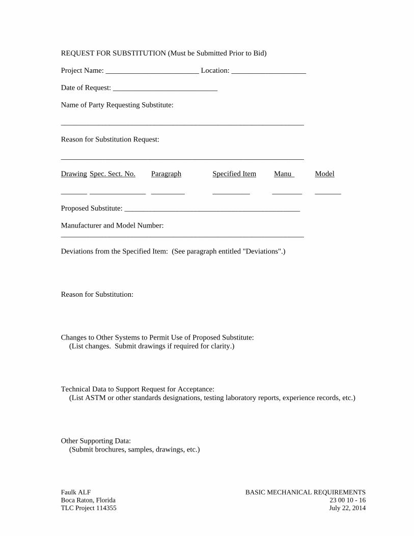
REQUEST FOR SUBSTITUTION (Must be Submitted Prior to Bid) Project Name: _________________________ Location: ____________________ Date of Request: ____________________________ Name of Party Requesting Substitute: _________________________________________________________________ Reason for Substitution Request: _________________________________________________________________ Drawing Spec. Sect. No. Paragraph Specified Item Manu Model _______ _______________ _________ __________ ________ _______ Proposed Substitute: _______________________________________________ Manufacturer and Model Number: _________________________________________________________________ Deviations from the Specified Item: (See paragraph entitled "Deviations".) Reason for Substitution: Changes to Other Systems to Permit Use of Proposed Substitute:
(List changes. Submit drawings if required for clarity.) Technical Data to Support Request for Acceptance:
(List ASTM or other standards designations, testing laboratory reports, experience records, etc.) Other Supporting Data:
(Submit brochures, samples, drawings, etc.)
Faulk ALF BASIC MECHANICAL REQUIREMENTS Boca Raton, Florida 23 00 10 - 16 TLC Project 114355 July 22, 2014
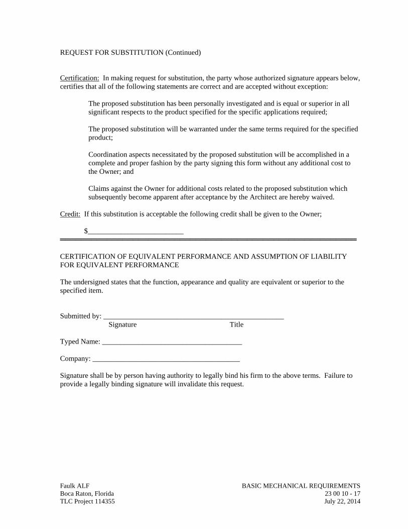
Faulk ALF BASIC MECHANICAL REQUIREMENTS Boca Raton, Florida 23 00 10 - 17 TLC Project 114355 July 22, 2014
REQUEST FOR SUBSTITUTION (Continued) Certification: In making request for substitution, the party whose authorized signature appears below, certifies that all of the following statements are correct and are accepted without exception:
The proposed substitution has been personally investigated and is equal or superior in all significant respects to the product specified for the specific applications required;
The proposed substitution will be warranted under the same terms required for the specified product;
Coordination aspects necessitated by the proposed substitution will be accomplished in a complete and proper fashion by the party signing this form without any additional cost to the Owner; and
Claims against the Owner for additional costs related to the proposed substitution which subsequently become apparent after acceptance by the Architect are hereby waived.
Credit: If this substitution is acceptable the following credit shall be given to the Owner; $__________________________ ═════════════════════════════════════════════════════════ CERTIFICATION OF EQUIVALENT PERFORMANCE AND ASSUMPTION OF LIABILITY FOR EQUIVALENT PERFORMANCE The undersigned states that the function, appearance and quality are equivalent or superior to the specified item. Submitted by: _________________________________________________ Signature Title Typed Name: ______________________________________ Company: ________________________________________ Signature shall be by person having authority to legally bind his firm to the above terms. Failure to provide a legally binding signature will invalidate this request.
SECTION 23 05 00 COMMON WORK RESULTS FOR HVAC
Faulk ALF COMMON WORK RESULTS FOR HVAC Boca Raton, Florida 23 05 00 - 1 TLC Project 114355 July 22, 2014
PART 1 - GENERAL
1.01 RELATED DOCUMENTS
A. Drawings and general provisions of the Contract, including General and Supplementary Conditions and Division 01 Specification Sections, apply to this Section.
1.02 SUMMARY
A. This Section includes the following:
1. Piping materials and installation instructions common to most piping systems. 2. Dielectric fittings. 3. Mechanical sleeve seals. 4. Sleeves. 5. Equipment installation requirements common to equipment sections. 6. Concrete bases. 7. Supports and anchorages.
1.03 DEFINITIONS
A. Finished Spaces: Spaces other than mechanical and electrical equipment rooms, furred spaces, pipe and duct chases, unheated spaces immediately below roof, spaces above ceilings, unexcavated spaces, crawlspaces, and tunnels.
B. Exposed, Interior Installations: Exposed to view indoors. Examples include finished occupied spaces and mechanical equipment rooms.
C. Exposed, Exterior Installations: Exposed to view outdoors or subject to outdoor ambient temperatures and weather conditions. Examples include rooftop locations.
D. Concealed, Interior Installations: Concealed from view and protected from physical contact by building occupants. Examples include above ceilings and chases.
E. Concealed, Exterior Installations: Concealed from view and protected from weather conditions and physical contact by building occupants but subject to outdoor ambient temperatures. Examples include installations within unheated shelters.
F. The following are industry abbreviations for plastic materials:
1. CPVC: Chlorinated polyvinyl chloride plastic. 2. PVC: Polyvinyl chloride plastic.
G. The following are industry abbreviations for rubber materials:
1. EPDM: Ethylene-propylene-diene terpolymer rubber. 2. NBR: Acrylonitrile-butadiene rubber.
1.04 SUBMITTALS
A. Product Data: For the following:
1. Dielectric fittings. 2. Mechanical sleeve seals. 3. Escutcheons.
B. Welding certificates.
1.05 QUALITY ASSURANCE
A. Steel Support Welding: Qualify processes and operators according to AWS D1.1, "Structural Welding Code--Steel."
B. Steel Pipe Welding: Qualify processes and operators according to ASME Boiler and Pressure Vessel Code: Section IX, "Welding and Brazing Qualifications."
1. Comply with provisions in ASME B31 Series, "Code for Pressure Piping."
2. Certify that each welder has passed AWS qualification tests for welding processes involved and that certification is current.
C. Electrical Characteristics for HVAC Equipment: Equipment of higher electrical characteristics may be furnished provided such proposed equipment is approved in writing and connecting electrical services, circuit breakers, and conduit sizes are appropriately modified. If minimum energy ratings or efficiencies are specified, equipment shall comply with requirements.
1.06 DELIVERY, STORAGE, AND HANDLING
A. Deliver pipes and tubes with factory-applied end caps. Maintain end caps through shipping, storage, and handling to prevent pipe end damage and to prevent entrance of dirt, debris, and moisture.
B. Store plastic pipes protected from direct sunlight. Support to prevent sagging and bending.
1.07 COORDINATION
A. Arrange for pipe spaces, chases, slots, and openings in building structure during progress of construction, to allow for HVAC installations.
B. Coordinate installation of required supporting devices and set sleeves in poured-in-place concrete and other structural components as they are constructed.
C. Coordinate requirements for access panels and doors for HVAC items requiring access that are concealed behind finished surfaces. Access panels and doors are specified in Division 08 Section "Access Doors and Frames".
Faulk ALF COMMON WORK RESULTS FOR HVAC Boca Raton, Florida 23 05 00 - 2 TLC Project 114355 July 22, 2014
PART 2 - PRODUCTS
2.01 MANUFACTURERS
A. In other Part 2 articles where subparagraph titles below introduce lists, the following requirements apply for product selection:
1. Manufacturers: Subject to compliance with requirements, manufacturers offering products that may be incorporated into the Work include, but are not limited to, the manufacturers specified.
2.02 PIPE, TUBE, AND FITTINGS
A. Refer to individual Division 23 piping Sections for pipe, tube, and fitting materials and joining methods.
B. Pipe Threads: ASME B1.20.1 for factory-threaded pipe and pipe fittings.
2.03 JOINING MATERIALS
A. Refer to individual Division 23 piping Sections for special joining materials not listed below.
B. Pipe-Flange Gasket Materials: Suitable for chemical and thermal conditions of piping system contents.
1. ASME B16.21, nonmetallic, flat, asbestos-free, 1/8-inch maximum thickness unless thickness or specific material is indicated.
a. Full-Face Type: For flat-face, Class 125, cast-iron and cast-bronze flanges. b. Narrow-Face Type: For raised-face, Class 250, cast-iron and steel flanges.
2. AWWA C110, rubber, flat face, 1/8 inch thick, unless otherwise indicated; and full-face or ring type, unless otherwise indicated.
C. Flange Bolts and Nuts: ASME B18.2.1, carbon steel, unless otherwise indicated.
D. Plastic, Pipe-Flange Gasket, Bolts, and Nuts: Type and material recommended by piping system manufacturer, unless otherwise indicated.
E. Solder Filler Metals: ASTM B 32, lead-free alloys. Include water-flushable flux according to ASTM B 813.
F. Brazing Filler Metals: AWS A5.8, BCuP Series, copper-phosphorus alloys for general-duty brazing, unless otherwise indicated; and AWS A5.8, BAg1, silver alloy for refrigerant piping, unless otherwise indicated.
G. Welding Filler Metals: Comply with AWS D10.12 for welding materials appropriate for wall thickness and chemical analysis of steel pipe being welded.
Faulk ALF COMMON WORK RESULTS FOR HVAC Boca Raton, Florida 23 05 00 - 3 TLC Project 114355 July 22, 2014
H. Solvent Cements for Joining Plastic Piping:
1. CPVC Piping: ASTM F 493. 2. PVC Piping: ASTM D 2564. Include primer according to ASTM F 656.
2.04 DIELECTRIC FITTINGS
A. Description: Combination fitting of copper alloy and ferrous materials with threaded, solder-joint, plain, or weld-neck end connections that match piping system materials.
B. Insulating Material: Suitable for system fluid, pressure, and temperature.
C. Dielectric Unions: Factory-fabricated, union assembly, for 250-psig minimum working pressure at 180 deg F.
1. Manufacturers:
a. Epco Sales, Inc. b. Watts Industries, Inc.; Water Products Div. c. Zurn Industries, Inc.; Wilkins Div.
D. Dielectric Flanges: Factory-fabricated, companion-flange assembly, for 150- or 300-psig minimum working pressure as required to suit system pressures.
1. Manufacturers:
a. Capitol Manufacturing Co. b. Epco Sales, Inc. c. Watts Industries, Inc.; Water Products Div.
E. Dielectric-Flange Kits: Companion-flange assembly for field assembly. Include flanges, full-face- or ring-type neoprene or phenolic gasket, phenolic or polyethylene bolt sleeves, phenolic washers, and steel backing washers.
1. Manufacturers:
a. Advance Products & Systems, Inc. b. Calpico, Inc. c. Central Plastics Company. d. Pipeline Seal and Insulator, Inc.
2. Separate companion flanges and steel bolts and nuts shall have 150- or 300-psig minimum working pressure where required to suit system pressures.
F. Dielectric Couplings: Galvanized-steel coupling with inert and noncorrosive, thermoplastic lining; threaded ends; and 300-psig minimum working pressure at 225 deg F.
1. Manufacturers:
a. Calpico, Inc. b. Lochinvar Corp.
Faulk ALF COMMON WORK RESULTS FOR HVAC Boca Raton, Florida 23 05 00 - 4 TLC Project 114355 July 22, 2014
G. Dielectric Nipples: Electroplated steel nipple with inert and noncorrosive, thermoplastic lining; plain, threaded, or grooved ends; and 300-psig minimum working pressure at 225 deg F.
1. Manufacturers:
a. Perfection Corp. b. Precision Plumbing Products, Inc. c. Sioux Chief Manufacturing Co., Inc. d. Victaulic Co. of America.
2.05 MECHANICAL SLEEVE SEALS
A. Description: Modular sealing element unit, designed for field assembly, to fill annular space between pipe and sleeve.
1. Manufacturers:
a. Advance Products & Systems, Inc. b. Calpico, Inc. c. Metraflex Co. d. Pipeline Seal and Insulator, Inc.
2. Sealing Elements: EPDM interlocking links shaped to fit surface of pipe. Include type and number required for pipe material and size of pipe.
3. Pressure Plates: Carbon steel. Include two for each sealing element.
4. Connecting Bolts and Nuts: Carbon steel with corrosion-resistant coating of length required to secure pressure plates to sealing elements. Include one for each sealing element.
2.06 SLEEVES
A. Galvanized-Steel Sheet: 0.0239-inch minimum thickness; round tube closed with welded longitudinal joint.
B. Steel Pipe: ASTM A 53, Type E, Grade B, Schedule 40, galvanized, plain ends.
C. Cast Iron: Cast or fabricated "wall pipe" equivalent to ductile-iron pressure pipe, with plain ends and integral waterstop, unless otherwise indicated.
D. Stack Sleeve Fittings: Manufactured, cast-iron sleeve with integral clamping flange. Include clamping ring and bolts and nuts for membrane flashing.
1. Underdeck Clamp: Clamping ring with set screws.
Faulk ALF COMMON WORK RESULTS FOR HVAC Boca Raton, Florida 23 05 00 - 5 TLC Project 114355 July 22, 2014
PART 3 - EXECUTION
3.01 PIPING SYSTEMS - COMMON REQUIREMENTS
A. Install piping according to the following requirements and Division 23 Sections specifying piping systems.
B. Drawing plans, schematics, and diagrams indicate general location and arrangement of piping systems. Indicated locations and arrangements were used to size pipe and calculate friction loss, expansion, pump sizing, and other design considerations. Install piping as indicated unless deviations to layout are approved on Coordination Drawings.
C. Install piping in concealed locations, unless otherwise indicated and except in equipment rooms and service areas.
D. Install piping indicated to be exposed and piping in equipment rooms and service areas at right angles or parallel to building walls. Diagonal runs are prohibited unless specifically indicated otherwise.
E. Install piping above accessible ceilings to allow sufficient space for ceiling panel removal.
F. Install piping to permit valve servicing.
G. Install piping at indicated slopes.
H. Install piping free of sags and bends.
I. Install fittings for changes in direction and branch connections.
J. Install piping to allow application of insulation.
K. Select system components with pressure rating equal to or greater than system operating pressure.
L. Install escutcheons for penetrations of walls, ceilings, and floors according to the following:
1. New Piping:
a. Piping with Fitting or Sleeve Protruding from Wall: One-piece, deep-pattern type.
b. Insulated Piping: One-piece, stamped-steel type with spring clips. c. Bare Piping at Wall and Floor Penetrations in Finished Spaces: One-piece,
cast-brass type with polished chrome-plated finish. d. Bare Piping at Ceiling Penetrations in Finished Spaces: One-piece or split-
casting, cast-brass type with polished chrome-plated finish.
M. Sleeves are not required for core-drilled holes.
N. Install sleeves for pipes passing through concrete and masonry walls, gypsum-board partitions, and concrete floor and roof slabs.
Faulk ALF COMMON WORK RESULTS FOR HVAC Boca Raton, Florida 23 05 00 - 6 TLC Project 114355 July 22, 2014
1. Cut sleeves to length for mounting flush with both surfaces.
a. Exception: Extend sleeves installed in floors of mechanical equipment areas or other wet areas 2 inches above finished floor level. Extend cast-iron sleeve fittings below floor slab as required to secure clamping ring if ring is specified.
2. Install sleeves in new walls and slabs as new walls and slabs are constructed.
3. Install sleeves that are large enough to provide 1/4-inch annular clear space between sleeve and pipe or pipe insulation. Use the following sleeve materials:
a. Steel Pipe Sleeves: For pipes smaller than NPS 6.
b. Steel Sheet Sleeves: For pipes NPS 6 and larger, penetrating gypsum-board partitions.
c. Stack Sleeve Fittings: For pipes penetrating floors with membrane waterproofing. Secure flashing between clamping flanges. Install section of cast-iron soil pipe to extend sleeve to 2 inches above finished floor level. Refer to Division 07 Section "Sheet Metal Flashing and Trim" for flashing.
1) Seal space outside of sleeve fittings with grout.
4. Except for underground wall penetrations, seal annular space between sleeve and pipe or pipe insulation, using joint sealants appropriate for size, depth, and location of joint. Refer to Division 07 Section "Joint Sealants" for materials and installation.
O. Aboveground, Exterior-Wall Pipe Penetrations: Seal penetrations using sleeves and mechanical sleeve seals. Select sleeve size to allow for 1-inch annular clear space between pipe and sleeve for installing mechanical sleeve seals.
1. Install steel pipe for sleeves smaller than 6 inches in diameter.
2. Install cast-iron "wall pipes" for sleeves 6 inches and larger in diameter.
3. Mechanical Sleeve Seal Installation: Select type and number of sealing elements required for pipe material and size. Position pipe in center of sleeve. Assemble mechanical sleeve seals and install in annular space between pipe and sleeve. Tighten bolts against pressure plates that cause sealing elements to expand and make watertight seal.
P. Underground, Exterior-Wall Pipe Penetrations: Install cast-iron "wall pipes" for sleeves. Seal pipe penetrations using mechanical sleeve seals. Select sleeve size to allow for 1-inch annular clear space between pipe and sleeve for installing mechanical sleeve seals.
1. Mechanical Sleeve Seal Installation: Select type and number of sealing elements required for pipe material and size. Position pipe in center of sleeve. Assemble mechanical sleeve seals and install in annular space between pipe and sleeve. Tighten bolts against pressure plates that cause sealing elements to expand and make watertight seal.
Faulk ALF COMMON WORK RESULTS FOR HVAC Boca Raton, Florida 23 05 00 - 7 TLC Project 114355 July 22, 2014
Q. Fire-Barrier Penetrations: Maintain indicated fire rating of walls, partitions, ceilings, and floors at pipe penetrations. Seal pipe penetrations with firestop materials. Refer to Division 07 Section "Penetration Firestopping" for materials.
R. Verify final equipment locations for roughing-in.
S. Refer to equipment specifications in other Sections of these Specifications for roughing-in requirements.
3.02 PIPING JOINT CONSTRUCTION
A. Join pipe and fittings according to the following requirements and Division 23 Sections specifying piping systems.
B. Ream ends of pipes and tubes and remove burrs. Bevel plain ends of steel pipe.
C. Remove scale, slag, dirt, and debris from inside and outside of pipe and fittings before assembly.
D. Soldered Joints: Apply ASTM B 813, water-flushable flux, unless otherwise indicated, to tube end. Construct joints according to ASTM B 828 or CDA's "Copper Tube Handbook," using lead-free solder alloy complying with ASTM B 32.
E. Brazed Joints: Construct joints according to AWS's "Brazing Handbook," "Pipe and Tube" Chapter, using copper-phosphorus brazing filler metal complying with AWS A5.8.
F. Threaded Joints: Thread pipe with tapered pipe threads according to ASME B1.20.1. Cut threads full and clean using sharp dies. Ream threaded pipe ends to remove burrs and restore full ID. Join pipe fittings and valves as follows:
1. Apply appropriate tape or thread compound to external pipe threads unless dry seal threading is specified.
2. Damaged Threads: Do not use pipe or pipe fittings with threads that are corroded or damaged. Do not use pipe sections that have cracked or open welds.
G. Welded Joints: Construct joints according to AWS D10.12, using qualified processes and welding operators according to Part 1 "Quality Assurance" Article.
H. Flanged Joints: Select appropriate gasket material, size, type, and thickness for service application. Install gasket concentrically positioned. Use suitable lubricants on bolt threads.
3.03 PIPING CONNECTIONS
A. Make connections according to the following, unless otherwise indicated:
1. Install unions, in piping NPS 2 and smaller, adjacent to each valve and at final connection to each piece of equipment.
2. Install flanges, in piping NPS 2-1/2 and larger, adjacent to flanged valves and at final connection to each piece of equipment.
Faulk ALF COMMON WORK RESULTS FOR HVAC Boca Raton, Florida 23 05 00 - 8 TLC Project 114355 July 22, 2014
Faulk ALF COMMON WORK RESULTS FOR HVAC Boca Raton, Florida 23 05 00 - 9 TLC Project 114355 July 22, 2014
3. Wet Piping Systems: Install dielectric coupling and nipple fittings to connect piping materials of dissimilar metals.
3.04 EQUIPMENT INSTALLATION - COMMON REQUIREMENTS
A. Install equipment to allow maximum possible headroom unless specific mounting heights are not indicated.
B. Install equipment level and plumb, parallel and perpendicular to other building systems and components in exposed interior spaces, unless otherwise indicated.
C. Install HVAC equipment to facilitate service, maintenance, and repair or replacement of components. Connect equipment for ease of disconnecting, with minimum interference to other installations. Extend grease fittings to accessible locations.
D. Install equipment to allow right of way for piping installed at required slope.
3.05 CONCRETE BASES
A. Concrete Bases: Anchor equipment to concrete base according to equipment manufacturer's written instructions and according to seismic codes at Project.
1. Construct concrete bases of dimensions indicated, but not less than 4 inches larger in both directions than supported unit.
2. Install dowel rods to connect concrete base to concrete floor. Unless otherwise indicated, install dowel rods on 18-inch centers around the full perimeter of the base.
3. Install epoxy-coated anchor bolts for supported equipment that extend through concrete base, and anchor into structural concrete floor.
4. Place and secure anchorage devices. Use supported equipment manufacturer's setting drawings, templates, diagrams, instructions, and directions furnished with items to be embedded.
5. Install anchor bolts to elevations required for proper attachment to supported equipment.
6. Install anchor bolts according to anchor-bolt manufacturer's written instructions. 7. Use 3000-psi , 28-day compressive-strength concrete and reinforcement as specified
in Division 03 Section "Cast-in-Place Concrete".
3.06 ERECTION OF METAL SUPPORTS AND ANCHORAGES
A. Refer to Division 5 Section "Metal Fabrications" for structural steel.
B. Cut, fit, and place miscellaneous metal supports accurately in location, alignment, and elevation to support and anchor HVAC materials and equipment.
C. Field Welding: Comply with AWS D1.1.
END OF SECTION 23 05 00
SECTION 23 05 13
COMMON MOTOR REQUIREMENTS FOR HVAC EQUIPMENT
Faulk ALF COMMON WORK RESULTS FOR HVAC Boca Raton, Florida 23 05 13 - 1 TLC Project 114355 July 22, 2014
PART 1 - GENERAL
1.01 RELATED DOCUMENTS
A. Drawings and general provisions of the Contract, including General and Supplementary Conditions and Division 01 Specification Sections, apply to this Section.
1.02 SUMMARY
A. Section includes general requirements for single-phase and poly-phase, general-purpose, horizontal, small and medium, squirrel-cage induction motors for use on ac power systems up to 600 V and installed at equipment manufacturer's factory or shipped separately by equipment manufacturer for field installation.
1.03 COORDINATION
A. Coordinate features of motors, installed units, and accessory devices to be compatible with the following:
1. Motor controllers. 2. Torque, speed, and horsepower requirements of the load. 3. Ratings and characteristics of supply circuit and required control sequence. 4. Ambient and environmental conditions of installation location.
PART 2 - PRODUCTS
2.01 GENERAL MOTOR REQUIREMENTS
A. Comply with requirements in this Section except when stricter requirements are specified in HVAC equipment schedules or Sections.
B. Comply with NEMA MG 1 unless otherwise indicated.
C. Comply with IEEE 841 for severe-duty motors.
2.02 MOTOR CHARACTERISTICS
A. Duty: Continuous duty at ambient temperature of 40 deg C and at altitude of 3300 feet above sea level.
B. Capacity and Torque Characteristics: Sufficient to start, accelerate, and operate connected loads at designated speeds, at installed altitude and environment, with indicated operating sequence, and without exceeding nameplate ratings or considering service factor.
2.03 POLYPHASE MOTORS
A. Description: NEMA MG 1, Design B, medium induction motor.
B. Efficiency: Energy efficient, as defined in NEMA MG 1.
C. Service Factor: 1.15.
D. Multispeed Motors: Variable torque.
1. For motors with 2:1 speed ratio, consequent pole, single winding. 2. For motors with other than 2:1 speed ratio, separate winding for each speed.
E. Rotor: Random-wound, squirrel cage.
F. Bearings: Regreasable, shielded, antifriction ball bearings suitable for radial and thrust loading.
G. Temperature Rise: Match insulation rating.
H. Insulation: Class F.
I. Code Letter Designation:
1. Motors 15 HP and Larger: NEMA starting Code F or Code G. 2. Motors Smaller than 15 HP: Manufacturer's standard starting characteristic.
J. Enclosure Material: Cast iron for motor frame sizes 324T and larger; rolled steel for motor frame sizes smaller than 324T.
2.04 POLYPHASE MOTORS WITH ADDITIONAL REQUIREMENTS
A. Motors Used with Reduced-Voltage and Multispeed Controllers: Match wiring connection requirements for controller with required motor leads. Provide terminals in motor terminal box, suited to control method.
B. Motors Used with Variable Frequency Controllers: Ratings, characteristics, and features coordinated with and approved by controller manufacturer.
1. Windings: Copper magnet wire with moisture-resistant insulation varnish, designed and tested to resist transient spikes, high frequencies, and short time rise pulses produced by pulse-width modulated inverters.
2. Energy- and Premium-Efficient Motors: Class B temperature rise; Class F insulation.
3. Inverter-Duty Motors: Class F temperature rise; Class H insulation.
4. Thermal Protection: Comply with NEMA MG 1 requirements for thermally protected motors.
5. Shaft Grounding Rings:
a. All motors controlled by Variable Frequency Controllers shall be equipped with Shaft Grounding Ring kits. Kits shall be installed by motor or equipment manufacturer or installed in the field by contractor in accordance with NEMA MG-1 31.4.4.3. Shaft Grounding Ring kits shall be manufactured by AEGIS or approved equal.
Faulk ALF COMMON WORK RESULTS FOR HVAC Boca Raton, Florida 23 05 13 - 2 TLC Project 114355 July 22, 2014
Faulk ALF COMMON WORK RESULTS FOR HVAC Boca Raton, Florida 23 05 13 - 3 TLC Project 114355 July 22, 2014
b. Ensure Shaft Grounding Kit is installed on motors in accordance with the manufacturer’s recommendations.
c. Motors shall be NEMA Premium® and inverter duty and have class F, G or H insulation and have the capability to install Shaft Grounding Ring. Motors shall be Marathon (Mod Central), Baldor (Mod Express) or approved equal.
C. Severe-Duty Motors: Comply with IEEE 841, with 1.15 minimum service factor.
2.05 SINGLE-PHASE MOTORS
A. Motors larger than 1/20 hp shall be one of the following, to suit starting torque and requirements of specific motor application:
1. Permanent-split capacitor. 2. Split phase. 3. Capacitor start, inductor run. 4. Capacitor start, capacitor run.
B. Multispeed Motors: Variable-torque, permanent-split-capacitor type.
C. Bearings: Prelubricated, antifriction ball bearings or sleeve bearings suitable for radial and thrust loading.
D. Motors 1/20 HP and Smaller: Shaded-pole type.
E. Thermal Protection: Internal protection to automatically open power supply circuit to motor when winding temperature exceeds a safe value calibrated to temperature rating of motor insulation. Thermal-protection device shall automatically reset when motor temperature returns to normal range.
PART 3 - EXECUTION (Not Applicable)
END OF SECTION 23 05 13
SECTION 23 05 17
SLEEVES AND SLEEVE SEALS FOR HVAC PIPING
Faulk ALF SLEEVES AND SLEEVE SEALS FOR HVAC PIPING Boca Raton, Florida 23 05 17 - 1 TLC Project 114355 July 22, 2014
PART 1 - GENERAL
1.01 RELATED DOCUMENTS
A. Drawings and general provisions of the Contract, including General and Supplementary Conditions and Division 01 Specification Sections, apply to this Section.
1.02 SUMMARY
A. Section Includes:
1. Sleeves. 2. Stack-sleeve fittings. 3. Sleeve-seal systems. 4. Sleeve-seal fittings. 5. Grout.
1.03 ACTION SUBMITTALS
A. Product Data: For each type of product indicated.
PART 2 - PRODUCTS
2.01 SLEEVES
A. Galvanized-Steel Wall Pipes: ASTM A 53/A 53M, Schedule 40, with plain ends and welded steel collar; zinc coated.
B. Galvanized-Steel-Pipe Sleeves: ASTM A 53/A 53M, Type E, Grade B, Schedule 40, zinc coated, with plain ends.
C. Galvanized-Steel-Sheet Sleeves: 0.0239-inch minimum thickness; round tube closed with welded longitudinal joint.
D. Molded-PE or -PP Sleeves: Removable, tapered-cup shaped, and smooth outer surface with nailing flange for attaching to wooden forms.
E. Molded-PVC Sleeves: With nailing flange for attaching to wooden forms.
2.02 STACK-SLEEVE FITTINGS
A. Manufacturers: Subject to compliance with requirements, available manufacturers offering products that may be incorporated into the Work include, but are not limited to, the following:
1. Smith, Jay R. Mfg. Co. 2. Zurn Specification Drainage Operation; Zurn Plumbing Products Group.
B. Description: Manufactured, cast-iron sleeve with integral clamping flange. Include clamping ring, bolts, and nuts for membrane flashing.
1. Underdeck Clamp: Clamping ring with setscrews.
2.03 SLEEVE-SEAL SYSTEMS
A. Manufacturers: Subject to compliance with requirements, provide products by one of the following:
1. Advance Products & Systems, Inc. 2. CALPICO, Inc. 3. Metraflex Company (The). 4. Pipeline Seal and Insulator, Inc. 5. Proco Products, Inc.
B. Description: Modular sealing-element unit, designed for field assembly, for filling annular space between piping and sleeve.
1. Sealing Elements: EPDM-rubber interlocking links shaped to fit surface of pipe. Include type and number required for pipe material and size of pipe.
2. Pressure Plates: Carbon steel. 3. Connecting Bolts and Nuts: Stainless steel of length required to secure pressure
plates to sealing elements.
2.04 SLEEVE-SEAL FITTINGS
A. Manufacturers: Subject to compliance with requirements, provide products by one of the following:
1. Presealed Systems.
B. Description: Manufactured plastic, sleeve-type, waterstop assembly made for imbedding in concrete slab or wall. Unit has plastic or rubber waterstop collar with center opening to match piping OD.
2.05 GROUT
A. Standard: ASTM C 1107/C 1107M, Grade B, post-hardening and volume-adjusting, dry, hydraulic-cement grout.
B. Characteristics: Nonshrink; recommended for interior and exterior applications.
C. Design Mix: 5000-psi, 28-day compressive strength.
D. Packaging: Premixed and factory packaged.
PART 3 - EXECUTION
3.01 SLEEVE INSTALLATION
A. Install sleeves for piping passing through penetrations in floors, partitions, roofs, and walls. Faulk ALF SLEEVES AND SLEEVE SEALS FOR HVAC PIPING Boca Raton, Florida 23 05 17 - 2 TLC Project 114355 July 22, 2014
B. For sleeves that will have sleeve-seal system installed, select sleeves of size large enough to provide 1-inch annular clear space between piping and concrete slabs and walls.
1. Sleeves are not required for core-drilled holes.
C. Install sleeves in concrete floors, concrete roof slabs, and concrete walls as new slabs and walls are constructed.
1. Permanent sleeves are not required for holes in slabs formed by molded-PE or -PP sleeves.
2. Cut sleeves to length for mounting flush with both surfaces.
a. Exception: Extend sleeves installed in floors of mechanical equipment areas or other wet areas 2 inches above finished floor level.
3. Using grout, seal the space outside of sleeves in slabs and walls without sleeve-seal system.
D. Install sleeves for pipes passing through interior partitions.
1. Cut sleeves to length for mounting flush with both surfaces.
2. Install sleeves that are large enough to provide 1/4-inch annular clear space between sleeve and pipe or pipe insulation.
3. Seal annular space between sleeve and piping or piping insulation; use joint sealants appropriate for size, depth, and location of joint. Comply with requirements for sealants specified in Section 079200 "Joint Sealants."
E. Fire-Barrier Penetrations: Maintain indicated fire rating of walls, partitions, ceilings, and floors at pipe penetrations. Seal pipe penetrations with firestop materials. Comply with requirements for firestopping specified in Section 078413 "Penetration Firestopping."
3.02 STACK-SLEEVE-FITTING INSTALLATION
A. Install stack-sleeve fittings in new slabs as slabs are constructed. 1. Install fittings that are large enough to provide 1/4-inch annular clear space between
sleeve and pipe or pipe insulation.
2. Secure flashing between clamping flanges for pipes penetrating floors with membrane waterproofing. Comply with requirements for flashing specified in Section 076200 "Sheet Metal Flashing and Trim."
3. Install section of cast-iron soil pipe to extend sleeve to 2 inches above finished floor level.
4. Extend cast-iron sleeve fittings below floor slab as required to secure clamping ring if ring is specified.
5. Using grout, seal the space around outside of stack-sleeve fittings.
Faulk ALF SLEEVES AND SLEEVE SEALS FOR HVAC PIPING Boca Raton, Florida 23 05 17 - 3 TLC Project 114355 July 22, 2014
B. Fire-Barrier Penetrations: Maintain indicated fire rating of floors at pipe penetrations. Seal pipe penetrations with firestop materials. Comply with requirements for firestopping specified in Section 078413 "Penetration Firestopping."
3.03 SLEEVE-SEAL-SYSTEM INSTALLATION
A. Install sleeve-seal systems in sleeves in exterior concrete walls and slabs-on-grade at service piping entries into building.
B. Select type, size, and number of sealing elements required for piping material and size and for sleeve ID or hole size. Position piping in center of sleeve. Center piping in penetration, assemble sleeve-seal system components, and install in annular space between piping and sleeve. Tighten bolts against pressure plates that cause sealing elements to expand and make a watertight seal.
3.04 SLEEVE-SEAL-FITTING INSTALLATION
A. Install sleeve-seal fittings in new walls and slabs as they are constructed.
B. Assemble fitting components of length to be flush with both surfaces of concrete slabs and walls. Position waterstop flange to be centered in concrete slab or wall.
C. Secure nailing flanges to concrete forms.
D. Using grout, seal the space around outside of sleeve-seal fittings.
3.05 SLEEVE AND SLEEVE-SEAL SCHEDULE
A. Use sleeves and sleeve seals for the following piping-penetration applications:
1. Exterior Concrete Walls above Grade: a. Piping Smaller Than NPS 6. Galvanized-steel-pipe sleeves. b. Piping NPS 6 and Larger: Galvanized-steel-pipe sleeves.
2. Exterior Concrete Walls below Grade:
a. Piping Smaller Than NPS 6: Galvanized-steel-pipe sleeves with sleeve-seal system. 1) Select sleeve size to allow for 1-inch annular clear space between piping
and sleeve for installing sleeve-seal system.
b. Piping NPS 6 and Larger: Galvanized-steel-pipe sleeves with sleeve-seal system. 1) Select sleeve size to allow for 1-inch annular clear space between piping
and sleeve for installing sleeve-seal system.
3. Concrete Slabs-on-Grade: a. Piping Smaller Than NPS 6: Galvanized-steel-pipe sleeves with sleeve-seal
system.
1) Select sleeve size to allow for 1-inch annular clear space between piping and sleeve for installing sleeve-seal system.
Faulk ALF SLEEVES AND SLEEVE SEALS FOR HVAC PIPING Boca Raton, Florida 23 05 17 - 4 TLC Project 114355 July 22, 2014
Faulk ALF SLEEVES AND SLEEVE SEALS FOR HVAC PIPING Boca Raton, Florida 23 05 17 - 5 TLC Project 114355 July 22, 2014
b. Piping NPS 6 and Larger: Galvanized-steel-pipe sleeves with sleeve-seal system.
1) Select sleeve size to allow for 1-inch annular clear space between piping and sleeve for installing sleeve-seal system.
4. Concrete Slabs above Grade:
a. Piping Smaller Than NPS 6: PVC-pipe sleeves. b. Piping NPS 6 and Larger: PVC-pipe sleeves.
5. Interior Partitions:
a. Piping Smaller Than NPS 6: Galvanized-steel-pipe sleeves. b. Piping NPS 6 and Larger: Galvanized-steel-sheet sleeves.
END OF SECTION 23 05 17
SECTION 23 05 18
SLEEVES AND SLEEVE SEALS FOR HVAC PIPING
Faulk ALF ESCUTCHEONS FOR HVAC PIPING Boca Raton, Florida 23 05 18 - 1 TLC Project 114355 July 22, 2014
PART 1 - GENERAL
1.01 RELATED DOCUMENTS
A. Drawings and general provisions of the Contract, including General and Supplementary Conditions and Division 01 Specification Sections, apply to this Section.
1.02 SUMMARY
A. Section Includes:
1. Escutcheons. 2. Floor plates.
1.03 ACTION SUBMITTALS
A. Product Data: For each type of product indicated.
PART 2 - PRODUCTS
2.01 ESCUTCHEONS
A. One-Piece, Cast-Brass Type: With polished, chrome-plated and rough-brass finish and setscrew fastener.
B. One-Piece, Deep-Pattern Type: Deep-drawn, box-shaped brass with chrome-plated finish and spring-clip fasteners.
C. One-Piece, Stamped-Steel Type: With chrome-plated finish and spring-clip fasteners.
D. Split-Casting Brass Type: With polished, chrome-plated and rough-brass finish and with concealed hinge and setscrew.
E. Split-Plate, Stamped-Steel Type: With chrome-plated finish, concealed and exposed-rivet hinge, and spring-clip fasteners.
2.02 FLOOR PLATES
A. One-Piece Floor Plates: Cast-iron flange with holes for fasteners.
B. Split-Casting Floor Plates: Cast brass with concealed hinge.
PART 3 - EXECUTION
3.01 INSTALLATION
A. Install escutcheons for piping penetrations of walls, ceilings, and finished floors.
Faulk ALF ESCUTCHEONS FOR HVAC PIPING Boca Raton, Florida 23 05 18 - 2 TLC Project 114355 July 22, 2014
B. Install escutcheons with ID to closely fit around pipe, tube, and insulation of piping and with OD that completely covers opening.
1. Escutcheons for New Piping:
a. Piping with Fitting or Sleeve Protruding from Wall: One-piece, deep-pattern type.
b. Chrome-Plated Piping: One-piece, cast-brass or split-casting brass type with polished, chrome-plated finish.
c. Insulated Piping: One-piece, stamped-steel type or split-plate, stamped-steel type with concealed hinge.
d. Bare Piping at Wall and Floor Penetrations in Finished Spaces: One-piece, cast-brass or split-casting brass type with polished, chrome-plated finish.
e. Bare Piping at Wall and Floor Penetrations in Finished Spaces: One-piece, stamped-steel type or split-plate, stamped-steel type with concealed hinge.
f. Bare Piping at Ceiling Penetrations in Finished Spaces: One-piece, cast-brass or split-casting brass type with polished, chrome-plated finish.
g. Bare Piping at Ceiling Penetrations in Finished Spaces: One-piece, stamped-steel type or split-plate, stamped-steel type with concealed hinge.
h. Bare Piping in Unfinished Service Spaces: One-piece, cast-brass or split-casting brass type with polished, chrome-plated finish.
i. Bare Piping in Unfinished Service Spaces: One-piece, stamped-steel type.
j. Bare Piping in Equipment Rooms: One-piece, cast-brass or split-casting brass type with polished, chrome-plated finish.
k. Bare Piping in Equipment Rooms: One-piece, stamped-steel type or split-plate, stamped-steel type with concealed hinge.
C. Install floor plates for piping penetrations of equipment-room floors.
D. Install floor plates with ID to closely fit around pipe, tube, and insulation of piping and with OD that completely covers opening.
1. New Piping: One-piece, floor-plate type.
3.02 FIELD QUALITY CONTROL
A. Replace broken and damaged escutcheons and floor plates using new materials.
END OF SECTION 23 05 18
SECTION 23 05 19 METERS AND GAGES FOR HVAC PIPING
Faulk ALF METERS AND GAGES FOR HVAC PIPING Boca Raton, Florida 23 05 19 - 1 TLC Project 114355 July 22, 2014
PART 1 - GENERAL
1.01 RELATED DOCUMENTS
A. Drawings and general provisions of the Contract, including General and Supplementary Conditions and Division 01 Specification Sections, apply to this Section.
1.02 SUMMARY
A. Section Includes:
1. Light-activated thermometers. 2. Thermowells. 3. Dial-type pressure gages. 4. Gage attachments. 5. Test plugs. 6. Test-plug kits. 7. Sight flow indicators. 8. Venturi flowmeters.
1.03 ACTION SUBMITTALS
A. Product Data: For each type of product indicated.
B. Wiring Diagrams: For power, signal, and control wiring.
1.04 INFORMATIONAL SUBMITTALS
A. Product Certificates: For each type of meter and gage, from manufacturer.
1.05 CLOSEOUT SUBMITTALS
A. Operation and Maintenance Data: For meters and gages to include in operation and maintenance manuals.
PART 2 - PRODUCTS
2.01 LIGHT-ACTIVATED THERMOMETERS
A. Direct-Mounted, Light-Activated Thermometers:
1. Manufacturers: Subject to compliance with requirements, available manufacturers offering products that may be incorporated into the Work include, but are not limited to, the following:
a. Flo Fab Inc. b. REOTEMP Instrument Corporation. c. Trerice, H. O. Co. d. Weiss Instruments, Inc. e. WIKA Instrument Corporation - USA. f. Winters Instruments - U.S.
2. Case: Plastic; 7-inch nominal size unless otherwise indicated. 3. Scale(s): Deg F (Deg C). 4. Case Form: Adjustable angle. 5. Connector: 1-1/4 inches with ASME B1.1 screw threads.
6. Stem: Aluminum and of length to suit installation.
a. Design for Air-Duct Installation: With ventilated shroud. b. Design for Thermowell Installation: Bare stem.
7. Display: Digital. 8. Accuracy: Plus or minus 2 deg F.
B. Remote-Mounted, Light-Activated Thermometers:
1. Manufacturers: Subject to compliance with requirements, available manufacturers offering products that may be incorporated into the Work include, but are not limited to, the following:
a. Miljoco Corporation. b. Weiss Instruments, Inc. c. Winters Instruments - U.S.
2. Case: Plastic, for wall mounting. 3. Scale(s): Deg F (Deg C).
4. Sensor: Bulb and thermister wire:
a. Design for Air-Duct Installation: With ventilated shroud. b. Design for Thermowell Installation: Bare stem.
5. Display: Digital. 6. Accuracy: Plus or minus 2 deg F.
2.02 DUCT-THERMOMETER MOUNTING BRACKETS
A. Description: Flanged bracket with screw holes, for attachment to air duct and made to hold thermometer stem.
2.03 THERMOWELLS
A. Thermowells:
1. Standard: ASME B40.200. 2. Description: Pressure-tight, socket-type fitting made for insertion into piping tee
fitting. 3. Material for Use with Copper Tubing: CNR or CUNI. 4. Material for Use with Steel Piping: CRES. 5. Type: Stepped shank unless straight or tapered shank is indicated. 6. External Threads: NPS 1/2, NPS 3/4, or NPS 1, ASME B1.20.1 pipe threads. 7. Internal Threads: 1/2, 3/4, and 1 inch, with ASME B1.1 screw threads. 8. Bore: Diameter required to match thermometer bulb or stem. 9. Insertion Length: Length required to match thermometer bulb or stem. 10. Lagging Extension: Include on thermowells for insulated piping and tubing. 11. Bushings: For converting size of thermowell's internal screw thread to size of
thermometer connection. Faulk ALF METERS AND GAGES FOR HVAC PIPING Boca Raton, Florida 23 05 19 - 2 TLC Project 114355 July 22, 2014
B. Heat-Transfer Medium: Mixture of graphite and glycerin.
2.04 PRESSURE GAGES
A. Direct-Mounted, Metal-Case, Dial-Type Pressure Gages:
1. Manufacturers: Subject to compliance with requirements, provide products by one of the following:
a. AMETEK, Inc.; U.S. Gauge. b. Ashcroft Inc. c. Ernst Flow Industries. d. Flo Fab Inc. e. Marsh Bellofram. f. Miljoco Corporation. g. Noshok. h. Palmer Wahl Instrumentation Group. i. REOTEMP Instrument Corporation. j. Tel-Tru Manufacturing Company. k. Trerice, H. O. Co. l. Watts Regulator Co.; a div. of Watts Water Technologies, Inc. m. Weiss Instruments, Inc. n. WIKA Instrument Corporation - USA. o. Winters Instruments - U.S.
2. Standard: ASME B40.100. 3. Case: Liquid-filled type(s); cast aluminum or drawn steel; 4-1/2-inch nominal
diameter. 4. Pressure-Element Assembly: Bourdon tube unless otherwise indicated. 5. Pressure Connection: Brass, with NPS 1/4 or NPS 1/2, ASME B1.20.1 pipe
threads and bottom-outlet type unless back-outlet type is indicated. 6. Movement: Mechanical, with link to pressure element and connection to pointer. 7. Dial: Nonreflective aluminum with permanently etched scale markings
graduated in psi. 8. Pointer: Dark-colored metal. 9. Window: Glass. 10. Ring: Metal. 11. Accuracy: Grade A, plus or minus 1 percent of middle half of scale range.
2.05 GAGE ATTACHMENTS
A. Snubbers: ASME B40.100, brass; with NPS 1/4 or NPS 1/2, ASME B1.20.1 pipe threads and piston type surge-dampening device. Include extension for use on insulated piping.
B. Siphons: Loop-shaped section of brass pipe with NPS 1/4 or NPS 1/2 pipe threads.
C. Valves: Brass or stainless-steel needle, with NPS 1/4 or NPS 1/2, ASME B1.20.1 pipe threads.
2.06 TEST PLUGS
A. Manufacturers: Subject to compliance with requirements, provide products by one of the following:
1. Flow Design, Inc. Faulk ALF METERS AND GAGES FOR HVAC PIPING Boca Raton, Florida 23 05 19 - 3 TLC Project 114355 July 22, 2014
2. Miljoco Corporation. 3. National Meter, Inc. 4. Peterson Equipment Co., Inc. 5. Sisco Manufacturing Company, Inc. 6. Trerice, H. O. Co. 7. Watts Regulator Co.; a div. of Watts Water Technologies, Inc. 8. Weiss Instruments, Inc.
B. Description: Test-station fitting made for insertion into piping tee fitting.
C. Body: Brass or stainless steel with core inserts and gasketed and threaded cap. Include extended stem on units to be installed in insulated piping.
D. Thread Size: NPS 1/4, ASME B1.20.1 pipe thread.
E. Minimum Pressure and Temperature Rating: 500 psig at 200 deg F.
F. Core Inserts: Chlorosulfonated polyethylene synthetic and EPDM self-sealing rubber.
2.07 TEST-PLUG KITS
A. Manufacturers: Subject to compliance with requirements, provide products by one of the following:
1. Flow Design, Inc. 2. Miljoco Corporation. 3. National Meter, Inc. 4. Peterson Equipment Co., Inc. 5. Sisco Manufacturing Company, Inc. 6. Trerice, H. O. Co. 7. Watts Regulator Co.; a div. of Watts Water Technologies, Inc. 8. Weiss Instruments, Inc.
B. Furnish one test-plug kit(s) containing one thermometer(s), one pressure gage and adapter, and carrying case. Thermometer sensing elements, pressure gage, and adapter probes shall be of diameter to fit test plugs and of length to project into piping.
C. Low-Range Thermometer: Small, bimetallic insertion type with 1- to 2-inch diameter dial and tapered-end sensing element. Dial range shall be at least 25 to 125 deg F.
D. Pressure Gage: Small, Bourdon-tube insertion type with 2 to 3 inch diameter dial and probe. Dial range shall be at least 0 to 200 psig.
E. Carrying Case: Metal or plastic, with formed instrument padding.
2.08 SIGHT FLOW INDICATORS
A. Manufacturers: Subject to compliance with requirements, provide products by one of the following:
1. Archon Industries, Inc. 2. Dwyer Instruments, Inc. 3. Emerson Process Management; Brooks Instrument. 4. Ernst Co., John C., Inc. 5. Ernst Flow Industries. 6. KOBOLD Instruments, Inc. - USA; KOBOLD Messring GmbH.
Faulk ALF METERS AND GAGES FOR HVAC PIPING Boca Raton, Florida 23 05 19 - 4 TLC Project 114355 July 22, 2014
7. OPW Engineered Systems; a Dover company. 8. Penberthy; A Brand of Tyco Valves & Controls - Prophetstown.
B. Description: Piping inline-installation device for visual verification of flow.
C. Construction: Bronze or stainless-steel body, with sight glass and ball, flapper, or paddle wheel indicator, and threaded or flanged ends.
D. Minimum Pressure Rating: 125 psig.
E. Minimum Temperature Rating: 200 deg F.
F. End Connections for NPS 2 and Smaller: Threaded.
G. End Connections for NPS 2-1/2 and Larger: Flanged.
2.09 FLOWMETERS
A. Orifice Flowmeters:
1. Manufacturers: Subject to compliance with requirements, provide products by one of the following:
a. ABB; Instrumentation and Analytical. b. Bell & Gossett; ITT Industries. c. Meriam Process Technologies. d. Preso Meters; a division of Racine Federated Inc. e. S. A. Armstrong Limited; Armstrong Pumps Inc.
2. Description: Flowmeter with sensor, hoses or tubing, fittings, valves, indicator, and conversion chart.
3. Flow Range: Sensor and indicator shall cover operating range of equipment or system served.
4. Sensor: Wafer-orifice-type, calibrated, flow-measuring element; for installation between pipe flanges.
a. Design: Differential-pressure-type measurement for gas or water. b. Construction: Cast-iron body, brass valves with integral check valves and
caps, and calibrated nameplate. c. Minimum Pressure Rating: 300 psig. d. Minimum Temperature Rating: 250 deg F.
5. Permanent Indicators: Meter suitable for wall or bracket mounting, calibrated for connected sensor and having 6-inch- diameter, or equivalent, dial with fittings and copper tubing for connecting to sensor.
a. Scale: Gallons per minute. b. Accuracy: Plus or minus 1 percent between 20 and 80 percent of scale
range.
6. Portable Indicators: Hand-held, differential-pressure type, calibrated for connected sensor and having two 12-foot hoses, with carrying case.
a. Scale: Gallons per minute.
Faulk ALF METERS AND GAGES FOR HVAC PIPING Boca Raton, Florida 23 05 19 - 5 TLC Project 114355 July 22, 2014
b. Accuracy: Plus or minus 2 percent between 20 and 80 percent of scale range.
7. Display: Shows rate of flow, with register to indicate total volume in gallons.
8. Conversion Chart: Flow rate data compatible with sensor and indicator.
9. Operating Instructions: Include complete instructions with each flowmeter.
B. Venturi Flowmeters:
1. Manufacturers: Subject to compliance with requirements, provide products by one of the following:
a. ABB; Instrumentation and Analytical. b. Gerand Engineering Co. c. Hyspan Precision Products, Inc. d. Preso Meters; a division of Racine Federated Inc. e. S. A. Armstrong Limited; Armstrong Pumps Inc. f. Victaulic Company.
2. Description: Flowmeter with calibrated flow-measuring element, hoses or tubing, fittings, valves, indicator, and conversion chart.
3. Flow Range: Sensor and indicator shall cover operating range of equipment or system served.
4. Sensor: Venturi-type, calibrated, flow-measuring element; for installation in piping.
a. Design: Differential-pressure-type measurement for gas or water. b. Construction: Bronze, brass, or factory-primed steel, with brass fittings
and attached tag with flow conversion data. c. Minimum Pressure Rating: 250 psig. d. Minimum Temperature Rating: 250 deg F. e. End Connections for NPS 2 and Smaller: Threaded. f. End Connections for NPS 2-1/2 and Larger: Flanged or welded. g. Flow Range: Flow-measuring element and flowmeter shall cover
operating range of equipment or system served.
5. Permanent Indicators: Meter suitable for wall or bracket mounting, calibrated for connected flowmeter element, and having 6-inch- diameter, or equivalent, dial with fittings and copper tubing for connecting to flowmeter element.
a. Scale: Gallons per minute. b. Accuracy: Plus or minus 1 percent between 20 and 80 percent of scale
range.
6. Portable Indicators: Hand-held, differential-pressure type, calibrated for connected flowmeter element and having two 12-foot hoses, with carrying case.
a. Scale: Gallons per minute. b. Accuracy: Plus or minus 2 percent between 20 and 80 percent of scale
range.
Faulk ALF METERS AND GAGES FOR HVAC PIPING Boca Raton, Florida 23 05 19 - 6 TLC Project 114355 July 22, 2014
7. Display: Shows rate of flow, with register to indicate total volume in gallons. 8. Conversion Chart: Flow rate data compatible with sensor. 9. Operating Instructions: Include complete instructions with each flowmeter.
PART 3 - EXECUTION
3.01 INSTALLATION
A. Install thermowells with socket extending a minimum of 2 inches into fluid and in vertical position in piping tees.
B. Install thermowells of sizes required to match thermometer connectors. Include bushings if required to match sizes.
C. Install thermowells with extension on insulated piping.
D. Fill thermowells with heat-transfer medium.
E. Install direct-mounted thermometers in thermowells and adjust vertical and tilted positions.
F. Install remote-mounted thermometer bulbs in thermowells and install cases on panels; connect cases with tubing and support tubing to prevent kinks. Use minimum tubing length.
G. Install duct-thermometer mounting brackets in walls of ducts. Attach to duct with screws.
H. Install direct-mounted pressure gages in piping tees with pressure gage located on pipe at the most readable position.
I. Install remote-mounted pressure gages on panel.
J. Install valve and snubber in piping for each pressure gage for fluids (except steam).
K. Install valve and syphon fitting in piping for each pressure gage for steam.
L. Install test plugs in piping tees.
M. Install flow indicators in piping systems in accessible positions for easy viewing.
N. Assemble and install connections, tubing, and accessories between flow-measuring elements and flowmeters according to manufacturer's written instructions.
O. Install flowmeter elements in accessible positions in piping systems.
P. Install differential-pressure-type flowmeter elements, with at least minimum straight lengths of pipe, upstream and downstream from element according to manufacturer's written instructions.
Q. Install permanent indicators on walls or brackets in accessible and readable positions.
R. Install connection fittings in accessible locations for attachment to portable indicators.
Faulk ALF METERS AND GAGES FOR HVAC PIPING Boca Raton, Florida 23 05 19 - 7 TLC Project 114355 July 22, 2014
S. Install thermometers in the following locations:
1. Inlet and outlet of each hydronic zone. 2. Inlet and outlet of each hydronic boiler. 3. Two inlets and two outlets of each hydronic heat exchanger. 4. Outside-, return-, supply-, and mixed-air ducts.
T. Install pressure gages in the following locations:
1. Discharge of each pressure-reducing valve. 2. Inlet and outlet of each condenser water connection. 3. Suction and discharge of each pump.
3.02 CONNECTIONS
A. Install meters and gages adjacent to machines and equipment to allow service and maintenance of meters, gages, machines, and equipment.
B. Connect flowmeter-system elements to meters.
C. Connect flowmeter transmitters to meters.
D. Connect thermal-energy meter transmitters to meters.
3.03 ADJUSTING
A. After installation, calibrate meters according to manufacturer's written instructions.
B. Adjust faces of meters and gages to proper angle for best visibility.
3.04 THERMOMETER SCHEDULE
A. Thermometers at inlet and outlet of each hydronic zone shall be one of the following:
1. Liquid-filled, bimetallic-actuated type. 2. Direct mounted, metal case, vapor-actuated type. 3. Compact style, liquid-in-glass type. 4. Direct mounted, light-activated type. 5. Test plug with chlorosulfonated polyethylene synthetic or EPDM self-sealing
rubber inserts.
B. Thermometers at inlet and outlet of each hydronic boiler shall be one of the following:
1. Liquid-filled bimetallic-actuated type. 2. Direct mounted, metal case, vapor-actuated type. 3. Compact style, liquid-in-glass type. 4. Direct mounted, light-activated type. 5. Test plug with chlorosulfonated polyethylene synthetic or EPDM self-sealing
rubber inserts.
C. Thermometers at inlet and outlet of each hydronic coil in air-handling units and built-up central systems shall be one of the following:
1. Liquid-filled, bimetallic-actuated type. 2. Direct mounted, metal case, vapor-actuated type. 3. Compact style, liquid-in-glass type.
Faulk ALF METERS AND GAGES FOR HVAC PIPING Boca Raton, Florida 23 05 19 - 8 TLC Project 114355 July 22, 2014
4. Direct mounted, light-activated type. 5. Test plug with chlorosulfonated polyethylene synthetic or EPDM self-sealing
rubber inserts.
D. Thermometers at inlets and outlets of each hydronic heat exchanger shall be one of the following:
1. Liquid-filled, bimetallic-actuated type. 2. Direct mounted, metal case, vapor-actuated type. 3. Compact style, liquid-in-glass type. 4. Direct mounted, light-activated type. 5. Test plug with chlorosulfonated polyethylene synthetic or EPDM self-sealing
rubber inserts.
E. Thermometers at outside-, return-, supply-, and mixed-air ducts shall be one of the following:
1. Liquid-filled, bimetallic-actuated type. 2. Direct mounted, metal case, vapor-actuated type. 3. Compact style, liquid-in-glass type. 4. Direct mounted, light-activated type.
F. Thermometer stems shall be of length to match thermowell insertion length.
3.05 THERMOMETER SCALE RANGE SCHEDULE
A. Scale Range for Condenser-Water Piping: 0 to 250 deg F.
B. Scale Range for Air Ducts: 0 to 100 deg F.
3.06 PRESSURE-GAGE SCHEDULE
A. Pressure gages at discharge of each pressure-reducing valve shall be one of the following:
1. Liquid-filled, direct mounted, metal case. 2. Sealed, direct mounted, plastic case. 3. Test plug with chlorosulfonated polyethylene synthetic or EPDM self-sealing
rubber inserts.
B. Pressure gages at inlet and outlet of condenser-water connection shall be one of the following:
1. Liquid-filled, direct mounted, metal case. 2. Sealed, direct mounted, plastic case. 3. Test plug with chlorosulfonated polyethylene synthetic or EPDM self-sealing
rubber inserts.
C. Pressure gages at suction and discharge of each pump shall be one of the following:
1. Liquid-filled, direct mounted, metal case. 2. Sealed, direct mounted, plastic case. 3. Test plug with chlorosulfonated polyethylene synthetic or EPDM self-sealing
rubber inserts.
Faulk ALF METERS AND GAGES FOR HVAC PIPING Boca Raton, Florida 23 05 19 - 9 TLC Project 114355 July 22, 2014
Faulk ALF METERS AND GAGES FOR HVAC PIPING Boca Raton, Florida 23 05 19 - 10 TLC Project 114355 July 22, 2014
3.07 PRESSURE-GAGE SCALE-RANGE SCHEDULE
A. Scale Range for Condenser-Water Piping: 30 in. Hg to 15 psi.
B. Scale Range for Condenser-Water Piping: 0 to 100 psi.
3.08 FLOWMETER SCHEDULE
A. Flowmeters for Condenser-Water Piping: Venturi type.
END OF SECTION 23 05 19
SECTION 23 05 29
HANGERS & SUPPORTS FOR HVAC PIPING & EQUIPMENT
Faulk ALF HANGERS & SUPPORTS FOR HVAC PIPING & EQUIPMENT Boca Raton, Florida 23 05 29 - 1 TLC Project 114355 July 22, 2014
PART 1 - GENERAL
1.01 RELATED DOCUMENTS
A. Drawings and general provisions of the Contract, including General and Supplementary Conditions and Division 01 Specification Sections, apply to this Section.
1.02 SUMMARY
A. Section Includes:
1. Metal pipe hangers and supports. 2. Trapeze pipe hangers. 3. Fiberglass pipe hangers. 4. Metal framing systems. 5. Fiberglass strut systems. 6. Fastener systems. 7. Pipe stands. 8. Equipment supports.
1.03 DEFINITIONS
A. MSS: Manufacturers Standardization Society of The Valve and Fittings Industry Inc.
1.04 PERFORMANCE REQUIREMENTS
A. Delegated Design: Design trapeze pipe hangers and equipment supports, including comprehensive engineering analysis by a qualified professional engineer, using performance requirements and design criteria indicated.
B. Structural Performance: Hangers and supports for HVAC piping and equipment shall withstand the effects of gravity loads and stresses within limits and under conditions indicated according to ASCE/SEI 7.
1. Design supports for multiple pipes, including pipe stands, capable of supporting combined weight of supported systems, system contents, and test water.
2. Design equipment supports capable of supporting combined operating weight of supported equipment and connected systems and components.
1.05 ACTION SUBMITTALS
A. Product Data: For each type of product indicated.
B. Shop Drawings: Show fabrication and installation details and include calculations for the following; include Product Data for components:
1. Trapeze pipe hangers. 2. Metal framing systems.
3. Fiberglass strut systems. 4. Pipe stands. 5. Equipment supports.
C. Delegated-Design Submittal: For trapeze hangers indicated to comply with performance requirements and design criteria, including analysis data signed and sealed by the qualified professional engineer responsible for their preparation.
1. Detail fabrication and assembly of trapeze hangers. 2. Design Calculations: Calculate requirements for designing trapeze hangers.
1.06 INFORMATIONAL SUBMITTALS
A. Welding certificates.
1.07 QUALITY ASSURANCE
A. Structural Steel Welding Qualifications: Qualify procedures and personnel according to AWS D1.1/D1.1M, "Structural Welding Code - Steel."
B. Pipe Welding Qualifications: Qualify procedures and operators according to ASME Boiler and Pressure Vessel Code.
PART 2 - PRODUCTS
2.01 METAL PIPE HANGERS AND SUPPORTS
A. Carbon-Steel Pipe Hangers and Supports:
1. Description: MSS SP-58, Types 1 through 58, factory-fabricated components. 2. Galvanized Metallic Coatings: Pregalvanized or hot dipped. 3. Nonmetallic Coatings: Plastic coating, jacket, or liner. 4. Padded Hangers: Hanger with fiberglass or other pipe insulation pad or cushion to
support bearing surface of piping. 5. Hanger Rods: Continuous-thread rod, nuts, and washer made of carbon steel.
B. Stainless-Steel Pipe Hangers and Supports:
1. Description: MSS SP-58, Types 1 through 58, factory-fabricated components. 2. Padded Hangers: Hanger with fiberglass or other pipe insulation pad or cushion to
support bearing surface of piping. 3. Hanger Rods: Continuous-thread rod, nuts, and washer made of stainless steel.
C. Copper Pipe Hangers:
1. Description: MSS SP-58, Types 1 through 58, copper-coated-steel, factory-fabricated components.
2. Hanger Rods: Continuous-thread rod, nuts, and washer made of copper-coated steel or stainless steel.
Faulk ALF HANGERS & SUPPORTS FOR HVAC PIPING & EQUIPMENT Boca Raton, Florida 23 05 29 - 2 TLC Project 114355 July 22, 2014
2.02 TRAPEZE PIPE HANGERS
A. Description: MSS SP-69, Type 59, shop- or field-fabricated pipe-support assembly made from structural carbon-steel shapes with MSS SP-58 carbon-steel hanger rods, nuts, saddles, and U-bolts.
2.03 FIBERGLASS PIPE HANGERS
A. Clevis-Type, Fiberglass Pipe Hangers:
1. Description: Similar to MSS SP-58, Type 1, steel pipe hanger except hanger is made of fiberglass or fiberglass-reinforced resin.
2. Hanger Rods: Continuous-thread rod, washer, and nuts made of stainless steel.
B. Strap-Type, Fiberglass Pipe Hangers:
1. Description: Similar to MSS SP-58, Type 9 or Type 10, steel pipe hanger except hanger is made of fiberglass-reinforced resin.
2. Hanger Rod and Fittings: Continuous-thread rod, washer, and nuts made of stainless steel.
2.04 METAL FRAMING SYSTEMS
A. MFMA Manufacturer Metal Framing Systems:
1. Manufacturers: Subject to compliance with requirements, provide products by one of the following:
a. Allied Tube & Conduit. b. Cooper B-Line, Inc. c. Flex-Strut Inc. d. GS Metals Corp. e. Thomas & Betts Corporation. f. Unistrut Corporation; Tyco International, Ltd. g. Wesanco, Inc.
2. Description: Shop- or field-fabricated pipe-support assembly for supporting multiple parallel pipes.
3. Standard: MFMA-4. 4. Channels: Continuous slotted steel channel with inturned lips. 5. Channel Nuts: Formed or stamped steel nuts or other devices designed to fit into
channel slot and, when tightened, prevent slipping along channel. 6. Hanger Rods: Continuous-thread rod, nuts, and washer made of stainless steel. 7. Metallic Coating: Hot-dipped galvanized.
B. Non-MFMA Manufacturer Metal Framing Systems:
1. Manufacturers: Subject to compliance with requirements, provide products by one of the following:
a. Anvil International; a subsidiary of Mueller Water Products Inc.
Faulk ALF HANGERS & SUPPORTS FOR HVAC PIPING & EQUIPMENT Boca Raton, Florida 23 05 29 - 3 TLC Project 114355 July 22, 2014
b. Empire Industries, Inc. c. ERICO International Corporation. d. Haydon Corporation; H-Strut Division. e. NIBCO INC. f. PHD Manufacturing, Inc. g. PHS Industries, Inc.
2. Description: Shop- or field-fabricated pipe-support assembly made of steel channels, accessories, fittings, and other components for supporting multiple parallel pipes.
3. Standard: Comply with MFMA-4. 4. Channels: Continuous slotted steel channel with inturned lips. 5. Channel Nuts: Formed or stamped steel nuts or other devices designed to fit into
channel slot and, when tightened, prevent slipping along channel. 6. Hanger Rods: Continuous-thread rod, nuts, and washer made of stainless steel. 7. Coating: Zinc.
2.05 FIBERGLASS STRUT SYSTEMS
A. Manufacturers: Subject to compliance with requirements, provide products by one of the following:
1. Allied Tube & Conduit. 2. Champion Fiberglass, Inc. 3. Cooper B-Line, Inc. 4. SEASAFE, INC.; a Gibraltar Industries Company.
B. Description: Shop- or field-fabricated pipe-support assembly similar to MFMA-4 for supporting multiple parallel pipes.
1. Channels: Continuous slotted fiberglass or other plastic channel with inturned lips. 2. Channel Nuts: Fiberglass nuts or other devices designed to fit into channel slot and,
when tightened, prevent slipping along channel. 3. Hanger Rods: Continuous-thread rod, nuts, and washer made of stainless steel.
2.06 FASTENER SYSTEMS
A. Mechanical-Expansion Anchors: Insert-wedge-type, stainless steel anchors, for use in hardened portland cement concrete; with pull-out, tension, and shear capacities appropriate for supported loads and building materials where used.
2.07 PIPE STANDS
A. General Requirements for Pipe Stands: Shop- or field-fabricated assemblies made of manufactured corrosion-resistant components to support roof-mounted piping.
B. Compact Pipe Stand: One-piece plastic unit with integral-rod roller, pipe clamps, or V-shaped cradle to support pipe, for roof installation without membrane penetration.
C. Low-Type, Single-Pipe Stand: One-piece plastic base unit with plastic roller, for roof installation without membrane penetration.
Faulk ALF HANGERS & SUPPORTS FOR HVAC PIPING & EQUIPMENT Boca Raton, Florida 23 05 29 - 4 TLC Project 114355 July 22, 2014
D. High-Type, Single-Pipe Stand:
1. Description: Assembly of base, vertical and horizontal members, and pipe support, for roof installation without membrane penetration.
2. Base: Plastic. 3. Vertical Members: Two or more cadmium-plated-steel or stainless-steel, continuous-
thread rods. 4. Horizontal Member: Cadmium-plated-steel or stainless-steel rod with plastic or
stainless-steel, roller-type pipe support.
E. High-Type, Multiple-Pipe Stand:
1. Description: Assembly of bases, vertical and horizontal members, and pipe supports, for roof installation without membrane penetration.
2. Bases: One or more; plastic. 3. Vertical Members: Two or more protective-coated-steel channels. 4. Horizontal Member: Protective-coated-steel channel. 5. Pipe Supports: Galvanized-steel, clevis-type pipe hangers.
F. Curb-Mounted-Type Pipe Stands: Shop- or field-fabricated pipe supports made from structural-steel shapes, continuous-thread rods, and rollers, for mounting on permanent stationary roof curb.
2.08 EQUIPMENT SUPPORTS
A. Description: Welded, shop- or field-fabricated equipment support made from structural carbon-steel shapes.
2.09 MISCELLANEOUS MATERIALS
A. Structural Steel: ASTM A 36/A 36M, carbon-steel plates, shapes, and bars; black and galvanized.
B. Grout: ASTM C 1107, factory-mixed and -packaged, dry, hydraulic-cement, nonshrink and nonmetallic grout; suitable for interior and exterior applications.
1. Properties: Nonstaining, noncorrosive, and nongaseous. 2. Design Mix: 5000-psi, 28-day compressive strength.
PART 3 - EXECUTION
3.01 HANGER AND SUPPORT INSTALLATION A. Metal Pipe-Hanger Installation: Comply with MSS SP-69 and MSS SP-89. Install hangers,
supports, clamps, and attachments as required to properly support piping from the building structure.
B. Metal Trapeze Pipe-Hanger Installation: Comply with MSS SP-69 and MSS SP-89. Arrange for grouping of parallel runs of horizontal piping, and support together on field-fabricated trapeze pipe hangers.
Faulk ALF HANGERS & SUPPORTS FOR HVAC PIPING & EQUIPMENT Boca Raton, Florida 23 05 29 - 5 TLC Project 114355 July 22, 2014
1. Pipes of Various Sizes: Support together and space trapezes for smallest pipe size or install intermediate supports for smaller diameter pipes as specified for individual pipe hangers.
2. Field fabricate from ASTM A 36/A 36M, carbon-steel shapes selected for loads being supported. Weld steel according to AWS D1.1/D1.1M.
C. Fiberglass Pipe-Hanger Installation: Comply with applicable portions of MSS SP-69 and MSS SP-89. Install hangers and attachments as required to properly support piping from building structure.
D. Metal Framing System Installation: Arrange for grouping of parallel runs of piping, and support together on field-assembled metal framing systems.
E. Fiberglass Strut System Installation: Arrange for grouping of parallel runs of piping, and support together on field-assembled fiberglass struts.
F. Fastener System Installation:
1. Install mechanical-expansion anchors in concrete after concrete is placed and completely cured. Install fasteners according to manufacturer's written instructions.
G. Pipe Stand Installation:
1. Pipe Stand Types except Curb-Mounted Type: Assemble components and mount on smooth roof surface. Do not penetrate roof membrane.
2. Curb-Mounted-Type Pipe Stands: Assemble components or fabricate pipe stand and mount on permanent, stationary roof curb. See Section 077200 "Roof Accessories" for curbs.
H. Install hangers and supports complete with necessary attachments, inserts, bolts, rods, nuts, washers, and other accessories.
I. Equipment Support Installation: Fabricate from welded-structural-steel shapes.
J. Install hangers and supports to allow controlled thermal and seismic movement of piping systems, to permit freedom of movement between pipe anchors, and to facilitate action of expansion joints, expansion loops, expansion bends, and similar units.
K. Install lateral bracing with pipe hangers and supports to prevent swaying.
L. Install building attachments within concrete slabs or attach to structural steel. Install additional attachments at concentrated loads, including valves, flanges, and strainers, NPS 2-1/2 and larger and at changes in direction of piping. Install concrete inserts before concrete is placed; fasten inserts to forms and install reinforcing bars through openings at top of inserts.
M. Load Distribution: Install hangers and supports so that piping live and dead loads and stresses from movement will not be transmitted to connected equipment.
Faulk ALF HANGERS & SUPPORTS FOR HVAC PIPING & EQUIPMENT Boca Raton, Florida 23 05 29 - 6 TLC Project 114355 July 22, 2014
N. Pipe Slopes: Install hangers and supports to provide indicated pipe slopes and to not exceed maximum pipe deflections allowed by ASME B31.9 for building services piping.
3.02 EQUIPMENT SUPPORTS
A. Fabricate structural-steel stands to suspend equipment from structure overhead or to support equipment above floor.
B. Grouting: Place grout under supports for equipment and make bearing surface smooth.
C. Provide lateral bracing, to prevent swaying, for equipment supports.
3.03 METAL FABRICATIONS
A. Cut, drill, and fit miscellaneous metal fabrications for trapeze pipe hangers and equipment supports.
B. Fit exposed connections together to form hairline joints. Field weld connections that cannot be shop welded because of shipping size limitations.
C. Field Welding: Comply with AWS D1.1/D1.1M procedures for shielded, metal arc welding; appearance and quality of welds; and methods used in correcting welding work; and with the following:
1. Use materials and methods that minimize distortion and develop strength and corrosion resistance of base metals.
2. Obtain fusion without undercut or overlap. 3. Remove welding flux immediately. 4. Finish welds at exposed connections so no roughness shows after finishing and so
contours of welded surfaces match adjacent contours.
3.04 ADJUSTING
A. Hanger Adjustments: Adjust hangers to distribute loads equally on attachments and to achieve indicated slope of pipe.
B. Trim excess length of continuous-thread hanger and support rods to 1-1/2 inches.
3.05 PAINTING
A. Touchup: Clean field welds and abraded areas of shop paint. Paint exposed areas immediately after erecting hangers and supports. Use same materials as used for shop painting. Comply with SSPC-PA 1 requirements for touching up field-painted surfaces.
1. Apply paint by brush or spray to provide a minimum dry film thickness of 2.0 mils.
B. Touchup: Cleaning and touchup painting of field welds, bolted connections, and abraded areas of shop paint on miscellaneous metal are specified in Section 099113 "Exterior Painting", Section 099123 "Interior Painting" and Section 099600 "High Performance Coatings."
Faulk ALF HANGERS & SUPPORTS FOR HVAC PIPING & EQUIPMENT Boca Raton, Florida 23 05 29 - 7 TLC Project 114355 July 22, 2014
C. Galvanized Surfaces: Clean welds, bolted connections, and abraded areas and apply galvanizing-repair paint to comply with ASTM A 780.
3.06 HANGER AND SUPPORT SCHEDULE
A. Specific hanger and support requirements are in Sections specifying piping systems and equipment.
B. Comply with MSS SP-69 for pipe-hanger selections and applications that are not specified in piping system Sections.
C. Use hangers and supports with galvanized metallic coatings for piping and equipment that will not have field-applied finish.
D. Use nonmetallic coatings on attachments for electrolytic protection where attachments are in direct contact with copper tubing.
E. Use carbon-steel pipe hangers and supports, metal trapeze pipe hangers and metal framing systems and attachments for general service applications.
F. Use stainless-steel pipe hangers and stainless-steel attachments for hostile environment applications.
G. Use copper-plated pipe hangers and copper or stainless-steel attachments for copper piping and tubing.
H. Use padded hangers for piping that is subject to scratching.
I. Use thermal-hanger shield inserts for insulated piping and tubing.
J. Horizontal-Piping Hangers and Supports: Unless otherwise indicated and except as specified in piping system Sections, install the following types:
1. Adjustable, Steel Clevis Hangers (MSS Type 1): For suspension of noninsulated or insulated, stationary pipes NPS 1/2 to NPS 30.
2. Yoke-Type Pipe Clamps (MSS Type 2): For suspension of up to 1050 deg F, pipes NPS 4 to NPS 24, requiring up to 4 inches of insulation.
3. Carbon- or Alloy-Steel, Double-Bolt Pipe Clamps (MSS Type 3): For suspension of pipes NPS 3/4 to NPS 36, requiring clamp flexibility and up to 4 inches of insulation.
4. Steel Pipe Clamps (MSS Type 4): For suspension of cold and hot pipes NPS 1/2 to NPS 24 if little or no insulation is required.
5. Pipe Hangers (MSS Type 5): For suspension of pipes NPS 1/2 to NPS 4, to allow off-center closure for hanger installation before pipe erection.
6. Adjustable, Swivel Split- or Solid-Ring Hangers (MSS Type 6): For suspension of noninsulated, stationary pipes NPS 3/4 to NPS 8.
Faulk ALF HANGERS & SUPPORTS FOR HVAC PIPING & EQUIPMENT Boca Raton, Florida 23 05 29 - 8 TLC Project 114355 July 22, 2014
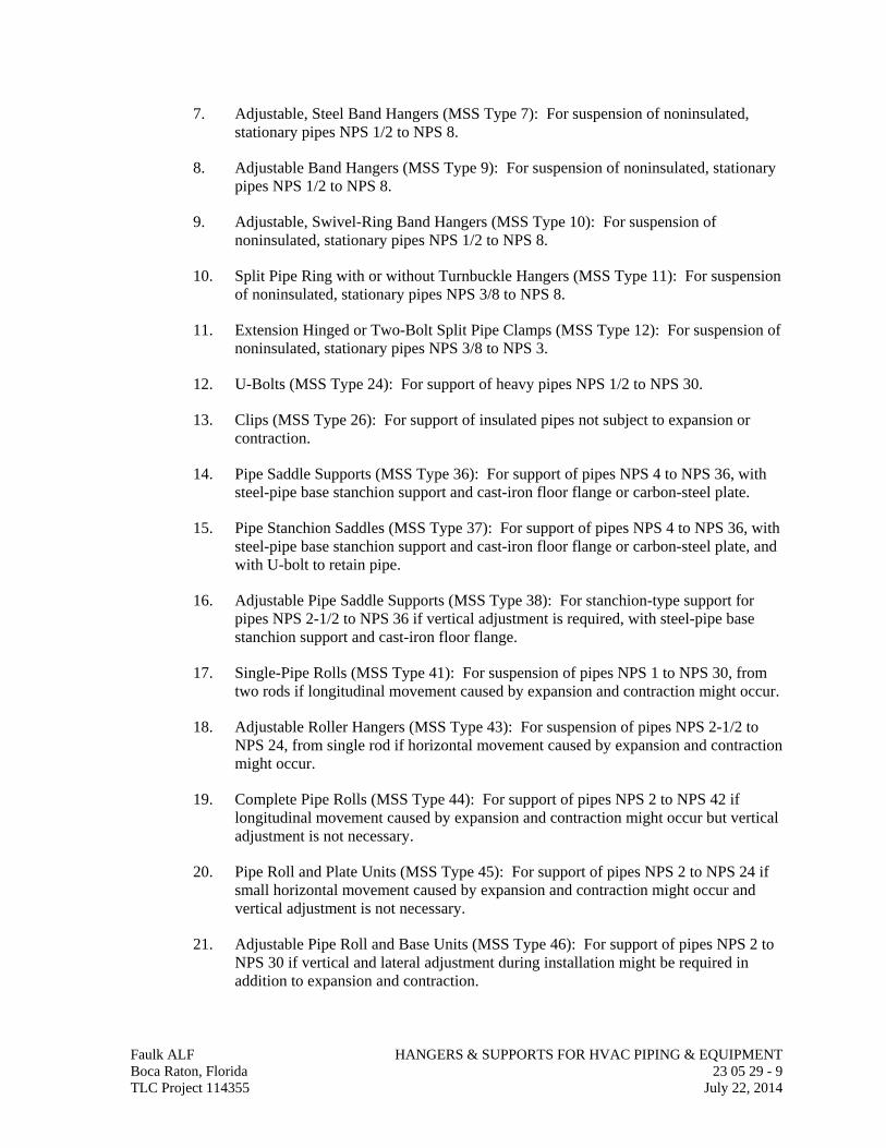
7. Adjustable, Steel Band Hangers (MSS Type 7): For suspension of noninsulated, stationary pipes NPS 1/2 to NPS 8.
8. Adjustable Band Hangers (MSS Type 9): For suspension of noninsulated, stationary pipes NPS 1/2 to NPS 8.
9. Adjustable, Swivel-Ring Band Hangers (MSS Type 10): For suspension of noninsulated, stationary pipes NPS 1/2 to NPS 8.
10. Split Pipe Ring with or without Turnbuckle Hangers (MSS Type 11): For suspension of noninsulated, stationary pipes NPS 3/8 to NPS 8.
11. Extension Hinged or Two-Bolt Split Pipe Clamps (MSS Type 12): For suspension of noninsulated, stationary pipes NPS 3/8 to NPS 3.
12. U-Bolts (MSS Type 24): For support of heavy pipes NPS 1/2 to NPS 30.
13. Clips (MSS Type 26): For support of insulated pipes not subject to expansion or contraction.
14. Pipe Saddle Supports (MSS Type 36): For support of pipes NPS 4 to NPS 36, with steel-pipe base stanchion support and cast-iron floor flange or carbon-steel plate.
15. Pipe Stanchion Saddles (MSS Type 37): For support of pipes NPS 4 to NPS 36, with steel-pipe base stanchion support and cast-iron floor flange or carbon-steel plate, and with U-bolt to retain pipe.
16. Adjustable Pipe Saddle Supports (MSS Type 38): For stanchion-type support for pipes NPS 2-1/2 to NPS 36 if vertical adjustment is required, with steel-pipe base stanchion support and cast-iron floor flange.
17. Single-Pipe Rolls (MSS Type 41): For suspension of pipes NPS 1 to NPS 30, from two rods if longitudinal movement caused by expansion and contraction might occur.
18. Adjustable Roller Hangers (MSS Type 43): For suspension of pipes NPS 2-1/2 to NPS 24, from single rod if horizontal movement caused by expansion and contraction might occur.
19. Complete Pipe Rolls (MSS Type 44): For support of pipes NPS 2 to NPS 42 if longitudinal movement caused by expansion and contraction might occur but vertical adjustment is not necessary.
20. Pipe Roll and Plate Units (MSS Type 45): For support of pipes NPS 2 to NPS 24 if small horizontal movement caused by expansion and contraction might occur and vertical adjustment is not necessary.
21. Adjustable Pipe Roll and Base Units (MSS Type 46): For support of pipes NPS 2 to NPS 30 if vertical and lateral adjustment during installation might be required in addition to expansion and contraction.
Faulk ALF HANGERS & SUPPORTS FOR HVAC PIPING & EQUIPMENT Boca Raton, Florida 23 05 29 - 9 TLC Project 114355 July 22, 2014
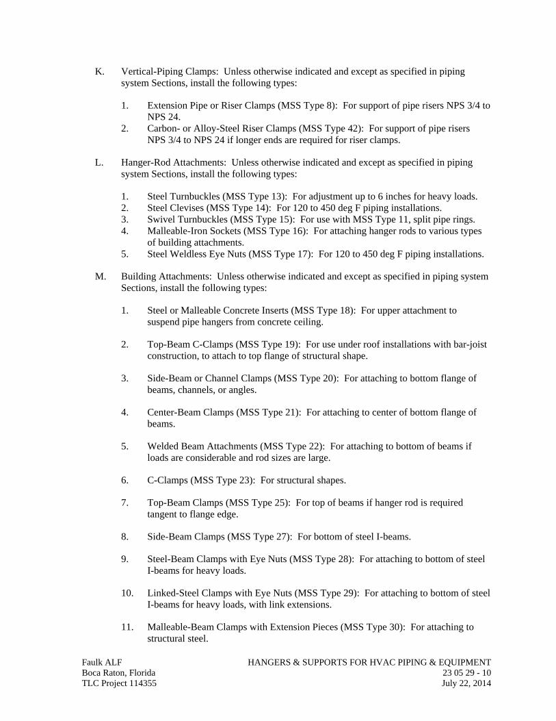
K. Vertical-Piping Clamps: Unless otherwise indicated and except as specified in piping system Sections, install the following types:
1. Extension Pipe or Riser Clamps (MSS Type 8): For support of pipe risers NPS 3/4 to NPS 24.
2. Carbon- or Alloy-Steel Riser Clamps (MSS Type 42): For support of pipe risers NPS 3/4 to NPS 24 if longer ends are required for riser clamps.
L. Hanger-Rod Attachments: Unless otherwise indicated and except as specified in piping system Sections, install the following types:
1. Steel Turnbuckles (MSS Type 13): For adjustment up to 6 inches for heavy loads. 2. Steel Clevises (MSS Type 14): For 120 to 450 deg F piping installations. 3. Swivel Turnbuckles (MSS Type 15): For use with MSS Type 11, split pipe rings. 4. Malleable-Iron Sockets (MSS Type 16): For attaching hanger rods to various types
of building attachments. 5. Steel Weldless Eye Nuts (MSS Type 17): For 120 to 450 deg F piping installations.
M. Building Attachments: Unless otherwise indicated and except as specified in piping system Sections, install the following types:
1. Steel or Malleable Concrete Inserts (MSS Type 18): For upper attachment to suspend pipe hangers from concrete ceiling.
2. Top-Beam C-Clamps (MSS Type 19): For use under roof installations with bar-joist construction, to attach to top flange of structural shape.
3. Side-Beam or Channel Clamps (MSS Type 20): For attaching to bottom flange of beams, channels, or angles.
4. Center-Beam Clamps (MSS Type 21): For attaching to center of bottom flange of beams.
5. Welded Beam Attachments (MSS Type 22): For attaching to bottom of beams if loads are considerable and rod sizes are large.
6. C-Clamps (MSS Type 23): For structural shapes.
7. Top-Beam Clamps (MSS Type 25): For top of beams if hanger rod is required tangent to flange edge.
8. Side-Beam Clamps (MSS Type 27): For bottom of steel I-beams.
9. Steel-Beam Clamps with Eye Nuts (MSS Type 28): For attaching to bottom of steel I-beams for heavy loads.
10. Linked-Steel Clamps with Eye Nuts (MSS Type 29): For attaching to bottom of steel I-beams for heavy loads, with link extensions.
11. Malleable-Beam Clamps with Extension Pieces (MSS Type 30): For attaching to structural steel.
Faulk ALF HANGERS & SUPPORTS FOR HVAC PIPING & EQUIPMENT Boca Raton, Florida 23 05 29 - 10 TLC Project 114355 July 22, 2014
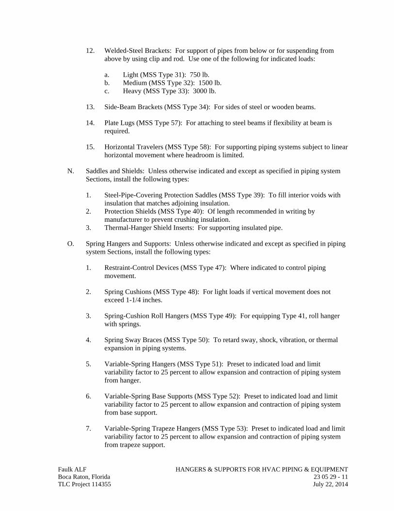
12. Welded-Steel Brackets: For support of pipes from below or for suspending from above by using clip and rod. Use one of the following for indicated loads:
a. Light (MSS Type 31): 750 lb. b. Medium (MSS Type 32): 1500 lb. c. Heavy (MSS Type 33): 3000 lb.
13. Side-Beam Brackets (MSS Type 34): For sides of steel or wooden beams.
14. Plate Lugs (MSS Type 57): For attaching to steel beams if flexibility at beam is required.
15. Horizontal Travelers (MSS Type 58): For supporting piping systems subject to linear horizontal movement where headroom is limited.
N. Saddles and Shields: Unless otherwise indicated and except as specified in piping system Sections, install the following types:
1. Steel-Pipe-Covering Protection Saddles (MSS Type 39): To fill interior voids with insulation that matches adjoining insulation.
2. Protection Shields (MSS Type 40): Of length recommended in writing by manufacturer to prevent crushing insulation.
3. Thermal-Hanger Shield Inserts: For supporting insulated pipe.
O. Spring Hangers and Supports: Unless otherwise indicated and except as specified in piping system Sections, install the following types:
1. Restraint-Control Devices (MSS Type 47): Where indicated to control piping movement.
2. Spring Cushions (MSS Type 48): For light loads if vertical movement does not exceed 1-1/4 inches.
3. Spring-Cushion Roll Hangers (MSS Type 49): For equipping Type 41, roll hanger with springs.
4. Spring Sway Braces (MSS Type 50): To retard sway, shock, vibration, or thermal expansion in piping systems.
5. Variable-Spring Hangers (MSS Type 51): Preset to indicated load and limit variability factor to 25 percent to allow expansion and contraction of piping system from hanger.
6. Variable-Spring Base Supports (MSS Type 52): Preset to indicated load and limit variability factor to 25 percent to allow expansion and contraction of piping system from base support.
7. Variable-Spring Trapeze Hangers (MSS Type 53): Preset to indicated load and limit variability factor to 25 percent to allow expansion and contraction of piping system from trapeze support.
Faulk ALF HANGERS & SUPPORTS FOR HVAC PIPING & EQUIPMENT Boca Raton, Florida 23 05 29 - 11 TLC Project 114355 July 22, 2014
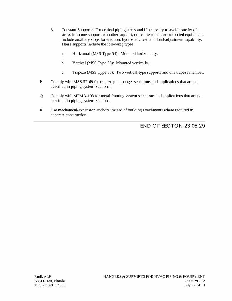
Faulk ALF HANGERS & SUPPORTS FOR HVAC PIPING & EQUIPMENT Boca Raton, Florida 23 05 29 - 12 TLC Project 114355 July 22, 2014
8. Constant Supports: For critical piping stress and if necessary to avoid transfer of stress from one support to another support, critical terminal, or connected equipment. Include auxiliary stops for erection, hydrostatic test, and load-adjustment capability. These supports include the following types:
a. Horizontal (MSS Type 54): Mounted horizontally.
b. Vertical (MSS Type 55): Mounted vertically.
c. Trapeze (MSS Type 56): Two vertical-type supports and one trapeze member.
P. Comply with MSS SP-69 for trapeze pipe-hanger selections and applications that are not specified in piping system Sections.
Q. Comply with MFMA-103 for metal framing system selections and applications that are not specified in piping system Sections.
R. Use mechanical-expansion anchors instead of building attachments where required in concrete construction.
END OF SECTION 23 05 29
SECTION 23 05 48
VIBRATION CONTROLS FOR HVAC
Faulk ALF VIBRATION & SEISMIC CONTROLS FOR HVAC Boca Raton, Florida 23 05 48 - 1 TLC Project 114355 July 22, 2014
PART 1 - GENERAL
1.01 RELATED DOCUMENTS
A. Drawings and general provisions of the Contract, including General and Supplementary Conditions and Division 01 Specification Sections, apply to this Section.
1.02 SUMMARY
A. Section Includes:
1. Elastomeric isolation pads. 2. Elastomeric isolation mounts. 3. Restrained elastomeric isolation mounts. 4. Open-spring isolators. 5. Housed-spring isolators. 6. Restrained-spring isolators. 7. Housed-restrained-spring isolators. 8. Pipe-riser resilient supports. 9. Resilient pipe guides. 10. Air-spring isolators. 11. Restrained-air-spring isolators. 12. Elastomeric hangers. 13. Spring hangers. 14. Snubbers. 15. Restraint channel bracings. 16. Restraint cables. 17. Mechanical anchor bolts. 18. Adhesive anchor bolts. 19. Vibration isolation equipment bases. 20. Restrained isolation roof-curb rails.
B. Related Requirements:
1. Section 210548 "Vibration and Seismic Controls for Fire Suppression" for devices for fire-suppression equipment and systems.
2. Section 220548 "Vibration Controls for Plumbing" for devices for plumbing equipment and systems.
1.03 DEFINITIONS
A. IBC: International Building Code.
B. ICC-ES: ICC-Evaluation Service.
1.04 ACTION SUBMITTALS
A. Product Data: For each type of product.
1. Include rated load, rated deflection, and overload capacity for each vibration isolation device.
2. Illustrate and indicate style, material, strength, fastening provision, and finish for each type and size of vibration isolation device and seismic-restraint component required.
a. Annotate to indicate application of each product submitted and compliance with requirements.
B. Shop Drawings:
1. Detail fabrication and assembly of equipment bases. Detail fabrication including anchorages and attachments to structure and to supported equipment. Include adjustable motor bases, rails, and frames for equipment mounting.
2. Vibration Isolation Base Details: Detail fabrication including anchorages and attachments to structure and to supported equipment. Include adjustable motor bases, rails, and frames for equipment mounting.
C. Delegated-Design Submittal: For each vibration isolation device.
1. Include design calculations and details for selecting vibration isolators, seismic restraints, and vibration isolation bases complying with performance requirements, design criteria, and analysis data signed and sealed by the qualified professional engineer responsible for their preparation.
2. Design Calculations: Calculate static and dynamic loading due to equipment weight, operation, and wind forces required to select vibration isolators restraints and for designing vibration isolation bases.
a. Coordinate design calculations with wind load calculations required for equipment mounted outdoors. Comply with requirements in other Sections for equipment mounted outdoors.
3. Wind Restraint Details:
a. Design Analysis: To support selection and arrangement of wind restraints. Include calculations of combined tensile and shear loads.
b. Details: Indicate fabrication and arrangement. Detail attachments of restraints to the restrained items and to the structure. Show attachment locations, methods, and spacings. Identify components, list their strengths, and indicate directions and values of forces transmitted to the structure during seismic events. Indicate association with vibration isolation devices.
c. Coordinate vibration isolation details with wind-restraint details required for equipment mounted outdoors. Comply with requirements in other Sections for equipment mounted outdoors.
Faulk ALF VIBRATION & SEISMIC CONTROLS FOR HVAC Boca Raton, Florida 23 05 48 - 2 TLC Project 114355 July 22, 2014
1.05 INFORMATIONAL SUBMITTALS
A. Coordination Drawings: Show coordination of vibration isolation device installation and seismic bracing for HVAC piping and equipment with other systems and equipment in the vicinity, including other supports and restraints, if any.
B. Qualification Data: For professional engineer.
C. Welding certificates.
D. Field quality-control reports.
1.06 CLOSEOUT SUBMITTALS
A. Operation and Maintenance Data: For air-spring mounts and restrained-air-spring mounts to include in operation and maintenance manuals.
1.07 QUALITY ASSURANCE
A. Testing Agency Qualifications: An independent agency, with the experience and capability to conduct the testing indicated, that is an NRTL as defined by OSHA in 29 CFR 1910.7 and that is acceptable to authorities having jurisdiction.
B. Welding Qualifications: Qualify procedures and personnel according to AWS D1.1/D1.1M, "Structural Welding Code - Steel."
PART 2 - PRODUCTS
2.01 PERFORMANCE REQUIREMENTS
A. Wind-Restraint Loading:
1. Basic Wind Speed: 2. Building Classification Category: 3. Minimum 10 lb/sq. ft. multiplied by maximum area of HVAC component projected
on vertical plane normal to wind direction, and 45 degrees either side of normal.
2.02 ELASTOMERIC ISOLATION PADS
A. Elastomeric Isolation Pads:
1. Manufacturers: Subject to compliance with requirements, provide products by the following:
a. Mason Industries, Inc. b. Vibration Eliminator Co., Inc. c. Vibration Isolation. d. Vibration Mountings & Controls, Inc.
2. Fabrication: Single or multiple layers of sufficient durometer stiffness for uniform loading over pad area.
3. Size: Factory or field cut to match requirements of supported equipment. Faulk ALF VIBRATION & SEISMIC CONTROLS FOR HVAC Boca Raton, Florida 23 05 48 - 3 TLC Project 114355 July 22, 2014
4. Pad Material: Oil and water resistant with elastomeric properties. 5. Surface Pattern: Smooth, ribbed or waffle pattern. 6. Infused nonwoven cotton or synthetic fibers. 7. Load-bearing metal plates adhered to pads.
8. Sandwich-Core Material: Resilient and elastomeric.
a. Surface Pattern: Smooth, ribbed or Waffle pattern. b. Infused nonwoven cotton or synthetic fibers.
2.03 ELASTOMERIC ISOLATION MOUNTS
A. Mounting Plates:
a. Top Plate: Encapsulated steel load transfer top plates, factory drilled and threaded with threaded studs or bolts.
b. Baseplate: Encapsulated steel bottom plates with holes provided for anchoring to support structure.
2. Elastomeric Material: Molded, oil-resistant rubber, neoprene, or other elastomeric material.
2.04 RESTRAINED ELASTOMERIC ISOLATION MOUNTS
A. Restrained Elastomeric Isolation Mounts:
1. Manufacturers: Subject to compliance with requirements, provide products by one of the following:
a. Ace Mountings Co., Inc. b. California Dynamics Corporation. c. Isolation Technology, Inc. d. Kinetics Noise Control, Inc. e. Mason Industries, Inc. f. Vibration Eliminator Co., Inc. g. Vibration Isolation. h. Vibration Mountings & Controls, Inc.
2. Description: All-directional isolator with seismic restraints containing two separate and opposing elastomeric elements that prevent central threaded element and attachment hardware from contacting the housing during normal operation.
a. Housing: Cast-ductile iron or welded steel. b. Elastomeric Material: Molded, oil-resistant rubber, neoprene, or other
elastomeric material.
2.05 OPEN-SPRING ISOLATORS
A. Freestanding, Laterally Stable, Open-Spring Isolators:
Faulk ALF VIBRATION & SEISMIC CONTROLS FOR HVAC Boca Raton, Florida 23 05 48 - 4 TLC Project 114355 July 22, 2014
1. Manufacturers: Subject to compliance with requirements, provide products by one of the following:
a. Mason Industries, Inc. b. Vibration Eliminator Co., Inc. c. Vibration Isolation. d. Vibration Mountings & Controls, Inc.
2. Outside Spring Diameter: Not less than 80 percent of the compressed height of the spring at rated load.
3. Minimum Additional Travel: 50 percent of the required deflection at rated load. 4. Lateral Stiffness: More than 80 percent of rated vertical stiffness. 5. Overload Capacity: Support 200 percent of rated load, fully compressed, without
deformation or failure. 6. Baseplates: Factory-drilled steel plate for bolting to structure with an elastomeric
isolator pad attached to the underside. Baseplates shall limit floor load to 500 psig. 7. Top Plate and Adjustment Bolt: Threaded top plate with adjustment bolt and cap
screw to fasten and level equipment.
2.06 HOUSED-SPRING ISOLATORS
A. Freestanding, Laterally Stable, Open-Spring Isolators in Two-Part Telescoping Housing:
1. Manufacturers: Subject to compliance with requirements, provide products by one of the following:
a. Mason Industries, Inc. b. Vibration Eliminator Co., Inc. c. Vibration Isolation. d. Vibration Mountings & Controls, Inc.
2. Outside Spring Diameter: Not less than 80 percent of the compressed height of the spring at rated load.
3. Minimum Additional Travel: 50 percent of the required deflection at rated load. 4. Lateral Stiffness: More than 80 percent of rated vertical stiffness. 5. Overload Capacity: Support 200 percent of rated load, fully compressed, without
deformation or failure.
6. Two-Part Telescoping Housing: A steel top and bottom frame separated by an elastomeric material and enclosing the spring isolators.
a. Drilled base housing for bolting to structure with an elastomeric isolator pad attached to the underside. Bases shall limit floor load to 500 psig.
b. Top housing with elastomeric pad.
2.07 RESTRAINED-SPRING ISOLATORS
A. Freestanding, Laterally Stable, Open-Spring Isolators with Vertical-Limit Stop Restraint:
Faulk ALF VIBRATION & SEISMIC CONTROLS FOR HVAC Boca Raton, Florida 23 05 48 - 5 TLC Project 114355 July 22, 2014
1. Manufacturers: Subject to compliance with requirements, provide products by one of the following:
a. Mason Industries, Inc. b. Vibration Eliminator Co., Inc. c. Vibration Isolation. d. Vibration Mountings & Controls, Inc.
2. Housing: Steel housing with vertical-limit stops to prevent spring extension due to weight being removed.
a. Base with holes for bolting to structure with an elastomeric isolator pad attached to the underside. Bases shall limit floor load to 500 psig.
b. Top plate with elastomeric pad. c. Internal leveling bolt that acts as blocking during installation.
3. Restraint: Limit stop as required for equipment and authorities having jurisdiction. 4. Outside Spring Diameter: Not less than 80 percent of the compressed height of the
spring at rated load. 5. Minimum Additional Travel: 50 percent of the required deflection at rated load. 6. Lateral Stiffness: More than 80 percent of rated vertical stiffness. 7. Overload Capacity: Support 200 percent of rated load, fully compressed, without
deformation or failure.
2.08 HOUSED-RESTRAINED-SPRING ISOLATORS
A. Freestanding, Steel, Open-Spring Isolators with Vertical-Limit Stop Restraint in Two-Part Telescoping Housing:
1. Manufacturers: Subject to compliance with requirements, provide products by one of the following:
a. Mason Industries, Inc. b. Vibration Eliminator Co., Inc. c. Vibration Isolation. d. Vibration Mountings & Controls, Inc.
2. Two-Part Telescoping Housing: A steel top and bottom frame separated by an elastomeric material and enclosing the spring isolators. Housings are equipped with non-adjustable snubbers to limit vertical movement.
a. Drilled base housing for bolting to structure with an elastomeric isolator pad attached to the underside. Bases shall limit floor load to 500 psig.
b. Threaded top housing with adjustment bolt and cap screw to fasten and level equipment.
3. Outside Spring Diameter: Not less than 80 percent of the compressed height of the spring at rated load.
4. Minimum Additional Travel: 50 percent of the required deflection at rated load. 5. Lateral Stiffness: More than 80 percent of rated vertical stiffness.
Faulk ALF VIBRATION & SEISMIC CONTROLS FOR HVAC Boca Raton, Florida 23 05 48 - 6 TLC Project 114355 July 22, 2014
6. Overload Capacity: Support 200 percent of rated load, fully compressed, without deformation or failure.
2.09 ELASTOMERIC HANGERS
A. Elastomeric Mount in a Steel Frame with Upper and Lower Steel Hanger Rods:
1. Manufacturers: Subject to compliance with requirements, provide products by one of the following: a. Mason Industries, Inc. b. Vibration Eliminator Co., Inc. c. Vibration Mountings & Controls, Inc.
2. Frame: Steel, fabricated with a connection for an upper threaded hanger rod and an opening on the underside to allow for a maximum of 30 degrees of angular lower hanger-rod misalignment without binding or reducing isolation efficiency.
3. Dampening Element: Molded, oil-resistant rubber, neoprene, or other elastomeric material with a projecting bushing for the underside opening preventing steel to steel contact.
2.10 SPRING HANGERS
A. Combination Coil-Spring and Elastomeric-Insert Hanger with Spring and Insert in Compression:
1. Manufacturers: Subject to compliance with requirements, provide products by one of the following:
a. Mason Industries, Inc. b. Vibration Eliminator Co., Inc. c. Vibration Isolation. d. Vibration Mountings & Controls, Inc.
2. Frame: Steel, fabricated for connection to threaded hanger rods and to allow for a maximum of 30 degrees of angular hanger-rod misalignment without binding or reducing isolation efficiency.
3. Outside Spring Diameter: Not less than 80 percent of the compressed height of the spring at rated load.
4. Minimum Additional Travel: 50 percent of the required deflection at rated load. 5. Lateral Stiffness: More than 80 percent of rated vertical stiffness. 6. Overload Capacity: Support 200 percent of rated load, fully compressed, without
deformation or failure. 7. Elastomeric Element: Molded, oil-resistant rubber or neoprene. Steel-washer-
reinforced cup to support spring and bushing projecting through bottom of frame. 8. Adjustable Vertical Stop: Steel washer with neoprene washer "up-stop" on lower
threaded rod. 9. Self-centering hanger-rod cap to ensure concentricity between hanger rod and
support spring coil.
Faulk ALF VIBRATION & SEISMIC CONTROLS FOR HVAC Boca Raton, Florida 23 05 48 - 7 TLC Project 114355 July 22, 2014
2.11 SNUBBERS
A. Manufacturers: Subject to compliance with requirements, provide products by one of the following:
1. Kinetics Noise Control, Inc. 2. Mason Industries, Inc. 3. Vibration Mountings & Controls, Inc.
B. Description: Factory fabricated using welded structural-steel shapes and plates, anchor bolts, and replaceable resilient isolation washers and bushings.
1. Anchor bolts for attaching to concrete shall be seismic-rated, drill-in, and stud-wedge or female-wedge type.
2. Resilient Isolation Washers and Bushings: Oil- and water-resistant neoprene. 3. Maximum 1/4-inch air gap, and minimum 1/4-inch- thick resilient cushion.
2.12 MECHANICAL ANCHOR BOLTS
A. Manufacturers: Subject to compliance with requirements, provide products by one of the following:
1. Cooper B-Line, Inc. 2. Hilti, Inc. 3. Kinetics Noise Control, Inc. 4. Mason Industries, Inc.
B. Mechanical Anchor Bolts: Drilled-in and stud-wedge or female-wedge type in zinc-coated steel for interior applications and stainless steel for exterior applications. Select anchor bolts with strength required for anchor and as tested according to ASTM E 488.
2.13 ADHESIVE ANCHOR BOLTS
A. Manufacturers: Subject to compliance with requirements, provide products by one of the following:
1. Hilti, Inc. 2. Kinetics Noise Control, Inc. 3. Mason Industries, Inc.
B. Adhesive Anchor Bolts: Drilled-in and capsule anchor system containing PVC or urethane methacrylate-based resin and accelerator, or injected polymer or hybrid mortar adhesive. Provide anchor bolts and hardware with zinc-coated steel for interior applications and stainless steel for exterior applications. Select anchor bolts with strength required for anchor and as tested according to ASTM E 488.
2.14 RESTRAINED ISOLATION ROOF-CURB RAILS
A. Manufacturers: Subject to compliance with requirements, provide products by one of the following:
Faulk ALF VIBRATION & SEISMIC CONTROLS FOR HVAC Boca Raton, Florida 23 05 48 - 8 TLC Project 114355 July 22, 2014
1. Ace Mountings Co., Inc. 2. California Dynamics Corporation. 3. Kinetics Noise Control. 4. Mason Industries, Inc. 5. Thybar Corporation.
B. Description: Factory-assembled, fully enclosed, insulated, air- and watertight curb rail designed to resiliently support equipment and to withstand wind forces.
C. Upper Frame: The upper frame shall provide continuous support for equipment and shall be captive to resiliently resist wind forces.
D. Lower Support Assembly: The lower support assembly shall be formed sheet metal section containing adjustable and removable steel springs that support the upper frame. The lower support assembly shall have a means for attaching to building structure and a wood nailer for attaching roof materials, and shall be insulated with a minimum of 2 inches of rigid, glass-fiber insulation on inside of assembly. Adjustable, restrained-spring isolators shall be mounted on elastomeric vibration isolation pads and shall have access ports, for level adjustment, with removable waterproof covers at all isolator locations. Isolators shall be located so they are accessible for adjustment at any time during the life of the installation without interfering with the integrity of the roof.
E. Snubber Bushings: All-directional, elastomeric snubber bushings at least 1/4 inch thick.
F. Water Seal: Galvanized sheet metal with EPDM seals at corners, attached to upper support frame, extending down past wood nailer of lower support assembly, and counterflashed over roof materials.
PART 3 - EXECUTION
3.01 EXAMINATION
A. Examine areas and equipment to receive vibration isolation and wind control devices for compliance with requirements for installation tolerances and other conditions affecting performance of the Work.
B. Examine roughing-in of reinforcement and cast-in-place anchors to verify actual locations before installation.
C. Proceed with installation only after unsatisfactory conditions have been corrected.
3.02 APPLICATIONS
A. Multiple Pipe Supports: Secure pipes to trapeze member with clamps approved for application by an agency acceptable to authorities having jurisdiction.
B. Hanger-Rod Stiffeners: Install hanger-rod stiffeners where indicated or scheduled on Drawings to receive them and where required to prevent buckling of hanger rods due to seismic forces.
Faulk ALF VIBRATION & SEISMIC CONTROLS FOR HVAC Boca Raton, Florida 23 05 48 - 9 TLC Project 114355 July 22, 2014
C. Strength of Support and Seismic-Restraint Assemblies: Where not indicated, select sizes of components so strength is adequate to carry present and future static and seismic loads within specified loading limits.
3.03 VIBRATION CONTROL DEVICE INSTALLATION
A. Coordinate the location of embedded connection hardware with supported equipment attachment and mounting points and with requirements for concrete reinforcement and formwork specified in Section 033053 "Miscellaneous Cast-in-Place Concrete."
B. Installation of vibration isolators must not cause any change of position of equipment, piping, or ductwork resulting in stresses or misalignment.
C. Comply with requirements in Section 077200 "Roof Accessories" for installation of roof curbs, equipment supports, and roof penetrations.
D. Equipment Restraints:
1. Install seismic snubbers on HVAC equipment mounted on vibration isolators. Locate snubbers as close as possible to vibration isolators and bolt to equipment base and supporting structure.
2. Install resilient bolt isolation washers on equipment anchor bolts where clearance between anchor and adjacent surface exceeds 0.125 inch.
3. Install seismic-restraint devices using methods approved by an agency acceptable to authorities having jurisdiction that provides required submittals for component.
E. Piping Restraints:
1. Comply with requirements in MSS SP-127. 2. Space lateral supports a maximum of 40 feet o.c., and longitudinal supports a
maximum of 80 feet o.c. 3. Brace a change of direction longer than 12 feet.
F. Install cables so they do not bend across edges of adjacent equipment or building structure.
G. Install seismic-restraint devices using methods approved by an agency acceptable to authorities having jurisdiction that provides required submittals for component.
H. Install bushing assemblies for anchor bolts for floor-mounted equipment, arranged to provide resilient media between anchor bolt and mounting hole in concrete base.
I. Install bushing assemblies for mounting bolts for wall-mounted equipment, arranged to provide resilient media where equipment or equipment-mounting channels are attached to wall.
J. Attachment to Structure: If specific attachment is not indicated, anchor bracing to structure at flanges of beams, at upper truss chords of bar joists, or at concrete members.
K. Drilled-in Anchors:
Faulk ALF VIBRATION & SEISMIC CONTROLS FOR HVAC Boca Raton, Florida 23 05 48 - 10 TLC Project 114355 July 22, 2014
1. Identify position of reinforcing steel and other embedded items prior to drilling holes for anchors. Do not damage existing reinforcing or embedded items during coring or drilling. Notify the structural engineer if reinforcing steel or other embedded items are encountered during drilling. Locate and avoid prestressed tendons, electrical and telecommunications conduit, and gas lines.
2. Do not drill holes in concrete or masonry until concrete, mortar, or grout has achieved full design strength.
3. Wedge Anchors: Protect threads from damage during anchor installation. Heavy-duty sleeve anchors shall be installed with sleeve fully engaged in the structural element to which anchor is to be fastened.
4. Adhesive Anchors: Clean holes to remove loose material and drilling dust prior to installation of adhesive. Place adhesive in holes proceeding from the bottom of the hole and progressing toward the surface in such a manner as to avoid introduction of air pockets in the adhesive.
5. Set anchors to manufacturer's recommended torque, using a torque wrench.
6. Install zinc-coated steel anchors for interior and stainless-steel anchors for exterior applications.
3.04 FIELD QUALITY CONTROL
A. Testing Agency: Owner will engage a qualified testing agency to perform tests and inspections.
B. Perform tests and inspections.
C. Tests and Inspections:
1. Provide evidence of recent calibration of test equipment by a testing agency acceptable to authorities having jurisdiction.
2. Schedule test with Owner, through Architect, before connecting anchorage device to restrained component (unless post-connection testing has been approved), and with at least seven days' advance notice.
3. Obtain Architect's approval before transmitting test loads to structure. Provide temporary load-spreading members.
4. Test at least four of each type and size of installed anchors and fasteners selected by Architect.
5. Test to 90 percent of rated proof load of device. 6. Measure isolator restraint clearance. 7. Measure isolator deflection. 8. Verify snubber minimum clearances. 9. Test and adjust restrained-air-spring isolator controls and safeties.
D. Remove and replace malfunctioning units and retest as specified above.
E. Prepare test and inspection reports.
Faulk ALF VIBRATION & SEISMIC CONTROLS FOR HVAC Boca Raton, Florida 23 05 48 - 11 TLC Project 114355 July 22, 2014
Faulk ALF VIBRATION & SEISMIC CONTROLS FOR HVAC Boca Raton, Florida 23 05 48 - 12 TLC Project 114355 July 22, 2014
3.05 ADJUSTING
A. Adjust isolators after piping system is at operating weight.
B. Adjust limit stops on restrained-spring isolators to mount equipment at normal operating height. After equipment installation is complete, adjust limit stops so they are out of contact during normal operation.
END OF SECTION 23 05 48
SECTION 23 05 53
IDENTIFICATION FOR HVAC PIPING AND EQUIPMENT
Faulk ALF IDENTIFICATION FOR HVAC PIPING & EQUIPMENT Boca Raton, Florida 23 05 53 - 1 TLC Project 114355 July 22, 2014
PART 1 - GENERAL
1.01 RELATED DOCUMENTS
A. Drawings and general provisions of the Contract, including General and Supplementary Conditions and Division 01 Specification Sections, apply to this Section.
1.02 SUMMARY
A. Section Includes: 1. Equipment labels. 2. Warning signs and labels. 3. Pipe labels. 4. Duct labels. 5. Stencils. 6. Valve tags. 7. Warning tags.
1.03 ACTION SUBMITTALS
A. Product Data: For each type of product indicated.
B. Samples: For color, letter style, and graphic representation required for each identification material and device.
C. Equipment Label Schedule: Include a listing of all equipment to be labeled with the proposed content for each label.
D. Valve numbering scheme.
E. Valve Schedules: For each piping system to include in maintenance manuals.
1.04 COORDINATION
A. Coordinate installation of identifying devices with completion of covering and painting of surfaces where devices are to be applied.
B. Coordinate installation of identifying devices with locations of access panels and doors.
C. Install identifying devices before installing acoustical ceilings and similar concealment.
PART 2 - PRODUCTS
2.01 EQUIPMENT LABELS
A. Metal Labels for Equipment: 1. Material and Thickness: Brass, 0.032-inch , Stainless steel, 0.025-inch or anodized
aluminum, 0.032-inch minimum thickness, and having predrilled or stamped holes for attachment hardware.
2. Minimum Label Size: Length and width vary for required label content, but not less than 2-1/2 by 3/4 inch.
3. Minimum Letter Size: 1/4 inch for name of units if viewing distance is less than 24 inches, 1/2 inch for viewing distances up to 72 inches, and proportionately larger lettering for greater viewing distances. Include secondary lettering two-thirds to three-fourths the size of principal lettering.
4. Fasteners: Stainless-steel rivets or self-tapping screws. 5. Adhesive: Contact-type permanent adhesive, compatible with label and with
substrate.
B. Plastic Labels for Equipment:
1. Material and Thickness: Multilayer, multicolor, plastic labels for mechanical engraving, 1/8 inch thick, and having predrilled holes for attachment hardware.
2. Letter Color: White 3. Background Color: Black 4. Maximum Temperature: Able to withstand temperatures up to 160 deg F. 5. Minimum Label Size: Length and width vary for required label content, but not less
than 2-1/2 by 3/4 inch. 6. Minimum Letter Size: 1/4 inch for name of units if viewing distance is less than 24
inches, 1/2 inch for viewing distances up to 72 inches, and proportionately larger lettering for greater viewing distances. Include secondary lettering two-thirds to three-fourths the size of principal lettering.
7. Fasteners: Stainless-steel rivets or self-tapping screws. 8. Adhesive: Contact-type permanent adhesive, compatible with label and with
substrate.
C. Label Content: Include equipment's Drawing designation or unique equipment number, Drawing numbers where equipment is indicated (plans, details, and schedules), plus the Specification Section number and title where equipment is specified.
D. Equipment Label Schedule: For each item of equipment to be labeled, on 8-1/2-by-11-inch bond paper. Tabulate equipment identification number and identify Drawing numbers where equipment is indicated (plans, details, and schedules), plus the Specification Section number and title where equipment is specified. Equipment schedule shall be included in operation and maintenance data.
2.02 WARNING SIGNS AND LABELS
A. Material and Thickness: Multilayer, multicolor, plastic labels for mechanical engraving, 1/8 inch thick, and having predrilled holes for attachment hardware.
B. Letter Color: White
C. Background Color: Red
D. Maximum Temperature: Able to withstand temperatures up to 160 deg F.
E. Minimum Label Size: Length and width vary for required label content, but not less than 2-1/2 by 3/4 inch.
Faulk ALF IDENTIFICATION FOR HVAC PIPING & EQUIPMENT Boca Raton, Florida 23 05 53 - 2 TLC Project 114355 July 22, 2014
F. Minimum Letter Size: 1/4 inch for name of units if viewing distance is less than 24 inches, 1/2 inch for viewing distances up to 72 inches, and proportionately larger lettering for greater viewing distances. Include secondary lettering two-thirds to three-fourths the size of principal lettering.
G. Fasteners: Stainless-steel rivets or self-tapping screws .
H. Adhesive: Contact-type permanent adhesive, compatible with label and with substrate.
I. Label Content: Include caution and warning information, plus emergency notification instructions.
2.03 PIPE LABELS
A. General Requirements for Manufactured Pipe Labels: Preprinted, color-coded, with lettering indicating service, and showing flow direction.
B. Pre-tensioned Pipe Labels: Pre-coiled, semi-rigid plastic formed to cover full circumference of pipe and to attach to pipe without fasteners or adhesive.
C. Self-Adhesive Pipe Labels: Printed plastic with contact-type, permanent-adhesive backing.
D. Pipe Label Contents: Include identification of piping service using same designations or abbreviations as used on Drawings, pipe size, and an arrow indicating flow direction.
1. Flow-Direction Arrows: Integral with piping system service lettering to accommodate both directions or as separate unit on each pipe label to indicate flow direction.
2. Lettering Size: At least 1-1/2 inches high.
2.04 STENCILS
A. Stencils: Prepared with letter sizes according to ASME A13.1 for piping; minimum letter height of 1-1/4 inches for ducts; and minimum letter height of 3/4 inch for access panel and door labels, equipment labels, and similar operational instructions.
1. Stencil Material: Aluminum, Brass, Fiberboard or metal. 2. Stencil Paint: Exterior, gloss, alkyd enamel or acrylic enamel (as appropriate for the
material being painted) , black unless otherwise indicated. Paint may be in pressurized spray-can form.
3. Identification Paint: Exterior, alkyd enamel or acrylic enamel in colors according to ASME A13.1 unless otherwise indicated.
2.05 VALVE TAGS
A. Valve Tags: Stamped or engraved with 1/4-inch letters for piping system abbreviation and 1/2-inch numbers.
1. Tag Material: Brass, 0.032-inch , Stainless steel, 0.025-inch or anodized aluminum, 0.032-inch minimum thickness, and having predrilled or stamped holes for attachment hardware.
Faulk ALF IDENTIFICATION FOR HVAC PIPING & EQUIPMENT Boca Raton, Florida 23 05 53 - 3 TLC Project 114355 July 22, 2014
2. Fasteners: Brass wire-link or beaded chain; or S-hook.
B. Valve Schedules: For each piping system, on 8-1/2-by-11-inch bond paper. Tabulate valve number, piping system, system abbreviation (as shown on valve tag), location of valve (room or space), normal-operating position (open, closed, or modulating), and variations for identification. Mark valves for emergency shutoff and similar special uses.
1. Valve-tag schedule shall be included in operation and maintenance data.
2.06 WARNING TAGS
A. Warning Tags: Preprinted or partially preprinted, accident-prevention tags, of plasticized card stock with matte finish suitable for writing.
1. Size: 3 by 5-1/4 inches minimum Approximately 4 by 7 inches. 2. Fasteners: Brass grommet and wire. 3. Nomenclature: Large-size primary caption such as "DANGER," "CAUTION," or
"DO NOT OPERATE." 4. Color: Yellow background with black lettering.
PART 3 - EXECUTION
3.01 PREPARATION
A. Clean piping and equipment surfaces of substances that could impair bond of identification devices, including dirt, oil, grease, release agents, and incompatible primers, paints, and encapsulants.
3.02 EQUIPMENT LABEL INSTALLATION
A. Install or permanently fasten labels on each major item of mechanical equipment.
B. Locate equipment labels where accessible and visible.
3.03 PIPE LABEL INSTALLATION
A. Painting:
1. General: Paint all exposed piping, insulation, equipment, structural bases, racks, in equipment rooms and on roof, furnished under Division 23 of these specifications. All exposed metal surfaces shall be given one prime coat and two finished coats. All insulated surfaces shall be given one coat of glue sizing (omit this step if factory applied finish is suitable to receive prime coat), one prime coat and one finish coat. Factory painted or finished items do not require field painting but shall require “touch-up” with matching paint or finish where scratched. Follow manufacturer’s recommendations on ambient conditions for painting, coat thickness and drying time between coats.
2. Ancillary Items: Pipe hangers, saddles, supports, riser clamps and accessories shall be painted to match their piping.
Faulk ALF IDENTIFICATION FOR HVAC PIPING & EQUIPMENT Boca Raton, Florida 23 05 53 - 4 TLC Project 114355 July 22, 2014
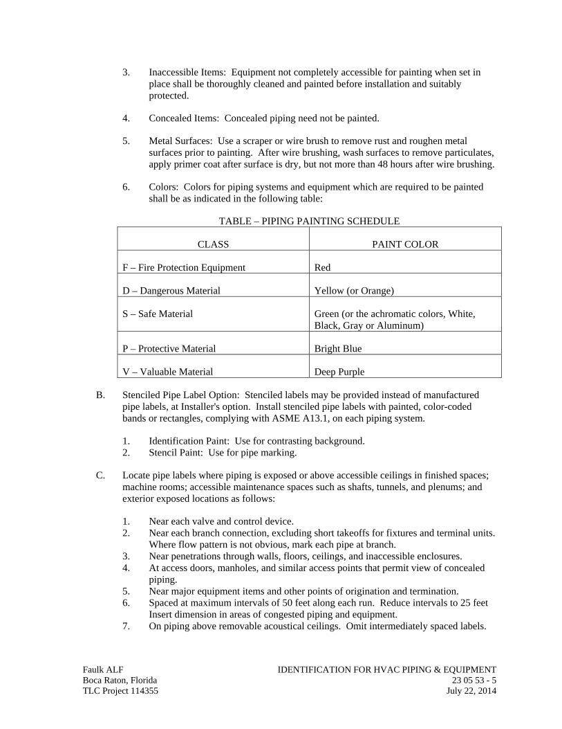
3. Inaccessible Items: Equipment not completely accessible for painting when set in place shall be thoroughly cleaned and painted before installation and suitably protected.
4. Concealed Items: Concealed piping need not be painted.
5. Metal Surfaces: Use a scraper or wire brush to remove rust and roughen metal surfaces prior to painting. After wire brushing, wash surfaces to remove particulates, apply primer coat after surface is dry, but not more than 48 hours after wire brushing.
6. Colors: Colors for piping systems and equipment which are required to be painted shall be as indicated in the following table:
TABLE – PIPING PAINTING SCHEDULE
CLASS PAINT COLOR
F – Fire Protection Equipment Red
D – Dangerous Material Yellow (or Orange)
S – Safe Material Green (or the achromatic colors, White, Black, Gray or Aluminum)
P – Protective Material Bright Blue
V – Valuable Material Deep Purple
B. Stenciled Pipe Label Option: Stenciled labels may be provided instead of manufactured pipe labels, at Installer's option. Install stenciled pipe labels with painted, color-coded bands or rectangles, complying with ASME A13.1, on each piping system.
1. Identification Paint: Use for contrasting background. 2. Stencil Paint: Use for pipe marking.
C. Locate pipe labels where piping is exposed or above accessible ceilings in finished spaces; machine rooms; accessible maintenance spaces such as shafts, tunnels, and plenums; and exterior exposed locations as follows:
1. Near each valve and control device. 2. Near each branch connection, excluding short takeoffs for fixtures and terminal units.
Where flow pattern is not obvious, mark each pipe at branch. 3. Near penetrations through walls, floors, ceilings, and inaccessible enclosures. 4. At access doors, manholes, and similar access points that permit view of concealed
piping. 5. Near major equipment items and other points of origination and termination. 6. Spaced at maximum intervals of 50 feet along each run. Reduce intervals to 25 feet
Insert dimension in areas of congested piping and equipment. 7. On piping above removable acoustical ceilings. Omit intermediately spaced labels.
Faulk ALF IDENTIFICATION FOR HVAC PIPING & EQUIPMENT Boca Raton, Florida 23 05 53 - 5 TLC Project 114355 July 22, 2014
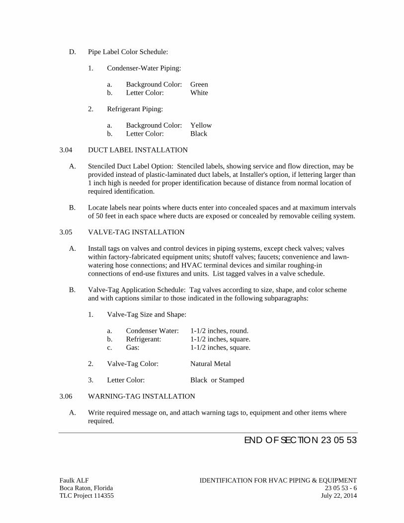
Faulk ALF IDENTIFICATION FOR HVAC PIPING & EQUIPMENT Boca Raton, Florida 23 05 53 - 6 TLC Project 114355 July 22, 2014
D. Pipe Label Color Schedule:
1. Condenser-Water Piping:
a. Background Color: Green b. Letter Color: White
2. Refrigerant Piping:
a. Background Color: Yellow b. Letter Color: Black
3.04 DUCT LABEL INSTALLATION
A. Stenciled Duct Label Option: Stenciled labels, showing service and flow direction, may be provided instead of plastic-laminated duct labels, at Installer's option, if lettering larger than 1 inch high is needed for proper identification because of distance from normal location of required identification.
B. Locate labels near points where ducts enter into concealed spaces and at maximum intervals of 50 feet in each space where ducts are exposed or concealed by removable ceiling system.
3.05 VALVE-TAG INSTALLATION
A. Install tags on valves and control devices in piping systems, except check valves; valves within factory-fabricated equipment units; shutoff valves; faucets; convenience and lawn-watering hose connections; and HVAC terminal devices and similar roughing-in connections of end-use fixtures and units. List tagged valves in a valve schedule.
B. Valve-Tag Application Schedule: Tag valves according to size, shape, and color scheme and with captions similar to those indicated in the following subparagraphs:
1. Valve-Tag Size and Shape:
a. Condenser Water: 1-1/2 inches, round. b. Refrigerant: 1-1/2 inches, square. c. Gas: 1-1/2 inches, square.
2. Valve-Tag Color: Natural Metal
3. Letter Color: Black or Stamped
3.06 WARNING-TAG INSTALLATION
A. Write required message on, and attach warning tags to, equipment and other items where required.
END OF SECTION 23 05 53
SECTION 23 05 93
TESTING, ADJUSTING, & BALANCING FOR HVAC
Faulk ALF TESTING, ADJUSTING & BALANCING FOR HVAC Boca Raton, Florida 23 05 93 - 1 TLC Project 114355 July 22, 2014
PART 1 - GENERAL
1.01 RELATED DOCUMENTS
A. Drawings and general provisions of the Contract, including General and Supplementary Conditions and Division 01 Specification Sections, apply to this Section.
1.02 SUMMARY
A. Section Includes:
1. Balancing Air Systems:
a. Constant-volume air systems.
1.03 DEFINITIONS
A. AABC: Associated Air Balance Council.
B. NEBB: National Environmental Balancing Bureau.
C. TAB: Testing, adjusting, and balancing.
D. TABB: Testing, Adjusting, and Balancing Bureau.
E. TAB Specialist: An entity engaged to perform TAB Work.
1.04 INFORMATIONAL SUBMITTALS
A. Qualification Data: Within 30 days of Contractor's Notice to Proceed, submit documentation that the TAB contractor and this Project's TAB team members meet the qualifications specified in "Quality Assurance" Article.
B. Contract Documents Examination Report: Within 30 days of Contractor's Notice to Proceed, submit the Contract Documents review report as specified in Part 3.
C. Strategies and Procedures Plan: Within 60 days of Contractor's Notice to Proceed, submit TAB strategies and step-by-step procedures as specified in "Preparation" Article.
D. Certified TAB reports.
E. Sample report forms.
F. Instrument calibration reports, to include the following:
1. Instrument type and make. 2. Serial number. 3. Application. 4. Dates of use.
5. Dates of calibration.
1.05 QUALITY ASSURANCE
A. TAB Contractor Qualifications: Engage a TAB entity certified by AABC, NEBB or TABB.
1. TAB Field Supervisor: Employee of the TAB contractor and certified by AABC, NEBB or TABB.
2. TAB Technician: Employee of the TAB contractor and who is certified by AABC, NEBB or TABB as a TAB technician.
B. TAB Conference: Meet with Architect, Owner, Construction Manager or Commissioning Authority on approval of the TAB strategies and procedures plan to develop a mutual understanding of the details. Require the participation of the TAB field supervisor and technicians. Provide seven days' advance notice of scheduled meeting time and location.
1. Agenda Items:
a. The Contract Documents examination report. b. The TAB plan. c. Coordination and cooperation of trades and subcontractors. d. Coordination of documentation and communication flow.
C. Certify TAB field data reports and perform the following:
1. Review field data reports to validate accuracy of data and to prepare certified TAB reports.
2. Certify that the TAB team complied with the approved TAB plan and the procedures specified and referenced in this Specification.
D. TAB Report Forms: Use standard TAB contractor's forms approved by Architect, Owner, Construction Manager or Commissioning Authority.
E. Instrumentation Type, Quantity, Accuracy, and Calibration: As described in ASHRAE 111, Section 5, "Instrumentation."
F. ASHRAE Compliance: Applicable requirements in ASHRAE 62.1, Section 7.2.2 - "Air Balancing."
G. ASHRAE/IESNA Compliance: Applicable requirements in ASHRAE/IESNA 90.1, Section 6.7.2.3 - "System Balancing."
1.06 PROJECT CONDITIONS
A. Full Owner Occupancy: Owner will occupy the site and existing building during entire TAB period. Cooperate with Owner during TAB operations to minimize conflicts with Owner's operations.
B. Partial Owner Occupancy: Owner may occupy completed areas of building before Substantial Completion. Cooperate with Owner during TAB operations to minimize conflicts with Owner's operations.
Faulk ALF TESTING, ADJUSTING & BALANCING FOR HVAC Boca Raton, Florida 23 05 93 - 2 TLC Project 114355 July 22, 2014
1.07 COORDINATION
A. Notice: Provide seven days' advance notice for each test. Include scheduled test dates and times.
B. Perform TAB after leakage and pressure tests on water distribution systems have been satisfactorily completed.
PART 2 - PRODUCTS (Not Applicable)
PART 3 - EXECUTION
3.01 TAB SPECIALISTS
A. Subject to compliance with requirements, available TAB contractors that may be engaged.
3.02 EXAMINATION
A. Examine the Contract Documents to become familiar with Project requirements and to discover conditions in systems' designs that may preclude proper TAB of systems and equipment.
B. Examine systems for installed balancing devices, such as test ports, gage cocks, thermometer wells, flow-control devices, balancing valves and fittings, and manual volume dampers. Verify that locations of these balancing devices are accessible.
C. Examine the approved submittals for HVAC systems and equipment.
D. Examine design data including HVAC system descriptions, statements of design assumptions for environmental conditions and systems' output, and statements of philosophies and assumptions about HVAC system and equipment controls.
E. Examine ceiling plenums and underfloor air plenums used for supply, return, or relief air to verify that they meet the leakage class of connected ducts as specified in Section 233113 "Metal Ducts" and Section 233116 "Nonmetal Ducts" and are properly separated from adjacent areas. Verify that penetrations in plenum walls are sealed and fire-stopped if required.
F. Examine equipment performance data including fan and pump curves.
1. Relate performance data to Project conditions and requirements, including system effects that can create undesired or unpredicted conditions that cause reduced capacities in all or part of a system.
2. Calculate system-effect factors to reduce performance ratings of HVAC equipment when installed under conditions different from the conditions used to rate equipment performance. To calculate system effects for air systems, use tables and charts found
Faulk ALF TESTING, ADJUSTING & BALANCING FOR HVAC Boca Raton, Florida 23 05 93 - 3 TLC Project 114355 July 22, 2014
in AMCA 201, "Fans and Systems," or in SMACNA's "HVAC Systems - Duct Design." Compare results with the design data and installed conditions.
G. Examine system and equipment installations and verify that field quality-control testing, cleaning, and adjusting specified in individual Sections have been performed.
H. Examine test reports specified in individual system and equipment Sections.
I. Examine HVAC equipment and filters and verify that bearings are greased, belts are aligned and tight, and equipment with functioning controls is ready for operation.
J. Examine terminal units; such as VRF indoor units and verify that they are accessible and their controls are connected and functioning.
K. Examine strainers. Verify that startup screens are replaced by permanent screens with indicated perforations.
L. Examine heat-transfer coils for correct piping connections and for clean and straight fins.
M. Examine system pumps to ensure absence of entrained air in the suction piping.
N. Examine operating safety interlocks and controls on HVAC equipment.
O. Report deficiencies discovered before and during performance of TAB procedures. Observe and record system reactions to changes in conditions. Record default set points if different from indicated values.
3.03 PREPARATION
A. Prepare a TAB plan that includes strategies and step-by-step procedures.
B. Complete system-readiness checks and prepare reports. Verify the following:
1. Permanent electrical-power wiring is complete. 2. Hydronic systems are filled, clean, and free of air. 3. Automatic temperature-control systems are operational. 4. Equipment and duct access doors are securely closed. 5. Balance, smoke, and fire dampers are open. 6. Isolating and balancing valves are open and control valves are operational. 7. Ceilings are installed in critical areas where air-pattern adjustments are required and
access to balancing devices is provided. 8. Windows and doors can be closed so indicated conditions for system operations can
be met.
3.04 GENERAL PROCEDURES FOR TESTING AND BALANCING
A. Perform testing and balancing procedures on each system according to the procedures contained in AABC's "National Standards for Total System Balance", ASHRAE 111, NEBB's "Procedural Standards for Testing, Adjusting, and Balancing of Environmental Systems" or SMACNA's "HVAC Systems - Testing, Adjusting, and Balancing" and in this Section.
Faulk ALF TESTING, ADJUSTING & BALANCING FOR HVAC Boca Raton, Florida 23 05 93 - 4 TLC Project 114355 July 22, 2014
1. Comply with requirements in ASHRAE 62.1, Section 7.2.2 - "Air Balancing."
B. Cut insulation, ducts, pipes, and equipment cabinets for installation of test probes to the minimum extent necessary for TAB procedures.
1. After testing and balancing, patch probe holes in ducts with same material and thickness as used to construct ducts.
2. After testing and balancing, install test ports and duct access doors that comply with requirements in Section 233300 "Air Duct Accessories."
3. Install and join new insulation that matches removed materials. Restore insulation, coverings, vapor barrier, and finish according to Section 230713 "Duct Insulation," Section 230716 "HVAC Equipment Insulation," and Section 230719 "HVAC Piping Insulation."
C. Mark equipment and balancing devices, including damper-control positions, valve position indicators, fan-speed-control levers, and similar controls and devices, with paint or other suitable, permanent identification material to show final settings.
D. Take and report testing and balancing measurements in inch-pound (IP) units.
3.05 GENERAL PROCEDURES FOR BALANCING AIR SYSTEMS
A. Prepare test reports for both fans and outlets. Obtain manufacturer's outlet factors and recommended testing procedures. Crosscheck the summation of required outlet volumes with required fan volumes.
B. Prepare schematic diagrams of systems' "as-built" duct layouts.
C. For variable-air-volume systems, develop a plan to simulate diversity.
D. Determine the best locations in main and branch ducts for accurate duct-airflow measurements.
E. Check airflow patterns from the outdoor-air louvers and dampers and the return- and exhaust-air dampers through the supply-fan discharge and mixing dampers.
F. Locate start-stop and disconnect switches, electrical interlocks, and motor starters.
G. Verify that motor starters are equipped with properly sized thermal protection.
H. Check dampers for proper position to achieve desired airflow path.
I. Check for airflow blockages.
J. Check condensate drains for proper connections and functioning.
K. Check for proper sealing of air-handling-unit components.
Faulk ALF TESTING, ADJUSTING & BALANCING FOR HVAC Boca Raton, Florida 23 05 93 - 5 TLC Project 114355 July 22, 2014
L. Verify that air duct system is sealed as specified in Section 233113 "Metal Ducts."
3.06 PROCEDURES FOR CONSTANT-VOLUME AIR SYSTEMS
A. Adjust fans to deliver total indicated airflows within the maximum allowable fan speed listed by fan manufacturer.
1. Measure total airflow.
a. Where sufficient space in ducts is unavailable for Pitot-tube traverse measurements, measure airflow at terminal outlets and inlets and calculate the total airflow.
2. Measure fan static pressures as follows to determine actual static pressure:
a. Measure outlet static pressure as far downstream from the fan as practical and upstream from restrictions in ducts such as elbows and transitions.
b. Measure static pressure directly at the fan outlet or through the flexible connection.
c. Measure inlet static pressure of single-inlet fans in the inlet duct as near the fan as possible, upstream from the flexible connection, and downstream from duct restrictions.
d. Measure inlet static pressure of double-inlet fans through the wall of the plenum that houses the fan.
3. Measure static pressure across each component that makes up an air-handling unit, rooftop unit, and other air-handling and -treating equipment.
a. Report the cleanliness status of filters and the time static pressures are measured.
4. Measure static pressures entering and leaving other devices, such as sound traps, heat-recovery equipment, and air washers, under final balanced conditions.
5. Review Record Documents to determine variations in design static pressures versus actual static pressures. Calculate actual system-effect factors. Recommend adjustments to accommodate actual conditions.
6. Obtain approval from Architect and Owner for adjustment of fan speed higher or lower than indicated speed. Comply with requirements in HVAC Sections for air-handling units for adjustment of fans, belts, and pulley sizes to achieve indicated air-handling-unit performance.
7. Do not make fan-speed adjustments that result in motor overload. Consult equipment manufacturers about fan-speed safety factors. Modulate dampers and measure fan-motor amperage to ensure that no overload will occur. Measure amperage in full-cooling, full-heating, economizer, and any other operating mode to determine the maximum required brake horsepower.
Faulk ALF TESTING, ADJUSTING & BALANCING FOR HVAC Boca Raton, Florida 23 05 93 - 6 TLC Project 114355 July 22, 2014
B. Adjust volume dampers for main duct, submain ducts, and major branch ducts to indicated airflows within specified tolerances.
1. Measure airflow of submain and branch ducts.
a. Where sufficient space in submain and branch ducts is unavailable for Pitot-tube traverse measurements, measure airflow at terminal outlets and inlets and calculate the total airflow for that zone.
2. Measure static pressure at a point downstream from the balancing damper, and adjust volume dampers until the proper static pressure is achieved.
3. Remeasure each submain and branch duct after all have been adjusted. Continue to adjust submain and branch ducts to indicated airflows within specified tolerances.
C. Measure air outlets and inlets without making adjustments.
1. Measure terminal outlets using a direct-reading hood or outlet manufacturer's written instructions and calculating factors.
D. Adjust air outlets and inlets for each space to indicated airflows within specified tolerances of indicated values. Make adjustments using branch volume dampers rather than extractors and the dampers at air terminals.
1. Adjust each outlet in same room or space to within specified tolerances of indicated quantities without generating noise levels above the limitations prescribed by the Contract Documents.
2. Adjust patterns of adjustable outlets for proper distribution without drafts.
3.07 PROCEDURES FOR MOTORS
A. Motors, 1/2 HP and Larger: Test at final balanced conditions and record the following data:
1. Manufacturer's name, model number, and serial number. 2. Motor horsepower rating. 3. Motor rpm. 4. Efficiency rating. 5. Nameplate and measured voltage, each phase. 6. Nameplate and measured amperage, each phase. 7. Starter thermal-protection-element rating.
B. Motors Driven by Variable-Frequency Controllers: Test for proper operation at speeds varying from minimum to maximum. Test the manual bypass of the controller to prove proper operation. Record observations including name of controller manufacturer, model number, serial number, and nameplate data.
3.08 PROCEDURES FOR CONDENSING UNITS
A. Verify proper rotation of fans.
B. Measure entering- and leaving-air temperatures. Faulk ALF TESTING, ADJUSTING & BALANCING FOR HVAC Boca Raton, Florida 23 05 93 - 7 TLC Project 114355 July 22, 2014
C. Record compressor data.
3.09 PROCEDURES FOR HEAT-TRANSFER COILS
A. Measure, adjust, and record the following data for each water coil:
1. Entering- and leaving-water temperature. 2. Water flow rate. 3. Water pressure drop. 4. Dry-bulb temperature of entering and leaving air. 5. Wet-bulb temperature of entering and leaving air for cooling coils. 6. Airflow. 7. Air pressure drop.
B. Measure, adjust, and record the following data for each electric heating coil:
1. Nameplate data. 2. Airflow. 3. Entering- and leaving-air temperature at full load. 4. Voltage and amperage input of each phase at full load and at each incremental stage. 5. Calculated kilowatt at full load. 6. Fuse or circuit-breaker rating for overload protection.
C. Measure, adjust, and record the following data for each steam coil:
1. Dry-bulb temperature of entering and leaving air. 2. Airflow. 3. Air pressure drop. 4. Inlet steam pressure.
D. Measure, adjust, and record the following data for each refrigerant coil:
1. Dry-bulb temperature of entering and leaving air. 2. Wet-bulb temperature of entering and leaving air. 3. Airflow. 4. Air pressure drop. 5. Refrigerant suction pressure and temperature.
3.10 TOLERANCES
A. Set HVAC system's air flow rates and water flow rates within the following tolerances:
1. Supply, Return, and Exhaust Fans and Equipment with Fans: Plus or minus 10 percent.
2. Air Outlets and Inlets: Plus or minus 10 percent.
3.11 REPORTING
A. Initial Construction-Phase Report: Based on examination of the Contract Documents as specified in "Examination" Article, prepare a report on the adequacy of design for systems' balancing devices. Recommend changes and additions to systems' balancing devices to
Faulk ALF TESTING, ADJUSTING & BALANCING FOR HVAC Boca Raton, Florida 23 05 93 - 8 TLC Project 114355 July 22, 2014
facilitate proper performance measuring and balancing. Recommend changes and additions to HVAC systems and general construction to allow access for performance measuring and balancing devices.
B. Status Reports: Prepare weekly progress reports to describe completed procedures, procedures in progress, and scheduled procedures. Include a list of deficiencies and problems found in systems being tested and balanced. Prepare a separate report for each system and each building floor for systems serving multiple floors.
3.12 FINAL REPORT
A. General: Prepare a certified written report; tabulate and divide the report into separate sections for tested systems and balanced systems.
1. Include a certification sheet at the front of the report's binder, signed and sealed by the certified testing and balancing engineer.
2. Include a list of instruments used for procedures, along with proof of calibration.
B. Final Report Contents: In addition to certified field-report data, include the following: 1. Fan curves. 2. Manufacturers' test data. 3. Field test reports prepared by system and equipment installers. 4. Other information relative to equipment performance; do not include Shop Drawings
and product data.
C. General Report Data: In addition to form titles and entries, include the following data:
1. Title page. 2. Name and address of the TAB contractor. 3. Project name. 4. Project location. 5. Architect's name and address. 6. Engineer's name and address. 7. Contractor's name and address. 8. Report date. 9. Signature of TAB supervisor who certifies the report. 10. Table of Contents with the total number of pages defined for each section of the
report. Number each page in the report.
11. Summary of contents including the following:
a. Indicated versus final performance. b. Notable characteristics of systems. c. Description of system operation sequence if it varies from the Contract
Documents.
12. Nomenclature sheets for each item of equipment.
13. Data for terminal units, including manufacturer's name, type, size, and fittings.
Faulk ALF TESTING, ADJUSTING & BALANCING FOR HVAC Boca Raton, Florida 23 05 93 - 9 TLC Project 114355 July 22, 2014
14. Notes to explain why certain final data in the body of reports vary from indicated values.
15. Test conditions for fans and pump performance forms including the following:
a. Settings for outdoor-, return-, and exhaust-air dampers. b. Conditions of filters. c. Cooling coil, wet- and dry-bulb conditions. d. Face and bypass damper settings at coils. e. Fan drive settings including settings and percentage of maximum pitch
diameter. f. Inlet vane settings for variable-air-volume systems. g. Settings for supply-air, static-pressure controller. h. Other system operating conditions that affect performance.
D. System Diagrams: Include schematic layouts of air and hydronic distribution systems. Present each system with single-line diagram and include the following:
1. Quantities of outdoor, supply, return, and exhaust airflows. 2. Duct, outlet, and inlet sizes. 3. Pipe and valve sizes and locations. 4. Terminal units. 5. Balancing stations. 6. Position of balancing devices.
E. Air-Handling-Unit Test Reports: For air-handling units with coils, include the following:
1. Unit Data:
a. Unit identification. b. Location. c. Make and type. d. Model number and unit size. e. Manufacturer's serial number. f. Unit arrangement and class. g. Discharge arrangement. h. Sheave make, size in inches, and bore. i. Center-to-center dimensions of sheave, and amount of adjustments in inches. j. Number, make, and size of belts. k. Number, type, and size of filters.
2. Motor Data:
a. Motor make, and frame type and size. b. Horsepower and rpm. c. Volts, phase, and hertz. d. Full-load amperage and service factor. e. Sheave make, size in inches, and bore. f. Center-to-center dimensions of sheave, and amount of adjustments in inches.
Faulk ALF TESTING, ADJUSTING & BALANCING FOR HVAC Boca Raton, Florida 23 05 93 - 10 TLC Project 114355 July 22, 2014
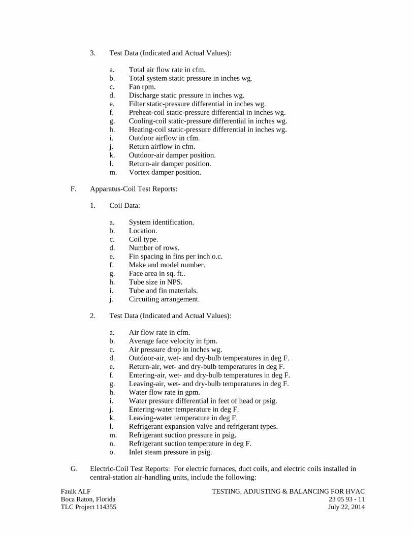
3. Test Data (Indicated and Actual Values):
a. Total air flow rate in cfm. b. Total system static pressure in inches wg. c. Fan rpm. d. Discharge static pressure in inches wg. e. Filter static-pressure differential in inches wg. f. Preheat-coil static-pressure differential in inches wg. g. Cooling-coil static-pressure differential in inches wg. h. Heating-coil static-pressure differential in inches wg. i. Outdoor airflow in cfm. j. Return airflow in cfm. k. Outdoor-air damper position. l. Return-air damper position. m. Vortex damper position.
F. Apparatus-Coil Test Reports:
1. Coil Data:
a. System identification. b. Location. c. Coil type. d. Number of rows. e. Fin spacing in fins per inch o.c. f. Make and model number. g. Face area in sq. ft.. h. Tube size in NPS. i. Tube and fin materials. j. Circuiting arrangement.
2. Test Data (Indicated and Actual Values):
a. Air flow rate in cfm. b. Average face velocity in fpm. c. Air pressure drop in inches wg. d. Outdoor-air, wet- and dry-bulb temperatures in deg F. e. Return-air, wet- and dry-bulb temperatures in deg F. f. Entering-air, wet- and dry-bulb temperatures in deg F. g. Leaving-air, wet- and dry-bulb temperatures in deg F. h. Water flow rate in gpm. i. Water pressure differential in feet of head or psig. j. Entering-water temperature in deg F. k. Leaving-water temperature in deg F. l. Refrigerant expansion valve and refrigerant types. m. Refrigerant suction pressure in psig. n. Refrigerant suction temperature in deg F. o. Inlet steam pressure in psig.
G. Electric-Coil Test Reports: For electric furnaces, duct coils, and electric coils installed in central-station air-handling units, include the following:
Faulk ALF TESTING, ADJUSTING & BALANCING FOR HVAC Boca Raton, Florida 23 05 93 - 11 TLC Project 114355 July 22, 2014
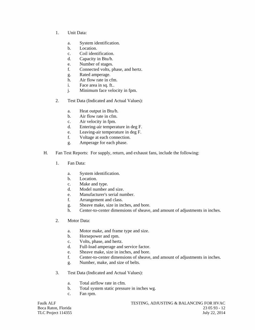
1. Unit Data:
a. System identification. b. Location. c. Coil identification. d. Capacity in Btu/h. e. Number of stages. f. Connected volts, phase, and hertz. g. Rated amperage. h. Air flow rate in cfm. i. Face area in sq. ft.. j. Minimum face velocity in fpm.
2. Test Data (Indicated and Actual Values):
a. Heat output in Btu/h. b. Air flow rate in cfm. c. Air velocity in fpm. d. Entering-air temperature in deg F. e. Leaving-air temperature in deg F. f. Voltage at each connection. g. Amperage for each phase.
H. Fan Test Reports: For supply, return, and exhaust fans, include the following:
1. Fan Data:
a. System identification. b. Location. c. Make and type. d. Model number and size. e. Manufacturer's serial number. f. Arrangement and class. g. Sheave make, size in inches, and bore. h. Center-to-center dimensions of sheave, and amount of adjustments in inches.
2. Motor Data:
a. Motor make, and frame type and size. b. Horsepower and rpm. c. Volts, phase, and hertz. d. Full-load amperage and service factor. e. Sheave make, size in inches, and bore. f. Center-to-center dimensions of sheave, and amount of adjustments in inches. g. Number, make, and size of belts.
3. Test Data (Indicated and Actual Values):
a. Total airflow rate in cfm. b. Total system static pressure in inches wg. c. Fan rpm.
Faulk ALF TESTING, ADJUSTING & BALANCING FOR HVAC Boca Raton, Florida 23 05 93 - 12 TLC Project 114355 July 22, 2014
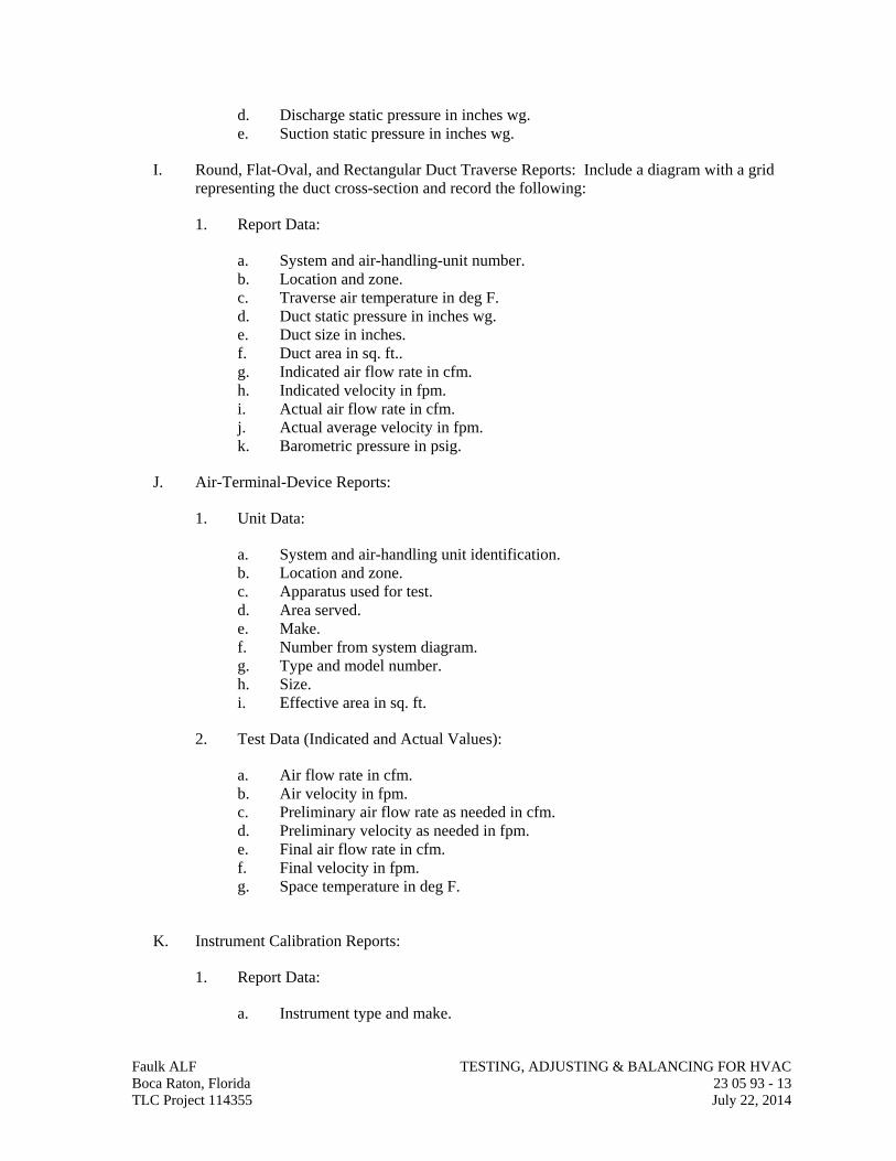
d. Discharge static pressure in inches wg. e. Suction static pressure in inches wg.
I. Round, Flat-Oval, and Rectangular Duct Traverse Reports: Include a diagram with a grid representing the duct cross-section and record the following:
1. Report Data:
a. System and air-handling-unit number. b. Location and zone. c. Traverse air temperature in deg F. d. Duct static pressure in inches wg. e. Duct size in inches. f. Duct area in sq. ft.. g. Indicated air flow rate in cfm. h. Indicated velocity in fpm. i. Actual air flow rate in cfm. j. Actual average velocity in fpm. k. Barometric pressure in psig.
J. Air-Terminal-Device Reports:
1. Unit Data:
a. System and air-handling unit identification. b. Location and zone. c. Apparatus used for test. d. Area served. e. Make. f. Number from system diagram. g. Type and model number. h. Size. i. Effective area in sq. ft.
2. Test Data (Indicated and Actual Values):
a. Air flow rate in cfm. b. Air velocity in fpm. c. Preliminary air flow rate as needed in cfm. d. Preliminary velocity as needed in fpm. e. Final air flow rate in cfm. f. Final velocity in fpm. g. Space temperature in deg F.
K. Instrument Calibration Reports:
1. Report Data:
a. Instrument type and make.
Faulk ALF TESTING, ADJUSTING & BALANCING FOR HVAC Boca Raton, Florida 23 05 93 - 13 TLC Project 114355 July 22, 2014
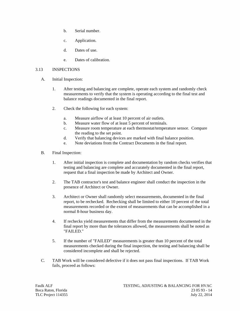
b. Serial number.
c. Application.
d. Dates of use.
e. Dates of calibration.
3.13 INSPECTIONS
A. Initial Inspection:
1. After testing and balancing are complete, operate each system and randomly check measurements to verify that the system is operating according to the final test and balance readings documented in the final report.
2. Check the following for each system:
a. Measure airflow of at least 10 percent of air outlets. b. Measure water flow of at least 5 percent of terminals. c. Measure room temperature at each thermostat/temperature sensor. Compare
the reading to the set point. d. Verify that balancing devices are marked with final balance position. e. Note deviations from the Contract Documents in the final report.
B. Final Inspection:
1. After initial inspection is complete and documentation by random checks verifies that testing and balancing are complete and accurately documented in the final report, request that a final inspection be made by Architect and Owner.
2. The TAB contractor's test and balance engineer shall conduct the inspection in the presence of Architect or Owner.
3. Architect or Owner shall randomly select measurements, documented in the final report, to be rechecked. Rechecking shall be limited to either 10 percent of the total measurements recorded or the extent of measurements that can be accomplished in a normal 8-hour business day.
4. If rechecks yield measurements that differ from the measurements documented in the final report by more than the tolerances allowed, the measurements shall be noted as "FAILED."
5. If the number of "FAILED" measurements is greater than 10 percent of the total measurements checked during the final inspection, the testing and balancing shall be considered incomplete and shall be rejected.
C. TAB Work will be considered defective if it does not pass final inspections. If TAB Work fails, proceed as follows:
Faulk ALF TESTING, ADJUSTING & BALANCING FOR HVAC Boca Raton, Florida 23 05 93 - 14 TLC Project 114355 July 22, 2014
Faulk ALF TESTING, ADJUSTING & BALANCING FOR HVAC Boca Raton, Florida 23 05 93 - 15 TLC Project 114355 July 22, 2014
1. Recheck all measurements and make adjustments. Revise the final report and balancing device settings to include all changes; resubmit the final report and request a second final inspection.
2. If the second final inspection also fails, Owner may contract the services of another TAB contractor to complete TAB Work according to the Contract Documents and deduct the cost of the services from the original TAB contractor's final payment.
D. Prepare test and inspection reports.
3.14 ADDITIONAL TESTS
A. Within 90 days of completing TAB, perform additional TAB to verify that balanced conditions are being maintained throughout and to correct unusual conditions.
B. Seasonal Periods: If initial TAB procedures were not performed during near-peak summer and winter conditions, perform additional TAB during near-peak summer and winter conditions.
END OF SECTION 23 05 93
SECTION 23 07 13
DUCT INSULATION
Faulk ALF DUCT INSULATION Boca Raton, Florida 23 07 13 - 1 TLC Project 114355 July 22, 2014
PART 1 - GENERAL
1.01 RELATED DOCUMENTS
A. Drawings and general provisions of the Contract, including General and Supplementary Conditions and Division 01 Specification Sections, apply to this Section.
1.02 SUMMARY
A. Section includes insulating the following duct services:
1. Indoor, concealed supply and outdoor air. 2. Indoor, exposed supply and outdoor air. 3. Indoor, concealed return air. 4. Indoor, exposed return air. 5. Indoor, concealed, Type I, commercial, kitchen hood exhaust. 6. Indoor, exposed, Type I, commercial, kitchen hood exhaust. 7. Indoor, concealed exhaust between isolation damper and penetration of building
exterior. 8. Outdoor, concealed supply and return. 9. Outdoor, exposed supply and return.
1.03 ACTION SUBMITTALS
A. Product Data: For each type of product indicated. Include thermal conductivity, water-vapor permeance thickness, and jackets (both factory- and field-applied if any).
B. Shop Drawings: Include plans, elevations, sections, details, and attachments to other work.
1. Detail application of protective shields, saddles, and inserts at hangers for each type of insulation and hanger.
2. Detail insulation application at elbows, fittings, dampers, specialties and flanges for each type of insulation.
3. Detail application of field-applied jackets. 4. Detail application at linkages of control devices.
1.04 INFORMATIONAL SUBMITTALS
A. Qualification Data: For qualified Installer.
B. Material Test Reports: From a qualified testing agency acceptable to authorities having jurisdiction indicating, interpreting, and certifying test results for compliance of insulation materials, sealers, attachments, cements, and jackets, with requirements indicated. Include dates of tests and test methods employed.
C. Field quality-control reports.
1.05 QUALITY ASSURANCE
A. Installer Qualifications: Skilled mechanics who have successfully completed an apprenticeship program or another craft training program certified by the Department of Labor, Bureau of Apprenticeship and Training.
B. Surface-Burning Characteristics: For insulation and related materials, as determined by testing identical products according to ASTM E 84, by a testing agency acceptable to authorities having jurisdiction. Factory label insulation and jacket materials and adhesive, mastic, tapes, and cement material containers, with appropriate markings of applicable testing agency.
1. Insulation Installed Indoors: Flame-spread index of 25 or less, and smoke-developed index of 50 or less.
2. Insulation Installed Outdoors: Flame-spread index of 75 or less, and smoke-developed index of 150 or less.
1.06 DELIVERY, STORAGE AND HANDLING
A. Packaging: Insulation material containers shall be marked by manufacturer with appropriate ASTM standard designation, type and grade, and maximum use temperature.
1.07 COORDINATION
A. Coordinate sizes and locations of supports, hangers, and insulation shields specified in Section 230529 "Hangers and Supports for HVAC Piping and Equipment."
B. Coordinate clearance requirements with duct Installer for duct insulation application. Before preparing ductwork Shop Drawings, establish and maintain clearance requirements for installation of insulation and field-applied jackets and finishes and for space required for maintenance.
C. Coordinate installation and testing of heat tracing.
1.08 SCHEDULING
A. Schedule insulation application after pressure testing systems and, where required, after installing and testing heat tracing. Insulation application may begin on segments that have satisfactory test results.
B. Complete installation and concealment of plastic materials as rapidly as possible in each area of construction.
PART 2 - PRODUCTS
2.01 INSULATION MATERIALS
A. Comply with requirements in "Duct Insulation Schedule, General," "Indoor Duct and Plenum Insulation Schedule," and "Aboveground, Outdoor Duct and Plenum Insulation Schedule" articles for where insulating materials shall be applied.
Faulk ALF DUCT INSULATION Boca Raton, Florida 23 07 13 - 2 TLC Project 114355 July 22, 2014
B. Products shall not contain asbestos, lead, mercury, or mercury compounds.
C. Products that come in contact with stainless steel shall have a leachable chloride content of less than 50 ppm when tested according to ASTM C 871.
D. Insulation materials for use on austenitic stainless steel shall be qualified as acceptable according to ASTM C 795.
E. Foam insulation materials shall not use CFC or HCFC blowing agents in the manufacturing process.
F. Flexible Elastomeric Insulation: Closed-cell, sponge- or expanded-rubber materials. Comply with ASTM C 534, Type II for sheet materials.
1. Products: Subject to compliance with requirements, provide one of the following:
a. Aeroflex USA, Inc.; Aerocel. b. Armacell LLC; AP Armaflex. c. K-Flex USA; Insul-Sheet, K-Flex Gray Duct Liner, and K-FLEX LS.
G. Mineral-Fiber Blanket Insulation: Mineral or glass fibers bonded with a thermosetting resin. Comply with ASTM C 553, Type II and ASTM C 1290, Type III with factory-applied FSK jacket. Factory-applied jacket requirements are specified in "Factory-Applied Jackets" Article.
1. Products: Subject to compliance with requirements, provide one of the following:
a. CertainTeed Corp.; SoftTouch Duct Wrap. b. Johns Manville; Microlite. c. Knauf Insulation; Friendly Feel Duct Wrap. d. Manson Insulation Inc.; Alley Wrap. e. Owens Corning; SOFTR All-Service Duct Wrap.
H. Mineral-Fiber Board Insulation: Mineral or glass fibers bonded with a thermosetting resin. Comply with ASTM C 612, Type IA or Type IB. For duct and plenum applications, provide insulation with factory-applied FSK jacket. Factory-applied jacket requirements are specified in "Factory-Applied Jackets" Article.
1. Products: Subject to compliance with requirements, provide one of the following:
a. CertainTeed Corp.; Commercial Board. b. Fibrex Insulations Inc.; FBX. c. Johns Manville; 800 Series Spin-Glas. d. Knauf Insulation; Insulation Board. e. Manson Insulation Inc.; AK Board. f. Owens Corning; Fiberglas 700 Series.
I. Mineral-Fiber, Pipe and Tank Insulation: Mineral or glass fibers bonded with a thermosetting resin. Semirigid board material with factory-applied FSK jacket complying with ASTM C 1393, Type II or Type IIIA Category 2, or with properties similar to ASTM C 612, Type IB. Nominal density is 2.5 lb/cu. ft. or more. Thermal conductivity (k-
Faulk ALF DUCT INSULATION Boca Raton, Florida 23 07 13 - 3 TLC Project 114355 July 22, 2014
value) at 100 deg F is 0.29 Btu x in./h x sq. ft. x deg F or less. Factory-applied jacket requirements are specified in "Factory-Applied Jackets" Article.
1. Products: Subject to compliance with requirements, provide one of the following:
a. CertainTeed Corp.; CrimpWrap. b. Johns Manville; MicroFlex. c. Knauf Insulation; Pipe and Tank Insulation. d. Manson Insulation Inc.; AK Flex. e. Owens Corning; Fiberglas Pipe and Tank Insulation.
J. Polyolefin: Unicellular, polyethylene thermal plastic insulation. Comply with ASTM C 534 or ASTM C 1427, Type I, Grade 1 for tubular materials and Type II, Grade 1 for sheet materials.
1. Products: Subject to compliance with requirements, provide one of the following:
a. Armacell LLC; Tubolit. b. Nomaco Insulation; IMCOLOCK, IMCOSHEET, NOMALOCK, and
NOMAPLY.
2.02 FIRE-RATED INSULATION SYSTEMS
A. Fire-Rated Board: Structural-grade, press-molded, xonolite calcium silicate, fireproofing board suitable for operating temperatures up to 1700 deg F. Comply with ASTM C 656, Type II, Grade 6. Tested and certified to provide a 1 or 2 hour fire rating by an NRTL acceptable to authorities having jurisdiction.
1. Products: Subject to compliance with requirements, provide one of the following:
a. Johns Manville; Super Firetemp M.
B. Fire-Rated Blanket: High-temperature, flexible, blanket insulation with FSK jacket that is tested and certified to provide a 1 or 2 hour fire rating by an NRTL acceptable to authorities having jurisdiction.
1. Products: Subject to compliance with requirements, provide one of the following:
a. CertainTeed Corp.; FlameChek. b. Johns Manville; Firetemp Wrap. c. Nelson Fire Stop Products; Nelson FSB Flameshield Blanket. d. Thermal Ceramics; FireMaster Duct Wrap. e. 3M; Fire Barrier Wrap Products. f. Unifrax Corporation; FyreWrap.
2.03 ADHESIVES
A. Materials shall be compatible with insulation materials, jackets, and substrates and for bonding insulation to itself and to surfaces to be insulated unless otherwise indicated.
Faulk ALF DUCT INSULATION Boca Raton, Florida 23 07 13 - 4 TLC Project 114355 July 22, 2014
B. Flexible Elastomeric and Polyolefin Adhesive: Comply with MIL-A-24179A, Type II, Class I.
1. Products: Subject to compliance with requirements, provide one of the following:
a. Aeroflex USA, Inc.; Aeroseal. b. Armacell LLC; Armaflex 520 Adhesive. c. Foster Brand, Specialty Construction Brands, Inc., a business of H. B. Fuller
Company; 85-75.K-Flex USA; R-373 Contact Adhesive.
2. For indoor applications, adhesive shall have a VOC content of 50 g/L or less when calculated according to 40 CFR 59, Subpart D (EPA Method 24).
3. Adhesive shall comply with the testing and product requirements of the California Department of Health Services' "Standard Practice for the Testing of Volatile Organic Emissions from Various Sources Using Small-Scale Environmental Chambers."
C. Mineral-Fiber Adhesive: Comply with MIL-A-3316C, Class 2, Grade A.
1. Products: Subject to compliance with requirements, provide one of the following:
a. Childers Brand, Specialty Construction Brands, Inc., a business of H. B. Fuller Company; CP-127.Eagle Bridges - Marathon Industries; 225.
b. Foster Brand, Specialty Construction Brands, Inc., a business of H. B. Fuller Company; 85-60/85-70.Mon-Eco Industries, Inc.; 22-25.
2. For indoor applications, adhesive shall have a VOC content of 80 g/L or less when calculated according to 40 CFR 59, Subpart D (EPA Method 24).
3. Adhesive shall comply with the testing and product requirements of the California Department of Health Services' "Standard Practice for the Testing of Volatile Organic Emissions from Various Sources Using Small-Scale Environmental Chambers."
D. ASJ Adhesive, and FSK Jacket Adhesive: Comply with MIL-A-3316C, Class 2, Grade A for bonding insulation jacket lap seams and joints.
1. Products: Subject to compliance with requirements, provide one of the following:
a. Childers Brand, Specialty Construction Brands, Inc., a business of H. B. Fuller Company; CP-82.
b. Eagle Bridges - Marathon Industries; 225. c. Foster Brand, Specialty Construction Brands, Inc., a business of H. B. Fuller
Company; 85-50.Mon-Eco Industries, Inc.; 22-25.
2. For indoor applications, adhesive shall have a VOC content of 50 g/L or less when calculated according to 40 CFR 59, Subpart D (EPA Method 24).
Faulk ALF DUCT INSULATION Boca Raton, Florida 23 07 13 - 5 TLC Project 114355 July 22, 2014
3. Adhesive shall comply with the testing and product requirements of the California Department of Health Services' "Standard Practice for the Testing of Volatile Organic Emissions from Various Sources Using Small-Scale Environmental Chambers."
E. PVC Jacket Adhesive: Compatible with PVC jacket.
1. Products: Subject to compliance with requirements, provide one of the following:
a. Dow Corning Corporation; 739, Dow Silicone. b. Johns Manville; Zeston Perma-Weld, CEEL-TITE Solvent Welding Adhesive. c. P.I.C. Plastics, Inc.; Welding Adhesive. d. Speedline Corporation; Polyco VP Adhesive.
2. For indoor applications, adhesive shall have a VOC content of 50 g/L or less when calculated according to 40 CFR 59, Subpart D (EPA Method 24).
3. Adhesive shall comply with the testing and product requirements of the California Department of Health Services' "Standard Practice for the Testing of Volatile Organic Emissions from Various Sources Using Small-Scale Environmental Chambers."
2.04 MASTICS
A. Materials shall be compatible with insulation materials, jackets, and substrates; comply with MIL-PRF-19565C, Type II.
1. For indoor applications, use mastics that have a VOC content of 50 g/L or less when calculated according to 40 CFR 59, Subpart D (EPA Method 24).
B. Vapor-Barrier Mastic: Water based; suitable for indoor use on below ambient services.
1. Products: Subject to compliance with requirements, provide one of the following:
a. Foster Brand, Specialty Construction Brands, Inc., a business of H. B. Fuller Company; 30-80/30-90.
b. Vimasco Corporation; 749.
2. Water-Vapor Permeance: ASTM E 96/E 96M, Procedure B, 0.013 perm at 43-mil dry film thickness.
3. Service Temperature Range: Minus 20 to plus 180 deg F. 4. Solids Content: ASTM D 1644, 58 percent by volume and 70 percent by weight. 5. Color: White.
C. Vapor-Barrier Mastic: Solvent based; suitable for indoor use on below ambient services.
1. Products: Subject to compliance with requirements, provide one of the following:
a. Childers Brand, Specialty Construction Brands, Inc., a business of H. B. Fuller Company; CP-30.
b. Eagle Bridges - Marathon Industries; 501.
Faulk ALF DUCT INSULATION Boca Raton, Florida 23 07 13 - 6 TLC Project 114355 July 22, 2014
c. Foster Brand, Specialty Construction Brands, Inc., a business of H. B. Fuller Company; 30-35.
d. Mon-Eco Industries, Inc.; 55-10.
2. Water-Vapor Permeance: ASTM F 1249, 0.05 perm at 35-mil dry film thickness. 3. Service Temperature Range: 0 to 180 deg F. 4. Solids Content: ASTM D 1644, 44 percent by volume and 62 percent by weight. 5. Color: White.
D. Vapor-Barrier Mastic: Solvent based; suitable for outdoor use on below ambient services.
1. Products: Subject to compliance with requirements, provide one of the following:
a. Childers Brand, Specialty Construction Brands, Inc., a business of H. B. Fuller Company; Encacel.
b. Eagle Bridges - Marathon Industries; 570. c. Foster Brand, Specialty Construction Brands, Inc., a business of H. B. Fuller
Company; 60-95/60-96.
2. Water-Vapor Permeance: ASTM F 1249, 0.05 perm at 30-mil dry film thickness. 3. Service Temperature Range: Minus 50 to plus 220 deg F. 4. Solids Content: ASTM D 1644, 33 percent by volume and 46 percent by weight. 5. Color: White.
E. Breather Mastic: Water based; suitable for indoor and outdoor use on above ambient services.
1. Products: Subject to compliance with requirements, provide one of the following:
a. Childers Brand, Specialty Construction Brands, Inc., a business of H. B. Fuller Company; CP-10.
b. Eagle Bridges - Marathon Industries; 550. c. Foster Brand, Specialty Construction Brands, Inc., a business of H. B. Fuller
Company; 46-50. d. Mon-Eco Industries, Inc.; 55-50. e. Vimasco Corporation; WC-1/WC-5.
2. Water-Vapor Permeance: ASTM F 1249, 1.8 perms at 0.0625-inch dry film thickness.
3. Service Temperature Range: Minus 20 to plus 180 deg F. 4. Solids Content: 60 percent by volume and 66 percent by weight. 5. Color: White.
2.05 LAGGING ADHESIVES
A. Description: Comply with MIL-A-3316C, Class I, Grade A and shall be compatible with insulation materials, jackets, and substrates.
1. For indoor applications, use lagging adhesives that have a VOC content of 50 g/L or less when calculated according to 40 CFR 59, Subpart D (EPA Method 24).
Faulk ALF DUCT INSULATION Boca Raton, Florida 23 07 13 - 7 TLC Project 114355 July 22, 2014
2. Products: Subject to compliance with requirements, provide one of the following:
a. Childers Brand, Specialty Construction Brands, Inc., a business of H. B. Fuller Company; CP-50 AHV2.Foster Brand, Specialty Construction Brands, Inc., a business of H. B. Fuller Company; 30-36.
b. Vimasco Corporation; 713 and 714.
3. Fire-resistant, water-based lagging adhesive and coating for use indoors to adhere fire-resistant lagging cloths over duct insulation.
4. Service Temperature Range: 0 to plus 180 deg F. 5. Color: White.
2.06 SEALANTS
A. FSK and Metal Jacket Flashing Sealants:
1. Products: Subject to compliance with requirements, provide one of the following:
a. Childers Brand, Specialty Construction Brands, Inc., a business of H. B. Fuller Company; CP-76.Eagle Bridges - Marathon Industries; 405.
b. Foster Brand, Specialty Construction Brands, Inc., a business of H. B. Fuller Company; 95-44.
c. Mon-Eco Industries, Inc.; 44-05.
2. Materials shall be compatible with insulation materials, jackets, and substrates. 3. Fire- and water-resistant, flexible, elastomeric sealant. 4. Service Temperature Range: Minus 40 to plus 250 deg F. 5. Color: Aluminum. 6. For indoor applications, sealants shall have a VOC content of 420 g/L or less when
calculated according to 40 CFR 59, Subpart D (EPA Method 24). 7. Sealants shall comply with the testing and product requirements of the California
Department of Health Services' "Standard Practice for the Testing of Volatile Organic Emissions from Various Sources Using Small-Scale Environmental Chambers."
B. ASJ Flashing Sealants, and Vinyl and PVC Jacket Flashing Sealants:
1. Products: Subject to compliance with requirements, provide one of the following:
a. Childers Brand, Specialty Construction Brands, Inc., a business of H. B. Fuller Company; CP-76.
2. Materials shall be compatible with insulation materials, jackets, and substrates. 3. Fire- and water-resistant, flexible, elastomeric sealant. 4. Service Temperature Range: Minus 40 to plus 250 deg F. 5. Color: White. 6. For indoor applications, sealants shall have a VOC content of 420 g/L or less when
calculated according to 40 CFR 59, Subpart D (EPA Method 24).
Faulk ALF DUCT INSULATION Boca Raton, Florida 23 07 13 - 8 TLC Project 114355 July 22, 2014
7. Sealants shall comply with the testing and product requirements of the California Department of Health Services' "Standard Practice for the Testing of Volatile Organic Emissions from Various Sources Using Small-Scale Environmental Chambers."
2.07 FACTORY-APPLIED JACKETS
A. Insulation system schedules indicate factory-applied jackets on various applications. When factory-applied jackets are indicated, comply with the following:
1. ASJ: White, kraft-paper, fiberglass-reinforced scrim with aluminum-foil backing; complying with ASTM C 1136, Type I.
2. ASJ-SSL: ASJ with self-sealing, pressure-sensitive, acrylic-based adhesive covered by a removable protective strip; complying with ASTM C 1136, Type I.
3. FSK Jacket: Aluminum-foil, fiberglass-reinforced scrim with kraft-paper backing; complying with ASTM C 1136, Type II.
4. FSP Jacket: Aluminum-foil, fiberglass-reinforced scrim with polyethylene backing; complying with ASTM C 1136, Type II.
5. Vinyl Jacket: White vinyl with a permeance of 1.3 perms when tested according to ASTM E 96/E 96M, Procedure A, and complying with NFPA 90A and NFPA 90B.
2.08 FIELD-APPLIED FABRIC-REINFORCING MESH
A. Woven Glass-Fiber Fabric: Approximately 6 oz./sq. yd. with a thread count of 5 strands by 5 strands/sq. in. for covering ducts.
1. Products: Subject to compliance with requirements, provide one of the following:
a. Childers Brand, Specialty Construction Brands, Inc., a business of H. B. Fuller Company; Chil-Glas No. 5.
B. Woven Polyester Fabric: Approximately 1 oz./sq. yd. with a thread count of 10 strands by 10 strands/sq. in., in a Leno weave, for ducts.
1. Products: Subject to compliance with requirements, provide one of the following:
a. Foster Brand, Specialty Construction Brands, Inc., a business of H. B. Fuller Company; Mast-A-Fab.
b. Vimasco Corporation; Elastafab 894.
2.09 FIELD-APPLIED CLOTHS
A. Woven Glass-Fiber Fabric: Comply with MIL-C-20079H, Type I, plain weave, and presized a minimum of 8 oz./sq. yd.
1. Products: Subject to compliance with requirements, provide one of the following: a. Alpha Associates, Inc.; Alpha-Maritex 84215 and 84217/9485RW, Luben 59.
Faulk ALF DUCT INSULATION Boca Raton, Florida 23 07 13 - 9 TLC Project 114355 July 22, 2014
2.10 FIELD-APPLIED JACKETS
A. Field-applied jackets shall comply with ASTM C 921, Type I, unless otherwise indicated.
B. FSK Jacket: Aluminum-foil-face, fiberglass-reinforced scrim with kraft-paper backing.
C. PVC Jacket: High-impact-resistant, UV-resistant PVC complying with ASTM D 1784, Class 16354-C; thickness as scheduled; roll stock ready for shop or field cutting and forming. Thickness is indicated in field-applied jacket schedules.
1. Products: Subject to compliance with requirements, provide one of the following:
a. Johns Manville; Zeston. b. P.I.C. Plastics, Inc.; FG Series. c. Proto Corporation; LoSmoke. d. Speedline Corporation; SmokeSafe.
2. Adhesive: As recommended by jacket material manufacturer. 3. Color: White
D. Metal Jacket:
1. Products: Subject to compliance with requirements, provide one of the following:
a. Childers Brand, Specialty Construction Brands, Inc., a business of H. B. Fuller Company; Metal Jacketing Systems.
b. ITW Insulation Systems; Aluminum and Stainless Steel Jacketing. c. RPR Products, Inc.; Insul-Mate.
2. Aluminum Jacket: Comply with ASTM B 209, Alloy 3003, 3005, 3105, or 5005, Temper H-14.
a. Sheet and roll stock ready for shop or field sizing. b. Finish and thickness are indicated in field-applied jacket schedules. c. Moisture Barrier for Indoor Applications: 1-mil- thick, heat-bonded
polyethylene and kraft paper. d. Moisture Barrier for Outdoor Applications: 3-mil- thick, heat-bonded
polyethylene and kraft paper.
E. Self-Adhesive Outdoor Jacket: 60-mil- thick, laminated vapor barrier and waterproofing membrane for installation over insulation located aboveground outdoors; consisting of a rubberized bituminous resin on a crosslaminated polyethylene film covered with white aluminum-foil facing.
1. Products: Subject to compliance with requirements, provide one of the following:
a. Polyguard Products, Inc.; Alumaguard 60.
Faulk ALF DUCT INSULATION Boca Raton, Florida 23 07 13 - 10 TLC Project 114355 July 22, 2014
2.11 TAPES
A. ASJ Tape: White vapor-retarder tape matching factory-applied jacket with acrylic adhesive, complying with ASTM C 1136.
1. Products: Subject to compliance with requirements, provide one of the following:
a. ABI, Ideal Tape Division; 428 AWF ASJ. b. Avery Dennison Corporation, Specialty Tapes Division; Fasson 0836. c. Compac Corporation; 104 and 105. d. Venture Tape; 1540 CW Plus, 1542 CW Plus, and 1542 CW Plus/SQ.
2. Width: 3 inches. 3. Thickness: 11.5 mils. 4. Adhesion: 90 ounces force/inch in width. 5. Elongation: 2 percent. 6. Tensile Strength: 40 lbf/inch in width. 7. ASJ Tape Disks and Squares: Precut disks or squares of ASJ tape.
B. FSK Tape: Foil-face, vapor-retarder tape matching factory-applied jacket with acrylic adhesive; complying with ASTM C 1136.
1. Products: Subject to compliance with requirements, provide one of the following:
a. ABI, Ideal Tape Division; 491 AWF FSK. b. Avery Dennison Corporation, Specialty Tapes Division; Fasson 0827. c. Compac Corporation; 110 and 111. d. Venture Tape; 1525 CW NT, 1528 CW, and 1528 CW/SQ.
2. Width: 3 inches. 3. Thickness: 6.5 mils. 4. Adhesion: 90 ounces force/inch in width. 5. Elongation: 2 percent. 6. Tensile Strength: 40 lbf/inch in width. 7. FSK Tape Disks and Squares: Precut disks or squares of FSK tape.
C. PVC Tape: White vapor-retarder tape matching field-applied PVC jacket with acrylic adhesive; suitable for indoor and outdoor applications.
1. Products: Subject to compliance with requirements, provide one of the following:
a. ABI, Ideal Tape Division; 370 White PVC tape. b. Compac Corporation; 130. c. Venture Tape; 1506 CW NS.
2. Width: 2 inches. 3. Thickness: 6 mils. 4. Adhesion: 64 ounces force/inch in width. 5. Elongation: 500 percent. 6. Tensile Strength: 18 lbf/inch in width.
Faulk ALF DUCT INSULATION Boca Raton, Florida 23 07 13 - 11 TLC Project 114355 July 22, 2014
D. Aluminum-Foil Tape: Vapor-retarder tape with acrylic adhesive.
1. Products: Subject to compliance with requirements, provide one of the following:
a. ABI, Ideal Tape Division; 488 AWF. b. Avery Dennison Corporation, Specialty Tapes Division; Fasson 0800. c. Compac Corporation; 120. d. Venture Tape; 3520 CW.
2. Width: 2 inches. 3. Thickness: 3.7 mils. 4. Adhesion: 100 ounces force/inch in width. 5. Elongation: 5 percent. 6. Tensile Strength: 34 lbf/inch in width.
2.12 SECUREMENTS
A. Bands:
1. Products: Subject to compliance with requirements, provide one of the following:
a. ITW Insulation Systems; Gerrard Strapping and Seals. b. RPR Products, Inc.; Insul-Mate Strapping, Seals, and Springs.
2. Stainless Steel: ASTM A 167 or ASTM A 240/A 240M, Type 304; 0.015 inch thick, 1/2 inch wide with closed seal.
3. Aluminum: ASTM B 209, Alloy 3003, 3005, 3105, or 5005; Temper H-14, 0.020 inch thick, 1/2 inch wide.
4. Springs: Twin spring set constructed of stainless steel with ends flat and slotted to accept metal bands. Spring size determined by manufacturer for application.
B. Insulation Pins and Hangers:
1. Capacitor-Discharge-Weld Pins: Copper- or zinc-coated steel pin, fully annealed for capacitor-discharge welding, 0.106-inch diameter shank, length to suit depth of insulation indicated.
a. Products: Subject to compliance with requirements, provide one of the following:
1) AGM Industries, Inc.; CWP-1. 2) GEMCO; CD. 3) Midwest Fasteners, Inc.; CD. 4) Nelson Stud Welding; TPA, TPC, and TPS.
2. Cupped-Head, Capacitor-Discharge-Weld Pins: Copper- or zinc-coated steel pin, fully annealed for capacitor-discharge welding, 0.106-inch diameter shank, length to suit depth of insulation indicated with integral 1-1/2-inch galvanized carbon-steel washer.
Faulk ALF DUCT INSULATION Boca Raton, Florida 23 07 13 - 12 TLC Project 114355 July 22, 2014
a. Products: Subject to compliance with requirements, provide one of the following:
1) AGM Industries, Inc.; CHP-1. 2) GEMCO; Cupped Head Weld Pin. 3) Midwest Fasteners, Inc.; Cupped Head. 4) Nelson Stud Welding; CHP.
3. Metal, Adhesively Attached, Perforated-Base Insulation Hangers: Baseplate welded to projecting spindle that is capable of holding insulation, of thickness indicated, securely in position indicated when self-locking washer is in place. Comply with the following requirements:
a. Products: Subject to compliance with requirements, provide one of the following:
1) AGM Industries, Inc.; Tactoo Perforated Base Insul-Hangers. 2) GEMCO; Perforated Base. 3) Midwest Fasteners, Inc.; Spindle.
b. Baseplate: Perforated, galvanized carbon-steel sheet, 0.030 inch thick by 2 inches square.
c. Spindle: Aluminum, fully annealed, 0.106-inch- diameter shank, length to suit depth of insulation indicated.
d. Adhesive: Recommended by hanger manufacturer. Product with demonstrated capability to bond insulation hanger securely to substrates indicated without damaging insulation, hangers, and substrates.
4. Nonmetal, Adhesively Attached, Perforated-Base Insulation Hangers: Baseplate fastened to projecting spindle that is capable of holding insulation, of thickness indicated, securely in position indicated when self-locking washer is in place. Comply with the following requirements:
a. Products: Subject to compliance with requirements, provide one of the following:
1) GEMCO; Nylon Hangers. 2) Midwest Fasteners, Inc.; Nylon Insulation Hangers.
b. Baseplate: Perforated, nylon sheet, 0.030 inch thick by 1-1/2 inches in diameter.
c. Spindle: Nylon, 0.106-inch- diameter shank, length to suit depth of insulation indicated, up to 2-1/2 inches.
d. Adhesive: Recommended by hanger manufacturer. Product with demonstrated capability to bond insulation hanger securely to substrates indicated without damaging insulation, hangers, and substrates.
5. Self-Sticking-Base Insulation Hangers: Baseplate welded to projecting spindle that is capable of holding insulation, of thickness indicated, securely in position indicated when self-locking washer is in place. Comply with the following requirements:
Faulk ALF DUCT INSULATION Boca Raton, Florida 23 07 13 - 13 TLC Project 114355 July 22, 2014
a. Products: Subject to compliance with requirements, provide one of the following:
1) AGM Industries, Inc.; Tactoo Self-Adhering Insul-Hangers. 2) GEMCO; Peel & Press. 3) Midwest Fasteners, Inc.; Self Stick.
b. Baseplate: Galvanized carbon-steel sheet, 0.030 inch thick by 2 inches square. c. Spindle: Aluminum, fully annealed, 0.106-inch- diameter shank, length to suit
depth of insulation indicated. d. Adhesive-backed base with a peel-off protective cover.
6. Insulation-Retaining Washers: Self-locking washers formed from 0.016-inch- thick, stainless-steel sheet, with beveled edge sized as required to hold insulation securely in place but not less than 1-1/2 inches in diameter.
a. Products: Subject to compliance with requirements, provide one of the following:
1) AGM Industries, Inc.; RC-150. 2) GEMCO; R-150. 3) Midwest Fasteners, Inc.; WA-150. 4) Nelson Stud Welding; Speed Clips.
b. Protect ends with capped self-locking washers incorporating a spring steel insert to ensure permanent retention of cap in exposed locations.
7. Nonmetal Insulation-Retaining Washers: Self-locking washers formed from 0.016-inch- thick nylon sheet, with beveled edge sized as required to hold insulation securely in place but not less than 1-1/2 inches in diameter.
a. Manufacturers: Subject to compliance with requirements, provide products by one of the following:
1) GEMCO. 2) Midwest Fasteners, Inc.
C. Staples: Outward-clinching insulation staples, nominal 3/4-inch- wide, stainless steel or Monel.
D. Wire: 0.062-inch soft-annealed, stainless steel.
1. Manufacturers: Subject to compliance with requirements, provide products by one of the following:
a. C & F Wire.
2.13 CORNER ANGLES
A. PVC Corner Angles: 30 mils thick, minimum 1 by 1 inch, PVC according to ASTM D 1784, Class 16354-C. White or color-coded to match adjacent surface.
Faulk ALF DUCT INSULATION Boca Raton, Florida 23 07 13 - 14 TLC Project 114355 July 22, 2014
B. Aluminum Corner Angles: 0.040 inch thick, minimum 1 by 1 inch, aluminum according to ASTM B 209, Alloy 3003, 3005, 3105, or 5005; Temper H-14.
PART 3 - EXECUTION
3.01 EXAMINATION
A. Examine substrates and conditions for compliance with requirements for installation tolerances and other conditions affecting performance of insulation application.
1. Verify that systems to be insulated have been tested and are free of defects. 2. Verify that surfaces to be insulated are clean and dry.
B. Proceed with installation only after unsatisfactory conditions have been corrected.
3.02 PREPARATION
A. Surface Preparation: Clean and dry surfaces to receive insulation. Remove materials that will adversely affect insulation application.
3.03 GENERAL INSTALLATION REQUIREMENTS
A. Install insulation materials, accessories, and finishes with smooth, straight, and even surfaces; free of voids throughout the length of ducts and fittings.
B. Install insulation materials, vapor barriers or retarders, jackets, and thicknesses required for each item of duct system as specified in insulation system schedules.
C. Install accessories compatible with insulation materials and suitable for the service. Install accessories that do not corrode, soften, or otherwise attack insulation or jacket in either wet or dry state.
D. Install insulation with longitudinal seams at top and bottom of horizontal runs.
E. Install multiple layers of insulation with longitudinal and end seams staggered.
F. Keep insulation materials dry during application and finishing.
G. Install insulation with tight longitudinal seams and end joints. Bond seams and joints with adhesive recommended by insulation material manufacturer.
H. Install insulation with least number of joints practical.
I. Where vapor barrier is indicated, seal joints, seams, and penetrations in insulation at hangers, supports, anchors, and other projections with vapor-barrier mastic.
1. Install insulation continuously through hangers and around anchor attachments.
2. For insulation application where vapor barriers are indicated, extend insulation on anchor legs from point of attachment to supported item to point of attachment to structure. Taper and seal ends at attachment to structure with vapor-barrier mastic.
Faulk ALF DUCT INSULATION Boca Raton, Florida 23 07 13 - 15 TLC Project 114355 July 22, 2014
3. Install insert materials and install insulation to tightly join the insert. Seal insulation to insulation inserts with adhesive or sealing compound recommended by insulation material manufacturer.
J. Apply adhesives, mastics, and sealants at manufacturer's recommended coverage rate and wet and dry film thicknesses.
K. Install insulation with factory-applied jackets as follows:
1. Draw jacket tight and smooth.
2. Cover circumferential joints with 3-inch- wide strips, of same material as insulation jacket. Secure strips with adhesive and outward clinching staples along both edges of strip, spaced 4 inches o.c.
3. Overlap jacket longitudinal seams at least 1-1/2 inches. Clean and dry surface to receive self-sealing lap. Staple laps with outward clinching staples along edge at 4 inches o.c.
a. For below ambient services, apply vapor-barrier mastic over staples.
4. Cover joints and seams with tape, according to insulation material manufacturer's written instructions, to maintain vapor seal.
5. Where vapor barriers are indicated, apply vapor-barrier mastic on seams and joints and at ends adjacent to duct flanges and fittings.
L. Cut insulation in a manner to avoid compressing insulation more than 75 percent of its nominal thickness.
M. Finish installation with systems at operating conditions. Repair joint separations and cracking due to thermal movement.
N. Repair damaged insulation facings by applying same facing material over damaged areas. Extend patches at least 4 inches beyond damaged areas. Adhere, staple, and seal patches similar to butt joints.
3.04 PENETRATIONS
A. Insulation Installation at Roof Penetrations: Install insulation continuously through roof penetrations.
1. Seal penetrations with flashing sealant.
2. For applications requiring only indoor insulation, terminate insulation above roof surface and seal with joint sealant. For applications requiring indoor and outdoor insulation, install insulation for outdoor applications tightly joined to indoor insulation ends. Seal joint with joint sealant.
Faulk ALF DUCT INSULATION Boca Raton, Florida 23 07 13 - 16 TLC Project 114355 July 22, 2014
3. Extend jacket of outdoor insulation outside roof flashing at least 2 inches below top of roof flashing.
4. Seal jacket to roof flashing with flashing sealant.
B. Insulation Installation at Aboveground Exterior Wall Penetrations: Install insulation continuously through wall penetrations.
1. Seal penetrations with flashing sealant.
2. For applications requiring only indoor insulation, terminate insulation inside wall surface and seal with joint sealant. For applications requiring indoor and outdoor insulation, install insulation for outdoor applications tightly joined to indoor insulation ends. Seal joint with joint sealant.
3. Extend jacket of outdoor insulation outside wall flashing and overlap wall flashing at least 2 inches.
4. Seal jacket to wall flashing with flashing sealant.
C. Insulation Installation at Interior Wall and Partition Penetrations (That Are Not Fire Rated): Install insulation continuously through walls and partitions.
D. Insulation Installation at Fire-Rated Wall and Partition Penetrations: Terminate insulation at fire damper sleeves for fire-rated wall and partition penetrations. Externally insulate damper sleeves to match adjacent insulation and overlap duct insulation at least 2 inches.
1. Comply with requirements in Section 078413 "Penetration Firestopping"irestopping and fire-resistive joint sealers.
E. Insulation Installation at Floor Penetrations:
1. Duct: For penetrations through fire-rated assemblies, terminate insulation at fire damper sleeves and externally insulate damper sleeve beyond floor to match adjacent duct insulation. Overlap damper sleeve and duct insulation at least 2 inches.
2. Seal penetrations through fire-rated assemblies. Comply with requirements in Section 078413 "Penetration Firestopping."
3.05 INSTALLATION OF FLEXIBLE ELASTOMERIC INSULATION
A. Seal longitudinal seams and end joints with manufacturer's recommended adhesive to eliminate openings in insulation that allow passage of air to surface being insulated.
3.06 INSTALLATION OF MINERAL-FIBER INSULATION
A. Blanket Insulation Installation on Ducts and Plenums: Secure with adhesive and insulation pins.
1. Apply adhesives according to manufacturer's recommended coverage rates per unit area, for 100 percent coverage of duct and plenum surfaces.
Faulk ALF DUCT INSULATION Boca Raton, Florida 23 07 13 - 17 TLC Project 114355 July 22, 2014
2. Apply adhesive to entire circumference of ducts and to all surfaces of fittings and transitions.
3. Install either capacitor-discharge-weld pins and speed washers or cupped-head, capacitor-discharge-weld pins on sides and bottom of horizontal ducts and sides of vertical ducts as follows:
a. On duct sides with dimensions 18 inches and smaller, place pins along longitudinal centerline of duct. Space 3 inches maximum from insulation end joints, and 16 inches o.c.
b. On duct sides with dimensions larger than 18 inches, place pins 16 inches o.c. each way and 3 inches maximum from insulation joints. Install additional pins to hold insulation tightly against surface at cross bracing.
c. Pins may be omitted from top surface of horizontal, rectangular ducts and plenums.
d. Do not overcompress insulation during installation.
e. Impale insulation over pins and attach speed washers.
f. Cut excess portion of pins extending beyond speed washers or bend parallel with insulation surface. Cover exposed pins and washers with tape matching insulation facing.
4. For ducts and plenums with surface temperatures below ambient, install a continuous unbroken vapor barrier. Create a facing lap for longitudinal seams and end joints with insulation by removing 2 inches from one edge and one end of insulation segment. Secure laps to adjacent insulation section with 1/2-inch outward-clinching staples, 1 inch o.c. Install vapor barrier consisting of factory- or field-applied jacket, adhesive, vapor-barrier mastic, and sealant at joints, seams, and protrusions.
a. Repair punctures, tears, and penetrations with tape or mastic to maintain vapor-barrier seal.
b. Install vapor stops for ductwork and plenums operating below 50 deg F at 18-foot intervals. Vapor stops shall consist of vapor-barrier mastic applied in a Z-shaped pattern over insulation face, along butt end of insulation, and over the surface. Cover insulation face and surface to be insulated a width equal to two times the insulation thickness, but not less than 3 inches.
5. Overlap unfaced blankets a minimum of 2 inches on longitudinal seams and end joints. At end joints, secure with steel bands spaced a maximum of 18 inches o.c.
6. Install insulation on rectangular duct elbows and transitions with a full insulation section for each surface. Install insulation on round and flat-oval duct elbows with individually mitered gores cut to fit the elbow.
Faulk ALF DUCT INSULATION Boca Raton, Florida 23 07 13 - 18 TLC Project 114355 July 22, 2014
7. Insulate duct stiffeners, hangers, and flanges that protrude beyond insulation surface with 6-inch- wide strips of same material used to insulate duct. Secure on alternating sides of stiffener, hanger, and flange with pins spaced 6 inches o.c.
B. Board Insulation Installation on Ducts and Plenums: Secure with adhesive and insulation pins.
1. Apply adhesives according to manufacturer's recommended coverage rates per unit area, for 100 percent coverage of duct and plenum surfaces.
2. Apply adhesive to entire circumference of ducts and to all surfaces of fittings and transitions.
3. Install either capacitor-discharge-weld pins and speed washers or cupped-head, capacitor-discharge-weld pins on sides and bottom of horizontal ducts and sides of vertical ducts as follows:
a. On duct sides with dimensions 18 inches and smaller, place pins along longitudinal centerline of duct. Space 3 inches maximum from insulation end joints, and 16 inches o.c.
b. On duct sides with dimensions larger than 18 inches, space pins 16 inches o.c. each way, and 3 inches maximum from insulation joints. Install additional pins to hold insulation tightly against surface at cross bracing.
c. Pins may be omitted from top surface of horizontal, rectangular ducts and plenums.
d. Do not overcompress insulation during installation. e. Cut excess portion of pins extending beyond speed washers or bend parallel
with insulation surface. Cover exposed pins and washers with tape matching insulation facing.
4. For ducts and plenums with surface temperatures below ambient, install a continuous unbroken vapor barrier. Create a facing lap for longitudinal seams and end joints with insulation by removing 2 inches from one edge and one end of insulation segment. Secure laps to adjacent insulation section with 1/2-inch outward-clinching staples, 1 inch o.c. Install vapor barrier consisting of factory- or field-applied jacket, adhesive, vapor-barrier mastic, and sealant at joints, seams, and protrusions.
a. Repair punctures, tears, and penetrations with tape or mastic to maintain vapor-barrier seal.
b. Install vapor stops for ductwork and plenums operating below 50 deg F at 18-foot intervals. Vapor stops shall consist of vapor-barrier mastic applied in a Z-shaped pattern over insulation face, along butt end of insulation, and over the surface. Cover insulation face and surface to be insulated a width equal to two times the insulation thickness, but not less than 3 inches.
5. Install insulation on rectangular duct elbows and transitions with a full insulation section for each surface. Groove and score insulation to fit as closely as possible to outside and inside radius of elbows. Install insulation on round and flat-oval duct elbows with individually mitered gores cut to fit the elbow.
Faulk ALF DUCT INSULATION Boca Raton, Florida 23 07 13 - 19 TLC Project 114355 July 22, 2014
6. Insulate duct stiffeners, hangers, and flanges that protrude beyond insulation surface with 6-inch- wide strips of same material used to insulate duct. Secure on alternating sides of stiffener, hanger, and flange with pins spaced 6 inches o.c.
3.07 FIELD-APPLIED JACKET INSTALLATION
A. Where glass-cloth jackets are indicated, install directly over bare insulation or insulation with factory-applied jackets.
1. Draw jacket smooth and tight to surface with 2-inch overlap at seams and joints. 2. Embed glass cloth between two 0.062-inch- thick coats of lagging adhesive. 3. Completely encapsulate insulation with coating, leaving no exposed insulation.
B. Where FSK jackets are indicated, install as follows:
1. Draw jacket material smooth and tight. 2. Install lap or joint strips with same material as jacket. 3. Secure jacket to insulation with manufacturer's recommended adhesive. 4. Install jacket with 1-1/2-inch laps at longitudinal seams and 3-inch- wide joint strips
at end joints. 5. Seal openings, punctures, and breaks in vapor-retarder jackets and exposed insulation
with vapor-barrier mastic.
C. Where PVC jackets are indicated, install with 1-inch overlap at longitudinal seams and end joints; for horizontal applications, install with longitudinal seams along top and bottom of tanks and vessels. Seal with manufacturer's recommended adhesive.
1. Apply two continuous beads of adhesive to seams and joints, one bead under lap and the finish bead along seam and joint edge.
D. Where metal jackets are indicated, install with 2-inch overlap at longitudinal seams and end joints. Overlap longitudinal seams arranged to shed water. Seal end joints with weatherproof sealant recommended by insulation manufacturer. Secure jacket with stainless-steel bands 12 inches o.c. and at end joints.
3.08 FIRE-RATED INSULATION SYSTEM INSTALLATION
A. Where fire-rated insulation system is indicated, secure system to ducts and duct hangers and supports to maintain a continuous fire rating.
B. Insulate duct access panels and doors to achieve same fire rating as duct.
C. Install firestopping at penetrations through fire-rated assemblies. Fire-stop systems are specified in Section 078413 "Penetration Firestopping."
3.09 FINISHES
A. Insulation with ASJ, Glass-Cloth, or Other Paintable Jacket Material: Paint jacket with paint system identified below and as specified in Section 099113 "Exterior Painting" and Section 099123 "Interior Painting."
Faulk ALF DUCT INSULATION Boca Raton, Florida 23 07 13 - 20 TLC Project 114355 July 22, 2014
1. Flat Acrylic Finish: Two finish coats over a primer that is compatible with jacket material and finish coat paint. Add fungicidal agent to render fabric mildew proof.
a. Finish Coat Material: Interior, flat, latex-emulsion size.
B. Flexible Elastomeric Thermal Insulation: After adhesive has fully cured, apply two coats of insulation manufacturer's recommended protective coating.
C. Color: Final color as selected by Architect. Vary first and second coats to allow visual inspection of the completed Work.
D. Do not field paint aluminum or stainless-steel jackets.
3.10 FIELD QUALITY CONTROL
A. Testing Agency: Owner will engage a qualified testing agency to perform tests and inspections.
B. Perform tests and inspections.
C. Tests and Inspections:
1. Inspect ductwork, randomly selected by Architect, by removing field-applied jacket and insulation in layers in reverse order of their installation. Extent of inspection shall be limited to one location(s) for each duct system defined in the "Duct Insulation Schedule, General" Article.
D. All insulation applications will be considered defective Work if sample inspection reveals noncompliance with requirements.
3.11 DUCT INSULATION SCHEDULE, GENERAL
A. Plenums and Ducts Requiring Insulation:
1. Indoor, concealed supply and outdoor air. 2. Indoor, exposed supply and outdoor air. 3. Indoor, concealed return air. 4. Indoor, exposed return air. 5. Indoor, concealed, Type I, commercial, kitchen hood exhaust. 6. Indoor, exposed, Type I, commercial, kitchen hood exhaust. 7. Outdoor, concealed supply and return. 8. Outdoor, exposed supply and return.
B. Items Not Insulated:
1. Fibrous-glass ducts. 2. Metal ducts with duct liner of sufficient thickness to comply with energy code and
ASHRAE/IESNA 90.1. 3. Factory-insulated flexible ducts. 4. Factory-insulated plenums and casings. 5. Flexible connectors.
Faulk ALF DUCT INSULATION Boca Raton, Florida 23 07 13 - 21 TLC Project 114355 July 22, 2014
6. Vibration-control devices. 7. Factory-insulated access panels and doors.
3.12 INDOOR DUCT AND PLENUM INSULATION SCHEDULE
A. Concealed, round and flat-oval, supply-air duct insulation shall be one of the following:
1. Mineral Fiber Blanket: 1-1/2 inches thick and nominal density. 2. Mineral Fiber Board: 1-1/2 inches thick and 2-lb/cu. ft. nominal density.
B. Concealed, round and flat-oval, return-air duct insulation shall be one of the following:
1. Mineral-Fiber Blanket: 1-1/2 inches thick and 1.5-lb/cu. ft. nominal density. 2. Mineral-Fiber Board: 1-1/2 inches thick and 2-lb/cu. ft. nominal density.
C. Concealed, round and flat-oval, outdoor-air duct insulation shall be one of the following:
1. Mineral-Fiber Blanket: 1-1/2 inches thick and 1.5-lb/cu. ft. nominal density. 2. Mineral-Fiber Board: 1-1/2 inches thick and 3-lb/cu. ft. nominal density.
D. Concealed, round and flat-oval, exhaust-air duct insulation shall be one of the following:
1. Mineral-Fiber Blanket: 1-1/2 inches thick and 1.5-lb/cu. ft. nominal density. 2. Mineral-Fiber Board: 1-1/2 inches thick and 2-lb/cu. ft. nominal density.
E. Concealed, rectangular, supply-air duct insulation shall be one of the following:
1. Mineral-Fiber Blanket: 1-1/2 inches thick and 1.5-lb/cu. ft. nominal density. 2. Mineral-Fiber Board: 1-1/2 inches thick and 2-lb/cu. ft. nominal density.
F. Concealed, rectangular, return-air duct insulation shall be one of the following:
1. Mineral-Fiber Blanket: 1-1/2 inches thick and 1.5-lb/cu. ft. nominal density. 2. Mineral-Fiber Board: 1-1/2 inches thick and 2-lb/cu. ft. nominal density.
G. Concealed, rectangular, outdoor-air duct insulation shall be one of the following:
1. Mineral-Fiber Blanket: 1-1/2 inches thick and 1.5-lb/cu. ft. nominal density. 2. Mineral-Fiber Board: 1-1/2 inches thick and 2-lb/cu. ft. nominal density.
H. Concealed, Type I, Commercial, Kitchen Hood Exhaust Duct and Plenum Insulation: Fire-rated blanket or board; thickness as required to achieve 2-hour fire rating.
I. Concealed, supply-air plenum insulation shall be one of the following:
1. Mineral-Fiber Blanket: 1-1/2 inches thick and 1.5-lb/cu. ft. nominal density. 2. Mineral-Fiber Board: 1-1/2 inches thick and 2-lb/cu. ft. nominal density.
J. Concealed, return-air plenum insulation shall be one of the following:
1. Mineral-Fiber Blanket: 1-1/2 inches thick and 1.5-lb/cu. ft. nominal density. 2. Mineral-Fiber Board: 1-1/2 inches thick and 2-lb/cu. ft. nominal density.
Faulk ALF DUCT INSULATION Boca Raton, Florida 23 07 13 - 22 TLC Project 114355 July 22, 2014
K. Concealed, outdoor-air plenum insulation shall be one of the following:
1. Mineral-Fiber Blanket: 1-1/2 inches thick and 1.5-lb/cu. ft. nominal density. 2. Mineral-Fiber Board: 1-1/2 inches thick and 2-lb/cu. ft. nominal density.
L. Exposed, round and flat-oval, return-air duct insulation shall be one of the following:
1. Mineral-Fiber Blanket: 1-1/2 inches thick and 1.5-lb/cu. ft. nominal density. 2. Mineral-Fiber Pipe and Tank: 1-1/2 inches thick.
M. Exposed, round and flat-oval, outdoor-air duct insulation shall be one of the following:
1. Mineral-Fiber Blanket: 1-1/2 inches thick and 1.5-lb/cu. ft. nominal density. 2. Mineral-Fiber Pipe and Tank: 1-1/2 inches thick.
N. Exposed, rectangular, supply-air duct insulation shall be one of the following:
1. Mineral-Fiber Board: 1-1/2 inches thick and 2-lb/cu. ft. nominal density.
O. Exposed, rectangular, return-air duct insulation shall be one of the following:
1. Mineral-Fiber Board: 1-1/2 inches thick and 2-lb/cu. ft. nominal density.
P. Exposed, rectangular, outdoor-air duct insulation shall be one of the following:
1. Mineral-Fiber Board: 1-1/2 inches thick and 2-lb/cu. ft. nominal density.
Q. Exposed, Type I, Commercial, Kitchen Hood Exhaust Duct and Plenum Insulation: Fire-rated blanket or board; thickness as required to achieve 2-hour fire rating.
R. Exposed, supply air plenum insulation shall be one of the following:
1. Mineral-Fiber Board: 1-1/2 inches thick and 2-lb/cu. ft. nominal density.
S. Exposed, return-air plenum insulation shall be one of the following:
1. Mineral-Fiber Board: 1-1/2 inches thick and 2-lb/cu. ft. nominal density.
T. Exposed, outdoor-air plenum insulation shall be one of the following:
1. Mineral-Fiber Board: 1-1/2 inches thick and 2-lb/cu. ft. nominal density.
3.13 ABOVEGROUND, OUTDOOR DUCT AND PLENUM INSULATION SCHEDULE
A. Insulation materials and thicknesses are identified below. If more than one material is listed for a duct system, selection from materials listed is Contractor's option.
B. Concealed, round and flat-oval, supply-air duct insulation shall be the following:
1. Mineral-Fiber Board: 2 inches thick and 2-lb/cu. ft. nominal density.
Faulk ALF DUCT INSULATION Boca Raton, Florida 23 07 13 - 23 TLC Project 114355 July 22, 2014
C. Concealed, round and flat-oval, return-air duct insulation shall be the following:
1. Mineral-Fiber Board: 2 inches thick and 2-lb/cu. ft. nominal density.
D. Concealed, rectangular, supply-air duct insulation shall be the following:
1. Mineral-Fiber Board: 2 inches thick and 2-lb/cu. ft. nominal density.
E. Concealed, rectangular, return-air duct insulation shall be the following:
1. Mineral-Fiber Board: 2 inches thick and 2-lb/cu. ft. nominal density.
F. Concealed, supply-air plenum insulation shall be the following:
1. Mineral-Fiber Board: 2 inches thick and 2-lb/cu. ft. nominal density.
G. Concealed, return-air plenum insulation shall be the following:
1. Mineral-Fiber Board: 2 inches thick and 2-lb/cu. ft. nominal density.
H. Exposed, round and flat-oval, supply-air duct insulation shall be the following:
1. Mineral-Fiber Board: 2 inches thick and 2-lb/cu. ft. nominal density. 2. Mineral-Fiber Pipe and Tank: 2 inches thick.
I. Exposed, round and flat-oval, return-air duct insulation shall be the following:
1. Mineral-Fiber Board: 2 inches thick and 2-lb/cu. ft. nominal density.
J. Exposed, rectangular, supply-air duct insulation shall be the following:
1. Mineral-Fiber Board: 2 inches thick and 2-lb/cu. ft. nominal density.
K. Exposed, rectangular, return-air duct insulation shall be the following:
1. Mineral-Fiber Board: 2 inches thick and 2-lb/cu. ft. nominal density.
L. Exposed, supply-air plenum insulation shall be the following:
1. Mineral-Fiber Board: 2 inches thick and 2-lb/cu. ft. nominal density.
M. Exposed, return-air plenum insulation shall be the following:
1. Mineral-Fiber Board: 2 inches thick and 2-lb/cu. ft. nominal density.
3.14 INDOOR, FIELD-APPLIED JACKET SCHEDULE
A. Install jacket over insulation material. For insulation with factory-applied jacket, install the field-applied jacket over the factory-applied jacket.
B. If more than one material is listed, selection from materials listed is Contractor's option.
Faulk ALF DUCT INSULATION Boca Raton, Florida 23 07 13 - 24 TLC Project 114355 July 22, 2014
Faulk ALF DUCT INSULATION Boca Raton, Florida 23 07 13 - 25 TLC Project 114355 July 22, 2014
C. Ducts and Plenums, Concealed:
1. None.
D. Ducts and Plenums, Exposed:
1. None.
3.15 OUTDOOR, FIELD-APPLIED JACKET SCHEDULE
A. Install jacket over insulation material. For insulation with factory-applied jacket, install the field-applied jacket over the factory-applied jacket.
B. If more than one material is listed, selection from materials listed is Contractor's option.
C. Ducts and Plenums, Concealed:
1. Aluminum, Corrugated: 0.020 inch thick.
D. Ducts and Plenums, Exposed, up to 48 Inches in Diameter or with Flat Surfaces up to 72 Inches:
1. Aluminum, Corrugated: 0.020 inch thick.
E. Ducts and Plenums, Exposed, Larger Than 48 Inches in Diameter or with Flat Surfaces Larger Than 72 Inches:
1. Aluminum, Smooth with 1-1/4-Inch- Deep Corrugations thick.
END OF SECTION 23 07 13
SECTION 23 07 19
HVAC PIPING INSULATION
Faulk ALF HVAC PIPING INSULATION Boca Raton, Florida 23 07 19 - 1 TLC Project 114355 July 22, 2014
PART 1 - GENERAL
1.01 RELATED DOCUMENTS
A. Drawings and general provisions of the Contract, including General and Supplementary Conditions and Division 01 Specification Sections, apply to this Section.
1.02 SUMMARY
A. Section includes insulating the following HVAC piping systems:
1. Condensate drain piping, indoors. 2. Refrigerant suction and hot-gas piping, indoors and outdoors.
1.03 ACTION SUBMITTALS
A. Product Data: For each type of product indicated. Include thermal conductivity, water-vapor permeance thickness, and jackets (both factory and field applied if any).
1.04 INFORMATIONAL SUBMITTALS
A. Field quality-control reports.
1.05 QUALITY ASSURANCE
A. Installer Qualifications: Skilled mechanics who have successfully completed an apprenticeship program or another craft training program certified by the Department of Labor, Bureau of Apprenticeship and Training.
B. Surface-Burning Characteristics: For insulation and related materials, as determined by testing identical products according to ASTM E 84, by a testing and inspecting agency acceptable to authorities having jurisdiction. Factory label insulation and jacket materials and adhesive, mastic, tapes, and cement material containers, with appropriate markings of applicable testing agency.
1. Insulation Installed Indoors: Flame-spread index of 25 or less, and smoke-developed index of 50 or less.
2. Insulation Installed Outdoors: Flame-spread index of 75 or less, and smoke-developed index of 150 or less.
1.06 DELIVERY, STORAGE, AND HANDLING
A. Packaging: Insulation material containers shall be marked by manufacturer with appropriate ASTM standard designation, type and grade, and maximum use temperature.
1.07 COORDINATION
A. Coordinate sizes and locations of supports, hangers, and insulation shields specified in Division 23 Section "Hangers and Supports for HVAC Piping and Equipment."
B. Coordinate clearance requirements with piping Installer for piping insulation application. Before preparing piping Shop Drawings establish and maintain clearance requirements for installation of insulation and field-applied jackets and finishes and for space required for maintenance.
C. Coordinate installation and testing of heat tracing.
1.08 SCHEDULING
A. Schedule insulation application after pressure testing systems and, where required, after installing and testing heat tracing. Insulation application may begin on segments that have satisfactory test results.
B. Complete installation and concealment of plastic materials as rapidly as possible in each area of construction.
PART 2 - PRODUCTS
2.01 INSULATION MATERIALS
A. Comply with requirements in "Piping Insulation Schedule, General," "Indoor Piping Insulation Schedule," and "Outdoor, Aboveground Piping Insulation Schedule" articles for where insulating materials shall be applied.
B. Products shall not contain asbestos, lead, mercury, or mercury compounds.
C. Products that come in contact with stainless steel shall have a leachable chloride content of less than 50 ppm when tested according to ASTM C 871.
D. Insulation materials for use on austenitic stainless steel shall be qualified as acceptable according to ASTM C 795.
E. Foam insulation materials shall not use CFC or HCFC blowing agents in the manufacturing process.
F. Flexible Elastomeric Insulation: Closed-cell, sponge- or expanded-rubber materials. Comply with ASTM C 534, Type I for tubular materials.
1. Products: Subject to compliance with requirements, provide the following :
a. Aeroflex USA, Inc.; Aerocel.
b. Armacell LLC; AP Armaflex.
c. K-Flex USA; Insul-Lock, Insul-Tube, and K-FLEX LS.
Faulk ALF HVAC PIPING INSULATION Boca Raton, Florida 23 07 19 - 2 TLC Project 114355 July 22, 2014
G. Mineral-Fiber, Pipe and Tank Insulation: Mineral or glass fibers bonded with a thermosetting resin. Semirigid board material with factory-applied ASJ complying with ASTM C 1393, Type II or Type IIIA Category 2, or with properties similar to ASTM C 612, Type IB. Nominal density is 2.5 lb/cu. ft. or more. Thermal conductivity (k-value) at 100 deg F is 0.29 Btu x in./h x sq. ft. x deg F or less. Factory-applied jacket requirements are specified in "Factory-Applied Jackets" Article.
1. Products: Subject to compliance with requirements, provide the following:
a. CertainTeed Corp.; CrimpWrap. b. Johns Manville; MicroFlex. c. Knauf Insulation; Pipe and Tank Insulation. d. Owens Corning; Fiberglas Pipe and Tank Insulation.
2.02 INSULATING CEMENTS
A. Mineral-Fiber Insulating Cement: Comply with ASTM C 195.
1. Products: Subject to compliance with requirements, provide the following :
a. Ramco Insulation, Inc.; Super-Stik.
B. Mineral-Fiber, Hydraulic-Setting Insulating and Finishing Cement: Comply with ASTM C 449.
1. Products: Subject to compliance with requirements, provide the following :
a. Ramco Insulation, Inc.; Ramcote 1200 and Quik-Cote.
2.03 ADHESIVES
A. Materials shall be compatible with insulation materials, jackets, and substrates and for bonding insulation to itself and to surfaces to be insulated unless otherwise indicated.
B. Flexible Elastomeric Adhesive: Comply with MIL-A-24179A, Type II, Class I.
1. Products: Subject to compliance with requirements, provide the following :
a. Aeroflex USA, Inc.; Aeroseal. b. Armacell LLC; Armaflex 520 Adhesive. c. Foster Brand, Specialty Construction Brands, Inc., a business of H. B. Fuller
Company; 85-75. d. K-Flex USA; R-373 Contact Adhesive.
2. For indoor applications, adhesive shall have a VOC content of 50 g/L or less when calculated according to 40 CFR 59, Subpart D (EPA Method 24).
3. Adhesive shall comply with the testing and product requirements of the California Department of Health Services' "Standard Practice for the Testing of Volatile Organic Emissions from Various Sources Using Small-Scale Environmental Chambers."
Faulk ALF HVAC PIPING INSULATION Boca Raton, Florida 23 07 19 - 3 TLC Project 114355 July 22, 2014
C. Mineral-Fiber Adhesive: Comply with MIL-A-3316C, Class 2, Grade A.
1. Products: Subject to compliance with requirements, provide the following :
a. Childers Brand, Specialty Construction Brands, Inc., a business of H. B. Fuller Company; CP-127.
b. Eagle Bridges - Marathon Industries; 225. c. Foster Brand, Specialty Construction Brands, Inc., a business of H. B. Fuller
Company; 85-60/85-70. d. Mon-Eco Industries, Inc.; 22-25.
2. For indoor applications, adhesive shall have a VOC content of 80 g/L or less when calculated according to 40 CFR 59, Subpart D (EPA Method 24).
3. Adhesive shall comply with the testing and product requirements of the California Department of Health Services' "Standard Practice for the Testing of Volatile Organic Emissions from Various Sources Using Small-Scale Environmental Chambers."
D. ASJ Adhesive: Comply with MIL-A-3316C, Class 2, Grade A for bonding insulation jacket lap seams and joints.
1. Products: Subject to compliance with requirements, provide the following :
a. Childers Brand, Specialty Construction Brands, Inc., a business of H. B. Fuller Company; CP-82.
b. Eagle Bridges - Marathon Industries; 225. c. Foster Brand, Specialty Construction Brands, Inc., a business of H. B. Fuller
Company; 85-50. d. Mon-Eco Industries, Inc.; 22-25.
2. For indoor applications, adhesive shall have a VOC content of 50 g/L or less when calculated according to 40 CFR 59, Subpart D (EPA Method 24).
3. Adhesive shall comply with the testing and product requirements of the California Department of Health Services' "Standard Practice for the Testing of Volatile Organic Emissions from Various Sources Using Small-Scale Environmental Chambers."
E. PVC Jacket Adhesive: Compatible with PVC jacket.
1. Products: Subject to compliance with requirements, provide the following :
a. Dow Corning Corporation; 739, Dow Silicone. b. Johns Manville; Zeston Perma-Weld, CEEL-TITE Solvent Welding Adhesive. c. P.I.C. Plastics, Inc.; Welding Adhesive. d. Speedline Corporation; Polyco VP Adhesive.
2. For indoor applications, adhesive shall have a VOC content of 50 g/L or less when calculated according to 40 CFR 59, Subpart D (EPA Method 24).
Faulk ALF HVAC PIPING INSULATION Boca Raton, Florida 23 07 19 - 4 TLC Project 114355 July 22, 2014
3. Adhesive shall comply with the testing and product requirements of the California Department of Health Services' "Standard Practice for the Testing of Volatile Organic Emissions from Various Sources Using Small-Scale Environmental Chambers."
2.04 MASTICS
A. Materials shall be compatible with insulation materials, jackets, and substrates; comply with MIL-PRF-19565C, Type II.
1. For indoor applications, use mastics that have a VOC content of 50 g/L or less when calculated according to 40 CFR 59, Subpart D (EPA Method 24).
B. Vapor-Barrier Mastic: Water based; suitable for indoor use on below-ambient services.
1. Products: Subject to compliance with requirements, provide the following :
a. Foster Brand, Specialty Construction Brands, Inc., a business of H. B. Fuller Company; 30-80/30-90.
b. Vimasco Corporation; 749.
2. Water-Vapor Permeance: ASTM E 96/E 96M, Procedure B, 0.013 perm at 43-mil dry film thickness.
3. Service Temperature Range: Minus 20 to plus 180 deg F. 4. Solids Content: ASTM D 1644, 58 percent by volume and 70 percent by weight. 5. Color: White.
C. Vapor-Barrier Mastic: Solvent based; suitable for outdoor use on below-ambient services.
1. Products: Subject to compliance with requirements, provide the following :
a. Childers Brand, Specialty Construction Brands, Inc., a business of H. B. Fuller Company; Encacel.
b. Eagle Bridges - Marathon Industries; 570. c. Foster Brand, Specialty Construction Brands, Inc., a business of H. B. Fuller
Company; 60-95/60-96.
2. Water-Vapor Permeance: ASTM F 1249, 0.05 perm at 30-mil dry film thickness. 3. Service Temperature Range: Minus 50 to plus 220 deg F. 4. Solids Content: ASTM D 1644, 33 percent by volume and 46 percent by weight. 5. Color: White.
D. Breather Mastic: Water based; suitable for indoor and outdoor use on above-ambient services.
1. Products: Subject to compliance with requirements, provide the following : a. Childers Brand, Specialty Construction Brands, Inc., a business of H. B. Fuller
Company; CP-10. b. Eagle Bridges - Marathon Industries; 550. c. Foster Brand, Specialty Construction Brands, Inc., a business of H. B. Fuller
Company; 46-50.
Faulk ALF HVAC PIPING INSULATION Boca Raton, Florida 23 07 19 - 5 TLC Project 114355 July 22, 2014
2. Water-Vapor Permeance: ASTM F 1249, 1.8 perms at 0.0625-inch dry film thickness.
3. Service Temperature Range: Minus 20 to plus 180 deg F. 4. Solids Content: 60 percent by volume and 66 percent by weight. 5. Color: White.
2.05 SEALANTS
A. Joint Sealants:
1. Joint Sealants for Cellular-Glass Products: Subject to compliance with requirements, provide the following :
a. Childers Brand, Specialty Construction Brands, Inc., a business of H. B. Fuller Company; CP-76.
b. Eagle Bridges - Marathon Industries; 405. c. Foster Brand, Specialty Construction Brands, Inc., a business of H. B. Fuller
Company; 30-45.
2. Materials shall be compatible with insulation materials, jackets, and substrates. 3. Permanently flexible, elastomeric sealant. 4. Service Temperature Range: Minus 100 to plus 300 deg F. 5. Color: White or gray. 6. For indoor applications, sealants shall have a VOC content of 420 g/L or less when
calculated according to 40 CFR 59, Subpart D (EPA Method 24). 7. Sealants shall comply with the testing and product requirements of the California
Department of Health Services' "Standard Practice for the Testing of Volatile Organic Emissions from Various Sources Using Small-Scale Environmental Chambers."
B. Metal Jacket Flashing Sealants:
1. Products: Subject to compliance with requirements, provide the following :
a. Childers Brand, Specialty Construction Brands, Inc., a business of H. B. Fuller Company; CP-76.
b. Eagle Bridges - Marathon Industries; 405. c. Foster Brand, Specialty Construction Brands, Inc., a business of H. B. Fuller
Company; 95-44.
2. Materials shall be compatible with insulation materials, jackets, and substrates. 3. Fire- and water-resistant, flexible, elastomeric sealant. 4. Service Temperature Range: Minus 40 to plus 250 deg F. 5. Color: Aluminum. 6. For indoor applications, sealants shall have a VOC content of 420 g/L or less when
calculated according to 40 CFR 59, Subpart D (EPA Method 24). 7. Sealants shall comply with the testing and product requirements of the California
Department of Health Services' "Standard Practice for the Testing of Volatile Organic Emissions from Various Sources Using Small-Scale Environmental Chambers."
Faulk ALF HVAC PIPING INSULATION Boca Raton, Florida 23 07 19 - 6 TLC Project 114355 July 22, 2014
C. ASJ Flashing Sealants and PVC Jacket Flashing Sealants:
1. Products: Subject to compliance with requirements, provide the following :
a. Childers Brand, Specialty Construction Brands, Inc., a business of H. B. Fuller Company; CP-76.
2. Materials shall be compatible with insulation materials, jackets, and substrates. 3. Fire- and water-resistant, flexible, elastomeric sealant. 4. Service Temperature Range: Minus 40 to plus 250 deg F. 5. Color: White. 6. For indoor applications, sealants shall have a VOC content of 420 g/L or less when
calculated according to 40 CFR 59, Subpart D (EPA Method 24). 7. Sealants shall comply with the testing and product requirements of the California
Department of Health Services' "Standard Practice for the Testing of Volatile Organic Emissions from Various Sources Using Small-Scale Environmental Chambers."
2.06 FACTORY-APPLIED JACKETS
A. Insulation system schedules indicate factory-applied jackets on various applications. When factory-applied jackets are indicated, comply with the following:
1. ASJ-SSL: ASJ with self-sealing, pressure-sensitive, acrylic-based adhesive covered by a removable protective strip; complying with ASTM C 1136, Type I.
2.07 FIELD-APPLIED JACKETS
A. Field-applied jackets shall comply with ASTM C 921, Type I, unless otherwise indicated.
B. PVC Jacket: High-impact-resistant, UV-resistant PVC complying with ASTM D 1784, Class 16354-C; thickness as scheduled; roll stock ready for shop or field cutting and forming. Thickness is indicated in field-applied jacket schedules.
1. Products: Subject to compliance with requirements, provide the following :
a. Johns Manville; Zeston. b. P.I.C. Plastics, Inc.; FG Series. c. Proto Corporation; LoSmoke.
2. Adhesive: As recommended by jacket material manufacturer.
3. Color: White.
4. Factory-fabricated fitting covers to match jacket if available; otherwise, field fabricate.
a. Shapes: 45- and 90-degree, short- and long-radius elbows, tees, valves, flanges, unions, reducers, end caps, traps, and mechanical joints.
Faulk ALF HVAC PIPING INSULATION Boca Raton, Florida 23 07 19 - 7 TLC Project 114355 July 22, 2014
C. Metal Jacket:
1. Products: Subject to compliance with requirements, provide the following :
a. Childers Brand, Specialty Construction Brands, Inc., a business of H. B. Fuller Company; Metal Jacketing Systems.
b. ITW Insulation Systems; Aluminum and Stainless Steel Jacketing. c. RPR Products, Inc.; Insul-Mate.
2. Aluminum Jacket: Comply with ASTM B 209, Alloy 3003, 3005, 3105, or 5005, Temper H-14.
a. Factory cut and rolled to size.
b. Finish and thickness are indicated in field-applied jacket schedules.
c. Moisture Barrier for Outdoor Applications: 2.5-mil- thick polysurlyn.
d. Factory-Fabricated Fitting Covers:
1) Same material, finish, and thickness as jacket. 2) Preformed 2-piece or gore, 45- and 90-degree, short- and long-radius
elbows. 3) Tee covers. 4) Flange and union covers. 5) End caps. 6) Beveled collars. 7) Valve covers. 8) Field fabricate fitting covers only if factory-fabricated fitting covers are
not available.
D. Self-Adhesive Outdoor Jacket: 60-mil- thick, laminated vapor barrier and waterproofing membrane for installation over insulation located aboveground outdoors; consisting of a rubberized bituminous resin on a crosslaminated polyethylene film covered with stucco-embossed aluminum-foil facing.
1. Products: Subject to compliance with requirements, provide the following :
a. Polyguard Products, Inc.; Alumaguard 60.
2.08 TAPES
A. PVC Tape: White vapor-retarder tape matching field-applied PVC jacket with acrylic adhesive; suitable for indoor and outdoor applications.
1. Products: Subject to compliance with requirements, provide the following :
a. ABI, Ideal Tape Division; 370 White PVC tape. b. Compac Corporation; 130. c. Venture Tape; 1506 CW NS.
Faulk ALF HVAC PIPING INSULATION Boca Raton, Florida 23 07 19 - 8 TLC Project 114355 July 22, 2014
2. Width: 2 inches. 3. Thickness: 6 mils. 4. Adhesion: 64 ounces force/inch in width. 5. Elongation: 500 percent. 6. Tensile Strength: 18 lbf/inch in width.
B. Aluminum-Foil Tape: Vapor-retarder tape with acrylic adhesive.
1. Products: Subject to compliance with requirements, provide the following :
a. ABI, Ideal Tape Division; 488 AWF. b. Avery Dennison Corporation, Specialty Tapes Division; Fasson 0800. c. Compac Corporation; 120. d. Venture Tape; 3520 CW.
2. Width: 2 inches. 3. Thickness: 3.7 mils. 4. Adhesion: 100 ounces force/inch in width. 5. Elongation: 5 percent. 6. Tensile Strength: 34 lbf/inch in width.
2.09 SECUREMENTS
A. Bands:
1. Products: Subject to compliance with requirements, provide the following :
a. ITW Insulation Systems; Gerrard Strapping and Seals. b. RPR Products, Inc.; Insul-Mate Strapping, Seals, and Springs..
2. Aluminum: ASTM B 209, Alloy 3003, 3005, 3105, or 5005; Temper H-14, 0.020 inch thick, 3/4 inch wide with wing seal .
PART 3 - EXECUTION
3.01 EXAMINATION
A. Examine substrates and conditions for compliance with requirements for installation tolerances and other conditions affecting performance of insulation application.
1. Verify that systems to be insulated have been tested and are free of defects. 2. Verify that surfaces to be insulated are clean and dry. 3. Proceed with installation only after unsatisfactory conditions have been corrected.
3.02 PREPARATION
A. Surface Preparation: Clean and dry surfaces to receive insulation. Remove materials that will adversely affect insulation application.
B. Surface Preparation: Clean and prepare surfaces to be insulated. Before insulating, apply a corrosion coating to insulated surfaces as follows:
Faulk ALF HVAC PIPING INSULATION Boca Raton, Florida 23 07 19 - 9 TLC Project 114355 July 22, 2014
1. Carbon Steel: Coat carbon steel operating at a service temperature between 32 and 300 deg F with an epoxy coating. Consult coating manufacturer for appropriate coating materials and application methods for operating temperature range.
C. Coordinate insulation installation with the trade installing heat tracing. Comply with requirements for heat tracing that apply to insulation.
D. Mix insulating cements with clean potable water; if insulating cements are to be in contact with stainless-steel surfaces, use demineralized water.
3.03 GENERAL INSTALLATION REQUIREMENTS
A. Install insulation materials, accessories, and finishes with smooth, straight, and even surfaces; free of voids throughout the length of piping including fittings, valves, and specialties.
B. Install insulation materials, forms, vapor barriers or retarders, jackets, and thicknesses required for each item of pipe system as specified in insulation system schedules.
C. Install accessories compatible with insulation materials and suitable for the service. Install accessories that do not corrode, soften, or otherwise attack insulation or jacket in either wet or dry state.
D. Install insulation with longitudinal seams at top and bottom of horizontal runs.
E. Install multiple layers of insulation with longitudinal and end seams staggered.
F. Do not weld brackets, clips, or other attachment devices to piping, fittings, and specialties.
G. Keep insulation materials dry during application and finishing.
H. Install insulation with tight longitudinal seams and end joints. Bond seams and joints with adhesive recommended by insulation material manufacturer.
I. Install insulation with least number of joints practical.
J. Where vapor barrier is indicated, seal joints, seams, and penetrations in insulation at hangers, supports, anchors, and other projections with vapor-barrier mastic.
1. Install insulation continuously through hangers and around anchor attachments.
2. For insulation application where vapor barriers are indicated, extend insulation on anchor legs from point of attachment to supported item to point of attachment to structure. Taper and seal ends at attachment to structure with vapor-barrier mastic.
3. Install insert materials and install insulation to tightly join the insert. Seal insulation to insulation inserts with adhesive or sealing compound recommended by insulation material manufacturer.
4. Cover inserts with jacket material matching adjacent pipe insulation. Install shields over jacket, arranged to protect jacket from tear or puncture by hanger, support, and shield.
Faulk ALF HVAC PIPING INSULATION Boca Raton, Florida 23 07 19 - 10 TLC Project 114355 July 22, 2014
K. Apply adhesives, mastics, and sealants at manufacturer's recommended coverage rate and wet and dry film thicknesses.
L. Install insulation with factory-applied jackets as follows:
1. Draw jacket tight and smooth.
2. Cover circumferential joints with 3-inch- wide strips, of same material as insulation jacket. Secure strips with adhesive and outward clinching staples along both edges of strip, spaced 4 inches o.c.
3. Overlap jacket longitudinal seams at least 1-1/2 inches. Install insulation with longitudinal seams at bottom of pipe. Clean and dry surface to receive self-sealing lap.
4. Cover joints and seams with tape, according to insulation material manufacturer's written instructions, to maintain vapor seal.
5. Where vapor barriers are indicated, apply vapor-barrier mastic on seams and joints and at ends adjacent to pipe flanges and fittings.
M. Cut insulation in a manner to avoid compressing insulation more than 75 percent of its nominal thickness.
N. Finish installation with systems at operating conditions. Repair joint separations and cracking due to thermal movement.
O. Repair damaged insulation facings by applying same facing material over damaged areas. Extend patches at least 4 inches beyond damaged areas. Adhere, staple, and seal patches similar to butt joints.
P. For above-ambient services, do not install insulation to the following:
1. Vibration-control devices. 2. Testing agency labels and stamps. 3. Nameplates and data plates. 4. Manholes. 5. Handholes. 6. Cleanouts.
3.04 PENETRATIONS
A. Insulation Installation at Roof Penetrations: Install insulation continuously through roof penetrations.
1. Seal penetrations with flashing sealant.
2. For applications requiring only indoor insulation, terminate insulation above roof surface and seal with joint sealant. For applications requiring indoor and outdoor insulation, install insulation for outdoor applications tightly joined to indoor insulation ends. Seal joint with joint sealant.
Faulk ALF HVAC PIPING INSULATION Boca Raton, Florida 23 07 19 - 11 TLC Project 114355 July 22, 2014
3. Extend jacket of outdoor insulation outside roof flashing at least 2 inches below top of roof flashing.
4. Seal jacket to roof flashing with flashing sealant.
B. Insulation Installation at Underground Exterior Wall Penetrations: Terminate insulation flush with sleeve seal. Seal terminations with flashing sealant.
C. Insulation Installation at Aboveground Exterior Wall Penetrations: Install insulation continuously through wall penetrations.
1. Seal penetrations with flashing sealant.
2. For applications requiring only indoor insulation, terminate insulation inside wall surface and seal with joint sealant. For applications requiring indoor and outdoor insulation, install insulation for outdoor applications tightly joined to indoor insulation ends. Seal joint with joint sealant.
3. Extend jacket of outdoor insulation outside wall flashing and overlap wall flashing at least 2 inches.
4. Seal jacket to wall flashing with flashing sealant.
D. Insulation Installation at Interior Wall and Partition Penetrations (That Are Not Fire Rated): Install insulation continuously through walls and partitions.
E. Insulation Installation at Fire-Rated Wall and Partition Penetrations: Install insulation continuously through penetrations of fire-rated walls and partitions.
1. Comply with requirements in Division 07 Section "Penetration Firestopping" for firestopping and fire-resistive joint sealers.
F. Insulation Installation at Floor Penetrations:
1. Pipe: Install insulation continuously through floor penetrations.
2. Seal penetrations through fire-rated assemblies. Comply with requirements in Division 07 Section "Penetration Firestopping."
3.05 GENERAL PIPE INSULATION INSTALLATION
A. Requirements in this article generally apply to all insulation materials except where more specific requirements are specified in various pipe insulation material installation articles.
B. Insulation Installation on Fittings, Valves, Strainers, Flanges, and Unions:
1. Install insulation over fittings, valves, strainers, flanges, unions, and other specialties with continuous thermal and vapor-retarder integrity unless otherwise indicated.
2. Insulate pipe elbows using preformed fitting insulation or mitered fittings made from same material and density as adjacent pipe insulation. Each piece shall be butted tightly against adjoining piece and bonded with adhesive. Fill joints, seams, voids,
Faulk ALF HVAC PIPING INSULATION Boca Raton, Florida 23 07 19 - 12 TLC Project 114355 July 22, 2014
and irregular surfaces with insulating cement finished to a smooth, hard, and uniform contour that is uniform with adjoining pipe insulation.
3. Insulate tee fittings with preformed fitting insulation or sectional pipe insulation of same material and thickness as used for adjacent pipe. Cut sectional pipe insulation to fit. Butt each section closely to the next and hold in place with tie wire. Bond pieces with adhesive.
4. Insulate valves using preformed fitting insulation or sectional pipe insulation of same material, density, and thickness as used for adjacent pipe. Overlap adjoining pipe insulation by not less than two times the thickness of pipe insulation, or one pipe diameter, whichever is thicker. For valves, insulate up to and including the bonnets, valve stuffing-box studs, bolts, and nuts. Fill joints, seams, and irregular surfaces with insulating cement.
5. Insulate strainers using preformed fitting insulation or sectional pipe insulation of same material, density, and thickness as used for adjacent pipe. Overlap adjoining pipe insulation by not less than two times the thickness of pipe insulation, or one pipe diameter, whichever is thicker. Fill joints, seams, and irregular surfaces with insulating cement. Insulate strainers so strainer basket flange or plug can be easily removed and replaced without damaging the insulation and jacket. Provide a removable reusable insulation cover. For below-ambient services, provide a design that maintains vapor barrier.
6. Insulate flanges and unions using a section of oversized preformed pipe insulation. Overlap adjoining pipe insulation by not less than two times the thickness of pipe insulation, or one pipe diameter, whichever is thicker.
7. Cover segmented insulated surfaces with a layer of finishing cement and coat with a mastic. Install vapor-barrier mastic for below-ambient services and a breather mastic for above-ambient services. Reinforce the mastic with fabric-reinforcing mesh. Trowel the mastic to a smooth and well-shaped contour.
8. For services not specified to receive a field-applied jacket except for flexible, install fitted PVC cover over elbows, tees, strainers, valves, flanges, and unions. Terminate ends with PVC end caps. Tape PVC covers to adjoining insulation facing using PVC tape.
9. Stencil or label the outside insulation jacket of each union with the word "union." Match size and color of pipe labels.
C. Insulate instrument connections for thermometers, pressure gages, pressure temperature taps, test connections, flow meters, sensors, switches, and transmitters on insulated pipes. Shape insulation at these connections by tapering it to and around the connection with insulating cement and finish with finishing cement, mastic, and flashing sealant.
D. Install removable insulation covers at locations indicated. Installation shall conform to the following: 1. Make removable flange and union insulation from sectional pipe insulation of same
thickness as that on adjoining pipe. Install same insulation jacket as adjoining pipe insulation.
Faulk ALF HVAC PIPING INSULATION Boca Raton, Florida 23 07 19 - 13 TLC Project 114355 July 22, 2014
2. When flange and union covers are made from sectional pipe insulation, extend insulation from flanges or union long at least two times the insulation thickness over adjacent pipe insulation on each side of flange or union. Secure flange cover in place with stainless-steel or aluminum bands. Select band material compatible with insulation and jacket.
3. Construct removable valve insulation covers in same manner as for flanges, except divide the two-part section on the vertical center line of valve body.
4. When covers are made from block insulation, make two halves, each consisting of mitered blocks wired to stainless-steel fabric. Secure this wire frame, with its attached insulation, to flanges with tie wire. Extend insulation at least 2 inches over adjacent pipe insulation on each side of valve. Fill space between flange or union cover and pipe insulation with insulating cement. Finish cover assembly with insulating cement applied in two coats. After first coat is dry, apply and trowel second coat to a smooth finish.
5. Unless a PVC jacket is indicated in field-applied jacket schedules, finish exposed surfaces with a metal jacket.
3.06 INSTALLATION OF FLEXIBLE ELASTOMERIC INSULATION
A. Seal longitudinal seams and end joints with manufacturers recommended adhesive to eliminate openings in insulation that allow passage of air to surface being insulated.
B. Insulation Installation on Pipe Flanges:
1. Install pipe insulation to outer diameter of pipe flange.
2. Make width of insulation section same as overall width of flange and bolts, plus twice the thickness of pipe insulation.
3. Fill voids between inner circumference of flange insulation and outer circumference of adjacent straight pipe segments with cut sections of sheet insulation of same thickness as pipe insulation.
4. Secure insulation to flanges and seal seams with manufacturer's recommended adhesive to eliminate openings in insulation that allow passage of air to surface being insulated.
C. Insulation Installation on Pipe Fittings and Elbows:
1. Install mitered sections of pipe insulation. 2. Secure insulation materials and seal seams with manufacturer's recommended
adhesive to eliminate openings in insulation that allow passage of air to surface being insulated.
D. Insulation Installation on Valves and Pipe Specialties:
1. Install preformed valve covers manufactured of same material as pipe insulation when available.
Faulk ALF HVAC PIPING INSULATION Boca Raton, Florida 23 07 19 - 14 TLC Project 114355 July 22, 2014
2. When preformed valve covers are not available, install cut sections of pipe and sheet insulation to valve body. Arrange insulation to permit access to packing and to allow valve operation without disturbing insulation.
3. Install insulation to flanges as specified for flange insulation application.
4. Secure insulation to valves and specialties and seal seams with manufacturer's recommended adhesive to eliminate openings in insulation that allow passage of air to surface being insulated.
3.07 INSTALLATION OF MINERAL-FIBER INSULATION
A. Insulation Installation on Straight Pipes and Tubes:
1. Secure each layer of preformed pipe insulation to pipe with wire or bands and tighten bands without deforming insulation materials.
2. Where vapor barriers are indicated, seal longitudinal seams, end joints, and protrusions with vapor-barrier mastic and joint sealant.
3. For insulation with factory-applied jackets on above-ambient surfaces, secure laps with outward-clinched staples at 6 inches o.c.
4. For insulation with factory-applied jackets on below-ambient surfaces, do not staple longitudinal tabs. Instead, secure tabs with additional adhesive as recommended by insulation material manufacturer and seal with vapor-barrier mastic and flashing sealant.
B. Insulation Installation on Pipe Flanges:
1. Install preformed pipe insulation to outer diameter of pipe flange.
2. Make width of insulation section same as overall width of flange and bolts, plus twice the thickness of pipe insulation.
3. Fill voids between inner circumference of flange insulation and outer circumference of adjacent straight pipe segments with mineral-fiber blanket insulation.
4. Install jacket material with manufacturer's recommended adhesive, overlap seams at least 1 inch, and seal joints with flashing sealant.
C. Insulation Installation on Pipe Fittings and Elbows:
1. Install preformed sections of same material as straight segments of pipe insulation when available.
2. When preformed insulation elbows and fittings are not available, install mitered sections of pipe insulation, to a thickness equal to adjoining pipe insulation. Secure insulation materials with wire or bands.
Faulk ALF HVAC PIPING INSULATION Boca Raton, Florida 23 07 19 - 15 TLC Project 114355 July 22, 2014
D. Insulation Installation on Valves and Pipe Specialties:
1. Install preformed sections of same material as straight segments of pipe insulation when available.
2. When preformed sections are not available, install mitered sections of pipe insulation to valve body.
3. Arrange insulation to permit access to packing and to allow valve operation without disturbing insulation.
4. Install insulation to flanges as specified for flange insulation application.
3.08 FIELD-APPLIED JACKET INSTALLATION
A. Where glass-cloth jackets are indicated, install directly over bare insulation or insulation with factory-applied jackets.
1. Draw jacket smooth and tight to surface with 2-inch overlap at seams and joints. 2. Embed glass cloth between two 0.062-inch- thick coats of lagging adhesive. 3. Completely encapsulate insulation with coating, leaving no exposed insulation..
B. Where PVC jackets are indicated, install with 1-inch overlap at longitudinal seams and end joints; for horizontal applications. Seal with manufacturer's recommended adhesive.
1. Apply two continuous beads of adhesive to seams and joints, one bead under lap and the finish bead along seam and joint edge.
C. Where metal jackets are indicated, install with 2-inch overlap at longitudinal seams and end joints. Overlap longitudinal seams arranged to shed water. Seal end joints with weatherproof sealant recommended by insulation manufacturer. Secure jacket with stainless-steel bands 12 inches o.c. and at end joints.
3.09 FINISHES
A. Pipe Insulation with ASJ, Glass-Cloth, or Other Paintable Jacket Material: Paint jacket with paint system identified below and as specified in Division 09 painting Sections.
1. Flat Acrylic Finish: Two finish coats over a primer that is compatible with jacket material and finish coat paint. Add fungicidal agent to render fabric mildew proof.
a. Finish Coat Material: Interior, flat, latex-emulsion size.
B. Flexible Elastomeric Thermal Insulation: After adhesive has fully cured, apply two coats of insulation manufacturer's recommended protective coating.
C. Color: Final color as selected by Architect. Vary first and second coats to allow visual inspection of the completed Work.
D. Do not field paint aluminum jackets.
Faulk ALF HVAC PIPING INSULATION Boca Raton, Florida 23 07 19 - 16 TLC Project 114355 July 22, 2014
3.10 PIPING INSULATION SCHEDULE, GENERAL
A. Acceptable preformed pipe and tubular insulation materials and thicknesses are identified for each piping system and pipe size range. If more than one material is listed for a piping system, selection from materials listed is Contractor's option.
B. Items Not Insulated: Unless otherwise indicated, do not install insulation on the following:
1. Drainage piping located in crawl spaces. 2. Underground piping. 3. Chrome-plated pipes and fittings unless there is a potential for personnel injury.
3.11 INDOOR PIPING INSULATION SCHEDULE
A. Condensate and Equipment Drain Water below 60 Deg F:
1. All Pipe Sizes: Insulation shall be one of the following:
a. Flexible Elastomeric: 3/4 inch thick.
B. Refrigerant Piping:
1. NPS 1 and Smaller:
a. Flexible Elastomeric: 1/2 inch thick.
2. NPS 1 to NPS 12: Insulation shall be one of the following:
a. Flexible Elastomeric: 1 inch thick.
3.12 OUTDOOR, ABOVEGROUND PIPING INSULATION SCHEDULE
A. Refrigerant Suction and Hot-Gas Piping:
1. All Pipe Sizes: Insulation shall be the following:
a. Flexible Elastomeric: 2 inches thick.
3.13 INDOOR, FIELD-APPLIED JACKET SCHEDULE
A. Install jacket over insulation material. For insulation with factory-applied jacket, install the field-applied jacket over the factory-applied jacket.
B. If more than one material is listed, selection from materials listed is Contractor's option.
C. Piping, Concealed:
1. None.
D. Piping, Exposed in finished spaces:
1. PVC: 20 mils thick.
Faulk ALF HVAC PIPING INSULATION Boca Raton, Florida 23 07 19 - 17 TLC Project 114355 July 22, 2014
Faulk ALF HVAC PIPING INSULATION Boca Raton, Florida 23 07 19 - 18 TLC Project 114355 July 22, 2014
E. Piping, Exposed in unfinished spaces up to six feet above floor:
1. Aluminum, Smooth: 0.020 inch thick.
3.14 OUTDOOR, FIELD-APPLIED JACKET SCHEDULE
A. Install jacket over insulation material. For insulation with factory-applied jacket, install the field-applied jacket over the factory-applied jacket.
B. If more than one material is listed, selection from materials listed is Contractor's option.
C. Piping, Concealed:
1. None.
D. Piping, Exposed:
1. Aluminum, Smooth or Stucco Embossed: 0.020 inch thick.
END OF SECTION 23 07 19
SECTION 23 09 00
INSTRUMENTATION AND CONTROL FOR HVAC
Faulk ALF INSTRUMENTATION AND CONTROL FOR HVAC Boca Raton, Florida 23 09 00 - 1 TLC Project 114355 July 22, 2014
PART 1 - GENERAL 1.01 PHYSICAL CHARACTERISTICS
A. General:
1. The advanced multi-zone controller shall be made from plastic materials with a neutral color. Each control shall have a LCD (Liquid Crystal Display) that shows On/Off, setpoint, room temperature, mode of operation (Cool/Heat/Dry/Fan/Auto), louver position, and fan speed.
1.02 ELECTRICAL CHARACTERISTICS
A. General:
1. The advanced multi-zone controller will require 24 VAC to power the controller. The advanced multi-zone controller shall supply 16 VDC to the communication bus on the F1F2 (out-out) terminal of the outdoor unit. The voltage may rise or fall in relation to the transmission packets that are sent and received.
B. Wiring: The advanced multi-zone controller communication wiring shall be terminated in a
daisy chain design at the outdoor unit, which is then daisy chained to branch selector (Heat Recovery system), then daisy chained to each indoor unit in the system and terminating at the farthest indoor unit. The termination of the wiring shall be non-polar. The remote control wiring shall run from the indoor unit control terminal block to the remote controller connected with that indoor unit.
C. Wiring Size: Wiring shall be non-shielded, 2-conductor sheathed vinyl cord or cable, and 18
AWG stranded copper wire. 1.03 VRV CONTROLS NETWORK
A. The VRV Controls Network is made up of local remote controllers, multi-zone controllers, advanced multi-zone controllers, and open protocol network devices that transmit information via the communication bus. The VRV Controls Network shall also have the ability to be accessed via a networked PC. The VRV Controls Network supports operation monitoring, scheduling, error e-mail distribution, general user software, tenant billing, maintenance support, all of which blend to provide the optimal control strategy for the best HVAC comfort solution.
PART 2 - PRODUCTS 2.01 ADVANCED MULTI-ZONE CONTROLLERS
A. The Daikin AC VRV advanced multi-zone controllers are compatible with all VRV, SkyAir, and Daikin RA and FTXS indoor units with the use of the KRP928BB2S RA Adapter. The advanced multi-zone controller wiring consist of a non-polar two-wire connection to the
outdoor unit. The advanced multi-zone controllers may be wall-mounted and can be adjusted to maintain the optimal operation of up to 64 connected indoor unit groups and 128 indoor units. Set temperatures can be adjusted in increments of 1°F. In the cases where a system or unit error may occur, the VRV controllers will display a two-digit error code and the unit address.
B. DCM601A71: INTELLIGENT TOUCH MANAGER (ITM) V. 2.0:
1. The intelligent Touch Manager (version 2.0) shall provide control for all VRV, SkyAir,
and Daikin RA and FTXS indoor units with the use of the KRP928BB2S RA Adapter and the Daikin RTU’s. It shall be capable of controlling a maximum or 64 indoor unit groups and 128 indoor units connected to a maximum of 10 outdoor units. The intelligent Touch Manager shall support operations superseding that of the local remote controller, system configuration, daily/weekly scheduling, monitoring of operation status, and malfunction monitoring.
2. The controller wiring shall consist of a non-polar two-wire connection to the indoor unit
at terminals F1F2 (out-out) of the outdoor unit. The intelligent Touch Manager is wall mounted and can be adjusted to maintain the optimal operation of the connected indoor unit(s).
3. The intelligent Touch Manager can be used in conjunction with the BRC1E71/72
(Navigation Remote Controller), the BRC2A71 (Simplified Remote Controller), or the BRC4C82/7E83/7C812/7E818 (Wireless Remote Controller), BACnet, and Lonworks interfaces to control the same indoor unit groups. The remote controller shall require daisy chain wiring for grouping multiple indoor units (up to 16) together. Manual addressing is required of each remote controller group associated with the intelligent Touch Manager. DIII-NET address can be set for one (1) indoor unit or each indoor unit in the remote controller group. No more than 2 remote controllers can be placed in the same group.
4. The intelligent Touch Manager shall be equipped with two RJ-45 Ethernet ports for 100 Mbps network communication to support interconnection with a network PC via the Internet, Local Area Network (LAN), or connection with a non-networked PC after completed installation.
5. Web access functions shall be available so that facility staff can securely log into each Intelligent Touch Manager via the PC’s web browser to support monitoring, scheduling, error recognition, and general user functions. Error emais are also sent to designated email addresses. An additional optional software function Power Proportional Distribution (PPD) tenant billing shall also be available. The optional software shall require advanced purchase and can only be activated upon receipt of a license activation key from Daikin AC.
C. Mounting:
1. The intelligent Touch Manager shall be mounted on the wall or into the mounting fixtures
included with the intelligent Touch Manager.
Faulk ALF INSTRUMENTATION AND CONTROL FOR HVAC Boca Raton, Florida 23 09 00 - 2 TLC Project 114355 July 22, 2014
2. Display Features:
• The intelligent Touch Manager shall be approximately 11.42” x 9.57” x 1.97’ in size with a backlit 10.4” LCD display.
• Display information shall be selectable from English, French, Italian, Korean, Dutch, Portuguese, Chinese, Japanese, German, or Spanish.
• Featured backlit LCD with auto off after 30 minutes (default) is adjustable between 1 to 60 minutes, or the choice of 3 different screen savers.
3. Area and Group Configuration:
• Area contains one (1) or more Area(s) or Group(s) • A Group may be an indoor unit, Di, Dio point that has a DIII-NET address • A Group may be an external management point such as a Di, Do, Ai, or Ao that
does not have a DIII-NET address • An Area is a tiered group where management points (indoor unit, digital
input/output, and analog input/output groups) can be monitored and controlled by global settings. Up to 650 Areas can be created. Area hierarchy can have up to 10 tiered levels (ex. top level: 1st floor West, 2nd level: offices, hallways, 3rd level: Office 101, 102, and 103, etc.). Area configuration shall classify levels of monitoring and control for each management point
• Areas and Groups may be assigned names (ex. Office 101, Lobby, North Hallway, etc.)
• The Controller shall display On/Off, Operation Mode, Setpoint, Space Temperature, Louver Position, Fan Speed for each Area or Group.
• The Controller shall display Date (mm/dd/yyyy, yyyy/mm/dd, or dd/mm/yyyy format selectable) and day of the week along with the time of day (12hr or 24hr display selectable).
• The Controller shall adjust for daylight savings time (DST) automatically. • Display information shall be updated every 3 seconds to show the latest status of
the indoor unit groups. • System status icons shall display On/Off (color coded), Malfunction/Error (color
coded), Forced Stop, Setback, Filter, Maintenance, and Screen Lock. • The controller shall display the temperature setpoint in one degree increments
with a range of 60oF – 90oF, 1oF basis (16oC – 32oC, 0.1oC basis). • Display of temperature setpoint information shall be configurable for Fahrenheit
or Celsius • Display shall reflect room temperature in one tenth degree increments with a
range of-58oF – 248oF, 0.1oF basis (-50oC – 120oC, 0.1oC basis) with 0.1oC accuracy.
• Display of room temperature information shall be configurable for Fahrenheit or Celsius
• The Menu List shall be used to configure options and display information for each Area or Group.
• Error status shall be displayed in the event of system abnormality/error with one of three color coded icons placed over the indoor unit icon or lower task bar.
• System errors are generated when the intelligent Touch Manager system with other VRV controls systems are combined incorrectly or power proportional distribution calculation errors occur. The intelligent Touch Manager shall display the error with a red triangle placed on the lower task bar.
Faulk ALF INSTRUMENTATION AND CONTROL FOR HVAC Boca Raton, Florida 23 09 00 - 3 TLC Project 114355 July 22, 2014
• Unit errors occurring within the VRV system shall be displayed with a yellow triangle placed over the indoor unit icon
• Limit errors are based upon preconfigured analog input upper and lower limit settings and are generated when the limits have been met. When limit error is generated a yellow triangle will be placed over the unit icon.
• Communication errors between the intelligent Touch Manager and the indoor units shall be displayed with a blue triangle placed over the indoor unit icon
• Error history shall be available for viewing for up to 500,000 errors/abnormality events with operation events.
4. Layout View:
• Capable of displaying site floor plan as the background for visual navigation. Indoor unit, DIII-NET Di and Dio, and External Di, DO, Ai, and Ao icons with operational status can be placed on the floor layout.
• Up to 4 status points can be assigned to the indoor unit icon (room name, room temperature, setpoint, and mode).
• Digital input and output icons will display On/Off status. • Analog input icons will display analog value. • Up to 60 floor layout sections can be created.
5. Basic Operation:
• Capable of controlling by Area(s) or Group(s).
6. Controller Shall Control the Following Group Operations:
• On/Off • Operation Mode (Cool, Heat, Fan, Dry, and Auto) • Independent Cool and Heat dual Setpoints or single Setpoint for current mode in
the occupied period • Controller shall be able to limit the user adjustable setpoint ranges individually
for cooling and heating based upon the Area or Group configurations • Independent Setup (Cooling) and Setback (Heating) setpoints in the unoccupied
mode adjustable to 50 - 950F • Setup and Setback setpoints can only be set outside of the occupied setpoint
range • The Setup and Setback setpoints will automatically maintain a 2oF fixed
differential from the highest possible occupied setpoints • The recovery differential shall be 40F (default) and adjustable between 2 – 100F • Settings shall be applied based upon the Area or Group configurations • Fan Speed • Up to 3 speeds (dependent upon indoor unit type) • Airflow direction (dependent upon indoor unit type) • 5 fixed positions or oscillating • Remote controller permit/prohibit of On/Off, Mode, and Setpoint • Lock out setting for Intelligent Touch Manager display • Indoor unit Group/Area assignment
Faulk ALF INSTRUMENTATION AND CONTROL FOR HVAC Boca Raton, Florida 23 09 00 - 4 TLC Project 114355 July 22, 2014
• Capable of providing battery backup power for the clock at least 1 year when no AC power is applied.
• The battery can last at least 13 years when AC power is applied • Settings stored in non-volatile memory
7. Programmability:
• Controller shall support weekly schedule settings. • 7 day weekly pattern (7) • Weekday + Weekend (5 + 2) • Weekday + Saturday + Sunday (5 + 1 + 1) • Everyday (1) • The schedule shall have the capabilities of being enabled or disabled. • 100 independent schedules configurable with up to 20 events settable for each
days schedule. • Each scheduled event shall specify time and target Area or Group. • Each scheduled event shall include On/Off, Optimum Start, Operation Mode,
Occupied Setpoints, Setback Setpoints, Remote Controller On/Off Prohibit, Remote Controller Mode Prohibit, Remote Controller Setpoint Prohibit, Timer Extension Setting, Fan Speed, and Setpoint Range Limit.
• Setpoint when unit is On (occupied). • Configurable Setup (Cooling) and Setback (Heating) setpoints when unit is Off
(unoccupied). • Time setting in 1-minute increments • Timer Extension shall be used for a timed override (settable from 30 – 180
minutes) to allow indoor unit operation during the unoccupied period • A maximum of 40 exception days can be schedule on the yearly schedule
(repeats yearly) • Exception days shall be used to override specified days on the weekly schedule
based upon irregular occupied/unoccupied conditions • Exception days can be configured on a set date (Jan 1) or floating date (1st
Monday in September) • Controller shall support auto-changeover. • Auto-change shall provide Fixed (default), Individual, Averaging, and Vote
changeover methods for both Heat Pump and Heat Recovery systems based upon the changeover group configuration This will allow for the optimal room temperature to be maintained by automatically switching the indoor unit’s mode between Cool and Heat in accordance with the room temperature and setpoint. The following changeover scheme shall be applicable to the Fixed, Individual, and Averaging methods.
• Changeover to cooling mode shall occur at cooling setpoint + 1oF (0.5oC) as the primary changeover deadband and takes the guard timer into consideration
• Configurable from 1 – 4oF (0.5 – 2oC) • Changeover to cooling mode shall occur at the primary changeover deadband to
cooling + 1oF (0.5oC) as the secondary changeover deadband. • Configurable from 1 – 4oF (0.5 – 2oC) • Changeover to heating mode shall occur at heating setpoint - 1oF (0.5oC) as the
primary changeover deadband and takes the guard timer into consideration • Configurable from 1 – 4oF (0.5 – 2oC)
Faulk ALF INSTRUMENTATION AND CONTROL FOR HVAC Boca Raton, Florida 23 09 00 - 5 TLC Project 114355 July 22, 2014
• Changeover to heating mode shall occur at the primary changeover deadband to heating - 1oF (0.5oC) as the secondary changeover deadband.
• Configurable from 1 – 4oF (0.5 – 2oC) • A weighted demand shall be configurable for the Averaging and Vote methods. • Fixed Method • Changeover evaluated by room temperature and setpoint of the representative
indoor unit (first registered indoor unit in changeover group) in the changeover group even when it is not operating (must be in Cool, Heat, or Auto mode)
• Changeover affects all indoor unit groups in the changeover group. • Individual method (recommended for Heat Recovery Systems) • Changeover evaluated by room temperature and setpoints of the individual
indoor unit group in the changeover group • Changeover affects individual indoor unit group in the changeover group • Average method • Changeover evaluated by the average of all indoor unit group’s room
temperatures and setpoints operating in Cool, Heat, or Auto mode in the changeover group list
• If none of the indoor units in the group meet the above requirements the Fixed method of changeover will be applied
• A weighted demand (0 – 3) can be configured for each indoor unit in the changeover group.
• Changeover affects all indoor unit groups in the changeover group. • Vote Method • In each indoor unit, the cooling demand is calculated based upon the difference
between the room temperature and cooling setpoint. If the room temperature falls below the primary cool changeover point (cool setpoint plus the primary changeover deadband) the cooling demand is considered as 0 (zero). Then the total cooling demand is calculated as the sum of each indoor unit’s cooling demand
• The opposite is true for the total heating demand • A weight (0-3) can be added to each indoor unit’s demand in the changeover
group. The default setting is 1 • The weight 0 (zero) means the indoor unit’s demand is not added in the total
demand, so the indoor unit’s demand is considered to be 0 (zero) • The weight 2 or 3 means the indoor unit’s demand is added 2 or 3 times in the
total demand, respectively • Changeover to cooling mode shall occur when the total cooling demand is greater
than the total heating demand. • The opposite is true for changeover to heating • Vote supports a Heating Override option, which prioritizes switching to the
heating mode if at least one room temperature falls below the secondary heat changeover point (heat setpoint minus the secondary changeover deadband) even if the total cooling demand is greater than the total heating demand.
• Changeover affects all indoor unit groups in the changeover group. • Changeover shall change the operation mode of the indoor unit that is set as the
Changeover Master. The Changeover Master indoor unit shall then change the operation mode of all indoor unit groups daisy chained to the same outdoor unit in the Heat Pump system or branch selector box in the Heat Recovery system.
• Guard timer
Faulk ALF INSTRUMENTATION AND CONTROL FOR HVAC Boca Raton, Florida 23 09 00 - 6 TLC Project 114355 July 22, 2014
• Upon changeover, guard timer will prevent another changeover during the guard timer activation period (15, 30, 60 (default) min).
• Guard timer is ignored by a change of setpoint manually from either intelligent Touch Manger or Remote Controller, by schedule, or the room temperature meets or exceeds the secondary changeover deadband of the mode opposite of the current mode setting
• Controller shall support Interlock • Interlock feature for use with 3rd party equipment (DOAS, dampers, occupancy
sensing, etc…) to automatically control Groups or Areas corresponding to the change of the operation states or the On/Off states of any Group.
• WAGO I/O unit – Di, Do, Ai, Ao • On/Off based monitoring and control of equipment • Manual or scheduled operation of equipment • Operation based upon interlock with management points (group(s)) • Monitor equipment error/alarm status • Digital Input/Output (DEC102A51-US2) unit or Digital Input (DEC101A51-
US2) unit • On/Off based monitoring and control of equipment • Manual or scheduled operation of equipment • Operation based upon interlock with management points (group(s)) • Monitor equipment error/alarm status • Controller shall support force shutdown of associated indoor unit groups.
8. Web/Email Function:
• Each intelligent Touch Manager shall be capable of monitoring, operating, and
scheduling a maximum of 64 indoor unit groups (up to 512 indoor unit groups with the addition of the iTM Plus Adapter) from a networked PC’s web browser. It shall also be capable of creating general user access and sending detailed error emails to a customized distribution list (up to 10 email addresses).
• All PCs shall be field supplied
9. Optional Software:
• Licensed per option, per intelligent Touch Manager shall be required. • DCM002A71: Power Proportional Distribution (PPD) • The tenant billing option shall be capable of calculating VRV Controls Network
equipment energy usage in kWh based on the energy consumption of the outdoor unit(s) divided among the associated indoor units. This software is used in conjunction with the intelligent Touch Manager and a Watt Hour Meter (WHM). A maximum of 3 Watt Hour Meters can be connected to the intelligent Touch Manager. Up to 4 additional Watt Hour Meters can be connected to each iTM Plus Adapter, and up to 7 iTM Plus Adapters can be connected to the intelligent Touch Manager.
• The Power Proportional Distribution results data can be saved to a USB flash drive, or on a PC with the use of the web access. Data is saved in the CSV format. Results can be stored up to 13 months in the intelligent Touch Manager.
Faulk ALF INSTRUMENTATION AND CONTROL FOR HVAC Boca Raton, Florida 23 09 00 - 7 TLC Project 114355 July 22, 2014
• DCM601A72: iTM Plus Adapter:
• The iTM Plus Adapter shall provide control for all VRV, SkyAir indoor units, and Daikin RA and FTXS indoor units with the use of the KRP928BB2S RA Adapter. It shall be capable of handling a maximum of 64 indoor unit groups and 128 indoor units connected to a maximum of 10 outdoor units. The iTM Plus Adapter is to be used in conjunction with intelligent Touch Manager. Up to 7 iTM Plus Adapters can be connected to a single intelligent Touch Manager. This combination will provide intelligent Touch Manager monitoring and control of up to 512 indoor unit groups, 1024 indoor units, and 80 outdoor units. The iTM Plus Adapter shall support operations superseding that of the local remote controller, system configuration, daily/weekly scheduling, monitoring of operation status, and malfunction monitoring.
• The controller wiring shall consist of a non-polar two-wire connection to the outdoor unit at terminals F1F2 (out-out). The iTM Plus Adapter is wall mounted and is used in conjunction with the intelligent Touch Manager to maintain the optimal operation of the connected indoor unit(s). The iTM Plus Adapter is connected to the intelligent Touch Manager via a polarity sensitive 18-2 AWG stranded non-shielded wire (field supplied).
• The iTM Plus Adapter can be used in conjunction with the BRC1E71/72 (Navigation Remote Controller), the BRC2A71 (Simplified Remote Controller), or the BRC4C82/7E83/7C812/7E818 (Wireless Remote Controller), BACnet, and Lonworks interfaces to control the same indoor unit groups. No more than 2 remote controllers can be placed in the same group. The remote controller shall require daisy chain wiring for grouping multiple indoor units (up to 16) together. Manual addressing is required of each indoor unit group associated with the iTM Plus Adapter.
10. Mounting:
• The iTM Plus Adapter can be mounted on the wall or in a standard enclosure (field supplied).
11. Features:
• The iTM Plus Adapter shall be approximately 6.30” x 5.87” x 2.41” in size.
12. Basic Operation:
• Control of all associated indoor unit groups shall be done via the connected intelligent Touch Manager.
13. Programmability:
• Programming of all associated indoor unit groups shall be done via the connected intelligent Touch Manager.
Faulk ALF INSTRUMENTATION AND CONTROL FOR HVAC Boca Raton, Florida 23 09 00 - 8 TLC Project 114355 July 22, 2014
PART 3 - EXECUTION
3.01 EXAMINATION
A. Verify that conditioned power supply is available to control units and operator workstation.
B. Verify that pneumatic piping and duct-, pipe-, and equipment-mounted devices are installed before proceeding with installation.
3.02 INSTALLATION
A. Install software in control units and operator workstation(s). Implement all features of programs to specified requirements and as appropriate to sequence of operation.
B. Connect and configure equipment and software to achieve sequence of operation specified.
C. Verify location of thermostats, humidistats, and other exposed control sensors with Drawings and room details before installation. Install devices 48 inches above the floor.
1. Install averaging elements in ducts and plenums in crossing or zigzag pattern.
D. Install guards on thermostats in the following locations:
1. Entrances. 2. Public areas. 3. Where indicated.
E. Install automatic dampers according to Section 233300 "Air Duct Accessories."
F. Install damper motors on outside of duct in warm areas, not in locations exposed to outdoor temperatures.
G. Install labels and nameplates to identify control components according to Section 230553 "Identification for HVAC Piping and Equipment."
H. Install hydronic instrument wells, valves, and other accessories according to Section 232116 Hydronic Piping Specialties."
I. Install refrigerant instrument wells, valves, and other accessories according to Section 232300 "Refrigerant Piping."
J. Install duct volume-control dampers according to Section 233113 "Metal Ducts" and Section 233116 "Nonmetal Ducts."
K. Install electronic and fiber-optic cables according to Section 271500 "Communications Horizontal Cabling."
3.03 ELECTRICAL WIRING AND CONNECTION INSTALLATION
A. Install raceways, boxes, and cabinets according to Section 260533 "Raceways and Boxes for Electrical Systems."
Faulk ALF INSTRUMENTATION AND CONTROL FOR HVAC Boca Raton, Florida 23 09 00 - 9 TLC Project 114355 July 22, 2014
B. Install building wire and cable according to Section 260519 "Low-Voltage Electrical Power Conductors and Cables."
C. Install signal and communication cable according to Section 271500 "Communications Horizontal Cabling."
1. Conceal cable, except in mechanical rooms and areas where other conduit and piping are exposed.
2. Install exposed cable in raceway. 3. Install concealed cable in raceway. 4. Bundle and harness multiconductor instrument cable in place of single cables where
several cables follow a common path. 5. Fasten flexible conductors, bridging cabinets and doors, along hinge side; protect
against abrasion. Tie and support conductors. 6. Number-code or color-code conductors for future identification and service of control
system, except local individual room control cables. 7. Install wire and cable with sufficient slack and flexible connections to allow for
vibration of piping and equipment.
D. Connect manual-reset limit controls independent of manual-control switch positions. Automatic duct heater resets may be connected in interlock circuit of power controllers.
E. Connect hand-off-auto selector switches to override automatic interlock controls when switch is in hand position.
3.04 FIELD QUALITY CONTROL
A. Manufacturer's Field Service: Engage a factory-authorized service representative to inspect, test, and adjust field-assembled components and equipment installation, including connections, and to assist in field testing. Report results in writing.
B. Perform the Following Field Tests and Inspections and Prepare Test Reports:
1. Operational Test: After electrical circuitry has been energized, start units to confirm proper unit operation. Remove and replace malfunctioning units and retest.
2. Test and adjust controls and safeties. 3. Leak Test: After installation, charge system and test for leaks. Repair leaks and
retest until no leaks exist. 4. Pressure test control air piping at 30 psig or 1.5 times the operating pressure for 24
hours, with maximum 5-psig loss. 5. Pressure test high-pressure control air piping at 150 psig and low-pressure control air
piping at 30 psig for 2 hours, with maximum 1-psig loss. 6. Test calibration of electronic controllers by disconnecting input sensors and
stimulating operation with compatible signal generator. 7. Test each point through its full operating range to verify that safety and operating
control set points are as required. 8. Test each control loop to verify stable mode of operation and compliance with
sequence of operation. Adjust PID actions. 9. Test each system for compliance with sequence of operation. 10. Test software and hardware interlocks.
Faulk ALF INSTRUMENTATION AND CONTROL FOR HVAC Boca Raton, Florida 23 09 00 - 10 TLC Project 114355 July 22, 2014
C. DDC Verification:
1. Verify that instruments are installed before calibration, testing, and loop or leak checks.
2. Check instruments for proper location and accessibility. 3. Check instrument installation for direction of flow, elevation, orientation, insertion
depth, and other applicable considerations. 4. Check instrument tubing for proper fittings, slope, material, and support. 5. Check installation of air supply for each instrument. 6. Check flow instruments. Inspect tag number and line and bore size, and verify that
inlet side is identified and that meters are installed correctly. 7. Check pressure instruments, piping slope, installation of valve manifold, and self-
contained pressure regulators. 8. Check temperature instruments and material and length of sensing elements. 9. Check control valves. Verify that they are in correct direction. 10. Check air-operated dampers. Verify that pressure gages are provided and that proper
blade alignment, either parallel or opposed, has been provided.
11. Check DDC System as Follows:
a. Verify that DDC controller power supply is from emergency power supply, if applicable.
b. Verify that wires at control panels are tagged with their service designation and approved tagging system.
c. Verify that spare I/O capacity has been provided. d. Verify that DDC controllers are protected from power supply surges.
D. Replace damaged or malfunctioning controls and equipment and repeat testing procedures.
3.05 ADJUSTING
A. Calibrating and Adjusting:
1. Calibrate instruments.
2. Make three-point calibration test for both linearity and accuracy for each analog instrument.
3. Calibrate equipment and procedures using manufacturer's written recommendations and instruction manuals. Use test equipment with accuracy at least double that of instrument being calibrated.
4. Control System Inputs and Outputs:
a. Check analog inputs at 0, 50, and 100 percent of span. b. Check analog outputs using milliampere meter at 0, 50, and 100 percent
output. c. Check digital inputs using jumper wire. d. Check digital outputs using ohmmeter to test for contact making or breaking. e. Check resistance temperature inputs at 0, 50, and 100 percent of span using a
precision-resistant source.
Faulk ALF INSTRUMENTATION AND CONTROL FOR HVAC Boca Raton, Florida 23 09 00 - 11 TLC Project 114355 July 22, 2014
Faulk ALF INSTRUMENTATION AND CONTROL FOR HVAC Boca Raton, Florida 23 09 00 - 12 TLC Project 114355 July 22, 2014
5. Flow: a. Set differential pressure flow transmitters for 0 and 100 percent values with 3-
point calibration accomplished at 50, 90, and 100 percent of span. b. Manually operate flow switches to verify that they make or break contact.
6. Pressure: a. Calibrate pressure transmitters at 0, 50, and 100 percent of span. b. Calibrate pressure switches to make or break contacts, with adjustable
differential set at minimum.
7. Temperature: a. Calibrate resistance temperature transmitters at 0, 50, and 100 percent of span
using a precision-resistance source. b. Calibrate temperature switches to make or break contacts.
8. Stroke and adjust control valves and dampers without positioners, following the manufacturer's recommended procedure, so that valve or damper is 100 percent open and closed.
9. Stroke and adjust control valves and dampers with positioners, following manufacturer's recommended procedure, so that valve and damper is 0, 50, and 100 percent closed.
10. Provide diagnostic and test instruments for calibration and adjustment of system.
11. Provide written description of procedures and equipment for calibrating each type of instrument. Submit procedures review and approval before initiating startup procedures.
B. Adjust initial temperature and humidity set points.
C. Occupancy Adjustments: When requested within 12 months of date of Substantial Completion, provide on-site assistance in adjusting system to suit actual occupied conditions. Provide up to three visits to Project during other than normal occupancy hours for this purpose.
3.06 DEMONSTRATION
A. Engage a factory-authorized service representative to train Owner's maintenance personnel to adjust, operate, and maintain HVAC instrumentation and controls. Refer to Section 017900 "Demonstration and Training."
END OF SECTION 23 09 00
SECTION 23 23 00
REFRIGERANT PIPING
Faulk ALF REFRIGERANT PIPING Boca Raton, Florida 23 23 00 - 1 TLC Project 114355 July 22, 2014
PART 1 - GENERAL
1.01 RELATED DOCUMENTS
A. Drawings and general provisions of the Contract, including General and Supplementary Conditions and Division 01 Specification Sections, apply to this Section.
1.02 SUMMARY
A. This Section includes refrigerant piping used for air-conditioning applications.
1.03 PERFORMANCE REQUIREMENTS
A. Line Test Pressure for Refrigerant R-22:
1. Suction Lines for Air-Conditioning Applications: 185 psig. 2. Suction Lines for Heat-Pump Applications: 325 psig. 3. Hot-Gas and Liquid Lines: 325 psig.
B. Line Test Pressure for Refrigerant R-134a:
1. Suction Lines for Air-Conditioning Applications: 115 psig. 2. Suction Lines for Heat-Pump Applications: 225 psig. 3. Hot-Gas and Liquid Lines: 225 psig.
C. Line Test Pressure for Refrigerant R-407C:
1. Suction Lines for Air-Conditioning Applications: 230 psig. 2. Suction Lines for Heat-Pump Applications: 380 psig. 3. Hot-Gas and Liquid Lines: 380 psig.
D. Line Test Pressure for Refrigerant R-410A:
1. Suction Lines for Air-Conditioning Applications: 300 psig. 2. Suction Lines for Heat-Pump Applications: 535 psig. 3. Hot-Gas and Liquid Lines: 535 psig.
1.04 ACTION SUBMITTALS
A. Product Data: For each type of valve and refrigerant piping specialty indicated. Include pressure drop, based on manufacturer's test data, for the following:
1. Thermostatic expansion valves. 2. Solenoid valves. 3. Hot-gas bypass valves. 4. Filter dryers. 5. Strainers. 6. Pressure-regulating valves.
B. Shop Drawings: Show layout of refrigerant piping and specialties, including pipe, tube, and fitting sizes, flow capacities, valve arrangements and locations, slopes of horizontal runs, oil traps, double risers, wall and floor penetrations, and equipment connection details. Show interface and spatial relationships between piping and equipment.
1. Shop Drawing Scale: 1/4 inch equals 1 foot.
2. Refrigerant piping indicated on Drawings is schematic only. Size piping and design actual piping layout, including oil traps, double risers, specialties, and pipe and tube sizes to accommodate, as a minimum, equipment provided, elevation difference between compressor and evaporator, and length of piping to ensure proper operation and compliance with warranties of connected equipment.
1.05 INFORMATIONAL SUBMITTALS
A. Welding certificates.
B. Field quality-control test reports.
1.06 CLOSEOUT SUBMITTALS
A. Operation and Maintenance Data: For refrigerant valves and piping specialties to include in maintenance manuals.
1.07 QUALITY ASSURANCE
A. Welding: Qualify procedures and personnel according to ASME Boiler and Pressure Vessel Code: Section IX, "Welding and Brazing Qualifications."
B. Comply with ASHRAE 15, "Safety Code for Refrigeration Systems."
C. Comply with ASME B31.5, "Refrigeration Piping and Heat Transfer Components."
1.08 PRODUCT STORAGE AND HANDLING
A. Store piping in a clean and protected area with end caps in place to ensure that piping interior and exterior are clean when installed.
1.09 COORDINATION
A. Coordinate size and location of roof curbs, equipment supports, and roof penetrations. These items are specified in Section 077200 "Roof Accessories."
PART 2 - PRODUCTS
2.01 COPPER TUBE AND FITTINGS
A. Copper Tube: ASTM B 280, Type ACR.
B. Wrought-Copper Fittings: ASME B16.22.
Faulk ALF REFRIGERANT PIPING Boca Raton, Florida 23 23 00 - 2 TLC Project 114355 July 22, 2014
C. Wrought-Copper Unions: ASME B16.22.
D. Solder Filler Metals: ASTM B 32. Use 95-5 tin antimony or alloy HB solder to join copper socket fittings on copper pipe.
E. Brazing Filler Metals: AWS A5.8.
F. Flexible Connectors:
1. Body: Tin-bronze bellows with woven, flexible, tinned-bronze-wire-reinforced protective jacket.
2. End Connections: Socket ends. 3. Offset Performance: Capable of minimum 3/4-inch misalignment in minimum 7-
inch- long assembly. 4. Pressure Rating: Factory test at minimum 500 psig. 5. Maximum Operating Temperature: 250 deg F.
2.02 STEEL PIPE AND FITTINGS
A. Steel Pipe: ASTM A 53/A 53M, black steel with plain ends; Type, Grade, and wall thickness as selected in Part 3 piping applications articles.
B. Wrought-Steel Fittings: ASTM A 234/A 234M, for welded joints.
C. Steel Flanges and Flanged Fittings: ASME B16.5, steel, including bolts, nuts, and gaskets, bevel-welded end connection, and raised face.
D. Welding Filler Metals: Comply with AWS D10.12/D10.12M for welding materials appropriate for wall thickness and chemical analysis of steel pipe being welded.
E. Flanged Unions:
1. Body: Forged-steel flanges for NPS 1 to NPS 1-1/2 and ductile iron for NPS 2 to NPS 3. Apply rust-resistant finish at factory.
2. Gasket: Fiber asbestos free. 3. Fasteners: Four plated-steel bolts, with silicon bronze nuts. Apply rust-resistant
finish at factory. 4. End Connections: Brass tailpiece adapters for solder-end connections to copper
tubing. 5. Offset Performance: Capable of minimum 3/4-inch misalignment in minimum 7-
inch- long assembly. 6. Pressure Rating: Factory test at minimum 400 psig. 7. Maximum Operating Temperature: 330 deg F.
F. Flexible Connectors: 1. Body: Stainless-steel bellows with woven, flexible, stainless-steel-wire-reinforced
protective jacket.
2. End Connections: a. NPS 2 and Smaller: With threaded-end connections. b. NPS 2-1/2 and Larger: With flanged-end connections.
Faulk ALF REFRIGERANT PIPING Boca Raton, Florida 23 23 00 - 3 TLC Project 114355 July 22, 2014
3. Offset Performance: Capable of minimum 3/4-inch misalignment in minimum 7-inch- long assembly.
4. Pressure Rating: Factory test at minimum 500 psig. 5. Maximum Operating Temperature: 250 deg F.
2.03 VALVES AND SPECIALTIES
A. Diaphragm Packless Valves:
1. Body and Bonnet: Forged brass or cast bronze; globe design with straight-through or angle pattern.
2. Diaphragm: Phosphor bronze and stainless steel with stainless-steel spring. 3. Operator: Rising stem and hand wheel. 4. Seat: Nylon. 5. End Connections: Socket, union, or flanged. 6. Working Pressure Rating: 500 psig. 7. Maximum Operating Temperature: 275 deg F.
B. Packed-Angle Valves:
1. Body and Bonnet: Forged brass or cast bronze. 2. Packing: Molded stem, back seating, and replaceable under pressure. 3. Operator: Rising stem. 4. Seat: Nonrotating, self-aligning polytetrafluoroethylene. 5. Seal Cap: Forged-brass or valox hex cap. 6. End Connections: Socket, union, threaded, or flanged. 7. Working Pressure Rating: 500 psig. 8. Maximum Operating Temperature: 275 deg F.
C. Check Valves:
1. Body: Ductile iron, forged brass, or cast bronze; globe pattern. 2. Bonnet: Bolted ductile iron, forged brass, or cast bronze; or brass hex plug. 3. Piston: Removable polytetrafluoroethylene seat. 4. Closing Spring: Stainless steel. 5. Manual Opening Stem: Seal cap, plated-steel stem, and graphite seal. 6. End Connections: Socket, union, threaded, or flanged. 7. Maximum Opening Pressure: 0.50 psig. 8. Working Pressure Rating: 500 psig. 9. Maximum Operating Temperature: 275 deg F.
D. Service Valves:
1. Body: Forged brass with brass cap including key end to remove core. 2. Core: Removable ball-type check valve with stainless-steel spring. 3. Seat: Polytetrafluoroethylene. 4. End Connections: Copper spring. 5. Working Pressure Rating: 500 psig.
Faulk ALF REFRIGERANT PIPING Boca Raton, Florida 23 23 00 - 4 TLC Project 114355 July 22, 2014
E. Solenoid Valves: Comply with ARI 760 and UL 429; listed and labeled by an NRTL.
1. Body and Bonnet: Plated steel. 2. Solenoid Tube, Plunger, Closing Spring, and Seat Orifice: Stainless steel. 3. Seat: Polytetrafluoroethylene. 4. End Connections: Threaded. 5. Electrical: Molded, watertight coil in NEMA 250 enclosure of type required by
location with 1/2-inch conduit adapter, and 24V ac coil. 6. Working Pressure Rating: 400 psig. 7. Maximum Operating Temperature: 240 deg F. 8. Manual operator.
F. Safety Relief Valves: Comply with ASME Boiler and Pressure Vessel Code; listed and labeled by an NRTL.
1. Body and Bonnet: Ductile iron and steel, with neoprene O-ring seal. 2. Piston, Closing Spring, and Seat Insert: Stainless steel. 3. Seat Disc: Polytetrafluoroethylene. 4. End Connections: Threaded. 5. Working Pressure Rating: 400 psig. 6. Maximum Operating Temperature: 240 deg F.
G. Thermostatic Expansion Valves: Comply with ARI 750.
1. Body, Bonnet, and Seal Cap: Forged brass or steel. 2. Diaphragm, Piston, Closing Spring, and Seat Insert: Stainless steel. 3. Packing and Gaskets: Non-asbestos. 4. Capillary and Bulb: Copper tubing filled with refrigerant charge. 5. Suction Temperature: 40 deg F. 6. Superheat: Adjustable. 7. Reverse-flow option (for heat-pump applications). 8. End Connections: Socket, flare, or threaded union. 9. Working Pressure Rating: 700 psig.
H. Hot-Gas Bypass Valves: Comply with UL 429; listed and labeled by an NRTL.
1. Body, Bonnet, and Seal Cap: Ductile iron or steel. 2. Diaphragm, Piston, Closing Spring, and Seat Insert: Stainless steel. 3. Packing and Gaskets: Non-asbestos. 4. Solenoid Tube, Plunger, Closing Spring, and Seat Orifice: Stainless steel. 5. Seat: Polytetrafluoroethylene. 6. Equalizer: Internal. 7. Electrical: Molded, watertight coil in NEMA 250 enclosure of type required by
location with 1/2-inch conduit adapter, and 24V ac coil. 8. End Connections: Socket. 9. Throttling Range: Maximum 5 psig. 10. Working Pressure Rating: 500 psig. 11. Maximum Operating Temperature: 240 deg F.
Faulk ALF REFRIGERANT PIPING Boca Raton, Florida 23 23 00 - 5 TLC Project 114355 July 22, 2014
I. Straight-Type Strainers:
1. Body: Welded steel with corrosion-resistant coating. 2. Screen: 100-mesh stainless steel. 3. End Connections: Socket or flare. 4. Working Pressure Rating: 500 psig. 5. Maximum Operating Temperature: 275 deg F.
J. Angle-Type Strainers:
1. Body: Forged brass or cast bronze. 2. Drain Plug: Brass hex plug. 3. Screen: 100-mesh monel. 4. End Connections: Socket or flare. 5. Working Pressure Rating: 500 psig. 6. Maximum Operating Temperature: 275 deg F.
K. Moisture/Liquid Indicators:
1. Body: Forged brass. 2. Window: Replaceable, clear, fused glass window with indicating element protected
by filter screen. 3. Indicator: Color coded to show moisture content in ppm. 4. Minimum Moisture Indicator Sensitivity: Indicate moisture above 60 ppm. 5. End Connections: Socket or flare. 6. Working Pressure Rating: 500 psig. 7. Maximum Operating Temperature: 240 deg F.
L. Replaceable-Core Filter Dryers: Comply with ARI 730.
1. Body and Cover: Painted-steel shell with ductile-iron cover, stainless-steel screws, and neoprene gaskets.
2. Filter Media: 10 micron, pleated with integral end rings; stainless-steel support. 3. Desiccant Media: Activated charcoal. 4. Designed for reverse flow (for heat-pump applications). 5. End Connections: Socket. 6. Access Ports: NPS 1/4 connections at entering and leaving sides for pressure
differential measurement. 7. Maximum Pressure Loss: 2 psig. 8. Working Pressure Rating: 500 psig. 9. Maximum Operating Temperature: 240 deg F.
M. Permanent Filter Dryers: Comply with ARI 730.
1. Body and Cover: Painted-steel shell. 2. Filter Media: 10 micron, pleated with integral end rings; stainless-steel support. 3. Desiccant Media: Activated charcoal. 4. Designed for reverse flow (for heat-pump applications). 5. End Connections: Socket. 6. Access Ports: NPS 1/4 connections at entering and leaving sides for pressure
differential measurement.
Faulk ALF REFRIGERANT PIPING Boca Raton, Florida 23 23 00 - 6 TLC Project 114355 July 22, 2014
7. Maximum Pressure Loss: 2 psig. 8. Working Pressure Rating: 500 psig. 9. Maximum Operating Temperature: 240 deg F.
N. Mufflers:
1. Body: Welded steel with corrosion-resistant coating. 2. End Connections: Socket or flare. 3. Working Pressure Rating: 500 psig. 4. Maximum Operating Temperature: 275 deg F.
O. Receivers: Comply with ARI 495.
1. Comply with ASME Boiler and Pressure Vessel Code; listed and labeled by an NRTL.
2. Comply with UL 207; listed and labeled by an NRTL. 3. Body: Welded steel with corrosion-resistant coating. 4. Tappings: Inlet, outlet, liquid level indicator, and safety relief valve. 5. End Connections: Socket or threaded. 6. Working Pressure Rating: 500 psig. 7. Maximum Operating Temperature: 275 deg F.
P. Liquid Accumulators: Comply with ARI 495.
1. Body: Welded steel with corrosion-resistant coating. 2. End Connections: Socket or threaded. 3. Working Pressure Rating: 500 psig. 4. Maximum Operating Temperature: 275 deg F.
2.04 REFRIGERANTS
A. Manufacturers: Subject to compliance with requirements, provide products by one of the following:
1. Atofina Chemicals, Inc. 2. DuPont Company; Fluorochemicals Div. 3. Honeywell, Inc.; Genetron Refrigerants. 4. INEOS Fluor Americas LLC.
B. ASHRAE 34, R-22: Monochlorodifluoromethane. C. ASHRAE 34, R-134a: Tetrafluoroethane. D. ASHRAE 34, R-407C: Difluoromethane/Pentafluoroethane/1,1,1,2-Tetrafluoroethane. E. ASHRAE 34, R-410A: Pentafluoroethane/Difluoromethane.
PART 3 - EXECUTION
3.01 PIPING APPLICATIONS FOR REFRIGERANT
A. Suction Lines NPS 1-1/2 and Smaller for Conventional Air-Conditioning Applications: Copper, Type ACR, annealed-temper tubing and wrought-copper fittings with brazed or soldered joints.
Faulk ALF REFRIGERANT PIPING Boca Raton, Florida 23 23 00 - 7 TLC Project 114355 July 22, 2014
B. Suction Lines NPS 2 to NPS 4 for Conventional Air-Conditioning Applications: Copper, Type ACR, drawn-temper tubing and wrought-copper fittings with brazed or soldered joints.
C. Hot-Gas and Liquid Lines, and Suction Lines for Heat-Pump Applications: Copper, Type ACR, annealed-temper tubing and wrought-copper fittings with brazed or soldered joints.
D. Hot-Gas and Liquid Lines, and Suction Lines for Heat-Pump Applications: Copper, Type ACR, drawn-temper tubing and wrought-copper fittings with soldered joints.
E. Hot-Gas and Liquid Lines, and Suction Lines for Heat-Pump Applications:
1. NPS 1-1/2 and Smaller: Copper, Type ACR, annealed-temper tubing and wrought-copper fittings with brazed or soldered joints.
2. NPS 1-1/2 and Smaller: Copper, Type ACR, drawn-temper tubing and wrought-copper fittings with brazed or soldered joints.
3. NPS 2 to NPS 3: Copper, Type K, annealed- or drawn-temper tubing and wrought-copper fittings with brazed or soldered joints.
4. NPS 4: Copper, Type ACR, drawn-temper tubing and wrought-copper fittings with soldered joints.
F. Safety-Relief-Valve Discharge Piping: Schedule 40, black-steel and wrought-steel fittings with welded joints.
G. Safety-Relief-Valve Discharge Piping: Copper, Type ACR drawn-temper tubing and wrought-copper fittings with soldered joints.
H. Safety-Relief-Valve Discharge Piping:
1. NPS 1-1/2 and Smaller: Copper, Type ACR, annealed-temper tubing and wrought-copper fittings with brazed or soldered joints.
2. NPS 1-1/2 and Smaller: Copper, Type ACR, drawn-temper tubing and wrought-copper fittings with brazed joints.
3. NPS 2 to NPS 3: Copper, Type K, annealed- or drawn-temper tubing and wrought-copper fittings with brazed or soldered joints.
4. NPS 4: Copper, Type K, drawn-temper tubing and wrought-copper fittings with soldered joints.
3.02 VALVE AND SPECIALTY APPLICATIONS
A. Install packed angle valves in suction and discharge lines of compressor.
B. Install service valves for gage taps at inlet and outlet of hot-gas bypass valves and strainers if they are not an integral part of valves and strainers.
Faulk ALF REFRIGERANT PIPING Boca Raton, Florida 23 23 00 - 8 TLC Project 114355 July 22, 2014
C. Install a check valve at the compressor discharge and a liquid accumulator at the compressor suction connection.
D. Except as otherwise indicated install diaphragm packless valves on inlet and outlet side of filter dryers.
E. Install a full sized, three valve bypass around filter dryers.
F. Install solenoid valves upstream from each expansion valve and hot-gas bypass valve. Install solenoid valves in horizontal lines with coil at top.
G. Install thermostatic expansion valves as close as possible to distributors on evaporators.
1. Install valve so diaphragm case is warmer than bulb. 2. Secure bulb to clean, straight, horizontal section of suction line using two bulb straps.
Do not mount bulb in a trap or at bottom of the line. 3. If external equalizer lines are required, make connection where it will reflect suction-
line pressure at bulb location.
H. Install safety relief valves where required by ASME Boiler and Pressure Vessel Code. Pipe safety-relief-valve discharge line to outside according to ASHRAE 15.
I. Install moisture/liquid indicators in liquid line at the inlet of the thermostatic expansion valve or at the inlet of the evaporator coil capillary tube.
J. Install strainers upstream from and adjacent to the following unless they are furnished as an integral assembly for device being protected:
1. Solenoid valves. 2. Thermostatic expansion valves. 3. Hot-gas bypass valves. 4. Compressor.
K. Install filter dryers in liquid line between compressor and thermostatic expansion valve, and in the suction line at the compressor.
L. Install receivers sized to accommodate pump-down charge.
M. Install flexible connectors at compressors.
3.03 PIPING INSTALLATION
A. Drawing plans, schematics, and diagrams indicate general location and arrangement of piping systems; indicated locations and arrangements were used to size pipe and calculate friction loss, expansion, pump sizing, and other design considerations. Install piping as indicated unless deviations to layout are approved on Shop Drawings.
B. Install refrigerant piping according to ASHRAE 15.
C. Install piping in concealed locations unless otherwise indicated and except in equipment rooms and service areas.
Faulk ALF REFRIGERANT PIPING Boca Raton, Florida 23 23 00 - 9 TLC Project 114355 July 22, 2014
D. Install piping indicated to be exposed and piping in equipment rooms and service areas at right angles or parallel to building walls. Diagonal runs are prohibited unless specifically indicated otherwise.
E. Install piping above accessible ceilings to allow sufficient space for ceiling panel removal.
F. Install piping adjacent to machines to allow service and maintenance.
G. Install piping free of sags and bends.
H. Install fittings for changes in direction and branch connections.
I. Select system components with pressure rating equal to or greater than system operating pressure.
J. Refer to Section 230900 "Instrumentation and Control for HVAC" and Section 230993 "Sequence of Operations for HVAC Controls" for solenoid valve controllers, control wiring, and sequence of operation.
K. Install piping as short and direct as possible, with a minimum number of joints, elbows, and fittings.
L. Arrange piping to allow inspection and service of refrigeration equipment. Install valves and specialties in accessible locations to allow for service and inspection. Install access doors or panels as specified in Section 083113 "Access Doors and Frames" if valves or equipment requiring maintenance is concealed behind finished surfaces.
M. Install refrigerant piping in protective conduit where installed belowground.
N. Install refrigerant piping in rigid or flexible conduit in locations where exposed to mechanical injury.
O. Slope refrigerant piping as follows:
1. Install horizontal hot-gas discharge piping with a uniform slope downward away from compressor.
2. Install horizontal suction lines with a uniform slope downward to compressor. 3. Install traps and double risers to entrain oil in vertical runs. 4. Liquid lines may be installed level.
P. When brazing or soldering, remove solenoid-valve coils and sight glasses; also remove valve stems, seats, and packing, and accessible internal parts of refrigerant specialties. Do not apply heat near expansion-valve bulb.
Q. Before installation of steel refrigerant piping, clean pipe and fittings using the following procedures:
1. Shot blast the interior of piping. 2. Remove coarse particles of dirt and dust by drawing a clean, lintless cloth through
tubing by means of a wire or electrician's tape.
Faulk ALF REFRIGERANT PIPING Boca Raton, Florida 23 23 00 - 10 TLC Project 114355 July 22, 2014
3. Draw a clean, lintless cloth saturated with trichloroethylene through the tube or pipe. Continue this procedure until cloth is not discolored by dirt.
4. Draw a clean, lintless cloth, saturated with compressor oil, squeezed dry, through the tube or pipe to remove remaining lint. Inspect tube or pipe visually for remaining dirt and lint.
5. Finally, draw a clean, dry, lintless cloth through the tube or pipe. 6. Safety-relief-valve discharge piping is not required to be cleaned but is required to be
open to allow unrestricted flow.
R. Install piping with adequate clearance between pipe and adjacent walls and hangers or between pipes for insulation installation.
S. Identify refrigerant piping and valves according to Section 230553 "Identification for HVAC Piping and Equipment."
T. Install sleeves for piping penetrations of walls, ceilings, and floors. Comply with requirements for sleeves specified in Section 230517 "Sleeves and Sleeve Seals for HVAC Piping."
U. Install sleeve seals for piping penetrations of concrete walls and slabs. Comply with requirements for sleeve seals specified in Section 230517 "Sleeves and Sleeve Seals for HVAC Piping."
V. Install escutcheons for piping penetrations of walls, ceilings, and floors. Comply with requirements for escutcheons specified in Section 230518 "Escutcheons for HVAC Piping."
3.04 PIPE JOINT CONSTRUCTION
A. Ream ends of pipes and tubes and remove burrs. Bevel plain ends of steel pipe.
B. Remove scale, slag, dirt, and debris from inside and outside of pipe and fittings before assembly.
C. Fill pipe and fittings with an inert gas (nitrogen or carbon dioxide), during brazing or welding, to prevent scale formation.
D. Soldered Joints: Construct joints according to ASTM B 828 or CDA's "Copper Tube Handbook."
E. Brazed Joints: Construct joints according to AWS's "Brazing Handbook," Chapter "Pipe and Tube."
1. Use Type BcuP, copper-phosphorus alloy for joining copper socket fittings with copper pipe.
2. Use Type BAg, cadmium-free silver alloy for joining copper with bronze or steel.
F. Threaded Joints: Thread steel pipe with tapered pipe threads according to ASME B1.20.1. Cut threads full and clean using sharp dies. Ream threaded pipe ends to remove burrs and restore full ID. Join pipe fittings and valves as follows:
Faulk ALF REFRIGERANT PIPING Boca Raton, Florida 23 23 00 - 11 TLC Project 114355 July 22, 2014
1. Apply appropriate tape or thread compound to external pipe threads unless dry-seal threading is specified.
2. Damaged Threads: Do not use pipe or pipe fittings with threads that are corroded or damaged. Do not use pipe sections that have cracked or open welds.
G. Steel pipe can be threaded, but threaded joints must be seal brazed or seal welded.
H. Welded Joints: Construct joints according to AWS D10.12/D10.12M.
I. Flanged Joints: Select appropriate gasket material, size, type, and thickness for service application. Install gasket concentrically positioned. Use suitable lubricants on bolt threads.
3.05 HANGERS AND SUPPORTS
A. Hanger, support, and anchor products are specified in Section 230529 "Hangers and Supports for HVAC Piping and Equipment."
B. Install the following pipe attachments:
1. Adjustable steel clevis hangers for individual horizontal runs less than 20 feet long. 2. Roller hangers and spring hangers for individual horizontal runs 20 feet or longer. 3. Pipe Roller: MSS SP-58, Type 44 for multiple horizontal piping 20 feet or longer,
supported on a trapeze. 4. Spring hangers to support vertical runs. 5. Copper-clad hangers and supports for hangers and supports in direct contact with
copper pipe.
C. Install hangers for copper tubing with the following maximum spacing and minimum rod sizes:
1. NPS 1/2: Maximum span, 60 inches; minimum rod size, 1/4 inch. 2. NPS 5/8: Maximum span, 60 inches; minimum rod size, 1/4 inch. 3. NPS 1: Maximum span, 72 inches; minimum rod size, 1/4 inch. 4. NPS 1-1/4: Maximum span, 96 inches; minimum rod size, 3/8 inch. 5. NPS 1-1/2: Maximum span, 96 inches; minimum rod size, 3/8 inch. 6. NPS 2: Maximum span, 96 inches; minimum rod size, 3/8 inch. 7. NPS 2-1/2: Maximum span, 108 inches; minimum rod size, 3/8 inch. 8. NPS 3: Maximum span, 10 feet; minimum rod size, 3/8 inch. 9. NPS 4: Maximum span, 12 feet; minimum rod size, 1/2 inch.
D. Install hangers for steel piping with the following maximum spacing and minimum rod sizes:
1. NPS 2: Maximum span, 10 feet; minimum rod size, 3/8 inch. 2. NPS 2-1/2: Maximum span, 11 feet; minimum rod size, 3/8 inch. 3. NPS 3: Maximum span, 12 feet; minimum rod size, 3/8 inch. 4. NPS 4: Maximum span, 14 feet; minimum rod size, 1/2 inch.
E. Support multifloor vertical runs at least at each floor.
Faulk ALF REFRIGERANT PIPING Boca Raton, Florida 23 23 00 - 12 TLC Project 114355 July 22, 2014
3.06 FIELD QUALITY CONTROL
A. Perform tests and inspections and prepare test reports.
B. Tests and Inspections:
1. Comply with ASME B31.5, Chapter VI.
2. Test refrigerant piping, specialties, and receivers. Isolate compressor, condenser, evaporator, and safety devices from test pressure if they are not rated above the test pressure.
3. Test high- and low-pressure side piping of each system separately at not less than the pressures indicated in Part 1 "Performance Requirements" Article.
a. Fill system with nitrogen to the required test pressure. b. System shall maintain test pressure at the manifold gage throughout duration
of test. c. Test joints and fittings with electronic leak detector or by brushing a small
amount of soap and glycerin solution over joints. d. Remake leaking joints using new materials, and retest until satisfactory results
are achieved.
3.07 SYSTEM CHARGING
A. Charge system using the following procedures:
1. Install core in filter dryers after leak test but before evacuation. 2. Evacuate entire refrigerant system with a vacuum pump to 500 micrometers. If
vacuum holds for 12 hours, system is ready for charging. 3. Break vacuum with refrigerant gas, allowing pressure to build up to 2 psig. 4. Charge system with a new filter-dryer core in charging line.
3.08 ADJUSTING
A. Adjust thermostatic expansion valve to obtain proper evaporator superheat.
B. Adjust high- and low-pressure switch settings to avoid short cycling in response to fluctuating suction pressure.
C. Adjust set-point temperature of air-conditioning or chilled-water controllers to the system design temperature.
D. Perform the following adjustments before operating the refrigeration system, according to manufacturer's written instructions:
1. Open shutoff valves in condenser water circuit. 2. Verify that compressor oil level is correct. 3. Open compressor suction and discharge valves. 4. Open refrigerant valves except bypass valves that are used for other purposes.
Faulk ALF REFRIGERANT PIPING Boca Raton, Florida 23 23 00 - 13 TLC Project 114355 July 22, 2014

Faulk ALF REFRIGERANT PIPING Boca Raton, Florida 23 23 00 - 14 TLC Project 114355 July 22, 2014
5. Check open compressor-motor alignment and verify lubrication for motors and bearings.
E. Replace core of replaceable filter dryer after system has been adjusted and after design flow rates and pressures are established.
END OF SECTION 23 23 00
SECTION 23 31 13
METAL DUCTS
Faulk ALF METAL DUCTS Boca Raton, Florida 23 31 13 - 1 TLC Project 114355 July 22, 2014
PART 1 - GENERAL
1.01 RELATED DOCUMENTS
A. Drawings and general provisions of the Contract, including General and Supplementary Conditions and Division 01 Specification Sections, apply to this Section.
1.02 SUMMARY
A. Section Includes:
1. Single-wall rectangular ducts and fittings. 2. Single-wall round and flat-oval ducts and fittings. 3. Sheet metal materials. 4. Sealants and gaskets. 5. Hangers and supports.
1.03 PERFORMANCE REQUIREMENTS
A. Delegated Duct Design: Duct construction, including sheet metal thicknesses, seam and joint construction, reinforcements, and hangers and supports, shall comply with SMACNA's "HVAC Duct Construction Standards - Metal and Flexible" and performance requirements and design criteria indicated in "Duct Schedule" Article.
B. Airstream Surfaces: Surfaces in contact with the airstream shall comply with requirements in ASHRAE 62.1.
1.04 ACTION SUBMITTALS
A. Product Data: For each type of the following products:
1. Liners and adhesives. 2. Sealants and gaskets.
B. Shop Drawings:
1. Fabrication, assembly, and installation, including plans, elevations, sections, components, and attachments to other work.
2. Factory- and shop-fabricated ducts and fittings. 3. Duct layout indicating sizes, configuration, liner material, and static-pressure classes. 4. Elevation of top of ducts. 5. Dimensions of main duct runs from building grid lines. 6. Fittings. 7. Reinforcement and spacing. 8. Seam and joint construction. 9. Penetrations through fire-rated and other partitions. 10. Equipment installation based on equipment being used on Project. 11. Locations for duct accessories, including dampers, turning vanes, and access doors
and panels.
12. Hangers and supports, including methods for duct and building attachment and vibration isolation.
C. Delegated Design Submittal:
1. Sheet metal thicknesses. 2. Joint and seam construction and sealing. 3. Reinforcement details and spacing. 4. Materials, fabrication, assembly, and spacing of hangers and supports. 5. Design Calculations: Calculations for selecting hangers and supports.
1.05 INFORMATIONAL SUBMITTALS
A. Coordination Drawings: Plans, drawn to scale, on which the following items are shown and coordinated with each other, using input from installers of the items involved:
1. Duct installation in congested spaces, indicating coordination with general construction, building components, and other building services. Indicate proposed changes to duct layout.
2. Suspended ceiling components. 3. Structural members to which duct will be attached. 4. Size and location of initial access modules for acoustical tile. 5. Penetrations of smoke barriers and fire-rated construction.
6. Items penetrating finished ceiling including the following:
a. Lighting fixtures. b. Air outlets and inlets. c. Speakers. d. Sprinklers. e. Access panels. f. Perimeter moldings.
B. Welding certificates.
C. Field quality-control reports.
1.06 QUALITY ASSURANCE
A. Welding Qualifications: Qualify procedures and personnel according to AWS D1.1/D1.1M, "Structural Welding Code - Steel," for hangers and supports and AWS D9.1M/D9.1, "Sheet Metal Welding Code," for duct joint and seam welding.
B. Welding Qualifications: Qualify procedures and personnel according to the following:
1. AWS D1.1/D1.1M, "Structural Welding Code - Steel," for hangers and supports. 2. AWS D1.2/D1.2M, "Structural Welding Code - Aluminum," for aluminum supports. 3. AWS D9.1M/D9.1, "Sheet Metal Welding Code," for duct joint and seam welding.
C. ASHRAE Compliance: Applicable requirements in ASHRAE 62.1, Section 5 - "Systems and Equipment" and Section 7 - "Construction and System Start-up."
Faulk ALF METAL DUCTS Boca Raton, Florida 23 31 13 - 2 TLC Project 114355 July 22, 2014
D. ASHRAE/IESNA Compliance: Applicable requirements in ASHRAE/IESNA 90.1, Section 6.4.4 - "HVAC System Construction and Insulation."
PART 2 - PRODUCTS
2.01 SINGLE WALL RECTANGULAR DUCTS AND FITTINGS
A. General Fabrication Requirements: Comply with SMACNA's "HVAC Duct Construction Standards - Metal and Flexible" based on indicated static-pressure class unless otherwise indicated.
B. Transverse Joints: Select joint types and fabricate according to SMACNA's "HVAC Duct Construction Standards - Metal and Flexible," Figure 2-1, "Rectangular Duct/Transverse Joints," for static-pressure class, applicable sealing requirements, materials involved, duct-support intervals, and other provisions in SMACNA's "HVAC Duct Construction Standards - Metal and Flexible."
C. Longitudinal Seams: Select seam types and fabricate according to SMACNA's "HVAC Duct Construction Standards - Metal and Flexible," Figure 2-2, "Rectangular Duct/Longitudinal Seams," for static-pressure class, applicable sealing requirements, materials involved, duct-support intervals, and other provisions in SMACNA's "HVAC Duct Construction Standards - Metal and Flexible."
D. Elbows, Transitions, Offsets, Branch Connections, and Other Duct Construction: Select types and fabricate according to SMACNA's "HVAC Duct Construction Standards - Metal and Flexible," Chapter 4, "Fittings and Other Construction," for static-pressure class, applicable sealing requirements, materials involved, duct-support intervals, and other provisions in SMACNA's "HVAC Duct Construction Standards - Metal and Flexible."
2.02 SINGLE-WALL ROUND DUCTS AND FITTINGS
A. General Fabrication Requirements: Comply with SMACNA's "HVAC Duct Construction Standards - Metal and Flexible," Chapter 3, "Round, Oval, and Flexible Duct," based on indicated static-pressure class unless otherwise indicated.
1. Manufacturers: Subject to compliance with requirements, provide products by one of the following: a. Lindab Inc. b. McGill AirFlow LLC. c. SEMCO Incorporated. d. Sheet Metal Connectors, Inc. e. Spiral Manufacturing Co., Inc.
B. Flat-Oval Ducts: Indicated dimensions are the duct width (major dimension) and diameter of the round sides connecting the flat portions of the duct (minor dimension).
C. Transverse Joints: Select joint types and fabricate according to SMACNA's "HVAC Duct Construction Standards - Metal and Flexible," Figure 3-1, "Round Duct Transverse Joints," for static-pressure class, applicable sealing requirements, materials involved, duct-support intervals, and other provisions in SMACNA's "HVAC Duct Construction Standards - Metal and Flexible."
Faulk ALF METAL DUCTS Boca Raton, Florida 23 31 13 - 3 TLC Project 114355 July 22, 2014

1. Transverse Joints in Ducts Larger Than 60 Inches in Diameter: Flanged.
D. Longitudinal Seams: Select seam types and fabricate according to SMACNA's "HVAC Duct Construction Standards - Metal and Flexible," Figure 3-2, "Round Duct Longitudinal Seams," for static-pressure class, applicable sealing requirements, materials involved, duct-support intervals, and other provisions in SMACNA's "HVAC Duct Construction Standards - Metal and Flexible."
1. Fabricate round ducts larger than 90 inches in diameter with butt-welded longitudinal seams.
2. Fabricate flat-oval ducts larger than 72 inches in width (major dimension) with butt-welded longitudinal seams.
E. Tees and Laterals: Select types and fabricate according to SMACNA's "HVAC Duct Construction Standards - Metal and Flexible," Figure 3-5, "90 Degree Tees and Laterals," and Figure 3-6, "Conical Tees," for static-pressure class, applicable sealing requirements, materials involved, duct-support intervals, and other provisions in SMACNA's "HVAC Duct Construction Standards - Metal and Flexible."
2.03 SHEET METAL MATERIALS
A. General Material Requirements: Comply with SMACNA's "HVAC Duct Construction Standards - Metal and Flexible" for acceptable materials, material thicknesses, and duct construction methods unless otherwise indicated. Sheet metal materials shall be free of pitting, seam marks, roller marks, stains, discolorations, and other imperfections.
B. Galvanized Sheet Steel: Comply with ASTM A 653/A 653M.
1. Galvanized Coating Designation: G60. 2. Finishes for Surfaces Exposed to View: Mill phosphatized.
C. Carbon-Steel Sheets: Comply with ASTM A 1008/A 1008M, with oiled, matte finish for exposed ducts.
D. Stainless-Steel Sheets: Comply with ASTM A 480/A 480M, Type 304 or 316, as indicated in the "Duct Schedule" Article; cold rolled, annealed, sheet. Exposed surface finish shall be No. 2B, No. 2D, No. 3, or No. 4 as indicated in the "Duct Schedule" Article.
E. Aluminum Sheets: Comply with ASTM B 209 Alloy 3003, H14 temper; with mill finish for concealed ducts, and standard, one-side bright finish for duct surfaces exposed to view.
F. Factory- or Shop-Applied Antimicrobial Coating:
1. Apply to the surface of sheet metal that will form the interior surface of the duct. An untreated clear coating shall be applied to the exterior surface.
2. Antimicrobial compound shall be tested for efficacy by an NRTL and registered by the EPA for use in HVAC systems.
3. Coating containing the antimicrobial compound shall have a hardness of 2H, minimum, when tested according to ASTM D 3363.
Faulk ALF METAL DUCTS Boca Raton, Florida 23 31 13 - 4 TLC Project 114355 July 22, 2014
4. Surface-Burning Characteristics: Maximum flame-spread index of 25 and maximum smoke-developed index of 50 when tested according to UL 723; certified by an NRTL.
5. Antimicrobial coating on sheet metal is not required for duct containing liner treated with antimicrobial coating.
G. Reinforcement Shapes and Plates: ASTM A 36/A 36M, steel plates, shapes, and bars; black and galvanized.
1. Where black- and galvanized-steel shapes and plates are used to reinforce aluminum ducts, isolate the different metals with butyl rubber, neoprene, or EPDM gasket materials.
H. Tie Rods: Galvanized steel, 1/4-inch minimum diameter for lengths 36 inches or less; 3/8-inch minimum diameter for lengths longer than 36 inches.
2.04 SEALANT AND GASKETS
A. General Sealant and Gasket Requirements: Surface-burning characteristics for sealants and gaskets shall be a maximum flame-spread index of 25 and a maximum smoke-developed index of 50 when tested according to UL 723; certified by an NRTL.
B. Two-Part Tape Sealing System:
1. Tape: Woven cotton fiber impregnated with mineral gypsum and modified acrylic/silicone activator to react exothermically with tape to form hard, durable, airtight seal.
2. Tape Width: 4 inches. 3. Sealant: Modified styrene acrylic. 4. Water resistant. 5. Mold and mildew resistant. 6. Maximum Static-Pressure Class: 10-inch wg, positive and negative. 7. Service: Indoor and outdoor. 8. Service Temperature: Minus 40 to plus 200 deg F. 9. Substrate: Compatible with galvanized sheet steel (both PVC coated and bare),
stainless steel, or aluminum. 10. For indoor applications, sealant shall have a VOC content of 250 g/L or less when
calculated according to 40 CFR 59, Subpart D (EPA Method 24). 11. Sealant shall comply with the testing and product requirements of the California
Department of Health Services' "Standard Practice for the Testing of Volatile Organic Emissions from Various Sources Using Small-Scale Environmental Chambers."
C. Water-Based Joint and Seam Sealant:
1. Application Method: Brush on. 2. Solids Content: Minimum 65 percent. 3. Shore A Hardness: Minimum 20. 4. Water resistant. 5. Mold and mildew resistant. 6. VOC: Maximum 75 g/L (less water).
Faulk ALF METAL DUCTS Boca Raton, Florida 23 31 13 - 5 TLC Project 114355 July 22, 2014
7. Maximum Static-Pressure Class: 10-inch wg, positive and negative. 8. Service: Indoor or outdoor. 9. Substrate: Compatible with galvanized sheet steel (both PVC coated and bare),
stainless steel, or aluminum sheets. 10. Products: Foster 32-19 (VOC: 24 g/l), Childers CP-146 (VOC:24 g/l), or approved
equal.
D. Solvent-Based Joint and Seam Sealant:
1. Application Method: Brush on. 2. Base: Synthetic rubber resin. 3. Solvent: Toluene and heptane. 4. Solids Content: Minimum 60 percent. 5. Shore A Hardness: Minimum 60. 6. Water resistant. 7. Mold and mildew resistant. 8. For indoor applications, sealant shall have a VOC content of 250 g/L or less when
calculated according to 40 CFR 59, Subpart D (EPA Method 24). 9. VOC: Maximum 395 g/L. 10. Sealant shall comply with the testing and product requirements of the California
Department of Health Services' "Standard Practice for the Testing of Volatile Organic Emissions from Various Sources Using Small-Scale Environmental Chambers."
11. Maximum Static-Pressure Class: 10-inch wg, positive or negative. 12. Service: Indoor or outdoor. 13. Substrate: Compatible with galvanized sheet steel (both PVC coated and bare),
stainless steel, or aluminum sheets. 14. Products: Foster 32-14, Childers CP-140, or approved equal.
E. Flanged Joint Sealant: Comply with ASTM C 920.
1. General: Single-component, acid-curing, silicone, elastomeric. 2. Type: S. 3. Grade: NS. 4. Class: 25. 5. Use: O. 6. For indoor applications, sealant shall have a VOC content of 250 g/L or less when
calculated according to 40 CFR 59, Subpart D (EPA Method 24). 7. Sealant shall comply with the testing and product requirements of the California
Department of Health Services' "Standard Practice for the Testing of Volatile Organic Emissions from Various Sources Using Small-Scale Environmental Chambers."
F. Flange Gaskets: Butyl rubber, neoprene, or EPDM polymer with polyisobutylene plasticizer.
G. Round Duct Joint O-Ring Seals:
1. Seal shall provide maximum leakage class of 3 cfm/100 sq. ft. at 1-inch wg and shall be rated for 10-inch wg static-pressure class, positive or negative.
2. EPDM O-ring to seal in concave bead in coupling or fitting spigot.
Faulk ALF METAL DUCTS Boca Raton, Florida 23 31 13 - 6 TLC Project 114355 July 22, 2014
3. Double-lipped, EPDM O-ring seal, mechanically fastened to factory-fabricated couplings and fitting spigots.
2.05 HANGERS AND SUPPORTS
A. Hanger Rods for Noncorrosive Environments: Cadmium-plated steel rods and nuts.
B. Hanger Rods for Corrosive Environments: Electrogalvanized, all-thread rods or galvanized rods with threads painted with zinc-chromate primer after installation.
C. Strap and Rod Sizes: Comply with SMACNA's "HVAC Duct Construction Standards - Metal and Flexible," Table 5-1, "Rectangular Duct Hangers Minimum Size," and Table 5-2, "Minimum Hanger Sizes for Round Duct."
D. Steel Cables for Galvanized-Steel Ducts: Galvanized steel complying with ASTM A 603.
E. Steel Cables for Stainless-Steel Ducts: Stainless steel complying with ASTM A 492.
F. Steel Cable End Connections: Cadmium-plated steel assemblies with brackets, swivel, and bolts designed for duct hanger service; with an automatic-locking and clamping device.
G. Duct Attachments: Sheet metal screws, blind rivets, or self-tapping metal screws; compatible with duct materials.
H. Trapeze and Riser Supports:
1. Supports for Galvanized-Steel Ducts: Galvanized-steel shapes and plates. 2. Supports for Stainless-Steel Ducts: Stainless-steel shapes and plates. 3. Supports for Aluminum Ducts: Aluminum or galvanized steel coated with zinc
chromate.
PART 3 - EXECUTION
3.01 DUCT INSTALLATION
A. Drawing plans, schematics, and diagrams indicate general location and arrangement of duct system. Indicated duct locations, configurations, and arrangements were used to size ducts and calculate friction loss for air-handling equipment sizing and for other design considerations. Install duct systems as indicated unless deviations to layout are approved on Shop Drawings and Coordination Drawings.
B. Install ducts according to SMACNA's "HVAC Duct Construction Standards - Metal and Flexible" unless otherwise indicated.
C. Install round and flat-oval ducts in maximum practical lengths.
D. Install ducts with fewest possible joints.
E. Install factory- or shop-fabricated fittings for changes in direction, size, and shape and for branch connections.
Faulk ALF METAL DUCTS Boca Raton, Florida 23 31 13 - 7 TLC Project 114355 July 22, 2014
F. Unless otherwise indicated, install ducts vertically and horizontally, and parallel and perpendicular to building lines.
G. Install ducts close to walls, overhead construction, columns, and other structural and permanent enclosure elements of building.
H. Install ducts with a clearance of 1 inch, plus allowance for insulation thickness.
I. Route ducts to avoid passing through transformer vaults and electrical equipment rooms and enclosures.
J. Where ducts pass through non-fire-rated interior partitions and exterior walls and are exposed to view, cover the opening between the partition and duct or duct insulation with sheet metal flanges of same metal thickness as the duct. Overlap openings on four sides by at least 1-1/2 inches.
K. Where ducts pass through fire-rated interior partitions and exterior walls, install fire dampers. Comply with requirements in Division 23 Section "Air Duct Accessories" for fire and smoke dampers.
L. Protect duct interiors from moisture, construction debris and dust, and other foreign materials. Comply with SMACNA's "IAQ Guidelines for Occupied Buildings Under Construction," Appendix G, "Duct Cleanliness for New Construction Guidelines."
3.02 INSTALLATION OF EXPOSED DUCTWORK
A. Protect ducts exposed in finished spaces from being dented, scratched, or damaged.
B. Trim duct sealants flush with metal. Create a smooth and uniform exposed bead. Do not use two-part tape sealing system.
C. Grind welds to provide smooth surface free of burrs, sharp edges, and weld splatter. When welding stainless steel with a No. 3 or 4 finish, grind the welds flush, polish the exposed welds, and treat the welds to remove discoloration caused by welding.
D. Maintain consistency, symmetry, and uniformity in the arrangement and fabrication of fittings, hangers and supports, duct accessories, and air outlets.
E. Repair or replace damaged sections and finished work that does not comply with these requirements.
3.03 ADDITIONAL INSTALLATION REQUIREMENTS FOR COMMERCIAL KITCHEN HOOD EXHAUST DUCT
A. Install commercial kitchen hood exhaust ducts without dips and traps that may hold grease, and sloped a minimum of 2 percent to drain grease back to the hood.
B. Install fire-rated access panel assemblies at each change in direction and at maximum intervals of 12 feet in horizontal ducts, and at every floor for vertical ducts, or as indicated on Drawings. Locate access panel on top or sides of duct a minimum of 1-1/2 inches from bottom of duct.
Faulk ALF METAL DUCTS Boca Raton, Florida 23 31 13 - 8 TLC Project 114355 July 22, 2014
C. Do not penetrate fire-rated assemblies except as allowed by applicable building codes and authorities having jurisdiction.
3.04 DUCT SEALING
A. Seal ducts for duct static-pressure, seal classes, and leakage classes specified in "Duct Schedule" Article according to SMACNA's "HVAC Duct Construction Standards - Metal and Flexible."
B. Seal ducts to the following seal classes according to SMACNA's "HVAC Duct Construction Standards - Metal and Flexible":
1. Comply with SMACNA's "HVAC Duct Construction Standards - Metal and Flexible."
2. Outdoor, Supply-Air Ducts: Seal Class A. 3. Outdoor, Exhaust Ducts: Seal Class C. 4. Outdoor, Return-Air Ducts: Seal Class C. 5. Unconditioned Space, Supply-Air Ducts in Pressure Classes 2-Inch wg and Lower:
Seal Class B. 6. Unconditioned Space, Supply-Air Ducts in Pressure Classes Higher Than 2-Inch wg:
Seal Class A. 7. Unconditioned Space, Exhaust Ducts: Seal Class C. 8. Unconditioned Space, Return-Air Ducts: Seal Class B. 9. Conditioned Space, Supply-Air Ducts in Pressure Classes 2-Inch wg and Lower:
Seal Class C. 10. Conditioned Space, Supply-Air Ducts in Pressure Classes Higher Than 2-Inch wg:
Seal Class B. 11. Conditioned Space, Exhaust Ducts: Seal Class B. 12. Conditioned Space, Return-Air Ducts: Seal Class C.
3.05 HANGER AND SUPPORT INSTALLATION
A. Comply with SMACNA's "HVAC Duct Construction Standards - Metal and Flexible," Chapter 5, "Hangers and Supports."
B. Building Attachments: Concrete inserts, powder-actuated fasteners, or structural-steel fasteners appropriate for construction materials to which hangers are being attached.
1. Where practical, install concrete inserts before placing concrete. 2. Install powder-actuated concrete fasteners after concrete is placed and completely
cured. 3. Use powder-actuated concrete fasteners for standard-weight aggregate concretes or
for slabs more than 4 inches thick. 4. Do not use powder-actuated concrete fasteners for lightweight-aggregate concretes or
for slabs less than 4 inches thick. 5. Do not use powder-actuated concrete fasteners for seismic restraints.
C. Hanger Spacing: Comply with SMACNA's "HVAC Duct Construction Standards - Metal and Flexible," Table 5-1, "Rectangular Duct Hangers Minimum Size," and Table 5-2, "Minimum Hanger Sizes for Round Duct," for maximum hanger spacing; install hangers
Faulk ALF METAL DUCTS Boca Raton, Florida 23 31 13 - 9 TLC Project 114355 July 22, 2014
and supports within 24 inches of each elbow and within 48 inches of each branch intersection.
D. Hangers Exposed to View: Threaded rod and angle or channel supports.
E. Support vertical ducts with steel angles or channel secured to the sides of the duct with welds, bolts, sheet metal screws, or blind rivets; support at each floor and at a maximum intervals of 16 feet.
F. Install upper attachments to structures. Select and size upper attachments with pull-out, tension, and shear capacities appropriate for supported loads and building materials where used.
3.06 CONNECTIONS
A. Make connections to equipment with flexible connectors complying with Division 23 Section "Air Duct Accessories."
B. Comply with SMACNA's "HVAC Duct Construction Standards - Metal and Flexible" for branch, outlet and inlet, and terminal unit connections.
3.07 FIELD QUALITY CONTROL
A. Perform tests and inspections.
B. Leakage Tests:
1. Comply with SMACNA's "HVAC Air Duct Leakage Test Manual." Submit a test report for each test.
2. Test the following systems:
a. Ducts with a Pressure Class Higher Than 3-Inch wg: Test representative duct sections, selected by Architect from sections installed, totaling no less than 25 percent of total installed duct area for each designated pressure class.
b. Supply Ducts with a Pressure Class of 2 Inch wg or Higher: Test all duct sections.
c. Return Ducts with a Pressure Class of 2 Inch wg or Higher: Test all duct sections.
d. Exhaust Ducts with a Pressure Class of 2 Inch wg or Higher: Test representative duct sections, selected by Architect from sections installed, totaling no less than 50 percent of total installed duct area for each designated pressure class.
e. Outdoor Air Ducts with a Pressure Class of 2 Inch wg or Higher: Test all duct sections.
3. Disassemble, reassemble, and seal segments of systems to accommodate leakage testing and for compliance with test requirements.
Faulk ALF METAL DUCTS Boca Raton, Florida 23 31 13 - 10 TLC Project 114355 July 22, 2014
4. Test for leaks before applying external insulation.
5. Conduct tests at static pressures equal to maximum design pressure of system or section being tested. If static-pressure classes are not indicated, test system at maximum system design pressure. Do not pressurize systems above maximum design operating pressure.
6. Give seven days' advance notice for testing.
C. Duct System Cleanliness Tests:
1. Visually inspect duct system to ensure that no visible contaminants are present.
2. Test sections of metal duct system, chosen randomly by Owner, for cleanliness according to "Vacuum Test" in NADCA ACR, "Assessment, Cleaning and Restoration of HVAC Systems."
a. Acceptable Cleanliness Level: Net weight of debris collected on the filter media shall not exceed 0.75 mg/100 sq. cm.
D. Duct system will be considered defective if it does not pass tests and inspections.
E. Prepare test and inspection reports.
3.08 DUCT CLEANING
A. Clean new and existing duct system(s) before testing, adjusting, and balancing.
B. Use service openings for entry and inspection.
1. Create new openings and install access panels appropriate for duct static-pressure class if required for cleaning access. Provide insulated panels for insulated or lined duct. Patch insulation and liner as recommended by duct liner manufacturer. Comply with Division 23 Section "Air Duct Accessories" for access panels and doors.
2. Disconnect and reconnect flexible ducts as needed for cleaning and inspection. 3. Remove and reinstall ceiling to gain access during the cleaning process.
C. Particulate Collection and Odor Control:
1. When venting vacuuming system inside the building, use HEPA filtration with 99.97 percent collection efficiency for 0.3-micron-size (or larger) particles.
2. When venting vacuuming system to outdoors, use filter to collect debris removed from HVAC system, and locate exhaust downwind and away from air intakes and other points of entry into building.
D. Clean the following components by removing surface contaminants and deposits:
1. Air outlets and inlets (registers, grilles, and diffusers).
Faulk ALF METAL DUCTS Boca Raton, Florida 23 31 13 - 11 TLC Project 114355 July 22, 2014
2. Supply, return, and exhaust fans including fan housings, plenums (except ceiling supply and return plenums), scrolls, blades or vanes, shafts, baffles, dampers, and drive assemblies.
3. Air-handling unit internal surfaces and components including mixing box, coil section, air wash systems, spray eliminators, condensate drain pans, humidifiers and dehumidifiers, filters and filter sections, and condensate collectors and drains.
4. Coils and related components. 5. Return-air ducts, dampers, actuators, and turning vanes except in ceiling plenums and
mechanical equipment rooms. 6. Supply-air ducts, dampers, actuators, and turning vanes. 7. Dedicated exhaust and ventilation components and makeup air systems.
E. Mechanical Cleaning Methodology:
1. Clean metal duct systems using mechanical cleaning methods that extract contaminants from within duct systems and remove contaminants from building.
2. Use vacuum-collection devices that are operated continuously during cleaning. Connect vacuum device to downstream end of duct sections so areas being cleaned are under negative pressure.
3. Use mechanical agitation to dislodge debris adhered to interior duct surfaces without damaging integrity of metal ducts, duct liner, or duct accessories.
4. Clean fibrous-glass duct liner with HEPA vacuuming equipment; do not permit duct liner to get wet. Replace fibrous-glass duct liner that is damaged, deteriorated, or delaminated or that has friable material, mold, or fungus growth.
5. Clean coils and coil drain pans according to NADCA 1992. Keep drain pan operational. Rinse coils with clean water to remove latent residues and cleaning materials; comb and straighten fins.
6. Provide drainage and cleanup for wash-down procedures.
7. Antimicrobial Agents and Coatings: Apply EPA-registered antimicrobial agents if fungus is present. Apply antimicrobial agents according to manufacturer's written instructions after removal of surface deposits and debris.
3.09 START UP
A. Air Balance: Comply with requirements in Division 23 Section "Testing, Adjusting, and Balancing for HVAC."
3.10 DUCT SCHEDULE
A. Fabricate ducts in the skilled nursing building with galvanized sheet steel except as otherwise indicated.
B. Supply Ducts:
1. Ducts Connected to Fan Coil Units, Furnaces, Heat Pumps, and Terminal Units:
Faulk ALF METAL DUCTS Boca Raton, Florida 23 31 13 - 12 TLC Project 114355 July 22, 2014
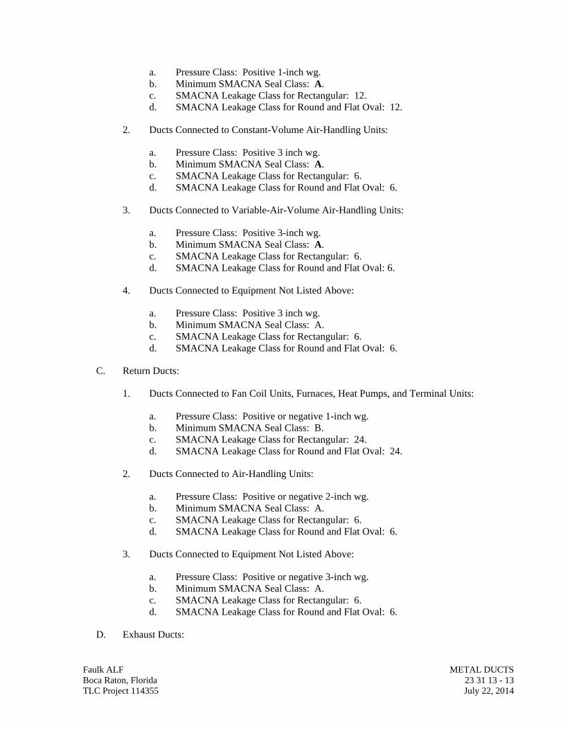
a. Pressure Class: Positive 1-inch wg. b. Minimum SMACNA Seal Class: A. c. SMACNA Leakage Class for Rectangular: 12. d. SMACNA Leakage Class for Round and Flat Oval: 12.
2. Ducts Connected to Constant-Volume Air-Handling Units:
a. Pressure Class: Positive 3 inch wg. b. Minimum SMACNA Seal Class: A. c. SMACNA Leakage Class for Rectangular: 6. d. SMACNA Leakage Class for Round and Flat Oval: 6.
3. Ducts Connected to Variable-Air-Volume Air-Handling Units:
a. Pressure Class: Positive 3-inch wg. b. Minimum SMACNA Seal Class: A. c. SMACNA Leakage Class for Rectangular: 6. d. SMACNA Leakage Class for Round and Flat Oval: 6.
4. Ducts Connected to Equipment Not Listed Above:
a. Pressure Class: Positive 3 inch wg. b. Minimum SMACNA Seal Class: A. c. SMACNA Leakage Class for Rectangular: 6. d. SMACNA Leakage Class for Round and Flat Oval: 6.
C. Return Ducts:
1. Ducts Connected to Fan Coil Units, Furnaces, Heat Pumps, and Terminal Units:
a. Pressure Class: Positive or negative 1-inch wg. b. Minimum SMACNA Seal Class: B. c. SMACNA Leakage Class for Rectangular: 24. d. SMACNA Leakage Class for Round and Flat Oval: 24.
2. Ducts Connected to Air-Handling Units:
a. Pressure Class: Positive or negative 2-inch wg. b. Minimum SMACNA Seal Class: A. c. SMACNA Leakage Class for Rectangular: 6. d. SMACNA Leakage Class for Round and Flat Oval: 6.
3. Ducts Connected to Equipment Not Listed Above:
a. Pressure Class: Positive or negative 3-inch wg. b. Minimum SMACNA Seal Class: A. c. SMACNA Leakage Class for Rectangular: 6. d. SMACNA Leakage Class for Round and Flat Oval: 6.
D. Exhaust Ducts:
Faulk ALF METAL DUCTS Boca Raton, Florida 23 31 13 - 13 TLC Project 114355 July 22, 2014
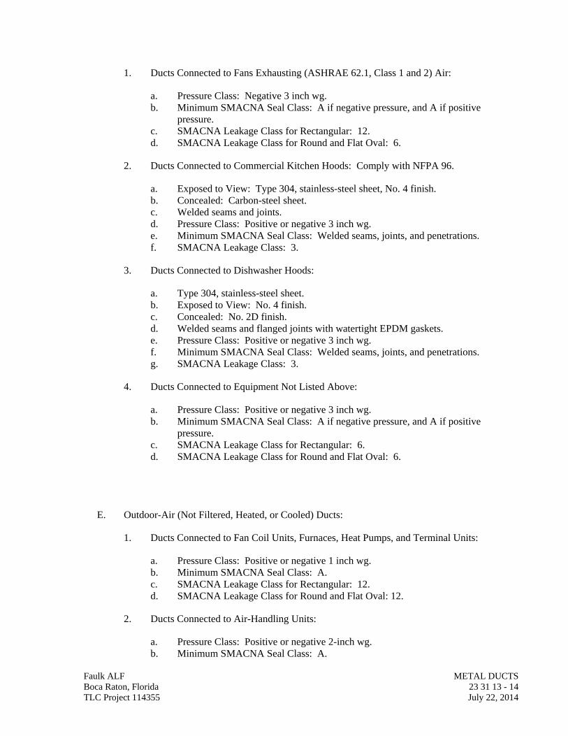
1. Ducts Connected to Fans Exhausting (ASHRAE 62.1, Class 1 and 2) Air:
a. Pressure Class: Negative 3 inch wg. b. Minimum SMACNA Seal Class: A if negative pressure, and A if positive
pressure. c. SMACNA Leakage Class for Rectangular: 12. d. SMACNA Leakage Class for Round and Flat Oval: 6.
2. Ducts Connected to Commercial Kitchen Hoods: Comply with NFPA 96.
a. Exposed to View: Type 304, stainless-steel sheet, No. 4 finish. b. Concealed: Carbon-steel sheet. c. Welded seams and joints. d. Pressure Class: Positive or negative 3 inch wg. e. Minimum SMACNA Seal Class: Welded seams, joints, and penetrations. f. SMACNA Leakage Class: 3.
3. Ducts Connected to Dishwasher Hoods:
a. Type 304, stainless-steel sheet. b. Exposed to View: No. 4 finish. c. Concealed: No. 2D finish. d. Welded seams and flanged joints with watertight EPDM gaskets. e. Pressure Class: Positive or negative 3 inch wg. f. Minimum SMACNA Seal Class: Welded seams, joints, and penetrations. g. SMACNA Leakage Class: 3.
4. Ducts Connected to Equipment Not Listed Above:
a. Pressure Class: Positive or negative 3 inch wg. b. Minimum SMACNA Seal Class: A if negative pressure, and A if positive
pressure. c. SMACNA Leakage Class for Rectangular: 6. d. SMACNA Leakage Class for Round and Flat Oval: 6.
E. Outdoor-Air (Not Filtered, Heated, or Cooled) Ducts:
1. Ducts Connected to Fan Coil Units, Furnaces, Heat Pumps, and Terminal Units:
a. Pressure Class: Positive or negative 1 inch wg. b. Minimum SMACNA Seal Class: A. c. SMACNA Leakage Class for Rectangular: 12. d. SMACNA Leakage Class for Round and Flat Oval: 12.
2. Ducts Connected to Air-Handling Units:
a. Pressure Class: Positive or negative 2-inch wg. b. Minimum SMACNA Seal Class: A.
Faulk ALF METAL DUCTS Boca Raton, Florida 23 31 13 - 14 TLC Project 114355 July 22, 2014
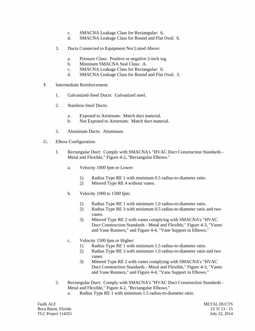
c. SMACNA Leakage Class for Rectangular: 6. d. SMACNA Leakage Class for Round and Flat Oval: 6.
3. Ducts Connected to Equipment Not Listed Above:
a. Pressure Class: Positive or negative 2-inch wg. b. Minimum SMACNA Seal Class: A. c. SMACNA Leakage Class for Rectangular: 6. d. SMACNA Leakage Class for Round and Flat Oval: 3.
F. Intermediate Reinforcement:
1. Galvanized-Steel Ducts: Galvanized steel.
2. Stainless-Steel Ducts:
a. Exposed to Airstream: Match duct material. b. Not Exposed to Airstream: Match duct material.
3. Aluminum Ducts: Aluminum.
G. Elbow Configuration:
1. Rectangular Duct: Comply with SMACNA's "HVAC Duct Construction Standards - Metal and Flexible," Figure 4-2, "Rectangular Elbows."
a. Velocity 1000 fpm or Lower:
1) Radius Type RE 1 with minimum 0.5 radius-to-diameter ratio. 2) Mitered Type RE 4 without vanes.
b. Velocity 1000 to 1500 fpm:
1) Radius Type RE 1 with minimum 1.0 radius-to-diameter ratio. 2) Radius Type RE 3 with minimum 0.5 radius-to-diameter ratio and two
vanes. 3) Mitered Type RE 2 with vanes complying with SMACNA's "HVAC
Duct Construction Standards - Metal and Flexible," Figure 4-3, "Vanes and Vane Runners," and Figure 4-4, "Vane Support in Elbows."
c. Velocity 1500 fpm or Higher: 1) Radius Type RE 1 with minimum 1.5 radius-to-diameter ratio. 2) Radius Type RE 3 with minimum 1.0 radius-to-diameter ratio and two
vanes. 3) Mitered Type RE 2 with vanes complying with SMACNA's "HVAC
Duct Construction Standards - Metal and Flexible," Figure 4-3, "Vanes and Vane Runners," and Figure 4-4, "Vane Support in Elbows."
2. Rectangular Duct: Comply with SMACNA's "HVAC Duct Construction Standards - Metal and Flexible," Figure 4-2, "Rectangular Elbows." a. Radius Type RE 1 with minimum 1.5 radius-to-diameter ratio.
Faulk ALF METAL DUCTS Boca Raton, Florida 23 31 13 - 15 TLC Project 114355 July 22, 2014
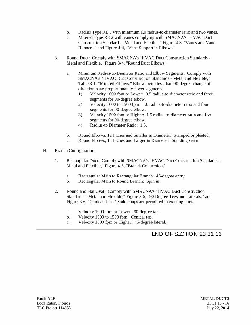
Faulk ALF METAL DUCTS Boca Raton, Florida 23 31 13 - 16 TLC Project 114355 July 22, 2014
b. Radius Type RE 3 with minimum 1.0 radius-to-diameter ratio and two vanes. c. Mitered Type RE 2 with vanes complying with SMACNA's "HVAC Duct
Construction Standards - Metal and Flexible," Figure 4-3, "Vanes and Vane Runners," and Figure 4-4, "Vane Support in Elbows."
3. Round Duct: Comply with SMACNA's "HVAC Duct Construction Standards - Metal and Flexible," Figure 3-4, "Round Duct Elbows."
a. Minimum Radius-to-Diameter Ratio and Elbow Segments: Comply with SMACNA's "HVAC Duct Construction Standards - Metal and Flexible," Table 3-1, "Mitered Elbows." Elbows with less than 90-degree change of direction have proportionately fewer segments. 1) Velocity 1000 fpm or Lower: 0.5 radius-to-diameter ratio and three
segments for 90-degree elbow. 2) Velocity 1000 to 1500 fpm: 1.0 radius-to-diameter ratio and four
segments for 90-degree elbow. 3) Velocity 1500 fpm or Higher: 1.5 radius-to-diameter ratio and five
segments for 90-degree elbow. 4) Radius-to Diameter Ratio: 1.5.
b. Round Elbows, 12 Inches and Smaller in Diameter: Stamped or pleated. c. Round Elbows, 14 Inches and Larger in Diameter: Standing seam.
H. Branch Configuration:
1. Rectangular Duct: Comply with SMACNA's "HVAC Duct Construction Standards - Metal and Flexible," Figure 4-6, "Branch Connection."
a. Rectangular Main to Rectangular Branch: 45-degree entry. b. Rectangular Main to Round Branch: Spin in.
2. Round and Flat Oval: Comply with SMACNA's "HVAC Duct Construction Standards - Metal and Flexible," Figure 3-5, "90 Degree Tees and Laterals," and Figure 3-6, "Conical Tees." Saddle taps are permitted in existing duct.
a. Velocity 1000 fpm or Lower: 90-degree tap. b. Velocity 1000 to 1500 fpm: Conical tap. c. Velocity 1500 fpm or Higher: 45-degree lateral.
END OF SECTION 23 31 13
SECTION 23 31 16
NONMETAL DUCTS
Faulk ALF NON-METAL DUCTS Boca Raton, Florida 23 31 16 - 1 TLC Project 114355 July 22, 2014
PART 1 - GENERAL
1.01 RELATED DOCUMENTS
A. Drawings and general provisions of the Contract, including General and Supplementary Conditions and Division 01 Specification Sections, apply to this Section.
1.02 SUMMARY
A. Section Includes:
1. Fibrous-glass ducts and fittings. 2. Phenolic-foam ducts and fittings. 3. Thermoset FRP ducts and fittings. 4. PVC ducts and fittings.
1.03 PERFORMANCE REQUIREMENTS
A. Delegated Duct Design: Duct construction, including duct closure, reinforcements, and hangers and supports, shall comply with SMACNA's "Fibrous Glass Duct Construction Standards" and performance requirements and design criteria indicated.
1. Static-Pressure Classes:
a. Supply Ducts (except in Mechanical Rooms): 1-inch wg . b. Supply Ducts (Downstream from Air Terminal Units): 1-inch wg . c. Supply Ducts (in Mechanical Equipment Rooms): 1-inch wg . d. Return Ducts (Negative Pressure): 1-inch wg . e. Exhaust Ducts (Negative Pressure): 1-inch wg .
B. Airstream Surfaces: Surfaces in contact with the airstream shall comply with requirements in ASHRAE 62.1.
1.04 ACTION SUBMITTALS
A. Product Data: For each type of the following products:
1. Fibrous-glass duct materials. 2. Phenolic-foam duct materials.
B. Shop Drawings:
1. Fabrication, assembly, and installation, including plans, elevations, sections, components, and attachments to other work.
2. Duct layout indicating sizes and pressure classes. 3. Elevation of top of ducts. 4. Dimensions of main duct runs from building grid lines. 5. Fittings. 6. Reinforcement and spacing.
7. Seam and joint construction. 8. Penetrations through fire-rated and other partitions. 9. Equipment installation based on equipment being used on Project. 10. Hangers and supports, including methods for duct and building attachment and
vibration isolation.
1.05 INFORMATIONAL SUBMITTALS
A. Coordination Drawings: Plans, drawn to scale, on which the following items are shown and coordinated with each other, using input from installers of the items involved:
1. Duct installation in congested spaces, indicating coordination with general construction, building components, and other building services. Indicate proposed changes to duct layout.
2. Suspended ceiling components. 3. Structural members to which duct will be attached. 4. Size and location of initial access modules for acoustical tile. 5. Penetrations of smoke barriers and fire-rated construction.
6. Items penetrating finished ceiling including the following:
a. Lighting fixtures. b. Air outlets and inlets. c. Speakers. d. Sprinklers. e. Access panels. f. Perimeter moldings.
B. Welding certificates.
C. Field quality-control reports.
1.06 QUALITY ASSURANCE
A. ASHRAE Compliance: Applicable requirements in ASHRAE 62.1, Section 5 - "Systems and Equipment" and Section 7 - "Construction and System Start-up."
B. ASHRAE/IESNA Compliance: Applicable requirements in ASHRAE/IESNA 90.1, Section 6.4.4 - "HVAC System Construction and Insulation."
C. NFPA Compliance:
1. NFPA 90A, "Installation of Air Conditioning and Ventilating Systems." 2. NFPA 90B, "Installation of Warm Air Heating and Air Conditioning Systems."
PART 2 - PRODUCTS
2.01 FIBROUS-GLASS DUCTS AND FITTINGS
A. Manufacturers: Subject to compliance with requirements, provide products by one of the following :
Faulk ALF NON-METAL DUCTS Boca Raton, Florida 23 31 16 - 2 TLC Project 114355 July 22, 2014
1. CertainTeed Corporation; Insulation Group. 2. Johns Manville. 3. Knauf Insulation. 4. Owens Corning.
B. Fibrous-Glass Duct Materials: Resin-bonded fiberglass, faced on the outside surface with fire-resistive FSK vapor retarder and with a smooth fiberglass mat finish on the air-side surface.
1. Duct Board: Factory molded into rectangular boards. 2. Round Duct: Factory molded into straight round duct and smooth fittings. 3. Temperature Limits: 40 to 250 deg F inside ducts; 150 deg F ambient temperature
surrounding ducts. 4. Maximum Thermal Conductivity: 0.24 Btu x in./h x sq. ft. x deg F at 75 deg F mean
temperature. 5. Moisture Absorption: Not exceeding 5 percent by weight at 120 deg F and 95
percent relative humidity for 96 hours when tested according to ASTM C 1104/C 1104M.
6. Permeability: 0.02 perms maximum when tested according to ASTM E 96/E 96M, Procedure A.
7. Antimicrobial Agent: Compound shall be tested for efficacy by an NRTL, and registered by the EPA for use in HVAC systems.
8. Noise-Reduction Coefficient: 0.65 minimum when tested according to ASTM C 423, Mounting A.
9. Required Markings: EI rating, UL label, and other markings required by UL 181 on each full sheet of duct board.
C. Closure Materials:
1. Two-Part Tape Sealing System: Comply with UL 181A; imprinted by the manufacturer with the coding "181A-M," the manufacturer's name, and a date code.
a. Tape: Woven glass fiber impregnated with mineral gypsum. b. Minimum Tape Width: 3 inches. c. Sealant: Modified styrene acrylic. d. Water resistant. e. Mold and mildew resistant. f. For indoor applications, sealant shall have a VOC content of 250 g/L or less
when calculated according to 40 CFR 59, Subpart D (EPA Method 24). g. Sealant shall comply with the testing and product requirements of the
California Department of Health Services' "Standard Practice for the Testing of Volatile Organic Emissions from Various Sources Using Small-Scale Environmental Chambers."
D. Fabrication:
1. Select joints, seams, transitions, elbows, and branch connections and fabricate according to SMACNA's "Fibrous Glass Duct Construction Standards," Chapter 2, "Specifications and Closure," and Chapter 4, "Fittings and Connections."
2. Fabricate 90-degree mitered elbows to include turning vanes.
Faulk ALF NON-METAL DUCTS Boca Raton, Florida 23 31 16 - 3 TLC Project 114355 July 22, 2014
3. Reinforcements: Comply with requirements in SMACNA's "Fibrous Glass Duct Construction Standards," Chapter 5, "Reinforcement" for channel- and tie-rod reinforcement materials, spacing, and fabrication.
4. Preformed Round Duct: Comply with NAIMA AH116, "Fibrous Glass Duct Construction Standards," Section VII, "Preformed Round Duct."
2.02 PHENOLIC-FOAM DUCTS AND FITTINGS
A. Manufacturers: Subject to compliance with requirements, provide products by one of the following :
1. Knauf Insulation.
B. Duct Panel: CFC-free phenolic-foam bonded on both sides with factory-applied 0.001-inch- thick, aluminum foil reinforced with fiberglass scrim.
1. Maximum Temperature: 158 deg F inside ducts or ambient temperature surrounding ducts.
2. Maximum Thermal Conductivity: 0.13 Btu x in./h x sq. ft. x deg F at 75 deg F mean temperature.
3. Permeability: 0.0002 perms maximum when tested according to ASTM E 96/E 96M, Procedure A.
4. Antimicrobial Agent: Compound shall be tested for efficacy by an NRTL, and registered by the EPA for use in HVAC systems.
5. Noise-Reduction Coefficient: 0.65 minimum when tested according to ASTM C 423, Mounting A.
6. Required Markings: UL label and other markings required by UL 181 on each full sheet of duct panel; UL ratings for closure materials.
C. Closure Materials:
1. V-Groove Adhesive: Silicone.
a. For indoor applications, sealant shall have a VOC content of 250 g/L or less when calculated according to 40 CFR 59, Subpart D (EPA Method 24).
b. Sealant shall comply with the testing and product requirements of the California Department of Health Services' "Standard Practice for the Testing of Volatile Organic Emissions from Various Sources Using Small-Scale Environmental Chambers."
2. Pressure-Sensitive Tape: Comply with UL 181A; imprinted by the manufacturer with the coding "181A-P," the manufacturer's name, and a date code.
a. Tape: Aluminum foil tape imprinted with listing information. b. Minimum Tape Width: 3 inches. c. Water resistant. d. Mold and mildew resistant.
Faulk ALF NON-METAL DUCTS Boca Raton, Florida 23 31 16 - 4 TLC Project 114355 July 22, 2014
3. Polymeric Sealing System:
a. Structural Membrane: Woven glass fiber. b. Minimum Tape Width: 3 inches. c. Sealant: Water based. d. Color: White. e. Water resistant. f. Mold and mildew resistant. g. For indoor applications, sealant shall have a VOC content of 250 g/L or less
when calculated according to 40 CFR 59, Subpart D (EPA Method 24). h. Sealant shall comply with the testing and product requirements of the
California Department of Health Services' "Standard Practice for the Testing of Volatile Organic Emissions from Various Sources Using Small-Scale Environmental Chambers."
D. Fabrication:
1. Fabricate joints, seams, transitions, reinforcement, elbows, branch connections, access doors and panels, and damage repairs according to Knauf Insulation's "Knauf KoolDuct System Design Guide," Section 4, "Duct Construction," and Section 5, "Ductwork System General."
2. Fabricate 90-degree mitered elbows to include turning vanes.
2.03 HANGERS AND SUPPORTS
A. Hanger Rods for Noncorrosive Environments: Cadmium-plated steel rods and nuts.
B. Hanger Rods for Corrosive Environments: Electrogalvanized, all-thread rods or galvanized rods with threads painted with zinc-chromate primer after installation.
C. Strap and Rod Sizes: Comply with SMACNA's "HVAC Duct Construction Standards - Metal and Flexible," Table 5-1, "Rectangular Duct Hangers Minimum Size," and Table 5-2, "Minimum Hanger Sizes for Round Duct."
D. Steel Cables: ASTM A 603, galvanized steel with end connections made of cadmium-plated steel assemblies with brackets, swivel, and bolts designed for duct hanger service; with an automatic-locking and clamping device.
E. Duct Attachments: Sheet metal screws, blind rivets, or self-tapping metal screws; compatible with duct materials.
F. Trapeze and Riser Supports: Steel shapes complying with ASTM A 36/A 36M.
PART 3 - EXECUTION
3.01 DUCT INSTALLATION
A. Install ducts with fewest possible joints.
Faulk ALF NON-METAL DUCTS Boca Raton, Florida 23 31 16 - 5 TLC Project 114355 July 22, 2014
B. Unless otherwise indicated, install ducts vertically and horizontally, and parallel and perpendicular to building lines.
C. Install ducts close to walls, overhead construction, columns, and other structural and permanent enclosure elements of building.
D. Install ducts with a clearance of 1 inch, plus allowance for insulation thickness.
E. Where ducts pass through non-fire-rated interior partitions and exterior walls and are exposed to view, cover the opening between the partition and duct or duct insulation with sheet metal flanges. Overlap openings on four sides by at least 1-1/2 inches.
F. Where ducts pass through fire-rated interior partitions and exterior walls, install fire dampers. Comply with requirements in Division 23 Section "Air Duct Accessories" for fire and smoke dampers.
G. Protect duct interiors from the moisture, construction debris and dust, and other foreign materials. Comply with SMACNA's "IAQ Guidelines for Occupied Buildings Under Construction," Appendix G, "Duct Cleanliness for New Construction Guidelines."
H. Install fibrous-glass ducts and fittings to comply with SMACNA's "Fibrous Glass Duct Construction Standards."
I. Install foam ducts and fittings to comply with Knauf Insulation's "Knauf KoolDuct System Design Guide."
J. Install thermoset FRP ducts and fittings to comply with SMACNA's "Thermoset FRP Duct Construction Manual."
K. Install PVC ducts and fittings to comply with SMACNA's "Thermoplastic Duct (PVC) Construction Manual."
3.02 HANGER AND SUPPORT INSTALLATION
A. Install hangers and supports for fibrous-glass ducts and fittings to comply with SMACNA's "Fibrous Glass Duct Construction Standards," Chapter 6, "Hangers and Supports."
B. Install hangers and supports for phenolic-foam ducts and fittings to comply with Knauf Insulation's "Knauf KoolDuct System Design Guide," Section 5, "Ductwork System General."
C. Install hangers and supports for thermoset FRP ducts and fittings to comply with SMACNA's "Thermoset FRP Duct Construction Manual," Chapter 7, "Requirements."
D. Install hangers and supports for PVC ducts and fittings to comply with SMACNA's "Thermoplastic Duct (PVC) Construction Manual," Chapter 3, "Standards of Construction for PVC Duct Systems."
E. Building Attachments: Concrete inserts, powder-actuated fasteners, or structural-steel fasteners appropriate for construction materials to which hangers are being attached.
1. Install concrete inserts before placing concrete. Faulk ALF NON-METAL DUCTS Boca Raton, Florida 23 31 16 - 6 TLC Project 114355 July 22, 2014
2. Install powder-actuated concrete fasteners after concrete is placed and completely cured.
3. Use powder-actuated concrete fasteners for standard-weight aggregate concretes or for slabs more than 4 inches thick.
4. Do not use powder-actuated concrete fasteners for lightweight-aggregate concretes or for slabs less than 4 inches thick.
5. Do not use powder-actuated concrete fasteners for seismic restraints.
F. Install upper attachments to structures. Select and size upper attachments with pull-out, tension, and shear capacities appropriate for supported loads and building materials where used.
3.03 FIELD QUALITY CONTROL
A. Perform tests and inspections.
B. Leakage Tests:
1. Comply with SMACNA's "HVAC Air Duct Leakage Test Manual." Submit a test report for each test.
2. Test the following systems:
a. Ducts with a Pressure Class Higher Than 3-Inch wg: Test representative duct sections totaling no less than 25 percent of total installed duct area for each designated pressure class.
b. Supply Ducts with a Pressure Class of 3-Inch wg or Higher: Test representative duct sections totaling no less than 50 percent of total installed duct area for each designated pressure class.
c. Return Ducts with a Pressure Class of 3-Inch wg or Higher: Test representative duct sections totaling no less than 50 percent of total installed duct area for each designated pressure class.
d. Exhaust Ducts with a Pressure Class of 3-Inch wg or Higher: Test representative duct sections totaling no less than 50 percent of total installed duct area for each designated pressure class.
e. Outdoor Air Ducts with a Pressure Class of 3-Inch wg or Higher: Test representative duct sections totaling no less than 50 percent of total installed duct area for each designated pressure class.
3. Disassemble, reassemble, and seal segments of systems to accommodate leakage testing and for compliance with test requirements.
4. Test for leaks before applying external insulation.
5. Conduct tests at static pressures equal to maximum design pressure of system or section being tested. If static-pressure classes are not indicated, test entire system at
Faulk ALF NON-METAL DUCTS Boca Raton, Florida 23 31 16 - 7 TLC Project 114355 July 22, 2014
maximum system design pressure. Do not pressurize systems above maximum design operating pressure. Give seven days' advance notice for testing.
C. Duct System Cleanliness Tests:
1. Visually inspect duct system to ensure that no visible contaminants are present.
2. Test sections of nonmetal duct system, chosen randomly by Owner, for cleanliness according to "Vacuum Test" in NADCA ACR, "Assessment, Cleaning and Restoration of HVAC Systems."
a. Acceptable Cleanliness Level: Net weight of debris collected on the filter media shall not exceed 0.75 mg/100 sq. cm.
D. Duct system will be considered defective if it does not pass tests and inspections.
E. Prepare test and inspection reports.
3.04 DUCT CLEANING
A. Clean new and existing duct system(s) before testing, adjusting, and balancing.
B. Use service openings for entry and inspection.
1. Create new openings and install access panels appropriate for duct static-pressure class if required for cleaning access. Provide insulated panels for insulated or lined duct. Patch duct as recommended by duct manufacturer. Comply with Division 23 Section "Air Duct Accessories" for access panels and doors.
2. Disconnect and reconnect flexible ducts as needed for cleaning and inspection.
3. Remove and reinstall ceiling to gain access during the cleaning process.
C. Particulate Collection and Odor Control:
1. When venting vacuuming system inside the building, use HEPA filtration with 99.97 percent collection efficiency for 0.3-micron-size (or larger) particles.
2. When venting vacuuming system to outdoors, use filter to collect debris removed from HVAC system, and locate exhaust downwind and away from air intakes and other points of entry into building.
D. Clean the following components by removing surface contaminants and deposits:
1. Air outlets and inlets (registers, grilles, and diffusers).
2. Supply, return, and exhaust fans including fan housings, plenums (except ceiling supply and return plenums), scrolls, blades or vanes, shafts, baffles, dampers, and drive assemblies.
Faulk ALF NON-METAL DUCTS Boca Raton, Florida 23 31 16 - 8 TLC Project 114355 July 22, 2014
3. Air-handling unit internal surfaces and components including mixing box, coil section, air wash systems, spray eliminators, condensate drain pans, humidifiers and dehumidifiers, filters and filter sections, and condensate collectors and drains.
4. Coils and related components.
5. Return-air ducts, dampers, actuators, and turning vanes except in ceiling plenums and mechanical equipment rooms.
6. Supply-air ducts, dampers, actuators, and turning vanes.
7. Dedicated exhaust and ventilation components and makeup air systems.
E. Mechanical Cleaning Methodology:
1. Use vacuum-collection devices that are operated continuously during cleaning. Connect vacuum device to downstream end of duct sections so areas being cleaned are under negative pressure.
2. Use mechanical agitation to dislodge debris adhered to interior duct surfaces without damaging integrity of ducts or duct accessories.
3. Clean fibrous-glass duct with HEPA vacuuming equipment; do not permit duct to get wet. Replace fibrous-glass duct that is damaged, deteriorated, or delaminated or that has friable material, mold, or fungus growth.
4. Clean coils and coil drain pans according to NADCA 1992. Keep drain pan operational. Rinse coils with clean water to remove latent residues and cleaning materials; comb and straighten fins.
5. Provide drainage and cleanup for wash-down procedures.
6. Antimicrobial Agents and Coatings: Apply EPA-registered antimicrobial agents if fungus is present. Apply antimicrobial agents according to manufacturer's written instructions after removal of surface deposits and debris.
3.05 START UP
A. Air Balance: Comply with requirements in Division 23 Section "Testing, Adjusting, and Balancing for HVAC."
3.06 DUCT SCHEDULE
A. Indoor Ducts and Fittings:
1. Fibrous-Glass Rectangular Ducts and Fittings:
a. Minimum Flexural Rigidity: EI- 1400. b. Minimum Board Thickness: 1-1/2 inches .
Faulk ALF NON-METAL DUCTS Boca Raton, Florida 23 31 16 - 9 TLC Project 114355 July 22, 2014
Faulk ALF NON-METAL DUCTS Boca Raton, Florida 23 31 16 - 10 TLC Project 114355 July 22, 2014
2. Fibrous-Glass Round Ducts and Fittings:
a. Minimum Thickness: 1 inch .
3. Phenolic-Foam Rectangular Ducts and Fittings:
a. Minimum Panel Thickness: 7/8 inch or 1-3/32 inches. b. Aluminum Cladding: Minimum 0.025 inch thick.
B. Outdoor Ducts and Fittings:
1. Phenolic-Foam Rectangular Ducts and Fittings:
a. Minimum Panel Thickness: 7/8 inch or 1-3/32 inches.
b. Aluminum Cladding: Minimum 0.032 inch thick.
c. Polymeric Sealing System: Coat ducts, including gang-nail couplings, grip flanges, and couplings.
END OF SECTION 23 31 16
SECTION 23 33 00
AIR DUCT ACCESSORIES
Faulk ALF AIR DUCT ACCESSORIES Boca Raton, Florida 23 33 00 - 1 TLC Project 114355 July 22, 2014
PART 1 - GENERAL
1.01 RELATED DOCUMENTS
A. Drawings and general provisions of the Contract, including General and Supplementary Conditions and Division 01 Specification Sections, apply to this Section.
1.02 SUMMARY
A. Section Includes:
1. Backdraft and pressure relief dampers. 2. Barometric relief dampers. 3. Manual volume dampers. 4. Control dampers. 5. Fire dampers. 6. Ceiling dampers. 7. Combination fire and smoke dampers. 8. Flange connectors. 9. Turning vanes. 10. Remote damper operators. 11. Duct-mounted access doors. 12. Flexible connectors. 13. Flexible ducts. 14. Duct accessory hardware.
1.03 ACTION SUBMITTALS
A. Product Data: For each type of product indicated.
1. For duct silencers, include pressure drop and dynamic insertion loss data. Include breakout noise calculations for high transmission loss casings.
B. Shop Drawings: For duct accessories. Include plans, elevations, sections, details and attachments to other work.
1. Detail duct accessories fabrication and installation in ducts and other construction. Include dimensions, weights, loads, and required clearances; and method of field assembly into duct systems and other construction. Include the following:
a. Special fittings. b. Manual volume damper installations. c. Control damper installations. d. Fire-damper, smoke-damper, combination fire- and smoke-damper, ceiling,
and corridor damper installations, including sleeves; and duct-mounted access doors and remote damper operators.
e. Duct security bars. f. Wiring Diagrams: For power, signal, and control wiring.
1.04 INFORMATIONAL SUBMITTALS
A. Coordination Drawings: Reflected ceiling plans, drawn to scale, on which ceiling-mounted access panels and access doors required for access to duct accessories are shown and coordinated with each other, using input from Installers of the items involved.
B. Source quality-control reports.
1.05 CLOSEOUT SUBMITTALS
A. Operation and Maintenance Data: For air duct accessories to include in operation and maintenance manuals.
1.06 MAINTENANCE MATERIAL SUBMITTALS
A. Furnish extra materials that match products installed and that are packaged with protective covering for storage and identified with labels describing contents.
1. Fusible Links: Furnish quantity equal to 10 percent of amount installed.
1.07 QUALITY ASSURANCE
A. Comply with NFPA 90A, "Installation of Air Conditioning and Ventilating Systems," and with NFPA 90B, "Installation of Warm Air Heating and Air Conditioning Systems."
B. Comply with AMCA 500-D testing for damper rating.
PART 2 - PRODUCTS
2.01 MATERIALS
A. Comply with SMACNA's "HVAC Duct Construction Standards - Metal and Flexible" for acceptable materials, material thicknesses, and duct construction methods unless otherwise indicated. Sheet metal materials shall be free of pitting, seam marks, roller marks, stains, discolorations, and other imperfections.
B. Galvanized Sheet Steel: Comply with ASTM A 653/A 653M.
1. Galvanized Coating Designation: G60. 2. Exposed-Surface Finish: Mill phosphatized.
C. Stainless-Steel Sheets: Comply with ASTM A 480/A 480M, Type 304, and having a No. 2 finish for concealed ducts and No. 2 finish for exposed ducts.
D. Aluminum Sheets: Comply with ASTM B 209, Alloy 3003, Temper H14; with mill finish for concealed ducts and standard, 1-side bright finish for exposed ducts.
E. Extruded Aluminum: Comply with ASTM B 221, Alloy 6063, Temper T6.
F. Reinforcement Shapes and Plates: Galvanized-steel reinforcement where installed on galvanized sheet metal ducts; compatible materials for aluminum and stainless-steel ducts.
Faulk ALF AIR DUCT ACCESSORIES Boca Raton, Florida 23 33 00 - 2 TLC Project 114355 July 22, 2014
G. Tie Rods: Galvanized steel, 1/4-inch minimum diameter for lengths 36 inches or less; 3/8-inch minimum diameter for lengths longer than 36 inches.
2.02 BACKDRAFT AND PRESSURE RELIEF DAMPERS
A. Manufacturers: Subject to compliance with requirements, provide products by one of the following:
1. Air Balance Inc.; a division of Mestek, Inc. 2. American Warming and Ventilating; a division of Mestek, Inc. 3. Cesco Products; a division of Mestek, Inc. 4. Duro Dyne Inc. 5. Greenheck Fan Corporation. 6. Lloyd Industries, Inc. 7. Nailor Industries Inc. 8. NCA Manufacturing, Inc. 9. Ruskin Company. 10. SEMCO Incorporated. 11. Vent Products Company, Inc.
B. Description: Gravity balanced.
C. Maximum Air Velocity: 3000 fpm.
D. Maximum System Pressure: 2 inch wg.
E. Frame: 0.052-inch- thick, galvanized sheet steel, with welded corners and mounting flange.
F. Blades: Multiple single-piece blades, center pivoted, maximum 6-inch width, 0.025 inch thick, roll-formed aluminum with sealed edges.
G. Blade Action: Parallel.
H. Blade Seals: Felt.
I. Blade Axles:
1. Material: Non-metallic. 2. Diameter: 0.20 inch.
J. Tie Bars and Brackets: Aluminum.
K. Return Spring: Adjustable tension.
L. Bearings: Synthetic pivot bushings.
M. Accessories:
1. Adjustment device to permit setting for varying differential static pressure. 2. Counterweights and spring-assist kits for vertical airflow installations. 3. Electric actuators. 4. Chain pulls.
Faulk ALF AIR DUCT ACCESSORIES Boca Raton, Florida 23 33 00 - 3 TLC Project 114355 July 22, 2014
5. Screen Mounting: Front mounted in sleeve.
a. Sleeve Thickness: 20-gage minimum. b. Sleeve Length: 6 inches minimum.
6. Screen Mounting: Rear mounted. 7. Screen Material: Galvanized steel. 8. Screen Type: Bird. 9. 90-degree stops.
2.03 BAROMETRIC RELIEF DAMPERS
A. Manufacturers: Subject to compliance with requirements, provide products by one of the following:
1. Air Balance Inc.; a division of Mestek, Inc. 2. American Warming and Ventilating; a division of Mestek, Inc. 3. Cesco Products; a division of Mestek, Inc. 4. Duro Dyne Inc. 5. Greenheck Fan Corporation. 6. Lloyd Industries, Inc. 7. Nailor Industries Inc. 8. NCA Manufacturing, Inc. 9. Ruskin Company. 10. SEMCO Incorporated. 11. Vent Products Company, Inc.
B. Suitable for horizontal or vertical mounting.
C. Maximum Air Velocity: 2000 fpm.
D. Maximum System Pressure: 2-inch wg.
E. Frame: 0.064-inch- thick, galvanized sheet steel.
F. Blades:
1. Multiple, 0.025-inch- thick, roll-formed aluminum. 2. Maximum Width: 6 inches. 3. Action: Parallel. 4. Balance: Gravity. 5. Eccentrically pivoted.
G. Blade Seals: Vinyl.
H. Blade Axles: Nonferrous metal.
I. Tie Bars and Brackets:
1. Material: Aluminum. 2. Rattle free with 90-degree stop.
Faulk ALF AIR DUCT ACCESSORIES Boca Raton, Florida 23 33 00 - 4 TLC Project 114355 July 22, 2014
J. Return Spring: Adjustable tension.
K. Bearings: Synthetic.
L. Accessories:
1. Flange on intake. 2. Adjustment device to permit setting for varying differential static pressures.
2.04 MANUAL VOLUME DAMPERS
A. Standard, Steel, Manual Volume Dampers:
1. Manufacturers: Subject to compliance with requirements, provide products by one of the following:
a. Air Balance Inc.; a division of Mestek, Inc. b. American Warming and Ventilating; a division of Mestek, Inc. c. Flexmaster U.S.A., Inc. d. McGill AirFlow LLC. e. METALAIRE, Inc. f. Nailor Industries Inc. g. Ruskin Company. h. Trox USA Inc. i. Vent Products Company, Inc.
2. Standard leakage rating, with linkage outside airstream.
3. Suitable for horizontal or vertical applications.
4. Frames:
a. Hat-shaped, galvanized steel channels, 0.064-inch minimum thickness. b. Mitered and welded corners. c. Flanges for attaching to walls and flangeless frames for installing in ducts.
5. Blades:
a. Multiple or single blade. b. Parallel- or opposed-blade design. c. Stiffen damper blades for stability. d. Galvanized steel, 0.064 inch thick.
6. Blade Axles: Nonferrous metal.
7. Bearings:
a. Oil-impregnated bronze.
b. Dampers in ducts with pressure classes of 3-inch wg or less shall have axles full length of damper blades and bearings at both ends of operating shaft.
Faulk ALF AIR DUCT ACCESSORIES Boca Raton, Florida 23 33 00 - 5 TLC Project 114355 July 22, 2014
8. Tie Bars and Brackets: Galvanized steel.
B. Standard, Aluminum, Manual Volume Dampers:
1. Manufacturers: Subject to compliance with requirements, provide products by one of the following:
a. Air Balance Inc.; a division of Mestek, Inc. b. American Warming and Ventilating; a division of Mestek, Inc. c. Flexmaster U.S.A., Inc. d. McGill AirFlow LLC. e. METALAIRE, Inc. f. Nailor Industries Inc. g. Ruskin Company. h. Trox USA Inc. i. Vent Products Company, Inc.
2. Standard leakage rating, with linkage outside airstream.
3. Suitable for horizontal or vertical applications.
4. Frames: Hat-shaped, 0.10-inch- thick, aluminum sheet channels; frames with flanges for attaching to walls and flangeless frames for installing in ducts.
5. Blades:
a. Multiple or single blade. b. Parallel- or opposed-blade design. c. Stiffen damper blades for stability. d. Roll-Formed Aluminum Blades: 0.10-inch- thick aluminum sheet. e. Extruded-Aluminum Blades: 0.050-inch- thick extruded aluminum.
6. Blade Axles: Nonferrous metal.
7. Bearings:
a. Oil-impregnated bronze. b. Dampers in ducts with pressure classes of 3-inch wg or less shall have axles
full length of damper blades and bearings at both ends of operating shaft.
8. Tie Bars and Brackets: Aluminum.
C. Low-Leakage, Steel, Manual Volume Dampers:
1. Manufacturers: Subject to compliance with requirements, provide products by one of the following:
a. Air Balance Inc.; a division of Mestek, Inc. b. American Warming and Ventilating; a division of Mestek, Inc. c. Flexmaster U.S.A., Inc. d. McGill AirFlow LLC.
Faulk ALF AIR DUCT ACCESSORIES Boca Raton, Florida 23 33 00 - 6 TLC Project 114355 July 22, 2014
e. METALAIRE, Inc. f. Nailor Industries Inc. g. Ruskin Company. h. Trox USA Inc. i. Vent Products Company, Inc.
2. Low-leakage rating, with linkage outside airstream, and bearing AMCA's Certified Ratings Seal for both air performance and air leakage.
3. Suitable for horizontal or vertical applications.
4. Frames:
a. Hat shaped. b. Galvanized steel channels, 0.064 inch thick. c. Mitered and welded corners. d. Flanges for attaching to walls and flangeless frames for installing in ducts.
5. Blades:
a. Multiple or single blade. b. Parallel- or opposed-blade design. c. Stiffen damper blades for stability. d. Galvanized roll-formed steel, 0.064 inch thick.
6. Blade Axles: Nonferrous metal.
7. Bearings:
a. Oil-impregnated bronze. b. Dampers in ducts with pressure classes of 3-inch wg or less shall have axles
full length of damper blades and bearings at both ends of operating shaft.
8. Blade Seals: Felt.
9. Jamb Seals: Cambered aluminum.
10. Tie Bars and Brackets: Aluminum.
11. Accessories:
a. Include locking device to hold single-blade dampers in a fixed position without vibration.
D. Low-Leakage, Aluminum, Manual Volume Dampers:
1. Manufacturers: Subject to compliance with requirements, provide products by one of the following:
a. Air Balance Inc.; a division of Mestek, Inc. b. American Warming and Ventilating; a division of Mestek, Inc. c. Flexmaster U.S.A., Inc.
Faulk ALF AIR DUCT ACCESSORIES Boca Raton, Florida 23 33 00 - 7 TLC Project 114355 July 22, 2014
d. McGill AirFlow LLC. e. METALAIRE, Inc. f. Nailor Industries Inc. g. Ruskin Company. h. Trox USA Inc. i. Vent Products Company, Inc.
2. Low-leakage rating, with linkage outside airstream, and bearing AMCA's Certified Ratings Seal for both air performance and air leakage.
3. Suitable for horizontal or vertical applications.
4. Frames: Hat shaped, 0.10-inch- thick, aluminum sheet channels; frames with flanges for attaching to walls and flangeless frames for installing in ducts.
5. Blades:
a. Multiple or single blade. b. Parallel- or opposed-blade design. c. Roll-Formed Aluminum Blades: 0.10-inch- thick aluminum sheet. d. Extruded-Aluminum Blades: 0.050-inch- thick extruded aluminum.
6. Blade Axles: Nonferrous metal.
7. Bearings:
a. Oil-impregnated bronze. b. Dampers in ducts with pressure classes of 3-inch wg or less shall have axles
full length of damper blades and bearings at both ends of operating shaft.
8. Blade Seals: Felt.
9. Jamb Seals: Cambered aluminum.
10. Tie Bars and Brackets: Aluminum.
11. Accessories:
a. Include locking device to hold single-blade dampers in a fixed position without vibration.
E. Jackshaft:
1. Size: 1-inch diameter.
2. Material: Galvanized-steel pipe rotating within pipe-bearing assembly mounted on supports at each mullion and at each end of multiple-damper assemblies.
3. Length and Number of Mountings: As required to connect linkage of each damper in multiple-damper assembly.
Faulk ALF AIR DUCT ACCESSORIES Boca Raton, Florida 23 33 00 - 8 TLC Project 114355 July 22, 2014

F. Damper Hardware:
1. Zinc-plated, die-cast core with dial and handle made of 3/32 inch thick zinc plated steel, and a 3/4-inch hexagon locking nut.
2. Include center hole to suit damper operating-rod size. 3. Include elevated platform for insulated duct mounting.
2.05 CONTROL DAMPERS
A. Manufacturers: Subject to compliance with requirements, provide products by one of the following:
1. American Warming and Ventilating; a division of Mestek, Inc. 2. Arrow United Industries; a division of Mestek, Inc. 3. Cesco Products; a division of Mestek, Inc. 4. Duro Dyne Inc. 5. Flexmaster U.S.A., Inc. 6. Greenheck Fan Corporation. 7. Lloyd Industries, Inc. 8. M&I Air Systems Engineering; Division of M&I Heat Transfer Products Ltd. 9. McGill AirFlow LLC. 10. METALAIRE, Inc. 11. Metal Form Manufacturing, Inc. 12. Nailor Industries Inc. 13. NCA Manufacturing, Inc. 14. Ruskin Company. 15. Vent Products Company, Inc. 16. Young Regulator Company.
B. Low-leakage rating, with linkage outside airstream, and bearing AMCA's Certified Ratings Seal for both air performance and air leakage.
C. Frames:
1. Hat shaped. 2. Galvanized steel channels, 0.064 inch thick. 3. Mitered and welded corners.
D. Blades:
1. Multiple blade with maximum blade width of 8 inches. 2. Parallel and opposed blade design. 3. Galvanized steel. 4. 0.064 inch thick. 5. Blade Edging: Closed-cell neoprene edging. 6. Blade Edging: Inflatable seal blade edging, or replaceable rubber seals.
E. Blade Axles: ½ inch diameter; stainless steel; blade-linkage hardware of zinc-plated steel and brass; ends sealed against blade bearings.
1. Operating Temperature Range: From minus 40 to plus 200 deg F.
Faulk ALF AIR DUCT ACCESSORIES Boca Raton, Florida 23 33 00 - 9 TLC Project 114355 July 22, 2014
F. Bearings:
1. Oil impregnated bronze. 2. Dampers in ducts with pressure classes of 3-inch wg or less shall have axles full
length of damper blades and bearings at both ends of operating shaft. 3. Thrust bearings at each end of every blade.
2.06 FIRE DAMPERS
A. Manufacturers: Subject to compliance with requirements, provide products by one of the following:
1. Air Balance Inc.; a division of Mestek, Inc. 2. Arrow United Industries; a division of Mestek, Inc. 3. Cesco Products; a division of Mestek, Inc. 4. Greenheck Fan Corporation. 5. McGill AirFlow LLC. 6. METALAIRE, Inc. 7. Nailor Industries Inc. 8. NCA Manufacturing, Inc. 9. PHL, Inc. 10. Prefco; Perfect Air Control, Inc. 11. Ruskin Company. 12. Vent Products Company, Inc. 13. Ward Industries, Inc.; a division of Hart & Cooley, Inc.
B. Type: Dynamic; rated and labeled according to UL 555 by an NRTL.
C. Closing rating in ducts up to 4-inch wg static pressure class and maximum 4000-fpm velocity.
D. Fire Rating: 1-1/2 and 3 hours.
E. Frame: Curtain type with blades outside airstream except when located behind grille where blades may be inside airstream; fabricated with roll-formed, 0.034-inch- thick galvanized steel; with mitered and interlocking corners.
F. Mounting Sleeve: Factory- or field-installed, galvanized sheet steel.
1. Minimum Thickness: 0.052 or 0.138 inch thick, as indicated, and of length to suit application.
2. Exception: Omit sleeve where damper-frame width permits direct attachment of perimeter mounting angles on each side of wall or floor; thickness of damper frame must comply with sleeve requirements.
G. Mounting Orientation: Vertical or horizontal as indicated.
H. Blades: Roll-formed, interlocking, 0.034-inch- thick, galvanized sheet steel. In place of interlocking blades, use full-length, 0.034-inch- thick, galvanized-steel blade connectors.
Faulk ALF AIR DUCT ACCESSORIES Boca Raton, Florida 23 33 00 - 10 TLC Project 114355 July 22, 2014
I. Horizontal Dampers: Include blade lock and stainless-steel closure spring.
J. Heat-Responsive Device: Replaceable, 212 deg F rated, fusible links.
K. Heat-Responsive Device: Electric resettable link and switch package, factory installed, 212 deg F rated.
2.07 CEILING DAMPERS
A. Manufacturers: Subject to compliance with requirements, provide products by one of the following:
1. Air Balance Inc.; a division of Mestek, Inc. 2. Cesco Products; a division of Mestek, Inc. 3. McGill AirFlow LLC. 4. METALAIRE, Inc. 5. Nailor Industries Inc. 6. Prefco; Perfect Air Control, Inc. 7. Ruskin Company. 8. Vent Products Company, Inc. 9. Ward Industries, Inc.; a division of Hart & Cooley, Inc.
B. General Requirements:
1. Labeled according to UL 555C by an NRTL.
2. Comply with construction details for tested floor- and roof-ceiling assemblies as indicated in UL's "Fire Resistance Directory."
C. Frame: Galvanized sheet steel, round or rectangular, style to suit ceiling construction.
D. Blades: Galvanized sheet steel with refractory insulation.
E. Heat-Responsive Device: Replaceable, 212 deg F rated, fusible links.
F. Fire Rating: 2 hours.
2.08 COMBINATION FIRE AND SMOKE DAMPERS
A. Manufacturers: Subject to compliance with requirements, provide products by one of the following:
1. Air Balance Inc.; a division of Mestek, Inc. 2. Cesco Products; a division of Mestek, Inc. 3. Greenheck Fan Corporation. 4. Nailor Industries Inc. 5. Ruskin Company.
B. Type: Dynamic; rated and labeled according to UL 555 and UL 555S by an NRTL.
Faulk ALF AIR DUCT ACCESSORIES Boca Raton, Florida 23 33 00 - 11 TLC Project 114355 July 22, 2014
C. Closing rating in ducts up to 4-inch wg static pressure class and maximum 4000-fpm velocity.
D. Fire Rating: 1-1/2 and 3 hours.
E. Frame: Multiple-blade type; fabricated with roll-formed, 0.034-inch- thick galvanized steel; with mitered and interlocking corners.
F. Heat-Responsive Device: Replaceable, 212 deg F rated, fusible links.
G. Heat-Responsive Device: Electric resettable link and switch package, factory installed, rated.
H. Smoke Detector: Integral, factory wired for single-point connection.
I. Blades: Roll-formed, horizontal, interlocking, 0.034-inch- thick, galvanized sheet steel. In place of interlocking blades, use full-length, 0.034-inch- thick, galvanized-steel blade connectors.
J. Leakage: Class I.
K. Rated pressure and velocity to exceed design airflow conditions.
L. Mounting Sleeve: Factory-installed, 0.052-inch- thick, galvanized sheet steel; length to suit wall or floor application with factory-furnished silicone calking.
M. Master control panel for use in dynamic smoke-management systems.
N. Damper Motors: Modulating or two-position action.
O. Comply with NEMA designation, temperature rating, service factor, enclosure type, and efficiency requirements for motors specified in Division 23 Section "Common Motor Requirements for HVAC Equipment."
1. Motor Sizes: Minimum size as indicated. If not indicated, large enough so driven load will not require motor to operate in service factor range above 1.0.
2. Controllers, Electrical Devices, and Wiring: Comply with requirements for electrical devices and connections specified in Division 23 Section "Instrumentation and Control for HVAC".
3. Permanent-Split-Capacitor or Shaded-Pole Motors: With oil-immersed and sealed gear trains.
4. Spring-Return Motors: Equip with an integral spiral-spring mechanism where indicated. Enclose entire spring mechanism in a removable housing designed for service or adjustments. Size for running torque rating of 150 in. x lbf and breakaway torque rating of 150 in. x lbf.
5. Outdoor Motors and Motors in Outdoor-Air Intakes: Equip with O-ring gaskets designed to make motors weatherproof. Equip motors with internal heaters to permit normal operation at minus 40 deg F.
Faulk ALF AIR DUCT ACCESSORIES Boca Raton, Florida 23 33 00 - 12 TLC Project 114355 July 22, 2014
6. Nonspring-Return Motors: For dampers larger than 25 sq. ft., size motor for running torque rating of 150 in. x lbf and breakaway torque rating of 300 in. x lbf.
7. Electrical Connection: 115 V, single phase, 60 Hz.
2.09 FLANGE CONNECTORS
A. Manufacturers: Subject to compliance with requirements, provide products by one of the following:
1. Ductmate Industries, Inc. 2. Nexus PDQ; Division of Shilco Holdings Inc. 3. Ward Industries, Inc.; a division of Hart & Cooley, Inc.
B. Description: Add on or roll formed, factory fabricated, slide-on transverse flange connectors, gaskets, and components.
C. Material: Galvanized steel.
D. Gage and Shape: Match connecting ductwork.
2.10 TURNING VANES
A. Manufacturers: Subject to compliance with requirements, provide products by one of the following:
1. Ductmate Industries, Inc. 2. Duro Dyne Inc. 3. METALAIRE, Inc. 4. SEMCO Incorporated. 5. Ward Industries, Inc.; a division of Hart & Cooley, Inc.
B. Manufactured Turning Vanes for Metal Ducts: Curved blades of galvanized sheet steel; support with bars perpendicular to blades set; set into vane runners suitable for duct mounting.
1. Acoustic Turning Vanes: Fabricate airfoil-shaped aluminum extrusions with perforated faces and fibrous-glass fill.
C. Manufactured Turning Vanes for Nonmetal Ducts: Fabricate curved blades of resin-bonded fiberglass with acrylic polymer coating; support with bars perpendicular to blades set; set into vane runners suitable for duct mounting.
D. General Requirements: Comply with SMACNA's "HVAC Duct Construction Standards - Metal and Flexible"; Figures 4-3, "Vanes and Vane Runners," and 4-4, "Vane Support in Elbows."
E. Vane Construction: Single wall.
F. Vane Construction: Single wall for ducts up to 48 inches wide and double wall for larger dimensions.
Faulk ALF AIR DUCT ACCESSORIES Boca Raton, Florida 23 33 00 - 13 TLC Project 114355 July 22, 2014
2.11 REMOTE DAMPER OPERATORS
A. Manufacturers: Subject to compliance with requirements, provide products by one of the following:
1. Ventfabrics, Inc. 2. Young Regulator Company.
B. Description: Cable system designed for remote manual damper adjustment.
C. Tubing: Brass.
D. Cable: Stainless steel.
E. Wall-Box Mounting: Recessed, 3/4 inches deep.
F. Wall-Box Cover-Plate Material: Stainless steel.
2.12 DUCT-MOUNTED ACCESS DOORS
A. Manufacturers: Subject to compliance with requirements, provide products by one of the following:
1. American Warming and Ventilating; a division of Mestek, Inc. 2. Cesco Products; a division of Mestek, Inc. 3. Ductmate Industries, Inc. 4. Flexmaster U.S.A., Inc. 5. Greenheck Fan Corporation. 6. McGill AirFlow LLC. 7. Nailor Industries Inc. 8. Ventfabrics, Inc. 9. Ward Industries, Inc.; a division of Hart & Cooley, Inc.
B. Duct-Mounted Access Doors: Fabricate access panels according to SMACNA's "HVAC Duct Construction Standards - Metal and Flexible"; Figures 7-2, "Duct Access Doors and Panels," and 7-3, "Access Doors - Round Duct."
1. Door:
a. Double wall, rectangular. b. Galvanized sheet metal with insulation fill and thickness as indicated for duct
pressure class. c. Vision panel. d. Hinges and Latches: 1-by-1-inch butt or piano hinge and cam latches. e. Fabricate doors airtight and suitable for duct pressure class.
2. Frame: Galvanized sheet steel, with bend-over tabs and foam gaskets.
3. Number of Hinges and Locks:
a. Access Doors Less Than 12 Inches Square: No hinges and two sash locks. b. Access Doors up to 18 Inches Square: Two hinges and two sash locks.
Faulk ALF AIR DUCT ACCESSORIES Boca Raton, Florida 23 33 00 - 14 TLC Project 114355 July 22, 2014
c. Access Doors up to 24 by 48 Inches: Three hinges and two compression latches with outside and inside handles.
d. Access Doors Larger Than 24 by 48 Inches: Four hinges and two compression latches with outside and inside handles.
2.13 DUCT ACCESS PANEL ASSEMBLIES
A. Manufacturers: Subject to compliance with requirements, provide products by one of the following:
1. Ductmate Industries, Inc. 2. Flame Gard, Inc. 3. 3M.
B. Labeled according to UL 1978 by an NRTL.
C. Panel and Frame: Minimum thickness 0.0528-inch carbon steel.
D. Fasteners: Carbon steel. Panel fasteners shall not penetrate duct wall.
E. Gasket: Comply with NFPA 96; grease-tight, high-temperature ceramic fiber, rated for minimum 2000 deg F.
F. Minimum Pressure Rating: 10-inch wg, positive or negative.
2.14 FLEXIBLE CONNECTORS
A. Manufacturers: Subject to compliance with requirements, provide products by one of the following:
1. Ductmate Industries, Inc. 2. Duro Dyne Inc. 3. Ventfabrics, Inc. 4. Ward Industries, Inc.; a division of Hart & Cooley, Inc.
B. Materials: Flame-retardant or noncombustible fabrics.
C. Coatings and Adhesives: Comply with UL 181, Class 1.
D. Metal-Edged Connectors: Factory fabricated with a fabric strip 3 1/2 inches wide attached to 2 strips of 2-3/4-inch- wide, 0.028-inch- thick, galvanized sheet steel or 0.032 inch thick aluminum sheets. Provide metal compatible with connected ducts.
E. Indoor System, Flexible Connector Fabric: Glass fabric double coated with neoprene.
1. Minimum Weight: 26 oz./sq. yd..
2. Tensile Strength: 480 lbf/inch in the warp and 360 lbf/inch in the filling.
3. Service Temperature: Minus 40 to plus 200 deg F.
Faulk ALF AIR DUCT ACCESSORIES Boca Raton, Florida 23 33 00 - 15 TLC Project 114355 July 22, 2014
F. Outdoor System, Flexible Connector Fabric: Glass fabric double coated with weatherproof, synthetic rubber resistant to UV rays and ozone.
1. Minimum Weight: 24 oz./sq. yd.. 2. Tensile Strength: 530 lbf/inch in the warp and 440 lbf/inch in the filling. 3. Service Temperature: Minus 50 to plus 250 deg F.
G. High-Temperature System, Flexible Connectors: Glass fabric coated with silicone rubber.
1. Minimum Weight: 16 oz./sq. yd.. 2. Tensile Strength: 285 lbf/inch in the warp and 185 lbf/inch in the filling. 3. Service Temperature: Minus 67 to plus 500 deg F.
H. Thrust Limits: Combination coil spring and elastomeric insert with spring and insert in compression, and with a load stop. Include rod and angle-iron brackets for attaching to fan discharge and duct.
1. Frame: Steel, fabricated for connection to threaded rods and to allow for a maximum of 30 degrees of angular rod misalignment without binding or reducing isolation efficiency.
2. Outdoor Spring Diameter: Not less than 80 percent of the compressed height of the spring at rated load.
3. Minimum Additional Travel: 50 percent of the required deflection at rated load.
4. Lateral Stiffness: More than 80 percent of rated vertical stiffness.
5. Overload Capacity: Support 200 percent of rated load, fully compressed, without deformation or failure.
6. Elastomeric Element: Molded, oil-resistant rubber or neoprene.
7. Coil Spring: Factory set and field adjustable for a maximum of 1/4-inch movement at start and stop.
2.15 FLEXIBLE DUCTS
A. Manufacturers: Subject to compliance with requirements, provide products by one of the following: 1. Flexmaster U.S.A., Inc. 2. McGill AirFlow LLC. 3. Ward Industries, Inc.; a division of Hart & Cooley, Inc.
B. Insulated, Flexible Duct: UL 181, Class 1, black polymer film supported by helically wound, spring-steel wire; fibrous-glass insulation; polyethylene or aluminized vapor barrier film. 1. Pressure Rating: 4-inch wg positive and 0.5-inch wg negative. 2. Maximum Air Velocity: 4000 fpm. 3. Temperature Range: Minus 20 to plus 175 deg F. 4. Insulation R-Value: Comply with ASHRAE/IESNA 90.1.
Faulk ALF AIR DUCT ACCESSORIES Boca Raton, Florida 23 33 00 - 16 TLC Project 114355 July 22, 2014
C. Insulated, Flexible Duct: UL 181, Class 1, aluminum laminate and polyester film with latex adhesive supported by helically wound, spring-steel wire; fibrous-glass insulation; polyethylene or aluminized vapor barrier film. For use in the skilled nursing building unless noted otherwise: 1. Pressure Rating: 10-inch wg positive and 1.0-inch wg negative. 2. Maximum Air Velocity: 4000 fpm. 3. Temperature Range: Minus 20 to plus 210 deg F. 4. Insulation R-value: Comply with ASHRAE/IESNA 90.1.
D. Flexible Duct Connectors:
1. Clamps: Stainless-steel band with cadmium-plated hex screw to tighten band with a worm-gear action in sizes 3 through 18 inches, to suit duct size.
2.16 DUCT ACCESSORY HARDWARE
A. Instrument Test Holes: Cast iron or cast aluminum to suit duct material, including screw cap and gasket. Size to allow insertion of pitot tube and other testing instruments and of length to suit duct-insulation thickness.
B. Adhesives: High strength, quick setting, neoprene based, waterproof, and resistant to gasoline and grease.
PART 3 - EXECUTION
3.01 INSTALLATION
A. Install duct accessories according to applicable details in SMACNA's "HVAC Duct Construction Standards - Metal and Flexible" for metal ducts and in NAIMA AH116, "Fibrous Glass Duct Construction Standards," for fibrous-glass ducts.
B. Install duct accessories of materials suited to duct materials; use galvanized-steel accessories in galvanized-steel and fibrous-glass ducts, stainless-steel accessories in stainless-steel ducts, and aluminum accessories in aluminum ducts.
C. Install backdraft dampers at inlet of exhaust fans or exhaust ducts as close as possible to exhaust fan unless otherwise indicated.
D. Install volume dampers at points on supply, return, and exhaust systems where branches extend from larger ducts. Where dampers are installed in ducts having duct liner, install dampers with hat channels of same depth as liner, and terminate liner with nosing at hat channel.
1. Install steel volume dampers in steel ducts. 2. Install aluminum volume dampers in aluminum ducts.
E. Set dampers to fully open position before testing, adjusting, and balancing.
F. Install test holes at fan inlets and outlets and elsewhere as indicated.
G. Install fire and smoke dampers according to UL listing.
Faulk ALF AIR DUCT ACCESSORIES Boca Raton, Florida 23 33 00 - 17 TLC Project 114355 July 22, 2014
H. Install duct access doors on sides of ducts to allow for inspecting, adjusting, and maintaining accessories and equipment at the following locations:
1. On both sides of duct coils. 2. Upstream and downstream from duct filters. 3. At outdoor-air intakes and mixed-air plenums. 4. At drain pans and seals. 5. Downstream from manual volume dampers, control dampers, backdraft dampers, and
equipment. 6. Adjacent to and close enough to fire or smoke dampers, to reset or reinstall fusible
links. Access doors for access to fire or smoke dampers having fusible links shall be pressure relief access doors and shall be outward operation for access doors installed upstream from dampers and inward operation for access doors installed downstream from dampers.
7. At each change in direction and at maximum 50-foot spacing. 8. Upstream and downstream from turning vanes. 9. Upstream or downstream from duct silencers. 10. Control devices requiring inspection. 11. Elsewhere as indicated.
I. Install access doors with swing against duct static pressure.
J. Access Door Sizes:
1. One-Hand or Inspection Access: 8 by 5 inches. 2. Two-Hand Access: 12 by 6 inches. 3. Head and Hand Access: 18 by 10 inches. 4. Head and Shoulders Access: 21 by 14 inches. 5. Body Access: 25 by 14 inches. 6. Body plus Ladder Access: 25 by 17 inches.
K. Label access doors according to Division 23 Section "Identification for HVAC Piping and Equipment" to indicate the purpose of access door.
L. Install flexible connectors to connect ducts to equipment.
M. For fans developing static pressures of 5-inch wg and more, cover flexible connectors with loaded vinyl sheet held in place with metal straps.
N. Connect terminal units to supply ducts directly or with maximum 12-inch lengths of flexible duct. Do not use flexible ducts to change directions.
O. Connect diffusers or light troffer boots to ducts directly or with maximum 60-inch lengths of flexible duct clamped or strapped in place.
P. Connect flexible ducts to metal ducts with draw bands.
Q. Install duct test holes where required for testing and balancing purposes.
Faulk ALF AIR DUCT ACCESSORIES Boca Raton, Florida 23 33 00 - 18 TLC Project 114355 July 22, 2014
Faulk ALF AIR DUCT ACCESSORIES Boca Raton, Florida 23 33 00 - 19 TLC Project 114355 July 22, 2014
R. Install thrust limits at centerline of thrust, symmetrical on both sides of equipment. Attach thrust limits at centerline of thrust and adjust to a maximum of 1/4-inch movement during start and stop of fans.
3.02 FIELD QUALITY CONTROL
A. Tests and Inspections:
1. Operate dampers to verify full range of movement.
2. Inspect locations of access doors and verify that purpose of access door can be performed.
3. Operate fire, smoke, and combination fire and smoke dampers to verify full range of movement and verify that proper heat-response device is installed.
4. Inspect turning vanes for proper and secure installation.
5. Operate remote damper operators to verify full range of movement of operator and damper.
END OF SECTION 23 33 00
SECTION 23 34 23
HVAC POWER VENTILATORS
Faulk ALF HVAC POWER VENTILATORS Boca Raton, Florida 23 34 23 - 1 TLC Project 144355 July 22, 2014
PART 1 - GENERAL
1.01 RELATED DOCUMENTS
A. Drawings and general provisions of the Contract, including General and Supplementary Conditions and Division 01 Specification Sections, apply to this Section.
1.02 SUMMARY
A. Section Includes:
1. Utility set fans. 2. Centrifugal roof ventilators. 3. Centrifugal wall ventilators. 4. Ceiling-mounted ventilators. 5. In-line centrifugal fans. 6. Propeller fans.
1.03 PERFORMANCE REQUIREMENTS
A. Project Altitude: Base fan-performance ratings on sea level.
B. Operating Limits: Classify according to AMCA 99.
1.04 ACTION SUBMITTALS
A. Product Data: For each type of product indicated. Include rated capacities, operating characteristics, and furnished specialties and accessories. Also include the following:
1. Certified fan performance curves with system operating conditions indicated. 2. Certified fan sound-power ratings. 3. Motor ratings and electrical characteristics, plus motor and electrical accessories. 4. Material thickness and finishes, including color charts. 5. Dampers, including housings, linkages, and operators. 6. Roof curbs. 7. Fan speed controllers.
B. Shop Drawings: Include plans, elevations, sections, details, and attachments to other work.
1. Detail equipment assemblies and indicate dimensions, weights, loads, required clearances, method of field assembly, components, and location and size of each field connection.
2. Wiring Diagrams: For power, signal, and control wiring.
C. Delegated-Design Submittal: For unit hangars and supports indicated to comply with performance requirements and design criteria, including analysis data signed and sealed by the qualified professional engineer responsible for their preparation.
1. Vibration Isolation Base Details: Detail fabrication including anchorages and attachments to structure and to supported equipment. Include adjustable motor bases, rails, and frames for equipment mounting.
2. Design Calculations: Calculate requirements for selecting vibration isolators and for designing vibration isolation bases.
1.05 INFORMATIONAL SUBMITTALS
A. Coordination Drawings: Reflected ceiling plans and other details, drawn to scale, on which the following items are shown and coordinated with each other, using input from Installers of the items involved:
1. Roof framing and support members relative to duct penetrations. 2. Ceiling suspension assembly members. 3. Size and location of initial access modules for acoustical tile. 4. Ceiling-mounted items including light fixtures, diffusers, grilles, speakers, sprinklers,
access panels, and special moldings.
B. Field quality-control reports.
1.06 CLOSEOUT SUBMITTALS
A. Operation and Maintenance Data: For power ventilators to include in emergency, operation, and maintenance manuals.
1.07 MAINTENANCE MATERIAL SUBMITTALS
A. Furnish extra materials that match products installed and that are packaged with protective covering for storage and identified with labels describing contents.
1. Belts: One set(s) for each belt-driven unit.
1.08 QUALITY ASSURANCE
A. Electrical Components, Devices, and Accessories: Listed and labeled as defined in NFPA 70, by a qualified testing agency, and marked for intended location and application.
B. AMCA Compliance: Fans shall have AMCA-Certified performance ratings and shall bear the AMCA-Certified Ratings Seal.
C. UL Standards: Power ventilators shall comply with UL 705. Power ventilators for use for restaurant kitchen exhaust shall also comply with UL 762.
1.09 COORDINATION
A. Coordinate size and location of structural-steel support members.
B. Coordinate sizes and locations of concrete bases with actual equipment provided.
C. Coordinate sizes and locations of roof curbs, equipment supports, and roof penetrations with actual equipment provided.
Faulk ALF HVAC POWER VENTILATORS Boca Raton, Florida 23 34 23 - 2 TLC Project 144355 July 22, 2014
PART 2 - PRODUCTS
2.01 UTILITY SET FANS
A. Manufacturers: Subject to compliance with requirements, provide products by one of the following:
1. Aerovent; a division of Twin City Fan Companies, Ltd. 2. Loren Cook Company 3. Greenheck
B. Housing: Fabricated of galvanized steel with side sheets fastened with a deep lock seam or welded to scroll sheets.
1. Housing Discharge Arrangement: Adjustable to eight standard positions.
C. Fan Wheels: Single-width, single inlet; welded to cast-iron or cast-steel hub and spun-steel inlet cone, with hub keyed to shaft.
1. Blade Materials: Aluminum. 2. Blade Type: As scheduled. 3. Spark-Resistant Construction: AMCA 99, Type A.
D. Fan Shaft: Turned, ground, and polished steel; keyed to wheel hub.
E. Shaft Bearings: Prelubricated and sealed, self-aligning, pillow-block-type ball bearings with ABMA 9, L50 of 200,000 hours.
1. Extend grease fitting to accessible location outside of unit.
F. Belt Drives:
1. Factory mounted, with final alignment and belt adjustment made after installation 2. Service Factor Based on Fan Motor Size: 1.2 3. Motor Pulleys: Adjustable pitch for use with motors through 5 hp; fixed pitch for use
with larger motors. Select pulley so pitch adjustment is at the middle of adjustment range at fan design conditions.
4. Belts: Oil resistant, nonsparking, and nonstatic; matched sets for multiple belt drives. 5. Belt Guards: Fabricate of steel for motors mounted on outside of fan cabinet.
G. Accessories:
1. Inlet and Outlet: Flanged. 2. Companion Flanges: Rolled flanges for duct connections of same material as housing. 3. Backdraft Dampers: Gravity actuated with counterweight and interlocking aluminum
blades with felt edges in steel frame installed on fan discharge. 4. Access Door: Gasketed door in scroll with latch-type handles. 5. Scroll Dampers: Single-blade damper installed at fan scroll top with adjustable linkage. 6. Inlet Screens: Removable wire mesh. 7. Drain Connections: NPS 3/4 (DN 20) threaded coupling drain connection installed at
lowest point of housing.
Faulk ALF HVAC POWER VENTILATORS Boca Raton, Florida 23 34 23 - 3 TLC Project 144355 July 22, 2014
8. Weather Hoods: Weather resistant with stamped vents over motor and drive compartment.
9. Discharge Dampers: Assembly with parallel blades constructed of two plates formed around and to shaft, channel frame, sealed ball bearings, with blades linked outside of airstream to single control lever of same material as housing.
10. Variable Inlet Vanes: With blades supported at both ends with two permanently lubricated bearings of same material as housing. Variable mechanism terminating in single control lever with control shaft for double-width fans.
11. Speed Controller: Solid-state control to reduce speed from 100 to less than 50 percent.
2.02 CENTRIFUGAL ROOF VENTILATORS
A. Manufacturers: Subject to compliance with requirements, provide products by one of the following:
1. Acme Engineering & Manufacturing Corporation. 2. Greenheck Fan Corporation. 3. Loren Cook Company.
B. Housing: Removable, spun aluminum, dome top and outlet baffle; square, one-piece, aluminum base with venturi inlet cone.
1. Upblast Units: Provide spun-aluminum discharge baffle to direct discharge air upward, with rain and snow drains.
2. Hinged Subbase: Galvanized-steel hinged arrangement permitting service and maintenance.
C. Fan Wheels: Aluminum hub and wheel with backward-inclined blades.
D. Belt Drives:
1. Resiliently mounted to housing. 2. Fan Shaft: Turned, ground, and polished steel; keyed to wheel hub. 3. Shaft Bearings: Permanently lubricated, permanently sealed, self-aligning ball bearings. 4. Pulleys: Cast-iron, adjustable-pitch motor pulley. 5. Fan and motor isolated from exhaust airstream.
E. Accessories:
1. Variable-Speed Controller: Solid-state control to reduce speed from 100 to less than 50 percent.
2. Disconnect Switch: Nonfusible type, with thermal-overload protection mounted outside fan housing, factory wired through an internal aluminum conduit.
3. Bird Screens: Removable, 1/2-inch (13-mm) mesh, aluminum or brass wire. 4. Dampers: Counterbalanced, parallel-blade, backdraft dampers mounted in curb base;
factory set to close when fan stops. 5. Motorized Dampers: Parallel-blade dampers mounted in curb base with electric actuator;
wired to close when fan stops.
Faulk ALF HVAC POWER VENTILATORS Boca Raton, Florida 23 34 23 - 4 TLC Project 144355 July 22, 2014
F. Roof Curbs: Galvanized steel; mitered and welded corners; 1-1/2-inch- (40-mm-) thick, rigid, fiberglass insulation adhered to inside walls; and 1-1/2-inch (40-mm) wood nailer. Size as required to suit roof opening and fan base.
1. Configuration: Built-in raised cant and mounting flange. 2. Overall Height: 16 inches (400 mm). 3. Sound Curb: Curb with sound-absorbing insulation. 4. Pitch Mounting: Manufacture curb for roof slope. 5. Metal Liner: Galvanized steel. 6. Mounting Pedestal: Galvanized steel with removable access panel. 7. Vented Curb: Unlined with louvered vents in vertical sides.
2.03 CENTRIFUGAL WALL VENTILATORS
A. Manufacturers: Subject to compliance with requirements, provide products by one of the following:
1. Acme Engineering & Manufacturing Corporation. 2. Greenheck Fan Corporation. 3. Loren Cook Company.
B. Housing: Heavy-gage, removable, spun-aluminum, dome top and outlet baffle; venturi inlet cone.
C. Fan Wheel: Aluminum hub and wheel with backward-inclined blades.
D. Belt Drives:
1. Resiliently mounted to housing.
2. Fan Shaft: Turned, ground, and polished steel; keyed to wheel hub.
3. Shaft Bearings: Permanently lubricated, permanently sealed, self-aligning ball bearings.
4. Pulleys: Cast-iron, adjustable-pitch motor pulley.
5. Fan and motor isolated from exhaust airstream.
E. Accessories:
1. Variable-Speed Controller: Solid-state control to reduce speed from 100 to less than 50 percent.
2. Disconnect Switch: Nonfusible type, with thermal-overload protection mounted inside fan housing, factory wired through internal aluminum conduit.
3. Bird Screens: Removable, 1/2-inch (13-mm) mesh, aluminum or brass wire. 4. Wall Grille: Ring type for flush mounting. 5. Dampers: Counterbalanced, parallel-blade, backdraft dampers mounted in wall sleeve;
factory set to close when fan stops. 6. Motorized Dampers: Parallel-blade dampers mounted in curb base with electric actuator;
wired to close when fan stops.
Faulk ALF HVAC POWER VENTILATORS Boca Raton, Florida 23 34 23 - 5 TLC Project 144355 July 22, 2014
2.04 CEILING-MOUNTED VENTILATORS
A. Manufacturers: Subject to compliance with requirements, provide products by one of the following:
1. Greenheck Fan Corporation. 2. Loren Cook Company.
B. Housing: Steel, lined with acoustical insulation.
C. Fan Wheel: Centrifugal wheels directly mounted on motor shaft. Fan shrouds, motor, and fan wheel shall be removable for service.
D. Grille: Plastic louvered grille with flange on intake and thumbscrew attachment to fan housing.
E. Electrical Requirements: Junction box for electrical connection on housing and receptacle for motor plug-in.
F. Accessories:
1. Variable-Speed Controller: Solid-state control to reduce speed from 100 to less than 50 percent.
2. Manual Starter Switch: Single-pole rocker switch assembly with cover and pilot light. 3. Time-Delay Switch: Assembly with single-pole rocker switch, timer, and cover plate. 4. Motion Sensor: Motion detector with adjustable shutoff timer. 5. Ceiling Radiation Damper: Fire-rated assembly with ceramic blanket, stainless-steel
springs, and fusible link. 6. Filter: Washable aluminum to fit between fan and grille. 7. Isolation: Rubber-in-shear vibration isolators. 8. Manufacturer's standard roof jack or wall cap, and transition fittings.
2.05 IN-LINE CENTRIFUGAL FANS
A. Manufacturers: Subject to compliance with requirements, provide products by one of the following:
1. Acme Engineering & Manufacturing Corporation. 2. Greenheck Fan Corporation. 3. Loren Cook Company.
B. Housing: Split, spun aluminum with aluminum straightening vanes, inlet and outlet flanges, and support bracket adaptable to floor, side wall, or ceiling mounting.
C. Direct-Drive Units: Motor mounted in airstream, factory wired to disconnect switch located on outside of fan housing; with wheel, inlet cone, and motor on swing-out service door.
D. Belt-Driven Units: Motor mounted on adjustable base, with adjustable sheaves, enclosure around belts within fan housing, and lubricating tubes from fan bearings extended to outside of fan housing.
E. Fan Wheels: Aluminum, airfoil blades welded to aluminum hub.
Faulk ALF HVAC POWER VENTILATORS Boca Raton, Florida 23 34 23 - 6 TLC Project 144355 July 22, 2014
F. Accessories:
1. Variable-Speed Controller: Solid-state control to reduce speed from 100 to less than 50 percent.
2. Volume-Control Damper: Manually operated with quadrant lock, located in fan outlet. 3. Companion Flanges: For inlet and outlet duct connections. 4. Fan Guards: 1/2- by 1-inch (13- by 25-mm) mesh of galvanized steel in removable
frame. Provide guard for inlet or outlet for units not connected to ductwork. 5. Motor and Drive Cover (Belt Guard): Epoxy-coated steel.
2.06 PROPELLER FANS
A. Manufacturers: Subject to compliance with requirements, provide products by one of the following:
1. Acme Engineering & Manufacturing Corporation. 2. Loren Cook Company 3. Greenheck
B. Housing: Galvanized-steel sheet with flanged edges and integral orifice ring with baked-enamel finish coat applied after assembly.
C. Steel Fan Wheels: Formed-steel blades riveted to heavy-gage steel spider bolted to cast-iron hub.
D. Fan Wheel: Replaceable, extruded aluminum, airfoil blades fastened to cast-aluminum hub; factory set pitch angle of blades.
E. Fan Drive: Motor mounted in airstream, factory wired to disconnect switch located on outside of fan housing.
F. Fan Drive:
1. Resiliently mounted to housing. 2. Statically and dynamically balanced. 3. Selected for continuous operation at maximum rated fan speed and motor horsepower,
with final alignment and belt adjustment made after installation. 4. Extend grease fitting to accessible location outside of unit. 5. Service Factor Based on Fan Motor Size: 1.4. 6. Fan Shaft: Turned, ground, and polished steel; keyed to wheel hub.
7. Shaft Bearings: Permanently lubricated, permanently sealed, self-aligning ball bearings.
a. Ball-Bearing Rating Life: ABMA 9, L10 of 100,000 hours.
8. Pulleys: Cast iron with split, tapered bushing; dynamically balanced at factory. 9. Motor Pulleys: Adjustable pitch for use with motors through 5 hp; fixed pitch for use
with larger motors. Select pulley so pitch adjustment is at the middle of adjustment range at fan design conditions.
10. Belts: Oil resistant, nonsparking, and nonstatic; matched sets for multiple belt drives. 11. Belt Guards: Fabricate of steel for motors mounted on outside of fan cabinet.
Faulk ALF HVAC POWER VENTILATORS Boca Raton, Florida 23 34 23 - 7 TLC Project 144355 July 22, 2014
G. Accessories:
1. Gravity Shutters: Aluminum blades in aluminum frame; interlocked blades with nylon bearings.
2. Motor-Side Back Guard: Galvanized steel, complying with OSHA specifications, removable for maintenance.
3. Wall Sleeve: Galvanized steel to match fan and accessory size. 4. Weathershield Hood: Galvanized steel to match fan and accessory size. 5. Weathershield Front Guard: Galvanized steel with expanded metal screen. 6. Variable-Speed Controller: Solid-state control to reduce speed from 100 to less than 50
percent. 7. Disconnect Switch: Nonfusible type, with thermal-overload protection mounted inside
fan housing, factory wired through an internal aluminum conduit.
2.07 MOTORS
A. Comply with NEMA designation, temperature rating, service factor, enclosure type, and efficiency requirements for motors specified in Section 230513 "Common Motor Requirements for HVAC Equipment."
1. Motor Sizes: Minimum size as indicated. If not indicated, large enough so driven load will not require motor to operate in service factor range above 1.0.
B. Enclosure Type: Totally enclosed, fan cooled.
2.08 SOURCE QUALITY CONTROL
A. Certify sound-power level ratings according to AMCA 301, "Methods for Calculating Fan Sound Ratings from Laboratory Test Data." Factory test fans according to AMCA 300, "Reverberant Room Method for Sound Testing of Fans." Label fans with the AMCA-Certified Ratings Seal.
B. Certify fan performance ratings, including flow rate, pressure, power, air density, speed of rotation, and efficiency by factory tests according to AMCA 210, "Laboratory Methods of Testing Fans for Aerodynamic Performance Rating." Label fans with the AMCA-Certified Ratings Seal.
PART 3 - EXECUTION
3.01 INSTALLATION
A. Install power ventilators level and plumb.
B. Equipment Mounting:
1. Install power ventilators on cast-in-place concrete equipment base(s). Comply with requirements for equipment bases and foundations specified in Section 033000 "Cast-in-Place Concrete".
2. Comply with requirements for vibration isolation and seismic control devices specified in Section 230548 "Vibration and Seismic Controls for HVAC."
Faulk ALF HVAC POWER VENTILATORS Boca Raton, Florida 23 34 23 - 8 TLC Project 144355 July 22, 2014
3. Comply with requirements for vibration isolation devices specified in Section 230548.13 "Vibration Controls for HVAC."
C. Secure roof-mounted fans to roof curbs with cadmium-plated hardware. See Section 077200 "Roof Accessories" for installation of roof curbs.
D. Ceiling Units: Suspend units from structure; use steel wire or metal straps.
E. Support suspended units from structure using threaded steel rods and spring hangers having a static deflection of 1 inch (25 mm). Vibration-control devices are specified in Section 230548 "Vibration and Seismic Controls for HVAC".
F. Install units with clearances for service and maintenance.
G. Label units according to requirements specified in Section 230553 "Identification for HVAC Piping and Equipment."
3.02 CONNECTIONS
A. Drawings indicate general arrangement of ducts and duct accessories. Make final duct connections with flexible connectors. Flexible connectors are specified in Section 233300 "Air Duct Accessories."
B. Install ducts adjacent to power ventilators to allow service and maintenance.
C. Ground equipment according to Section 260526 "Grounding and Bonding for Electrical Systems."
D. Connect wiring according to Section 260519 "Low-Voltage Electrical Power Conductors and Cables."
3.03 FIELD QUALITY CONTROL
A. Perform tests and inspections.
1. Manufacturer's Field Service: Engage a factory-authorized service representative to inspect components, assemblies, and equipment installations, including connections, and to assist in testing.
B. Tests and Inspections:
1. Verify that shipping, blocking, and bracing are removed. 2. Verify that unit is secure on mountings and supporting devices and that connections to
ducts and electrical components are complete. Verify that proper thermal-overload protection is installed in motors, starters, and disconnect switches.
3. Verify that cleaning and adjusting are complete. 4. Disconnect fan drive from motor, verify proper motor rotation direction, and verify fan
wheel free rotation and smooth bearing operation. Reconnect fan drive system, align and adjust belts, and install belt guards.
5. Adjust belt tension. 6. Adjust damper linkages for proper damper operation.
Faulk ALF HVAC POWER VENTILATORS Boca Raton, Florida 23 34 23 - 9 TLC Project 144355 July 22, 2014
Faulk ALF HVAC POWER VENTILATORS Boca Raton, Florida 23 34 23 - 10 TLC Project 144355 July 22, 2014
7. Verify lubrication for bearings and other moving parts. 8. Verify that manual and automatic volume control and fire and smoke dampers in
connected ductwork systems are in fully open position. 9. Disable automatic temperature-control operators, energize motor and adjust fan to
indicated rpm, and measure and record motor voltage and amperage. 10. Shut unit down and reconnect automatic temperature-control operators. 11. Remove and replace malfunctioning units and retest as specified above.
C. Test and adjust controls and safeties. Replace damaged and malfunctioning controls and equipment.
D. Prepare test and inspection reports.
3.04 ADJUSTING
A. Adjust damper linkages for proper damper operation.
B. Adjust belt tension.
C. Comply with requirements in Section 230593 "Testing, Adjusting, and Balancing for HVAC" for testing, adjusting, and balancing procedures.
D. Replace fan and motor pulleys as required to achieve design airflow.
E. Lubricate bearings.
END OF SECTION 23 34 23
SECTION 23 37 13
DIFFUSERS, REGISTERS, AND GRILLES
Faulk ALF DIFFUSERS, REGISTERS AND GRILLES Boca Raton, Florida 23 37 13 - 1 TLC Project 114355 July 22, 2014
PART 1 - GENERAL
1.01 RELATED DOCUMENTS
A. Drawings and general provisions of the Contract, including General and Supplementary Conditions and Division 01 Specification Sections, apply to this Section.
1.02 SUMMARY
A. Section Includes:
1. Rectangular and square ceiling diffusers. 2. Louver face diffusers. 3. Linear bar diffusers. 4. Linear slot diffusers. 5. Adjustable bar registers and grilles.
1.03 ACTION SUBMITTALS
A. Product Data: For each type of product indicated, include the following:
1. Data Sheet: Indicate materials of construction, finish, and mounting details; and performance data including throw and drop, static-pressure drop, and noise ratings.
2. Diffuser, Register, and Grille Schedule: Indicate drawing designation, room location, quantity, model number, size, and accessories furnished.
PART 2 - PRODUCTS
2.01 CEILING DIFFUSERS
A. Rectangular and Square Ceiling Diffusers:
1. Basis-of-Design Product: Subject to compliance with requirements, provide product indicated on Drawings or comparable product by one of the following:
a. METALAIRE, Inc. b. Nailor Industries Inc. c. Price Industries. d. Titus.
2. Devices shall be specifically designed for variable-air-volume flows. 3. Material: Steel. 4. Finish: Baked enamel, white.
5. Accessories:
a. Plaster ring. b. Operating rod extension.
B. Louver Face Diffuser:
1. Basis-of-Design Product: Subject to compliance with requirements, provide product indicated on Drawings or comparable product by one of the following:
a. METALAIRE, Inc. b. Nailor Industries Inc. c. Price Industries. d. Titus.
2. Devices shall be specifically designed for variable-air-volume flows.
3. Material: Steel.
4. Finish: Baked enamel, white.
5. Accessories:
a. Square to round neck adaptor. b. Adjustable pattern vanes. c. Throw reducing vanes. d. Operating rod extension.
2.02 CEILING LINEAR SLOT OUTLETS
A. Linear Bar Diffuser:
1. Basis-of-Design Product: Subject to compliance with requirements, provide product indicated on Drawings or comparable product by one of the following:
a. METALAIRE, Inc. b. Nailor Industries Inc. c. Price Industries. d. Titus.
2. Devices shall be specifically designed for variable-air-volume flows. 3. Material: Steel. 4. Finish: Baked enamel, white.
B. Linear Slot Diffuser:
1. Basis-of-Design Product: Subject to compliance with requirements, provide product indicated on Drawings or comparable product by one of the following:
a. METALAIRE, Inc. b. Nailor Industries Inc. c. Price Industries. d. Titus.
2. Devices shall be specifically designed for variable-air-volume flows. 3. Material - Shell: Steel.
Faulk ALF DIFFUSERS, REGISTERS AND GRILLES Boca Raton, Florida 23 37 13 - 2 TLC Project 114355 July 22, 2014
4. Material - Pattern Controller and Tees: Aluminum. 5. Finish - Face and Shell: Baked enamel, black. 6. Finish - Pattern Controller: Baked enamel, black. 7. Finish - Tees: Baked enamel, white.
2.03 REGISTERS AND GRILLES
A. Adjustable Bar Register:
1. Basis-of-Design Product: Subject to compliance with requirements, provide product indicated on Drawings or comparable product by one of the following:
a. METALAIRE, Inc. b. Nailor Industries Inc. c. Price Industries. d. Titus.
2. Material: Steel 3. Finish: Baked enamel, white
B. Adjustable Bar Grille:
1. Basis-of-Design Product: Subject to compliance with requirements, provide product indicated on Drawings or comparable product by one of the following:
a. METALAIRE, Inc. b. Nailor Industries Inc. c. Price Industries. d. Titus.
2. Material: Steel. 3. Finish: Baked enamel, white.
C. Fixed Face Register:
1. Basis-of-Design Product: Subject to compliance with requirements, provide product indicated on Drawings or comparable product by one of the following: a. Nailor Industries Inc. b. Price Industries. c. Titus.
2. Material: Steel 3. Finish: Baked enamel, white.
D. Fixed Face Grille:
1. Basis-of-Design Product: Subject to compliance with requirements, provide product indicated on Drawings or comparable product by one of the following: a. Nailor Industries Inc. b. Price Industries. c. Titus.
Faulk ALF DIFFUSERS, REGISTERS AND GRILLES Boca Raton, Florida 23 37 13 - 3 TLC Project 114355 July 22, 2014
2. Material: Steel. 3. Finish: Baked enamel, white.
E. Linear Bar Grille:
1. Basis-of-Design Product: Subject to compliance with requirements, provide product indicated on Drawings or comparable product by one of the following:
a. Nailor Industries Inc. b. Price Industries. c. Titus. d. Tuttle & Bailey.
2. Material: Steel. 3. Finish: Baked enamel, white.
4. Distribution plenum.
a. Internal insulation. b. Inlet damper.
2.04 SOURCE QUALITY CONTROL
A. Verification of Performance: Rate diffusers, registers, and grilles according to ASHRAE 70, "Method of Testing for Rating the Performance of Air Outlets and Inlets."
PART 3 - EXECUTION
3.01 EXAMINATION
A. Examine areas where diffusers, registers, and grilles are to be installed for compliance with requirements for installation tolerances and other conditions affecting performance of equipment.
B. Proceed with installation only after unsatisfactory conditions have been corrected.
3.02 INSTALLATION
A. Install diffusers, registers, and grilles level and plumb.
B. Ceiling-Mounted Outlets and Inlets: Drawings indicate general arrangement of ducts, fittings, and accessories. Air outlet and inlet locations have been indicated to achieve design requirements for air volume, noise criteria, airflow pattern, throw, and pressure drop. Make final locations where indicated, as much as practical. For units installed in lay-in ceiling panels, locate units in the center of panel. Where architectural features or other items conflict with installation, notify Architect for a determination of final location.
C. Install diffusers, registers, and grilles with airtight connections to ducts and to allow service and maintenance of dampers, air extractors, and fire dampers.
Faulk ALF DIFFUSERS, REGISTERS AND GRILLES Boca Raton, Florida 23 37 13 - 4 TLC Project 114355 July 22, 2014
Faulk ALF DIFFUSERS, REGISTERS AND GRILLES Boca Raton, Florida 23 37 13 - 5 TLC Project 114355 July 22, 2014
3.03 ADJUSTING
A. After installation, adjust diffusers, registers, and grilles to air patterns indicated, or as directed, before starting air balancing.
END OF SECTION 23 37 13
SECTION 23 81 50 VARIABLE REFRIGERANT FLOW VRG HVAC EQUIPMENT
Faulk ALF VARIABLE REFRIGERANT FLOW VRF HVAC EQUIP. Boca Raton, Florida 23 81 50 - 1 TLC Project 114355 July 22, 2014
PART 1 – GENERAL 1.01 ACCEPTABLE MANUFACTURERS
A. The variable capacity, heat pump heat recovery air conditioning system manufactured by
Daikin VRV III or Sanyo ECOI, and Mitsubishi Electric VRF (Variable Refrigerant Flow).
1.02 SYSTEM DESCRIPTION
A. The VRF systems shall be simultaneous cooling and heating split system heat pump VRF (simultaneous cooling and heating) split system heat pump and air cooled cool/heat split system heat pumps.
B. The heat pump system shall consist of an outdoor unit, multiple indoor units and Direct Digital Controls. Each indoor unit or group of indoor units shall be capable of operating in any mode independently of other indoor units or groups. System shall be capable of changing mode (cooling to heating, heating to cooling) with no interruption to system operation. Each indoor unit or group of indoor units shall be independently controlled. The sum of connected capacity of all indoor air handlers shall range from 50% to 150% of outdoor rated capacity.
C. The air cooled VRF heating coil system shall consist of an outdoor unit, multiple indoor units and Direct Digital Controls. The sum of connected capacity of all indoor air handlers shall range from 50% to 130% of outdoor rated capacity.
1.03 QUALITY ASSURANCE
A. The units shall be listed by Electrical Laboratories (ETL) and bear the ETL label. B. All wiring shall be in accordance with the National Electrical Code (N.E.C.).
C. The units shall be manufactured in a facility registered to ISO 9001 and ISO14001 which is a
set of standards applying to environmental protection set by the International Standard Organization (ISO).
D. A full charge of R-410A for the condensing unit only shall be provided in the condensing
unit.
1.04 DELIVERY, STORAGE AND HANDLING
A. Unit shall be stored and handled according to the manufacturer’s recommendation. 1.05 WARRANTY
A. The units shall be fully warranted for a period of one (1) year from date of start-up. 1. In addition the compressor shall have a manufacturer’s Parts warranty for a period of
seven (7) years from date of start-up.
B. All manufacturer technical and service manuals must be readily available for download by any local contractor should emergency service be required. Registering and sign-in requirements which may delay emergency service reference are not allowed.
C. The VRF system shall be installed by a contractor with extensive install and service training. The mandatory contractor service and install training should be performed by the manufacturer.
PART 2 – PRODUCTS 2.01 VRF AIR COOLED OUTDOOR UNIT
A. General:
1. The VRF outdoor unit shall be used specifically with VRF components by the same
manufacturer. The outdoor units shall be equipped with multiple circuit boards that interface to the DDC controls system and shall perform all functions necessary for operation. Each outdoor unit module shall be completely factory assembled, piped and wired and run tested at the factory.
2. All units requiring a factory supplied twinning kits shall be piped together in the field,
without the need for equalizing line(s). If an alternate manufacturer is selected, any additional material, cost, and labor to install additional lines shall be incurred by the contractor.
3. Outdoor unit shall have a sound rating no higher than 60 dB(A) individually or 63 dB(A) twinned. Units shall have a sound rating no higher than 50 dB(A) individually or 53 dB(A) twinned while in night mode operation. If an alternate manufacturer is selected, any additional material, cost, and labor to meet published sound levels shall be incurred by the contractor.
4. Outdoor unit shall be able to connect to up to 50 indoor units depending upon model.
5. The outdoor unit shall have an accumulator with refrigerant level sensors and controls.
6. The outdoor unit shall have a high pressure safety switch, over-current protection, crankcase heater and DC bus protection.
7. The outdoor unit shall have the ability to operate with a maximum height difference of 164 feet and have total refrigerant tubing length of 1804-2625 feet. The greatest length is not to exceed 541 feet between outdoor unit and the indoor units without the need for line size changes or traps.
a. The outdoor unit shall be capable of operating in heating mode down to -4°F ambient
temperature or cooling mode down to 23°F ambient temperature, without additional low ambient controls. The VRF water source heat pumps shall consist of the water-source unit, Branch Circuit Controller, indoor units and Direct Digital Controls. The water-source units shall be equipped with multiple circuit boards that interface to the DDC controls system and shall perform all functions necessary for operation. The water-source unit shall be completely factory assembled, piped and wired. Each unit shall be run tested at the factory.
Faulk ALF VARIABLE REFRIGERANT FLOW VRF HVAC EQUIP. Boca Raton, Florida 23 81 50 - 2 TLC Project 114355 July 22, 2014
8. The sum of connected capacity of all indoor air handlers shall range from 50% to 150%
of water-source unit rated capacity.
9. All refrigerant lines from the water-source unit to the Branch Circuit Controller(s) and from the Controllers to the indoor unit(s) shall be individually insulated. Insulation shall be a minimum ½” wall thickness with a thermal conductivity no less than 0.27 BTU-in/hr sq.ft oF.
10. Low ambient operating condition and performance shall be incurred by the contractor.
11. The outdoor unit shall not cease operation in any mode based solely on outdoor ambient temperature.
12. The outdoor unit shall have a high efficiency oil separator plus additional logic controls to ensure adequate oil volume in the compressor is maintained.
13. Unit must defrost all circuits simultaneously in order to resume full heating more quickly. Partial defrost which may extend “no or reduced heating” periods shall not be allowed.
B. Unit Cabinet:
1. The casing(s) shall be fabricated of galvanized steel, bonderized and finished. Units
cabinets shall be able to withstand 960 hours per ASTM B117 criteria for seacoast protected models (–BS models)
C. Fan:
1. Each outdoor unit module shall be furnished with one direct drive, variable speed
propeller type fan. The fan shall be factory set for operation under 0 in. WG external static pressure, but capable of normal operation under a maximum of 0.24 in. WG external static pressure via dipswitch.
2. All fan motors shall have inherent protection, have permanently lubricated bearings, and be completely variable speed.
3. All fan motors shall be mounted for quiet operation. 4. All fans shall be provided with a raised guard to prevent contact with moving parts. 5. The outdoor unit shall have vertical discharge airflow.
D. Refrigerant: 1. R410A refrigerant shall be used for outdoor unit systems.
E. Coil: 1. The outdoor coil shall be of nonferrous construction with lanced or corrugated plate
fins on copper tubing. 2. The coil fins shall have a factory applied corrosion resistant blue-fin finish. 3. The coil shall be protected with an integral metal guard. 4. Refrigerant flow from the outdoor unit shall be controlled by means of an inverter
driven compressor.
Faulk ALF VARIABLE REFRIGERANT FLOW VRF HVAC EQUIP. Boca Raton, Florida 23 81 50 - 3 TLC Project 114355 July 22, 2014
5. The outdoor coil shall include 4 circuits with two position valves for each circuit, except for the last stage.
F. Compressor: 1. Each outdoor unit module shall be equipped with one inverter driven scroll hermetic
compressor. 2. A crankcase heater(s) shall be factory mounted on the compressor(s). 3. The outdoor unit compressor shall have an inverter to modulate capacity. The
capacity shall be completely variable with a turndown of 19%-8% of rated capacity, depending upon unit size.
4. The compressor will be equipped with an internal thermal overload. 5. The compressor shall be mounted to avoid the transmission of vibration. 6. Field-installed oil equalization lines between modules are not allowed. Prior to
bidding, manufacturers requiring equalization must submit oil line sizing calculations specific to each system and module placement for this project.
G. Electrical:
1. The outdoor unit electrical power shall be 208/230 or 460 volts, 3-phase, 60 hertz. 2. The outdoor unit shall be capable of satisfactory operation within voltage limits of
187-228 volts (208V/60Hz), 207-253V (230V/60Hz) or 414-506V (460V/60Hz). 3. The outdoor unit shall be controlled by integral microprocessors. 4. The control circuit between the indoor units, BC Controller and the outdoor unit shall
be 24VDC completed using a 2-conductor, twisted pair shielded cable to provide total integration of the system.
2.02 BRANCH CIRCUIT CONTROLLERS FOR AIR COOLED VRF SYSTEMS
A. General:
1. The Branch Circuit Controllers shall be specifically used with R410A systems.
These units shall be equipped with a circuit board that interfaces to the DDC controls system and shall perform all functions necessary for operation. The unit shall have a galvanized steel finish. The Branch Circuit Controller shall be completely factory assembled, piped and wired. Each unit shall be run tested at the factory. This unit shall be mounted indoors, with access and service clearance provided for each controller. The sum of connected capacity of all indoor air handlers shall range from 50% to 150% of rated capacity.
B. Branch Circuit Unit Cabinet:
1. The casing shall be fabricated of galvanized steel. 2. Each cabinet shall house a liquid-gas separator and multiple refrigeration control
valves. 3. The unit shall house two tube-in-tube heat exchangers.
C. Refrigerant:
1. R410A refrigerant shall be required.
Faulk ALF VARIABLE REFRIGERANT FLOW VRF HVAC EQUIP. Boca Raton, Florida 23 81 50 - 4 TLC Project 114355 July 22, 2014
D. Refrigerant Valves: 1. The unit shall be furnished with multiple branch circuits which can individually
accommodate up to 54,000 BTUH and up to three indoor units. Branches may be twinned to allow more than 54,000 BTUH.
2. Each branch shall have multiple two-position valves to control refrigerant flow. 3. Service shut-off valves shall be field-provided/installed for each branch to allow
service to any indoor unit without field interruption to overall system operation. 4. Linear electronic expansion valves shall be used to control the variable refrigerant
flow.
E. Integral Drain Pan: 1. An integral condensate pan and drain shall be provided.
F. Electrical:
1. The unit electrical power shall be 208/230 volts, 1 phase, 60 hertz. 2. The unit shall be capable of satisfactory operation within voltage limits of 187-228
volts (208V/60Hz) or 207-253V (230V/60Hz). 3. The BC Controller shall be controlled by integral microprocessors. 4. The control circuit between the indoor units and the outdoor unit shall be 24VDC
completed using a 2-conductor, twisted pair shielded cable to provide total integration of the system.
2.03 VRF AIR COOLED OUTDOOR UNIT
A. General:
1. The air cooled outdoor unit shall be specifically used with VRF components. The
outdoor units shall be equipped with multiple circuit boards that interface to the DDC controls system and shall perform all functions necessary for operation. Each outdoor unit module shall be completely factory assembled, piped, wired and run tested at the factory.
2. All units requiring a factory supplied twinning kit shall be piped together in the field,
without the need for equalizing line(s). If an alternate manufacturer is selected, any additional material, cost, and labor to install additional lines shall be incurred by the contractor.
3. Outdoor unit shall have a sound rating no higher than 60 dB(A) individually or 65 dB(A) twinned. Units shall have a sound rating no higher than 50 dB(A) individually or 55 dB(A) twinned while in night mode operation. If an alternate manufacturer is selected, any additional material, cost, and labor to meet published sound levels shall be incurred by the contractor.
4. Outdoor unit shall be able to connect to up to 50 indoor units depending upon model.
5. Both refrigerant lines from the outdoor unit to indoor units shall be insulated.
Faulk ALF VARIABLE REFRIGERANT FLOW VRF HVAC EQUIP. Boca Raton, Florida 23 81 50 - 5 TLC Project 114355 July 22, 2014
6. The outdoor unit shall have an accumulator with refrigerant level sensors and controls.
7. The outdoor unit shall have a high pressure safety switch, over-current protection and DC bus protection.
8. The outdoor unit shall have the ability to operate with a maximum height difference
of 164 feet (294 feet optional) and have a total refrigerant tubing length of 3280 feet. The greatest length is not to exceed 541 feet between the outdoor unit and the indoor units without the need for line size changes or traps.
9. The outdoor unit shall be capable of operating in heating mode down to -4°F ambient temperatures or cooling mode down to 23°F ambient temperature, without additional low ambient controls. If an alternate manufacturer is selected, any additional material, cost, and labor to meet low ambient operating condition and performance shall be incurred by the contractor.
10. The outdoor unit shall have a high efficiency oil separator plus additional logic controls to ensure adequate oil volume in the compressor is maintained.
B. Unit Cabinet: 1. The casing(s) shall be fabricated of galvanized steel, bonderized and finished. Units
cabinets shall be able to withstand 960 hours per ASTM B117 criteria for seacoast protected models.
C. Fan: 1. Each outdoor unit module shall be furnished with one direct drive, variable speed
propeller type fan. 2. The fan motor shall have inherent protection, have permanently lubricated bearings,
and be completely variable speed. The fan shall be factory set for operation under 0 in. WG external static pressure, but capable of normal operation under a maximum of 0,24 in. WG external static pressure via dipswitch.
3. The fan motor shall be mounted for quiet operation. 4. The fan shall be provided with a raised guard to prevent contact with moving parts. 5. The outdoor unit shall have vertical discharge airflow.
D. Refrigerant:
1. R410A refrigerant shall be required for air cooled outdoor unit systems.
E. Coil:
1. The outdoor coil shall be of nonferrous construction with lanced or corrugated plate
fins on copper tubing. 2. The coil fins shall have a factory applied corrosion resistant blue-fin finish. 3. The coil shall be protected with an integral metal guard. 4. Refrigerant flow from the outdoor unit shall be controlled by means of an inverter
driven compressor.
Faulk ALF VARIABLE REFRIGERANT FLOW VRF HVAC EQUIP. Boca Raton, Florida 23 81 50 - 6 TLC Project 114355 July 22, 2014
5. The outdoor coil shall include 4 circuits with two position valves for each circuit, except for the last stage.
F. Compressor: 1. Each outdoor unit module shall be equipped with one inverter driven scroll hermetic
compressor. 2. A crankcase heater(s) shall be factory mounted on the compressor(s). 3. The outdoor unit compressor shall have an inverter to modulate capacity. The
capacity shall be completely variable with a turndown of 18%-4% of rated capacity, depending upon unit size
4. The compressor shall be equipped with an internal thermal overload. 5. The compressor shall be mounted to avoid the transmission of vibration.
G. Electrical:
1. The outdoor unit electrical power shall be 208/230 or 460 volts, 3-phase, 60 hertz. 2. The unit shall be capable of satisfactory operation within voltage limitations of 187-
228 volts (208V/60Hz) or 207-253 volts (230V/60Hz) or 414-506V (460V/60Hz). 3. The outdoor unit shall be controlled by integral microprocessors. 4. The control circuit between the indoor units and the outdoor unit shall be 24VDC
completed using a 2-conductor, non-polar twisted pair shielded cable to provide total integration of the system
2.04 VRF WALL-MOUNTED INDOOR UNIT
A. General:
1. The wall-mounted indoor unit section shall have a modulating linear expansion
device and a flat front. The indoor unit shall be used with the air cooled VRF outdoor unit and branch circuit in door controller and outdoor unit. The indoor unit shall support individual control using controllers.
B. Indoor Unit:
1. The indoor unit shall be factory assembled, wired and run tested. Contained within
the unit shall be all factory wiring, piping, electronic modulating linear expansion device, control circuit board and fan motor. The unit shall have a self-diagnostic function, 3-minute time delay mechanism, an auto restart function, and a test run switch. Indoor unit and refrigerant pipes shall be charged with dehydrated air before shipment from the factory.
C. Unit Cabinet:
1. All casings, regardless of model size, shall have the same white finish 2. Multi directional drain and refrigerant piping offering four (4) directions for
refrigerant piping and two (2) directions for draining shall be standard. 3. There shall be a separate back plate which secures the unit firmly to the wall.
Faulk ALF VARIABLE REFRIGERANT FLOW VRF HVAC EQUIP. Boca Raton, Florida 23 81 50 - 7 TLC Project 114355 July 22, 2014
D. Fan:
1. The indoor fan shall be an assembly with one or two line-flow fan(s) direct driven by a single motor.
2. The indoor fan shall be statically and dynamically balanced to run on a motor with permanently lubricated bearings.
3. A manual adjustable guide vane shall be provided with the ability to change the airflow from side to side (left to right).
4. A motorized air sweep louver shall provide an automatic change in airflow by directing the air up and down to provide uniform air distribution.
E. Filter:
1. Return air shall be filtered by means of an easily removable, washable filter.
F. Coil:
1. The indoor coil shall be of nonferrous construction with smooth plate fins on copper tubing.
2. The tubing shall have inner grooves for high efficiency heat exchange. All tube joints shall be brazed with phos-copper or silver alloy.
The coils shall be pressure tested at the factory. 3. A condensate pan and drain shall be provided under the coil. Both refrigerant lines to the indoor units shall be insulated.
G. Electrical:
1. The unit electrical power shall be 208/230 volts, 1-phase, 60 hertz. 2. The system shall be capable of satisfactory operation within voltage limits of 187-
228 volts (208V/60Hz) or 207-253 volts (230V/60Hz)
H. Controls:
1. This unit shall use controls provided by the manufacturer to perform functions necessary to operate the system. Please refer to Part 5 of this guide specification for details on controllers and other control options.
2. The unit shall be able to control external backup heat. 3. The unit shall have a factory built in receiver for wireless remote control
2.05 4-WAY CEILING-RECESSED VRF CASSETTE WITH GRILLE INDOOR UNIT
A. General:
1. The four-way cassette style indoor unit shall be recessed into the ceiling with a
ceiling grille. The indoor unit shall be factory assembled, wired and run tested. Contained within the unit shall be all factory wiring, piping, electronic modulating linear expansion device, control circuit board and fan motor. The unit shall have a self-diagnostic function, 3-minute time delay mechanism, an auto restart function, an emergency operation function and a test run switch. Indoor unit and refrigerant pipes shall be charged with dehydrated air before shipment from the factory.
Faulk ALF VARIABLE REFRIGERANT FLOW VRF HVAC EQUIP. Boca Raton, Florida 23 81 50 - 8 TLC Project 114355 July 22, 2014
B. Unit Cabinet: 1. The cabinet shall be a compact 22-7/16” wide x 22-7/16” deep so it will fit within a
standard 24” square suspended ceiling grid. 2. The cabinet panel shall have provisions for a field installed filtered outside air intake. 3. Four-way grille shall be fixed to bottom of cabinet allowing two, three or four-way
blow.
C. Fan: 1. The indoor fan shall be an assembly with a turbo fan direct driven by a single motor. 2. The indoor fan shall be statically and dynamically balanced to run on a motor with
permanently lubricated bearings. 3. The indoor fan shall consist of three (3) speeds, Low, Mid, and High. 4. The indoor unit shall have an adjustable air outlet system offering 4-way airflow, 3-
way airflow, or 2-way airflow. 5. The auto air swing vanes shall be capable of automatically swinging up and down for
uniform air distribution.
D. Filter:
1. Return air shall be filtered by means of a long-life washable filter. E. Coil:
1. The indoor coil shall be of nonferrous construction with smooth plate fins on copper
tubing. 2. The tubing shall have inner grooves for high efficiency heat exchange. 3. All tube joints shall be brazed with phos-copper or silver alloy. 4. The coils shall be pressure tested at the factory. 5. A condensate pan and drain shall be provided under the coil. 6. The unit shall be provided with an integral condensate lift mechanism that will be
able to raise drain water 19-3/4” inches above the condensate pan. 7. Both refrigerant lines to the 4 way cassette indoor units shall be insulated.
F. Electrical:
1. The unit electrical power shall be 208/230 volts, 1-phase, 60 hertz. 2. The system shall be capable of satisfactory operation within voltage limits of 187-
228 volts (208V/60Hz) or 207-253 volts (230V/60Hz).
G. Controls: 1. This unit shall use controls provided by the manufacturer to perform functions
necessary to operate the system. 2.06 1-WAY CEILING-RECESSED VRF CASSETTE WITH GRILLE INDOOR UNIT
A. General:
1. The 1-way ceiling recessed VRF cassette shall be a one-way cassette indoor unit that recesses into the ceiling with a ceiling grille and shall have a modulating linear expansion device. The one-way cassette indoor unit shall be used with the air cooled
Faulk ALF VARIABLE REFRIGERANT FLOW VRF HVAC EQUIP. Boca Raton, Florida 23 81 50 - 9 TLC Project 114355 July 22, 2014
outdoor unit and Branch Circuit Controller. The indoor unit shall support individual control using controllers.
B. Indoor Unit:
1. The indoor unit shall be factory assembled, wired and run tested. Contained within
the unit shall be all factory wiring, piping, electronic modulating linear expansion device, control circuit board and fan motor. The unit shall have a self-diagnostic function, 3-minute time delay mechanism, an auto restart function, an emergency operation function and a test run switch. Indoor unit and refrigerant pipes shall be charged with dehydrated air before shipment from the factory.
C. Unit Cabinet:
1. The cabinet shall be space-saving ceiling recessed. 2. The cabinet panel shall have provisions for a field installed filtered outside air intake. 3. Branch ducting shall be allowed from cabinet. 4. The one-way grille shall be fixed to bottom of cabinet allowing for one-way airflow.
D. Fan:
1. The indoor fan shall be an assembly with one line-flow fan direct driven by a single
motor. 2. The indoor fan shall be statically and dynamically balanced to run on a motor with
permanently lubricated bearings. 3. The indoor fan shall consist of four (4) speeds, Low, Mid1, Mid2, and High.
E. Filter:
1. Return air shall be filtered by means of a long-life washable permanent filter.
F. Coil:
1. The indoor coil shall be of nonferrous construction with smooth plate fins on copper
tubing. 2. The tubing shall have inner grooves for high efficiency heat exchange. 3. All tube joints shall be brazed with phos-copper or silver alloy. 4. The coils shall be pressure tested at the factory. 5. A condensate pan and drain shall be provided under the coil. 6. The unit shall be provided with an integral condensate lift mechanism able to raise
drain water 23 inches above the condensate pan. 7. Both refrigerant lines to the 1-way indoor units shall be insulated.
G. Electrical:
1. The unit electrical power shall be 208/230 volts, 1-phase, 60 hertz. 2. The system shall be capable of satisfactory operation within voltage limits of 187-
228 volts (208V/60Hz) or 207-253 volts (230V/60Hz).
Faulk ALF VARIABLE REFRIGERANT FLOW VRF HVAC EQUIP. Boca Raton, Florida 23 81 50 - 10 TLC Project 114355 July 22, 2014
H. Controls: 1. This unit shall use controls provided by Mitsubishi Electric to perform functions
necessary to operate the system. Please refer to Part 5 of this guide specification for details on controllers and other control options.
2.07 CEILING-CONCEALED DUCTED INDOOR UNIT
A. General:
1. The ceiling-concealed ducted indoor fan coil design shall mount above the ceiling
with a 2-position, field adjustable return and a fixed horizontal discharge supply and shall have a modulating linear expansion device. The indoor unit shall be used with the R2-Series outdoor unit and BC Controller, Y-Series outdoor unit, or S-Series outdoor unit. The PDFY shall support individual control using controllers.
B. Indoor Unit:
1. The indoor unit shall be factory assembled, wired and run tested. Contained within
the unit shall be all factory wiring, piping, electronic modulating linear expansion device, control circuit board and fan motor. The unit shall have a self-diagnostic function, 3-minute time delay mechanism, and an auto restart function. Indoor unit and refrigerant pipes shall be charged with dehydrated air before shipment from the factory.
C. Unit Cabinet:
1. The unit shall be, ceiling-concealed, ducted. 2. The cabinet panel shall have provisions for a field installed filtered outside air intake.
D. Fan:
1. The indoor unit fan shall be an assembly with one or two Sirocco fan(s) direct driven
by a single motor. 2. The indoor fan shall be statically and dynamically balanced and run on a motor with
permanently lubricated bearings. 3. The indoor unit shall have a ducted air outlet system and ducted return air system.
E. Filter: 1. Return air shall be filtered by means of a standard factory installed return air filter. 2. Optional return filter box (rear or bottom placement) with high-efficiency filter shall
be available for all PDFY indoor units.
F. Coil: 1. The indoor coil shall be of nonferrous construction with smooth plate fins on copper
tubing. 2. The tubing shall have inner grooves for high efficiency heat exchange. 3. All tube joints shall be brazed with phos-copper or silver alloy. 4. The coils shall be pressure tested at the factory.
Faulk ALF VARIABLE REFRIGERANT FLOW VRF HVAC EQUIP. Boca Raton, Florida 23 81 50 - 11 TLC Project 114355 July 22, 2014
5. A condensate pan and drain shall be provided under the coil. 6. The condensate shall be gravity drained from the fan coil. 7. Both refrigerant lines to the PDFY indoor units shall be insulated.
G. Electrical:
1. The unit electrical power shall be 208/230 volts, 1-phase, 60 hertz. 2. The system shall be capable of satisfactory operation within voltage limits of 187-
228 volts (208V/60Hz) or 207-253 volts (230V/60Hz).
H. Controls: 1. This unit shall use controls provided by Mitsubishi Electric to perform functions
necessary to operate the system. Please refer to Part 5 of this guide specification for details on controllers and other control options.
2.08 ALTERNATE HIGH STATIC OPTION, CEILING-CONCEALED DUCTED INDOOR
UNIT
A. General:
1. The Alternate High Static Option unit shall be a ceiling concealed ducted indoor fan coil that mounts above the ceiling with a fixed rear return and a horizontal discharge supply, and shall have a modulating linear expansion device. The high static indoor unit shall be used with the air cooled outdoor unit and Branch Circuit Controller, outdoor unit. The indoor unit shall support individual control using DDC controllers. Alternate High Static indoor units shall feature external static pressure settings up 0.80 in. WG. Units shall have the ability to control supplemental heat via connector CN24 and a 12 VDC output.
B. Indoor Unit:
1. The indoor unit shall be factory assembled, wired and run tested. Contained within
the unit shall be all factory wiring, piping, electronic modulating linear expansion device, control circuit board and fan motor. The unit shall have a self-diagnostic function, 3-minute time delay mechanism, and an auto restart function. Indoor unit and refrigerant pipes shall be charged with dehydrated air before shipment from the factory.
C. Unit Cabinet:
1. The cabinet shall be ceiling-concealed, ducted. 2. The cabinet panel shall have provisions for a field installed filtered outside air intake.
D. Fan:
1. The indoor unit fan shall be an assembly with one or two Sirocco fan(s) direct driven
by a single motor. 2. The indoor fan shall be statically and dynamically balanced to run on a motor with
permanently lubricated bearings. 3. The indoor unit shall have a ducted air outlet system and ducted return air system.
Faulk ALF VARIABLE REFRIGERANT FLOW VRF HVAC EQUIP. Boca Raton, Florida 23 81 50 - 12 TLC Project 114355 July 22, 2014
E. Filter: 1. Return air shall be filtered by a field-supplied filter. 2. Optional rear return filter box with long-life filter shall available for all indoor units.
F. Coil: 1. The indoor coil shall be of nonferrous construction with smooth plate fins on copper
tubing. 2. The tubing shall have inner grooves for high efficiency heat exchange. 3. All tube joints shall be brazed with phos-copper or silver alloy. 4. The coils shall be pressure tested at the factory. 5. A condensate pan and drain shall be provided under the coil. 6. The condensate shall be gravity drained from the fan coil. 7. Both refrigerant lines to the indoor units shall be insulated.
G. Electrical:
1. The unit electrical power shall be 208/230 volts, 1-phase, 60 hertz or 208/230 volts,
3-phase, 60 hertz. 2. The system shall be capable of satisfactory operation within voltage limits of 187-
228 volts (208V/60Hz) or 207-253 volts (230V/60Hz).
H. Controls: 1. This unit shall use controls provided by the manufacturer to perform functions
necessary to operate the system. Please refer to this guide specification for details on controllers and other control options.
2.09 VRF VERTICAL AIR HANDLER
A. General:
1. The VRF vertical air handler shall be a vertical ducted indoor fan coil design with a fixed bottom return, a fixed vertical discharge supply, and a modulating linear expansion device. The unit shall have the capability to be mounted in either the vertical or horizontal (left position only) and have the capability to integrate into systems with various types of indoor units connected. The VRF vertical air handler shall be used with the air cooled outdoor unit and Branch Circuit Controller, and outdoor unit. The VRF vertical air handler shall support individual control using DC controllers. Units shall have the ability to control supplemental heat via connector Cn24 and a 12 VDC output.
B. Indoor Unit:
1. The indoor unit shall be factory assembled, wired and run tested. Contained within
the unit shall be all factory wiring, piping, electronic modulating linear expansion device, control circuit board and fan motor. The unit shall have a self-diagnostic function, 3-minute time delay mechanism, and an auto restart function. Indoor unit and refrigerant pipes shall be charged with dehydrated air before shipment from the factory.
Faulk ALF VARIABLE REFRIGERANT FLOW VRF HVAC EQUIP. Boca Raton, Florida 23 81 50 - 13 TLC Project 114355 July 22, 2014
C. Unit Cabinet: 1. The cabinet shall be prepainted, preinsultated, 22 gauge galvanized steel.
D. Fan:
1. The indoor unit fan shall be an assembly with a single direct drive fan with a high
efficiency DC motor. 2. The indoor fan shall be statically and dynamically balanced and run on a motor with
permanently lubricated bearings. 3. The indoor unit shall have a ducted air outlet system and ducted return air system. 4. The fan shall have 3-speeds with the capability to operate between 0.3-0.5 In.W.G.
selectable.
E. Filter: 1. The contractor shall provide a field fabricated filter rack.
F. Coil:
1. The indoor coil shall be of nonferrous construction with smooth plate fins on copper
tubing. 2. The tubing shall have inner grooves for high efficiency heat exchange. 3. All tube joints shall be brazed with phos-copper or silver alloy. 4. The coils shall be pressure tested at the factory. 5. A condensate pan and drain shall be provided under the coil. 6. The condensate shall be gravity drained from the fan coil. 7. Both refrigerant lines to the indoor units shall be insulated.
G. Electrical: 1. The unit electrical power shall be 208/230 volts, 1-phase, 60 hertz. 2. The system shall be capable of satisfactory operation within voltage limits of 187-
228 volts (208V/60Hz) or 207-253 volts (230V/60Hz).
H. Controls: 1. This unit shall use controls provided by the manufacturer to perform functions
necessary to operate the system. Please refer to the specification for details on controllers and other control options.
2.10 VRF CEILING-SUSPENDED INDOOR UNIT
A. General:
1. The ceiling-suspended indoor unit section shall have a modulating linear expansion
device. The ceiling suspended indoor unit shall be used with the air cooled outdoor unit and Branch Circuit Controller(s) and outdoor unit. The ceiling suspended indoor unit shall support individual control using DDC controllers.
Faulk ALF VARIABLE REFRIGERANT FLOW VRF HVAC EQUIP. Boca Raton, Florida 23 81 50 - 14 TLC Project 114355 July 22, 2014
B. Indoor Unit: 1. The indoor unit shall be factory assembled, wired and run tested. Contained within
the unit shall be all factory wiring, piping, electronic modulating linear expansion device, control circuit board and fan motor. The unit shall have a self-diagnostic function, 3-minute time delay mechanism, an auto restart function, and a test run switch. The unit shall have an auto-swing function for the horizontal vane. Indoor unit and refrigerant pipes shall be charged with dehydrated air before shipment from the factory.
C. Unit Cabinet:
1. The casing shall have a white finish.
D. Fan:
1. The indoor unit fan shall be an assembly with two, three, or four Sirocco fan(s) direct
driven by a single motor. 2. The indoor fan shall be statically and dynamically balanced to run on a motor with
permanently lubricated bearings. 3. The indoor fan shall consist of four (4) speeds, Low, Mid1, Mid2, and High, and
Auto fan function.
E. Filter: 1. Return air shall be filtered by means of an easily removable, washable filter.
F. Coil:
1. The indoor coil shall be of nonferrous construction with smooth plate fins on copper
tubing. 2. The tubing shall have inner grooves for high efficiency heat exchange. 3. All tube joints shall be brazed with phos-copper or silver alloy. 4. The coils shall be pressure tested at the factory. 5. A condensate pan and drain shall be provided under the coil. 6. Both refrigerant lines to the PCFY indoor units shall be insulated.
G. Electrical:
1. The unit electrical power shall be 208/230 volts, 1 phase, 60 hertz. 2. The system shall be capable of satisfactory operation within voltage limits of 187-
228 volts (208V/60Hz) or 207-253 volts (230V/60Hz)
H. Controls:
1. This unit shall use controls provided by the manufacturers to perform functions necessary to operate the system. Please refer to the specification for details on controllers and other control options. Units shall have the ability to control supplemental heat via connector CN24 and a 12 VDC output
Faulk ALF VARIABLE REFRIGERANT FLOW VRF HVAC EQUIP. Boca Raton, Florida 23 81 50 - 15 TLC Project 114355 July 22, 2014
Faulk ALF VARIABLE REFRIGERANT FLOW VRF HVAC EQUIP. Boca Raton, Florida 23 81 50 - 16 TLC Project 114355 July 22, 2014
PART 3 - EXECUTION
3.01 OVERVIEW
A. General: 1. The VRF Direct Digital Controls shall be capable of supporting remote controllers,
schedule timers, system controllers, centralized controllers, and system integration to Building Management Systems via BACnet® and LonWorks®.
3.02 Remote Controllers:
A. Deluxe Remote Controller:
1. The Deluxe Remote Controller shall be capable of controlling up to 16 indoor units
(defined as 1 group). The Deluxe Remote Controller shall be approximately 5” x 5” in size and white in color with a light-green LCD display. The deluxe remote controller shall support a selection from multiple languages (Spanish, German, Japanese, Chinese, English, Russian, Italian, or French) for display information. The Deluxe remote controller supports temperature display selection of Fahrenheit or Celsius. The Deluxe Remote Controller shall control the following grouped operations: On/Off, Operation Mode (cool, heat, auto, air cooled outdoor units only dry, and fan), temperature set point, fan speed setting, and airflow direction setting. The Deluxe Remote Controller shall support timer settings of on/off/temperature up to 8 times in a day in 1-minute increments. The Deluxe Remote Controller shall support an Auto Off timer. The Deluxe Remote Controller shall be able to limit the set temperature range from the Deluxe Remote Controller. The room temperature shall be sensed at either the Deluxe MA Remote Controller or the Indoor Unit dependent on the indoor unit dipswitch setting. The Deluxe Remote Controller shall display a four-digit error code in the event of system abnormality/error.
2. The Deluxe Remote Controller shall only be used in the same group with other
Deluxe Remote Controllers, Wireless or Simple Remote Controllers, with up to two remote controllers per group.
3. The Deluxe Remote Controller shall require no addressing. The Deluxe Remote
Controller shall connect using two-wire, stranded, non-polar control wire to the connection terminals on the indoor unit. The Deluxe Remote Controller shall require cross-over wiring for grouping across indoor units.
END OF SECTION 23 81 50