Embed Size (px)
Citation preview

AT6504 – AUTOMOTIVE FUELS AND LUBRICANTS
UNIT I - MANUFACTURE OF FUELS AND LUBRICANTS
INTRODUCTION:
The study of fuels for IC engines has been carried out ever since these
engines came into existence.
CHEMICAL STRUCTURE OF PETROLEUM:
Petroleum as obtained from the oil wells is predominantly a mixture
of many hydrocarbons with differing molecular structure. It also contains
small amounts of sulphur, oxygen, nitrogen and impurities such as water and
sand. The carbon and hydrogen atoms may be linked in different ways in a
hydrocarbon molecule and this linking influences the chemical and physical
properties of different hydrocarbon groups. Most petroleum fuels tend to
exhibit the characteristics of the type of hydrocarbon which forms a major
component of the fuel.
The basic families of hydrocarbons, their general formulae and their
molecular arrangement are shown in table.
Table 6.1 Basic Families of Hydrocarbons
Family of
Hydrocarbons
General
Formula
Molecular
Structure
Saturated /
Unsaturated
Stability
Paraffin CnH2n+2 Chain Saturated Stable
Olefin CnH2n Chain Unsaturated Unstable
Naphthene CnH2n Ring Saturated Stable
Aromatic CnH2n-6 Ring Highly
Unsaturated
Most
Unstable
Fatima Michael College of Engineering & Technology
Fatima Michael College of Engineering & Technology

PETROLEUM REFINING PROCESS:
Crude petroleum, as obtained from the oil wells contains gases
(mainly methane and ethane) and certain impurities such as water, solids etc.
The crude oil is separated into gasoline, kerosene, fuel oil etc. By the
process of fractional distillation. This process is based on the fact that the
boiling points of various hydrocarbons increase with increase in molecular
weight.
Fatima Michael College of Engineering & Technology
Fatima Michael College of Engineering & Technology
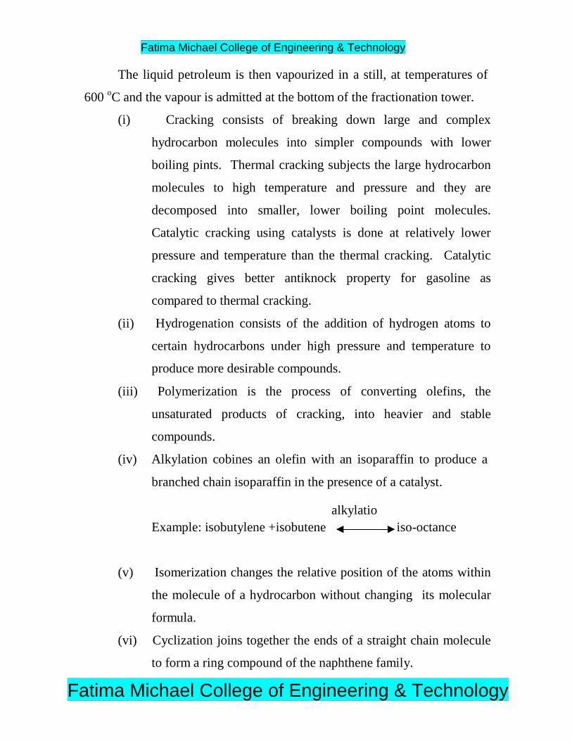
The liquid petroleum is then vapourized in a still, at temperatures of
600 oC and the vapour is admitted at the bottom of the fractionation tower.
(i) Cracking consists of breaking down large and complex
hydrocarbon molecules into simpler compounds with lower
boiling pints. Thermal cracking subjects the large hydrocarbon
molecules to high temperature and pressure and they are
decomposed into smaller, lower boiling point molecules.
Catalytic cracking using catalysts is done at relatively lower
pressure and temperature than the thermal cracking. Catalytic
cracking gives better antiknock property for gasoline as
compared to thermal cracking.
(ii) Hydrogenation consists of the addition of hydrogen atoms to
certain hydrocarbons under high pressure and temperature to
produce more desirable compounds.
(iii) Polymerization is the process of converting olefins, the
unsaturated products of cracking, into heavier and stable
compounds.
(iv) Alkylation cobines an olefin with an isoparaffin to produce a
branched chain isoparaffin in the presence of a catalyst.
alkylatioExample: isobutylene +isobutene iso-octance
(v) Isomerization changes the relative position of the atoms within
the molecule of a hydrocarbon without changing its molecular
formula.
(vi) Cyclization joins together the ends of a straight chain molecule
to form a ring compound of the naphthene family.
Fatima Michael College of Engineering & Technology
Fatima Michael College of Engineering & Technology
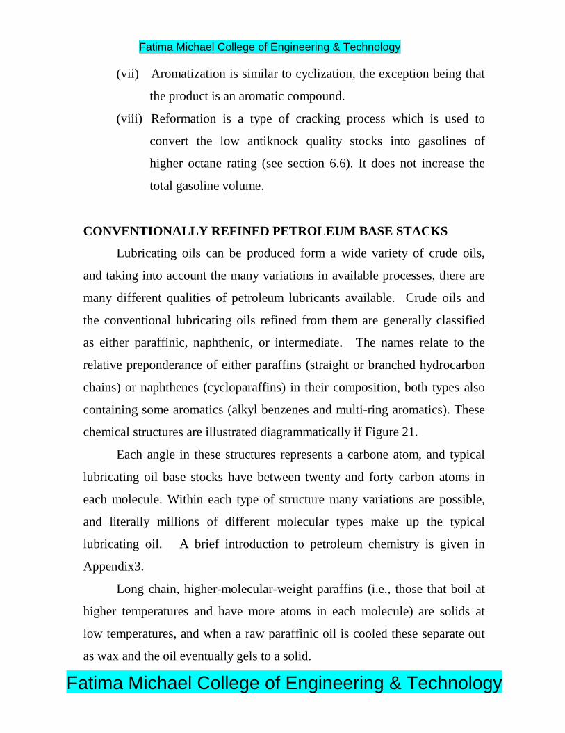
(vii) Aromatization is similar to cyclization, the exception being that
the product is an aromatic compound.
(viii) Reformation is a type of cracking process which is used to
convert the low antiknock quality stocks into gasolines of
higher octane rating (see section 6.6). It does not increase the
total gasoline volume.
CONVENTIONALLY REFINED PETROLEUM BASE STACKS
Lubricating oils can be produced form a wide variety of crude oils,
and taking into account the many variations in available processes, there are
many different qualities of petroleum lubricants available. Crude oils and
the conventional lubricating oils refined from them are generally classified
as either paraffinic, naphthenic, or intermediate. The names relate to the
relative preponderance of either paraffins (straight or branched hydrocarbon
chains) or naphthenes (cycloparaffins) in their composition, both types also
containing some aromatics (alkyl benzenes and multi-ring aromatics). These
chemical structures are illustrated diagrammatically if Figure 21.
Each angle in these structures represents a carbone atom, and typical
lubricating oil base stocks have between twenty and forty carbon atoms in
each molecule. Within each type of structure many variations are possible,
and literally millions of different molecular types make up the typical
lubricating oil. A brief introduction to petroleum chemistry is given in
Appendix3.
Long chain, higher-molecular-weight paraffins (i.e., those that boil at
higher temperatures and have more atoms in each molecule) are solids at
low temperatures, and when a raw paraffinic oil is cooled these separate out
as wax and the oil eventually gels to a solid.
Fatima Michael College of Engineering & Technology
Fatima Michael College of Engineering & Technology

FINISHING PROCESSES
The solvent extraction process does not remove all the reactive and
unstable material from the base stock, and without a finishing process the
oil would soon darken and precipitate sludge, especially when exposed to
light.
An early finishing process was clay treatment, whereby the oil was
mixed with “fuller’s earth,” which adsorbed reactive aromatic and unstable
molecules, and was then filtered off. The contaminated clay residues
presented a wasted disposal problem and there were also large product
losses. Hydro finishing is now the normal process, whereby the reffinate is
passed through a heated reactor packed with a catalyst (typically nickel and
molybdenum oxides on silica and alumina)and hydrogen is passed in under
pressure (Figure 25.). Hydrogenation reactions reactions covert the unstable
compounds into stable ones. Aromatics, for example, are converted into
naphthenes. Hydrofinishing does not substantially reduce the product yield,
it increases the V.I., and removes some of the sulfur compounds (which are
converted to hydrogen sulfide) and other trace materials. The extent of these
effects is very dependent on the processing conditions catalysts, temperature,
pressure, etc.
AUTOMOTIVE LUBRICANTS:
Many types of lubricants are used in a vehicle. engine oil and
transmission fluid, on a volume basis, provide a major portion of the
lubricants in a typical car or truck, and a great number of standard tests are
associated with these fluids. Greases provide a variety of highly specialized
functions and are found in many locations within a vehicle (for example, in
Fatima Michael College of Engineering & Technology
Fatima Michael College of Engineering & Technology

door locks, gears for seat adjustments and windshield wipers, bearings,
electrical contacts, and numerous other places).
In general, automotive lubricants consist of a base stock and various
additives. The choice of base stock depends on the function of the lubricant.
In the case of engine oil, various types of organic oils may be used:
paraffinic, naphthenic, and synthetic. Paraffinic hydrocarbons consist of
hydrogen and carbon atoms that are chemically bonded together in the form
of branched chains. Naphthenic hydrocarbons contain carbon atoms that are
bonded together in the form of rings. Paraffinic and naphthenic
hydrocarbons are typically derived by refining oil from oil wells. Synthetic
hydrocarbons are formed by combining small hydrocarbon building blocks
to form longer chains of a desired composition that tends to be more
resistant to chemiccd attack than is the case for oils produced by a refining
process.
Additives are blended into a base stock to provide desirable properties
such as optimum friction characteristics for the desired application, anti-
wear and antioxidant capability, defoaming capability, and corrosion
inhibition. The chemical nature of the additives for a given application are
chosen on the basis of their ability to perform their desired function,
withstand the conditions under which they must operate, and be compatible
with the base stock in which they are used.
Fatima Michael College of Engineering & Technology
Fatima Michael College of Engineering & Technology

TYPE OF FUELS
UNIT II – THEORY OF LUBRICATION
There are three types of fuels.
1. Liquid fuel 2. Gaseous fuel and 3. Solid fuel
General properties of fuels:
Fatima Michael College of Engineering & Technology
Fatima Michael College of Engineering & Technology

Fatima Michael College of Engineering & Technology
Fatima Michael College of Engineering & Technology
Fatima Michael College of Engineering & Technology
Fatima Michael College of Engineering & Technology
Fatima Michael College of Engineering & Technology
Fatima Michael College of Engineering & Technology
Fatima Michael College of Engineering & Technology
Fatima Michael College of Engineering & Technology

UNIT III – LUBRICANTS
COMBUSTION IN SPARK- IGNITION ENGINES:
In a conventional spark-ignition engine, the fuel and air are
homogeneously mixed together in the intake system, inducted through the
intake valve into the cylinder where it mixes with residual gases and is then
compressed. Under normal operating conditions, combustion is initiated
towards the end of the compression stroke at the spark plug by an electric
discharge.
STAGES OF COMBUSTION IN SI ENGINES:
A typical theoretical pressure-crank angle diagram, during the process
of compression (a-b) combustion (b-c) and expansion (c-d) in an ideal four-
stroke spark-ignition engine is shown in Fig.12.1. In an ideal engine, as can
be seen from the diagram, the entire pressure rise during combustion takes
place at constant volume i.e.., at TDC.
FLAME FRONT PROPAGAION:
For efficient combustion the rate of propagation of the flame front
within the cylinder is quite critical. The two important factors which
determine the rate of movement of the flame front across the combustion
chamber are the reaction rate and the transposition rate. The reaction rate is
the result of a purely chemical combination process in which the flame eats
its way into the unburned charge. The transposition rate is due to the
physical movement of the flame front relative to the cylinder wall and is also
the result of the pressure differential between the burning gases and the
unburnt gases in the combustion chamber.
Figure 12.3 shows the rate of flame propagation. In area I, (A-B), the flame
front progresses relatively slowly due to a low transposition rate and low
turbulence. The transposition of the flame front is very little since there is a
comparatively small mass of charge burned at the start. The low reactionFatima Michael College of Engineering & Technology
Fatima Michael College of Engineering & Technology

rate plays a dominant role resulting in a slow advance of the flame. Also,
since the spark plug is to be necessarily located in a quiescent layer of gas
that is close to the cylinder wall, the lack of turbulence reduces the reaction
rate and hence the flame speed. As the flame front leaves the quiescent zone
and proceeds into more turbulent areas (area II) where it consumes a greater
mass of mixture, it progresses more rapidly and at a constant rate (B-C) as
shown in Fig.12.3.
The volume of unburned charge is very much less towards the end of
flame travel and so the transposition rate again becomes negligible thereby
reducing the flame speed. The reaction rate is also reduced again since the
flame is entering a zone (area III) of relatively low turbulence (C-D) in Fig.,
12.3.
ABNORMAL COMBUSTION:
In normal combustion, the flame initiated by the spark travels across
the combustion chamber in a fairly uniform manner. Under certain
operation conditions the combustion deviates from its normal course leading
to loss of performance and possible damage to the engine. This type of
combustion may be termed as an abnormal combustion or knocking
combustion. The consequences of this abnormal combustion process are the
loss of power, recurring resignation and mechanical damage to the engine.
THE PHENOMENON OF KNOCK IN SI ENGINES:
In a spark-ignition engine combustion which is initiated between the
spark plug electrodes spreads across the combustible mixture. A definite
flame front which separates the fresh mixture from the products of
combustion travels from the spark plug to the other end of the combustion
chamber. Heat-release due to combustion increases the temperature and
consequently the pressure, of the burned part of the mixture above those of
Fatima Michael College of Engineering & Technology
Fatima Michael College of Engineering & Technology

the unburned mixture. In order to effect pressure equalization the burned
part of the mixture will expand, and compress the unburned mixture
adiabatically thereby increasing its pressure and temperature. This process
continues as the flame front advances through the mixture and the
temperature and pressure of the unburned mixture are increased further.
If the temperature of the unburnt mixture exceeds the self-ignition
temperature of the fuel and remains at or above this temperature during the
period of preflame reactions (ignition lag), spontaneous ignition or
autoignition occurs at various pin – point locations. This phenomenon is
called knocking. The process of autoignition leads towards engine knock.
EFFECT OF ENGINE VARIABLES ON KNOCK
From the discussion on knock in the previous section, it may be seen
that four major factors are involved in either producing or preventing knock.
These are the temperature, pressure, density of the unburned charge and the
time factors. Since, the effect of temperature, pressure and density are
closely interrelated, these three are consolidated into one group and the time
factors into another group.
OCTANE VALUE OF THE FUEL :
A higher self – ignition temperature of the fuel and low preflame
reactivity would reduce the tendency of knocking. In general , paraffin
series of hydrocarbon have the maximum and aromatic series the minimum
tendency to knock. The napthene series comes in between the two. Usually,
compounds with more compact molecular structure are less prone to known.
In aliphatic hydrocarbons, unsaturated compounds show lesser knocking
tendency that saturated hydrocarbons, the exception being ethylene,
acetylene and propylene.
COMBUSTION IN COMPRESSION – IGNITION ENGINES
Fatima Michael College of Engineering & Technology
Fatima Michael College of Engineering & Technology

There are certain basic differences existing between the combustion
process in the SI and CI engines. In the SI engine, a homogeneous
carbureted mixture of gasoline vapour and air, in a certain proportion is
compressed (compression ratio 6:1 to 10:1) and the mixture means of an
electric spark. A single flame front progresses through the air – fuel mixture
after ignition.
In the CI engine, only air is compressed through a high compression
ratio (16:1 to 20:1) raising its temperature and pressure to a high value. Fuel
is injected through one or more jets into the highly compressed air in the
combustion chamber. Here the fuel jet dis integrates into a core a fuel
surrounded by a spray envelope of air and fuel particles. This spray envelop
is created both by the atomization and vaporization of the fuel. The
turbulence of the air in the combustion chamber passing across the jet tears
the fuel particles from the core. A mixture of air and fuel forms at some
location in the spray envelope and oxidation starts.
The liquid fuel dropiets evaporate by absorving the vaporization from
the surrounding air which reduces the temperature of a tine layer of air
surrounding the droplet and some time elapses before this temperature can
be raised again by absorbing heat from the bulk of air. As soon as this
vapour and air reach the level of the autoignition temperature and if the local
A/F ratio is within the combustible range, ignition takes place. Thus it is
obvious that at first there is a certain delay period before ignition takes
place.
Since the fuel droplets cannot be injected and distributed uniformly
throughout the combustion space, the fuel air mixture is essentially
heterogeneous. If the air within the cylinder were motionless under these
Fatima Michael College of Engineering & Technology
Fatima Michael College of Engineering & Technology
conditions, there will not be enough oxygen in the burning zone and burning
of the fuel would be eighter flow or totally fail as it would be s9urrgounded
by its own precuts of combustion. Hence an orderly and controlled
movement must be imparted to the air and the fuel so that a continuous flow
of fresh air is brought to each burning droplet and the products of
combustion are swept away. This air motion is called the air swirl and its
effects.
STAGES OF COMBUSTION IN CI ENGINES
The combustion in a CI engine is considered to be taking place in four
stages. It is divided into the ignition delay period, the period of rapid
combustion, the period of controlled combustion and the period of after
burning. The details are explained below.
IGNITION DELAY PERIOD
The ignition delay period is also called the preparatory phase during
which some fuel has already been admitted but has not vet ignited. This
period is counted from the state of injection to the point where the pressure
time curve separates from the motoring curve indicated as start of
combustion.
PERIOD OF RAPID COMBUSTION
The period of rapid combustion also called the uncontrolled
combustion, is that phase in which the pressure rise is rapid. During the
delay period that droplets have had time to spread over a wide area and fresh
air is always available around the droplets. Most of the fuel admitted would
have evaporated and formed a combustible mixture with air.
PERIOD OF CONTROLLED COMBUSTION
The rapid combustion period is followed by the third stage, the
controlled combustion. The temperature and pressure in the second stage is
Fatima Michael College of Engineering & Technology
Fatima Michael College of Engineering & Technology
already quite high. Hence the fuel droplets injected during the second stage
burn faster with reduced ignition delay as soon as they find the necessary
oxygen and any further pressure rise is controlled by the injection rate.
PERIOD OF AFTER BURNING
Combustion does not cease with the completion of the injection
process. The unburnt and partially burnt fuel particles left in the combustion
chamber start burning as soon as they come into contract with the oxygen.
This process continues for a certain duration called the after burning period.
Usually this period starts from the point of maximum cycle temperature and
continues over a part of the expansion stroke. Rate of after burning depends
on the velocity of diffusion and turbulent mixing of unburnt and partially
burnt fuel with the air. The duration of the after burning phase may
correspond to 70-80 degrees of crank travel from TDC.
FACTORSA AFFECTING THE DELAY PERIOD
Many design and operating factors affect the delay period. The
important ones are :
i) Compression ratio
ii) Engine speed
iii)Output
iv) Automization of fuel and duration of injection
v) Injection timing
vi) Quality of the fuel
vii) Intake temperature
THE PHENOMENON OF KNOCK IN CI ENGINES
In CI engines the injection process takes place over a definite interval
of time. Consequently, as the first few droplets to be injected are passing
Fatima Michael College of Engineering & Technology
Fatima Michael College of Engineering & Technology

through the ignition delay period, additional droplets are being injected into
the chamber. If the ignition delay of the fuel being injected is short, the
first few droplets will commence the actual burning phase in a relatively
short time after injection and a relatively small amount of fuel will be
accumulated in the chamber when actual burning commences.
Effect of Variables on the Delay Period
Increases in variable Effect on Delay
Period
Reason
Cetane number of fuel Reduces Reduces the self-ignition temperature
Injection pressure Reduces Reduces physical delay due to greater
surface volume ration
Injection timing advance Reduces Reduced pressures and temperatures when
the injection begins
Compression ration Reduces Increases air temperature and pressure and
reduces autoignition temperature
Intake temperature Reduces Increases air temperature
Jacket water temperature Reduces Increases wall and hence air temperature
Fuel temperature Reduces Increases chemical reaction due to better
vaporization
Intake pressure
(Supercharging)
Reduces Increases density and also reduces
autoignition temperature
Speed Increases in terms of
crank angle. Reduce
in terms of
milliseconds
Reduces loss of heat
Load (Fuel air ratio) Decreases Increase the operating temperature
Engine size Decrease in terms of
crank angle. Little
effect in terms of
Larger engines operator normally at low
speeds
Fatima Michael College of Engineering & Technology
Fatima Michael College of Engineering & Technology

milliseconds
Type of combustion
chamber
Lower for engines
with precombustion
Due to compactness of the chamber.
COMPARISON OF KNOCK IN SI AND CI ENGINES
It may be interesting to note that knocking in spark – Ignition engines
and compression – ignition engines is fundamentally due to the autoignition
of the fuel air mixture. In both the cases, the knocking depends on the
autoignition lag of the fuel air mixture. But caseful examination of the
knocking phenomenon in spark – ignition and the compression – ignition
engines reveals the following differences. A comparison of the knocking
process in SI and CI engines .
i) In spark – ignition engines, the autoignition of the end gas away from the
spark plug most likely near the end of the combustion causes knocking.
But in compression ignition engines the autoignition of the charge
causing knocking is at the start of combustion.
ii) In spark ignition engine, the charge that autoignites is homogeneous and
therefore intensity of knocking or the rate of pressure rise at explosive
autoignition is likely to be more than that in compression – ignition
engines where the fuel and air are not homogeneously mixed even when
explosive autoignition of the charge occurs. There fore, it is often called
detonation is SI engines.
iii) In compression – ignition engines, only air is compressed during the
compression stroke and the ignition can take place only after fuel is
injected just before the top dead centre. Thus there can be a no
preignition in compression – ignition engines as in spark – ignition
engines.
Fatima Michael College of Engineering & Technology
Fatima Michael College of Engineering & Technology

CHARACTERISTICS TENDING TO REDUCE DETONATION OR
KNOCK
S.No Characteristics SI Engines CI Engines
1. Ignition temperature of fuel High Low
2. Ignition delay Long Short
3. Compression ratio Low High
4. Inlet temperature Low High
5. Inlet pressure Low High
6. Combustion wall temperature Low High
7. Speed, rpm High Low
8. Cylinder size Small Large
COMBUSTION CHAMBERS FOR CI ENGINES
The most important function of the CI engine combustion chamber is
to provide proper mixing of fuel and air in a short time. In order to achieve
this an organized air movement called the air swirl is provided to produce
high relative velocity between the fuel droplets.
ADDITIVES
Some compounds called additives or dopes are used to improve
combustion performance of fuels. The main combustion problems that arise
when operating conditions become severe or unfavorable are knock and
surface ignition.
REQUIREMENTS OF AN ADDITIVE:
For an additive to be acceptable it must satisfy certain basic
requirements, which are as follows:
Fatima Michael College of Engineering & Technology
Fatima Michael College of Engineering & Technology

i) It must be effective in desired reaction, i.e., knock-resistant or surface
ignition resistant or both.
ii) It should be soluble in fuel under all conditions.
iii) It should be stable in storage and have no adverse effect on fuel
stability.
iv) I should be in the liquid phase at normal temperature, and volatile to
give rapid vaporization in manifold.
v) I must not produce harmful deposits.
vi) Its water solubility must be minimum to minimize handling losses.
The effectiveness of antiknock additives is measured by the increase
in antiknock quality of the treated fuel, that is the increase in octane number.
The mechanism by which additives decrease the tendency of the fuel to auto
ignite is by no means very clear till now. The antiknock tendency of
additives is believed to be the result of breaking of chain reactions thereby
delaying the auto ignition of the end mixture and permitting the normal
flame to pass through it without combustion knock.
Tetraethyl Lead. The principal antiknock agent is tetraethyl lead (TEL)
(C2H5)4P6. TEL is a heavy liquid weighing about 1.7 kg per litre. It boils
at 200C and is soluble in gasoline. It was discovered in 1922 by Midgley
and Boyd of General motors corporation of U.S.A. The average gasoline
blends have octane number in the range 75 to 85 which is increased to 90 to
95 by addition of TEL
The addition of TEL does not change the reactions forming aldehydes
and ketones. It does not affect the rate of energy liberation during a
precombustion period.
TETRA METHYL LEAD :
Fatima Michael College of Engineering & Technology
Fatima Michael College of Engineering & Technology
The problem of maldistribution can be countered if boiling point of
lead carrier can be decreased. So instead of TEL these days, tetra – methyl
lead (TML), (CH3)4 Pb is sometimes used. Since TML boils at 110C that is
within the medium fraction range, knock protection is provided, and
improvements have been noted up to 6 road octane number than those
obtained with TEL.
UNIT IV -
INTRODUCTION:
PROPERTIES AND TESTING OF FUELS
Fatima Michael College of Engineering & Technology
Fatima Michael College of Engineering & Technology

Engine friction if defined as the difference between the indicated
horse-power (power at piston top as produced by the combustion gases) and
the brake horse-power (useful power) available at the output shaft, i.e.
f.p.=i.p.-b.p
TOTAL ENGINE FRICTION
Total engine friction, defined as the difference between ihp and bhp,
includes the power required to drive the compressor or a scavenging pump
and the power required drive engine auxiliaries such as oil pump, coolant
pump and fan, etc.
If the power to drive the compressor and auxiliaries is neglected, the
total engine friction can be divided into five main components. These are:
1. Crankcase mechanical friction.
2. Blowby losses (compression-expansion pumping loss).
3. Exhaust and inlet system throttling losses.
4. Combustion chamber pumping loop losses.
5. Pistion mechanical friction.
Crankcase Mechanical Friction. Crankase mechanical friction can further be
sub-divided into:
(1)Bering friction,
(2)Valve gear friction, and
(3)Pump and miscellanceous friction.
Blowby Losses:Blowby is the
phenomenon of leakage of combustion
products past the piston and piton rings
from the cylinder to the crankcase.
Exhaust and Inlet Throttling Loss:
The standard practice for sizing the exhaust valve is to make them a
certain percentage smaller than the inlet valves.
Pistion Mechanical Friction:
Fatima Michael College of Engineering & Technology
Fatima Michael College of Engineering & Technology

Piston mechanical friction can be sub-divided into:
1. Viscous friction
2. Non-viscous friction
a) Friction due to ring tension
b) Friction due to gas pressure forces behind the ring.
EFFECT OF ENGINE VARIABLES ON ENGINE FRICTION ‘
Effect of stroke/bore ration:
The effect of stroke/bore ration on engine friction and economy is
very small.
Effect of cylinder size and number of cylinders:
The friction and economy improves as a smaller number of larger
cylinders are used. This is because the proportion between the working
pistio area and its friction producing area, i.e. circumference, is reduced.
Effect of number of piston rings:
Fig.14.11 Shows the effect of pistion rings on total piston ring
friction. Comparing with Fig. 14.9 it can be said that the effect of number of
pistion ring is not very critical and this number is usually chosen on the basis
of cost, size and other requirements rather than on the basis of their effect on
friction.
Effect of compression ration:
Fatima Michael College of Engineering & Technology
Fatima Michael College of Engineering & Technology
As already discussed the friction mean effective pressure increases as
the compression ratio is increased. But the mechanical efficiency either
remains constant or improvers as the compression ratio is increased.
Effect of engine speed:
As already discussed engine friction increases rapidly as the speed
increases. The best way to improve mechanical efficiency as the speed
increases the number of cylinders.
Motering Method:
In the motoring method, engine is driven with the help of an external
motor. The power consumed by this motor, if corrected for mechanical and
other losses of the motor, gives the fp of the engine.
LUBRICATION
LUBRICATION PRINCIPLES:
Consider a block resting on a flat surface covered with a layer of
lubricating oil. If the weight of the block is very high or the oil is thin, the
oil will squeeze out. In other words, a thick oil can support a higher load
than that supported by a thin oil.
Hydrodynamic lubrication:
When this block is moved over the surface, a wedge-shaped oil film is
built up between the moving block and the surface. This wedge-shaped film
is thicker at the leading edge than at the rear.
This type of lubrication where a wedge-shaped oil film is formed
between two moving surfaces is called hydrodynamic lubrication.
Elastohydrodynamic lubrication:
When the load acting on the bearings is very high, the material itself
deforms elastically against the pressure built up of the oil film. This type of
lubrication, called elastohydrodynamic lubrication, occurs between cams and
Fatima Michael College of Engineering & Technology
Fatima Michael College of Engineering & Technology

followers, gear teeth, and rolling bearings where the contact pressures are
extremely high.
Boundary lubrication:
If the film thickness between the two surfaces in relative motion
becomes so thin that formation of hydrodynamic oil film is not possible and
the surface high spots or asperities penetrate called boundary lubrication.
Such a situation may arise due to too high a load, too thin an oil or
insufficient supply of oil due to low speed of movement. Most of the wear
associated with firction occurs during boundary lubrication due to metal-to-
metal contact. A condition of boundary lubrication always exists when the
engine is first started. The shaft is in contact with the bottom of the bearing
with only a thin surface film of oil formed on them. The bearing surfaces
are not perfectly smooth-they have ‘hills’ and ‘valleys’ which tear this thin
film which is constantly formed while the crankshaft is turning slowly. As
the speed increases it switches on to hydrodynamic lubrication. Boundary
lubrication may also occur when the engine is under very high loads or when
the oil supply to the bearing is insufficient.
Bearing Lubrication:
Show the action of the lubricant in a bearing. When the shaft is not
rotating, there is metal-to-metal contact the shaft and bearing due to
squeezing out of oil from under the journal because of shaft weight. As the
shaft starts to rotate, due to high starting friction, the journal momentarily
rolls slightly up the side wall. If some surface oil remains on the bearing the
shaft will slide back to the bearing bottom when it hits the oil. This
climbing and sliding back continues till sufficient oil is supplied by the
pump so that the climbing shaft grabs the oil instead of the bearing wall and
a curved wedge-shaped oil film is formed. This film now supports the shaft
Fatima Michael College of Engineering & Technology
Fatima Michael College of Engineering & Technology

in the bearing. The only friction encountered is the small fluid friction
caused by the rapid shear of the oil particles as they slip over one anther.
This phenomenon of shift from boundary lubrication to
hydrodynamics lubrication is shown in Fig. 14.17 with the help of the
relation between coefficient of friction µ and a dimensionless number ZN /P
where Z is the oil viscosity, P is the pressure and N is the Speed. The
coefficient of friction µ is minimum only at one value of ZN / P. To the left
of this pint the hydrodynamic pressure developed by the film is too low to
lift the shaft and metal-to metal contact ensues. This is the zone of boundary
lubrication. Reduction in viscosity or speed of increae in load (P), all move
the operating point to left. The operation in this zone is unstable because
under boundary lubrication the coefficient of friction is high which results in
more heat generation. This further decreases the viscosity of the oil which,
in turn leads to higher value of coefficient of friction through lower values of
ZN / P. This ultimately leads to seizure of metallic surfaces.
Viscosity:
Viscosity of an oil is measure of its reistance to flow and is usually
measured in terms of Saybolt Universal Seconds (SUS) which is the time
required, in seconds, for a given quantity of the oil to flow through a
capillary tube under specified test conditions. Viscosity is usually expressed
a two temperatures-18oC (0oF) and 99oC (210oF).
Viscosity Index:
The viscosity of an oil is substantially affected by its temperature,
higher the temperature lower is the viscosity. This variation of viscosity of
an oil with changes in temperature is measured by its Viscosity Index (V.I.)
The oil is compared with two reference oils having same viscosity at 99oC
(210oF).
Fatima Michael College of Engineering & Technology
Fatima Michael College of Engineering & Technology
Cloud Point and Pour Point: If an oil is cooled, it will start solidifying at
some temperature. This temperature is called cloud point.
The pour pint is that temperature just above which the oil sample will
not flow under certain prescribed conditions.
Flash Point:
The temperature at which the vapours of an oil flash when subject to a
naked flame is known as the flash point of the oil. If the container is closed
at the time of the test it is called closed flash point, and if open it is called
open flash point. Fire point is the temperature at which the oil, if once lit
with flame, will burn steadily at least for 5 seconds. This is usually 11oC
higher than open flash point and varies from 190oC to 290oC for the
lubricants used for the internal combustion engines.
Carbon Residue: Carbon residue is the quantity of the known mass sample
of the oil, which on evaporation under specific conditions remains as
carboneous residue.
Oiliness: The property of an oil to cling to the metal surfaces by
molecular action and then to provide a very thin layer of lubricant under
boundary lubrication conditions is called the oiliness or lubricity or film
strength.
Colour: This has no practical significance except that it is an indication
of the degree of refining of the oil.
Fatima Michael College of Engineering & Technology
Fatima Michael College of Engineering & Technology
UNIT V – COMBUSTION AND FUEL RATING
Introduction:Lubrication circuit is one of the most important ones in the engine.
The engine cannot run smoothly for more than a few minutes without thelubricating oil.
Requirements of Lubricants
1. ViscosityIn simple language, the viscosity may be considered as the
resistance of the lubricating oil to flow.
2. Physical StabilityThe lubricating oil must be stable physically at the lowest and the
highest temperatures encountered in practice.
3. Chemical StabilityAt higher temperatures the oil should remain chemically stable. Thereshould not be any tendency for oxide formation; many of the oxidationproducts being sticky substances clog the lines and cause faulty piston ringand valve action
4. Resistance Against CorrosionThe oil should not have any tendency to corrode the pipe lines, crank
case and other engine parts with which it comes into contact.
5. Pour PointThe minimum temperature at which the oil will pour is called its pour
point.
6. Flash PointThe flash point of the oil should be sufficiently high so as to avoid flashingof oil vapors at the temperatures occurring in common use.
7. CleanlinessThe oil should be sufficiently clean
Fatima Michael College of Engineering & Technology
Fatima Michael College of Engineering & Technology

TYPES OF LUBRICANTS
1. Animal Oils
2. Vegetable Oils
3. Mineral Oils
4. Synthetic Lubricants
The examples of synthetic lubricants are silicon fluids, polyglycol ethers andaliphatic diester oil. In general, they have superior property than the mineraloil but the high cost limits their use.
5. Greases
They are suspension of metallic soaps dispersed in lubricating oil. Greasesfind use in automobile at places where retention of liquid lubricants isdifficult and the high temperature is encountered.
TESTING OF LUBRICANTS
Physical tests1. Viscosity test2. Flash point and fire point test3. Loss due to evaporation4. Cold or pour point test5. Specific gravity test
Chemical Tests1. Acid value test2. Sponification value test3. Insoluble residue test4. Moisture and emulsification test
Viscosity Tests1. Redwood viscometer2. Saybolt viscometer3. Engler viscometer
Fatima Michael College of Engineering & Technology
Fatima Michael College of Engineering & Technology

OIL ADDITIVES
1. Oxidation Inhibitors
These inhibit formation of varnish by preventing the oxidation of the oil atthe engine operating condition
2. Corrosion Inhibitors
These prevents are at least reduce the formation of acids which wouldcause baring corrosion .These consists of oxidation inhibitors with theaddition of metal salt of thiophosphoric acid and sulphurized waves.
3. Detergents
These are also called dispersant additives. This inhibits the formation of lowtemperature sludge binders and breaks the sludge particles into finelydivided particles, which stay in the oil in fine suspension and are removedwhen the engine oil changed.
4. Viscosity Index Improvers
These are the additive which do not allow or at least minimize the decreaseof oil viscosity with the increase in temperature.
5. Anti foaming additives
Anti foaming additives are available which suppress the foaming tendencyof the oil. Polyorganosiloxanes are the most common anti foaming additives
6. Extreme pressure Additives
These cater for more difficult condition of lubrication .e.g. the one arisingbetween the highly stressed cams and valve tappets. These prevents metal to
Fatima Michael College of Engineering & Technology
Fatima Michael College of Engineering & Technology

metal by forming a chemical film. The polymeric materials such aspolyisobutane form such additives.
7. Pour Point depressantsThese are to lower the pour point of the oil by coating wax crystals
in the oil so that they would not stick together and thus facilitate oil flow.
8. OthersApart from above a large variety of additives are available some of these
are rust inhibitors, water repellents, emulsifiers, dyes, odour controllers.
EFFECTS OF ENGINE CONDITIONS OF LUBRICATING OIL
1. Sludge Formation2. Lacquer formation3. Oil dilution4. Carbon deposition
CONSUMPTION OF LUBRICATING OIL
1. Combustion2. Loss through Leakage3. Loss through crankcase ventilation4. Loss on account of wear of engine parts
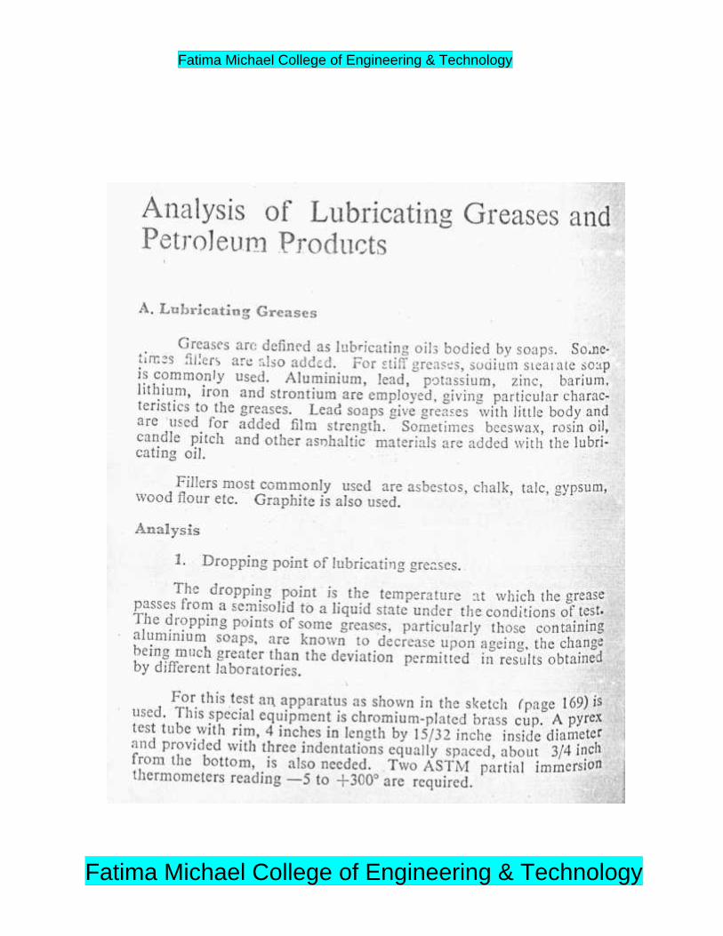
GREASES
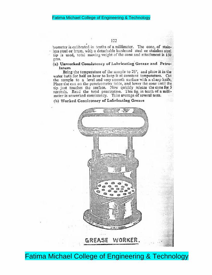
Greases are prepared by saponification of fat followed by adding hotlubricating oil under agitation .The total amount of mineral oil addeddetermine the consistency of thefinished greases.
Greases have higher shear or frictional resistance than oil and, therefore cansupport much heavier loads at lower speeds. They also do not require asmuch attention unlike the lubricating liquids. But greases have tendency toseparate into oil and soap.
Fatima Michael College of Engineering & Technology
Fatima Michael College of Engineering & Technology

1.Calcium based greases are emulsion of petroleum oil with calcium soap,they are generally ,prepared by adding requisite amount of calciumhydroxide to a hot oil, like allow while under agitation .These greases arecheapest and most commonly used .They are insoluble in water, so waterresistant. However they are satisfactory for use at low temperature, becauseabove 80 degree Celsius, oil and soap begins to separate out.
2. Soda based greases are petroleum oil, thickened by mixing sodium soap,they are not water resistant, because the sodium soap content is soluble inwater .However they can be used up to 175 degree celcius.They are suitablefor use in ball bearing, where the lubricants gets heated due to friction.3. Lithium based greases are petroleum oils are thickened by mixing lithiumsoap. They are water resistant and suitable for use at lower temperature (upto 15 degree Celsius) only.
4. Axle greases are very cheap resin greases prepared by lime to resin andfatty oil. The mixture is thoroughly mixed and allowed to stand, when greasefloats are stiff mass. Fillers like talc and mica are also added to them. Theyare water resistant and suitable for less delicate equipments working underhigh loads and at low speeds.
Fatima Michael College of Engineering & Technology
Fatima Michael College of Engineering & Technology
Fatima Michael College of Engineering & Technology
Fatima Michael College of Engineering & Technology

Fatima Michael College of Engineering & Technology
Fatima Michael College of Engineering & Technology
Fatima Michael College of Engineering & Technology
Fatima Michael College of Engineering & Technology

Fatima Michael College of Engineering & Technology
Fatima Michael College of Engineering & Technology

Fatima Michael College of Engineering & Technology
Fatima Michael College of Engineering & Technology
Fatima Michael College of Engineering & Technology
Fatima Michael College of Engineering & Technology

Fatima Michael College of Engineering & Technology
Fatima Michael College of Engineering & Technology
Fatima Michael College of Engineering & Technology
Fatima Michael College of Engineering & Technology

Fatima Michael College of Engineering & Technology
Fatima Michael College of Engineering & Technology

Fatima Michael College of Engineering & Technology
Fatima Michael College of Engineering & Technology

Fatima Michael College of Engineering & Technology
Fatima Michael College of Engineering & Technology
Fatima Michael College of Engineering & Technology
Fatima Michael College of Engineering & Technology
Fatima Michael College of Engineering & Technology
Fatima Michael College of Engineering & Technology
Fatima Michael College of Engineering & Technology
Fatima Michael College of Engineering & Technology
Fatima Michael College of Engineering & Technology
Fatima Michael College of Engineering & Technology

Fatima Michael College of Engineering & Technology
Fatima Michael College of Engineering & Technology

Fatima Michael College of Engineering & Technology
Fatima Michael College of Engineering & Technology

Fatima Michael College of Engineering & Technology
Fatima Michael College of Engineering & Technology