Embed Size (px)
Citation preview
Available online at www.sciencedirect.com
Procedia Engineering 00 (2009) 000–000
ProcediaEngineering
www.elsevier.com/locate/procedia
Fatigue 2010
Fatigue strength and failure mechanism for the aluminium wrought alloy EN AW 6056 in the VHCF-region and influence of notches
and compressive residual stresses
Daniela Schwerdta*, Brita Pyttela, Christina Bergera
aInstitute for Materials Technology and State Materials Testing Institute, Technische Universität Darmstadt, Grafenstr. 2, 64283 Darmstadt, Germany
Received 3 March 2010; revised 9 March 2010; accepted 15 March 2010
Abstract
The fatigue strength and the transition of failure mechanism from the high cycle fatigue (HCF) to the very high cycle fatigue regime (VHCF) for EN AW 6056 were investigated at mechanically polished, smooth specimens. Fatigue tests were conducted with a servohydraulic testing machine and a resonant frequency machine at room temperature. Tests run up to a maximum number of cycles N = 2·108.The results reveal that the fatigue strength decreases with increasing number of cycles, which is known for materials with face-centred cubic lattice. In the very high cycle regime the crack initiation sites of the smooth specimens were internal. Fracturesurface and microstructure of the crack initiation sites were investigated by means of scanning electron microscope (SEM), energy dispersive X-ray analysis (EDX), electron back scatter diffraction analysis (EBSD) and metallographic methods. The influence of notches was investigated at slightly notched (Kt = 1.75) and sharp notched (screws M10, Kt = 4.7) specimens. The influence of compressive residual stresses was investigated by a comparison of precision-turned and shot-peened, slightly notched specimens as well as screws of with thread rolling before heat treatment and thread rolling after heat treatment. The fatigue strength of the specimens without compressive residual stresses decreases with increasing number of cycles. The fatiguestrength of the specimens with compressive residual stresses shows a horizontal SN-curve after a point of deflection. The crackinitiation sites of the notched specimens were always at the root of the notch independent of the compressive residual stresses and the number of cycles.
Keywords: Fatigue strength behaviour, smooth and notched specimens, residual stresses, wrought aluminum alloy, aluminum screws
1. Introduction
It is a matter of fact that the fatigue strength of materials with face-centered cubic lattice, as for instance aluminium, decreases more or less with increasing fatigue life. An endurance limit as a lower bound could not be found yet. It is generally well known, not only for aluminium, that crack initiation at lower number of cycles
* Corresponding author. Tel.: +49 6151 16 5351; fax: +49 6151 16 6118. E-mail address: [email protected].
c© 2010 Published by Elsevier Ltd.
Procedia Engineering 2 (2010) 1505–1514
www.elsevier.com/locate/procedia
1877-7058 c© 2010 Published by Elsevier Ltd.doi:10.1016/j.proeng.2010.03.162
Open access under CC BY-NC-ND license.
Open access under CC BY-NC-ND license.

2 Schwerdt et al./ Procedia Engineering 00 (2010) 000–000
N < 107 usually occurs at the surface, whereas after a much larger number of cycles in the VHCF-regime fatigue cracks initiate internally. Two different initiation sites for two different groups of material may occur. For high-strength steels, cast iron and cast aluminium the internal crack initiation is related to defects (inclusion, pores). For titanium alloys, austenitic steels and low carbon steels crack initiation is not related to defects. The fracture mechanisms are more influenced by microstructure, interface and microplasticity [1].
Investigations were done on the wrought aluminium alloy EN AW 6056 with only small intermetallic particles to determine fatigue strength and failure mechanism at number of cycles up to N = 2•108. The influence of notches was investigated at slightly notched (Kt = 1.75) and sharp notched (screws M10, Kt = 4.7 [4]) specimens. The influence of compressive residual stresses was investigated by a comparison of precision-turned and shot-peened, slightly notched specimens as well as of screws with thread rolling before heat treatment and thread rolling after heat treatment. The present guideline for the calculation of bolted joints [2] applies to steel screws with thread rolling before or after heat treatment, not for aluminium screws. It assumes that an endurance limit exists after a point of deflection at N = 2•106 [2]. Screws are normally tested up to N = 5•106 or 107 number of cycles only.
2. Material
All specimens (smooth, slightly notched and sharp notched (two series of screws M10)) were made from the same heat of the aluminium wrought alloy EN AW 6056. Table 1 shows the chemical composition. This alloy can be maximum precipitation-hardened over metastabile phase Mg2Si. The mechanical properties of the smooth specimens, the screw material and the screws with the two series thread rolling before or after heat treatment are presented in Table 2. The cyclic stress-strain behaviour of EN AW 6056 was measured with incremental step test. The material does not show a cyclic hardening or softening.
The smooth (Kt=1) and the slightly notched (Kt=1.75) specimens are made of EN AW 6056 – T6 (maximum precipitation-hardened), Fig.1 shows the microstructure. The incoherent intermetallic particles, Fig. 1c, are Mg2Si(dark grey) and Al6Mn, Al6Fe (light grey) which result from the melting process. They do not increase strength like coherent and semi-coherent particles which cannot be shown by light microscopy. The average grain-diameter of EN AW 6056 is about ca. 100 μm. They are elongated in direction of pull (longitudinal). The residual stresses were measured exemplarily at one unstressed and mechanical polished specimen (Kt = 1) of EN AW 6056 by X-ray diffractometry. Compressive residual stresses at the surface of 177 MPa were detected. Probably they were inserted by precision-turning. This value equates to the half of the yield strength.
The screws are manufactured from the same semi-finished product (bar stock with diameter of 18 mm) as the smooth and the slightly notched specimens, but afterwards they meet another heat treatment and forming process. The first series of screws are thread rolled before heat treatment (tbh) and the second series are thread rolled after heat treatment (tah). Therefore the two series of screws are different in microstructure, compressive residual stress and also in mechanical properties and also differ from the maximum precipitation-hardened material. The microstructures of the two series of screws are shown in Fig. 2 and 3. During the heat treatment of thread rolled screws the area with high plastic deformation, due to thread rolling process, recrystallises to fine globular grains, Fig. 2 b. As a result of this a somewhat higher strength exists in the groove of the thread compared to the matrix material. At the screws with thread rolling after heat treatment the groove of the thread shows also a higher strength than the matrix resulting from the extremely deformated grains in the groove (strain-hardening). But the essential is that additionally compressive residual stresses are generated in the groove of the thread [2, 3].
Table 1: Chemical composition wt %) of EN AW 6056
Si Fe Cu Mn Mg
EN AW 6056 (AlMg1SiCu) 1.01 0.182 0.574 0.547 0.864
1506 D. Schwerdt et al. / Procedia Engineering 2 (2010) 1505–1514
Schwerdt et al./ Procedia Engineering 00 (2010) 000–000 3
Table 2: Mechanical properties of EN AW 6056, T6-maximum precipitation-hardened, material of screws and screws for the two series tbh - thread rolling before heat treatment and tah - thread rolling after heat treatment, * - calculated with stress cross section of the bolt thread according to [2]
Rp0.2 [MPa] Rm [MPa] A [%] Z [%] HV0.3
EN AW 6056-T6 344 393 19 47 131
Material of screw tbh 367 412 14 40 137
Screw tbh - 396* - - -
Material of screw tah 362 412 18 51 132
Screw tah - 410* - - -
ba c
Fig. 1. Microstructure of EN AW 6056 maximum precipitation-hardened, (a) unetched, incoherent, intermetallic particles (b) etched, grain structure longitudinal, (c) grain structure transversal
ba cFig. 2. Microstructure of screw M10 of EN AW-6056 longitudinal, thread rolling before heat treatment, (a) unetched, overview of the thread, (b) etched, grain structure in a groove of a thread with fine globular grains in the zone with high plastic deformation from the thread rolling process, (c) etched, grain structure in the matrix
b caFig. 3. Microstructure of screw M10 of EN AW-6056 longitudinal, thread rolled after heat treatment, (a) unetched, overview of the thread, (b) etched, grain structure in a groove of a thread with extremely deformated (elongated) grains in the groove, (c) etched, grain structure in the matrix
D. Schwerdt et al. / Procedia Engineering 2 (2010) 1505–1514 1507
4 Schwerdt et al./ Procedia Engineering 00 (2010) 000–000
3. Specimens and experimental procedure
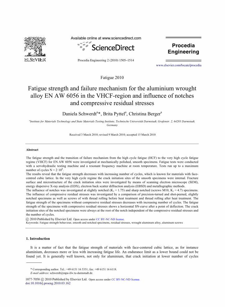
Fatigue tests were conducted in air at room temperature under load control with a servohydraulic testing machine (VHF 50 D from Instron Schenck) and a frequency of 400 Hz at R = 0.1 with
smooth specimens, mechanical polished, diameter d = 6 mm, made of EN AW 6056 maximum precipitation-hardened and slightly notched (Kt = 1.75) specimens (precision-turned), diameter d = 6 mm, made of EN AW 6056 maximum precipitation-hardened.Fatigue tests with screws M 10 with thread rolling before heat treatment and thread rolling after heat treatment made of EN AW 6056 in combination with steel nuts (Kt = 4.7 [4]) were conducted with a frequency of 150 Hz
under load control with a high frequency pulsator at R = 0.1. The R-ratio of 0.1 is untypical for screws but was chosen for comparison with the results from smooth and
slightly notched (Kt = 1.75) specimens. Fig. 4 shows the geometry of the smooth (a), the slightly notched (b) and the sharp notched (screw M10) specimens.
For determining a S-N line for number of cycles N < 106 a linear regression was carried out with k
nknakNN / (1). There are k slope, a nominal stress amplitude, Nk stress amplitude and Nk number of cycles at point of
deflection. For number of cycles beyond Nk it is difficult to get an analysing method which considers the specimens with failure and also the specimens without failure and calculates a S-N line with a decrease (slope k*) of fatigue strength. Therefore and because the fit was the best in comparison to other tested analysing- methods, the slope k* = 22 and the scatter for stress
25,1:1%90/%10:1 sasa PPT (2) were taken from a recommendation in [5]. There Ps is the probability of survival. The FKM- guideline
“Analytical strength assessment of components” [6] allows to estimate fatigue strength of components for probability of survival PS = 97.5 %. After [6] the slope of the S-N curve for number of cycles N < 106 is k = 5, for 106 < N < 2·108 k = 15. For N > 2·108 the guideline [6] assumes a fatigue limit. The fatigue strength which was estimated with [6] is also plotted in the diagrams to compare it with the experimental results.
The fracture surface of all smooth and notched specimens and some surfaces of smooth specimens were investigated with scanning electron microscope (SEM). The back scatter diffraction analysis (EBSD) was used to identify a fracture mechanism of EN AW 6056.
a b
c
Fig. 4. Geometry of (a) smooth, (b) notched and (c) sharp notched (screw M10) specimen
1508 D. Schwerdt et al. / Procedia Engineering 2 (2010) 1505–1514
Schwerdt et al./ Procedia Engineering 00 (2010) 000–000 5
4. Results and Discussion
4.1 Fatigue strength and failure mechanism of EN AW-6056 maximum precipitation-hardened
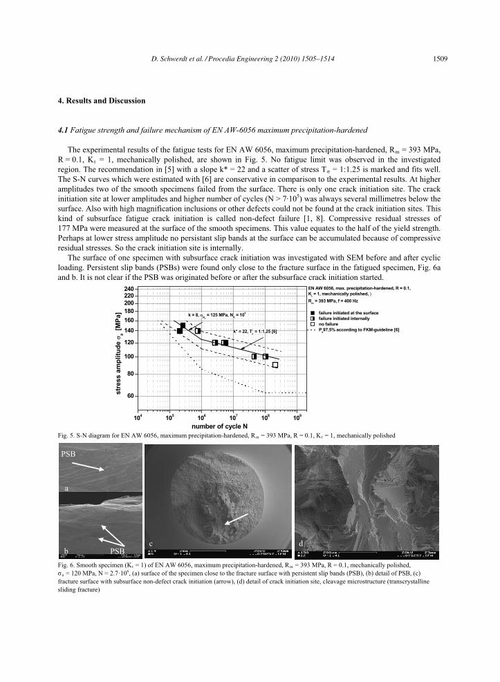
The experimental results of the fatigue tests for EN AW 6056, maximum precipitation-hardened, Rm = 393 MPa, R = 0.1, Kt = 1, mechanically polished, are shown in Fig. 5. No fatigue limit was observed in the investigated region. The recommendation in [5] with a slope k* = 22 and a scatter of stress T = 1:1.25 is marked and fits well. The S-N curves which were estimated with [6] are conservative in comparison to the experimental results. At higher amplitudes two of the smooth specimens failed from the surface. There is only one crack initiation site. The crack initiation site at lower amplitudes and higher number of cycles (N > 7·105) was always several millimetres below the surface. Also with high magnification inclusions or other defects could not be found at the crack initiation sites. This kind of subsurface fatigue crack initiation is called non-defect failure [1, 8]. Compressive residual stresses of 177 MPa were measured at the surface of the smooth specimens. This value equates to the half of the yield strength.Perhaps at lower stress amplitude no persistant slip bands at the surface can be accumulated because of compressive residual stresses. So the crack initiation site is internally.
The surface of one specimen with subsurface crack initiation was investigated with SEM before and after cyclic loading. Persistent slip bands (PSBs) were found only close to the fracture surface in the fatigued specimen, Fig. 6a and b. It is not clear if the PSB was originated before or after the subsurface crack initiation started.
60
80
100
120
140
160
180
200
220240
104
105
106
107
108
109
EN AW 6056, max. precipitation-hardened, R = 0.1,
Kt = 1, mechanically polished, )
Rm = 393 MPa, f = 400 Hz
failure initiated at the surface
failure initiated internally
no failure
Ps97,5% according to FKM-guideline [6]
number of cycle N
str
es
s a
mp
litu
de
a [
MP
a] k = 8,
NK
= 125 MPa, NK = 10
6
k* = 22, T = 1:1,25 [6]
Fig. 5. S-N diagram for EN AW 6056, maximum precipitation-hardened, Rm = 393 MPa, R = 0.1, Kt = 1, mechanically polished
Fig. 6. Smooth specimen (Kt = 1) of EN AW 6056, maximum precipitation-hardened, Rm = 393 MPa, R = 0.1, mechanically polished, a = 120 MPa, N = 2.7·106, (a) surface of the specimen close to the fracture surface with persistent slip bands (PSB), (b) detail of PSB, (c)
fracture surface with subsurface non-defect crack initiation (arrow), (d) detail of crack initiation site, cleavage microstructure (transcrystallinesliding fracture)
a
PSB
b PSBc d
D. Schwerdt et al. / Procedia Engineering 2 (2010) 1505–1514 1509
6 Schwerdt et al./ Procedia Engineering 00 (2010) 000–000
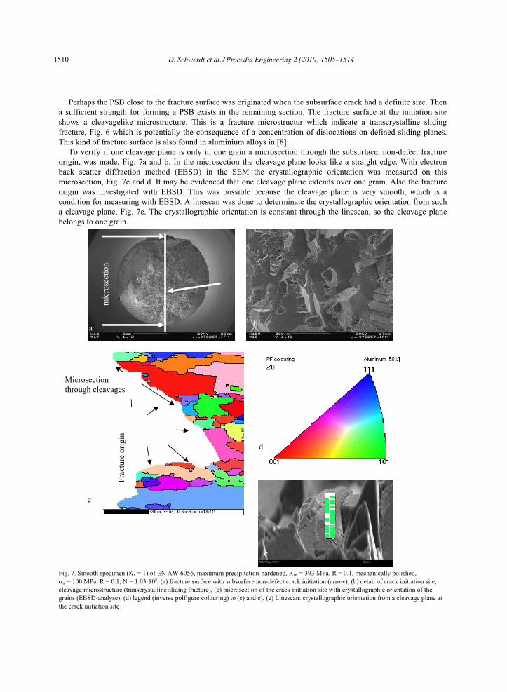
Perhaps the PSB close to the fracture surface was originated when the subsurface crack had a definite size. Then a sufficient strength for forming a PSB exists in the remaining section. The fracture surface at the initiation site shows a cleavagelike microstructure. This is a fracture microstructur which indicate a transcrystalline sliding fracture, Fig. 6 which is potentially the consequence of a concentration of dislocations on defined sliding planes. This kind of fracture surface is also found in aluminium alloys in [8].
To verify if one cleavage plane is only in one grain a microsection through the subsurface, non-defect fracture origin, was made, Fig. 7a and b. In the microsection the cleavage plane looks like a straight edge. With electron back scatter diffraction method (EBSD) in the SEM the crystallographic orientation was measured on this microsection, Fig. 7c and d. It may be evidenced that one cleavage plane extends over one grain. Also the fracture origin was investigated with EBSD. This was possible because the cleavage plane is very smooth, which is a condition for measuring with EBSD. A linescan was done to determinate the crystallographic orientation from such a cleavage plane, Fig. 7e. The crystallographic orientation is constant through the linescan, so the cleavage plane belongs to one grain.
mic
rose
ctio
n
ba
Fig. 7. Smooth specimen (Kt = 1) of EN AW 6056, maximum precipitation-hardened, Rm = 393 MPa, R = 0.1, mechanically polished, a = 100 MPa, R = 0.1, N = 1.03·108, (a) fracture surface with subsurface non-defect crack initiation (arrow), (b) detail of crack initiation site,
cleavage microstructure (transcrystalline sliding fracture), (c) microsection of the crack initiation site with crystallographic orientation of the grains (EBSD-analyse), (d) legend (inverse polfigure colouring) to (c) and e), (e) Linescan: crystallographic orientation from a cleavage plane at the crack initiation site
Frac
ture
orig
in
Microsectionthrough cleavages
d
c
e
1510 D. Schwerdt et al. / Procedia Engineering 2 (2010) 1505–1514
Schwerdt et al./ Procedia Engineering 00 (2010) 000–000 7
4.2 Influence of notches
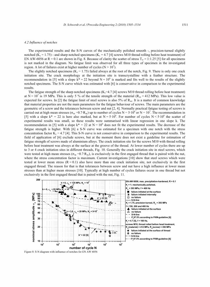
The experimental results and the S-N curves of the mechanically polished smooth -, precision-turned slightly notched (Kt = 1.75) - and sharp notched specimens (Kt = 4.7 [4] screws M10 thread rolling before heat treatment) of EN AW-6056 at R = 0.1 are shown in Fig. 8. Because of clarity the scatter of stress T = 1:1.25 [5] for all specimens is not marked in the diagram. No fatigue limit was observed for all three types of specimen in the investigated region. A lot of failures exist at higher number of cycles (N > 107).
The slightly notched specimens (Kt = 1.75) failed always at the root of the notch, Fig. 9. There is only one crack initiation site. The crack morphology at the initiation site is transcrystalline with a feather structure. The recommendation in [5] with a slope k* = 22 beyond N = 106 is marked and fits well to the results of the slightly notched specimens. The S-N curve which was estimated with [6] is conservative in comparison to the experimental results.
The fatigue strength of the sharp notched specimens (Kt=4.7 [4] screws M10 thread rolling before heat treatment) at N = 107 is 19 MPa. This is only 5 % of the tensile strength of the material (Rm = 412 MPa). This low value is expected for screws. In [2] the fatigue limit of steel screws is also 5% of Rm. It is a matter of common knowledgethat material properties are not the main parameters for the fatigue behaviour of screws. The main parameters are the geometric of a screw and the tolerances between screw and nut [2, 4]. Normally practical fatigue testing of screws is carried out at high mean stresses ( m =0.7·Rm) up to number of cycles N = 5·106 or N = 107. The recommendation in [5] with a slope k* = 22 is here also marked, but at N = 5·106. For number of cycles N < 5·106 the scatter of experimental results was small, so these results were summarised with linear regression in one slope k. The recommendation in [5] with a slope k* = 22 at N = 106 does not fit the experimental results. The decrease of the fatigue strength is higher. With [6] a S-N curve was estimated for a specimen with one notch with the stress concentration factor Kt = 4.7 [4]. This S-N curve is not conservative in comparison to the experimental results. The field of application of [6] exclude screws, but at the moment there does not exist a guideline for estimation of fatigue strength of screws made of aluminium alloys. The crack initiation site for the screws M10 with thread rolling before heat treatment was always at the surface at the groove of the thread. At lower number of cycles there are up to 3 or 4 crack initiation sites in different threads, Fig. 10. Generally the crack initiation site in steel screws, which were tested at high mean stresses ( m =0.7·Rm), is exclusively in the first engaged thread that is paired with the nut, where the stress concentration factor is maximum. Current investigations [10] show that steel screws which were tested at lower mean stress (R = 0.1) also have more than one crack initiation site, not exclusively in the first engaged thread. The reason for that is that tolerances between screw and nut have a high influence at lower mean stresses than at higher mean stresses [10]. Typically at high number of cycles failures occur in one thread but not exclusively in the first engaged thread that is paired with the nut, Fig. 11.
10
20
30
40
50
60
708090
100
200
104
105
106
107
108
109
k* = 22 [6]
k = 3,8, N
K
= 20 MPa, NK = 5•10
6
k = 8, N
K
= 85 MPa, NK = 10
6
k* = 22 [6]
k = 8, N
K
= 125 MPa, NK = 10
6
number of cycle N
no
min
al s
tre
ss
am
plitu
de
a [
MP
a]
EN AW 6056; max. precipitation-hardened; R = 0.1
2 DL
Kt = 4.7 [5], f = 160 Hz,
screws M10, thread rolled before head treatment,
Rm(material) = 412 MPa, R
m(screw) = 350 MPa
failure initiated at the surface of thread
no failure
S-N-line
Pü97.5% according to FKM-guideline [6]
Kt = 1.75, precision-turned, R
m = 393 MPa
f = 150, 200 and 400 Hz
failure initiated at the surface
no failure
S-N-line
Pü97.5% according to FKM-guideline [6]
Kt = 1; mechanically polished,
Rm = 393 MPa; f = 400 Hz
failure initiated at the surface
failure initiated internally
no failure
S-N-line
Figure 8: S-N diagram with influence of notches for EN AW 6056
D. Schwerdt et al. / Procedia Engineering 2 (2010) 1505–1514 1511

8 Schwerdt et al./ Procedia Engineering 00 (2010) 000–000
a b
Figure 9: Slightly notched specimen, Kt = 1.75, of EN AW 6056, maximum precipitation-hardened, Rm = 356 MPa, R = 0.1 , precision-turned,a = 70 MPa, N = 1.25·106, (a) fracture surface with failure initiated at the surface of the notch (arrow), (b) detail of crack initiation site
(transcrystalline with feather structure)
Figure 10: Sharp notched specimen, Kt = 4.7, screw M10 thread rolling before heat treatment, EN AW 6056, Rm (material) = 412 MPa, Rm (screw) = 396 MPa R = 0.1 , a = 33 MPa, N = 6.37·105, (a) fracture surface with failure initiated at multiple grooves of thread (examples: arrows), b) detail of one crack initiation site (transcrystalline with feather structure)
Figure 11: Sharp notched specimen, Kt = 4.7 [4], screw M10 thread rolling before heat treatment, EN AW 6056, Rm (material) = 412 MPa, Rm (screw) = 396 MPa, R = 0.1 , a = 16 MPa, N = 1.94·108, (a) fracture surface with failure initiated at one groove of thread (arrow), (b) detail of crack initiation site (transcrystalline with feather structure)
ba
a b
1512 D. Schwerdt et al. / Procedia Engineering 2 (2010) 1505–1514
Schwerdt et al./ Procedia Engineering 00 (2010) 000–000 9
4.3 Influence of compressive residual stresses
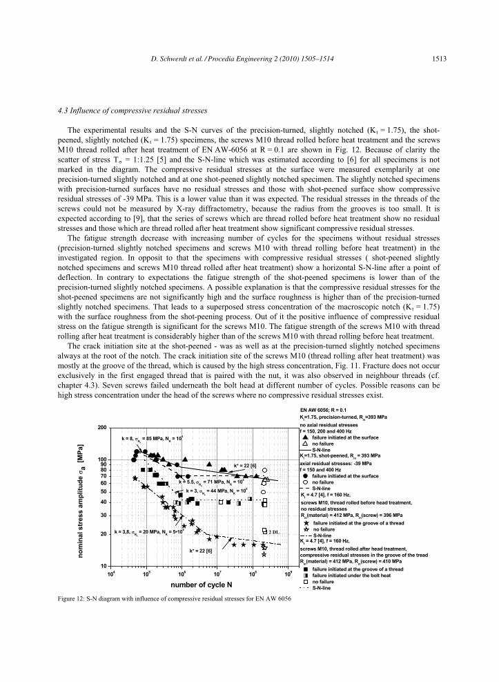
The experimental results and the S-N curves of the precision-turned, slightly notched (Kt = 1.75), the shot-peened, slightly notched (Kt = 1.75) specimens, the screws M10 thread rolled before heat treatment and the screws M10 thread rolled after heat treatment of EN AW-6056 at R = 0.1 are shown in Fig. 12. Because of clarity the scatter of stress T = 1:1.25 [5] and the S-N-line which was estimated according to [6] for all specimens is not marked in the diagram. The compressive residual stresses at the surface were measured exemplarily at one precision-turned slightly notched and at one shot-peened slightly notched specimen. The slightly notched specimens with precision-turned surfaces have no residual stresses and those with shot-peened surface show compressive residual stresses of -39 MPa. This is a lower value than it was expected. The residual stresses in the threads of the screws could not be measured by X-ray diffractometry, because the radius from the grooves is too small. It is expected according to [9], that the series of screws which are thread rolled before heat treatment show no residual stresses and those which are thread rolled after heat treatment show significant compressive residual stresses.
The fatigue strength decrease with increasing number of cycles for the specimens without residual stresses (precision-turned slightly notched specimens and screws M10 with thread rolling before heat treatment) in the investigated region. In opposit to that the specimens with compressive residual stresses ( shot-peened slightly notched specimens and screws M10 thread rolled after heat treatment) show a horizontal S-N-line after a point of deflection. In contrary to expectations the fatigue strength of the shot-peened specimens is lower than of the precision-turned slightly notched specimens. A possible explanation is that the compressive residual stresses for the shot-peened specimens are not significantly high and the surface roughness is higher than of the precision-turned slightly notched specimens. That leads to a superposed stress concentration of the macroscopic notch (Kt = 1.75) with the surface roughness from the shot-peening process. Out of it the positive influence of compressive residual stress on the fatigue strength is significant for the screws M10. The fatigue strength of the screws M10 with thread rolling after heat treatment is considerably higher than of the screws M10 with thread rolling before heat treatment.
The crack initiation site at the shot-peened - was as well as at the precision-turned slightly notched specimens always at the root of the notch. The crack initiation site of the screws M10 (thread rolling after heat treatment) was mostly at the groove of the thread, which is caused by the high stress concentration, Fig. 11. Fracture does not occur exclusively in the first engaged thread that is paired with the nut, it was also observed in neighbour threads (cf. chapter 4.3). Seven screws failed underneath the bolt head at different number of cycles. Possible reasons can be high stress concentration under the head of the screws where no compressive residual stresses exist.
10
20
30
40
50
60
708090
100
200
104
105
106
107
108
109
Kt = 4.7 [4], f = 160 Hz,
screws M10, thread rolled after head treatment,
compressive residual stresses in the groove of the tread
Rm(material) = 412 MPa, R
m(screw) = 410 MPa
failure initiated at the groove of a thread
failure initiated under the bolt heat
no failure
S-N-line
no
min
al s
tres
s a
mp
litu
de
a
[M
Pa]
k = 3, N
K
= 44 MPa, NK = 10
6
k = 5.5, N
K
= 71 MPa, NK = 10
6
Kt=1.75, shot-peened, R
m = 393 MPa
axial residual stresses: -39 MPa
f = 150 and 400 Hz
failure initiated at the surface
no failure
S-N-line
k* = 22 [6]
k = 3,8, N
K
= 20 MPa, NK = 5•10
6
k = 8, N
K
= 85 MPa, NK = 10
6
k* = 22 [6]
number of cycle N
EN AW 6056; R = 0.1
2 DL
Kt = 4.7 [4], f = 160 Hz,
screws M10, thread rolled before head treatment,
no residual stresses
Rm(material) = 412 MPa, R
m(screw) = 396 MPa
failure initiated at the groove of a thread
no failure
S-N-line
Kt=1.75, precision-turned, R
m=393 MPa
no axial residual stresses
f = 150, 200 and 400 Hz
failure initiated at the surface
no failure
S-N-line
Figure 12: S-N diagram with influence of compressive residual stresses for EN AW 6056
D. Schwerdt et al. / Procedia Engineering 2 (2010) 1505–1514 1513
10 Schwerdt et al./ Procedia Engineering 00 (2010) 000–000
a b c
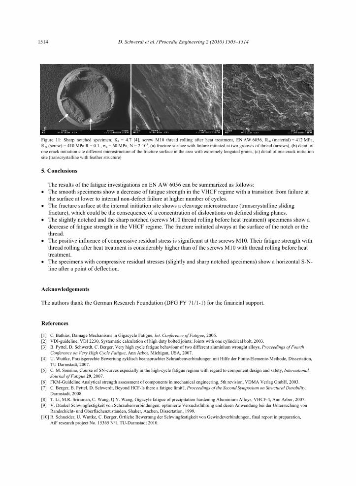
Figure 11: Sharp notched specimen, Kt = 4.7 [4], screw M10 thread rolling after heat treatment, EN AW 6056, Rm (material) = 412 MPa, Rm (screw) = 410 MPa R = 0.1 , a = 60 MPa, N = 2·108, (a) fracture surface with failure initiated at two grooves of thread (arrows), (b) detail of one crack initiation site different microstructure of the fracture surface in the area with extremely longated grains, (c) detail of one crack initiation site (transcrystalline with feather structure)
5. Conclusions
The results of the fatigue investigations on EN AW 6056 can be summarized as follows: The smooth specimens show a decrease of fatigue strength in the VHCF regime with a transition from failure at the surface at lower to internal non-defect failure at higher number of cycles. The fracture surface at the internal initiation site shows a cleavage microstructure (transcrystalline sliding fracture), which could be the consequence of a concentration of dislocations on defined sliding planes. The slightly notched and the sharp notched (screws M10 thread rolling before heat treatment) specimens show a decrease of fatigue strength in the VHCF regime. The fracture initiated always at the surface of the notch or the thread. The positive influence of compressive residual stress is significant at the screws M10. Their fatigue strength with thread rolling after heat treatment is considerably higher than of the screws M10 with thread rolling before heat treatment. The specimens with compressive residual stresses (slightly and sharp notched specimens) show a horizontal S-N-line after a point of deflection.
Acknowledgements
The authors thank the German Research Foundation (DFG PY 71/1-1) for the financial support.
References
[1] C. Bathias, Damage Mechanisms in Gigacycle Fatigue, Int. Conference of Fatigue, 2006. [2] VDI-guideline, VDI 2230, Systematic calculation of high duty bolted joints; Joints with one cylindrical bolt, 2003. [3] B. Pyttel, D. Schwerdt, C. Berger, Very high cycle fatigue behaviour of two different aluminium wrought alloys, Proceedings of Fourth
Conference on Very High Cycle Fatigue, Ann Arbor, Michigan, USA, 2007. [4] U. Wuttke, Praxisgerechte Bewertung zyklisch beanspruchter Schraubenverbindungen mit Hilfe der Finite-Elemente-Methode, Dissertation,
TU Darmstadt, 2007. [5] C. M. Sonsino, Course of SN-curves especially in the high-cycle fatigue regime with regard to component design and safety, International
Journal of Fatigue 29, 2007. [6] FKM-Guideline Analytical strength assessment of components in mechanical engineering, 5th revision, VDMA Verlag GmbH, 2003.[7] C. Berger, B. Pyttel, D. Schwerdt, Beyond HCF-Is there a fatigue limit?, Proceedings of the Second Symposium on Structural Durability,
Darmstadt, 2008. [8] T. Li, M.R. Sriraman, C. Wang, Q.Y. Wang, Gigacyle fatigue of precipitation hardening Aluminium Alloys, VHCF-4, Ann Arbor, 2007. [9] V. Dünkel Schwingfestigkeit von Schraubenverbindungen: optimierte Versuchsführung und deren Anwendung bei der Untersuchung von
Randschicht- und Oberflächenzuständen, Shaker, Aachen, Dissertation, 1999. [10] R. Schneider, U. Wuttke, C. Berger, Örtliche Bewertung der Schwingfestigkeit von Gewindeverbindungen, final report in preparation,
AiF research project No. 15365 N/1, TU-Darmstadt 2010.
1514 D. Schwerdt et al. / Procedia Engineering 2 (2010) 1505–1514


![Experimental Study on Fatigue Characteristics for ... · Low-cost, light weight aluminium matrix composites have a good potential for application to aerospace structures [1]. Aluminium](https://img.pdfslide.us/doc/110x75/5f5adb415bbfce6fdc762096/experimental-study-on-fatigue-characteristics-for-low-cost-light-weight-aluminium.jpg)


![[Elsevier] Review of Fatigue Assessment Procedures for Welded Aluminium Structures](https://img.pdfslide.us/doc/110x75/577cc2d01a28aba711948efd/elsevier-review-of-fatigue-assessment-procedures-for-welded-aluminium-structures.jpg)