Embed Size (px)
Citation preview

8/10/2019 Fatigue Resistance of Oxygen Cut Steel
http://slidepdf.com/reader/full/fatigue-resistance-of-oxygen-cut-steel 1/6
•
WELDING
RESEARCH
SUPPLEMENT
TO
THE WELDINC JOURNAL, AUCUST 1977
Sponsored
by the merican
Welding
Society
and the Welding
Research
Council
Fatigue Resistance
o
Oxygen ut Steel
atigue
life
s
strongly
influenced
by
oxygen
cut
surface
roughness and fractography indica tes that resolidified
metal deposits at the torch edge of a cut may often be
the si te
of fatigue crack
initiation
BY
R.
PLECKI
R. YESKE
C.
ALTSTETTER AND F V.
LAWRENCE
JR.
Oxygen cut surfaces of
roughnesses were pre
Fatigue specimens of high
trength, low
alloy
ASTM A572) and
, quenched-and-tem
ASTM A514) grades
of
steel ·
prepared
with four
controlled
Load-controlled
were performed using a
stress cycle. The sur
face roughness was quantified by the
MS deviation from
flatness , and
the
microstructures were
metallographically and
microhardness measurements.
Fatigue
life
was
found
to be strongly
influenced by roughness, and to differ
by
as
much
as
an
order
of magnitude
etween rough and smooth surfaces at
the lowest stress leve
ls.
Fractography
indicated
that resolidified metal de
osits at the torch edge of the cut were
often the site
of
fatigue crack
initia
tion .
The effect of oxygen cutting on
fatigue
life
could be qualitatively
understood on the basis of the stress
oncentration resulting from an array
of
surface notches.
Introduction
The oxygen
cutting of
thi ck steel
sect ions is
an economical alternative
to other cutting and shaping
methods
,
particularly if little further machining
or
grinding of the cut edge is required.
In fatigue applications, the surface and
sub-surface regions exert a strong
influence
on behavior; thu s, it is
necessary to
assess
the i m pact
of
oxygen cutting in these regions. In
addition to the modification of surface
properties
due
to chemical changes,
microstructural
changes and changes
in the state of residual stress, changes
in geometrical features such as rough
ness, gouges, drag lines,
melted
beads
and cracks may be introduced by
oxygen
cutting.
The effect of oxygen cutting
on
fatigue life has been previously stud
ied in
mi
Id steel
having
a ferrite
pearlite microstructure,
and results
of
different investigators vary widely.'-
Processing variables have been found
to significantly modify the steel hard
ness and microstructure.
However
,
these
va
riables have
not
always been
sys tematically controlled, and the state
of the metal has been
quite
variable.
R. PLECKI is Researeh Assistant R. YESKE is
Assistant Prol essor C
ALTSTETTER
is
Pro-
lessor Department 01 Metallurgy nd
Minin g and
F V. LA
WRENCE
IR
is Asso
eiate Prolessor Departmenls 01 Civil Engi-
neering and Metallurgy nd Mining Uni
versily
01
lIIinois at Urbana-Champaign
Urbana /llin ois.
For example, Koenigsberger
2
and co
workers have reported both the pres
ence and the absence
of
significant
surface
hardening
, sub -surface
soften
ing, and through-thickness softening
32 mm) for different suppliers of
oxyge n cut specimens. The
Nether
lands
group'
has reported surface
hardnesses ranging
from 245
VHN
to
well
over
double
that value
as
a result
of changes in preheating procedure,
nozzle type, gas type and pressu
re s,
and cutting speed. Even Goldberg,'
who
defined surface quality and care
fully quantified
the
surface roughness,
found
wide variability in hardness
changes.
Despite
these changes in
the
mate
rial, the generally held view is that
excessive surface rough ness decreases
the fatigue
life
, and surface
rough
ening is the most important result of
oxygen cutting.
The
principal
objective of the pres
ent work was to extend the current
knowledge
of
fatigue
behavior of
oxygen cut surfaces to a
higher
stress
regime. Thus high strength , low alloy
ASTM A572) and quenched-and
tempered steels ASTM A514) were
investigated at short lifetimes . Surface
roughness was varied in a
controlled
manner. The
microstructure
and hard
ness profiles were
determined
for each
roughness and steel type. The fatigue
WELDINC RESEARCH SUPPLEMENT 225-s

8/10/2019 Fatigue Resistance of Oxygen Cut Steel
http://slidepdf.com/reader/full/fatigue-resistance-of-oxygen-cut-steel 2/6
Table
I-Mechanical
Properties
Material
A572
1
A5'14
1
A514 (normalized)lb '
Yield
Ultimate
stra n
strength
strength at fracture
5)',
ksi
5 , ksi
e
r
,
%
55
79 23
108.3
119 .0 15.2
52.0
o
( ISupplied y manufacturero .
( Ove(all spec imen length 12 in. 1 in . gage lenglh, 0.5 in. d a meler
redLJ
ced sectlon.
results could be rationalized by the
stress concentration e ff ects of a peri
odic
array of notc hes .
Experimental Procedure
Two structural steels were obtained
as 1 in . (25
mm) th i
ck
pl
at
e. One
wa s
co mparable
to
ASTM A572 grade 42
0.22% ma x. ca rb on,
42
ksi (290 MPa)
minimum yield
s
trength, and the
second
was
a
quenched-and-tem
pered steel
which
conformed to
ASTM
A514 grade e (0.2 max. carbon ,
0.005% max.
boron
, 100 k
si
(609
MPa)
minimum yield
strength).
The
tensile
properties
of these
mate
rials are given
in
Table 1.
The
pl ates
were cut
into
12 in. (305 mm) sq uares
and
mill
ed to the cross-sec tion shown
in
Fig
1.
Speci
mens
of a varying
rough
ne
ss
were
ox
yge n cut from these
blanks by moving
them
beneath a
cutting torch whi ch was oscillated at
different amplitudes
and
frequencies.
The cutting
parameters were
as
follows 1 ti p , propylene gas at 5 psig
(34 KP a), preheat oxygen at 7 psig (48
KP
a), c
utting
o xyge n at 50 psig (345
KPa), average
cutting
speed 9 ipm (3.8
mm /
s)
and
torch
tip
to
metal separa
tion of 1/ 4 in. (6 mm ) . After cutting,
one side of the specimen was milled
parallel
to the
opposite
oxygen cut
surface
to
give a
3/4
in .
sq uare
test
sect ion. AII spe ci mens
were
wire
brushed by
hand
before testing . Spec
imens were
mounted in
an MTS
machine using se lf-alignin g grips
and
were fatigue tested using a ze ro-to
tension
stress cycle
(R
= O
under load
co
nt r
o l at 5-'15 Hz .
The
contour
of the oxygen cut
surface of each spec imen wa s m ea
sured using an
LVDT
profilom eter with
a tungsten ca
rbide
stylus inc
lined
30
degrees
from
the surface normal.
Profile traces were reco
rded
at
the
midpoint and
at the melted
(upper)
edge.
The
RMS
amplitude
of
deviation
from
flatness
was
used
to characterize
the
notch-p
eak di str
ibution
.
Figure 2 sho
ws
traces
and photo
graphs of the four rou g
hn
ess levels
used in
this
s
tudy:
0.001 , 0.002, 0.007,
and
0.011
in
. (25
,50,180,
and 280
,um .
Triplicate
fatigue te sts were run at
each of
two
stress levels
and
four
roughness leve ls for each steel. Spec
imens of th e quenched-and-tempered
steel were also
normali
zed afte r oxy
gen c
uttin
g and then tes
ted
. A l imited
number of tests wer e also performed
on
machined
specimens.
Followi
ng fatigu e testi ng, selec
ted
spec imens were sec tioned and
mounted fo r op ti ca l
metallograph
y
and SEM fra c tograph
y. Microhardness
profil
es
n
orm
al
to th
e oxyge n cut
surface
were determin ed using a
Fleme Cul
Surfece
7
Radius (Machined)
6
1
- 12 ~
Flame Cul Surface
Machined
Surfaces
Fig. 1 Specimen
geo
metr
y
226 s I
AUGUST
19
77
Kno
op
indenter
and 100 gram (gm)
load.
Results
Metallography and Microhardness
O xygen
cutt
ing produces a var ie ty
of
micro
struc tures and several
kind
s of
hardness
profile.
At
many po in ts along
the surface of either stee l,
th
ere
was
a
decarburized laye r, p
ar t
icularly where
oxide droplet
s
had
so
lidified
on the
s
urface.
Th ese nodules
of resolidifi
ed
metal were invariabl y
de
ca
rburized
and
were light etched
with
3% nital
Fig . J
Microhardness
mea surements
verifi ed that these region s were much
so fter than the adJacent metal. Furth er
ev
idence
of deca rburi za tion
wa
s th e
absence of pea rlit e
in
these re g ions
after spec
imen
s
were normalized
(in
vacuum).
Below
th e
decarburized zone was
a
relati
ve
ly
hard
zone in both steels. In
A572 steel, the mi c ro
co
nst i tuent wa s
ac icular,
and it
s cha
racter
chan ged
from coarse
\lVidmanstatten
ferrite ju
st
under the
surface to the
appearan
ce
of
bainite
a
nd
th en marten site . In the
A514 steel, j ust under the decarburized
zone was a
dark
etching,
fine
grained,
m art ensitic zone extending
to
about
0.04 in. (1.0 mm)
below the
surface.
Beyond this zo ne was the intercriti ca l
heat affected zone
(HAZ),
con sis ting
of coarse
fe
rrit
e
grains with
som e
very
fine
pear
li t
e
colonies
at th e
grain
boundaries.
In
one s
pecimen
of A514,
there
was
a second zone of coa rse ferrite and
pearlite
at
0.
14-0.18
in. (3.6
to
4
.6
mm) .
Other
specimens of A514 showed only
a single suc h zone. The intercr it ica l
HAZ
in th e A572 steel extended from
about 0.06
to
0.10
in
. (1.5
to
2.5 mm)
below
the surface. In both stee ls, the
HAZ ex tended as mu ch as 0.2 in. (5
mm) below th e surface.
Figures 4
and
5 are microhardn
ess
traverses across
th
e HAZ
of
a sa
mple
of
each type o f stee l.
There
wa s a mo re
distinct tend enc y for the A514 to
show
plateaus of hardness which co uld be
co
rre
lated to the different
microstruc
tur
es.
In
A572
under
the martensiti
c
zone,
there
was a
general decrea se
in
hardness which fol lowed the observed
modificati o ns o f
pearlite
in a
ferrit
e
matrix.
Fatigue
Test
Results
The
res
ul t
s
of th
e
fatigue te
sts for
the two
steels are plotted
in
Fi gs . 6 and
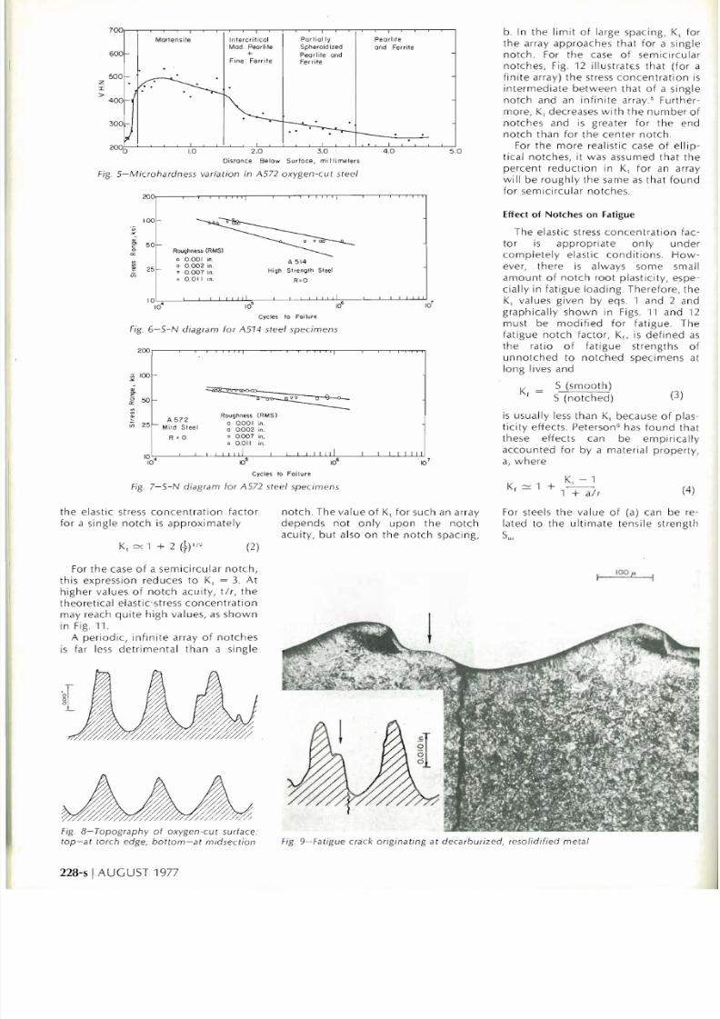
7. The RMS rough ness was meas ured
for
eac h fa tigue specim en and the
po
in t
s in Figs. 6
and
7 a re
co
rre s
pond
ingl
y
identified.
A
numb
er
of
spec
imens
broke
in the grips, thereby
decreasing
th
e numb er of data points
somewhat. Fo r this reason , sca tt er

8/10/2019 Fatigue Resistance of Oxygen Cut Steel
http://slidepdf.com/reader/full/fatigue-resistance-of-oxygen-cut-steel 3/6
Pii'U
" t i
1 ' MX I «
=§ f
1
in
the SEM
at
up
to X 1000,
the
oxygen
cut surfaees were smoothl y eo ntoured
in some plaees and dendritie in others.
The fatigue craeks
were often
seen to
:§f
1.0
l
have
not
been
ass igned
in a
s way. The lines in Figs.
6
and
7
least-squa res fit s for the roughest
smoot
he
st
spee
imen
s.
of the
re
sul ts for the
cut surfaee (Figs.
6
7)
shows that the
higher st
rength
has a higher fatigue
istanee than the A572 at 10 eyeles.
lO
eyele
s t
he fatigue strengths of
and A572 steels are
for
all
identi
ea l.
The A514 steel
a greater sensitivity to rough
cut surfaees in that for a given
life the
allowable
stress level
more
severely by a
oxygen-eut in A514 than in A572
is
partly
due to
the greater
of the S-N plot
for
A514.
fatigue failures almost always
at the upper edge, elosest to
to r
eh.
At
thi s edge there was
more reso lidified metal. At
s
point
al
so
, there is a le
ss
regular
aph y with somewhat greater
S roughn ess- Fig. 8.
gure 9 shows a crack in A514 steel
at ing at the edge of a deearburized
on the surfaee. When viewed
Fig
J- Oxide layer A) al oxygen cul
surface
01
A574 sleel specimen adjacenl to
underl
ying
dec
a
rburized zone
(8)
follow the interdendriti c spaces and
the boundary between
smooth
and
dendritie areas. The fracture surfaees
them se
lve s s
howed
largel y transgran
ular craeks with so me crack braneh
ing.
Discussion
Stress Concentration al Nolches
The simplest
treatment
of the effect
of oxygen eutting on fatigue is to
disregard all
but
the geometrieal
features of the oxygen
cut
surfaee. A
model for the effeet
of
oxygen
eutting
was
developed
by assuming that th e
surfaee co ntour can be approximated
as
a se rie s of notehes.
Assuming
elastie
behavior,
the
theoretieal stress eon
een tration factor, K at a single noteh
tip is
defined simply
as
the
ratio of
the
maximum
longitudinal
stress at
the tip,
to the average, remote stress, S
K,
= oi
1 )
For an elliptieal surfaee noteh
of
depth
, t, and
root
radius, r (see Fig. 10)
l. 0.10 .1
.
2 Prol
ilomele
r lraces a
nd
ma
crograp
hs 01
lhe tour oxygen cul
surfaces s
ludied
600
500
.
...
.
e e
Z
I
>
400
300
.......
. .
200
0
Dislance Below Surface. mill imelers
Fig 4- 0 xygen cul sur lace 01 A514 slee l
specimen
: lop micros
lru
clural modilication s;
bOllom microhardness variation
8/10/2019 Fatigue Resistance of Oxygen Cut Steel
http://slidepdf.com/reader/full/fatigue-resistance-of-oxygen-cut-steel 4/6
b.
In
the
limi
t
of
large spaci ng, K,
for
the array approaches
that
for
a s
ingle
no t
ch. For the c
ase
of
se
mi
c irc
ular
no t
ches, Fi
g.
12 illu strat
E:s
that
for a
finite
arra y )
the
stress conce
nt r
ation is
interm
ed iate
between
that
o f a s
in
gle
no tch and an
infin
ite array Further
more
, K decreases w
ith the num ber of
notches
and is greater for
the
end
notch
than for the
center notch.
For
the more
realistic case
of ellip
tical
notches,
it wa s
assu
med
that the
percent
reduction in
K for an
array
will
be
roughly
the same as
that found
for semicircul
ar
notche
s.
Effect of
Notches
on Fatigue
The elastic st
re
ss co nce
ntr
ation fac
tor
is
appropriate onl
y
under
co
mplet
ely elast ic
conditions
.
Ho
w
ever, th ere is always so me small
amount of no t
ch
root plasticity
, espe
cially in fati gue l
oad
ing. The refore, the
K
va
lues given
by
eqs.
1
and
2
and
graphically
shown
in Figs.
11
and
12
must be
modified for
fatigue. The
fatigue
notch
factor, K is
defined as
the ratio
of
fatigu e stre
ngth
s
of
unnotched to notch
ed specim ens at
long I ves and
K - S
(sm
oo
th)
f -
S
notched)
(3)
is usually le
ss
than K because
of
pl
as
ticit
y eHects. Peterso n
G
has
found
that
these eHects can be empirically
acco
unted
for
by
a
mat
e
ri
al
property,
a, w here
K, - 1
K
f
1 +
(4)
1 + al
r
For steels
the
value of (a) can be re
lated to the
ultimate
ten sil e strength
Su
lOO/:
6
5
Z
I
>
4
3
Partially Pearl,te
ntercritical
arlensi
le
Mod. Pearlile
Spheroid
ized
and Ferrite
+
Pearlite and
Fine Ferrite
Ferrite
OiSfance 8elow Surfoce
mi
llimelers
Fig
5 Microh
ardne
ss va
riation
in A572
oxygen cut
steel
1
'
5Or
o
a:
Roughne
IRMSI
0 .001
in
.
A 514
o 0 .002 in .
25 r-
HiQh
Strength Sleel
v
0 .
007 in .
Vi
l 0 .0 .
RoO
, 1
1
10 •
10
10
la·
iO
Cyc les lo Failure
Fi
g
6- S- N diagram lo r A514 steel
specimens
100
Vi 25
Fig
. 7
N
diagram lor
A572 stee l s
pe
c
imens
Roug hness (R MSI
o 0.
001
in.
- ¿ s ~ e e l
o 0.
002
in.
. 0.007
in
l
0.
011 in .
RoO
, 1
lO
Cyc les lo Foilure
th e elast ic stress
concentr
ation
factor
fo r a sing le
notch is
approxim ately
For
the
case
of
a
semicircular not
ch,
this expression reduces to K, = 3. At
hi gher
va
lues
of notch
acuity,
t
the
theo ret ical elastie-stress
concentration
may reach
quite hi
gh
va
lue
s,
as
s
ho
w n
in
Fig. 11
.
A
periodic
,
infinite
array
of
no tc
he
s
is far l
ess detrimental than
a s
in
gle
notch.
The
value
of
K
for
such
an
array
depends not
only
upon th
e
no
tc h
ac uity, but
also
on the notch
spacing,
Fi
g. 8- Topograph y
oi
oxygen
cut
sur face .
top at
torch e
dge
, botlom
a t
midsectibn
228 5 IAUGUST 1977
Fig 9- Fatigue crack
originating
at
de
c
arburiz
ed, reso lidified metal
8/10/2019 Fatigue Resistance of Oxygen Cut Steel
http://slidepdf.com/reader/full/fatigue-resistance-of-oxygen-cut-steel 5/6
3.5
End Nolch of The Array
Middle Naleh of The Array
2.5
2.0
1 Y ./
~ ~ ~ l s ~ ~ ?TI-
a =
.
001
300 ) J.S
(5)
Su
e Su isgiven in ksi,and (a) is in
ch
es.
Fatigue Resistance 01 Oxygen Cut Surlace
Asseen in Figs.6 and 7 the fatigue
res istance
of
spec im ens with oxygen
ut surfac
es
decreased
with
increasing
roughness, particularly at longer lives,
the state
of
stress at the
notch
tip
s approaches elastic
conditions.
s
is
in agreeme
nt
with
previously
ted relationships.
In
orde r to place this trend on a
more
quantitative
basis, the
geomet-
i cal parameters, r, t, b and c were
lor
lhe different
roughness
levels tested. K, values
were
then
for both semicircular
and
l l ipti
ca l notches. Using the base
et
al
Su values for each steel, the
factorK,wascalculated
for both
semi
ircular and e
l l iptical notch
arrays
for
rough es t surfaces tested.
The calculated
va
lues are
shown
in
ab le 2 and
compared with
experi-
e
nt
all y
determined va
lues.The
latter
rees
timat
edusingeq. (3).
To mini-
z
e the
effect of micro
s
tructural
lteration due to oxygen cutting
,
the
Table 2-Comparison
01 Calculated and Measured
Fatigue Stress Concentration Factor,
K
,
( a l
Calc
ul
ated K,
Material
a
(in .)
Semi
c
ir
c
ul
ar E
lIipti
ca
l
.
Measured
K,
AS72
0.0'10
-130
-
1.83
1.28
AS
14
0.
0053
1.48
2. -
16
H8
AS
14
normalized)
0.012
1.
24
1.80
-1.53
tn)
K
r
a l u e ~
Jre l
or
roUglW ";l spec
im
ensl
es
led
(0.011
in .RMS) co
mpar
ed 10 smoo
the
sl specimens
lested (OJ)(JI
in .RMS).
200,
1 I
i
1 1 ' 1 1
i i
100f
"'
'"
<>
""
o::
50f
o __
"'
"'
"
Vi
25
f-
Roughness (RMS)
o 0.001 in.
A
514
Normolized Sleel
o 0.002 in .
o
0.007
in.
o 0.011
in
.
10
I 1
I
1 1 I
I I I I
!
I
lO·
10
5
10
6
Id
Cycles 10 Fai lure
Fig 13 S N di agram lo r no rmaliz ed A514 steel specimens
smoothes t oxygen c
ut
spec imen re
lhe
stresses
which
caused failure in
lO'
sul tswere taken for th e
numerator
and
cycles. Thesestresses
were
taken
from
the roug
he
st s
pe
c
imen
results
for the
the curves
of Figs.
6and 7. The close
denominator
.The
va lue
s
of
stre
ss were
agreement in Table 2
between
mea-
WELDING RESEARCH SUPPLEMENT I229-s
60
1 111111
b
l.
-1
K
,
2
l
' 1 1 1 11111 1
" 1
! ! ! t
1 2 4 6 8 10 20
40
~ ~ ~ "
tlr
Fig . 11 Elastic
s
tress concentration la cto r lor sing le sllrlace
notch
e
r
- - - - - , - - - - - , - - - - , - -1
b
l.
.1
K
,
S
~ 2 r
1.5
Infinile Array
S.
1.0':-'
_____- '-_____
-
_____L-____ J
o 34
b ~
b/c
1O
ellla l (lOp) and idealized oxygen cllt surlace topogra - Fig 12 Ela stic str
ess
co nc entration laclOr lor periodic arrays 01
ies
semicircul
ar surlac e no tch es
40
20
M i n ~ r T O )
, ,
r-.c in;
r
s-+ t.? $+
r : l ~
CT
max
CT
max

8/10/2019 Fatigue Resistance of Oxygen Cut Steel
http://slidepdf.com/reader/full/fatigue-resistance-of-oxygen-cut-steel 6/6
2 0 0 r - - - - - - - - - - - - - - - - - - - - - - - - - . - - - - - - - - - - - - ~
2 0 0 r . r ~
High Strength ~ t e e (A 514)
Mild Steel
(A
572)
"'
'
100
1001
---..
.
........
e
g 50f-
-
.
o
50 -
-
o
--- -- -
----.----
-
o;:
<f)
"'
25f
2 5 -
-
Rough
Flame
Cut
Surface
_ .
Raugh
Flame Cut Surfaee
f)
Smoo
th
Flame Cut
Sur
fa
ce
Smaoth Flame Cut Surface
Machined
Surfaee
f)
Maehined Su rfaee
I I
I
10
5
10
6
Id
10
5
10
6
Id
Cyeles
Cyeles
Fig .
14
Com
parison
01
machined and
ox
ygen cut
surlace
lati
gue
Fig.
75 C
omparison 01 machined and oxygen cut s
urf
ace fatigue
resiSlance - A514 sleel specimens
su red values of K, and th ose ca lculated
f
or an
array of semicircu lar notches
indicates tha t the
model
is va
lid
and
that th e approx
imations
are reason
able; however, further data wo uld be
useflll.
Accord in gly, spec imens
of
the A514
ste
el
we
re
norm alized after oxygen
cuttin g an d tested subsequen t to wire
brushing to remo
ve
th
e scale
from
the
n
ormaliz
in g treatments. Hard n
es
s
pro
fil es demonstrated
that
aside from
some decarbu ri zat i
on
at the sll rface
the hardn
ess
was uniformo The ten sil e
properties are
show
n in Table 1.
Fatigue results are shown in
Fig
. 13 and
experi men tal and calcul ated K¡ valu es
are co mp ared in Table
2.
Although the
agreement
is
not
as
good
as
for the
as
cut
s
ur f
ace
s,
it is qualitatively
cor
ree .
A
furthe
r
refinement
o f
the model
would be to take
into account the
layer of altered
microstructure
at the
surface of the flame
cut
spec imen
s.
Her e the hardness and S wou ld be
higher, a
nd
the
(a
) valu e
low
er. This
woul d have the effect of in cre asing
the calcu lat ed
K, va
lue s. It is felt that
such ref in ements are unjustified in th e
prese
nt wo
rk,
considering
the
approxi
mations which
have been used. The
si
tu ation
is
further complicat
ed by
the
chang es in geo
metr
y as
the
fat i
gue
crack propagates, by residu
al st
resses
and by simultaneo us changes in
microstructur
é' be
low
the surface.
Comparíson of Oxygen Cut
and
Machíned Surfaces
The ultimate
obje
ct ive of oxygen
cu
ttin
g is to achieve an economy in
fabrication; however, this mu st be
done with out un wa rranted degrada
tion in pro pert ies. In orde r to eva lu ate
the quality of
the trade-off between
economy
and pe
rforman
ce, co mp ari
sons we re made between oxygen cu t
an
d machined specimen s
for
the same
sp
ecim en geome try and nom in al
st
ress
230-5 I
AUGUS
T1 977
res is
t3nce A572
steel s
pe
c
im
ens
leve ls. A rough indication co uld be
obtained
by noting that
thr
ee of
the
lateral surfaces of the fatigue spec
imens we re machined and one was in
the oxygen cut co ndi t i
on
, yet nearly all
fat igue cracks initi ated
at
the oxygen
cut sur face. Further verifi
ca
t ion o f the
sup er iority of the mac hin ed surface
was
obta
in ed by performing a l imited
num
ber
of
fat igue tests on fu ll y
machin
ed spec
im
ens of
the
same
geometry, base metal and stress leve l.
Figures 14 and 15 show the re sul ts
for the machined spec imen s in com
parison w ith the lives for the smoot h
est and roughest oxygen
cut
spec
imens. From the limited amount of
data it is impossible to draw unequiv
oca l conc lu sions , yet it is elear that at
high stress leve ls, machined
surfaces
are s
uperior
to even
the
s
moothe
st
oxygen
cut
sur face.
At
a l
ower
stress
leve l, it appea rs
that
a
we
ll-made
oxygen cut sur face may result in
no
degradati
on
of fatigue life.
E
xtrapo
l
ation to
l
ower
stre
sses
in
Figs. 14 and 15 indicates th at machined
surfaces may in
fa
ct be
in f
erio r to a
smooth oxygen cut. Thi s may be a case
of
th e benefits of residual stress and
microstructural alteration
as a resll l t of
oxygen cu t ting more than com pensat
ing
for
the
geometric
al
effect
s of a
rough surface, resulting in an overa ll
improvement in fat igue li fe.
Conclusions
1. Th e fatigue resistance of the
smoothest oxygen cut s
ur f
ace is
greatest for th e high strength steel
A514. However, at l ives equal to or
grea ter than 10
G
cyeles, the difference
between A514 and th e A572
re
sul ts
dimini
shes such
that
th e tw o steels
give app rox
imately the
sa
me
fatigue
stren
gt
h.
2. Increasing surface roughness has
the greatest eff ect on stress level in the
AUTHORS
.
..
See
page
244-5.
A514 steel and on ly a
moderate
effect
on the A572 stee l.
3. Oxygen cut surfaces o f both
stee ls have fatigue resistances inferior
to mac hin ed surfaces in the l ife range
10' to 10
G
cyc les. Extrapo lati on of the
test results to longer lives
wo
uld indi
cate the po ss
ibility
th at smooth oxy
gen
cut
su rfaces may
out-pe rform
machined
surfaces at lives greater th an
lO cycles.
4. The
influen
ce of surfa ce rough
ness on fatigue life can be qualitatively
under
stood by considering th e su rf ace
roughne ss to be a
periodic
array of
surface
not
ches.
Ackn
ow l
edgments
This work was sponsored
by
the
Caterpillar Tractor
Company
, Peoria ,
Ill inoi
s. The suggestions and coop era-
tion
of Mr. W ill s Fildes and
Mr
. Cal
Loyd of that compa ny
were imp
o rt
ant
contributions to th is work. The use of
the testing fac
iliti
es
of
the
Civil Engi
nee ring
Departme
nt of the University
o f Illi nois are also appreciated.
References
1.
Koenigsberger, F., and Garcia -
Ma r
tin ,
Z, Fatigu e Strengt h o f Flame-Cut Sp ec
imens in Br ig
ht
Mi
ld Stee l, British We lding
¡oumal
, january 1955,
pp
. 37-41.
2.
Koenigsberger, F. , and Green, H. W.,
" Fatigue Stren gth of Fl am e-Cut Specim ens
in Black Mild Steel," British Welding ¡our-
nal, Jul y 1955, pp. 313-321.
3. " The Properties
oi
Flame-Cu t
Ed
ges,"
Netherlands Institute of Welding, Final
Rep
ort
of
W
orkin
g
Group
1913, M ay 1973.
4. Goldberg, F., " Influenc e of Thermal
Cutt
ing and It s
Qu a
l
ity
on the Fatigue
Strength
of
Steel, Welding ¡
oumal
, 52 9),
Sept. 1973, Res. Sup p., pp. 392 -s to 404-s.
5. Peterson,
R. E.,
Stress Conce
nt r
ation
Factors W iley and Sons, Ine. , New York,
1974.
6. Peterson, R. E., No
tch
Sensitivity,
Metal
Fatigue, Cha
pter
13, S
ine
s and Wais
man, E
ditors
,
McGraw-Hill
Book CO., In
e.
,
1959.


![Put your oxygen mask on first [handouts] Mat… · Oxygen Mask on First Put Your CONCEPT Practicing self care when faced with compassion fatigue. (Animated Slide) Tanisha L. Knighton,](https://img.pdfslide.us/doc/110x75/5f060da67e708231d4160e69/put-your-oxygen-mask-on-first-handouts-mat-oxygen-mask-on-first-put-your-concept.jpg)