Embed Size (px)
Citation preview
Case Studies in Engineering Failure Analysis 1 (2013) 171–178
Contents lists available at ScienceDirect
Case Studies in Engineering Failure Analysis
jo ur n al ho m ep ag e: ww w.els evier . c om / lo cat e/c s efa
Fatigue cracking of high pressure oil tube§
J.M. Pardal a, G.C. de Souza a, E.C. Leao b, M.R. da Silva c, S.S.M. Tavares a,*a Universidade Federal Fluminense – PGMEC, Rua Passo da Patria, 156, CEP 24210-240, Niteroi, Brazilb PETROBRAS – UO/Rio-Rua General Canabarro, 500, CEP 20271-205, Rio de Janeiro, RJ, Brazilc Universidade Federal de Itajuba, Instituto de Ciencias, Itajuba, MG, Brazil
A R T I C L E I N F O
Article history:
Received 25 April 2013
Received in revised form 30 June 2013
Accepted 1 July 2013
Available online 18 July 2013
Keywords:
Fatigue cracking
Austenitic stainless steel
Welded tube
1. Introduction
A high pressure oil tube with nominal diameter 50.8 mm and nominal thickness 4 mm has prematurely failed with alongitudinal crack, as shown in Fig. 1. The failure was detected after 11 months of operation. The tube is part of the hydraulicpower unit of an off shore oil and gas platform. The maximum designed internal pressure was 20 MPa and the servicetemperature was 25 8C with no significant variation. In practice, the internal pressure varies from 16 to 20 MPa underoperation, and shutdowns rarely occur. Fig. 2 shows the tube failed in the line, before it has been took off for analysis. Thearrow indicates a clamp missing in the line.
According to the owner, the material of the tube should be a duplex stainless steel type UNS S31803. It was also specified aseamless tube, but the visual inspection after the failure revealed that the tube was fabricated with longitudinal weld, asshown in Fig. 3. An internal weld reinforce is clearly observed. The visual inspection also revealed rough marks of colddeformation along the tube.
This work deals with the investigation of the failure analysis of the tube. The mechanism of failure was determined andthe factors owing to the material and fabrication processes which contributed to the fracture were analyzed.
2. Experimental
The failure analysis started with non-destructive tests (NDT). A radiograph was taken to detect discontinuities or defectsin the tube, mainly in the weld joint. The amount of magnetic phases (ferrite and martensite) was measured by ferritoscopein different regions of the tube.
§ This is an open-access article distributed under the terms of the Creative Commons Attribution-NonCommercial-No Derivative Works License, which
permits non-commercial use, distribution, and reproduction in any medium, provided the original author and source are credited.* Corresponding author. Tel.: +55 21 22055172; fax: +55 21 26295368.
E-mail addresses: [email protected], [email protected] (S.S.M. Tavares).
2213-2902/$ – see front matter � 2013 The Authors. Published by Elsevier Ltd. All rights reserved.
http://dx.doi.org/10.1016/j.csefa.2013.07.001
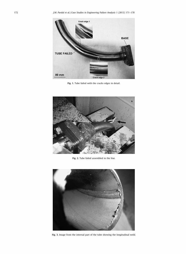
Fig. 1. Tube failed with the cracks edges in detail.
Fig. 2. Tube failed assembled in the line.
Fig. 3. Image from the internal part of the tube showing the longitudinal weld.
J.M. Pardal et al. / Case Studies in Engineering Failure Analysis 1 (2013) 171–178172
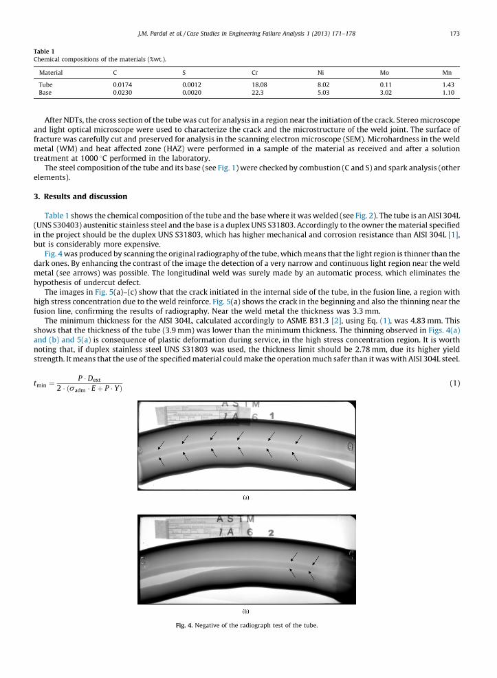
Table 1
Chemical compositions of the materials (%wt.).
Material C S Cr Ni Mo Mn
Tube 0.0174 0.0012 18.08 8.02 0.11 1.43
Base 0.0230 0.0020 22.3 5.03 3.02 1.10
J.M. Pardal et al. / Case Studies in Engineering Failure Analysis 1 (2013) 171–178 173
After NDTs, the cross section of the tube was cut for analysis in a region near the initiation of the crack. Stereo microscopeand light optical microscope were used to characterize the crack and the microstructure of the weld joint. The surface offracture was carefully cut and preserved for analysis in the scanning electron microscope (SEM). Microhardness in the weldmetal (WM) and heat affected zone (HAZ) were performed in a sample of the material as received and after a solutiontreatment at 1000 8C performed in the laboratory.
The steel composition of the tube and its base (see Fig. 1) were checked by combustion (C and S) and spark analysis (otherelements).
3. Results and discussion
Table 1 shows the chemical composition of the tube and the base where it was welded (see Fig. 2). The tube is an AISI 304L(UNS S30403) austenitic stainless steel and the base is a duplex UNS S31803. Accordingly to the owner the material specifiedin the project should be the duplex UNS S31803, which has higher mechanical and corrosion resistance than AISI 304L [1],but is considerably more expensive.
Fig. 4 was produced by scanning the original radiography of the tube, which means that the light region is thinner than thedark ones. By enhancing the contrast of the image the detection of a very narrow and continuous light region near the weldmetal (see arrows) was possible. The longitudinal weld was surely made by an automatic process, which eliminates thehypothesis of undercut defect.
The images in Fig. 5(a)–(c) show that the crack initiated in the internal side of the tube, in the fusion line, a region withhigh stress concentration due to the weld reinforce. Fig. 5(a) shows the crack in the beginning and also the thinning near thefusion line, confirming the results of radiography. Near the weld metal the thickness was 3.3 mm.
The minimum thickness for the AISI 304L, calculated accordingly to ASME B31.3 [2], using Eq. (1), was 4.83 mm. Thisshows that the thickness of the tube (3.9 mm) was lower than the minimum thickness. The thinning observed in Figs. 4(a)and (b) and 5(a) is consequence of plastic deformation during service, in the high stress concentration region. It is worthnoting that, if duplex stainless steel UNS S31803 was used, the thickness limit should be 2.78 mm, due its higher yieldstrength. It means that the use of the specified material could make the operation much safer than it was with AISI 304L steel.
tmin ¼P � Dext
2 � ðsadm � E þ P � YÞ (1)
Fig. 4. Negative of the radiograph test of the tube.
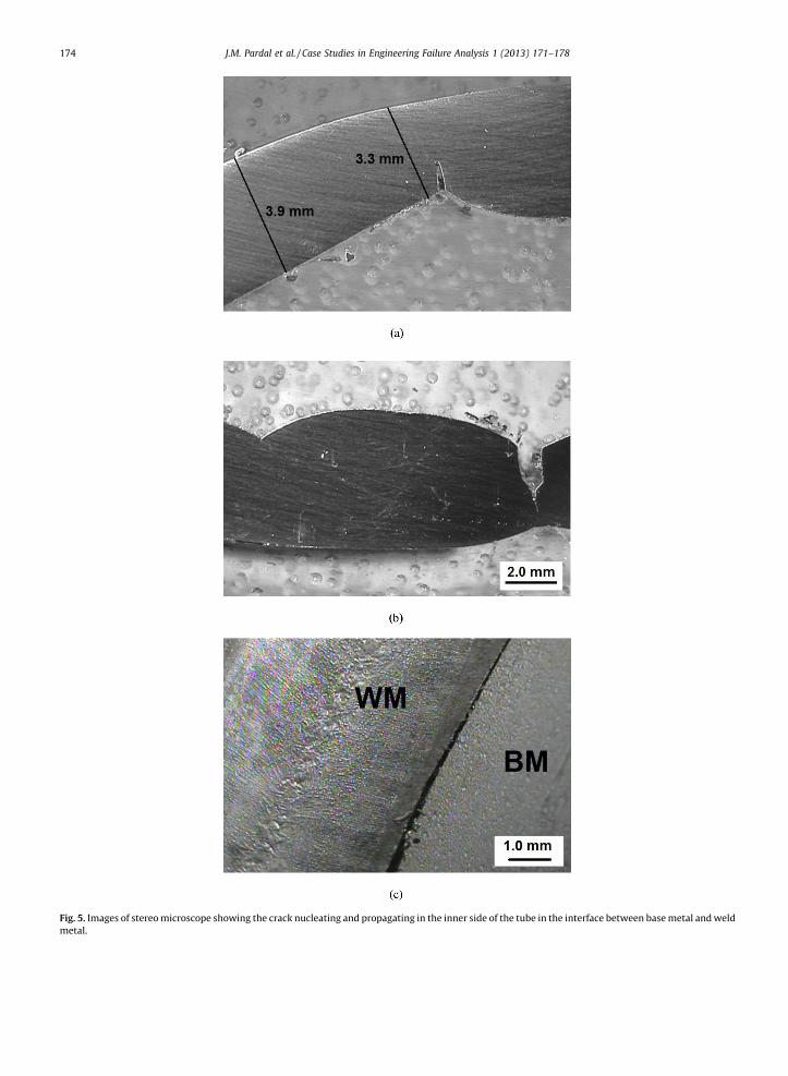
Fig. 5. Images of stereo microscope showing the crack nucleating and propagating in the inner side of the tube in the interface between base metal and weld
metal.
J.M. Pardal et al. / Case Studies in Engineering Failure Analysis 1 (2013) 171–178174
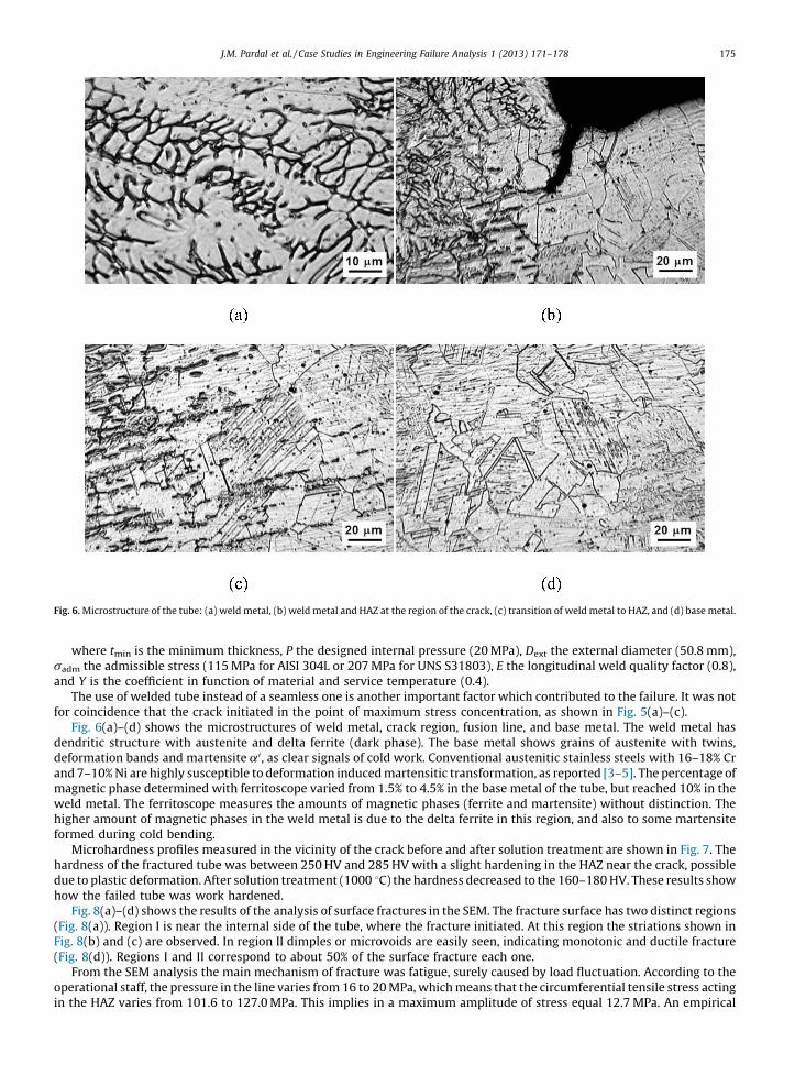
Fig. 6. Microstructure of the tube: (a) weld metal, (b) weld metal and HAZ at the region of the crack, (c) transition of weld metal to HAZ, and (d) base metal.
J.M. Pardal et al. / Case Studies in Engineering Failure Analysis 1 (2013) 171–178 175
where tmin is the minimum thickness, P the designed internal pressure (20 MPa), Dext the external diameter (50.8 mm),sadm the admissible stress (115 MPa for AISI 304L or 207 MPa for UNS S31803), E the longitudinal weld quality factor (0.8),and Y is the coefficient in function of material and service temperature (0.4).
The use of welded tube instead of a seamless one is another important factor which contributed to the failure. It was notfor coincidence that the crack initiated in the point of maximum stress concentration, as shown in Fig. 5(a)–(c).
Fig. 6(a)–(d) shows the microstructures of weld metal, crack region, fusion line, and base metal. The weld metal hasdendritic structure with austenite and delta ferrite (dark phase). The base metal shows grains of austenite with twins,deformation bands and martensite a0, as clear signals of cold work. Conventional austenitic stainless steels with 16–18% Crand 7–10% Ni are highly susceptible to deformation induced martensitic transformation, as reported [3–5]. The percentage ofmagnetic phase determined with ferritoscope varied from 1.5% to 4.5% in the base metal of the tube, but reached 10% in theweld metal. The ferritoscope measures the amounts of magnetic phases (ferrite and martensite) without distinction. Thehigher amount of magnetic phases in the weld metal is due to the delta ferrite in this region, and also to some martensiteformed during cold bending.
Microhardness profiles measured in the vicinity of the crack before and after solution treatment are shown in Fig. 7. Thehardness of the fractured tube was between 250 HV and 285 HV with a slight hardening in the HAZ near the crack, possibledue to plastic deformation. After solution treatment (1000 8C) the hardness decreased to the 160–180 HV. These results showhow the failed tube was work hardened.
Fig. 8(a)–(d) shows the results of the analysis of surface fractures in the SEM. The fracture surface has two distinct regions(Fig. 8(a)). Region I is near the internal side of the tube, where the fracture initiated. At this region the striations shown inFig. 8(b) and (c) are observed. In region II dimples or microvoids are easily seen, indicating monotonic and ductile fracture(Fig. 8(d)). Regions I and II correspond to about 50% of the surface fracture each one.
From the SEM analysis the main mechanism of fracture was fatigue, surely caused by load fluctuation. According to theoperational staff, the pressure in the line varies from 16 to 20 MPa, which means that the circumferential tensile stress actingin the HAZ varies from 101.6 to 127.0 MPa. This implies in a maximum amplitude of stress equal 12.7 MPa. An empirical
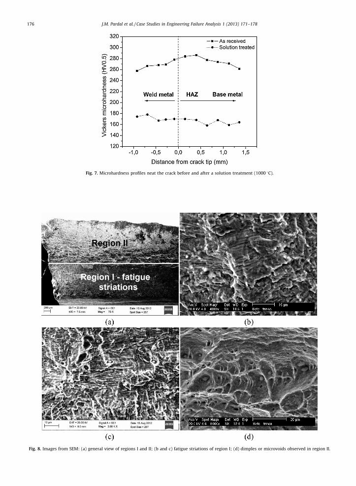
Fig. 7. Microhardness profiles neat the crack before and after a solution treatment (1000 8C).
Fig. 8. Images from SEM: (a) general view of regions I and II; (b and c) fatigue striations of region I; (d) dimples or microvoids observed in region II.
J.M. Pardal et al. / Case Studies in Engineering Failure Analysis 1 (2013) 171–178176
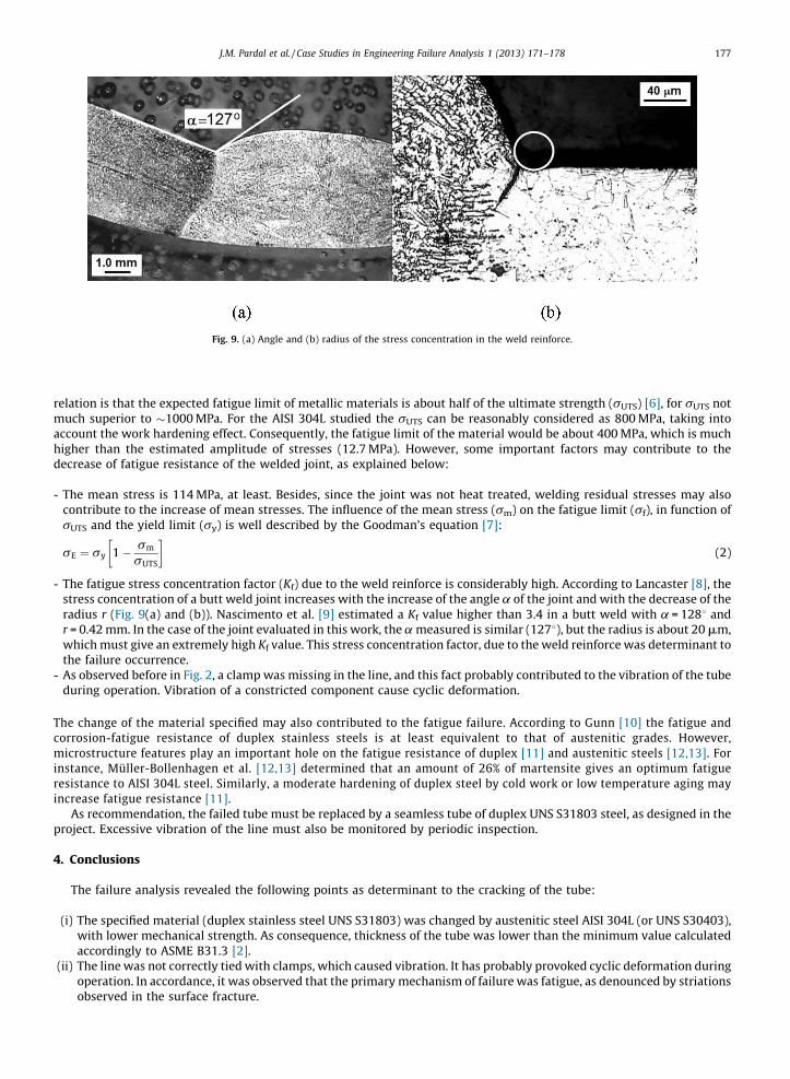
Fig. 9. (a) Angle and (b) radius of the stress concentration in the weld reinforce.
J.M. Pardal et al. / Case Studies in Engineering Failure Analysis 1 (2013) 171–178 177
relation is that the expected fatigue limit of metallic materials is about half of the ultimate strength (sUTS) [6], for sUTS notmuch superior to �1000 MPa. For the AISI 304L studied the sUTS can be reasonably considered as 800 MPa, taking intoaccount the work hardening effect. Consequently, the fatigue limit of the material would be about 400 MPa, which is muchhigher than the estimated amplitude of stresses (12.7 MPa). However, some important factors may contribute to thedecrease of fatigue resistance of the welded joint, as explained below:
- T
he mean stress is 114 MPa, at least. Besides, since the joint was not heat treated, welding residual stresses may alsocontribute to the increase of mean stresses. The influence of the mean stress (sm) on the fatigue limit (sf), in function ofsUTS and the yield limit (sy) is well described by the Goodman’s equation [7]:sE ¼ sy 1 � sm
sUTS
� �(2)
The fatigue stress concentration factor (Kf) due to the weld reinforce is considerably high. According to Lancaster [8], the
- stress concentration of a butt weld joint increases with the increase of the angle a of the joint and with the decrease of theradius r (Fig. 9(a) and (b)). Nascimento et al. [9] estimated a Kf value higher than 3.4 in a butt weld with a = 1288 andr = 0.42 mm. In the case of the joint evaluated in this work, the a measured is similar (1278), but the radius is about 20 mm,which must give an extremely high Kf value. This stress concentration factor, due to the weld reinforce was determinant tothe failure occurrence.- A
s observed before in Fig. 2, a clamp was missing in the line, and this fact probably contributed to the vibration of the tubeduring operation. Vibration of a constricted component cause cyclic deformation.The change of the material specified may also contributed to the fatigue failure. According to Gunn [10] the fatigue andcorrosion-fatigue resistance of duplex stainless steels is at least equivalent to that of austenitic grades. However,microstructure features play an important hole on the fatigue resistance of duplex [11] and austenitic steels [12,13]. Forinstance, Muller-Bollenhagen et al. [12,13] determined that an amount of 26% of martensite gives an optimum fatigueresistance to AISI 304L steel. Similarly, a moderate hardening of duplex steel by cold work or low temperature aging mayincrease fatigue resistance [11].
As recommendation, the failed tube must be replaced by a seamless tube of duplex UNS S31803 steel, as designed in theproject. Excessive vibration of the line must also be monitored by periodic inspection.
4. Conclusions
The failure analysis revealed the following points as determinant to the cracking of the tube:
(i) T
he specified material (duplex stainless steel UNS S31803) was changed by austenitic steel AISI 304L (or UNS S30403),with lower mechanical strength. As consequence, thickness of the tube was lower than the minimum value calculatedaccordingly to ASME B31.3 [2].(ii) T
he line was not correctly tied with clamps, which caused vibration. It has probably provoked cyclic deformation duringoperation. In accordance, it was observed that the primary mechanism of failure was fatigue, as denounced by striationsobserved in the surface fracture.
J.M. Pardal et al. / Case Studies in Engineering Failure Analysis 1 (2013) 171–178178
(iii) T
he use of a welded tube with internal reinforce, instead of a seamless one, caused strong stress concentration. Thefatigue crack initiated and propagated through this region.References
[1] Voronenko BI. Austenitic–ferritic stainless steels: a state-of-the-art review. Metal Science and Heat Treatment 2010;39(9/10):428–37.[2] ASME B31.3: process piping. 2000 Addenda, American Society of Mechanical Engineers; 1999.[3] da Rocha MR, de Oliveira CAS. Evaluation of the martensitic transformations in austenitic stainless steels. Materials Science and Engineering A
2009;517(1/2):281–5.[4] Nagy E, Mertinger V, Tranta F, Solvom J. Deformation induced martensitic transformation in stainless steels. Materials Science and Engineering A
2004;378(1/2):308–13.[5] Zinbi A, Bouchou A. Delayed cracking in 301 austenitic steel after bending process: martensitic transformation and hydrogen embrittlement analysis.
Engineering Failure Analysis 2010;17(5):1028–37.[6] Jaske CE, Payer JH, Bellint VS. Corrosion fatigue properties of metals in marine environments. Inco Publication; 1977.[7] Dieter GE. Mechanical metallurgy. UK: McGraw Hill; 1988.[8] Lancaster JF. Metallurgy of welding. 6th ed. England: Abington Publishing; 1999.[9] Nascimento MP, Voorwald HJC, Filho JCP. Fatigue strenght of tungsten inert gas-repaired weld joints in airplane critical structures. Journal of Materiais
Processing Technology 2011;211(6):1126–35.[10] Gunn RN. Duplex stainless steels, microstructures, properties and applications. Abington Publishing; 1997.[11] Lanes L, Mateo A, Violan P, Mendez J, Anglada M. On the high cycle fatigue behavior of duplex stainless steels: influence of thermal aging. Materials
Science and Engineering A 1997;234–236:850–2.[12] Muller-Bollenhagen C, Zimmermann M, Christ HJ. Very high cycle fatigue behavior of austenitic stainless steels and the effect of strain-induced
martensite. International Journal of Fatigue 2010;32:936–42.[13] Muller-Bollenhagen C, Zimmermann M, Christ HJ. Adjusting the very high cycle fatigue properties of a metastable austenitic stainless steel by means of
the martensite content. Procedia Engineering 2010;2:1663–72.