Embed Size (px)
Citation preview
AD
TECHNICAL REPORT ARCCB-TR-03005
FATIGUE AND HYDROGEN CRACKING IN CANNONS WITH MECHANICAL AND
THERMAL RESIDUAL STRESSES
J. H. UNDERWOOD A. P. PARKER
E. TROIANO G. N. VIGILANTE
M. D. WITHERELL
APRIL 2003
US ARMY ARMAMENT RESEARCH, DEVELOPMENT AND ENGINEERING CENTER ^ ^
Close Combat Armaments Center rlUBJmjM) Benet Laboratories
Watervllet. NY 12189-4000 TAOOK-AROEO
APPROVED FOR PUBLIC RELEASE; DISTRIBUTION UNLIMITED
20030527 126
DISCLAIMER
The findings in this report are not to be construed as an official Department of the
Army position unless so designated by other authorized documents.
The use of trade name(s) and/or manufacturer(s) does not constitute an official
endorsement or approval.
DESTRUCTION NOTICE
For classified documents, follow the procedures in DoD 5200.22-M, Industrial
Security Manual, Section 11-19, or DoD 5200.1-R, Information Security Program
Regulation, Chapter IX.
For unclassified, limited documents, destroy by any method that will prevent
disclosure of contents or reconstruction of the document.
For unclassified, unlimited documents, destroy when the report is no longer
needed. Do not return it to the originator.
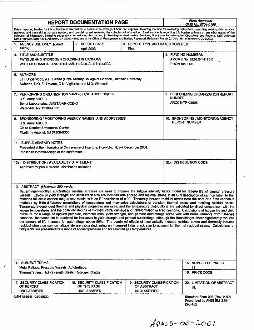
REPORT DOCUMENTATION PAGE Form Approved OMB No. 0704-018B
Public reporting burden for this collection of information is estimated to average 1 iKiur per response, including the time for reviewing instructions, searching existing data sources, gathering and maintaining the data needed, and completing and reviewing the collection of information. Send comments regarding this burden estimate or any other aspect of this collection of information, including suggestions for reducing this burden, to Washington Headquarters Sen/ices, Directorate Ibr infomnation Operations and Reports, 1215 Jefferson Davis Highway, Suite 1204, Arlington, VA 22202-4302, and to the Office of Management and Budget, Paperwarl( Reduction Project (0704-0188), Washington, DC 20503.
1. AGENCY USE ONLY (Leave Blar)k)
REPORT DATE April 2003
3. REPORT TYPE AND DATES COVERED Final
TITLE AND SUBTITLE FATIGUE AND HYDROGEN CRACKING IN CANNONS WITH MECHANICAL AND THERMAL RESIDUAL STRESSES
6. AUTHORS J.H. Underwood, A.P. Paricer (Royal Military College of Science, Cranfield University, Swindon, UK), E. Trolano, G.N. Vigilante, and M.D. Witherell
5. FUNDING NUMBERS AMCMS No. 6226.24.H180.0 PRON No. TU2
7. PERFORMING ORGANIZATION NAME(S) AND ADDRESS(ES) U.S. Army ARDEC Benet Laboratories, AMSTA-AR-CCB-O Watervliet, NY 12189-4000
8. PERFORMING ORGANIZATION REPORT NUMBER ARCCB-TR-03005
9. SPONSORING / MONITORING AGENCY NAME(S) AND ADDRESS(ES) U.S. Army ARDEC Close Combat Annaments Center Picatinny Arsenal, NJ 07806-5000
10. SPONSORING / MONITORING AGENCY REPORT NUMBER
11. SUPPLEMENTARY NOTES Presented at ttie International Conference of Fracture, Honolulu, HI, 3-7 December 2001. Published in proceedings of the conference.
12a. DISTRIBUTION / AVAILABILITY STATEMENT Approved for public release; distribution unlimited.
12b. DISTRIBUTION CODE
13. ABSTRACT (Maximum 200 words) Bauschinger-modified autofrettage residual stresses are used to improve the Mtigue Intensity factor model for fatigue life of cannon pressure vessels. Effects of yield strength and initial crack size are included with applied and residual stress In an S-N description of cannon tube life that matches full-scale cannon fatigue test results with an R^ correlation of 0.92. Thermally induced residual stress near the bore of a fired cannon is modeled by finite-difference calculations of temperature and mechanics calculations of transient thennal stress and resulting residual stress. Temperature-dependent thermal and physical properties are used, and the temperature distributions are validated by direct comparison with the known temperatures and the observed depths of microstructural damage and transformation in fired cannons. Calculations of fatigue life and yield pressure for a range of applied pressure, diameter ratio, yield strength, and percent autofrettage agree well with measurements from full-scale cannons. Increased life Is predicted for increases in yield strength and percent autofrettage, although ttie Bauschinger effect significantiy reduces the amount of life Increase for autofrettage above 50%. The combined effects of mechanically induced residual stress and thermally Induced residual stress on cannon fatigue life are calculated, using an Increased initial crack size to account for thermal residual stress. Calculations of fatigue life are presented for a range of applied pressure and for selected gas temperatures.
14. SUBJECT TERMS Metal Fatigue, Pressure Vessels, Autofrettage, Thermal Stress, High-Strengtti Steels, Hydrogen Cracks
15. NUMBER OF PAGES 11
16. PRICE CODE
17. SECURITY CLASSIFICATION OF REPORT UNCLASSIFIED
18. SECURITY CLASSIFICATION OF THIS PAGE UNCLASSIFIED
19. SECURITY CLASSIFICATION OF ABSTRACT UNCLASSIFIED
20. LIMITATION OF ABSTRACT UL
NSN 7540-01-280-5500 Standard Form 298 (Rev. 2-89) Prescribed by ANSI Std. Z39-1 298-102
J'Q/{6 3~Or^-2a€ I
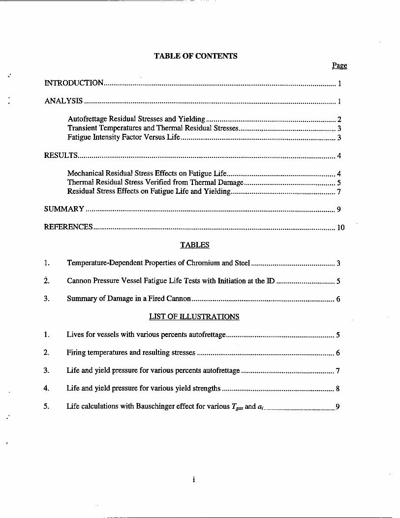
TABLE OF CONTENTS Page
INTRODUCTION 1
ANALYSIS 1
Autofrettage Residual Stresses and Yielding 2 Transient Temperatures and Thermal Residual Stresses , 3 Fatigue Intensity Factor Versus Life 3
RESULTS 4
Mechanical Residual Stress Effects on Fatigue Life 4 Thermal Residual Stress Verified from Thermal Damage 5 Residual Stress Effects on Fatigue Life and Yielding 7
SUMMARY 9
REFERENCES 10
TABLES
1. Temperature-Dependent Properties of Chromium and Steel 3
2. Cannon Pressure Vessel Fatigue Life Tests with Initiation at the ID 5
3. Summary of Damage in a Fired Cannon 6
LIST OF ILLUSTRATIONS
1. Lives for vessels with various percents autofrettage 5
2. Firing temperatures and resulting stresses 6
3. Life and yield pressure for various percents autofrettage , 7
4. Life and yield pressure for various yield strengths 8
5. Life calculations with Bauschinger effect for various Tga, and a, 9
INTRODUCTION
The benefit of mechanically induced autofrettage residual stress in extending the fatigue life of a pressure vessel has been known for decades. Only relatively recently has comprehensive predictive analysis of autofrettage residual stress been available that can account for the actual material properties of pressure vessel steels, most importantly the significant reduction of compressive yield strength that occurs in an autofrettaged vessel, known as the Bauschinger effect. Measurements of the Bauschinger effect in the Nickel-Chromium- Molybdenum (Ni-Cr-Mo) steels commonly used in cannon pressure vessels have long been available (ref 1). Analysis of the Bauschinger strength reductions that are observed for different vessel diameter ratios and degrees of autofrettage was described by Chaaban et al. (ref 2), but they used a simple bilinear representation of the reduced compressive yielding, whereas a much more complex nonUnear behavior is observed. Parker (ref 3) has provided useful expressions that will be used here to calculate autofrettage residual stresses at the bore of pressure vessels with Ni-Cr-Mo-type Bauschinger properties, accounting for diameter ratio, degree of autofrettage, and nonlinear behavior, the effects of concern here.
In the past decade, a troublesome type of thermally induced residual stress has been found to affect cracking and service life of cannon pressure vessels. Underwood et al. (ref 4) showed metallographic evidence of a constant-depth array of cracks at the inner surface of fired cannon tubes that cannot be explained by a mechanical fatigue process. Finite-difference calculations of the transient temperatures at the inner surface of a fired cannon tube predicted yield-level transient compressive stresses to about the same depth as the crack array, suggesting that tensile residual stress was present to this depth. Given that significant hydrogen is produced in cannon firing and cannon steels are highly susceptible to hydrogen cracking, the constant- depth cracks can be explained as hydrogen cracks. In the work here, additional finite-difference temperature calculations and transient and residual stress calculations are performed to determine the effect of thermally induced residual stresses and cracking on fatigue life of cannon pressure vessels. The fatigue life implications of both the mechanically induced autofrettage residual stresses and the thermally induced firing residual stresses will be described in the work here using the fatigue intensity factor (FIF) concept developed by Underwood and Parker (ref 5). This modified S-N approach gives a high-correlation, single-expression description of fatigue life for a wide range of vessel configuration, stress concentration, applied and residual stresses, yield strength, and initial crack size.
ANALYSIS
The residual stresses in a cannon pressure vessel that will be discussed here are those produced by a mechanical mandrel-swage autofrettage process during fabrication of the cannon tube and those produced by the transient convective heating of the inner diameter (ID) of the tube during cannon firing. Transient heating of a cannon ID during firing has traditionally been important only because it would initiate fatigue cracking somewhat earlier than would otherwise be expected. However, with increases in cannon firing pressures, temperatures, and duration, ID thermal damage is deeper and asserts a more significant control over cannon fatigue life than in the past. The finite-difference method is used to calculate the near-ID transient temperature distribution, as the initial measure of the degree and depth of thermal damage. The temperatures
1
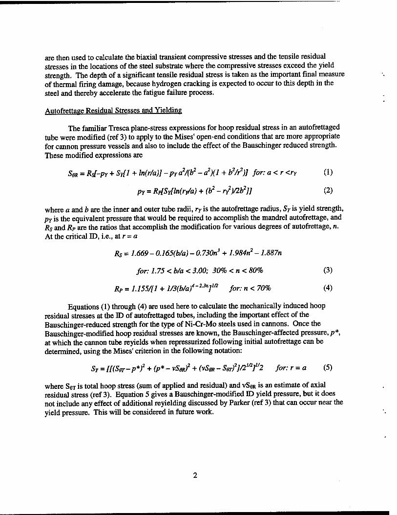
are then used to calculate the biaxial transient compressive stresses and the tensile residual stresses in the locations of the steel substrate where the compressive stresses exceed the yield strength. The depth of a significant tensile residual stress is taken as the important final measure of thermal firing damage, because hydrogen cracking is expected to occur to this depth in the steel and thereby accelerate the fatigue failure process.
Autofrettage Residual Stresses and Yielding
The familiar Tresca plane-stress expressions for hoop residual stress in an autofrettaged tube were modified (ref 3) to apply to the Mises' open-end conditions that are more appropriate for cannon pressure vessels and also to include the effect of the Bauschinger reduced strength. These modified expressions are
SoR = Rs[-PY + SY[1 + ln(r/a)]-pra^/{h^-c^){l + h^/r^)] for:aKrKry (1)
PY = Rp[SY[ln(ry/a) + (b^-rY^)/2b^]] (2)
where a and b are the inner and outer tube radii, ry is the autofrettage radius, Sy is yield strength, PY is tiie equivalent pressure that would be required to accomplish the mandrel autofrettage, and Rs and Rp are the ratios that accomplish the modification for various degrees of autofrettage, n. At the critical E), i.e., atr = a
Rs = 1.669 - 0.165(b/a) - 0.730n^ + 1.984n^ - 1.887n
for: 1.75< b/a <3.00; 30% <n< 80% (3)
Rp = l. 155/11 + l/3(b/af - ^■^"7^'^ for: n < 70% (4)
Equations (1) through (4) are used here to calculate the mechanically induced hoop residual stresses at the ID of autofrettaged tubes, including the important effect of the Bauschinger-reduced strength for the type of Ni-Cr-Mo steels used m cannons. Once the Bauschinger-modified hoop residual stresses are known, the Bauschinger-affected pressure, p*, at which the cannon tube reyields when repressurized following initial autofrettage can be determined, using the Mises' criterion in the following notation:
SY = [[(Sffr-p*f + (p*-vSgRf + (vSgR-Serf]/2^^f2 for:r = a (5)
where Sei is total hoop stress (sum of applied and residual) and VSOR is an estimate of axial residual stress (ref 3). Equation 5 gives a Bauschinger-modified ID yield pressure, but it does not include any effect of additional reyielding discussed by Parker (ref 3) that can occur near the yield pressure. This will be considered in future work.
Transient Temperatures and Thermal Residual Stresses
Finite-difference calculations of one-dimensional convective heat flow were used to determine the near-ID temperatures produced by cannon firing conditions. The calculations used increments of 0.02-mm in depth below the heated bore surface. About fifty increments were required for the temperature to drop from typically 1500°K at the surface to within 1°K of ambient (300°K) at about 1-mm below the surface, for the few ms of convective heating typical of cannon firing. Temperature-dependent material properties (refs 6-8) of the 0.1-mm thick electroplated chromium bore coating and the Ni-Cr-Mo steel substrate were used for the analysis, in the form d(T) = Co + CjT, with values of Co and Ci as in Table 1. The inputs to the finite- difference calculations, in addition to the chromium and steel properties, were:
• The initial ambient temperature, J,, 300°K • The duration of the convective heating pulse at the tube surface, 0.008-s • The convection coefficient, h, of the heating pulse, 193,000 W/m^°K • The mean gas temperature of the pulse, with values as discussed in the upcoming
results
Table 1. Temperature-Dependent Properties of Chromium and Steel
Property Units Range (°K)
Chromium Co Ci
Ni-Cr-Mo Steel Co Ci
Thermal Diffusivity, S m^/s 300-2000 29.6E-6 -12.6E-9 njE-6 -53E-9 Thermal Conductivity, k W/m°K 300-2000 97.2 -0.0266 43.6 -0.0097 Elastic Modulus, E GPa 300-1000 248 -0.0968 Thermal Expansion, a 1/°K 300-1000 13.5E-6 0 Yield Strength, Sy MPa 300-1000 1740 -1.62
Expressions for the near-bore, transient, in-plane, biaxial compressive thermal stress, ST, and the tensile residual stress, SR, produced when the transient stress exceeds the material yield strength are
ST = -Ea[Tfx,t}-TiJ/[l-v] (6)
where v is Poisson's ratio; the transient temperature, T, is for a given depth, x, below the bore surface and time, t, after the start of a heating pulse; the term [1 - v] accounts for the biaxial nature of the temperature and stress distributions. Then SR is determined directly using the linear unloading concept, SR = -Sr-Sy.
Fatigue Intensitv Factor Versus Life
The effects of autofrettage and thermal residual stresses on fatigue life will be described in the work here using the FIF concept (ref 5). In brief summary, the FIF concept adds a quantitative measure of material yield strength and initial crack size to the stress parameter in a log-stress versus log-life description of fatigue life behavior of a structure. By adding material strength and initial crack size to S-N life descriptions, significant improvements in life modeling
3
of cannon pressure vessels have been shown. The key expressions for an FIF description of ID- initiated fatigue life of a pressurized, autofrettaged cannon pressure vessel are
FIF = ASwcAL X(SY.NOM/SY) xiai/aLmmf^ (7)
ASwCAL = ktSAPPUED + SRESIDUAL + P (8)
Note that the local stress range for ID-initiated cracking includes:
• The familiar Lam6-applied ID stress for the appropriate p and b/a, with stress concentration factor, k,, if one is present
• The ID hoop residual stress, accounting for the Bauschinger-reduced strength, using equations (1) through (4), but no fc,even if present because it would be negated by the Bauschinger effect
• An added stress equal in magnitude to p, to account for the effects of pressure on the crack faces (ref 5)
The second term in equation (7) accounts for the yield strength of a given vessel when different from the nominal yield strength of the vessels under comparison. The third term accounts for the initial crack size of a given vessel if different from the nominal initial crack size of the vessels under comparison. As will be seen in the forthcoming results, the effect of thermally induced tensile residual stresses in cannon vessels can be accounted for by using a, values associated with the depth of the tensile residual stresses in cannons critically subject to hydrogen cracking.
RESULTS
Mechanical Residual Stress Effects on Fatigue Life
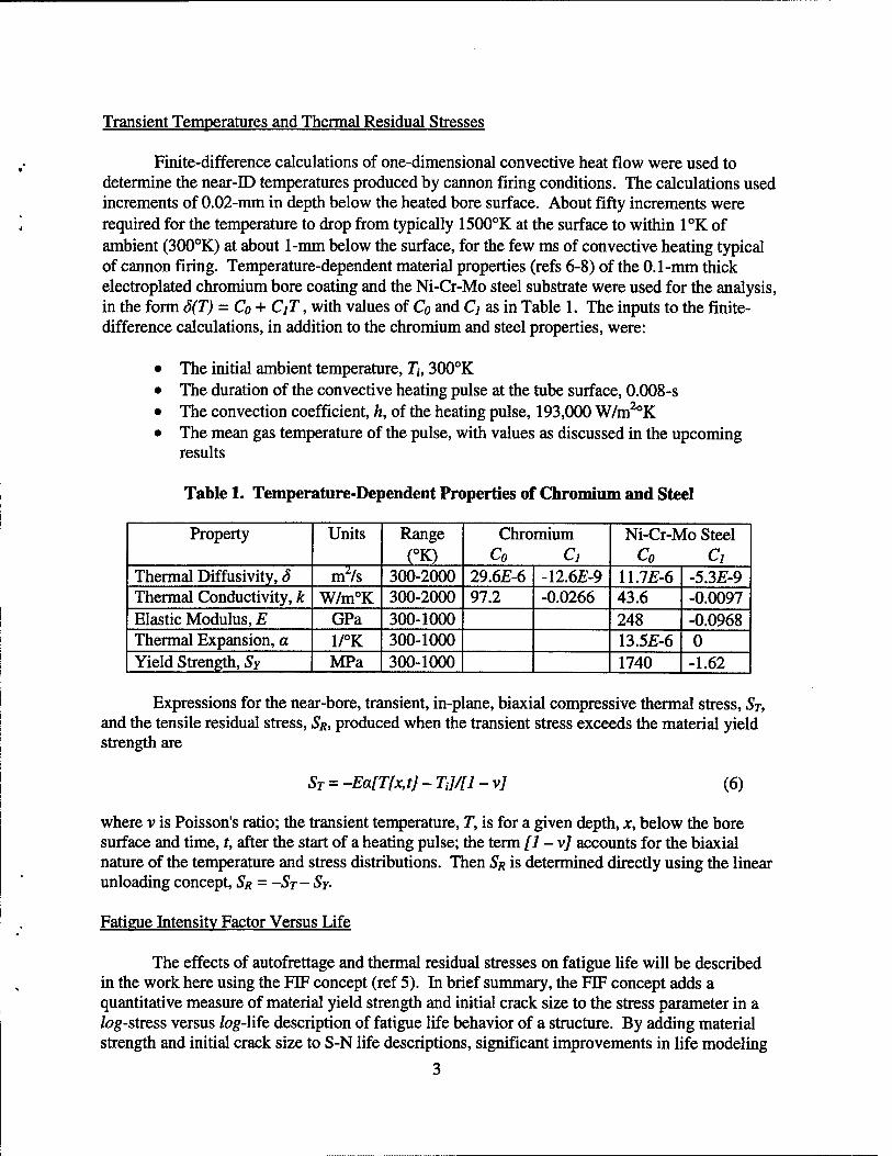
A baseline description of the effect of mechanical autofrettage residual stresses on ID- initiated fatigue life for cannon tubes is available from prior results of full-scale cannon fatigue tests (ref 5). Four groups of the prior fatigue tests that were ID-initiated and had well documented initial crack sizes will be used for a baseline fatigue life; see Table 2. Two of the groups were rifled caimons, with a k, of 1.7 to account for the radius between the rifling land and groove. The measured fatigue lives of the sixteen tests from these four groups are shown in Figure 1, using FIF as the stress parameter in the S-N plot. Referring again to equations (7) and (8), FIF was calculated using each of the sixteen values of Sy, SY-NOM =1134 MPa, ai.NOM = 0.10- mm, and values from Table 2. The high correlation of the linear regression expression shows that an FIF-based S-N plot gives a good description of fatigue life for cannons, including the significant effect of autofrettage residual stress.
Table 2. Cannon Pressure Vessel Fatigue Life Tests with Initiation at the ID
Group Mean Yield Strength
(SY. MPa)
Inner Radius (a, mm)
Outer Radius (b,mm)
Initial Crack
(fl„ nrni)
Stress Concentration
(k.)
Fatigue Pressure (p,MPa)
Degree of Autofrettage
(n, %) 75N 1280 89 187 0.01 1.7 345 0 75A 1020 89 187 0.01 1.7 345 50 55 1230 89 142 0.10 1.0 393 60 20 1120 79 155 0.10 1.0 670 60
10,000 MPa
1.000:
100
♦ - 75A; 50% swage ■ • 7$N; 0% swage A - 55; 60% swage # . 20; «>% swage
N-1.97x10*/ FIF^^
l^"0.92
1.000 I t I I I I I
10,000 -I—I—I III'
100,0(K>
fytigu0Nfe,N; cycles
Figure 1. Lives for vessels with various percents autofrettage.
Thermal Residual Stress Verified from Thermal Damage
Inputs to finite-difference calculations of near-bore cannon temperatures are, inevitably, somewhat uncertain. So, before the calculated temperatures are used to determine residual stress, they should be verified by metallographic observations of thermal damage. This has been done for a cannon after the firing of about 40 high-temperature rounds (ref 4); see Table 3. About two-thirds of the 0.12-mm thickness of chromium showed a transformed microstructure associated with a temperature of about 1320°K. A more certain validation point is the well- known 1020°K phase transformation for this type of low-alloy Ni-Cr-Mo cannon steel, with metallographs showing a consistent, clear depth of 0.19-mm. One further dominant damage feature observed was an ever-present array of constant-depth cracks normal to the longitudinal orientation of the cannon, an orientation known to have no significant applied tensile stress. As discussed next, the crack array provides added verification of the calculated depth of thermally induced residual stress due to cannon firing.
Table 3. Simunary of Damage in a Fired Cannon
Thickness of Chromium Layer
(mm)
Depth of Chromium Damage Layer
(mm)
Depth of Steel Transformation
(mm)
Depth of Crack Array; Longitudinal Section
(mm) 0.12 0.08 0.19 0.46
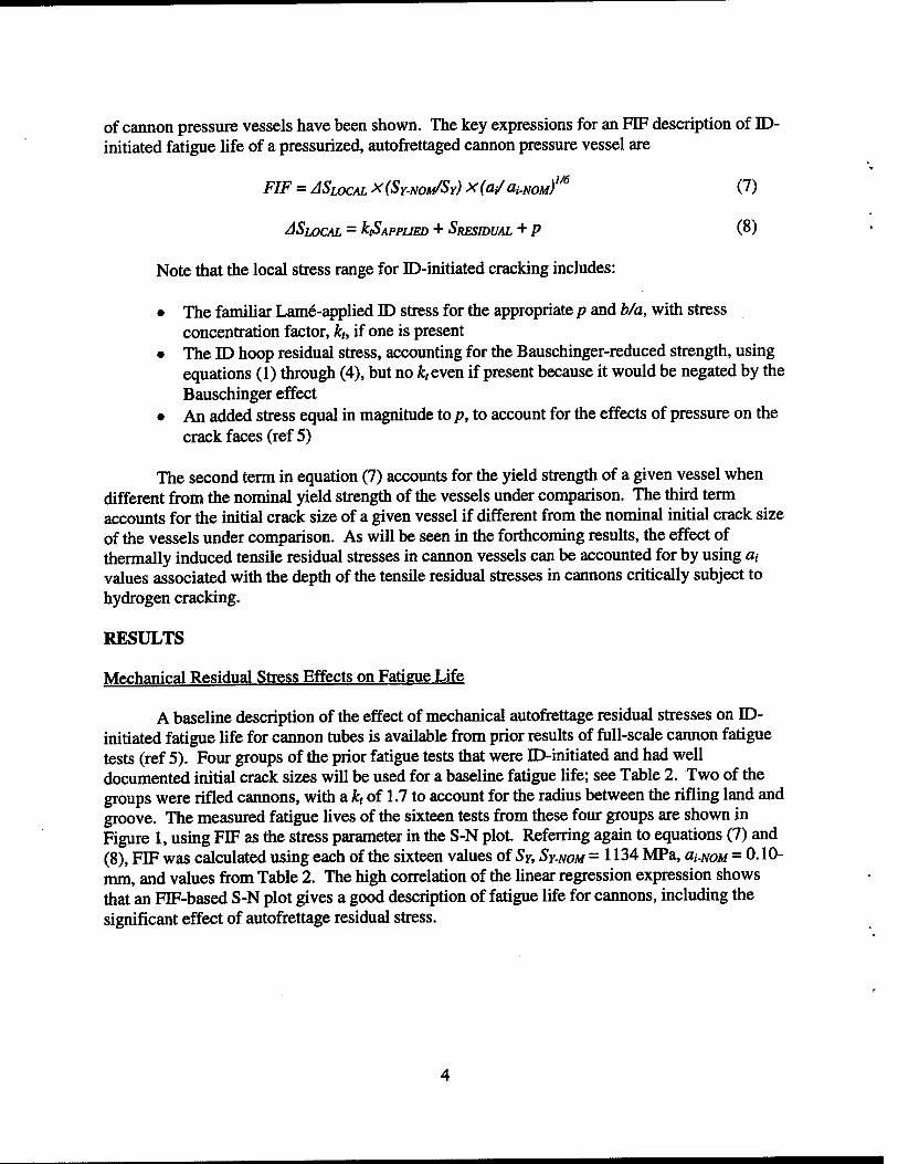
Results of finite-difference calculations of temperatures and solid mechanics calculations of transient and residual stresses, using the methods and validation already discussed, are shown in Figure 2. The solid line shows the calculated maximum temperatures versus distance below the bore surface for the following input values:
• The d and k properties for chromium and steel from Table 1 • Tgas = 2\60°K and 0.008-s pulse duration
2oi • /i= 193,000 W/m^°K
2000
• -obMivKidvptiwof tninsfbmurtlon
compraMiw tnuttitntttrass
0.1 0.2 0.3 0.4
tUstanco Mow bon surface, x; mm
Figure 2. Firing temperatures and resulting stresses.
Note that the depths and temperatures of the 1320 and 1020°K transformations of chromium and steel are well matched for the calculated temperamre distribution, so it should be a useful basis for transient and residual stress calculations. These stress calculations are shown in Figure 2 for selected ranges of depth somewhat below the bore surface; calculations very near the bore surface have little meaning due to the lack of information on material properties at the temperatures in this region. The significant region of tensile residual stress up to about 0.38-mm below the bore surface is alarming, considering the presence of hydrogen and the susceptibility of high-strength cannon steel to hydrogen cracking.
Residual Stress Effects on Fatigue Life and Yielding
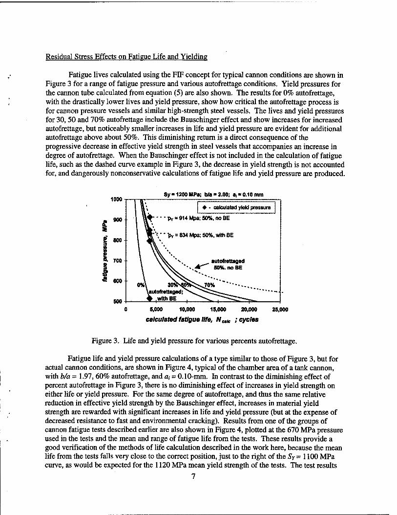
Fatigue lives calculated using the FIF concept for typical cannon conditions are shown in Figure 3 for a range of fatigue pressure and various autofrettage conditions. Yield pressures for the cannon tube calculated from equation (5) are also shown. The results for 0% autofrettage, with the drastically lower lives and yield pressure, show how critical the autofrettage process is for cannon pressure vessels and similar high-strength steel vessels. The lives and yield pressures for 30,50 and 70% autofrettage include the Bauschinger effect and show increases for increased autofrettage, but noticeably smaller increases in life and yield pressure are evident for additional autofrettage above about 50%. This diminishing return is a direct consequence of the progressive decrease in effective yield strength in steel vessels that accompanies an increase in degree of autofrettage. When the Bauschinger effect is not included in the calculation of fatigue life, such as the dashed curve example in Figure 3, the decrease in yield strength is not accounted for, and dangerously nonconservative calculations of fatigue life and yield pressure are produced.
1000
900
Sy'1200MPa; b/a«2.00; ai* 0.10 mm
i f 800- a
2- 700 + I f « 600
500
calculated yield pressure
S,000 10,000 18,000 20,000 25,000
calculated fatigue llfB, Ncie ; cycles
Figure 3. Life and yield pressure for various percents autofrettage.
Fatigue life and yield pressure calculations of a type similar to those of Figure 3, but for actual cannon conditions, are shown in Figure 4, typical of the chamber area of a tank cannon, with b/a = 1.97, 60% autofrettage, and a, = 0.10-mm. In contrast to the diminishing effect of percent autofrettage in Figure 3, there is no diminishing effect of increases in yield strength on either life or yield pressure. For the same degree of autofrettage, and thus the same relative reduction in effective yield strength by the Bauschinger effect, increases in material yield strength are rewarded with significant increases in life and yield pressure (but at the expense of decreased resistance to fast and environmental cracking). Results from one of the groups of cannon fatigue tests described earlier are also shown in Figure 4, plotted at the 670 MPa pressure used in the tests and the mean and range of fatigue life from the tests. These results provide a good verification of the methods of Ufe calculation described in the work here, because the mean life from the tests falls very close to the correct position, just to the right of the Sy = 1100 MPa curve, as would be expected for the 1120 MPa mean yield strength of the tests. The test results
7
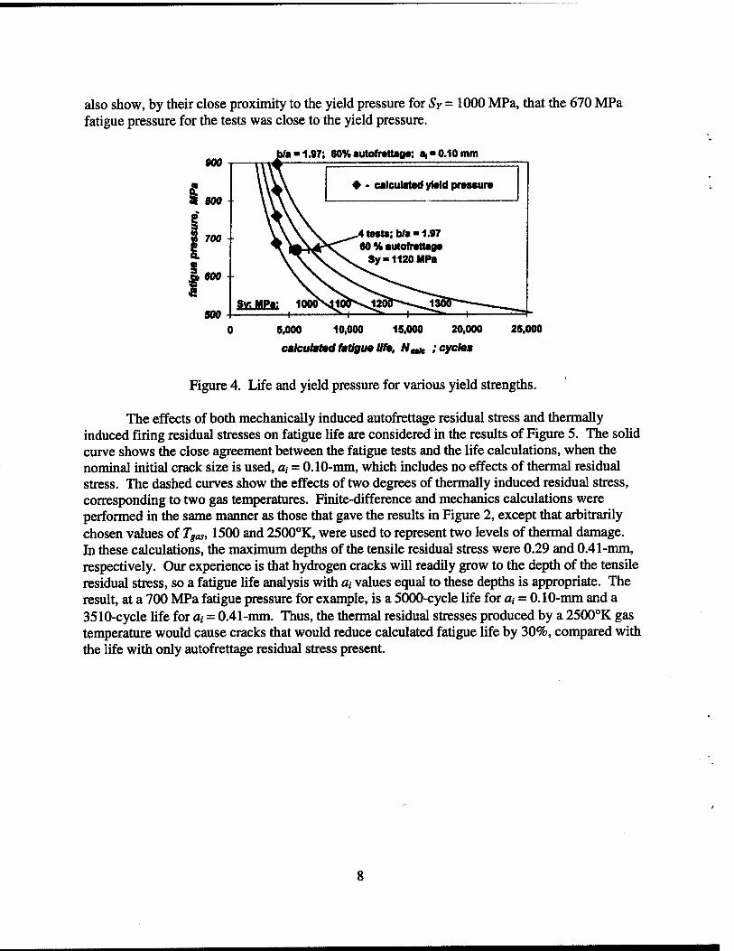
also show, by their close proximity to the yield pressure for Sy = 1000 MPa, that the 670 MPa fatigue pressure for the tests was close to the yield pressure.
b/a">1.97; 60%autofr*ttao«-, at*0.10mm
calculatwi]
9.000 10,000 15.000 20.000
calculdtMl fatlgu0 lift, N,Mt !cyeh»
25.000
Figure 4. Life and yield pressure for various yield strengths.
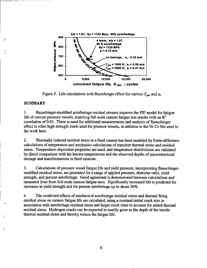
The effects of both mechanically induced autofrettage residual stress and thermally induced firing residual stresses on fatigue life are considered in the results of Figure 5. The solid curve shows the close agreement between the fatigue tests and the life calculations, when the nominal initial crack size is used, a, = 0.10-mm, which includes no effects of thermal residual stress. The dashed curves show the effects of two degrees of tiiermally induced residual stress, corresponding to two gas temperatures. Finite-difference and mechanics calculations were performed in the same manner as those that gave the results in Figure 2, except that arbitrarily chosen values of Tgas, 1500 and 2500°K, were used to represent two levels of thermal damage. In these calculations, the maximum depths of the tensile residual stress were 0.29 and 0.41-mm, respectively. Our experience is that hydrogen cracks will readily grow to the depth of the tensile residual stress, so a fatigue life analysis with a, values equal to these depths is appropriate. The result, at a 700 MPa fatigue pressure for example, is a 5000-cycle life for a, = 0. lO-mm and a 3510-cycle life for at = 0.41-mm. Thus, the thermal residual stresses produced by a 2500°K gas temperature would cause cracks that would reduce calculated fatigue life by 30%, compared with the life with only autofrettage residual stress present.
800 b/a - 1.97; Sy - 1120 Mpa; 60% autofrtttaga
4ta8t8; b/a-1.97 60 % autofrattaga
Sy«1120MPa ai" 0.10 mm
no damaga ; ai • 0.10 mm
T,„ B 1S00 K; ai" 0.29 mm 2500 K: a,« 0.41 mm
5.000 10,000 15,000
calculated fatlguo life, Afcaic ; cycles
20,000
Figure 5. Life calculations with Bauschinger effect for various Tgas and a,.
SUMMARY
1. Bauschinger-modified autofrettage residual stresses improve the FIF model for fatigue life of cannon pressure vessels, matching full-scale cannon fatigue test results with an R^ correlation of 0.92. There is need for additional measurements and analysis of Bauschinger effect in other high-strength steels used for pressure vessels, in addition to the Ni-Cr-Mo steel in the work here.
2. Thermally induced residual stress in a fired cannon has been modeled by finite-difference calculations of temperature and mechanics calculations of transient thermal stress and residual stress. Temperamre-dependent properties are used, and temperature distributions are validated by direct comparison with the known temperatures and the observed depths of microstructural damage and transformations in fired cannons.
3. Calculations of pressure vessel fatigue life and yield pressure, incorporating Bauschinger- modified residual stress, are presented for a range of applied pressure, diameter ratio, yield strength, and percent autofrettage. Good agreement is demonstrated between calculations and measured lives from full-scale carmon fatigue tests. Significantly increased life is predicted for increases in yield strength and for percent autofrettage up to about 50%.
4. The combined effects of mechanical autofrettage residual stress and thermal firing residual stress on cannon fatigue life are calculated, using a nominal initial crack size in association with autofrettage residual stress and larger crack sizes to account for added thermal residual stress. Hydrogen cracks can be expected to readily grow to the depth of the tensile thermal residual stress and thereby reduce the fatigue life.
REFERENCES
1. Milligan, R.V., Koo, W.H., and Davidson, T.E., Transactions of the ASME D, 1966, pp. 480-488.
2. Chaaban, A., Leung, K., and Bums, D.J., (1986) ASME Special Publication, PVP Vol. no, 1986, pp. 55-60.
3. Parker, A.P., Journal of Pressure Vessel Technology, Vol.123,2001, pp. 203-206.
4. Underwood, J.H., Parker, A.P., Cote, P.J., and Sopok, S., Journal of Pressure Vessel Technology, Yoini, 1999, pp. 116-120.
5. Underwood, J.H., and Parker, A.P., Advances in Fracture Research, Vol. 1, Pergamon, 1997, pp. 215-226.
6. Incropera, P.P., and DeWitt, D.P., Introduction to Heat Transfer, Wiley, NY, 1985, pp. 669-672.
7. Brown, W.F., Jr., ed., Aerospace Structural Metals Handbook, Volume IIA, Non-Ferrous Alloys, Mechanical Properties Data Center, Traverse City, MI, 1970.
8. Smithells, CJ., Metals Reference Book, Butterworths, Washington, 1962.
10
TECHNICAL REPORT INTERNAL DISTRIBUTION LIST
NO. OF COPIES
TECHNICAL LIBRARY ATTN: AMSTA-AR-CCB-0
TECHNICAL PUBLICATIONS & EDITING SECTION ATTN: AMSTA-AR-CCB-0
PRODUCTION PLANNING & CONTROL DIVISION ATTN: AMSTA-WV-ODP-Q, BLDG. 35
NOTE: PLEASE NOTIFY DIRECTOR, BENfiT LABORATORIES, ATTN: AMSTA-AR-CCB-O OF ADDRESS CHANGES.
TECHNICAL REPORT EXTERNAL DISTRIBUTION LIST
NO. OF COPIES
NO. OF COPIES
DEFENSE TECHNICAL INFO CENTER ATTN: DTIC-OCA (ACQUISITIONS) 2 8725 JOHN J. KINGMAN ROAD STE 0944 FT. BELVOIR, VA 22060-6218
COMMANDER U.S. ARMY ARDEC ATTN: AMSTA-AR-WEE, BLDG. 3022 1
AMSTA-AR-AET-0, BLDG. 183 1 AMSTA-AR-FSA, BLDG. 61 1 AMSTA-AR-FSX 1 AMSTA-AR-FSA-M, BLDG. 61 SO 1 AMSTA-AR-WEL-TL, BLDG. 59 2
PICATINNY ARSENAL, NJ 07806-5000
DIRECTOR U.S. ARMY RESEARCH LABORATORY ATTN: AMSRL-DD-T, BLDG. 305 1 ABERDEEN PROVING GROUND, MD
21005-5066
DIRECTOR U.S. ARMY RESEARCH LABORATORY ATTN: AMSRL-WM-MB (DR. B. BURNS) 1 ABERDEEN PROVING GROUND, MD
21005-5066
CHIEF COMPOSITES & LIGHTWEIGHT STRUCTURES WEAPONS & MATLS RESEARCH DIRECT 1 U.S. ARMY RESEARCH LABORATORY ATTN: AMSRL-WM-MB (DR. BRUCE FINK) ABERDEEN PROVING GROUND, MD 21005-5066
COMMANDER U.S. ARMY RESEARCH OFHCE ATTN: TECHNICAL LIBRARL^N 1 P.O. BOX 12211 4300 S. ML\MI BOULEVARD RESEARCH TRLWGLE PARK, NC 27709-2211
COMMANDER ROCK ISLAND ARSENAL ATTN: SIORI-SEM-L 1 ROCK ISLAND, IL 61299-5001
COMMANDER U.S. ARMY TANK-AUTMV R&D COMMAND ATTN: AMSTA-DDL (TECH LIBRARY) 1 WARREN, MI 48397-5000
COMMANDER U.S. MILITARY ACADEMY ATTN: DEPT OF CIVIL &MECHENGR 1 WEST POINT, NY 10966-1792
U.S. ARMY AVL\TION AND MISSILE COM REDSTONE SCIENTIFIC INFO CENTER 2 ATTN: AMSAM-RD-OB-R (DOCUMENTS) REDSTONE ARSENAL, AL 35898-5000
NATIONAL GROUND INTELLIGENCE CTR ATTN: DRXST-SD 2055 BOULDERS ROAD 1 CHARLOTTESVILLE, VA 22911-8318
NOTE: PLEASE NOTIFY COMMANDER, ARMAMENT RESEARCH, DEVELOPMENT, AND ENGINEERING CENTER, BENfiT LABORATORIES, CCAC, U.S. ARMY TANK-AUTOMOTIVE AND ARMAMENTS COMMAND,
AMSTA-AR-CCB-O, WATERVUET. NY 12189-4050 OF ADDRESS CHANGES.