Embed Size (px)
Citation preview
Product Data & Installation Guide
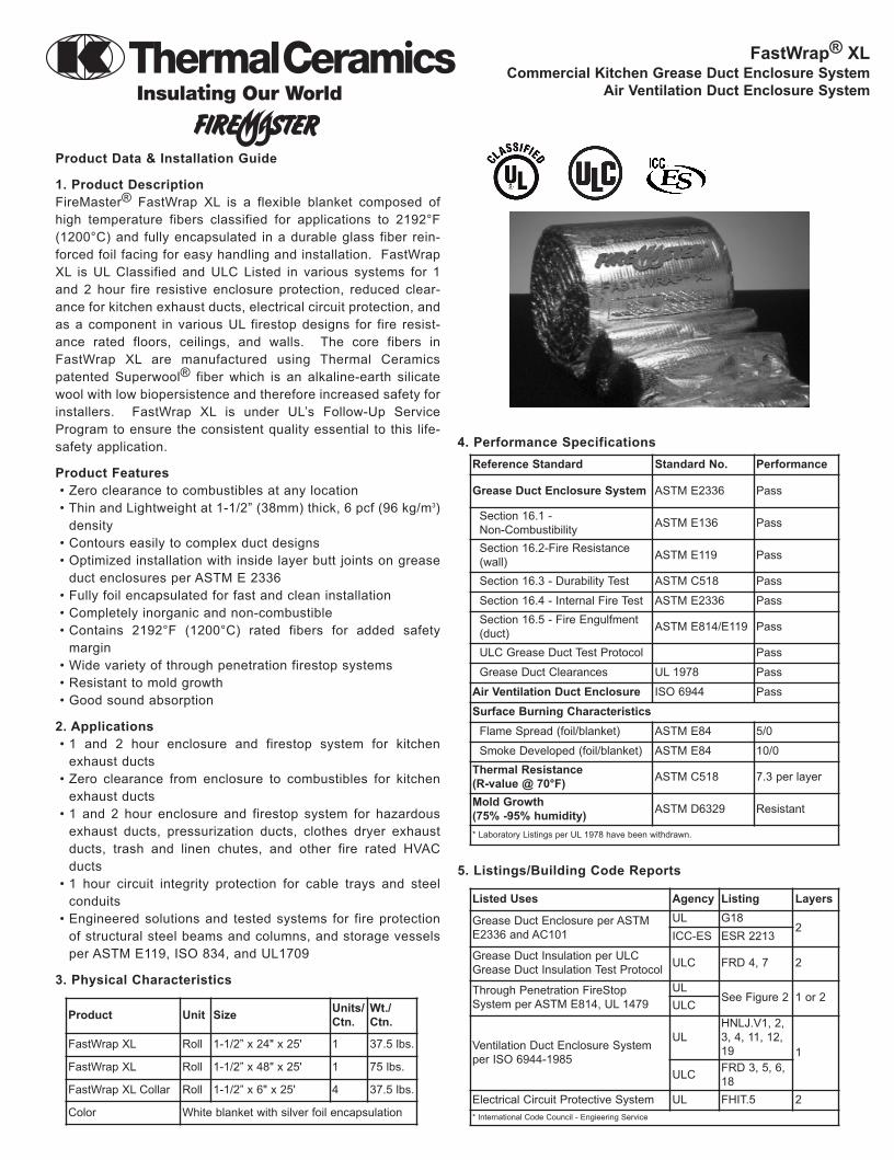
1. Product DescriptionFireMaster® FastWrap XL is a flexible blanket composed ofhigh temperature fibers classified for applications to 2192°F(1200°C) and fully encapsulated in a durable glass fiber rein-forced foil facing for easy handling and installation. FastWrapXL is UL Classified and ULC Listed in various systems for 1and 2 hour fire resistive enclosure protection, reduced clear-ance for kitchen exhaust ducts, electrical circuit protection, andas a component in various UL firestop designs for fire resist-ance rated floors, ceilings, and walls. The core fibers inFastWrap XL are manufactured using Thermal Ceramicspatented Superwool® fiber which is an alkaline-earth silicatewool with low biopersistence and therefore increased safety forinstallers. FastWrap XL is under UL’s Follow-Up ServiceProgram to ensure the consistent quality essential to this life-safety application.
Product Features• Zero clearance to combustibles at any location• Thin and Lightweight at 1-1/2” (38mm) thick, 6 pcf (96 kg/m3)
density• Contours easily to complex duct designs• Optimized installation with inside layer butt joints on grease
duct enclosures per ASTM E 2336• Fully foil encapsulated for fast and clean installation• Completely inorganic and non-combustible• Contains 2192°F (1200°C) rated fibers for added safety
margin• Wide variety of through penetration firestop systems• Resistant to mold growth• Good sound absorption
2. Applications• 1 and 2 hour enclosure and firestop system for kitchen
exhaust ducts• Zero clearance from enclosure to combustibles for kitchen
exhaust ducts • 1 and 2 hour enclosure and firestop system for hazardous
exhaust ducts, pressurization ducts, clothes dryer exhaustducts, trash and linen chutes, and other fire rated HVACducts
• 1 hour circuit integrity protection for cable trays and steelconduits
• Engineered solutions and tested systems for fire protectionof structural steel beams and columns, and storage vesselsper ASTM E119, ISO 834, and UL1709
3. Physical Characteristics
4. Performance Specifications
5. Listings/Building Code Reports
FastWrap® XLCommercial Kitchen Grease Duct Enclosure System
Air Ventilation Duct Enclosure System
Product Unit Size Units/Ctn.
Wt./Ctn.
FastWrap XL Roll 1-1/2” x 24" x 25' 1 37.5 lbs.
FastWrap XL Roll 1-1/2” x 48" x 25' 1 75 lbs.
FastWrap XL Collar Roll 1-1/2” x 6" x 25' 4 37.5 lbs.
Color White blanket with silver foil encapsulation
Reference Standard Standard No. Performance
Grease Duct Enclosure System ASTM E2336 Pass
Section 16.1 - Non-Combustibility ASTM E136 Pass
Section 16.2-Fire Resistance(wall) ASTM E119 Pass
Section 16.3 - Durability Test ASTM C518 Pass
Section 16.4 - Internal Fire Test ASTM E2336 PassSection 16.5 - Fire Engulfment(duct) ASTM E814/E119 Pass
ULC Grease Duct Test Protocol Pass
Grease Duct Clearances UL 1978 Pass
Air Ventilation Duct Enclosure ISO 6944 Pass
Surface Burning CharacteristicsFlame Spread (foil/blanket) ASTM E84 5/0
Smoke Developed (foil/blanket) ASTM E84 10/0Thermal Resistance (R-value @ 70°F) ASTM C518 7.3 per layer
Mold Growth (75% -95% humidity) ASTM D6329 Resistant
* Laboratory Listings per UL 1978 have been withdrawn.
Listed Uses Agency Listing Layers
Grease Duct Enclosure per ASTME2336 and AC101
UL G182
ICC-ES ESR 2213
Grease Duct Insulation per ULCGrease Duct Insulation Test Protocol ULC FRD 4, 7 2
Through Penetration FireStopSystem per ASTM E814, UL 1479
ULSee Figure 2 1 or 2
ULC
Ventilation Duct Enclosure Systemper ISO 6944-1985
ULHNLJ.V1, 2,3, 4, 11, 12,19 1
ULC FRD 3, 5, 6,18
Electrical Circuit Protective System UL FHIT.5 2* International Code Council - Engieering Service
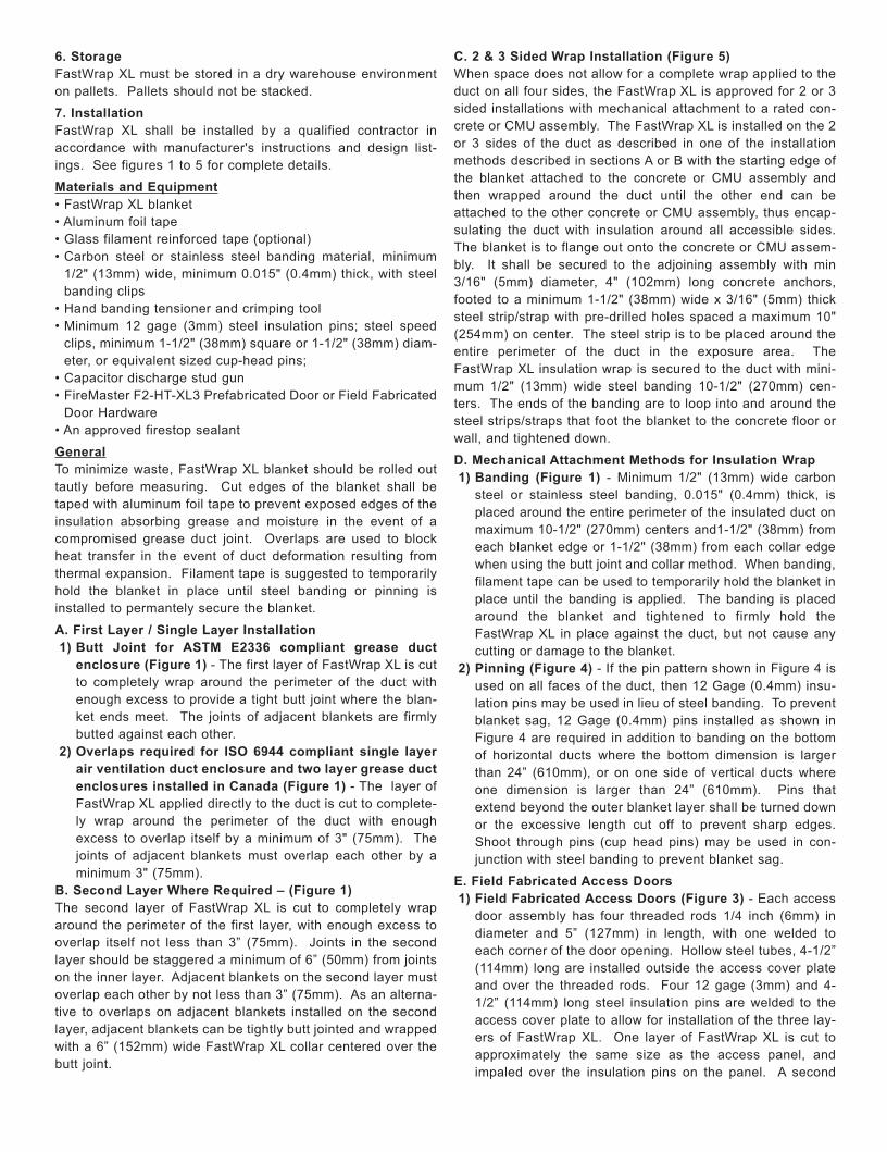
6. Storage FastWrap XL must be stored in a dry warehouse environmenton pallets. Pallets should not be stacked.
7. InstallationFastWrap XL shall be installed by a qualified contractor inaccordance with manufacturer's instructions and design list-ings. See figures 1 to 5 for complete details.
Materials and Equipment• FastWrap XL blanket• Aluminum foil tape• Glass filament reinforced tape (optional)• Carbon steel or stainless steel banding material, minimum
1/2" (13mm) wide, minimum 0.015" (0.4mm) thick, with steelbanding clips
• Hand banding tensioner and crimping tool• Minimum 12 gage (3mm) steel insulation pins; steel speed
clips, minimum 1-1/2" (38mm) square or 1-1/2" (38mm) diam-eter, or equivalent sized cup-head pins;
• Capacitor discharge stud gun• FireMaster F2-HT-XL3 Prefabricated Door or Field Fabricated
Door Hardware• An approved firestop sealant
GeneralTo minimize waste, FastWrap XL blanket should be rolled outtautly before measuring. Cut edges of the blanket shall betaped with aluminum foil tape to prevent exposed edges of theinsulation absorbing grease and moisture in the event of acompromised grease duct joint. Overlaps are used to blockheat transfer in the event of duct deformation resulting fromthermal expansion. Filament tape is suggested to temporarilyhold the blanket in place until steel banding or pinning isinstalled to permantely secure the blanket.
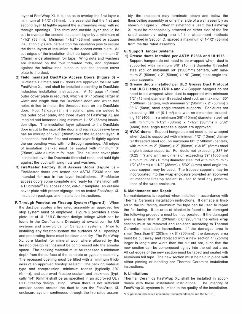
A. First Layer / Single Layer Installation1) Butt Joint for ASTM E2336 compliant grease duct
enclosure (Figure 1) - The first layer of FastWrap XL is cutto completely wrap around the perimeter of the duct withenough excess to provide a tight butt joint where the blan-ket ends meet. The joints of adjacent blankets are firmlybutted against each other.
2) Overlaps required for ISO 6944 compliant single layerair ventilation duct enclosure and two layer grease ductenclosures installed in Canada (Figure 1) - The layer ofFastWrap XL applied directly to the duct is cut to complete-ly wrap around the perimeter of the duct with enoughexcess to overlap itself by a minimum of 3" (75mm). Thejoints of adjacent blankets must overlap each other by aminimum 3" (75mm).
B. Second Layer Where Required – (Figure 1)The second layer of FastWrap XL is cut to completely wraparound the perimeter of the first layer, with enough excess tooverlap itself not less than 3” (75mm). Joints in the secondlayer should be staggered a minimum of 6” (50mm) from jointson the inner layer. Adjacent blankets on the second layer mustoverlap each other by not less than 3” (75mm). As an alterna-tive to overlaps on adjacent blankets installed on the secondlayer, adjacent blankets can be tightly butt jointed and wrappedwith a 6” (152mm) wide FastWrap XL collar centered over thebutt joint.
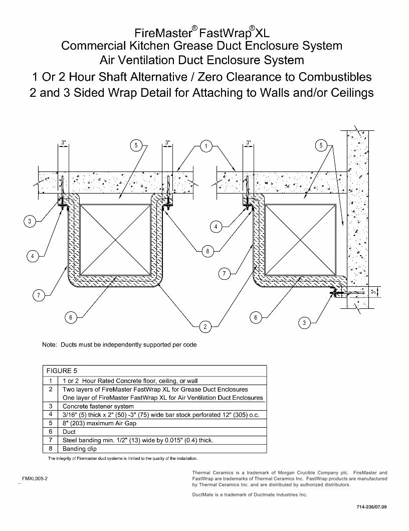
C. 2 & 3 Sided Wrap Installation (Figure 5)When space does not allow for a complete wrap applied to theduct on all four sides, the FastWrap XL is approved for 2 or 3sided installations with mechanical attachment to a rated con-crete or CMU assembly. The FastWrap XL is installed on the 2or 3 sides of the duct as described in one of the installationmethods described in sections A or B with the starting edge ofthe blanket attached to the concrete or CMU assembly andthen wrapped around the duct until the other end can beattached to the other concrete or CMU assembly, thus encap-sulating the duct with insulation around all accessible sides.The blanket is to flange out onto the concrete or CMU assem-bly. It shall be secured to the adjoining assembly with min3/16" (5mm) diameter, 4" (102mm) long concrete anchors,footed to a minimum 1-1/2" (38mm) wide x 3/16" (5mm) thicksteel strip/strap with pre-drilled holes spaced a maximum 10"(254mm) on center. The steel strip is to be placed around theentire perimeter of the duct in the exposure area. TheFastWrap XL insulation wrap is secured to the duct with mini-mum 1/2" (13mm) wide steel banding 10-1/2" (270mm) cen-ters. The ends of the banding are to loop into and around thesteel strips/straps that foot the blanket to the concrete floor orwall, and tightened down.
D. Mechanical Attachment Methods for Insulation Wrap1) Banding (Figure 1) - Minimum 1/2" (13mm) wide carbon
steel or stainless steel banding, 0.015" (0.4mm) thick, isplaced around the entire perimeter of the insulated duct onmaximum 10-1/2" (270mm) centers and1-1/2" (38mm) fromeach blanket edge or 1-1/2" (38mm) from each collar edgewhen using the butt joint and collar method. When banding,filament tape can be used to temporarily hold the blanket inplace until the banding is applied. The banding is placedaround the blanket and tightened to firmly hold theFastWrap XL in place against the duct, but not cause anycutting or damage to the blanket.
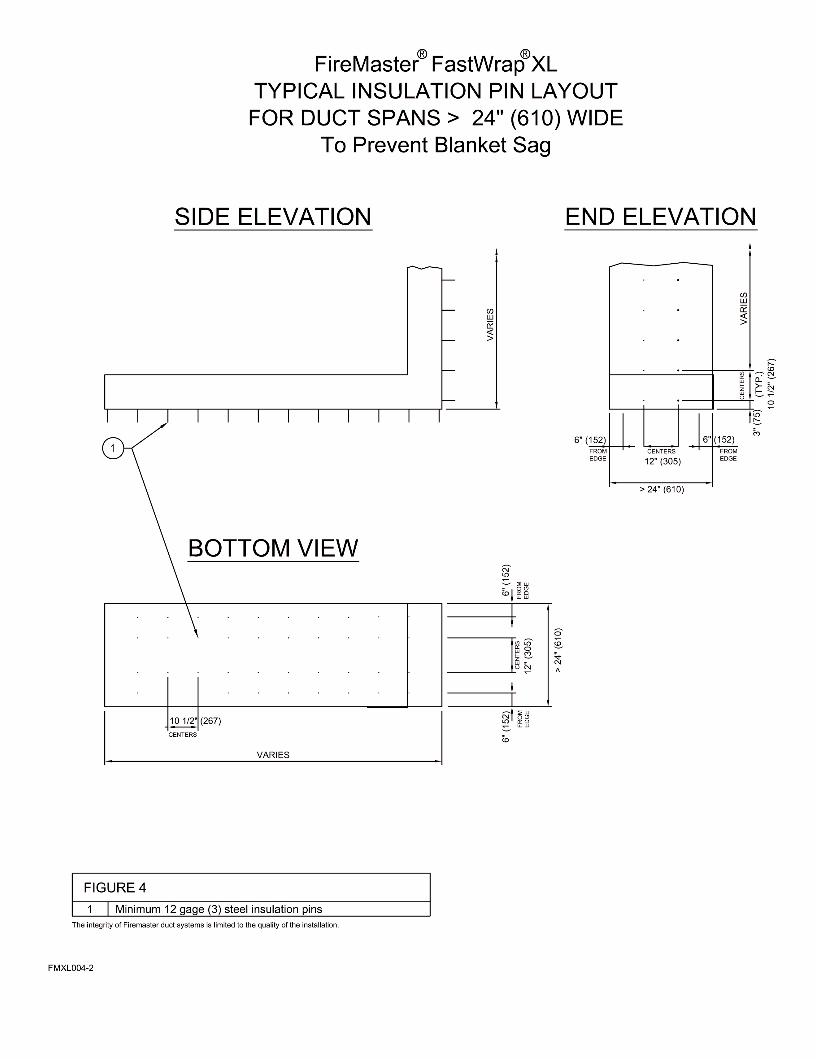
2) Pinning (Figure 4) - If the pin pattern shown in Figure 4 isused on all faces of the duct, then 12 Gage (0.4mm) insu-lation pins may be used in lieu of steel banding. To preventblanket sag, 12 Gage (0.4mm) pins installed as shown inFigure 4 are required in addition to banding on the bottomof horizontal ducts where the bottom dimension is largerthan 24” (610mm), or on one side of vertical ducts whereone dimension is larger than 24” (610mm). Pins thatextend beyond the outer blanket layer shall be turned downor the excessive length cut off to prevent sharp edges.Shoot through pins (cup head pins) may be used in con-junction with steel banding to prevent blanket sag.
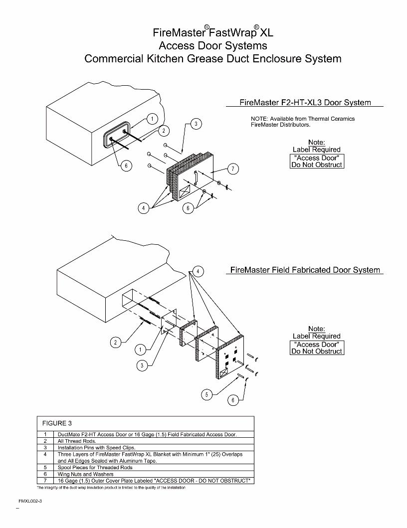
E. Field Fabricated Access Doors1) Field Fabricated Access Doors (Figure 3) - Each access
door assembly has four threaded rods 1/4 inch (6mm) indiameter and 5” (127mm) in length, with one welded toeach corner of the door opening. Hollow steel tubes, 4-1/2”(114mm) long are installed outside the access cover plateand over the threaded rods. Four 12 gage (3mm) and 4-1/2” (114mm) long steel insulation pins are welded to theaccess cover plate to allow for installation of the three lay-ers of FastWrap XL. One layer of FastWrap XL is cut toapproximately the same size as the access panel, andimpaled over the insulation pins on the panel. A second
layer of FastWrap XL is cut so as to overlap the first layer aminimum of 1-1/2” (38mm). It is essential that the first andsecond layer fit tightly against the surrounding wrap with nothrough openings. The third and outside layer should becut to overlap the second insulation layer by a minimum of1-1/2” (38mm). Minimum 1-1/2” (38mm) round or squareinsulation clips are installed on the insulation pins to securethe three layers of insulation to the access cover plate. Allcut edges of the insulation shall be taped with minimum 3”(75mm) wide aluminum foil tape. Wing nuts and washersare installed on the four threaded rods, and tightenedagainst the hollow steel tubes to seal the access coverplate to the duct.
2) Field Insulated DuctMate Access Doors (Figure 3) –DuctMate Ultimate and F2 doors are approved for use withFastWrap XL, and shall be installed according to DuctMateIndustries installation instructions. A 16 gage (1.4mm)outer cover plate is required, which is 6” (152mm) larger inwidth and length than the DuctMate door, and which hasholes drilled to match the threaded rods on the DuctMatedoor. Four 12 gage (3mm) insulation pins are welded tothis outer cover plate, and three layers of FastWrap XL areimpaled and fastened using minimum 1-1/2” (38mm) insula-tion clips. The insulation layer adjacent to the DuctMatedoor is cut to the size of the door and each successive layerhas an overlap of 1-1/2” (38mm) over the adjacent layer. Itis essential that the first and second layer fit tightly againstthe surrounding wrap with no through openings. All edgesof insulation blanket must be sealed with minimum 3”(75mm) wide aluminum foil tape. The insulated cover plateis installed over the Ductmate threaded rods, and held tightagainst the duct with wing nuts and washers.
3) FireMaster Factory Built Access Doors (Figure 3) –FireMaster doors are tested per ASTM E2336 and areintended for use in two layer installations. FireMasteraccess doors come complete and ready for installation witha DuctMate® F2 access door, cut-out template, an outsidecover plate with proper signage, an as tested FastWrap XLinsulation package, and installation instructions.
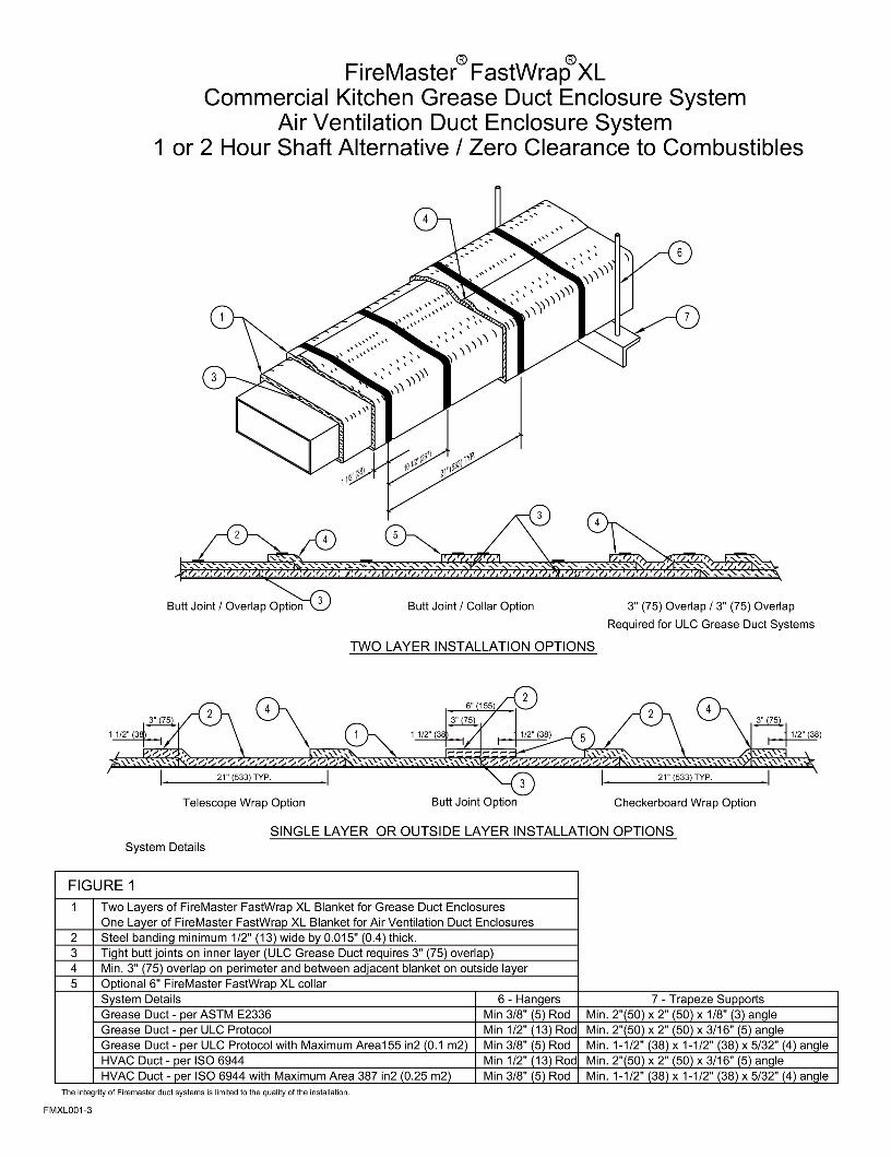
F. Through Penetration Firestop System (Figure 2) - Whenthe duct penetrates a fire rated assembly an approved firestop system must be employed. Figure 2 provides a com-plete list of UL / ULC firestop design listings which can befound in the Certifications Directory at www.ul.com for USsystems and www.ulc.ca for Canadian systems. Prior toinstalling any firestop system the surfaces of all openingsand penetrating items must be clean and dry. The FastWrapXL core blanket (or mineral wool where allowed by thefirestop design listing) must be compressed into the annularspace. The packing material must be recessed a minimumdepth from the surface of the concrete or gypsum assembly.The recessed opening must be filled with a minimum thick-ness of an approved firestop sealant. The packing materialtype and compression, minimum recess (typically 1/4”(6mm)), and approved firestop sealant and thickness (typi-cally 1/4” (6mm)) shall be as specified in an approved UL /ULC firestop design listing. When there is not sufficientannular space around the duct to run the FastWrap XLenclosure system continuous through the fire rated assem-
bly, the enclosure may terminate above and below thefloor/ceiling assembly or on either side of a wall assembly asshown in Figure 2. When this method is used, the FastWrapXL must be mechanically attached on either side of the firerated assembly using one of the attachment methodsdescribed in Section D, spaced a maximum of 1-1/2” (38mm)from the fire rated assembly.
G. Support Hanger Systems1) Grease ducts installed per ASTM E2336 and UL1978 –
Support hangers do not need to be wrapped when duct issupported with minimum 3/8” (10mm) diameter threadedsteel rod, on maximum 60” (1500mm) centers, with mini-mum 2” (50mm) x 2” (50mm) x 1/8” (3mm) steel angle tra-peze supports.
2) Grease ducts installed per ULC Grease Duct Protocoland ULC Listings FRD 4 and 7 – Support hangers do notneed to be wrapped when duct is supported with minimum1/2” (13mm) diameter threaded steel rod, on maximum 60”(1500mm) centers, with minimum 2” (50mm) x 2” (50mm) x3/16” (5mm) steel angle trapeze supports. For ducts notexceeding 155 in2 (0.1 m2) and with no dimension exceed-ing 16” (406mm) a minimum 3/8” (10mm) diameter steel rodwith minimum 1-1/2” (38mm) x 1-1/2” (38mm) x 5/32”(4mm) steel angle trapeze support are approved.
3) HVAC ducts – Support hangers do not need to be wrappedwhen duct is supported with minimum 1/2” (13mm) diame-ter threaded steel rod, on maximum 60” (1500mm) centers,with minimum 2” (50mm) x 2” (50mm) x 3/16” (5mm) steelangle trapeze supports. For ducts not exceeding 387 in2
(0.25 m2) and with no dimension exceeding 39” (1000mm)a minimum 3/8” (10mm) diameter steel rod with minimum 1-1/2” (38mm) x 1-1/2” (38mm) x 5/32” (4mm) steel angle tra-peze support may be used. The trapeze supports may beincorporated into the wrap enclosure provided an approvedintumescent firestop sealant is used to seal any penetra-tions of the wrap enclosure.
8. Maintenance and RepairNo maintenance is required when installed in accordance withThermal Ceramics installation instructions. If damage is limit-ed to the foil facing, aluminum foil tape can be used to repairthe foil facing. If an area of blanket is found to be damagedthe following procedure must be incorporated. If the damagedarea is larger than 8” (203mm) x 8” (203mm) the entire wrapsection must be removed and replaced according to ThermalCeramics installation instructions. If the damaged area issmall (less than 8” (203mm) x 8” (203mm)), the damaged areamust be cut away and replaced with a new section 1” (25mm)larger in length and width than the cut out are, such that thenew section can be compressed tightly into the cut out area.All cut edges of the new section must be taped and sealed wthaluminum foil tape. The new section must be held in place witheither pinning or banding per Thermal Ceramics installationinstructions.
9. LimitationsThermal Ceramics FastWrap XL shall be installed in accor-dance with these installation instructions. The integrity ofFastWrap XL systems is limited to the quality of the installation.
*For personal protective equipment recommendations see the MSDS.
Thermal Ceramics is a trademark of Morgan Crucible Company plc. FireMaster andFastWrap are trademarks of Thermal Ceramics Inc. FastWrap products are manufacturedby Thermal Ceramics Inc. and are distributed by authorized distributors.
DuctMate is a trademark of Ductmate Industries Inc.
714-236/07.09