Embed Size (px)
Citation preview
1
Fast quench problems and how they damage coke drums
Coke Drum Reliability Workshop
Calgary • September 17, 2009
Richard Boswell, P.E.Stress Engineering Services, Inc
Principal
2
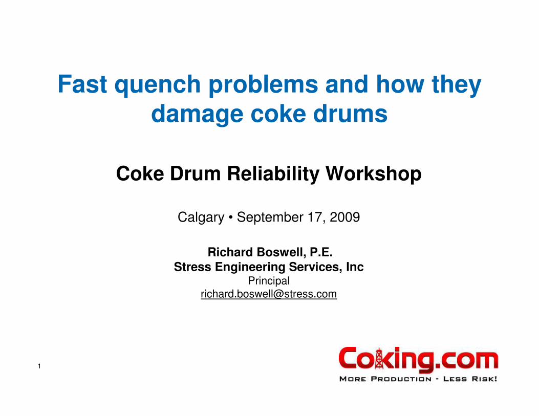
Classic Drum Deformation For Low Alloy Drums
• Permanent deformation pattern of vessels in cyclic service
• Skirt is attached to the cylinder by welding
Weil and Murphy
(Kellogg 1960, ASME)
3
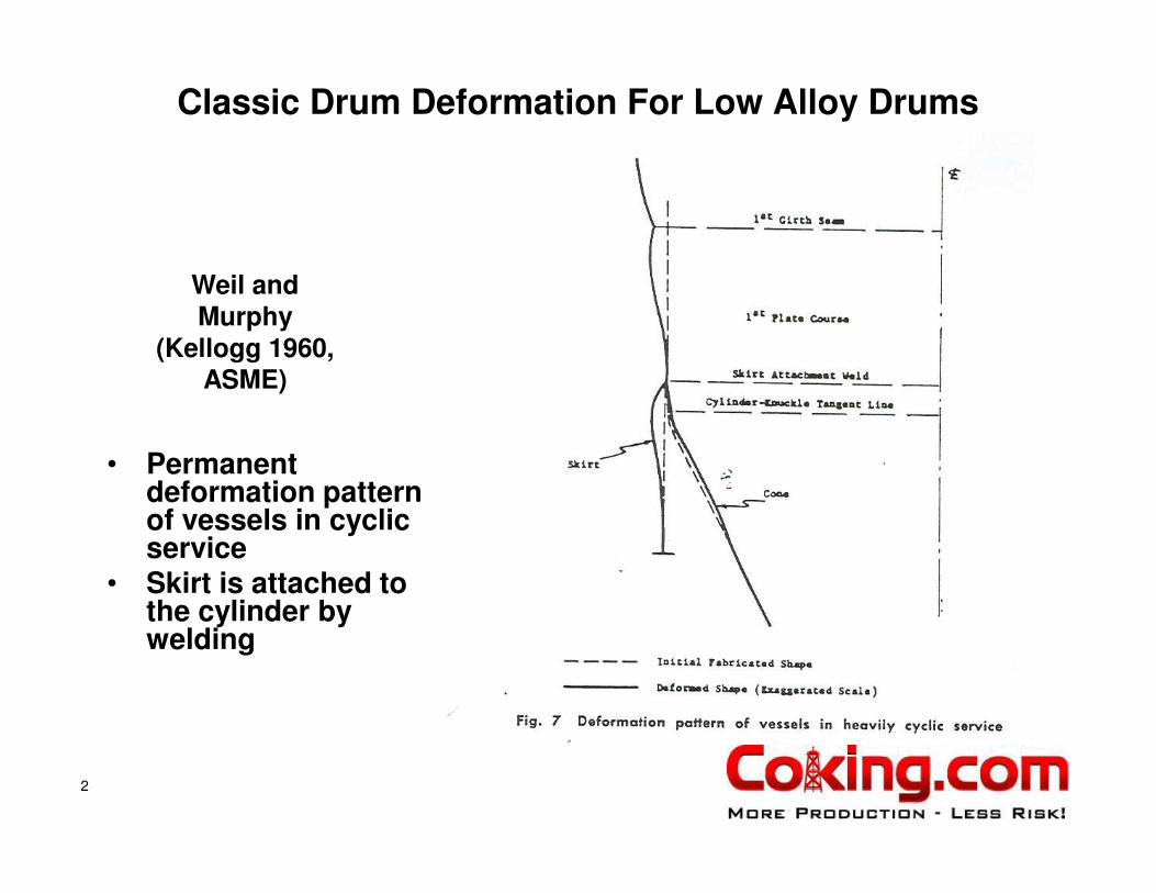
Problem Circ Weld Seam* Cracking Is Common
* Joint detail may vary
4
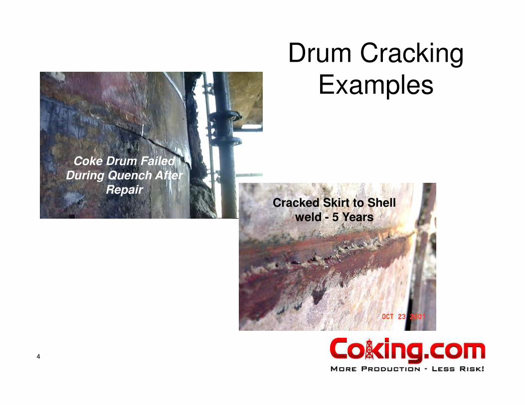
Coke Drum Failed
During Quench After
RepairCracked Skirt to Shell
weld - 5 Years
Drum Cracking
Examples

5
A NOTABLE
QUENCH
STRESS
MEASURED
ON SHELL
O.D.

6
A Measured Cycle For In-Line Skirt Stress Response (OD)
Temperature
Hoop Stress
Axial Stress

7
Cone
Skirt
Cone Peak Thermal Rate
8
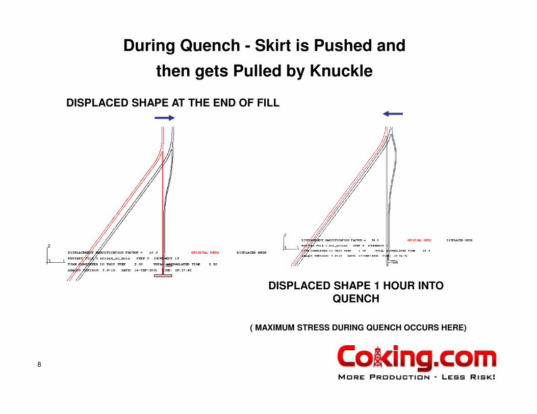
DISPLACED SHAPE AT THE END OF FILL
DISPLACED SHAPE 1 HOUR INTO QUENCH
( MAXIMUM STRESS DURING QUENCH OCCURS HERE)
During Quench - Skirt is Pushed and
then gets Pulled by Knuckle

9
Example
Bending
Stress
Distribution

10
Example In-Line Skirt Axial Stress During the Fill Transient
Axial
Bending
Stress
Gap Radiation
Note high bending stresses as hotter
cone PUSHES Skirt
top Outward
11
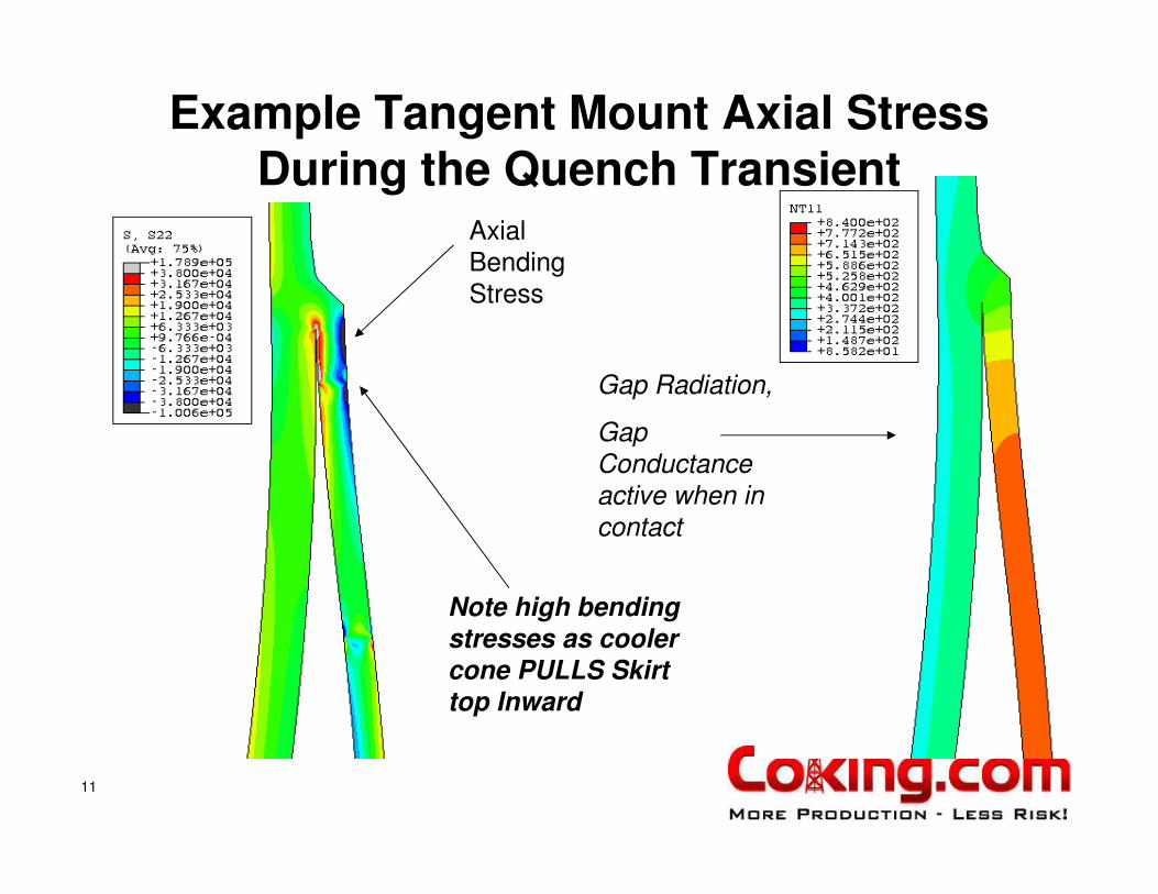
Example Tangent Mount Axial Stress During the Quench Transient
Axial
Bending
Stress
Gap Radiation,
Gap
Conductance
active when in
contact
Note high bending
stresses as cooler
cone PULLS Skirt top Inward

12
FATIGUE LIFE CALCULATION FOR A SKIRT IS MORE ACCURATE USING MEASURED THERMAL TRANSIENT
•Design (by others)
predicted 152 years
•SES Transient analysis
performed prior to T/A
•Maximum stress
intensity range during
transient = 143,430 psi
• Using ASME code
Section VIII Division 2
fatigue design Table 5-
110.1, UTS < 80 ksi, a
fatigue life of 1228cycles was obtained.
After 5 years (~1369 cycles) cracks were discovered in all 4 drum skirts (no slots) prior to T/A
Finite Element Model vs Reality

13
Thermal Cycles and Rates for Cone

14
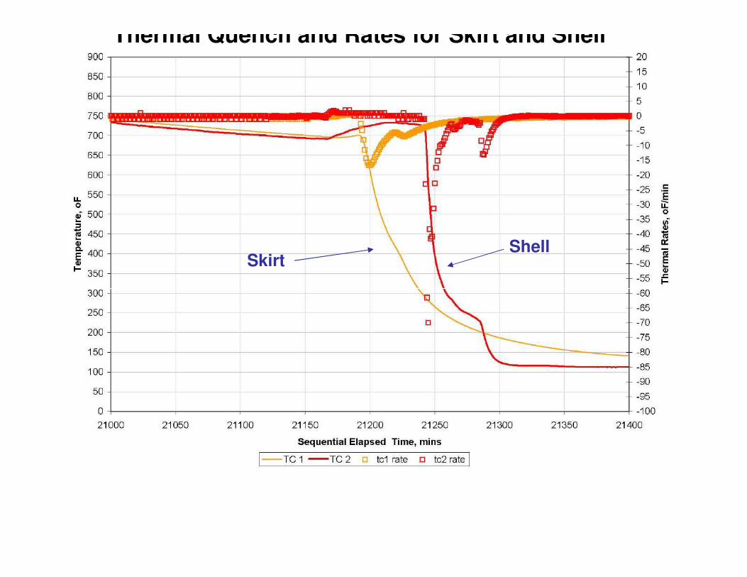
Thermal Cycles and Rates for Skirt and Shell
15
SkirtShell
Thermal Quench and Rates for Skirt and Shell

16
Does Fast Quench Shorten Cyclic
Life ?
• Where Does Fast Quench Hurt?– Skirt Attachment Weld
– Shell Circ Seams
– Cone Circ Seams
• Why Does Fast Quench Hurt?– Constraint created by components at different
temperatures (i.e. thermal expansions)
– Different Material Properties (Yield, Expansion, Conductivity, Diffusivity)

17
FEA Transient Analysis for ID Circ Seam
Base Metal
Cladding
Weld Overlay

18
Stress Distribution Across Weld During Quench
for Linear Elastic Fracture Mechanics EvaluationStress Distribution Below the Weld
Just Below Weld Cap
-20000
-10000
0
10000
20000
30000
40000
50000
0 0.2 0.4 0.6 0.8 1 1.2 1.4 1.6
Distance from ID (inches)
Str
ess (
psi)
Radial
Axial
Hoop
Shear
High StressAt Interface of
Cladding

19
Fast Quench Issues• Traditional Analysis methods assume a uniform average flow of
water upwards to remove heat from coke bed and shell at same time, or up thru central primary flow channel.
• Coke bed formation determines path of least resistance for water flow– Flow channel area and friction
• Plugging and channel collapse creates new flow paths
– Permeability– Porosity– Collapse strength of coke matrix
• Temperature measurements suggest fast quench with flow near wall is common– Generally random and not necessarily aligned with Inlet Nozzle
• This creates greater stress in shell/cladding bond and skirt weld– Creates greater stress at circ seams tri-metal junction
• This increases likelihood that hot zones remain in coke bed after quench

20
What to do about Fast Quench ?
• Change the way you do it
• Use Sensor Measurements (TC and HTSG) to guide you
• Use your Process Technology experts to address the possible procedures and maintain production
• Change the way drums are made
• Or, be prepared for continued problems….
DeltaValve Listened
Feasibility Studies conducted by SES
• New Inlet Nozzle Concept
• New Skirt Concepts: The Next Generation

New Skirt Concept: The Next Generation

Linkage Support Concept – Continuous Rings
Number of gussets/links = 24

Linkage Support Concept – Continuous Rings
Number of gussets/links = 24
Pinned Connections
Linkage supported on Tabletop or short Skirt
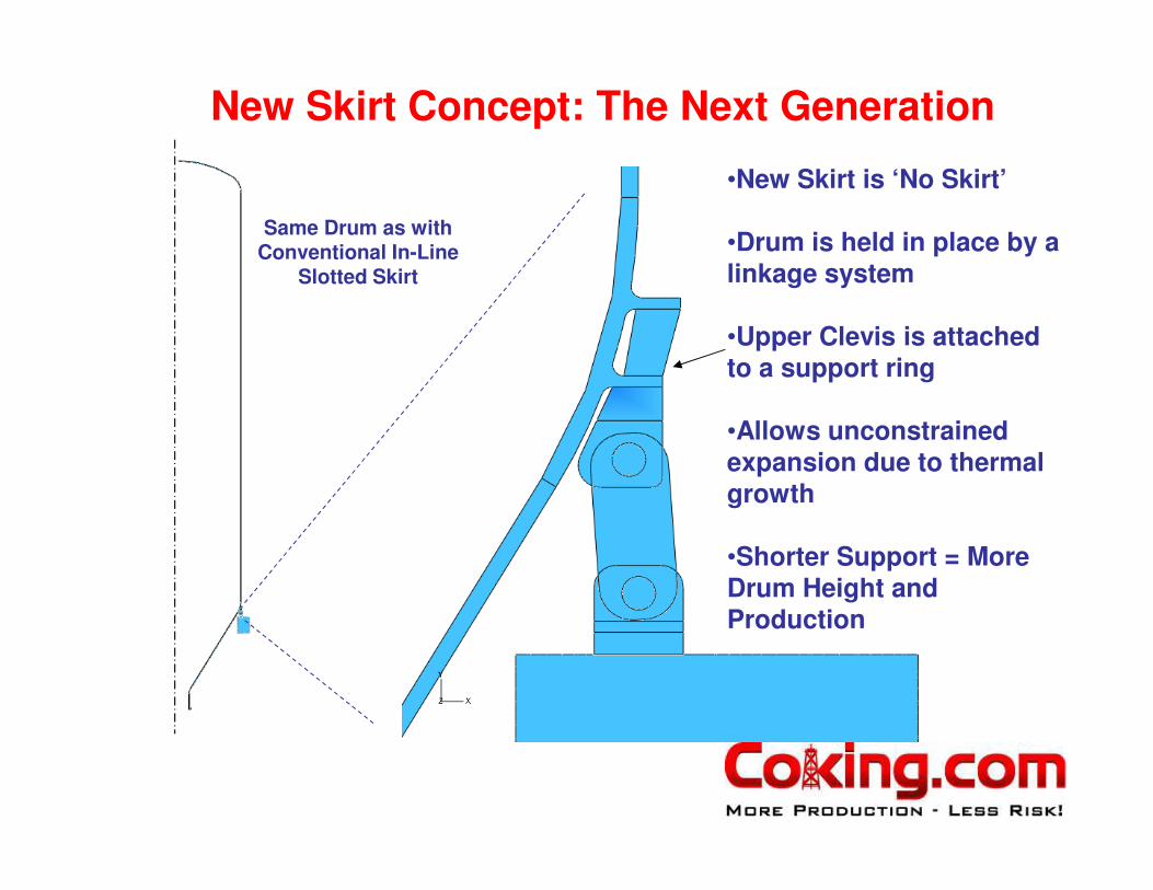
New Skirt Concept: The Next Generation
•New Skirt is ‘No Skirt’
•Drum is held in place by a linkage system
•Upper Clevis is attached to a support ring
•Allows unconstrained expansion due to thermal growth
•Shorter Support = More Drum Height and Production
Same Drum as with Conventional In-Line
Slotted Skirt

Typical Coke Drum Example for Comparison of Support ConceptsSupplied by DeltaValve
180 in. Internal Radius
Drum Weight ~ 729,000 lb
Drum Diameter = 30 ft
1200 in (tan to tan)
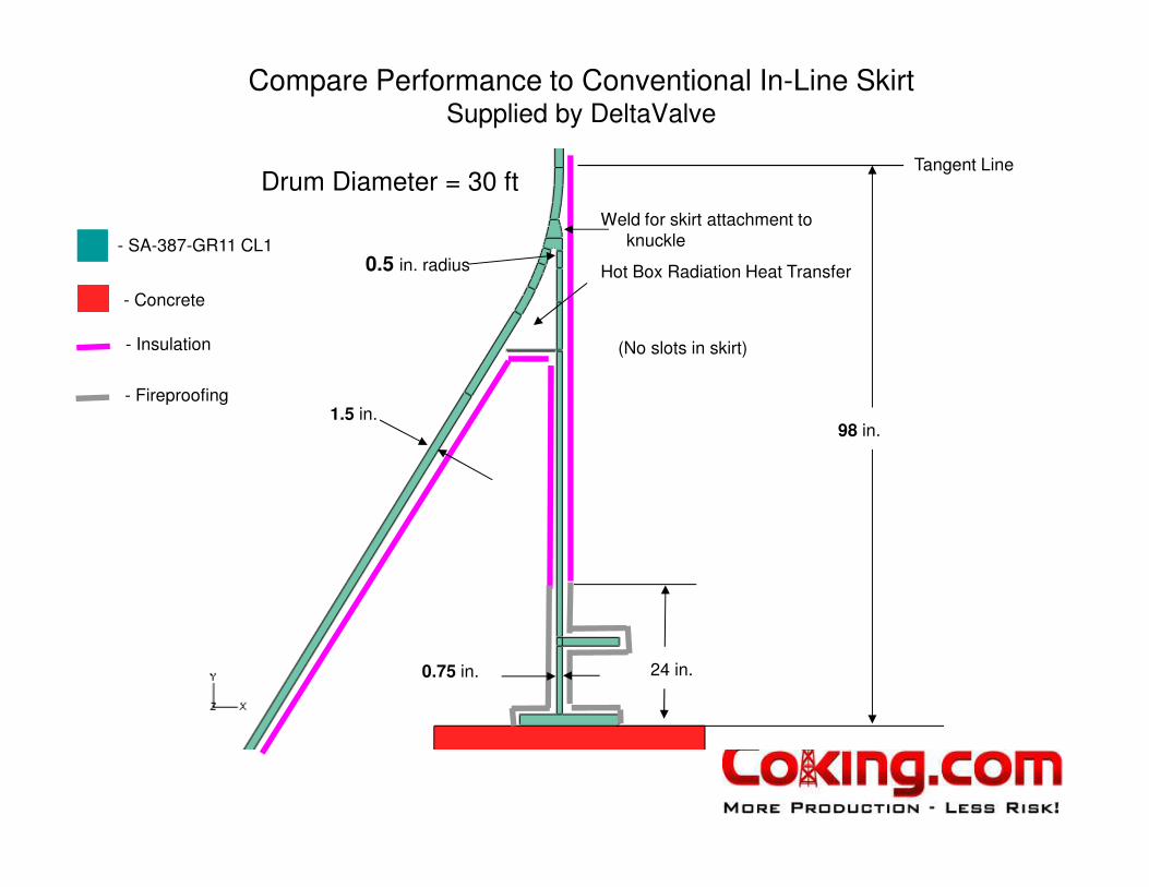
Compare Performance to Conventional In-Line SkirtSupplied by DeltaValve
- Concrete
- SA-387-GR11 CL1
0.75 in.
98 in.
24 in.
- Insulation
- Fireproofing1.5 in.
Tangent Line
Hot Box Radiation Heat Transfer
(No slots in skirt)
Drum Diameter = 30 ft
0.5 in. radius
Weld for skirt attachment to
knuckle
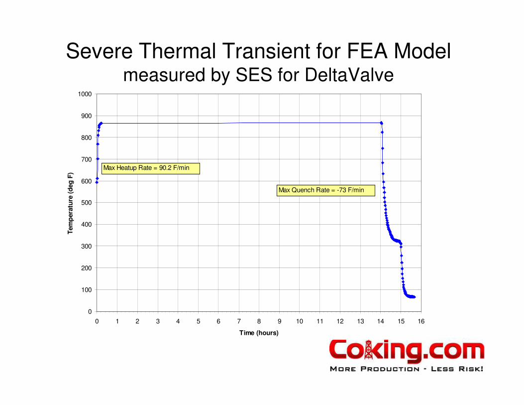
Severe Thermal Transient for FEA Modelmeasured by SES for DeltaValve
0
100
200
300
400
500
600
700
800
900
1000
0 1 2 3 4 5 6 7 8 9 10 11 12 13 14 15 16
Time (hours)
Tem
pera
ture
(d
eg
F)
Max Heatup Rate = 90.2 F/min
Max Quench Rate = -73 F/min
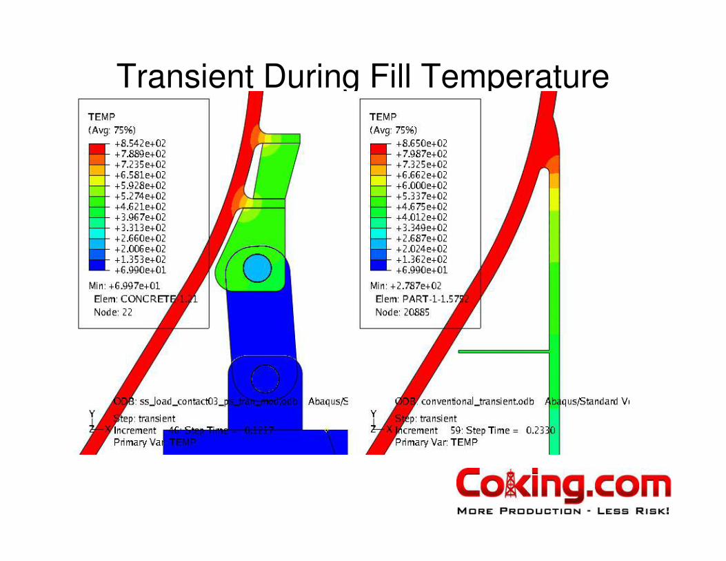
Transient During Fill Temperature
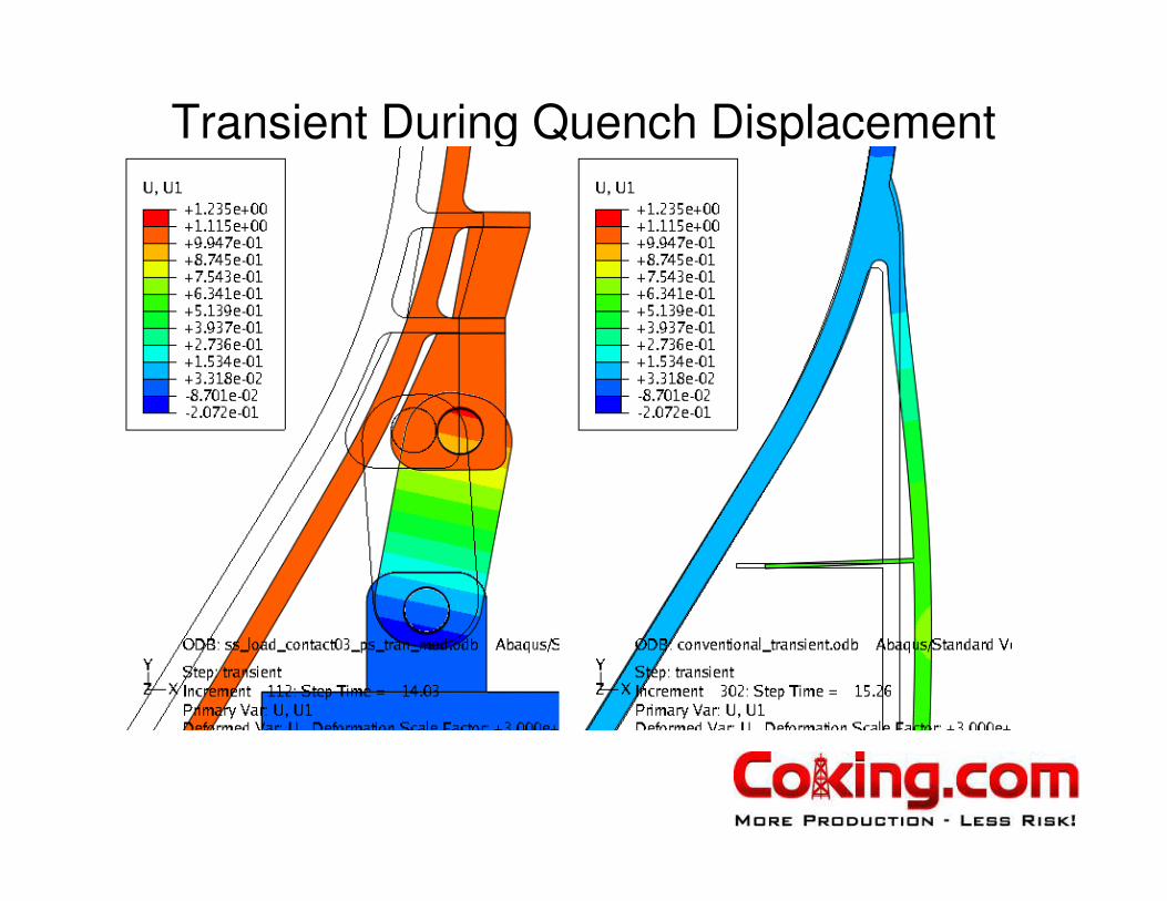
Transient During Quench Displacement
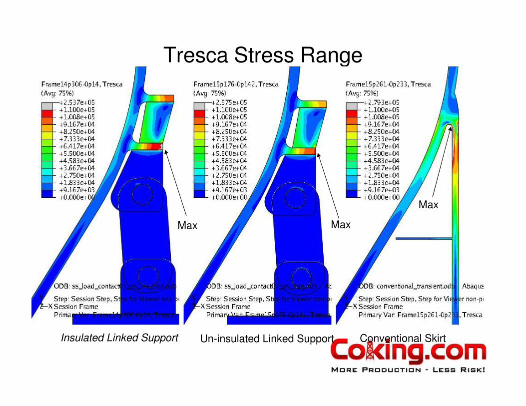
Tresca Stress Range
Max MaxMax
Insulated Linked Support Un-insulated Linked Support Conventional Skirt
Max Max
Max

Low Cycle Fatigue Calculations
Stress Ranges interpreted for Design Cyclic Life
• Conventional In-Line Skirt (1/2” radius) at top
of skirt on ID max stress range = 277,856 psi
– Design Cycle life = 234 cycles
– Note: a similar design was evaluated for client with
measured but less sever Fill thermal rate and similar
Quench rate. Total life predicted was 408 cycles
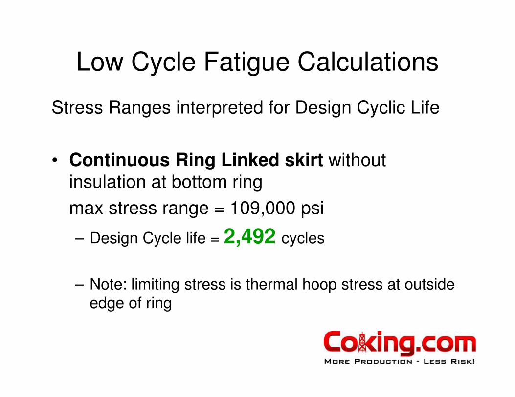
Low Cycle Fatigue Calculations
Stress Ranges interpreted for Design Cyclic Life
• Continuous Ring Linked skirt without
insulation at bottom ring
max stress range = 109,000 psi
– Design Cycle life = 2,492 cycles
– Note: limiting stress is thermal hoop stress at outside
edge of ring
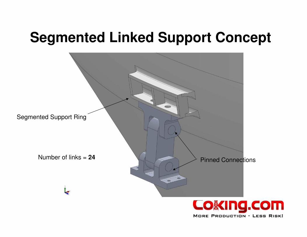
Segmented Linked Support Concept
Number of links = 24 Pinned Connections
Segmented Support Ring

Tresca Stress Range (view 1)
Conventional Skirt

Tresca Stress Range (view 2)
Conventional Skirt

Fatigue Node Locations Selected –
Segmented Linked SupportLowest Fatigue Life
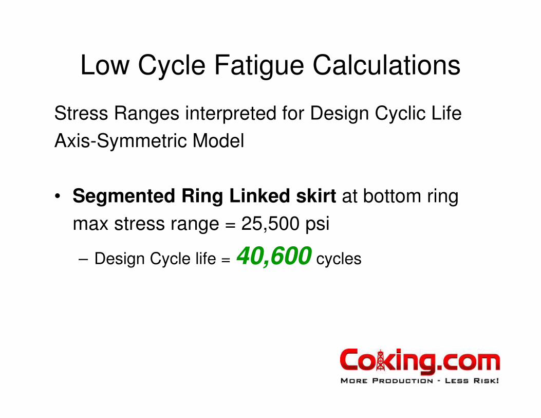
Low Cycle Fatigue Calculations
Stress Ranges interpreted for Design Cyclic Life
Axis-Symmetric Model
• Segmented Ring Linked skirt at bottom ring
max stress range = 25,500 psi
– Design Cycle life = 40,600 cycles

3D Model –
Segmented Linked Support
Symmetry PlanesSymmetry was used to reduce computation time

Coking Cycle – 867°F – Temperature
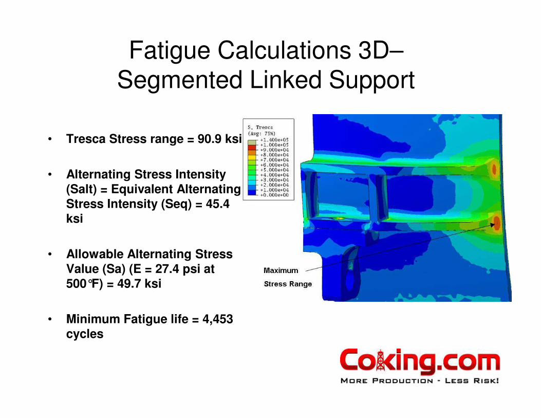
Fatigue Calculations 3D–
Segmented Linked Support
• Tresca Stress range = 90.9 ksi
• Alternating Stress Intensity (Salt) = Equivalent Alternating Stress Intensity (Seq) = 45.4 ksi
• Allowable Alternating Stress Value (Sa) (E = 27.4 psi at 500°F) = 49.7 ksi
• Minimum Fatigue life = 4,453 cycles
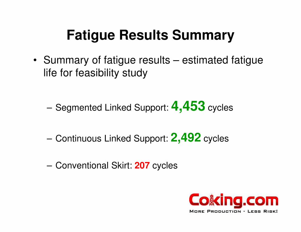
Fatigue Results Summary
• Summary of fatigue results – estimated fatigue
life for feasibility study
– Segmented Linked Support: 4,453 cycles
– Continuous Linked Support: 2,492 cycles
– Conventional Skirt: 207 cycles

Stress Engineering Services
DV Project Team +
Richard BoswellRyan Schmidt
Derek BeimgrabenSteve HoysanHarbi PortalBrian Lance
Mac SammanJulian Bedoya

Design Analysis Insert Nozzle
• Apply thermal design transient to insert nozzle
• Evaluate thermal expansions and deformations for seal design
• Evaluate Low Cycle Fatigue Life
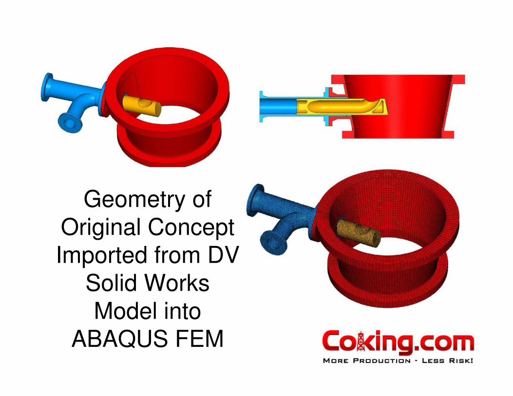
Geometry of
Original Concept
Imported from DV
Solid Works
Model into
ABAQUS FEM


Drum Flow Analysis using CFD
• Simulate flow patterns for initial condition into empty drum
• Compare
– Convention bottom center feed
– Modern Horizontal Inlet feed
• Straight Side Entry
• Elbow Side Entry
– New Generation Insert Nozzle feed

PN 123971
Analysis Method – Flow Rates
Condition #1 (data gathered from literature)
• The flow rate into the coke drum depends on the process cycle time and refinery throughput. The flow rate through the drum is estimated.
• Analysis is carried out using an inflow velocity of 17 m/s (55 ft/sec) in the feed pipe.
Condition #2 (data gathered from plant simulation by Sim Romero of KBC AT)
• Flow rate into drum 421880 lb/hr (~53. Kg/sec or ~2.24 m3/sec).
• This corresponds to an inflow velocity of 62.4 m/s in the feed pipe.
PN 123995

PN 123971
Results Traditional Bottom Center Feed Nozzle
PN 123995
Velocity (m/s) (on Plane 1)
A close examination of the simulations indicate unsteady flow behavior in the coke drum for the simulated conditions. This aspect is investigated by examining the flow distribution at various time instants.
Centered flow is observed when a centrally located traditional nozzle is used
The simulations represent the beginning of the coking process when VRC vapor is injected into an empty drum
Flow is well centered
PN 123971
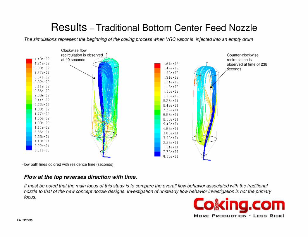
Results – Traditional Bottom Center Feed Nozzle
PN 123995
Flow path lines colored with residence time (seconds)
Flow at the top reverses direction with time.
It must be noted that the main focus of this study is to compare the overall flow behavior associated with the traditional
nozzle to that of the new concept nozzle designs. Investigation of unsteady flow behavior investigation is not the primary
focus.
The simulations represent the beginning of the coking process when VRC vapor is injected into an empty drum
Clockwise flow
recirculation is observed
at 40 seconds
Counter-clockwise
recirculation is
observed at time of 238
seconds

PN 123995
Analysis MethodFlow Geometry ( Straight Side-Entry Nozzle)
The nozzle is placed in a representative coke drum.
Close up of straight side-entry inlet feed nozzle and spool region

PN 123971
Results – Straight Side-entry Nozzle, Flow Condition #2
PN 123995
Velocity (m/s) (on Plane 1)
The simulations represent the beginning of the coking process when VRC vapor is injected into an empty drum
Flow impinges upon
the drum wall

PN 123971
Results – Straight Side-entry Nozzle, Flow Condition #2
PN 123995
Velocity (m/s) (on Plane 1)
Red color denotes velocity of 5 m/s . The white region next to red denotes velocity higher than 5 m/s
The simulations represent the beginning of the coking process when VRC vapor is injected into an empty drum
Flow velocity along the wall
is 5m/s or higher
Slight unsteadiness is observed in the
flow in the upper portion of the drum.
This aspect is not explored in detail as
the overall flow pattern inside the drum
is almost unchanged.

PN 123971
Results – Straight Side-entry Nozzle, Flow Condition #2
PN 123995
Path lines of flow originating
at the inlet
The simulations represent the beginning of the coking process when VRC vapor is injected into an empty drum
The analysis and path lines shows that the flow
impinges upon the drum wall. The impingement
causes the flow to disperse partially around the
circumference of the drum; the flow then rises
vertically upwards along the walls of the drum.
Rising flow
Alternate view

PN 123971
Results – Straight Side-entry Nozzle, Flow Condition #2
PN 123995
Velocity (m/s) (on Plane 1)
The simulations represent the beginning of the coking process when VRC vapor is injected into an empty drum
Close up view of flow in the inlet region
Flow impinges upon
the drum wall
Recirculation region
beneath the inlet
PN 123971
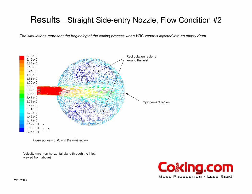
Results – Straight Side-entry Nozzle, Flow Condition #2
PN 123995
Velocity (m/s) (on horizontal plane through the inlet;
viewed from above)
The simulations represent the beginning of the coking process when VRC vapor is injected into an empty drum
Close up view of flow in the inlet region
Impingement region
Recirculation regions
around the inlet

PN 123971
Results – Straight Side-entry Nozzle, Flow Condition #2
PN 123995
Path lines of flow originating at the inlet
The simulations represent the beginning of the coking process when VRC vapor is injected into an empty drum
View from above
Upon impingement flow spreads upwards and
around the circumferential direction on the wall
Some flow is also directed beneath the inlet

PN 123971
Results – Straight Side-entry Nozzle, Flow Condition #2
PN 123995
Path lines of flow originating at the inlet
The simulations represent the beginning of the coking process when VRC vapor is injected into an empty drum
Upon impingement flow spreads upwards and
around the circumferential direction on the wall
Some flow is also directed beneath the inlet
Flow that is directed beneath the inlet rises and loops
around to join the upward flow on the wall at the wall of
the drum
This looping generates a high three-dimensional and
complex flow pattern

PN 123995
Analysis MethodFlow Geometry (side-entry elbow nozzle)
The elbow style nozzle is placed in a representative coke drum.
Close up of side-entry inlet feed nozzle and spool region

PN 123971
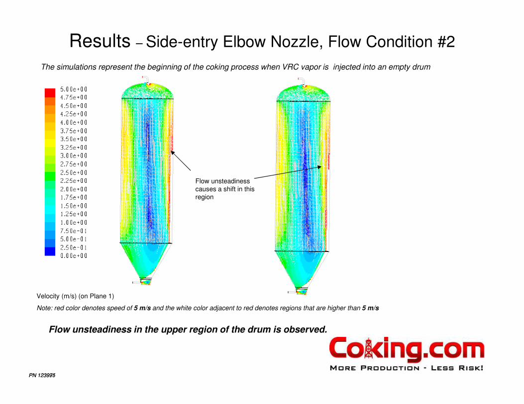
Results – Side-entry Elbow Nozzle, Flow Condition #2
PN 123995
Velocity (m/s) (on Plane 1)
A close examination of the simulations indicate unsteady flow behavior in the coke drum for the simulated conditions. This aspect is investigated by examining the flow distribution at various time instants.
The simulations represent the beginning of the coking process when VRC vapor is injected into an empty drum
Flow is impinges upon
the drum wall
Path lines depicting the rising and
falling flow inside the drum
Rising flow
Falling flow
PN 123971
Results – Side-entry Elbow Nozzle, Flow Condition #2
PN 123995
Velocity (m/s) (on Plane 1)
Note: red color denotes speed of 5 m/s and the white color adjacent to red denotes regions that are higher than 5 m/s
Flow unsteadiness in the upper region of the drum is observed.
The simulations represent the beginning of the coking process when VRC vapor is injected into an empty drum
Flow unsteadiness
causes a shift in this
region

PN 123971
Results – New Concept Nozzle (Design modification 1)
PN 123995
Velocity (m/s)
Close up of flow at the nozzleFlow path lines colored with residence
time (seconds)
Flow leaves the nozzle at an angle
Unsteady flow behavior at the top of the drum is observed.
However, the unsteadiness is quite weak and is not explored in any detail
The simulations represent the beginning of the coking process when VRC vapor is injected into an empty drum

PN 123971
Results – New Concept Nozzle (Design modification 2)
PN 123995
Velocity (m/s)
Close up of flow at the nozzleFlow path lines colored with residence
time (seconds)
Unsteady flow behavior at the top of the drum is observed.
However, the unsteadiness is quite weak and is not explored in any detail
Flow through this
opening leaves the
nozzle at an angle
Flow through this
opening is nearly
vertical
The simulations represent the beginning of the coking process when VRC vapor is injected into an empty drum

PN 123971
Results – Centered Insert Nozzle ( Flow Condition #1)
PN 123995
Velocity (m/s)
The simulations represent the beginning of the coking process when VRC vapor is injected into an empty drum
Unsteady flow inside the drum is observed (similar to the traditional nozzle)
Flow distribution at different time instants depicting the unsteady plume
Red color denotes speed of 2 m/s; the white color adjacent to red denotes speed higher than 2 m/s

PN 123971
Results – Centered Insert Nozzle (Flow Condition #2)
PN 123995
Velocity (m/s)
The simulations represent the beginning of the coking process when VRC vapor is injected into an empty drum
Unsteady flow inside the drum is observed (similar to the traditional nozzle)
Flow distribution at different time instants depicting the unsteady plume
Red color denotes speed of 5 m/s; the white color adjacent to red denotes speed higher than 5 m/s

PN 123971
Results – Centered Insert Nozzle (Flow Condition #2)
PN 123995
Velocity (m/s)
The simulations represent the beginning of the coking process when VRC vapor is injected into an empty drum
Vertically directed flow
at the center of the drum is generated by the inlet
Close up of inlet region

Stress Engineering Services
DV Project Team +
Richard BoswellRyan Schmidt
Derek BeimgrabenSteve HoysanHarbi PortalBrian Lance
Mac SammanJulian Bedoya