Embed Size (px)
Citation preview
Fast Ion Instability Studies in ILC Damping Ring
Guoxing Xia
DESY
ILCDR07 meeting, Frascati, Mar. 5~7, 2007
Outlines
• Ions-related instabilities
• Fast ion instability (FII)
• Simulation of FII
• Future R&D for FII
• Summary
ILCDR07 meeting, Frascati, Mar. 5~7, 2007
Ions related instabilities (1)
• The ions come from collision ionization process of residual gas in the vacuum chamber by beam particles, or via residual gas ionization and desorption by synchrotron radiation or via beam losses
• These ions in the beam result in beam emittance growth, beam size blow-up, additional tune shifts and beam lifetime reduction etc.
• Ion instabilities include conventional ion trapping instability and fast ion instability
ILCDR07 meeting, Frascati, Mar. 5~7, 2007
Ions related instabilities (2)
• At conventional storage rings, ion trapping instabilities can be cured by filling the ring partially, e.g, leaving an ion clearing gap of a few us in length
• In low emittance and high intensity rings, such as ILC damping ring (DR), the effects of ions created during the passage of a single bunch train become important.
• The so called fast ion instability is one of the most important issues in R&D of ILCDR
ILCDR07 meeting, Frascati, Mar. 5~7, 2007
Fast ion instability (1)
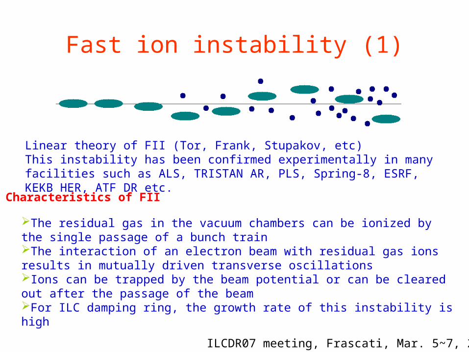
The residual gas in the vacuum chambers can be ionized by the single passage of a bunch trainThe interaction of an electron beam with residual gas ions results in mutually driven transverse oscillationsIons can be trapped by the beam potential or can be cleared out after the passage of the beamFor ILC damping ring, the growth rate of this instability is high
ILCDR07 meeting, Frascati, Mar. 5~7, 2007
Linear theory of FII (Tor, Frank, Stupakov, etc)This instability has been confirmed experimentally in many facilities such as ALS, TRISTAN AR, PLS, Spring-8, ESRF, KEKB HER, ATF DR etc.
Characteristics of FII

Fast ion instability (2)
• Linear theory of FIICritical mass
Incoherent tune shift
The exponential vertical
instability rise time
yxy
psepbcrit
rLNA
2
Tk
pCrnNQ
B
ion
yx
ebbion
i
iB
ionyebb
yxFII f
f
p
Tk
crnN
8
# ofbunches
bunchspacing
bunchintensity
critical mass
incoh. tuneshift at trainend
exponentialrise timeat train end
2625 6 ns 2.0E10 5.4 0.0037 0.005 s
5534 3 ns 1.0E10 1.4 0.0039 0.004 s
Partial pressure of CO is 0.15nTorr; one long bunch train and 30% relative ion frequency spread are assumed here
Estimation of FII in OCS6 DR
ILCDR07 meeting, Frascati, Mar. 5~7, 2007
Fast ion instability (3)
• Traditional methods to clear ions from electron beam include electrostatic electrodes, beam shaking and gaps in the bunch trains
• Clearing electrodes may increase the chamber impedance
• Beam shaking requires dedicated device to drive the ions and beam and may cause coherent transverse instabilities
• Multi-train fill pattern with regular gaps is an efficient and simple way to remedy of FII
• Bunch by bunch feedback system?
ILCDR07 meeting, Frascati, Mar. 5~7, 2007
Fast ion instability (4)
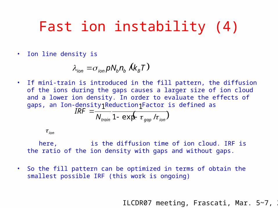
• Ion line density is
• If mini-train is introduced in the fill pattern, the diffusion of the ions during the gaps causes a larger size of ion cloud and a lower ion density. In order to evaluate the effects of gaps, an Ion-density Reduction Factor is defined as
here, is the diffusion time of ion cloud. IRF is the ratio of the ion density with gaps and without gaps.
• So the fill pattern can be optimized in terms of obtain the smallest possible IRF (this work is ongoing)
TknpN Bbbionion /
iongaptrainNIRF
/exp1
11
ILCDR07 meeting, Frascati, Mar. 5~7, 2007
ion
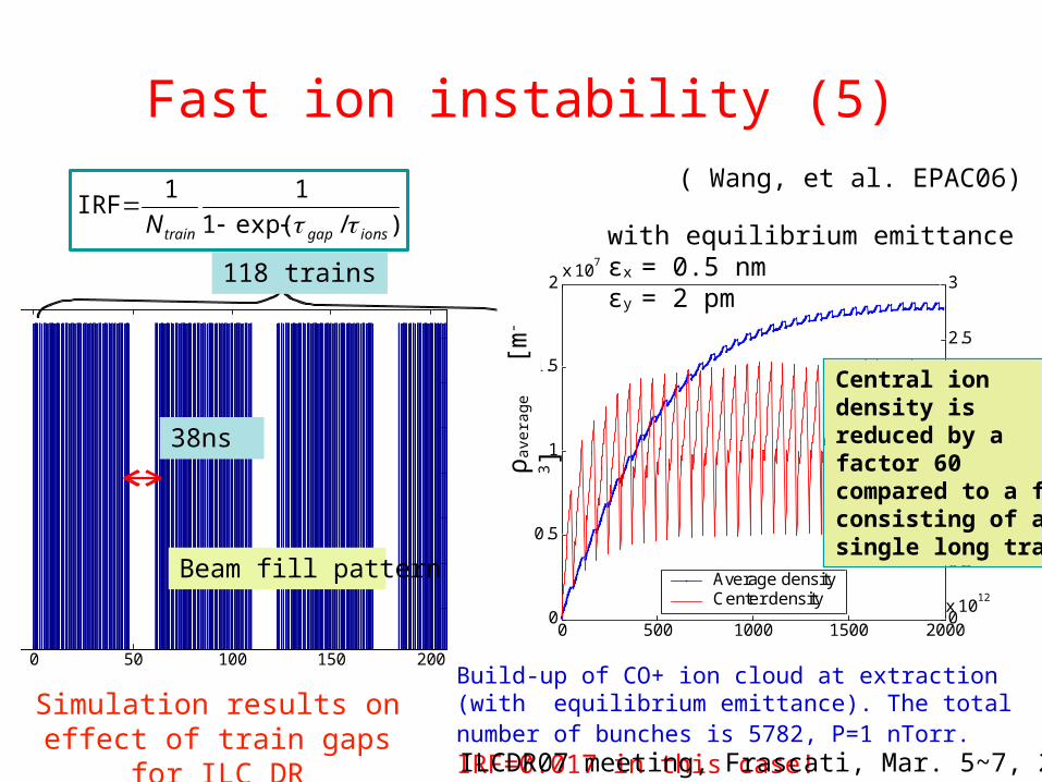
Simulation results on effect of train gaps for ILC DR
( Wang, et al. EPAC06)
0 50 100 150 200
10
20
30
40
50
60
70
Bunch ID
beam fill battern )/exp(1
11IRF
ionsgaptrainN
Beam fill pattern
38ns
118 trains
0 500 1000 1500 20000
0.5
1
1.5
2x 10
7
No. Bunches
average
(m-3)
0
0.5
1
1.5
2
2.5
3
x 1012
center
(m-3)
Average densityCenter density
Bunch ID
ρav
erag
e [
m-3]
Central iondensity isreduced by afactor 60compared to a fillconsisting of asingle long train.
Build-up of CO+ ion cloud at extraction (with equilibrium emittance). The total number of bunches is 5782, P=1 nTorr. IRF=0.017 in this case!
with equilibrium emittanceεx = 0.5 nm εy = 2 pm
ILCDR07 meeting, Frascati, Mar. 5~7, 2007
Fast ion instability (5)
Simulation of FII (1)
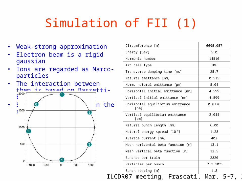
• Weak-strong approximation• Electron beam is a rigid gaussian• Ions are regarded as Marco-particles• The interaction between them is
based on Bassetti-Erskine formula• Six collision points in the ring
Circumference [m] 6695.057
Energy [GeV] 5.0
Harmonic number 14516
Arc cell type TME
Transverse damping time [ms] 25.7
Natural emittance [nm] 0.515
Norm. natural emittance [μm] 5.04
Horizontal initial emittance [nm] 4.599
Vertical initial emittance [nm] 4.599
Horizontal equilibrium emittance [nm] 0.8176
Vertical equilibrium emittance [pm] 2.044
Natural bunch length [mm] 6.00
Natural energy spread [10−3] 1.28
Average current [mA] 402
Mean horizontal beta function [m] 13.1
Mean vertical beta function [m] 12.5
Bunches per train 2820
Particles per bunch 2 x 10¹⁰
Bunch spacing [m] 1.8
ILCDR07 meeting, Frascati, Mar. 5~7, 2007
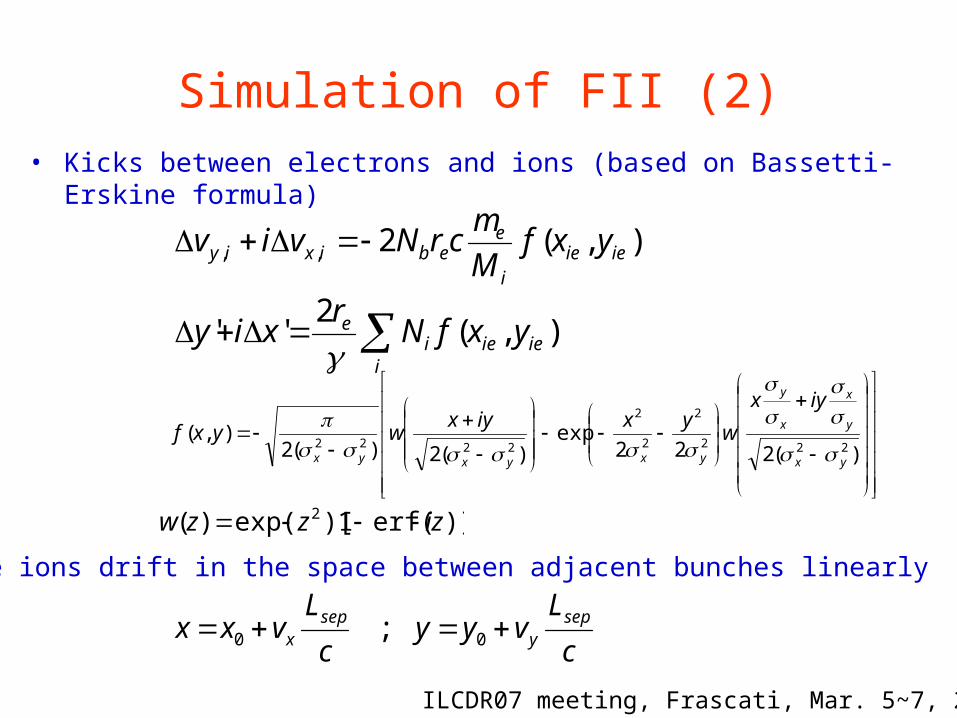
Simulation of FII (2)• Kicks between electrons and ions (based on Bassetti-Erskine formula)
)(222
exp)(2)(2
),(222
2
2
2
2222
yx
y
x
x
y
yxyxyx
iyx
wyxiyx
wyxf
),(2,, ieiei
eebixiy yxf
M
mcrNviv
i
ieieie yxfNr
xiy ),(2
''
)]erf(1)[exp()( 2 izzzw
ILCDR07 meeting, Frascati, Mar. 5~7, 2007
c
Lvyy
c
Lvxx sep
ysep
x 00 ;
• The ions drift in the space between adjacent bunches linearly
Simulation of FII (3)
),(
')sin(cossin
1cos
sin)sin(cos
' 1
1
22
1
12
21
12
21
1211
2
2
2
yxz
z
z
z
z
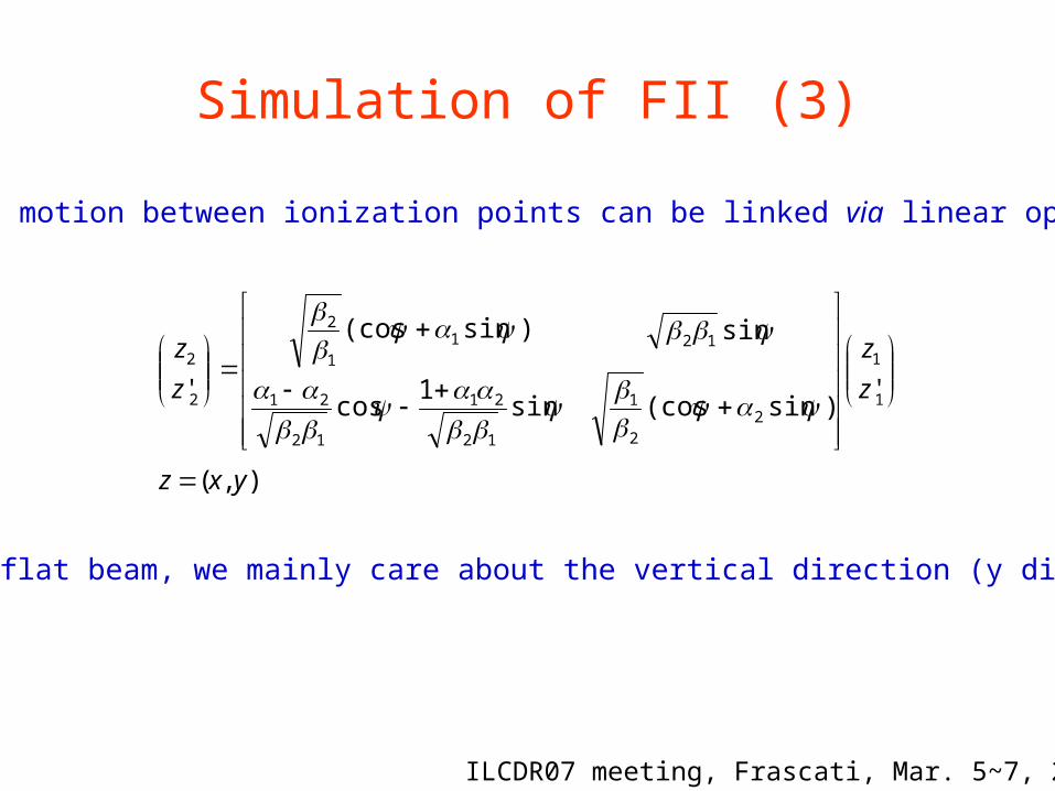
• Beam motion between ionization points can be linked via linear optics
• For the flat beam, we mainly care about the vertical direction (y direction)
ILCDR07 meeting, Frascati, Mar. 5~7, 2007
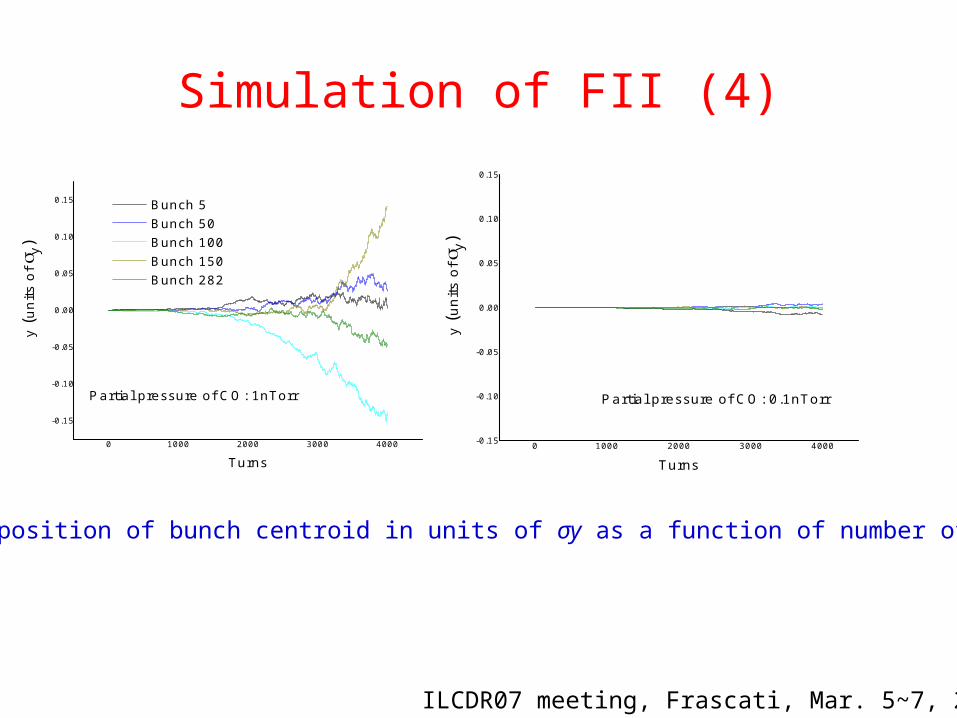
Simulation of FII (4)
0 1000 2000 3000 4000-0.15
-0.10
-0.05
0.00
0.05
0.10
0.15
y (u
nits
of
y)Turns
Partial pressure of CO: 0.1nTorr
ILCDR07 meeting, Frascati, Mar. 5~7, 2007
Vertical position of bunch centroid in units of σy as a function of number of turns
0 1000 2000 3000 4000
-0.15
-0.10
-0.05
0.00
0.05
0.10
0.15 Bunch 5 Bunch 50 Bunch 100 Bunch 150 Bunch 282
y (u
nits
of y
)
Turns
Partial pressure of CO: 1nTorr
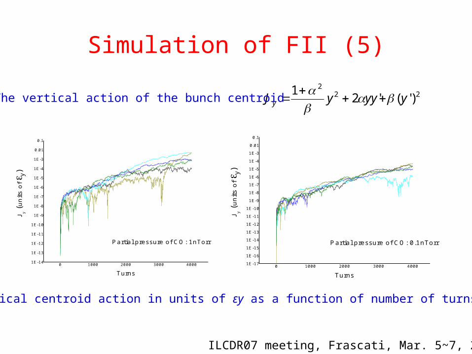
222
)'('21
yyyyJ y
0 1000 2000 3000 40001E-14
1E-13
1E-12
1E-11
1E-10
1E-9
1E-8
1E-7
1E-6
1E-5
1E-4
1E-3
0.01
0.1
J y (uni
ts o
f y
)
Turns
Partial pressure of CO: 1nTorr
The vertical action of the bunch centroid
0 1000 2000 3000 40001E-17
1E-16
1E-15
1E-14
1E-13
1E-12
1E-11
1E-10
1E-9
1E-8
1E-7
1E-6
1E-5
1E-4
1E-3
0.01
0.1
J y (un
its o
fy)
Turns
Partial pressure of CO: 0.1nTorr
Simulation of FII (5)
ILCDR07 meeting, Frascati, Mar. 5~7, 2007
Vertical centroid action in units of εy as a function of number of turns
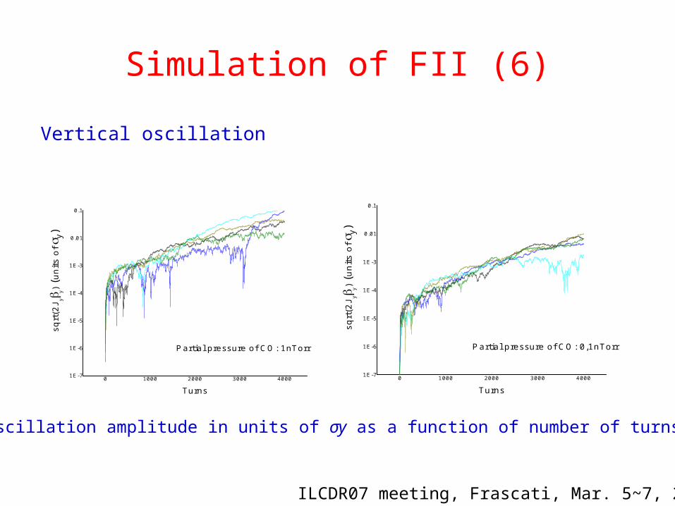
Vertical oscillation
Simulation of FII (6)
0 1000 2000 3000 40001E-7
1E-6
1E-5
1E-4
1E-3
0.01
0.1
sqrt
(2J y
y) (u
nits
of
y)
Turns
Partial pressure of CO: 1nTorr
0 1000 2000 3000 40001E-7
1E-6
1E-5
1E-4
1E-3
0.01
0.1
sqrt
(2J y
y) (u
nits
of
y)
Turns
Partial pressure of CO: 0,1nTorr
Oscillation amplitude in units of σy as a function of number of turns
ILCDR07 meeting, Frascati, Mar. 5~7, 2007
Future R&D for FII (1)
A proposal has been submitted to TB of ATF international collaboration meeting A plan on experimental studies of FII in ATF DR is ongoing (see Junji’s presentation)
Goals of FII experiment: Distinguish the two ion effects: beam size blow-up and dipole instability. Quantify the beam instability growth time, tune shift and vertical emittance
growth. Based on the linear model, the growth rate is proportional to the ion density (the related parameters include vacuum pressure, gas species, average beam line density, emittance, betatron functions and beam fill pattern).
Flatness of beam and its effect on FII growth. Quantify the bunch train gap effect Beam shaking effect Provide enough experimental data to benchmark against simulations results.
Understand of other measurements (e.g. ALS, PLS and KEKB) Check effectiveness of feedback system to suppress the FII
ILCDR07 meeting, Frascati, Mar. 5~7, 2007
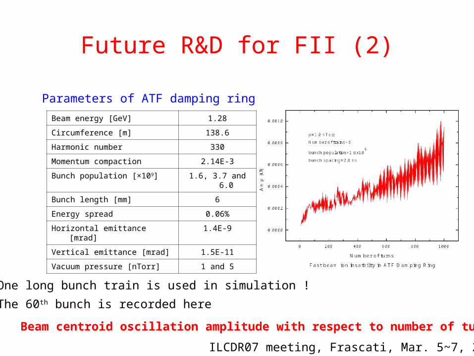
Beam centroid oscillation amplitude with respect to number of turns
One long bunch train is used in simulation !
The 60th bunch is recorded here
Beam energy [GeV] 1.28
Circumference [m] 138.6
Harmonic number 330
Momentum compaction 2.14E-3
Bunch population [×109] 1.6, 3.7 and 6.0
Bunch length [mm] 6
Energy spread 0.06%
Horizontal emittance [mrad] 1.4E-9
Vertical emittance [mrad] 1.5E-11
Vacuum pressure [nTorr] 1 and 5
Parameters of ATF damping ring
Future R&D for FII (2)
ILCDR07 meeting, Frascati, Mar. 5~7, 2007
Future R&D for FII (3)
0 200 400 600 800 1000
0.0
0.3
0.6
0.9
1.2
1.5
Am
p ()
Number of turns
Ne=1.6E9
Ne=3.7E9
Ne=6.0E9
p=5.0nTorr
number of bunches per train=20
number of bunch trains=3
bunch spacing=2.8ns
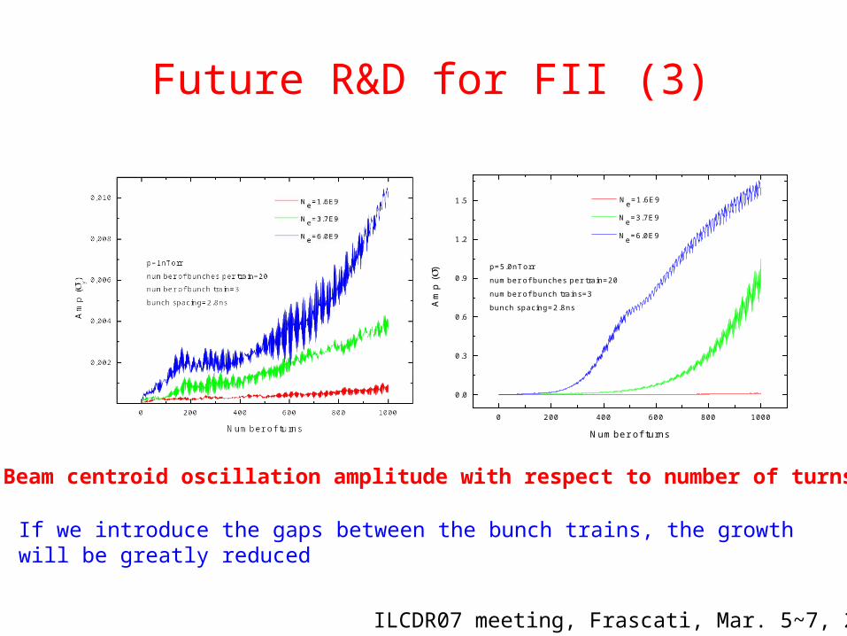
Beam centroid oscillation amplitude with respect to number of turns
If we introduce the gaps between the bunch trains, the growth will be greatly reduced
ILCDR07 meeting, Frascati, Mar. 5~7, 2007
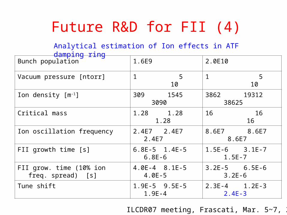
Bunch population 1.6E9 2.0E10
Vacuum pressure [ntorr] 1 5 10 1 5 10
Ion density [m-1] 309 1545 3090 3862 19312 38625
Critical mass 1.28 1.28 1.28 16 16 16
Ion oscillation frequency 2.4E7 2.4E7 2.4E7 8.6E7 8.6E7 8.6E7
FII growth time [s] 6.8E-5 1.4E-5 6.8E-6 1.5E-6 3.1E-7 1.5E-7
FII grow. time (10% ion freq. spread) [s] 4.0E-4 8.1E-5 4.0E-5 3.2E-5 6.5E-6 3.2E-6
Tune shift 1.9E-5 9.5E-5 1.9E-4 2.3E-4 1.2E-3 2.4E-3
Analytical estimation of Ion effects in ATF damping ring
Future R&D for FII (4)
ILCDR07 meeting, Frascati, Mar. 5~7, 2007
Summary
• Fast ion instability is still one of critical issues for R&D of ILCDR
• Simulation results show that this instability is within control (need further check)
• R&D of FII should be strengthened further and well coordinated around the world
• Bunch by bunch feedback systems, up-to-date vacuum technology etc. are closely related to FII
• There is an excellent opportunity to characterize FII systematically at ATF DR and to compare to simulation results
ILCDR07 meeting, Frascati, Mar. 5~7, 2007

ThanksThanks forfor youryour attentionattention !!
Linear theory
2/12/32/3
2/12/122/3
33
41
A
cLrrnNd
yxy
seppebbyiongas
c
2/12
3
4
yxysep
pbi AL
crN
rmsitraince l
c
22
11
ety /exp~
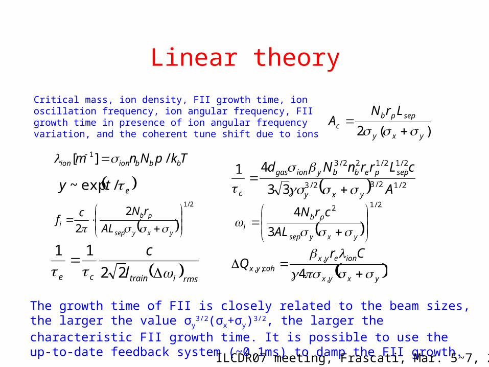
The growth time of FII is closely related to the beam sizes, the larger the value σy
3/2(σx+σy)3/2, the larger the characteristic FII growth time. It is possible to use the up-to-date feedback system (~0.1ms) to damp the FII growth.
TkpNnm bbbionion /][ 1
yxyx
ioneyxcohyx
CrQ
,
,;, 4
2/1
2
2
yxysep
pbi AL
rNcf
)(2 yxy
seppbc
LrNA
Critical mass, ion density, FII growth time, ion oscillation frequency, ion angular frequency, FII growth time in presence of ion angular frequency variation, and the coherent tune shift due to ions
ILCDR07 meeting, Frascati, Mar. 5~7, 2007

![Linux XIA: An Interoperable Meta Network Architecture to ...XIA, a native implementation of XIA [12] in the Linux ker-nel, as a candidate. We first describe Linux XIA in terms of](https://img.pdfslide.us/doc/110x75/5ee11665ad6a402d666c1866/linux-xia-an-interoperable-meta-network-architecture-to-xia-a-native-implementation.jpg)