Embed Size (px)
Citation preview
Fase # Sección IRN Tarea
A 1 COKPIT U2510005
A 1 COKPIT E2510010
A 1 COKPIT P2700050
A 1 COKPIT E2730025
A 1 COKPIT U3100001
A 1 COKPIT E5320002
A 1 ELECTRICAL E2220000
A 1 ELECTRICAL N2731061
Glareshield, Headliner, and Trim Strips - Perform General Visual Inspection. (Refer to 05-10-00.)
Crew seats and seat belts for operation, security of mounting,
and general condition.
Check for fredoom of movement of all flight controls.
Control columns (inclunding control wheels and boots) for
condition, proper operation, and clearances.
Instrument Panel - Perform General Visual Inspection. (Refer
to 05-10-00.)
Center pedestal and equioment for security and general
condition. Spoiler, throttle, and flap controls for general
condition and serviceability. Check throttle levers for proper
friction adjustment
Perform Operational Check of the Automatic Flight
Control/Stability System (AFC/SS). (Refer to 22-10-00.)
(Effective on Aircraft 25-337, 25-342 and Subsequent and prior Aircraft modified per AMK81-7 (25D/F) or AMK 81-9 (25B/C)
“Horizontal Trim and Autopilot Improvement”.)
Perform accelerometer operational check. (Effective on aircraft 25-061, 25-070 thru 25-
205, and 25-337.)
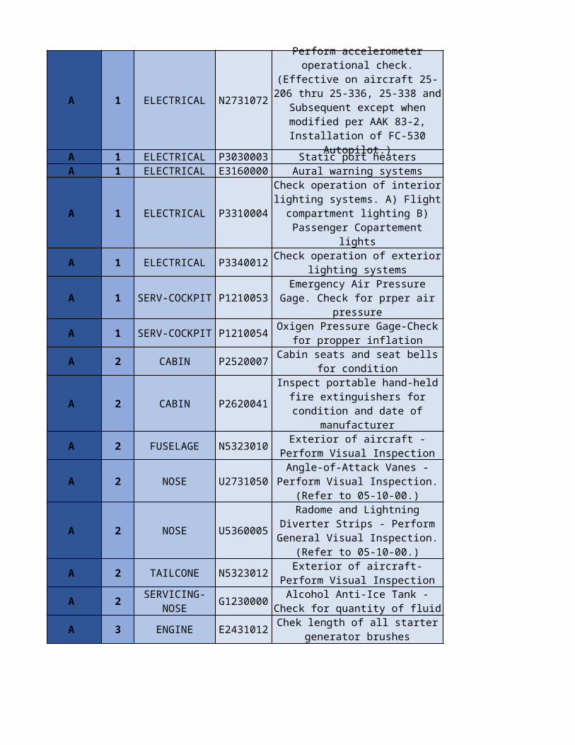
A 1 ELECTRICAL N2731072
A 1 ELECTRICAL P3030003 Static port heatersA 1 ELECTRICAL E3160000 Aural warning systems
A 1 ELECTRICAL P3310004
A 1 ELECTRICAL P3340012
A 1 SERV-COCKPIT P1210053
A 1 SERV-COCKPIT P1210054
A 2 CABIN P2520007
A 2 CABIN P2620041
A 2 FUSELAGE N5323010
A 2 NOSE U2731050
A 2 NOSE U5360005
A 2 TAILCONE N5323012
A 2 G1230000
A 3 ENGINE E2431012
Perform accelerometer operational check. (Effective on aircraft 25-206 thru 25-336, 25-
338 and Subsequent except when modified per AAK 83-2,
Installation of FC-530 Autopilot.)
Check operation of interior lighting systems. A) Flight compartment lighting B)
Passenger Copartement lights
Check operation of exterior lighting systems
Emergency Air Pressure Gage. Check for prper air pressure
Oxigen Pressure Gage-Check for propper inflation
Cabin seats and seat bells for condition
Inspect portable hand-held fire extinguishers for condition and
date of manufacturer
Exterior of aircraft - Perform Visual Inspection
Angle-of-Attack Vanes - Perform Visual Inspection. (Refer to 05-
10-00.)
Radome and Lightning Diverter Strips - Perform General Visual Inspection. (Refer to 05-10-00.)
Exterior of aircraft-Perform Visual Inspection
SERVICING-NOSE
Alcohol Anti-Ice Tank -Check for quantity of fluid
Chek length of all starter generator brushes
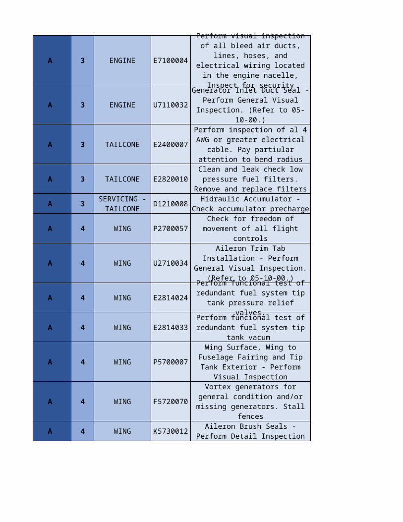
A 3 ENGINE E7100004
A 3 ENGINE U7110032
A 3 TAILCONE E2400007
A 3 TAILCONE E2820010
A 3 D1210008
A 4 WING P2700057
A 4 WING U2710034
A 4 WING E2814024
A 4 WING E2814033
A 4 WING P5700007
A 4 WING F5720070
A 4 WING K5730012
Perform visual inspection of all bleed air ducts, lines, hoses, and electrical wiring located in the
engine nacelle, Inspect for security
Generator Inlet Duct Seal - Perform General Visual
Inspection. (Refer to 05-10-00.)
Perform inspection of al 4 AWG or greater electrical cable. Pay
partiular attention to bend radius
Clean and leak check low pressure fuel filters. Remove and
replace filters
SERVICING - TAILCONE
Hidraulic Accumulator - Check accumulator precharge
Check for freedom of movement of all flight controls
Aileron Trim Tab Installation - Perform General Visual
Inspection. (Refer to 05-10-00.)
Perform funcional test of redundant fuel system tip tank
pressure relief valves.
Perform funcional test of redundant fuel system tip tank
vacum
Wing Surface, Wing to Fuselage Fairing and Tip Tank Exterior -
Perform Visual Inspection
Vortex generators for general condition and/or missing generators. Stall fences
Aileron Brush Seals - Perform Detail Inspection
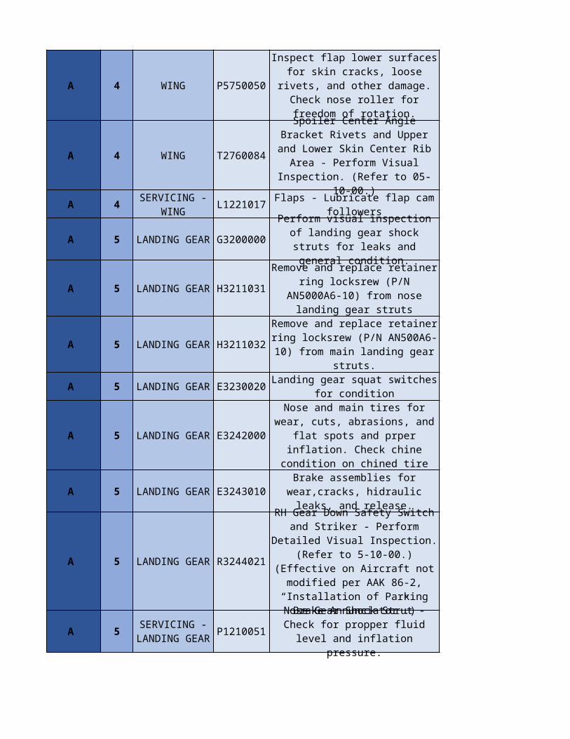
A 4 WING P5750050
A 4 WING T2760084
A 4 L1221017
A 5 LANDING GEAR G3200000
A 5 LANDING GEAR H3211031
A 5 LANDING GEAR H3211032
A 5 LANDING GEAR E3230020
A 5 LANDING GEAR E3242000
A 5 LANDING GEAR E3243010
A 5 LANDING GEAR R3244021
A 5 P1210051
Inspect flap lower surfaces for skin cracks, loose rivets, and
other damage. Check nose roller for freedom of rotation.
Spoiler Center Angle Bracket Rivets and Upper and Lower Skin Center Rib Area - Perform Visual Inspection. (Refer to 05-10-00.)
SERVICING - WING
Flaps - Lubricate flap cam followers
Perform visual inspection of landing gear shock struts for leaks and general condition.
Remove and replace retainer ring locksrew (P/N AN5000A6-10) from nose landing gear struts
Remove and replace retainer ring locksrew (P/N AN500A6-10) from
main landing gear struts.
Landing gear squat switches for condition
Nose and main tires for wear, cuts, abrasions, and flat spots
and prper inflation. Check chine condition on chined tire
Brake assemblies for wear,cracks, hidraulic leaks, and release.
RH Gear Down Safety Switch and Striker - Perform Detailed Visual Inspection. (Refer to 5-10-00.)
(Effective on Aircraft not modified per AAK 86-2,
“Installation of Parking Brake Annunciator”.)
SERVICING - LANDING GEAR
Nose Gear Shock Strut - Check for propper fluid level and
inflation pressure.
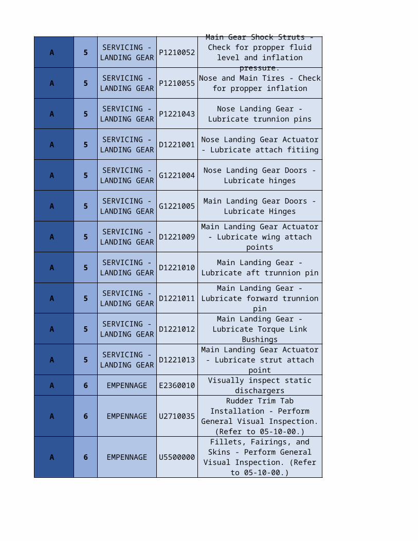
A 5 P1210052
A 5 P1210055
A 5 P1221043
A 5 D1221001
A 5 G1221004
A 5 G1221005
A 5 D1221009
A 5 D1221010
A 5 D1221011
A 5 D1221012
A 5 D1221013
A 6 EMPENNAGE E2360010 Visually inspect static dischargers
A 6 EMPENNAGE U2710035
A 6 EMPENNAGE U5500000
SERVICING - LANDING GEAR
Main Gear Shock Struts - Check for propper fluid level and
inflation pressure.
SERVICING - LANDING GEAR
Nose and Main Tires - Check for propper inflation
SERVICING - LANDING GEAR
Nose Landing Gear - Lubricate trunnion pins
SERVICING - LANDING GEAR
Nose Landing Gear Actuator - Lubricate attach fitiing
SERVICING - LANDING GEAR
Nose Landing Gear Doors - Lubricate hinges
SERVICING - LANDING GEAR
Main Landing Gear Doors - Lubricate Hinges
SERVICING - LANDING GEAR
Main Landing Gear Actuator - Lubricate wing attach points
SERVICING - LANDING GEAR
Main Landing Gear - Lubricate aft trunnion pin
SERVICING - LANDING GEAR
Main Landing Gear - Lubricate forward trunnion pin
SERVICING - LANDING GEAR
Main Landing Gear - Lubricate Torque Link Bushings
SERVICING - LANDING GEAR
Main Landing Gear Actuator - Lubricate strut attach point
Rudder Trim Tab Installation - Perform General Visual
Inspection. (Refer to 05-10-00.)
Fillets, Fairings, and Skins - Perform General Visual
Inspection. (Refer to 05-10-00.)
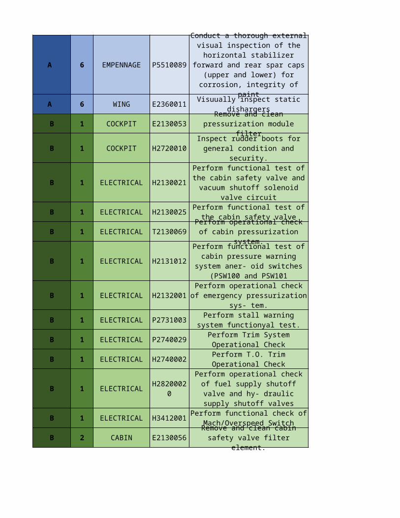
A 6 EMPENNAGE P5510089
A 6 WING E2360011 Visuually inspect static dishargers
B 1 COCKPIT E2130053
B 1 COCKPIT H2720010
B 1 ELECTRICAL H2130021
B 1 ELECTRICAL H2130025
B 1 ELECTRICAL T2130069
B 1 ELECTRICAL H2131012
B 1 ELECTRICAL H2132001
B 1 ELECTRICAL P2731003
B 1 ELECTRICAL P2740029
B 1 ELECTRICAL H2740002
B 1 ELECTRICAL
B 1 ELECTRICAL H3412001
B 2 CABIN E2130056
Conduct a thorough external visual inspection of the
horizontal stabilizer forward and rear spar caps (upper and lower) for corrosion, integrity of paint
Remove and clean pressurization module filter
Inspect rudder boots for general condition and security.
Perform functional test of the cabin safety valve and vacuum shutoff solenoid valve circuit
Perform functional test of the cabin safety valve
Perform operational check of cabin pressurization system.
Perform functional test of cabin pressure warning system aner-
oid switches (PSW100 and PSW101
Perform operational check of emergency pressurization sys-
tem.
Perform stall warning system functionyal test.
Perform Trim System Operational Check
Perform T.O. Trim Operational Check
H28200020
Perform operational check of fuel supply shutoff valve and hy- draulic supply shutoff valves
Perform functional check of Mach/Overspeed Switch
Remove and clean cabin safety valve filter element.
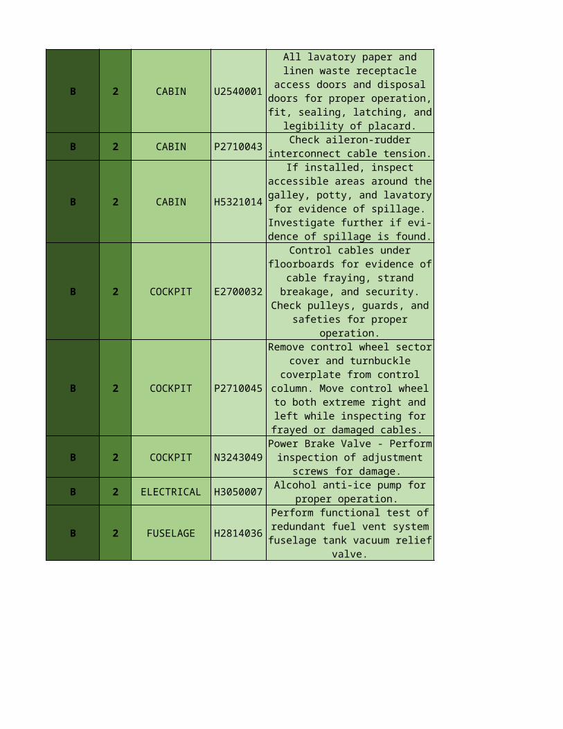
B 2 CABIN
B 2 CABIN P2710043
B 2 CABIN H5321014
B 2 COCKPIT E2700032
B 2 COCKPIT P2710045
B 2 COCKPIT N3243049
B 2 ELECTRICAL H3050007
B 2 FUSELAGE H2814036
U2540001
All lavatory paper and linen waste receptacle access doors and disposal doors for proper
operation, fit, sealing, latching, and legibility of placard.
Check aileron-rudder interconnect cable tension.
If installed, inspect accessible areas around the galley, potty,
and lavatory for evidence of spillage. Investigate further if evi-
dence of spillage is found.
Control cables under floorboards for evidence of cable fraying,
strand breakage, and security. Check pulleys, guards, and
safeties for proper operation.
Remove control wheel sector cover and turnbuckle coverplate
from control column. Move control wheel to both extreme
right and left while inspecting for frayed or damaged cables.
Power Brake Valve - Perform inspection of adjustment screws
for damage.
Alcohol anti-ice pump for proper operation.
Perform functional test of redundant fuel vent system fuselage tank vacuum relief
valve.
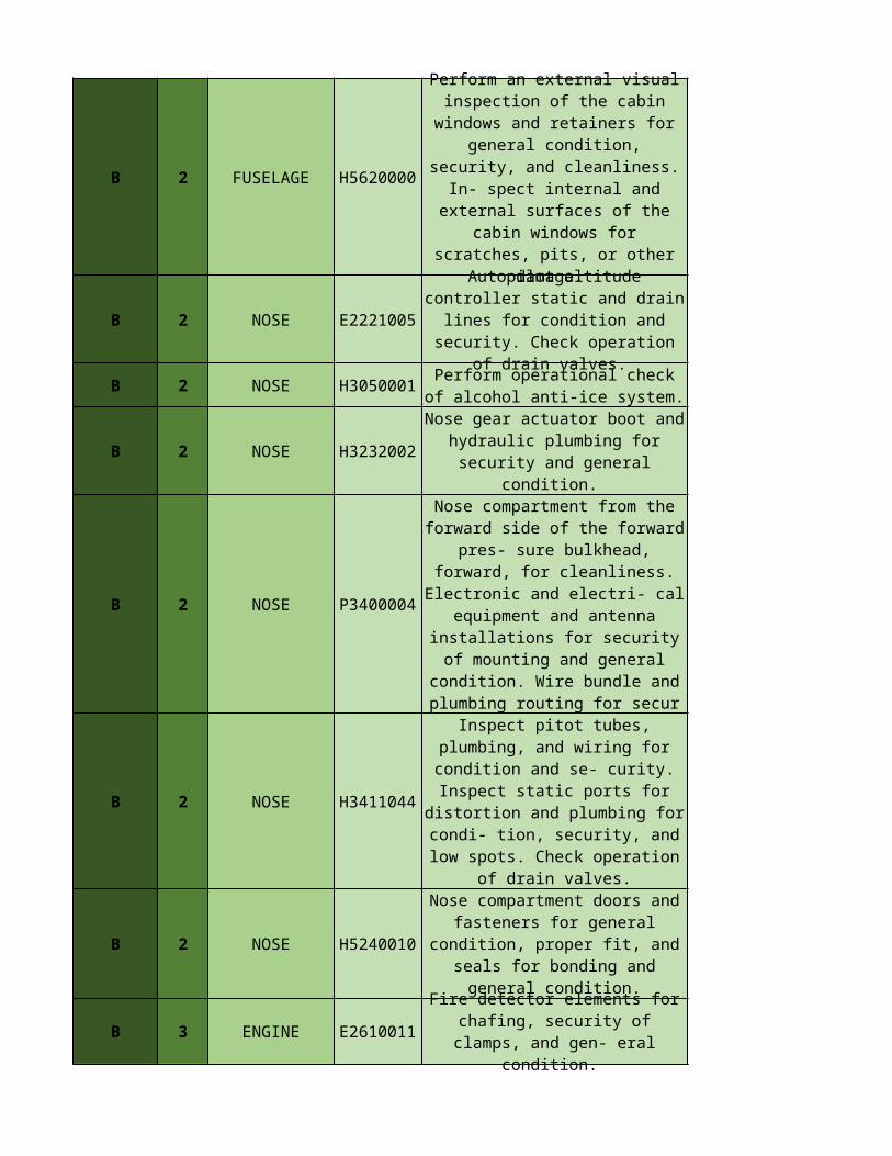
B 2 FUSELAGE H5620000
B 2 NOSE E2221005
B 2 NOSE H3050001
B 2 NOSE H3232002
B 2 NOSE P3400004
B 2 NOSE H3411044
B 2 NOSE H5240010
B 3 ENGINE E2610011
Perform an external visual inspection of the cabin windows
and retainers for general condition, security, and
cleanliness. In- spect internal and external surfaces of the cabin windows for scratches, pits, or
other damage.
Autopilot altitude controller static and drain lines for
condition and security. Check operation of drain valves.
Perform operational check of alcohol anti-ice system.
Nose gear actuator boot and hydraulic plumbing for security
and general condition.
Nose compartment from the forward side of the forward pres-
sure bulkhead, forward, for cleanliness. Electronic and electri- cal equipment and
antenna installations for security of mounting and general
condition. Wire bundle and plumbing routing for secur
Inspect pitot tubes, plumbing, and wiring for condition and se-
curity. Inspect static ports for distortion and plumbing for
condi- tion, security, and low spots. Check operation of drain
valves.
Nose compartment doors and fasteners for general condition, proper fit, and seals for bonding
and general condition.
Fire detector elements for chafing, security of clamps, and
gen- eral condition.
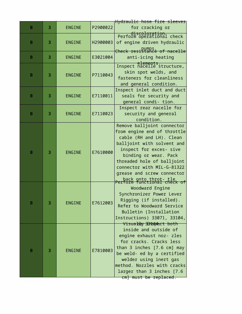
B 3 ENGINE P2900022
B 3 ENGINE H2900003
B 3 ENGINE E3021004
B 3 ENGINE P7110043
B 3 ENGINE E7110011
B 3 ENGINE E7110023
B 3 ENGINE E7610000
B 3 ENGINE E7612003
B 3 ENGINE E7810003
Hydraulic hose fire sleeves for cracking or discoloration.
Perform operational check of engine driven hydraulic pumps.
Check resistance of nacelle anti-icing heating elements.
Inspect nacelle structure, skin spot welds, and fasteners for
cleanliness and general condition.
Inspect inlet duct and duct seals for security and general condi-
tion.
Inspect rear nacelle for security and general condition.
Remove balljoint connector from engine end of throttle cable (RH
and LH). Clean balljoint with solvent and inspect for exces-
sive binding or wear. Pack threaded hole of balljoint
connector with MIL-G-81322 grease and screw connector back
onto throt- tle
Perform functional check of Woodward Engine Synchronizer
Power Lever Rigging (if installed). Refer to Woodward Service
Bulletin (Installation Instructions) 33071, 33104, or 33144.
Visually inspect both inside and outside of engine exhaust noz-
zles for cracks. Cracks less than 3 inches [7.6 cm] may be weld- ed by a certified welder using inert gas method. Nozzles with cracks
larger than 3 inches [7.6 cm] must be replaced.
B 3 TAILCONE H2150000
B 3 TAILCONE E2150001
B 3 TAILCONE H2160005
B 3 TAILCONE
B 3 TAILCONE E2700031
B 3 TAILCONE E2431042
B 3 TAILCONE P2910022
B 3 TAILCONE E2910004
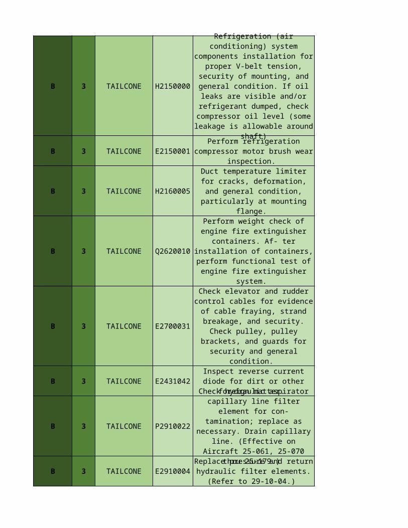
Refrigeration (air conditioning) system components installation
for proper V-belt tension, security of mounting, and
general condition. If oil leaks are visible and/or refrigerant
dumped, check compressor oil level (some leakage is allowable
around shaft)
Perform refrigeration compressor motor brush wear inspection.
Duct temperature limiter for cracks, deformation, and general
condition, particularly at mounting flange.
Q2620010
Perform weight check of engine fire extinguisher containers. Af-
ter installation of containers, perform functional test of engine
fire extinguisher system.
Check elevator and rudder control cables for evidence of
cable fraying, strand breakage, and security. Check pulley, pulley brackets, and guards for security
and general condition.
Inspect reverse current diode for dirt or other foreign matter.
Check hydraulic aspirator capillary line filter element for
con- tamination; replace as necessary. Drain capillary line.
(Effective on Aircraft 25-061, 25-070 thru 25-179.)
Replace pressure and return hydraulic filter elements. (Refer
to 29-10-04.)
B 3 TAILCONE
B 3 TAILCONE E5450001
B 4 WING H2700018
B 4 WING E2700033
B 4 WING
B 4 WING P2760003
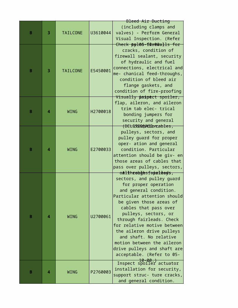
U3610044 Bleed Air Ducting (including
clamps and valves) - Perform General Visual Inspection. (Refer
to 05-10-00.)
Check pylon firewalls for cracks, condition of firewall sealant, security of hydraulic and fuel
connections, electrical and me- chanical feed-throughs, condition
of bleed air flange gaskets, and condition of fire-proofing paint.
Visually inspect spoiler, flap, aileron, and aileron trim tab elec-
trical bonding jumpers for security and general condition.
(DELETED)All cables, pulleys, sectors, and pulley guard for
proper oper- ation and general condition. Particular attention
should be giv- en those areas of cables that pass over pulleys, sectors, or through fairleads.
U2700061
All cables, pulleys, sectors, and pulley guard for proper operationand general condition. Particular attention should be given those areas of cables that pass over
pulleys, sectors, or through fairleads. Check for relative
motive between the aileron drive pulleys and shaft. No relative
motion between the aileron drive pulleys and shaft are acceptable.
(Refer to 05-10-00.)
Inspect spoiler actuator installation for security, support struc- ture cracks, and general
condition.
B 4 WING V2812000
B 4 WING E2812050
B 4 WING E5720010
B 4 WING E5770013
B 4 G1221016
B 5 P2400008
B 5 P2700054
B 5 LANDING GEAR H3230000
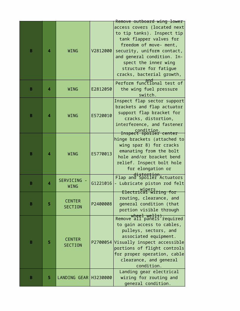
Remove outboard wing lower access covers (located next to tip
tanks). Inspect tip tank flapper valves for freedom of move-
ment, security, uniform contact, and general condition. In- spect
the inner wing structure for fatigue cracks, bacterial growth,
and
Perform functional test of the wing fuel pressure switch.
Inspect flap sector support brackets and flap actuator
support flap bracket for cracks, distortion, interference, and
fastener condition.
Inspect spoiler center hinge brackets (attached to wing spar
8) for cracks emanating from the bolt hole and/or bracket bend
relief. Inspect bolt hole for elongation or distortion.
SERVICING - WING
Flap and Spoiler Actuators - Lubricate piston rod felt wipers.
CENTER SECTION
Electrical wiring for routing, clearance, and general condition
(that portion visible through wheel wells).
CENTER SECTION
Remove all panels required to gain access to cables, pulleys,
sectors, and associated equipment. Visually inspect accessible portions of flight
controls for proper operation, cable clearance, and general
condition.
Landing gear electrical wiring for routing and general condition.
B 5 LANDING GEAR H3243000
B 5 LANDING GEAR E3244020
B 5 D1221002
B 5 G1221007
B 5 F1221008
B 5 D1221014
B 6 CABIN H5210060
B 6 EMPENNAGE G2211043
B 6 EMPENNAGE P2700055
B 6 EMPENNAGE T2700056
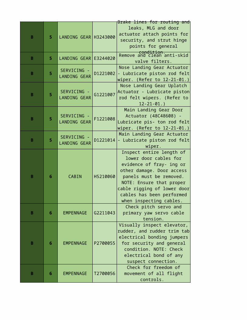
Brake lines for routing and leaks, MLG and door actuator attach points for security, and strut
hinge points for general condition.
Remove and clean anti-skid valve filters.
SERVICING - LANDING GEAR
Nose Landing Gear Actuator - Lubricate piston rod felt wiper.
(Refer to 12-21-01.)
SERVICING - LANDING GEAR
Nose Landing Gear Uplatch Actuator - Lubricate piston rod
felt wipers. (Refer to 12-21-01.)
SERVICING - LANDING GEAR
Main Landing Gear Door Actuator (48C48608) - Lubricate pis- ton rod felt wiper. (Refer to 12-21-
01.)
SERVICING - LANDING GEAR
Main Landing Gear Actuator - Lubricate piston rod felt wiper.
Inspect entire length of lower door cables for evidence of fray- ing or other damage. Door access panels must be removed. NOTE: Ensure that proper cable rigging of lower door cables has been
performed when inspecting cables.
Check pitch servo and primary yaw servo cable tension.
Visually inspect elevator, rudder, and rudder trim tab electrical
bonding jumpers for security and general condition. NOTE: Check electrical bond of any suspect
connection.
Check for freedom of movement of all flight controls.
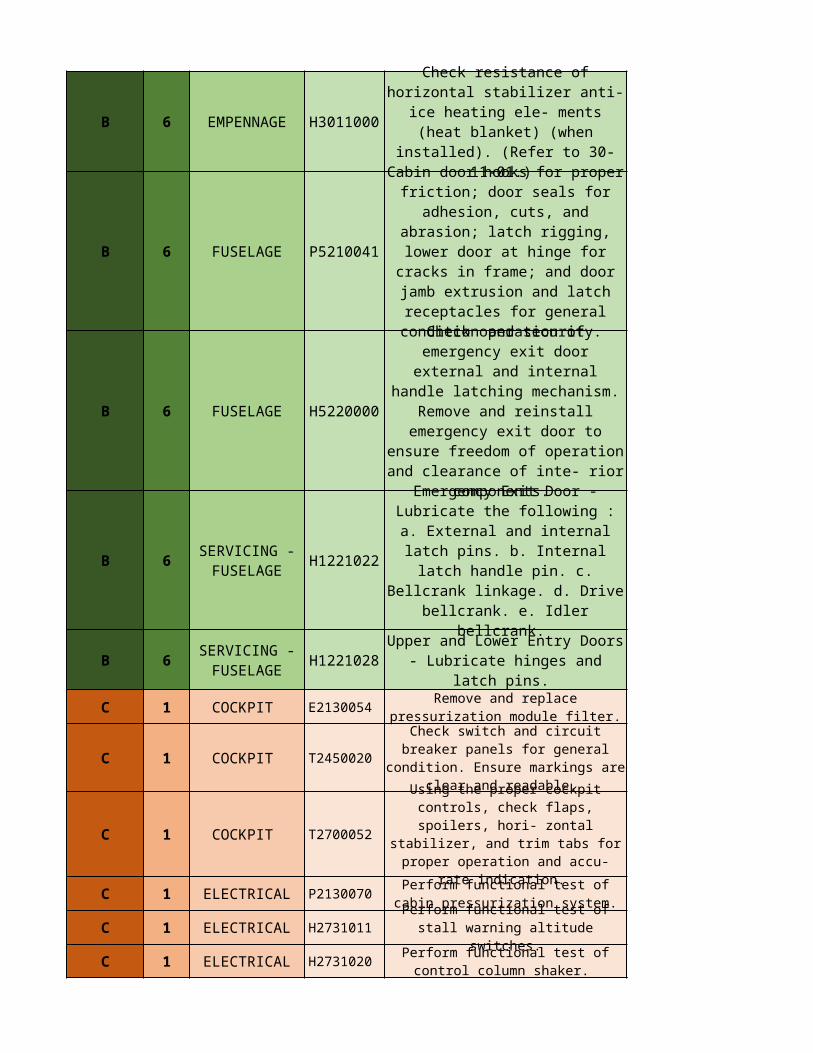
B 6 EMPENNAGE H3011000
B 6 FUSELAGE P5210041
B 6 FUSELAGE H5220000
B 6 H1221022
B 6 H1221028
C 1 COCKPIT
C 1 COCKPIT
C 1 COCKPIT
C 1 ELECTRICAL
C 1 ELECTRICAL
C 1 ELECTRICAL
Check resistance of horizontal stabilizer anti-ice heating ele- ments (heat blanket) (when
installed). (Refer to 30-11-01.)
Cabin door hooks for proper friction; door seals for adhesion, cuts, and abrasion; latch rigging, lower door at hinge for cracks in frame; and door jamb extrusion and latch receptacles for general
condition and security.
Check operation of emergency exit door external and internal
handle latching mechanism. Remove and reinstall emergency exit door to ensure freedom of
operation and clearance of inte- rior components.
SERVICING - FUSELAGE
Emergency Exit Door - Lubricate the following : a. External and internal latch pins. b. Internal latch handle pin. c. Bellcrank linkage. d. Drive bellcrank. e.
Idler bellcrank.
SERVICING - FUSELAGE
Upper and Lower Entry Doors - Lubricate hinges and latch pins.
E2130054
Remove and replace pressurization module filter.
T2450020
Check switch and circuit breaker panels for general condition. Ensure markings
are clear and readable.
T2700052
Using the proper cockpit controls, check flaps, spoilers, hori- zontal
stabilizer, and trim tabs for proper operation and accu-
rate indication. P213007
0 Perform functional test of
cabin pressurization system.H273101
1
Perform functional test of stall warning altitude
switches.H273102
0 Perform functional test of control column shaker.
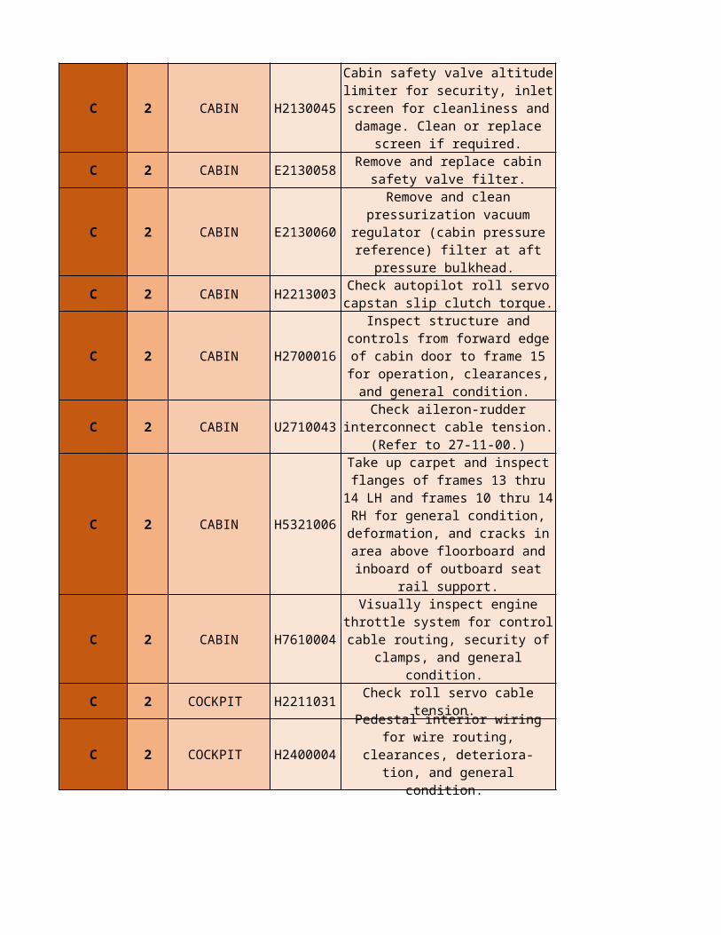
C 2 CABIN H2130045
C 2 CABIN E2130058
C 2 CABIN E2130060
C 2 CABIN H2213003
C 2 CABIN H2700016
C 2 CABIN U2710043
C 2 CABIN H5321006
C 2 CABIN H7610004
C 2 COCKPIT H2211031 Check roll servo cable tension.
C 2 COCKPIT H2400004
Cabin safety valve altitude limiter for security, inlet screen for
cleanliness and damage. Clean or replace screen if required.
Remove and replace cabin safety valve filter.
Remove and clean pressurization vacuum regulator (cabin pressure
reference) filter at aft pressure bulkhead.
Check autopilot roll servo capstan slip clutch torque.
Inspect structure and controls from forward edge of cabin door
to frame 15 for operation, clearances, and general
condition.
Check aileron-rudder interconnect cable tension.
(Refer to 27-11-00.)
Take up carpet and inspect flanges of frames 13 thru 14 LH and frames 10 thru 14 RH for
general condition, deformation, and cracks in area above
floorboard and inboard of outboard seat rail support.
Visually inspect engine throttle system for control cable routing, security of clamps, and general
condition.
Pedestal interior wiring for wire routing, clearances, deteriora- tion, and general condition.
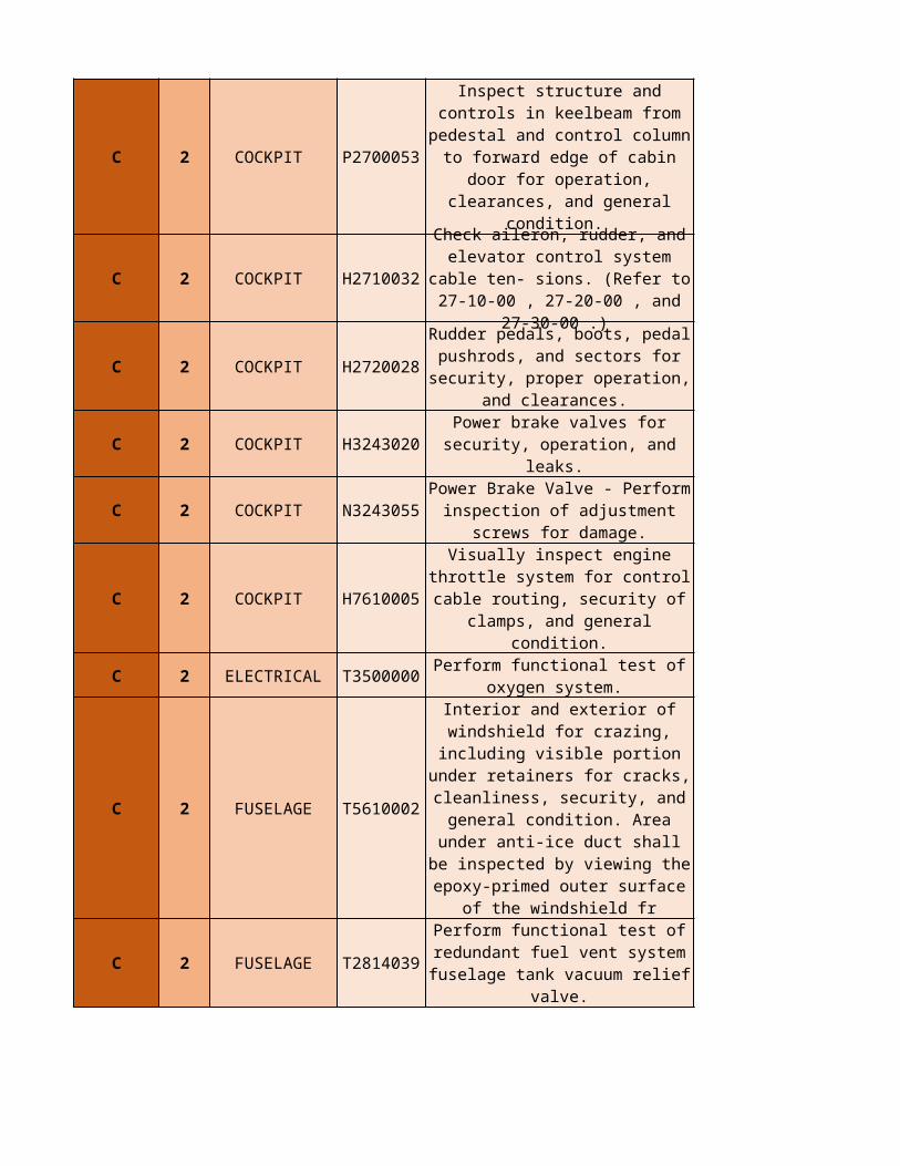
C 2 COCKPIT P2700053
C 2 COCKPIT H2710032
C 2 COCKPIT H2720028
C 2 COCKPIT H3243020
C 2 COCKPIT
C 2 COCKPIT H7610005
C 2 ELECTRICAL T3500000
C 2 FUSELAGE T5610002
C 2 FUSELAGE T2814039
Inspect structure and controls in keelbeam from pedestal and
control column to forward edge of cabin door for operation,
clearances, and general condition.
Check aileron, rudder, and elevator control system cable ten- sions. (Refer to 27-10-00 ,
27-20-00 , and 27-30-00 .)
Rudder pedals, boots, pedal pushrods, and sectors for
security, proper operation, and clearances.
Power brake valves for security, operation, and leaks.
N3243055 Power Brake Valve - Perform
inspection of adjustment screws for damage.
Visually inspect engine throttle system for control cable routing, security of clamps, and general
condition.
Perform functional test of oxygen system.
Interior and exterior of windshield for crazing, including visible portion under retainers for cracks, cleanliness, security,
and general condition. Area under anti-ice duct shall be
inspected by viewing the epoxy-primed outer surface of the
windshield fr
Perform functional test of redundant fuel vent system fuselage tank vacuum relief
valve.
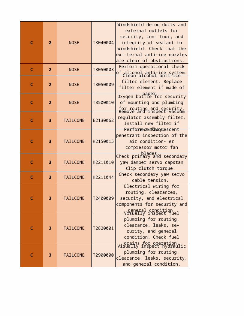
C 2 NOSE T3040004
C 2 NOSE T3050003
C 2 NOSE T3050009
C 2 NOSE T3500010
C 3 TAILCONE E2130062
C 3 TAILCONE H2150015
C 3 TAILCONE H2211010
C 3 TAILCONE H2211044
C 3 TAILCONE T2400009
C 3 TAILCONE T2820001
C 3 TAILCONE T2900000
Windshield defog ducts and external outlets for security, con- tour, and integrity of sealant to windshield. Check that the ex-
ternal anti-ice nozzles are clear of obstructions.
Perform operational check of alcohol anti-ice system.
Clean alcohol anti-ice filter element. Replace filter element if
made of paper.
Oxygen bottle for security of mounting and plumbing for
routing and security.
Remove and inspect vacuum regulator assembly filter. Install
new filter if necessary.
Perform a fluorescent penetrant inspection of the air condition- er
compressor motor fan blades.
Check primary and secondary yaw damper servo capstan slip
clutch torque.
Check secondary yaw servo cable tension.
Electrical wiring for routing, clearances, security, and electrical components for
security and general condition.
Visually inspect fuel plumbing for routing, clearance, leaks, se- curity, and general condition.
Check fuel drains for operation.
Visually inspect hydraulic plumbing for routing, clearance,
leaks, security, and general condition.
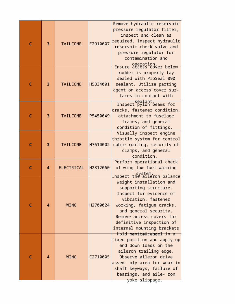
C 3 TAILCONE E2910007
C 3 TAILCONE H5334001
C 3 TAILCONE P5450049
C 3 TAILCONE H7610002
C 4 ELECTRICAL H2812060
C 4 WING H2700024
C 4 WING E2710005
Remove hydraulic reservoir pressure regulator filter, inspect and clean as required. Inspect hydraulic reservoir check valve
and pressure regulator for contamination and operation.
Ensure access cover below rudder is properly fay sealed with
ProSeal 890 sealant. Utilize parting agent on access cover
sur- faces in contact with sealant.
Inspect pylon beams for cracks, fastener condition, attachment to fuselage frames, and general
condition of fittings.
Visually inspect engine throttle system for control cable routing, security of clamps, and general
condition.
Perform operational check of wing low fuel warning system.
Inspect the aileron balance weight installation and
supporting structure. Inspect for evidence of vibration, fastener
working, fatigue cracks, and general security. Remove access
covers for definitive inspection of internal mounting brackets or
structure.
Hold control wheel in a fixed position and apply up and down
loads on the aileron trailing edge. Observe aileron drive assem- bly area for wear in shaft keyways, failure of bearings, and aile- ron
yoke slippage.
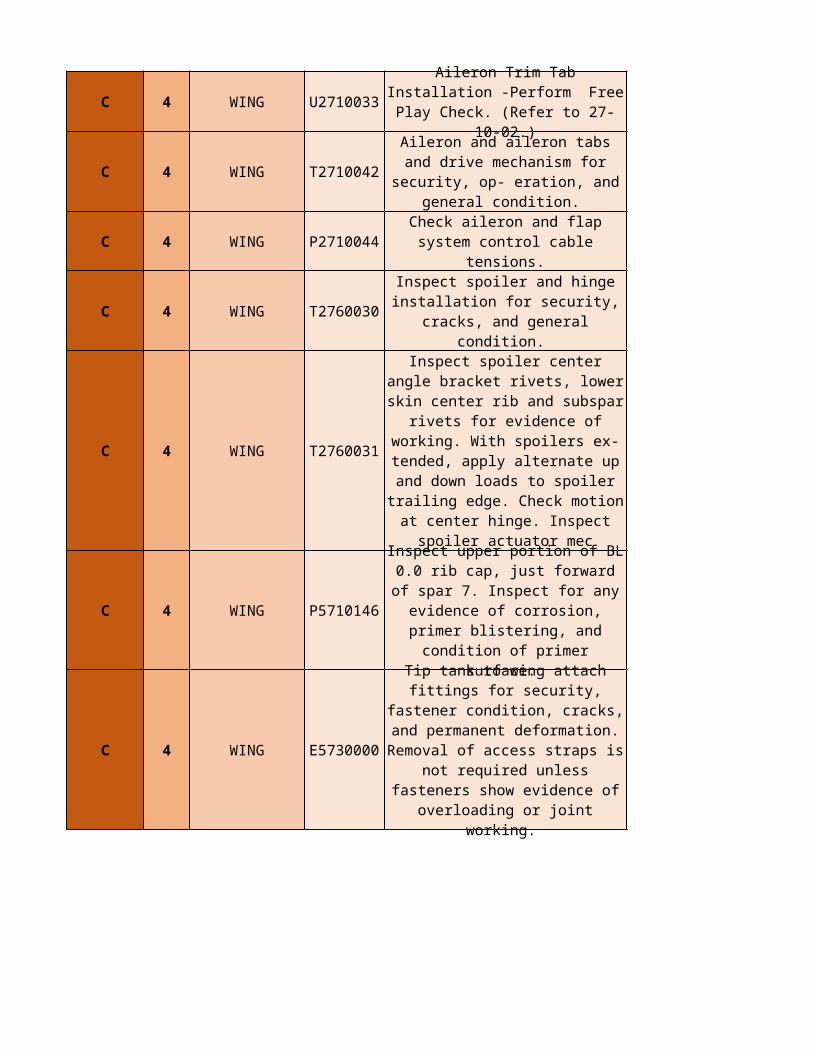
C 4 WING
C 4 WING T2710042
C 4 WING P2710044
C 4 WING T2760030
C 4 WING T2760031
C 4 WING P5710146
C 4 WING E5730000
U2710033 Aileron Trim Tab Installation -
Perform Free Play Check. (Refer to 27-10-02.)
Aileron and aileron tabs and drive mechanism for security, op- eration, and general condition.
Check aileron and flap system control cable tensions.
Inspect spoiler and hinge installation for security, cracks,
and general condition.
Inspect spoiler center angle bracket rivets, lower skin center
rib and subspar rivets for evidence of working. With spoilers ex- tended, apply
alternate up and down loads to spoiler trailing edge. Check
motion at center hinge. Inspect spoiler actuator mec
Inspect upper portion of BL 0.0 rib cap, just forward of spar 7.
Inspect for any evidence of corrosion, primer blistering, and
condition of primer surface.
Tip tank to wing attach fittings for security, fastener condition,
cracks, and permanent deformation. Removal of access
straps is not required unless fasteners show evidence of
overloading or joint working.
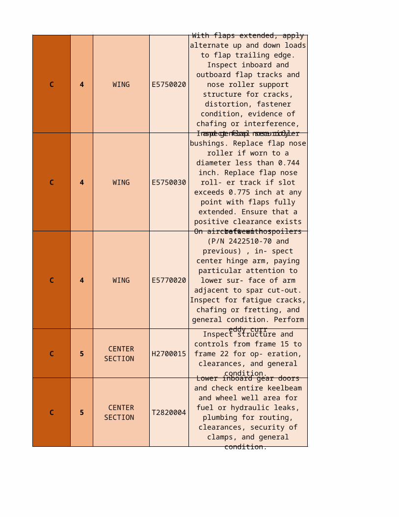
C 4 WING E5750020
C 4 WING E5750030
C 4 WING E5770020
C 5 H2700015
C 5 T2820004
With flaps extended, apply alternate up and down loads to
flap trailing edge. Inspect inboard and outboard flap tracks and
nose roller support structure for cracks, distortion, fastener
condition, evidence of chafing or interference, and general
security.
Inspect flap nose roller bushings. Replace flap nose roller if worn to a diameter less than 0.744 inch. Replace flap nose roll- er
track if slot exceeds 0.775 inch at any point with flaps fully
extended. Ensure that a positive clearance exists between nos
On aircraft with spoilers (P/N 2422510-70 and previous) , in- spect center hinge arm, paying
particular attention to lower sur- face of arm adjacent to spar cut-
out. Inspect for fatigue cracks, chafing or fretting, and general condition. Perform eddy curr
CENTER SECTION
Inspect structure and controls from frame 15 to frame 22 for
op- eration, clearances, and general condition.
CENTER SECTION
Lower inboard gear doors and check entire keelbeam and wheel
well area for fuel or hydraulic leaks, plumbing for routing,
clearances, security of clamps, and general condition.
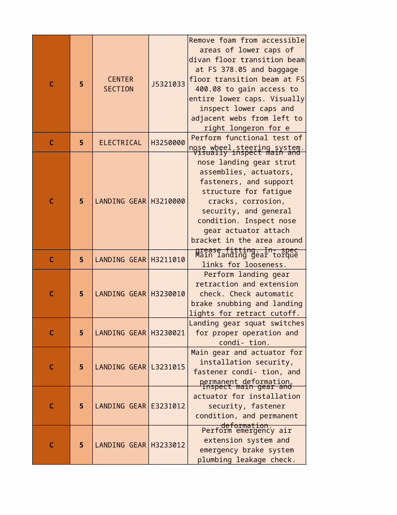
C 5 J5321033
C 5 ELECTRICAL H3250000
C 5 H3210000
C 5 H3211010
C 5 H3230010
C 5 H3230021
C 5 L3231015
C 5 E3231012
C 5 H3233012
CENTER SECTION
Remove foam from accessible areas of lower caps of divan floor transition beam at FS 378.05 and baggage floor transition beam at FS 400.08 to gain access to entire lower caps. Visually inspect lower caps and adjacent webs from left
to right longeron for e
Perform functional test of nose wheel steering system.
LANDING GEAR
Visually inspect main and nose landing gear strut assemblies,
actuators, fasteners, and support structure for fatigue cracks,
corrosion, security, and general condition. Inspect nose gear
actuator attach bracket in the area around grease fitting. In-
spec
LANDING GEAR Main landing gear torque links for looseness.
LANDING GEAR Perform landing gear retraction
and extension check. Check automatic brake snubbing and
landing lights for retract cutoff.
LANDING GEAR Landing gear squat switches for proper operation and condi- tion.
LANDING GEAR Main gear and actuator for
installation security, fastener condi- tion, and permanent
deformation.
LANDING GEAR Inspect main gear and actuator
for installation security, fastener condition, and permanent
deformation.
LANDING GEAR Perform emergency air extension
system and emergency brake system plumbing leakage check.
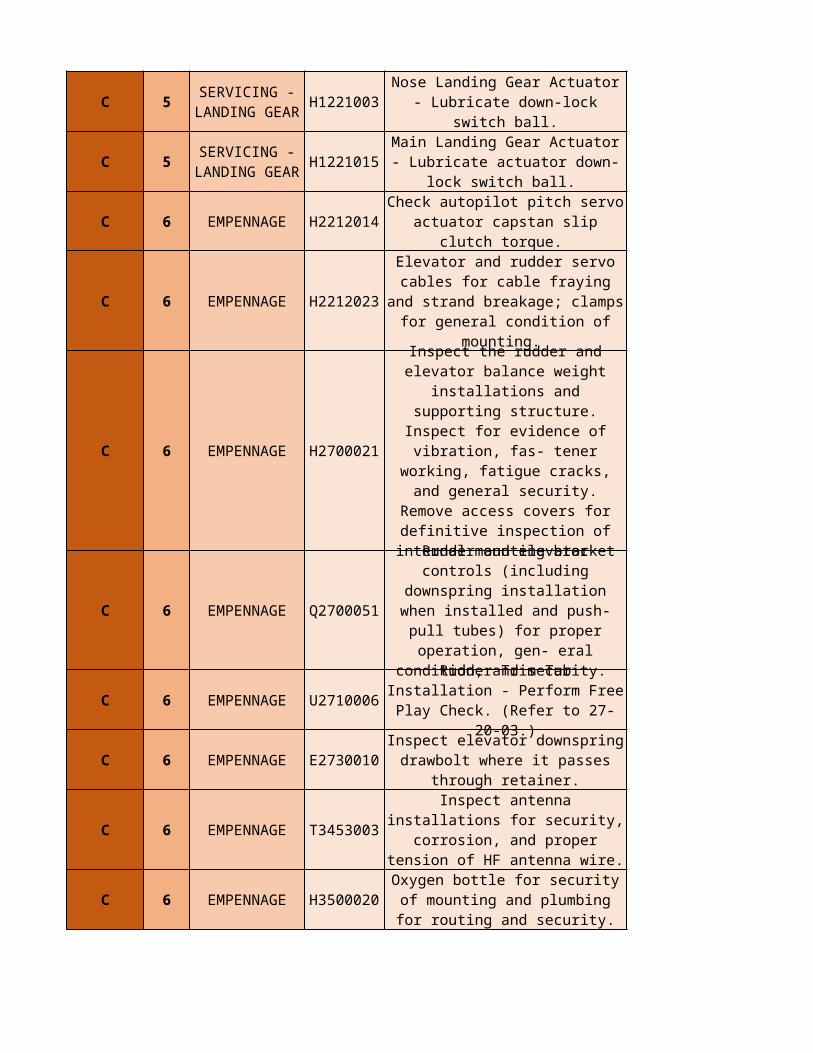
C 5 H1221003
C 5 H1221015
C 6 EMPENNAGE H2212014
C 6 EMPENNAGE H2212023
C 6 EMPENNAGE H2700021
C 6 EMPENNAGE
C 6 EMPENNAGE
C 6 EMPENNAGE E2730010
C 6 EMPENNAGE T3453003
C 6 EMPENNAGE H3500020
SERVICING - LANDING GEAR
Nose Landing Gear Actuator - Lubricate down-lock switch ball.
SERVICING - LANDING GEAR
Main Landing Gear Actuator - Lubricate actuator down-lock
switch ball.
Check autopilot pitch servo actuator capstan slip clutch
torque.
Elevator and rudder servo cables for cable fraying and strand
breakage; clamps for general condition of mounting.
Inspect the rudder and elevator balance weight installations and supporting structure. Inspect for evidence of vibration, fas- tener
working, fatigue cracks, and general security. Remove access
covers for definitive inspection of internal mounting bracket
Q2700051
Rudder and elevator controls (including downspring
installation when installed and push-pull tubes) for proper
operation, gen- eral condition, and security.
U2710006 Rudder Trim Tab Installation -
Perform Free Play Check. (Refer to 27-20-03.)
Inspect elevator downspring drawbolt where it passes through
retainer.
Inspect antenna installations for security, corrosion, and proper
tension of HF antenna wire.
Oxygen bottle for security of mounting and plumbing for
routing and security.
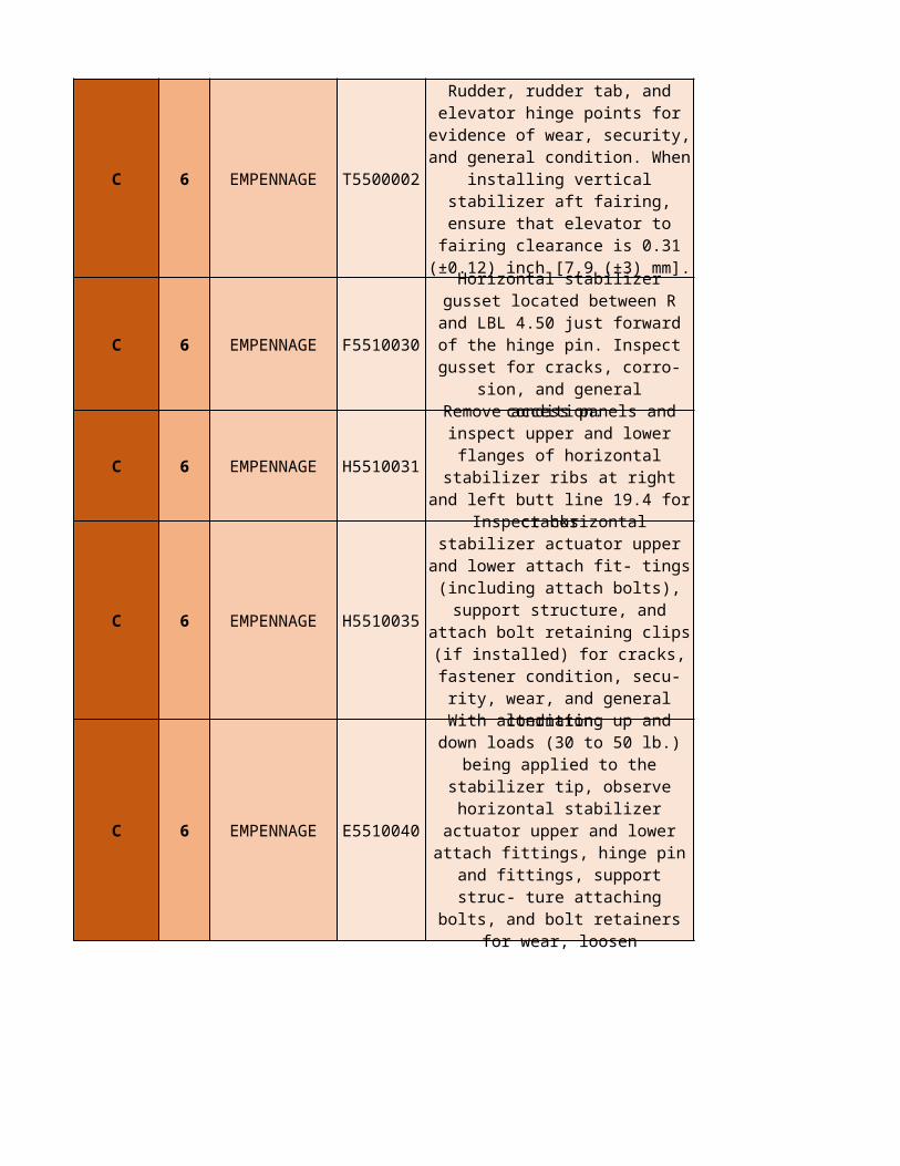
C 6 EMPENNAGE T5500002
C 6 EMPENNAGE F5510030
C 6 EMPENNAGE H5510031
C 6 EMPENNAGE H5510035
C 6 EMPENNAGE E5510040
Rudder, rudder tab, and elevator hinge points for evidence of wear, security, and general condition. When installing
vertical stabilizer aft fairing, ensure that elevator to fairing
clearance is 0.31 (±0.12) inch [7.9 (±3) mm].
Horizontal stabilizer gusset located between R and LBL 4.50
just forward of the hinge pin. Inspect gusset for cracks, corro-
sion, and general condition.
Remove access panels and inspect upper and lower flanges
of horizontal stabilizer ribs at right and left butt line 19.4 for
cracks.
Inspect horizontal stabilizer actuator upper and lower attach fit- tings (including attach bolts),
support structure, and attach bolt retaining clips (if installed) for cracks, fastener condition, secu- rity, wear, and general
condition.
With alternating up and down loads (30 to 50 lb.) being applied
to the stabilizer tip, observe horizontal stabilizer actuator
upper and lower attach fittings, hinge pin and fittings, support struc- ture attaching bolts, and bolt retainers for wear, loosen
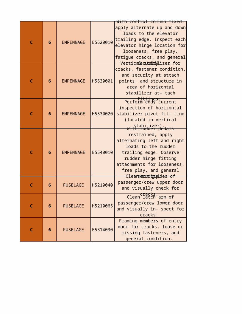
C 6 EMPENNAGE E5520010
C 6 EMPENNAGE H5530001
C 6 EMPENNAGE H5530020
C 6 EMPENNAGE E5540010
C 6 FUSELAGE H5210040
C 6 FUSELAGE H5210065
C 6 FUSELAGE E5314030
With control column fixed, apply alternate up and down loads to
the elevator trailing edge. Inspect each elevator hinge location for
looseness, free play, fatigue cracks, and general security.
Vertical stabilizer for cracks, fastener condition, and security at attach points, and structure in area of horizontal stabilizer at-
tach fittings.
Perform eddy current inspection of horizontal stabilizer pivot fit-
ting (located in vertical stabilizer).
With rudder pedals restrained, apply alternating left and right
loads to the rudder trailing edge. Observe rudder hinge fitting
attachments for looseness, free play, and general security.
Clean arm guides of passenger/crew upper door and
visually check for cracks.
Clean latch arm of passenger/crew lower door and
visually in- spect for cracks.
Framing members of entry door for cracks, loose or missing
fasteners, and general condition.
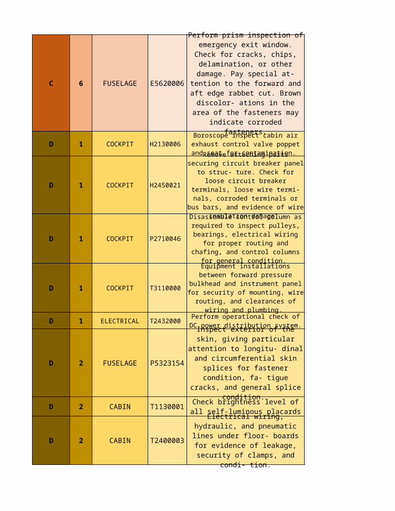
C 6 FUSELAGE E5620006
D 1 COCKPIT H2130006
D 1 COCKPIT H2450021
D 1 COCKPIT P2710046
D 1 COCKPIT T3110000
D 1 ELECTRICAL T2432000
D 2 FUSELAGE P5323154
D 2 CABIN T1130001
D 2 CABIN T2400003
Perform prism inspection of emergency exit window. Check
for cracks, chips, delamination, or other damage. Pay special at- tention to the forward and aft
edge rabbet cut. Brown discolor- ations in the area of the
fasteners may indicate corroded fasteners.
Boroscope inspect cabin air exhaust control valve poppet and seat for
contamination.
Remove attaching parts securing circuit breaker panel to struc- ture.
Check for loose circuit breaker terminals, loose wire termi- nals,
corroded terminals or bus bars, and evidence of wire insulation damage.
Disassemble control column as required to inspect pulleys, bearings, electrical wiring for proper routing
and chafing, and control columns for general condition.
Equipment installations between forward pressure bulkhead and instrument panel for security of
mounting, wire routing, and clearances of wiring and plumbing.
Perform operational check of DC power distribution system.
Inspect exterior of the skin, giving particular attention to
longitu- dinal and circumferential skin splices for fastener
condition, fa- tigue cracks, and general splice condition.
Check brightness level of all self-luminous placards
Electrical wiring, hydraulic, and pneumatic lines under floor-
boards for evidence of leakage, security of clamps, and condi-
tion.
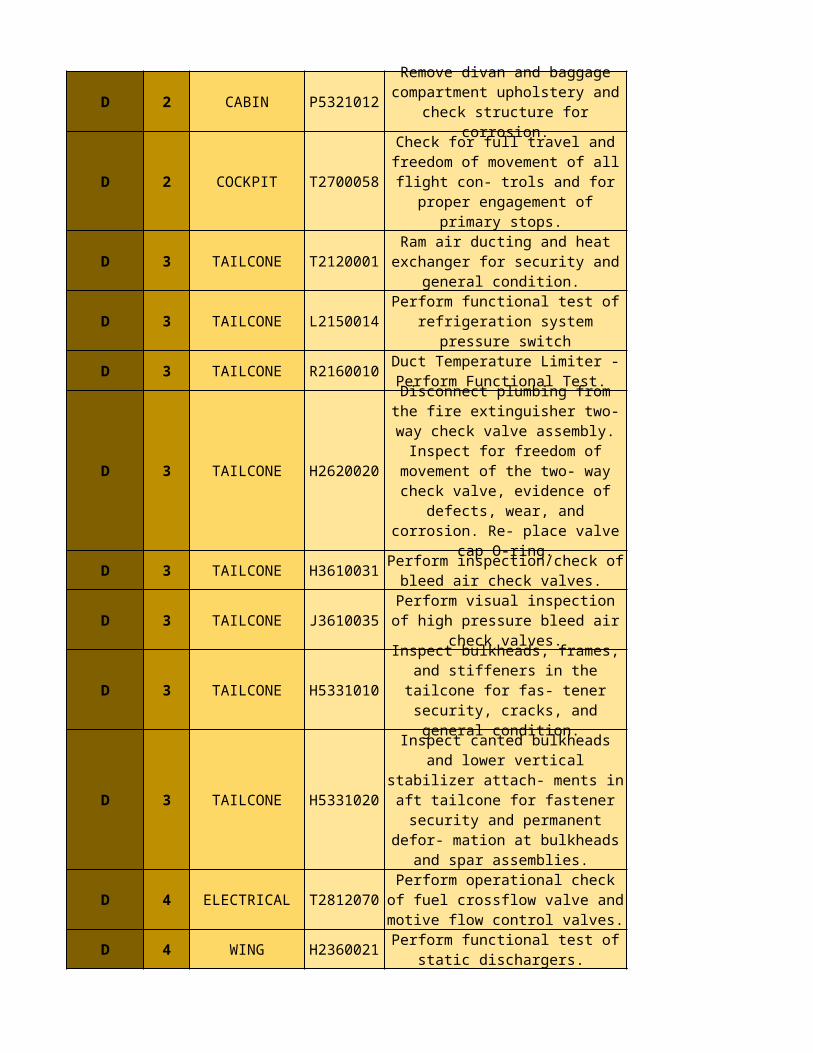
D 2 CABIN P5321012
D 2 COCKPIT T2700058
D 3 TAILCONE T2120001
D 3 TAILCONE L2150014
D 3 TAILCONE R2160010
D 3 TAILCONE H2620020
D 3 TAILCONE H3610031
D 3 TAILCONE J3610035
D 3 TAILCONE H5331010
D 3 TAILCONE H5331020
D 4 ELECTRICAL T2812070
D 4 WING H2360021
Remove divan and baggage compartment upholstery and check structure for corrosion.
Check for full travel and freedom of movement of all flight con-
trols and for proper engagement of primary stops.
Ram air ducting and heat exchanger for security and
general condition.
Perform functional test of refrigeration system pressure
switch
Duct Temperature Limiter - Perform Functional Test.
Disconnect plumbing from the fire extinguisher two-way check
valve assembly. Inspect for freedom of movement of the
two- way check valve, evidence of defects, wear, and corrosion.
Re- place valve cap O-ring.
Perform inspection/check of bleed air check valves.
Perform visual inspection of high pressure bleed air check valves.
Inspect bulkheads, frames, and stiffeners in the tailcone for fas-
tener security, cracks, and general condition.
Inspect canted bulkheads and lower vertical stabilizer attach-
ments in aft tailcone for fastener security and permanent defor- mation at bulkheads and spar
assemblies.
Perform operational check of fuel crossflow valve and motive flow
control valves.
Perform functional test of static dischargers.
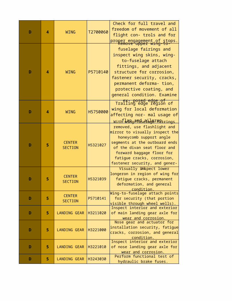
D 4 WING T2700060
D 4 WING P5710140
D 4 WING H5750000
D 5
D 5
D 5
D 5
D 5
D 5
D 5
Check for full travel and freedom of movement of all flight con-
trols and for proper engagement of stops.
Remove upper wing-to-fuselage fairings and inspect wing skins, wing-to-fuselage attach fittings,
and adjacent structure for corrosion, fastener security,
cracks, permanent deforma- tion, protective coating, and general condition. Examine ex- posed
edge of
Trailing edge region of wing for local deformation affecting nor- mal usage of flap and aileron.
CENTER SECTION
H5321027
With wing/fuselage fairings removed, use flashlight and mirror to visually inspect the
honeycomb support angle segments at the outboard
ends of the divan seat floor and forward baggage floor for
fatigue cracks, corrosion, fastener security, and gener-
al
CENTER SECTION
H5321039
Visually inspect lower longeron in region of wing for
fatigue cracks, permanent deformation, and general
condition.
CENTER SECTION
P5710141
Wing-to-fuselage attach points for security (that
portion visible through wheel wells).
LANDING GEAR
H3211020
Inspect interior and exterior of main landing gear axle for
wear and corrosion.
LANDING GEAR
H3221000
Nose gear and actuator for installation security, fatigue
cracks, corrosion, and general condition.
LANDING GEAR
H3221010
Inspect interior and exterior of nose landing gear axle for
wear and corrosion. LANDING
GEARH324303
0 Perform functional test of
hydraulic brake fuses.
D 5 NOSE
D 5 WING
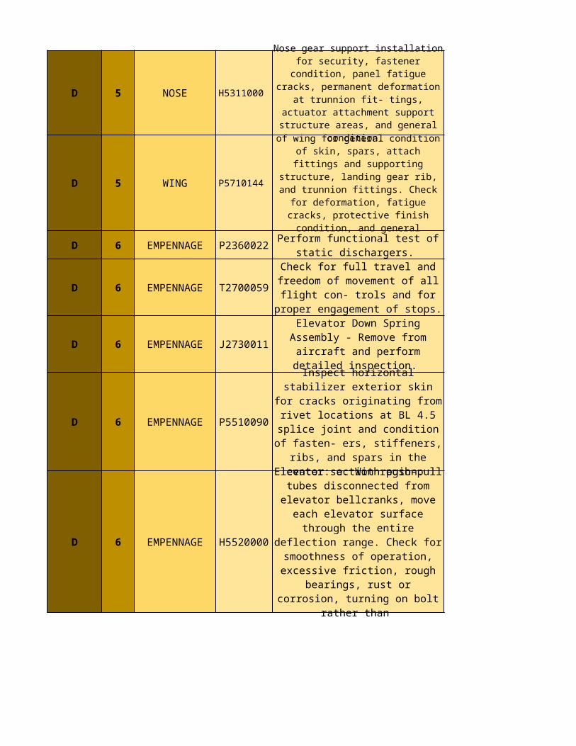
D 6 EMPENNAGE P2360022
D 6 EMPENNAGE T2700059
D 6 EMPENNAGE J2730011
D 6 EMPENNAGE P5510090
D 6 EMPENNAGE H5520000
H5311000
Nose gear support installation for security, fastener
condition, panel fatigue cracks, permanent
deformation at trunnion fit- tings, actuator attachment
support structure areas, and general condition.
P5710144
Wheel well and center section of wing for general
condition of skin, spars, attach fittings and supporting
structure, landing gear rib, and trunnion fittings. Check
for deformation, fatigue cracks, protective finish condition, and general
security. Perform functional test of static
dischargers.
Check for full travel and freedom of movement of all flight con-
trols and for proper engagement of stops.
Elevator Down Spring Assembly - Remove from aircraft and
perform detailed inspection.
Inspect horizontal stabilizer exterior skin for cracks
originating from rivet locations at BL 4.5 splice joint and condition
of fasten- ers, stiffeners, ribs, and spars in the center section
region.
Elevator: a. With push-pull tubes disconnected from elevator
bellcranks, move each elevator surface through the entire deflection range. Check for smoothness of operation, excessive friction, rough
bearings, rust or corrosion, turning on bolt rather than
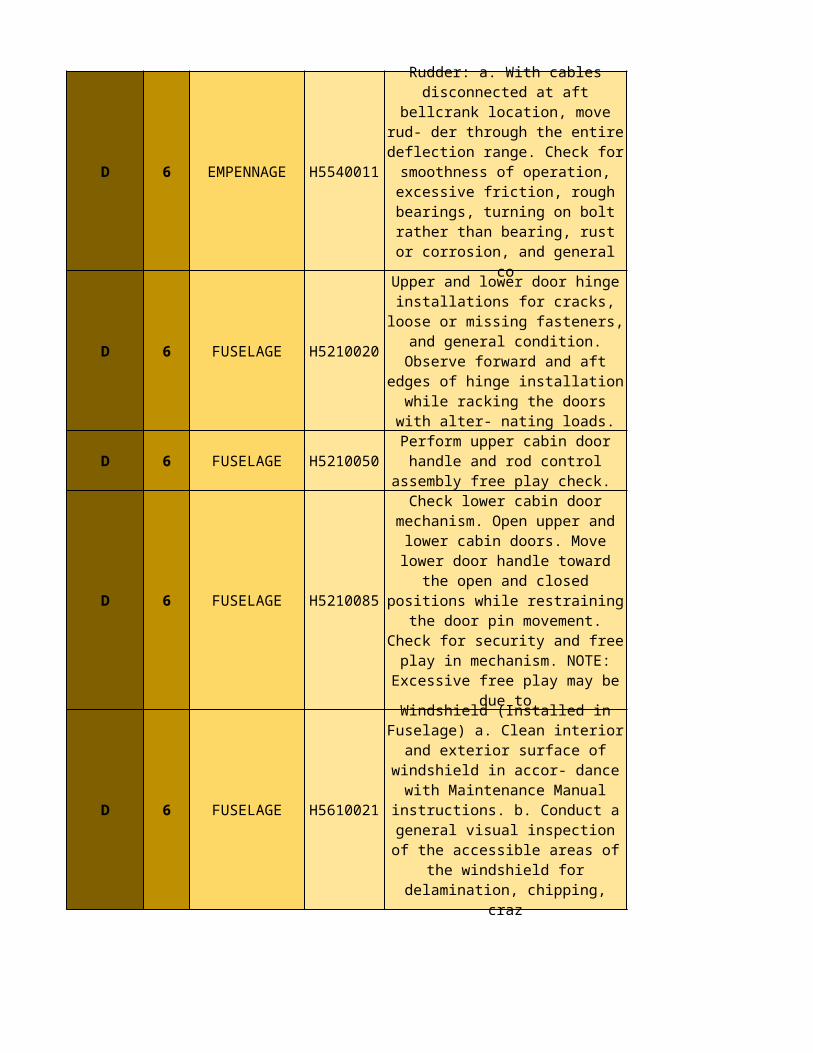
D 6 EMPENNAGE H5540011
D 6 FUSELAGE H5210020
D 6 FUSELAGE H5210050
D 6 FUSELAGE H5210085
D 6 FUSELAGE H5610021
Rudder: a. With cables disconnected at aft bellcrank
location, move rud- der through the entire deflection range.
Check for smoothness of operation, excessive friction,
rough bearings, turning on bolt rather than bearing, rust or corrosion, and general co
Upper and lower door hinge installations for cracks, loose or missing fasteners, and general
condition. Observe forward and aft edges of hinge installation while racking the doors with
alter- nating loads.
Perform upper cabin door handle and rod control assembly free
play check.
Check lower cabin door mechanism. Open upper and
lower cabin doors. Move lower door handle toward the open
and closed positions while restraining the door pin
movement. Check for security and free play in mechanism.
NOTE: Excessive free play may be due to
Windshield (Installed in Fuselage) a. Clean interior and exterior
surface of windshield in accor- dance with Maintenance Manual instructions. b. Conduct a general
visual inspection of the accessible areas of the
windshield for delamination, chipping, craz
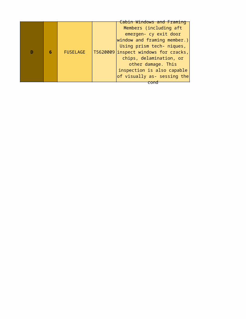
D 6 FUSELAGE T5620009
Cabin Windows and Framing Members (including aft emergen- cy exit door window and framing
member.) Using prism tech- niques, inspect windows for
cracks, chips, delamination, or other damage. This inspection is
also capable of visually as- sessing the cond


![[ATU] - Fases Do Capitalismo](https://img.pdfslide.us/doc/110x75/577c86b51a28abe054c25465/atu-fases-do-capitalismo.jpg)