Embed Size (px)
Citation preview
ME 492: Progress Report IDaimler Wind Tunnel Smoke Controller
(Daimler-TrucksNorthAmerica.com)
Sponsoring Company: Daimler Trucks North America
Contact Engineer: Matt MarkstallerProduct Validation(503) 745-68575160 N. Lagoon Ave.Portland, OR 97217
Team Members: Fadel Al JutailChris GrewellCraig LechtenbergMatt MeliusAndreas NylundMufeed Yacoub
Academic Advisor: Dr Raùl Bayoàn Cal

Table of ContentsIntroduction......................................................................................................................................3Mission Statement...........................................................................................................................4Project Plan......................................................................................................................................5PDS Summary.................................................................................................................................6External Search................................................................................................................................7Internal Search.................................................................................................................................8Top Level Final Design Evaluation...............................................................................................11Progress on Detailed Design..........................................................................................................12Conclusion.....................................................................................................................................15References......................................................................................................................................17Appendix A: Product Design Specifications.................................................................................18Appendix B: Component Analysis of the Wand Support Roller Box...........................................19Appendix C: Component Analysis of the Horizontal Carriage.....................................................21Appendix D: Component Analysis of the Smoke Wand...............................................................23
2 | P a g e
Introduction
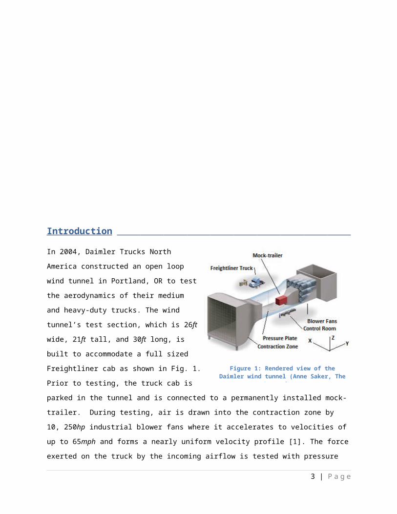
In 2004, Daimler Trucks North America constructed
an open loop wind tunnel in Portland, OR to test
the aerodynamics of their medium and heavy-duty
trucks. The wind tunnel’s test section, which is 26ft
wide, 21ft tall, and 30ft long, is built to
accommodate a full sized Freightliner cab as shown
in Fig. 1. Prior to testing, the truck cab is parked in
the tunnel and is connected to a permanently
installed mock-trailer. During testing, air is drawn
into the contraction zone by 10, 250hp industrial blower
fans where it accelerates to velocities of up to 65mph
and forms a nearly uniform velocity profile [1]. The force exerted on the truck by the incoming airflow is
tested with pressure sensors in the floor, which aid in determining the overall drag coefficient of the
truck.
In addition to measuring drag forces, Daimler uses smoke visualization techniques to analyze flow
characteristics such as boundary layer separation points. The smoke is generated and piped to a manual
smoke wand that discharges fluid tracking particles 2ft upwind of the desired region of the truck. Areas
with undesirable separation points are identified and adjustments to the truck’s external design are
made to lower the overall drag coefficient and ultimately improve the fuel economy of their medium
and heavy-duty trucks (Fig. 2).
Daimler has identified three major limitations
of their current smoke testing system for our
capstone team to improve. First, their smoke
wand is 15ft long which restricts the range of
the testable area, highlighted by Fig.3. The
second issue is the inability to consistently
repeat tests on areas of interest because of
the manual positioning of the smoke wand.
Lastly, the smoke wand deflects over 5in
3 | P a g e
Figure 1: Rendered view of the Daimler wind tunnel (Anne Saker, The Oregonian).
Figure 2: Smoke testing at the Daimler wind tunnel (Ross William Hamilton, The Oregonian)

under its own weight and oscillates under wind loading leading to unacceptable levels of inaccuracy.
Daimler has requested that our capstone team design an improved system that eliminates these
problems with their smoke testing system.
Figure 3: Illustration of Limited Smoke Wand Range with Daimler’s current smoke system.
Mission Statement
Currently, Daimler is using a manual smoke testing
system for their visual aerodynamic analysis and
they would like to implement an automated
system. The purpose of this project is to replace the
current method of manual smoke wand placement
with an electronically controlled system capable of
traversing the projected face of a typical
Freightliner medium and heavy-duty truck, 8.5ft by
14ft (Fig. 4). The system will also discharge smoke
at desired locations while maintaining a minimal
flow disturbance of the testing region. The goal of
the capstone team is to produce all fabrication, installation, and operation documentation to Daimler by
the end of the spring term which concludes on June 16th, 2012.
4 | P a g e
Figure 4: The projected area of the largest truck Daimler tests at their wind tunnel.

Project Plan
Table 1 illustrates tentative dates and major milestones of the Daimler Wind Tunnel Smoke Controller
project. The dates given are subject to change based on the needs of the customer, unforeseen
complications, or design changes. A more detailed project schedule can be seen in Table 2.
Table 1: Project plan milestones
Table 2: Gantt chart showing the project progress as of March 7th, 2012.
5 | P a g e

PDS Summary
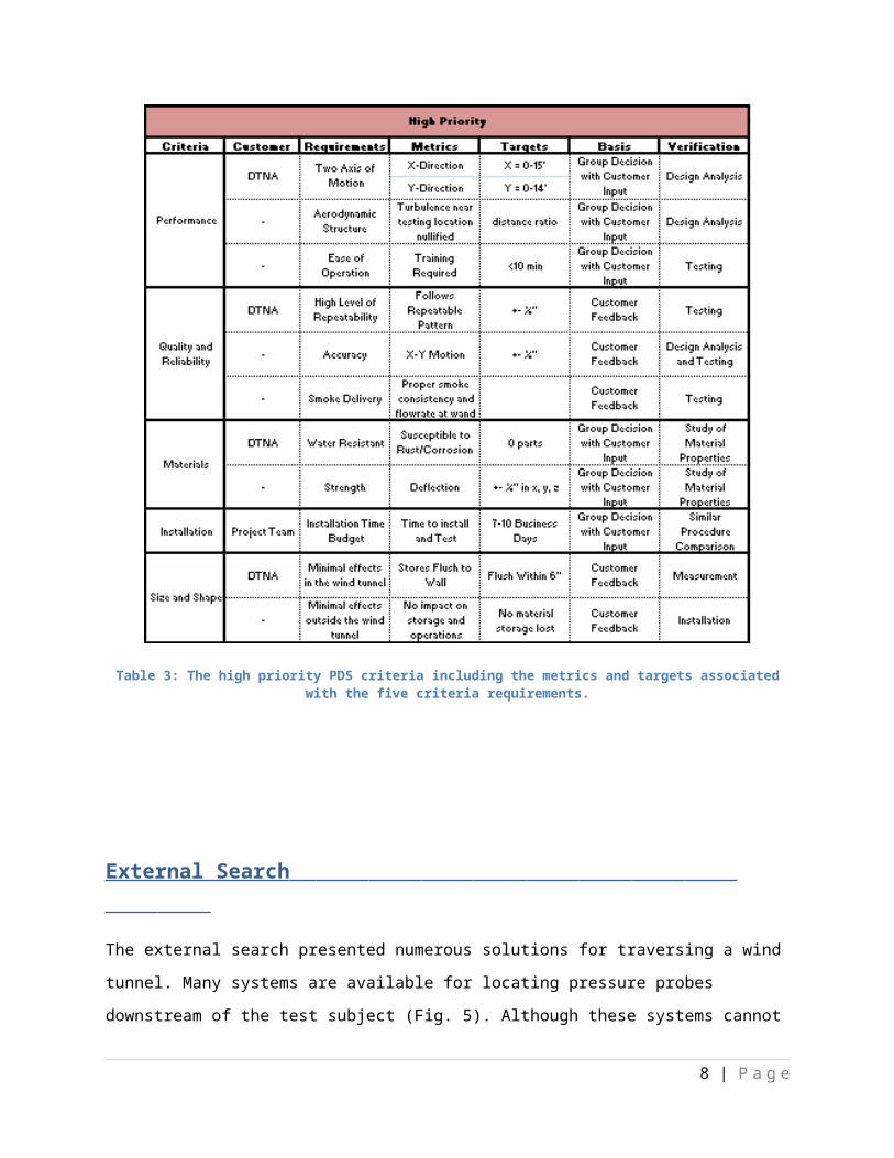
A PDS was created and completed January 30th. It established what the final product is intended to do by
fully defining its end user requirements (specifications). The specifications consist of the priority of
importance, metric, target, basis, and a means to verify the specification. Table 3 shows the high priority
product requirements. For the medium, low and not applicable requirements see Appendix A.
Table 3: The high priority PDS criteria including the metrics and targets associated with the five criteria requirements.
6 | P a g e

External Search
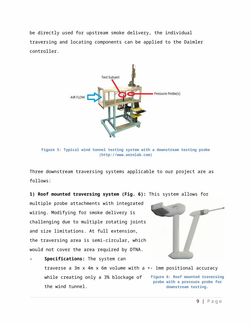
The external search presented numerous solutions for traversing a wind tunnel. Many systems are
available for locating pressure probes downstream of the test subject (Fig. 5). Although these systems
cannot be directly used for upstream smoke delivery, the individual traversing and locating components
can be applied to the Daimler controller.
Figure 5: Typical wind tunnel testing system with a downstream testing probe (http://www.aerolab.com)
Three downstream traversing systems applicable to our project are as follows:
1) Roof mounted traversing system (Fig. 6): This system allows
for multiple probe attachments with integrated wiring.
Modifying for smoke delivery is challenging due to multiple
rotating joints and size limitations. At full extension, the
traversing area is semi-circular, which would not cover the area
required by DTNA.
- Specifications: The system can traverse a 3m x 4m x
6m volume with a +- 1mm positional accuracy while
creating only a 3% blockage of the wind tunnel.
7 | P a g e
Figure 6: Roof mounted traversing probe with a pressure probe for downstream testing.
(http://www.quadratec-ltd.co.uk)
2) Roof mounted traversing system (Fig. 7): This system is used in
an automotive acoustic wind tunnel. The large structural
members are permanently affixed inside the wind tunnel to
obtain the stiffness requirements necessary for a critical 1st mode
frequency greater than 12Hz to prevent vibration during testing.
Direct application of this system would be extremely difficult due
to the support structure size.
- Specifications: The traversing system positions a range of
aerodynamic and acoustic probes (with a mass up to 25kg) to
an accuracy of 1.5mm in a working volume of 5m x 12m x
13m. Maximum traversing speed is 600mm/s and the entire
assembly, nearly 20 tons, is hung from the roof of the wind
tunnel.
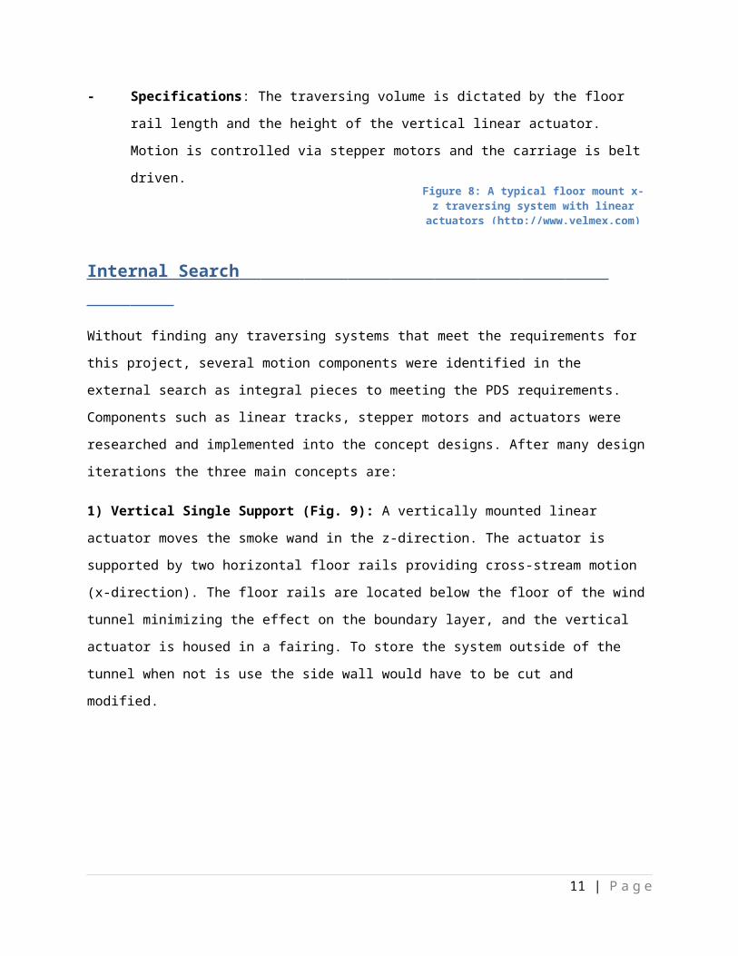
3) Floor mounted traversing system (Fig.8): Floor tracks
must be permanently installed inside the wind tunnel and
profile of the linear actuator would need modification to
reduce effects of obstruction/ air turbulence.
- Specifications: The traversing volume is dictated by
the floor rail length and the height of the vertical
linear actuator. Motion is controlled via stepper
motors and the carriage is belt driven.
Internal Search
Without finding any traversing systems that meet the requirements for this project, several motion
components were identified in the external search as integral pieces to meeting the PDS requirements.
Components such as linear tracks, stepper motors and actuators were researched and implemented into
the concept designs. After many design iterations the three main concepts are:
8 | P a g e
Figure 7: Downstream probe used in an automotive acoustic wind tunnel
(http://www.quadratec-ltd.co.uk)
Figure 8: A typical floor mount x-z traversing system with linear actuators (http://www.velmex.com)
1) Vertical Single Support (Fig. 9): A vertically mounted linear actuator moves the smoke wand in the z-
direction. The actuator is supported by two horizontal floor rails providing cross-stream motion (x-
direction). The floor rails are located below the floor of the wind tunnel minimizing the effect on the
boundary layer, and the vertical actuator is housed in a fairing. To store the system outside of the tunnel
when not is use the side wall would have to be cut and modified.
Figure 9: The Vertical Single Support concept design.
2) Cantilever (Fig. 10): A carbon fiber smoke wand is driven by a horizontally mounted linear actuator
and extends from the side of the test section. Vertical rails allow for vertical motion while the extension
and retraction of the wand provides horizontal motion. To limit the negative effects of
vibration/oscillation, the smoke wand support needs to be rigid. Only one side of the tunnel would have
to be modified and the main structure of this system would remain outside the wind tunnel, minimizing
blockage effects and turbulence.
Figure 10: The Cantilever concept design.
9 | P a g e

2) Vertical Dual Support (Fig.11): Similar to the previous design, a vertical linear actuator moves the
smoke wand in the z-direction and rides on a horizontal rail in the floor. An extra ceiling mounted rail is
used to support both ends of the actuator to provide extra rigidity to the system, requiring additional
structural members above the wind tunnel ceiling. For full retraction of the smoke system, the ceiling
and sidewall of the tunnel would have to be cut and modified.
Figure 11: The Vertical Dual Support concept design.
10 | P a g e
Top Level Final Design Evaluation
The three concept selections created from the internal search were evaluated in a Concept Scoring
Matrix (Table 4) based upon their performance characteristics from the PDS (Table 1). The criteria for
each concept was from 1 to 5, 1 being the lowest, and multiplied by a weight factor.
Table 4: Concept Scoring Matrix with the high priority PDS category criteria scored and weighted.
Performance: Although the traversing method is slightly different for the three designs, all of them are
able to traverse the 340ft2 cross section required by Daimler. However, each of them accomplishes this
with a slightly different aerodynamic impact. The vertical single support requires the largest cross-
stream profile to support the vertical linear actuator, the vertical dual support has a smaller cross-
stream profile, however the cantilever out ranks them all with its relatively thin airfoil smoke wand
support. Another advantage of the cantilever design is that the horizontal orientation disrupts the air
stream at a single point in the plane of interest (x-z) unlike the vertical designs that disrupt the steam
continuously in the z-direction. Operating each of the three designs will require the same control
system.
Quality and Reliability: The ability to repeat movements and locations consistently is the same for the
three designs as each design uses the same type of linear actuators. However, the wand tip accuracy of
the cantilever design suffers more than the other designs because of the deflection of the unsupported
wand due to gravity and wind loading when it is in operation. Also, the vertical and horizontal inaccuracy
11 | P a g e

will vary depending upon the length of the wand extended into the wind tunnel making a precise
prediction of the tip accuracy more difficult. The smoke delivery to the cantilever system is not as
difficult to implement into the design when compared to the vertical designs that require a smoke hose
reel system to lengthen and retract the hose during operation.
Materials: The cantilever design is more resilient to Daimler’s rain testing because the majority of the
wear components are located outside of the tunnel. The vertical designs require an x-direction rail to be
mounted on or below the wind tunnel floor and subjected to the rain testing. The cantilever design
eliminates the need to use water resistant components, but it requires materials that can properly
support the smoke wand 20ft into the tunnel. Because of this the components will experience more
stress and the smoke wand itself will fatigue over time and will eventually need to be replaced. Similarly,
the vertical single support design will fatigue faster when compared to the vertical dual support from
the cyclical wind loading on the vertical rail, requiring more robust materials and components.
Installation: Maintaining the operation of the wind tunnel during installation is a primary concern for
Daimler as they cannot afford long or short periods of downtime. The cantilever requires a 4-8 in slot in
the wind tunnel wall to allow the wand to protrude into the tunnel during testing. In comparison, the
vertical designs require cutting into the tunnel floor to mount a linear actuator, supplying a drainage
system to accommodate rain testing, and modifying the tunnel wall and or roof to store the structure
when not in use. Thus, the cantilever design received the highest score for the installation criteria.
Size and Shape: During drag testing the smoke system is not used and has to be stored flush to the wind
tunnel wall. In its stored location, it is crucial the system does not affect the drag testing results as any
alteration to the floor, walls, or ceiling will change the boundary layer characteristics in the wind tunnel.
The vertical dual support was rated the lowest for this criteria. The vertical single support is slightly
better as the ceiling does not need to be altered, but the cantilever system is the optimal design because
of its low impact when not in use.
Progress on Detailed Design
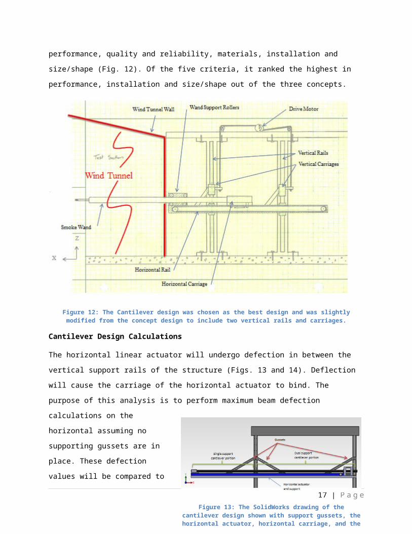
Among the three concept designs, the cantilever was selected with the guidance of Daimler based upon
the five high priority PDS categories: performance, quality and reliability, materials, installation and
size/shape (Fig. 12). Of the five criteria, it ranked the highest in performance, installation and size/shape
out of the three concepts.
12 | P a g e
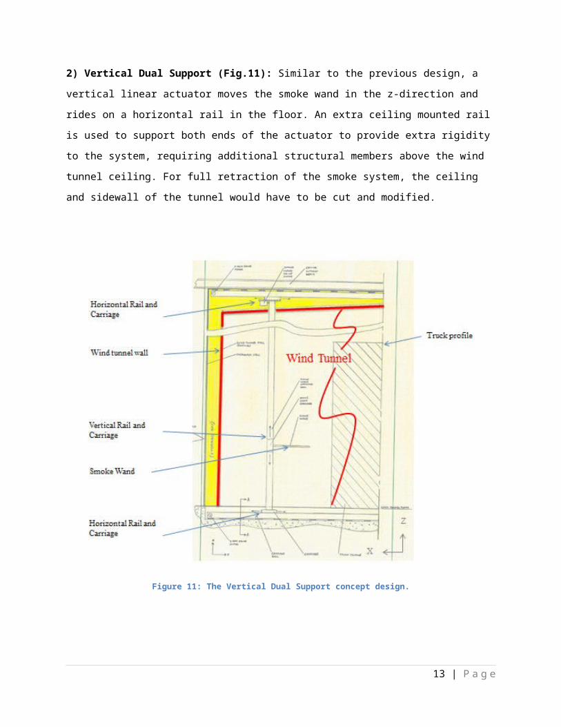
Figure 12: The Cantilever design was chosen as the best design and was slightly modified from the concept design to include two vertical rails and carriages.
Cantilever Design Calculations
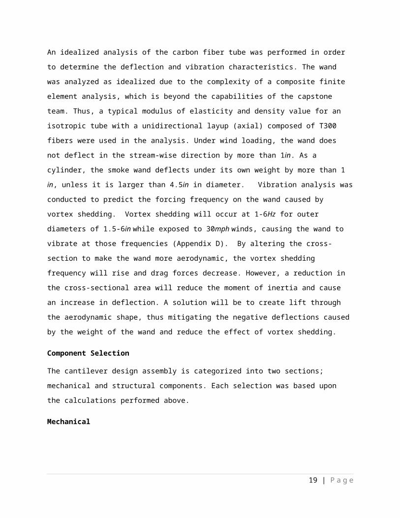
The horizontal linear actuator will undergo defection in between the vertical support rails of the
structure (Figs. 13 and 14). Deflection will cause the carriage of the horizontal actuator to bind. The
purpose of this analysis is to perform maximum beam defection calculations on the horizontal assuming
no supporting gussets are in place. These defection values will be compared to the maximum acceptable
defections specified by the linear actuator manufacturer (to be determined) to validate this portion of
the design. The resulting maximum
defections were 0.0146in and 0.0046in
for the dual support cantilever and single
supported cantilever, respectively
(Appendix C). These values will be used
with the manufacturer’s max defection
specifications in deciding proper linear
actuator for application.
13 | P a g e
Figure 13: The SolidWorks drawing of the cantilever design shown with support gussets, the horizontal actuator, horizontal carriage, and the
carbon fiber
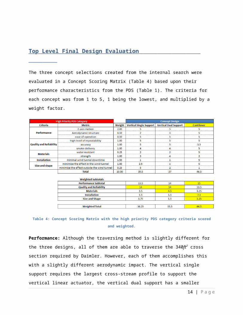
Figure 14: Detail of the distributed loads acting on the horizontal actuator
Figure 15 illustrates the initial concept of the tube support carriage shown with the reaction loading on
the tube support carriage rollers. This information will be used to size the rollers and support structure.
The analysis was performed at the maximum predictable loading. The resultant maximum radial load for
any one of the support rollers is 796.2lb f at 45 ° (Appendix B). The rollers will need to be sized
accordingly.
Figure 15: The reaction forces on the support rollers
An idealized analysis of the carbon fiber tube was performed in order to determine the deflection and
vibration characteristics. The wand was analyzed as idealized due to the complexity of a composite finite
element analysis, which is beyond the capabilities of the capstone team. Thus, a typical modulus of
elasticity and density value for an isotropic tube with a unidirectional layup (axial) composed of T300
fibers were used in the analysis. Under wind loading, the wand does not deflect in the stream-wise
direction by more than 1in. As a cylinder, the smoke wand deflects under its own weight by more than 1
in, unless it is larger than 4.5in in diameter. Vibration analysis was conducted to predict the forcing
frequency on the wand caused by vortex shedding. Vortex shedding will occur at 1-6Hz for outer
diameters of 1.5-6in while exposed to 30mph winds, causing the wand to vibrate at those frequencies
(Appendix D). By altering the cross-section to make the wand more aerodynamic, the vortex shedding
frequency will rise and drag forces decrease. However, a reduction in the cross-sectional area will
reduce the moment of inertia and cause an increase in deflection. A solution will be to create lift
14 | P a g e
through the aerodynamic shape, thus mitigating the negative deflections caused by the weight of the
wand and reduce the effect of vortex shedding.
Component Selection
The cantilever design assembly is categorized into two sections; mechanical and structural components.
Each selection was based upon the calculations performed above.
Mechanical
Horizontal Actuator System: PBC Linear: MT Series MTB80 Belt Driven Linear Actuator without
stepper motor. 3.15in x 3.15in x 236.22in
Vertical Actuator System: Thompson: 2DA Dual rail shaft with integrated carriage
Lifting motor: possibly a stepper motor winch, DC or AC motor
Structural
Vertical Supports: W10x22 Steel I-beam with 1
in thick baseplate, vertical rail mounts, and
horizontal I-beam mounting plate
Horizontal Actuator Support: 4in x 4in x 0.25in
x 8ft long steel box tubing with horizontal
actuator and Roller Support Box mounts and
struts
Roller Support Box: see Fig. 16 (TBD)
Smoke wand: Forte Carbon Fiber Products sail
mast tube 18ft long
Conclusion
At this point the PDS, internal and external search, concept brainstorming and concept selection have
been completed. The concept selected by Daimler is the cantilevered smoke delivery system. They
selected this system because it provided most of their design requirements, while having the least
installation impact on the tunnel. The team is now in the detailed design portion of the project. Major
components such as the horizontal actuator, vertical linear support rail, and “I” beam support structure
have been selected. A SolidWorks model of the cantilever system has been created using the
15 | P a g e
Figure 16: SolidWorks drawing of the roller box.

aforementioned parts (Fig. 16). Effort is now being focused on designing the roller box and selecting the
profile for the carbon fiber tube.
Daimler has expressed concerns about the pace of the project and has requested that the team dedicate
the remainder of the capstone experience into more design revisions. Ultimately, the capstone team will
deliver detailed design plans and specifications with minimal fabrication. Due to this and the concept
chosen by Daimler, changes to the PDS and missions statement are required. The “accuracy ±0.5in”
specification is to be omitted from the PDS due to unknowns associated with the behavior of a
cantilevered carbon fiber tube under wind loading. The complex properties of composites make a finite
element analysis of the purposed smoke wand unreliable with our level of knowledge. Thus, the
accuracy of smoke delivery will not be verifiable until the system is installed. Also, the team’s mission
statement will no longer include fabrication and installation of the system.
Going forward, the capstone team will focus its efforts in two directions, furthering the detailed design
portion of the complete system, and designing fabricating and testing one part of the system. The
complete system will be designed conceptually and tested analytically. The team and Daimler have
tentatively agreed on the roller block as the part to be fabricated. A proposal will be submitted to
Daimler, detailing the team’s intention in regards to the completion of the roller block. Upon their
approval, the roller block will be fabricated and tested to verify the design. The team feels it is on track
to complete the project on time.
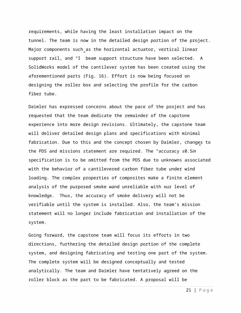
Figure 17: SolidWorks drawing of the cantilever design with the horizontal linear actuator, vertical rails, carbon fiber smoke wand, roller box, horizontal actuator support gussets and the support structure shown with the wind tunnel.
16 | P a g e
References
1. Saker, Anne. "Swan Island Wind Tunnel Puts Big Rigs to the Test." Oregon Local News, Breaking News, Sports & Weather. The Oregonian, 28 Dec. 2008/. Web. 18 Feb. 2012. <http://www.oregonlive.com/news/index.ssf/2008/12/wind_tunnel.html>.
2. "Daimler Trucks North America North America's Leading Manufacturer of Commercial Trucks." Daimler Trucks North America LLC North America's Leading Manufacturer of Commercial Trucks. Web. 20 Jan. 2012. <http://www.daimler-trucksnorthamerica.com/news/mediaroom/resources/image-gallery-facilities.aspx>.
17 | P a g e

Appendix A : Product Design Specifications
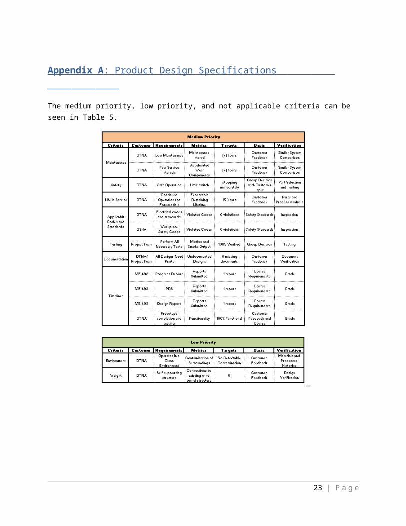
The medium priority, low priority, and not applicable criteria can be seen in Table 5.
Table 5: The medium priority, low priority, and not applicable PDS criteria
18 | P a g e
Appendix B : Component Analysis of the Wand Support Roller Box
Analyst: Chris GrewellDate: 2-26-2012
Summary: To determine the reaction loading on the tube support carriage rollers. This information will be used to size the rollers and support structure. Figure 16 illustrate the initial concept of the tube support carriage.
Figure 16: SolidWorks drawing of the roller box.
Evaluation: The analysis was performed at the maximum predictable loading as seen in Fig. 15. The resultant maximum radial load for any one of the support rollers is 796.2lb f@45 °. The rollers will need to be sized accordingly.
19 | P a g e

Figure 15: The reaction forces on the support rollers
Analysis:
Given: Tube weight of 30lbf and end load of 5 lbf.; wind loading in z direction of a maximum 80 lbf distributed over last 16’ of tube; tube support rollers are 1’ apart
Find: Vertical (y) reaction forces, Horizontal (z) reaction forces at support rollers.
Assumptions: Wind loading is totally horizontal and the distributed loads of the tube weight and wind force can be approximated as lumped masses at the centroids.
Solution:
Gravitational loading
∑M ay=Fby−17 '∗5 lb f−8.5'∗30lb f=0 , Fby=340lb f ↑
Fay=340lb f−30 lbf−5 lbf=305 lbf ↓
Wind loading
∑M az=Fbz−9 '∗80 lbf=0 ,Fbz=720 lbf ↑
Faz=720 lbf−80lb f=640 lbf ↓
Maximum resultant force
resultant=√720lbf2+340lbf
2=796.2lbf @45 °
20 | P a g e
References: N/A
Appendix C : Component Analysis of the Horizontal Carriage
Analyst: Chris GrewellDate: 2-28-2012
Summary: The horizontal linear actuator will undergo defection in between the vertical support rails of the structure (Fig. 13). If this deflection is too large, it can cause the carriage of the horizontal actuator to bind. The purpose of this analysis is to perform maximum beam defection calculations on the horizontal assuming no supporting gussets are in place. These defection values will be compared to the maximum acceptable defections specified by the linear actuator manufacturer (to be determined) to validate this portion of the design.
Figure 13: The SolidWorks drawing of the cantilever design shown with support gussets, the horizontal actuator, horizontal carriage, and the carbon fiber
21 | P a g e
Single support cantilever portion
Dual support cantilever portion
Gussets
Horizontal actuator and support
Evaluation: The resulting maximum defections were 0.372mm and 0.118mm for the dual support cantilever and single supported cantilever respectively from the loading seen in Fig. 14. These values will be used with manufacturers max defection specifications in deciding proper linear actuator for application.
Figure 14: Detail of the distributed loads acting on the horizontal actuator
Analysis:
Given: Dual cantilever supported length = 3.66m (12ft), distributed load = 383.3NSingle cantilever support beam length = 1.52m (5ft), distributed load = 159.2NMoment of inertia (I) = 1.03732e-5 m4 (see Fig. 18)Elastic modulus (E) = 7GPa
Figure 18: SolidWorks drawing of the extruded aluminum horizontal carriage showing the moment of inertia, I
Find: Max defection of dual supported cantilever and single supported cantilever beam.
Assumptions: No gusseting (worst case scenario), the connections to the vertical rails act as a true cantilever and loading is evenly distributed.
Solution:
22 | P a g e
3.66m1.52m
383.3 N159.2 N
Max defection of dual cantilever support = 5348
Wl3
8EI (1)
5348
383.3 N∗3.66m3
70e9Pa∗1.03732e-5m4 =0.000372m∨0.372mm=0.0146in
Max defection of single cantilever support = Wl3
8 EI (2)
159.2N∗1.52m3
8∗70e9 Pa∗1.03732e-5m4 =0.000118m∨0.12mm=0.0046in
References:
Equations 1&2, retrieved on 2-28-2013 from http://www.engineersedge.com/beam_bending/calculators_protected/beam_deflection_1.htm
Appendix D : Component Analysis of the Smoke Wand
Analyst: Matt MeliusDate: 2-29-2012
Summary: Under wind loading the wand will not deflect in the stream-wise direction by more than 1”. Carbon fiber is light-weight and very strong which makes it ideal for the traverse system
As a cylinder, the smoke wand will deflect under its own weight by more than 1” unless it is larger than 4.5” in diameter. Vortex shedding will occur at very low frequency, which will cause the wand to vibrate under wind loading.
By altering cross-section to make the wand more aerodynamic vortex shedding frequency should rise and drag force should decrease. This will likely cost strength in direction of largest deflect. Solution will be to create lift through the aerodynamic shape.
Evaluation: Beam will deflect under its own weight by more than 1” unless it is larger than 4.5” in OD. Vortex Shedding will occur at 1-6 hz under 30 MPH wind Deflection in Y-direction is of greatest effect at low wind speeds. (30mph
Analysis:
Given: 3” OD, L = 17’, Cantilever Cylinder, Orientation = cross flow
23 | P a g e

Find: Re , Drag Coefficient (Cd), Drag Force = F, Vortex Shedding Frequency = f , Moment of Inertia = I, Deflection = y , Mass = m
Assumptions: Smooth Surface, Steady Flow, Incompressible Fluid, Distributed Load Strouhal number =0.19 (10^4<Re<10^6)
Solution:
Reynold’s Number : Re=VD
νDrag Coefficient:
Cd = 1.18+6.8/(Re^(0.89))+1.96/(Re^(0.5))-0.0004*Re/(1+3.64*EXP(7*B6^2))
Drag Force : Df =
12ρV 2 (L∗d o )
Vortex Shedding Frequency: f (hz )=St∗VD
Moment of Inertia: I= P
64(Do4−Di4 )
Deflection of a Cantilever Cylinder: y= fl3
EI∗8
Cross-sectional area: Ac=
P4
(Do2 )−
P4
(Di2)
Mass: M=ρA c L
Table 6: The material properties of the isotropic tube with a unidirectional layup (axial) composed of T300 fibers used for the smoke wand analysis and the wind speeds associated with smoke testing
Table 7: Fluid force calculations on the carbon fiber tube at 30 MPH
24 | P a g e
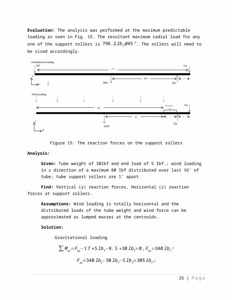
Table 7: Fluid force calculations on the carbon fiber tube at 60 MPH
Table 7: Wind load deflections of the carbon fiber tube at different OD’s and ID’s
Table 8: Gravitational deflections of the carbon fiber tube at different OD’s and ID’s
References: White, Frank M. Viscous Fluid flow. McGraw-Hill Science/Engineering.Math; 2nd Edition. January 1, 1991.
25 | P a g e