Embed Size (px)
Citation preview

FarmTRXYieldMonitor–InstallGuide.Beforeinstalling,makesuretoreadtheQuickStartGuide:www.FarmTRX.com/documentationThisguidewillwalkthroughtheinstallationofaFarmTRXYieldMonitor.ItisshownbeinginstalledonaNewHollandCR9060,butshouldbetypicalofallNewHollandCRseries&CaseAFXcombines,andissimilartotheinstallprocessformostothercombines.
SystemOverview:
OverviewofInstallationLocations
1. FarmTRXYieldMonitor:The“brains”oftheoperation.Thisdevicefeaturesanon-board
computerthatconnectstotheopticalyieldsensors,16gbofon-boardstorage(enoughtostoreyearsofharvestingdata),aGPSantenna,andBluetoothconnectivityforpairingwithasmartphoneortablet.Itmountsinthecabandneedstobewiredintoswitched12Vpower.1.1GPSAntenna(optional):ThisisrequiredwhenitisnotpossibletomounttheYieldMonitoralongthecenter-lineofthecab,oriftheharvestercabhasametalroof.
2. Mass-FlowOpticalSensors:Twosensorswillbeinstalledoneithersideofthecleangrainelevator.Alightbeamissentbetweenthetwosensors,allowingforthemeasurementofthevolumeofgrainoneachpaddle.ThesesensorswillbewireddirectlytotheYieldMonitorthroughthesuppliedharnesses.
ComponentsLayout

ComponentsOverview:
1. FarmTRXYieldMonitor2. OpticalYieldSensors3. OpticalSensorMountingBrackets4. 8ft.InterconnectCable5. 20ftPrimaryCable
Otherincludedhardware:• 8x5/32PopRivets• 2xT-Tap(18-14AWG),Blue• 2xT-Tap(22-18AWG),Red• 6”Zipties
• 24”XLZipTies• 2xPlasticSpacers• 4xM18Nuts• 4xM18Washers
ToolsRequired:• PowerDrill • MeasuringTape• 5/32”DrillBit • FramingSquare• ¾”StepDrillBit • Marker,Pen,orPencil• ¾”StepDrillBit • Screwdriver• Pliers,ViceGrips,SideCutters • MaskingTape• CenterPunch • RoundBastardFile• RightAngleDrill(forcombineswithtightclearancebehindcleangrain
elevator)

1.InstallYieldMonitorComponentsusedinthisstep:
YieldMonitor 20ft.PrimaryCable
TheYieldMonitorinstallsinthecabofyourcombine.Itneedstobepoweredby12Vswitchedpower.SinceitcontainsaGPSantenna,itshouldbemountedasclosetothecenterlineofyourcombineaspossible(alternatively,theYieldMonitorcabbemountedelsewhereandanexternalGPSantennacanbeconnectedandmountedalongthecenterline)InstallYieldMonitor:
1. Removeanyheadlinerpanelsorlightsneededtoaccess12Vswitchedpowerandaspacetoinstalltheyieldmonitor.
2. Locate12Vswitchedpowerlinestotapinto.3. UsethesuppliedT-SpliceConnectorstoconnectto+12V&Ground.Useplierstosnap
theT-SpliceConnectorsontothewires.Besuretousethecorrectsizeconnector,andensuretheconnector“snaps”shut.
UsetheBlueT-Spliceconnectorfor18-14AWGwireUsetheBlueT-Spliceconnectorfor22-18AWGwire.
4. WiththeT-Spliceconnectorsattachedto12Vswitchedpower,attachtheRed&BlackspadeconnectorsfromtheleadsonthePrimaryCableto+12V&Ground,respectively.
5. Connectthe15PinconnectorofthePrimaryCabletotheYieldMonitor&tightenscrews.
a. Totestthepower:turnonthecombine,thenuseyoursmartphonetosearch/scanforBluetoothdevices.Adevicecalled“YM:___”shouldappear.
6. InstallYMoncenter-lineofcombine.Removeanypanelsorlightsnecessarytoaccessaspotalongthecenterline.MounttheYieldMonitorwiththelabelfacingskywaysandusedoublesidedtapetomountitinplace.ApotentialplacetomountthetheYieldMonitorfortheinstallationpicturedherewouldbeinfrontofthecablightonthecenter-line.
a. Ifpoweraccessandcableroutingistoodifficult,oryourcombinehasametalroof,thenseebelow
7. UsinganexternalGPS:screwinganexternalGPSontothethreadedSMAconnectorontheYieldMonitorwillturnofftheinternalGPS,andinsteadusetheattachedantenna.ThisallowsyoutomounttheYieldMonitoranywhereinthecaborontheroof.

Showingpossibleinstalllocationofyieldmonitorinmiddleofheadliner
a. Alternative:InstalltheYManywhereinsidecabandalignGPSantennaalong
centerlineofcombine(shownbelow).
ShowingYieldMonitorinstalledinaftrighthandcornerofcab(whereswitchedpoweris
convenientlyaccessible)
InthisinstalltheGPSantennawasinstalledforwardofthecablightintheheadliner.ThisplacestheGPSantennaalongthecenter-lineoftheharvester.CableRouting:
8. OncetheYieldMonitorismounted,routethePrimaryCablethroughyourcab/headlinerandouttounderneathyourcab.Youwillneedtorouteittowardsthecleangrainelevator.
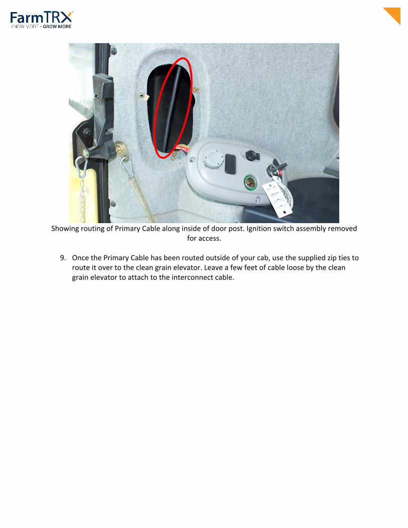
ShowingroutingofPrimaryCablealonginsideofdoorpost.Ignitionswitchassemblyremoved
foraccess.
9. OncethePrimaryCablehasbeenroutedoutsideofyourcab,usethesuppliedziptiestorouteitovertothecleangrainelevator.Leaveafewfeetofcableloosebythecleangrainelevatortoattachtotheinterconnectcable.

2.InstallOpticalSensorsComponentsusedinthisstep:
OpticalSensors MountingBrackets
Sensorinterconnectcable
Inthisstepyouwillbemountingtheopticalyieldsensorsonyourcleangrainelevator.Thelocationofthemountingpointisfoundinatablebelow.PreparingSensors&Brackets:
1. Mountopticalsensorsinmountingbrackets.Usesuppliednuts,washers,andplasticspacers.
MountingOrder:Nut,washer,bracket,washer,nut,spacer.
Lightlyhandtightenjamnutstomakefaceofsensorflushwiththemountingfaceofthebracket(shownabove)

2. Screwtheplasticspacerontothesensoruntilitisflushwiththefaceofthesensor,thenscrewthespacerslightlymoretorevealonlyonethreadofthesensor.Thiswillhelpthesensorsitatthecorrectdepthinthecleangrainelevator.
3. OnesensorhasasetofLEDlightsrecessedinthebarrel.Thesewillhelpyoutestthesystem,soensuretheyarepointedawayfromthehingeofthebracket.(shownabove)

MountingSensors&Brackets:Next,youwillneedtomeasureandmarkwheretomeasure,mark,anddrillholesforthesensorsonthecleangrainelevator.Theymountintheinside&outsidefaceoftheelevator,towardsthebackofthecombine(wherefilledpaddlesofgrainpassby).Thetablebelowshowsthemeasurementsforcommoncombines:Combine Model DistanceX(in) HeightY(in)CaseIH 1660 1.75 41.5 1680 1.75 75.5 2X88 1.75 75.5 7088 1.75 75.5 7120,8120 1.5 57NewHolland CR9XX,CR9XXX 1.75 62 TR9X 1.5 43 TX JohnDeere 9500 2.25 62 96X0 2.25 62 9X50 2.25 33 9X60 2.25 33 9X70 2.25 33Gleaner R7X 1.25 56Challenger 670 1.5 70 670B 1.75 65Cat UseExisting
SensorHoles
Ifyourmodelisnotshownhere,ensuretheopticalsensorslieinthemiddleofthecleangrainelevatorpaddles.
Distance(X)fromthebackofthecleangrain
elevatortothecenterofthedrillholeHeight(Y)fromthecenterofthebearing
tothecenterofthedrillhole
X
DiagramofOpticalSensorPlacement
&Operation

1. Usingmeasurementsfromthetableabove,measure&marktheheight(Y).Measure
fromthecenterofthebearing,toheight(Y),andmark.Werecommendusingmaskingtapetomakemarkingtheheighteasier.Useaframingsquaretotracetheheight(y)acrossthemaskingtapeonthecleangrainelevator.Itisveryimportanttoinstalltheopticalsensorsdirectlyoppositeeachother,sotakecarewithmarkingthemountingholes.
Shown:linedrawnontapetomarkexactheightofsensorsfrombottombearing.
2. Withtheheight(Y)markedacrossthecleangrainelevator,measure&markthe
distance(X).
Shown:markedsensorholelocation(x)fromofthebackofthecleangrainelevator.
3. Withheight(Y)anddistance(X)marked,useacenterpunchtomarkthelocationfor
drillingthesensormountingpilotholes.

4. Atthemarkedlocation–drillapilotholeusinga5/32”drillbit.
5. Usingthepilotholeasastartingpoint-useastepdrilltodrilla¾”hole.

Usingthestep-drill-bittodrill¾”hole
Showing:step-drillbitused.
6. Useafiletoremovesharpbursfromthedrilledhole.
7. Mountthesensorbrackets:Slideheadofsensorintothenew¾”hole.Loosenjamnutsonsensorandslidethebracketuntilthe4-holepatternislocatedinthemiddleofthecleangrainelevator.Presstheheadofthesensorintothe¾”hole,holdthebracketat90degreestotheverticaledgeoftheelevator,andmarkthe4-holepatternofthebracketfordrilling.

8. Oncebracket&sensorarealigned,drilloneholewitha5/32”bit.
9. Choosecorrectsensortoinstall:Beforepop-rivetingthesensoron,makesuretoselectthesensorwiththeLEDlightinthebarrel.HavingthisLEDlightvisiblewillhelptotestthesystem.(Shownbelow)
10. Next,installonepoprivettoholdthebracket,thendrilltheremainingholes.

Useapoprivetstomountthebrackettothe1stdrilledhole.
11. With1poprivetinstalled,drilltheremaining3holesandinstalltheirpoprivets.
12. Repeattheprocessontheinsidefaceofthecleangrainelevator.Takecaretoensurethe¾”holeisdrilleddirectlyacrossfromtheother(usingthesamex,ymeasurements).
Repeattheprocessontheinsidefaceofthecleangrainelevator.Takecaretoensurethe¾”
holeisdrilleddirectlyacrossfromtheother(usingthesamex,ymeasurements).
Ifaccesstothebackofthecleangrainelevatorisrestricted,youcancreateasheetmetaldrillingtemplateforthesensorpilothole(fortheharvester’sspecificXdimension)anduseanangleddrilltodrillthepilotandsensorholes.

13. Oncebothbracketsandsensorsaremounted,usetheincludedXLziptietoholdthe
bracketstogetherasshown:
14. Withthebracketsandsensorsmounted,attachtheconnectorsofthesensorcablestotheconnectorsontheInterconnectCable.
15. ConnecttheInterconnectCabletothePrimaryCable.Ziptieexcesscableinabundleawayfrommovingparts.
Cablesconnected&ziptiedoutoftheway.
NOTE:Therewillbeanopenconnectorontheinterconnectcable.Thisconnectorwillallowyoutouseattachothercomponentsinthefuture.Ziptiethisconnectoroutoftheway.

TestingOpticalYieldSensors:Oncetheopticalsensorsareinstalledandtheyareconnectedtotheyieldmonitor,thesystemcanbetestedinthefollowingway:
1. Powerontheharvester.Thisshouldpowerontheyieldmonitorwiredtoswitched12Vpower.
2. Withasmartphone,lookforaBluetoothdevicetoappearwiththename:“YM:____”.Ifthisappears,thentheyieldmonitorispoweredon.
3. Nexttesttheopticalsensors.Withtheharvesterpoweredon(theenginedoesnotneedtobeonforthis),gotothecleangrainelevator,removethecleanoutpanelandadvancethepaddlesbyhand.Whentheemptypaddlespassbytheopticalsensors,thesensorwiththeLED(ideallyinstalledontheouterfaceoftheelevator)shouldblink.Ifthishappens,thentheopticalsensorsarepoweredoncorrectlyandinalignment.
Youryieldmonitorshouldnowbefullyinstalled.TolearnhowtooperatetheYieldMonitor,consulttheguidesfoundonwww.FarmTRX.com/documentationIfyouhavenotalreadydoneso,registeryourFarmTRXaccountatwww.FarmTRX.com/register