Embed Size (px)
Citation preview
European Tractor Pulling Committee
Farm Stock Rulebook
Version 2015.2 - May 4th 2015
Contact ETPCFSC@gmail for the most updated version
1
Index
Introduction Chapter 1 Definition General rules, apply to all tractors Safety Tires Stabilizer bars Draw bar Weights Chapter 2 Definition General rules, apply to all tractors Performance rules Sport Class Safety rules Engine protection Kill switch Stabilizer bars Seats and fenders RPM control Tires Towhitch Draw bar Weights Legality Chapter 3 Definition Brakes Towhitch Drawbars Clutches, flywheels, automatics and protection Shatter blankets Chassis Frame/sheetmetal Frame options Limits Engines Engine shielding Engine throttles Exhaust systems Fuel and fuel containers Water injection Kill switches
Version 2015.2 - May 4th 2015
Contact ETPCFSC@gmail for the most updated version
2
Safety Firewall/deflection shield Starting chemicals Onboard fire control systems Seats and fenders RPM control Stabilizer bars Roll over protection Turbocharger Tires Weights Legality Chapter 4 Definition Brakes Towhitch Drawbars Clutches, flywheels, automatics and protection Shatter blankets Chassis Frame/sheetmetal Frame options Limits Engines Engine shielding Engine throttles Exhaust systems Fuel and fuel containers Water injection Kill switches Safety Firewall/deflection shield Starting chemicals Onboard fire control systems Seats and fenders Stabilizer bars Roll over protection Turbocharger Tires Weights Legality Appendix 1: Examples and pictures roll bars Appendix 2: Example of foldable roll bar Appendix 3: Clutches, flywheels, automatics and protection Appendix 4: ETPC Safety Program Appendix 5: ROP
Version 2015.2 - May 4th 2015
Contact ETPCFSC@gmail for the most updated version
3
ETPC Farm Stock Rules
Introduction
The Farm Stock Committee of the European Tractor Pulling Committee (ETPC) made this rulebook as a guide for you. We expect it will help you to make RPM limited pulling easy and fair for you as we strive to standardize pulling rules and make Truck and Tractor Pulling a safe and fair sport for all involved.
Whenever you need more information, please contact the ETPC representative of your national organization. All individual inquiries from pullers, promoters etc. must go through the respective national boards, which, if needed, will pass them on to the ETPC.
Neither the ETPC Board, nor the Tech and Safety Board, nor the Farm Stock Committee, nor any of their members can be made responsible for any damage or loss of technical or other kind, or for any kind of human injury that may be caused by the Truck and Tractor Pulling sport.
RPM limited classes
The ETPC recognizes four levels of RPM limited classes in Tractor Pulling:
Level 1
Farm classes (Chapter 1):
Tractors are not allowed to be modified in any way for the use in Tractor Pulling. Only modifications for safety are allowed, or mandatory.
Level 2
Sport classes (Chapter 2):
Tractors are allowed to be modified for the use in the Tractor Pulling sport. Additional limitation next to the limit of 2700 rpm is a maximum air inlet of 68 mm.
Level 3
Super Sport classes / Farm Stock (Chapter 3):
Tractors are allowed to be modified for the use in the Tractor Pulling sport. The basic limits in these classes are a combination of a maximum rpm and engine size.
Version 2015.2 - May 4th 2015
Contact ETPCFSC@gmail for the most updated version
4
Level 4
Unlimited Farm Stock class (Chapter 4):
Tractors are allowed to be modified for the use in the Tractor Pulling sport. The basic limits are: maximum weight: 4500 kg, max. rpm: 3200, maximum engine size: 7,374 liters / 450 cui.
General competition rules:
The general competition rules are according to the ETPC main rule book. Please refer to the ETPC main rule book.
Version 2015.2 - May 4th 2015
Contact ETPCFSC@gmail for the most updated version
5
Chapter 1 Level 1 Farm Classes Definition Farm classes are intended for tractors “just out of the field”, it is not allowed to do any technical changes to the tractor except for safety reasons. Tractors should be divided in different categories based on weight and horse power. The ETPC has experience in two ways of controlling the horse power limit. Testing the amount of horsepower after the pull with a dynometer and setting a limit on the size of the air intake by an air restrictor. It is not the intention of the ETPC to sanction international events with the Farm Classes, however, promoters can of course offer international competition. The ETPC recommends following limits 3,5 ton 100 hp 30 mm Air Restrictor 4,5 ton 125 hp 34 mm Air Restrictor 5,5 ton 150 hp 37 mm Air Restrictor 6,5 ton 175 hp 40 mm Air Restrictor 7,5 ton 200 hp 43 mm Air Restrictor 9,5 ton 275 hp 50 mm Air Restrictor 11,5 ton 350 hp 57 mm Air Restrictor (Air Restrictor sizes according to tests performed by BKTV) General Rules, apply to all tractors 1. All official weights include driver, vehicle with oil, water, fuel and safety equipment,
ready to compete. All drivers must weigh in with the pulling vehicle when it is officially weighed. No vehicles will be allowed past weightbridge that exceed class weight. No adding fuel or weights unless reweighed. Weighing out is at the discretion of the track officials.
2. The tractor must be an original farm stock tractor without any changes. 3. It is allowed to use a non OEM turbocharger. 4. The complete original 3point hitch and p.t.o. must be present. 5. If the ETPC or national organization doubts the legality of any entry, the contestant in
question must verify that 150 units of the tractor in question have been manufactured (notarized statement from the manufacturer), furnish parts numbers, and prove to the board’s satisfaction that the tractor is legal.
6. The tractor must have been assembled by the manufacturer or national dealer in the way the contestant wants to participate. If there are any doubts, the contestant in question must prove the tractor is legal.
7. The only legal fuel is diesel. Oxygen carriers and combustion accelerators are illegal. Diesel fuel is defined by the ETPC as a pure hydrocarbon. The ETPC will evaluate diesel fuel using the dielectric constant value. That value shall be determined by the ETPCapproved fuel check meter only. The fuel check meter shall use cyclohexane to establish the zero reference point for determine all diesel fuel dielectric constant values. Diesel fuel to be used in ETPC sanctioned events shall have a dielectric value of no greater than 4.9, nor a value of no less than 2.0. The use of additives containing
Version 2015.2 - May 4th 2015
Contact ETPCFSC@gmail for the most updated version
6

oxygen, such as nitro methane, propylene oxide, dioxide, MTBE, alcohol or nitrous oxide, are strictly prohibited. These additives, and others of the oxygenbearing family, will significantly change the dielectric constant value of any diesel fuel. Diesel fuel with dielectric constant values that fall outside the ETPCstandards will not be allowed for use in ETPC competition. It is prohibited other fluids, fuels or gas to add, inject or spray in or on any part of the tractor. Water injection is not allowed. The ETPC keeps the right to decide that the fuel that has to be used for the competition will be supplied thought the ETPC.
Safety 1. The RPM is allowed to a maximum of 30% over the standard RPM to a maximum of
2700 rpm. 2. The tractor must be fitted with an national (e.g. CE or GS) approved roll over
protection, a safety cab or ETPC roll bar (see Level 2). 3. Advertising boards are allowed, if they do not extend outside the tractor and providing
they do not influence the visibility of the driver. Advertising boards are not allowed to be movable, boards turn able within the wheels excluded.
Tires 1. Tractors are only allowed to drive with rubber tires; chains or similar are not allowed.
Tires are not allowed to be cut. Puller tires are not allowed. 2. The size of the tires is free of choice with a maximum height of 2200 mm. The use of
dual tires is allowed. 3. The total width of the tractor is maximum 3000 mm. 4. Dual tires need, besides the normal connection, an extra provision to provide the wheel
to break loose. Stabilizer bars
1. Stabilizer bars are mandatory for all tractors, except for four wheel drive tractors in the classes 7500, 9500 and 11500 kg that have all movable weights in front of the front axle.
2. It is allowed to use the original 3point hitch if this is blocked in a solid way and quick locks are secured.
3. The draw bar and draw bar assembly must not be attached in any way to the stabilizer bar assembly.
4. The stabilizer bar system must be able to support the weight of the vehicle including ballast weights in the heaviest class it competes in.
5. It is allowable to have a connection between both stabilizers, but it must not touch the sled chain.
Drawbars
1. Draw bars have to be constructed so that in the event of draw bar breakage, the draw bar supports do not pull from a top link or brace above the center line of the rear axle of the vehicle.
2. Draw bars must be rigid in all directions 3. Draw bars must be parallel to the ground with a tolerance of +/ 10 degrees.
Version 2015.2 - May 4th 2015
Contact ETPCFSC@gmail for the most updated version
7
4. Maximum draw bar height is 500 mm above the ground. 5. Draw bars on tractors with front axle suspension must be measured in the lowest
position of the front axle. 6. The draw bar must not be shorter than 450 mm, measured horizontal from the center
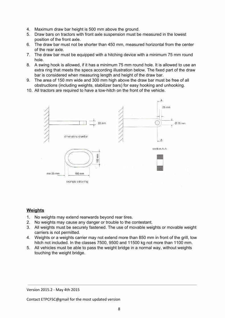
of the rear axle. 7. The draw bar must be equipped with a hitching device with a minimum 75 mm round
hole. 8. A swing hook is allowed, if it has a minimum 75 mm round hole. It is allowed to use an
extra ring that meets the specs according illustration below. The fixed part of the draw bar is considered when measuring length and height of the draw bar.
9. The area of 150 mm wide and 300 mm high above the draw bar must be free of all obstructions (including weights, stabilizer bars) for easy hooking and unhooking.
10. All tractors are required to have a towhitch on the front of the vehicle. Weights
1. No weights may extend rearwards beyond rear tires. 2. No weights may cause any danger or trouble to the contestant. 3. All weights must be securely fastened. The use of movable weights or movable weight
carriers is not permitted. 4. Weights or a weights carrier may not extend more than 850 mm in front of the grill, tow
hitch not included. In the classes 7500, 9500 and 11500 kg not more than 1100 mm. 5. All vehicles must be able to pass the weight bridge in a normal way, without weights
touching the weight bridge.
Version 2015.2 - May 4th 2015
Contact ETPCFSC@gmail for the most updated version
8
Chapter 2 Level 2 Sport Classes Definition Sport classes are RPM limited classes where modifications to increase the horsepower are allowed. When using an intercooler, they have to have an air restrictor. No intercooler allowed under 3500kg. General Rules, apply to all tractors 1. The basis of the tractor must come from a front wheel steered standard tractor. The
combination of engine, bell housing, transmission and rear end must have been sold at least 150 times. The tractor must maintain its original factory appearance. There must not be a visible part in the drive line that is of another brand. (For example, you must not mix a JD back end with an IH engine).
2. The motor with cylinder head must externally be original from the manufacturer. These must have the original dimensions and must have been used in a front wheel steered agricultural tractor.
3. It is allowed to change the cylinder head, providing the change was made on the original motor block in production. Length, width and height must remain the original measurements. It must also be possible to fit the inlet and exhaust manifolds in the same position as the original. It is not allowed to add extra inlet and outlets.
4. Injection pump and camshaft have to be driven the original way. Different flanges, extensions or turning round of the injection pump are allowed.
5. The use of another sump is allowed, providing it is not part of the carrying structure in frame less tractors. It must be possible to replace the original sump on the motor block in its original position.
6. A girdle under the motor block is allowed, and falls under the same rules as the sump. 7. The use of another rocker cover is allowed. It must be possible to replace the original
rocker cover on the cylinder head in its original position. 8. It is allowed to update to an older or newer style of hood and panel work. 9. Overhead camshafts are only allowed if the engine came with it from the factory. 10. The use of a spacer between the motor block and bell housing is allowed, with a
maximum width of 35mm ( e.g to put in a multiple disk clutch). The spacer must have the same bolt pattern as the engine and bell housing.
11. The drive line, existing of motor, bell housing, gearbox and rear axle, must hold without external strengthening. Connecting plates, flanges or weldedon parts are not allowed. If the engine and bell housing do not form one unit in the original tractor, the tractor must have a self carrying frame (according to the rules in Level 3).
12. The mounting of maximum one (1) turbocharger, consisting of inlet and exhaust, is allowed.
13. The conversion from fourstroke to twostroke is not allowed. 14. The only legal fuel is diesel. Oxygen carriers and combustion accelerators are illegal.
Diesel fuel is defined by the ETPC as a pure hydrocarbon. The ETPC will evaluate diesel fuel using the dielectric constant value. That value shall be determined by the ETPCapproved fuel check meter only. The fuel check meter shall use cyclohexane to
Version 2015.2 - May 4th 2015
Contact ETPCFSC@gmail for the most updated version
9
establish the zero reference point for determine all diesel fuel dielectric constant values. Diesel fuel to be used in ETPC sanctioned events shall have a dielectric value of no greater than 4.9, nor a value of no less than 2.0. The use of additives containing oxygen, such as nitro methane, propylene oxide, dioxide, MTBE, alcohol or nitrous oxide, are strictly prohibited. These additives, and others of the oxygenbearing family, will significantly change the dielectric constant value of any diesel fuel. Diesel fuel with dielectric constant values that fall outside the ETPCstandards will not be allowed for use in ETPC competition. It is prohibited other fluids, fuels or gasses to add, inject or spray in or on any part of the tractor. Water injection is not allowed. The ETPC keeps the right to decide that the fuel that has to be used for the competition will be supplied thought the ETPC. Water injection is not allowed.
15. The maximum wheel base in 2500kg class is limited to 2600mm. In all other classes 2900mm.
16. The maximum length measured from the middle of the rear wheel of the tractor in 2500kg class is 3500mm. In all other classes 4000mm. The towing hitch, with maximum length 150mm, is not measured in the maximum length, it may be additional.
17. Advertising boards are allowed, providing they do not influence the visibility of the driver. They may not extent over the sides.
18. European John Deere heads are allowed to machine the inlet manifold housing off, to the line of the valve cover.
19. If the ETPC or national organization doubts the legality of any entry, or upon protest by another contestant in that class, contestant in question must verify that 150 units of the tractor in question have been manufactured (notarized statement from the manufacturer), furnish parts numbers, and prove to the Board’s satisfaction that the tractor is legal.
Performance rules Sport Class 1. The fitting of an intercooler is allowed in all classes except the 2500kg class. 2. Electronically controlled injection systems are allowed. 3. The tractors with 2500kg must have a turbo inlet of max 55mm, or an air restrictor tube
with a max inner diameter of 55mm or max 57mm outer diameter, with 20mm measurable distance, mounted in front of the turbo and all air going to the turbo must flow through the tube.
4. The tractors with 3500kg and more must have a turbo inlet of max 68mm, or an air restrictor tube with a max inner diameter of 68mm or max 70mm outer diameter, with 20mm measurable distance, mounted in front of the turbo and all air going to the turbo must flow through the tube.
5. In the 3500kg Level 2 Sports class, within 70mm in front of the 68mm zone it’s not allowed to have any tubes, venturis or funnels smaller than 100mm diameter . The area before the 68mm may be open (e.g. a flat plate, 20mm thick). The area behind the 20mm long tube (to turbo) is free of choice. Refer to the following drawing. The Air Shut off may be placed directly in front of the restrictor, but must not have any ventury or funnel style design.
Version 2015.2 - May 4th 2015
Contact ETPCFSC@gmail for the most updated version
10
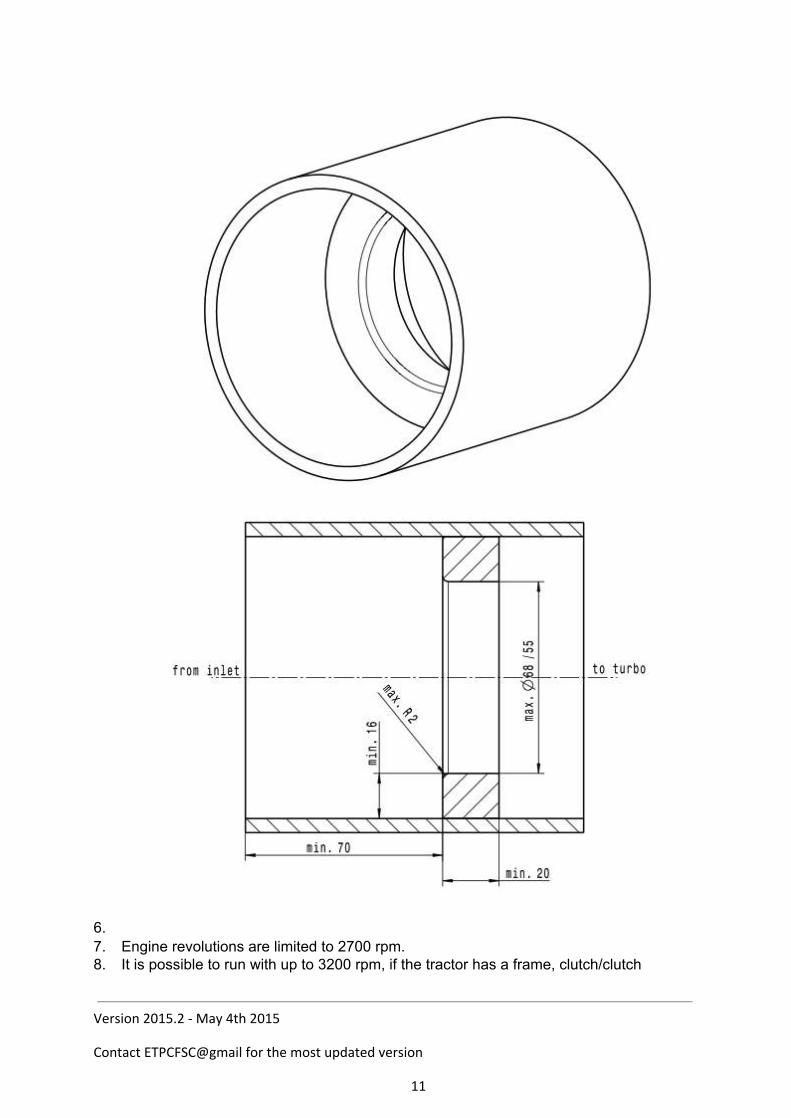
6. 7. Engine revolutions are limited to 2700 rpm. 8. It is possible to run with up to 3200 rpm, if the tractor has a frame, clutch/clutch
Version 2015.2 - May 4th 2015
Contact ETPCFSC@gmail for the most updated version
11
protection and cable around the engine according to the Level 3 rules. 9. Weight classes are
2500 kg 3500 kg 4500 kg 5500 kg 6500 kg
Note: Additional pump or engine displacement limits in the sports classes are a concern of the ETPC member countries. In national competitions those rules have to be followed by foreign competitors. International ETPC competitions (EuroChallenge) however will not have other pump rules than stated above, nor will the size of the engine be taken into consideration. The air restrictor is considered the “equalizing” factor.
Safety rules 1. All tractors must have an rpm measuring point. This consists of a reflective sticker
of size 30mm x 30mm. It must be on an easily accessible point on the front of the engine. It must be possible to measure the RPM within three minutes; otherwise the competitor will be disqualified. Measuring will take place with a noncontact tachometer.
2. If the on board rpm measuring devices of a national association is used, it is recommended to use two signals per revolution for good measurement. A single signal per revolution is not considered accurate enough to base decisions upon.
3. Only mechanical activated clutches permitted. No electronic, pneumatic or hydraulic device that effects the clutch system allowed. Hydraulic engagement allowed. Other clutch systems are only allowed, if the original tractor was fitted with them.
4. The driver must wear good work clothes (tight cotton) on the whole body covering complete arms and legs and closed shoes (no sandals).
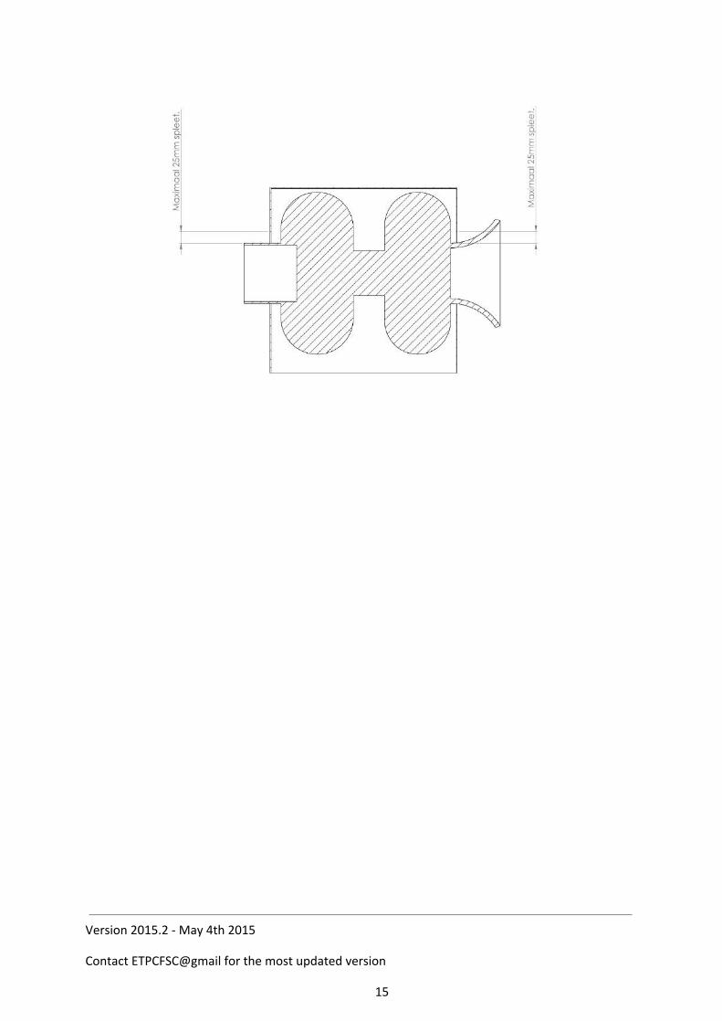
5. Turbo shielding: Turbocharger with exhaust outlet up to 95 mm. diameter All turbochargers must be completely shrouded (360 degrees), except for inlet and exhaust and supply pipes with 2mm steel. any openings in the guarding around inlet/exhaust/oil supply pipes can have a max. of 25 mm clearance to the guarding.(drawing 1) Front (inlet)and rear (exhaust) end of guarding must be closed with 2mm steel. The guarding must ensure that no wheels or other parts of the turbocharger can come out in case of a turbocharger explosion. The guarding must be mounted as close as possible to the turbocharger, at min. four (4) points with min. M8 8.8 bolts. (connection to inlet or exhaust pipe is not seen as connection point) Around every bolt hole must be min. 1.5 x hole diameter of material. Guarding must extend until cross in exhaust. Hood construction or grille cannot be part of the shielding.
Version 2015.2 - May 4th 2015
Contact ETPCFSC@gmail for the most updated version
12
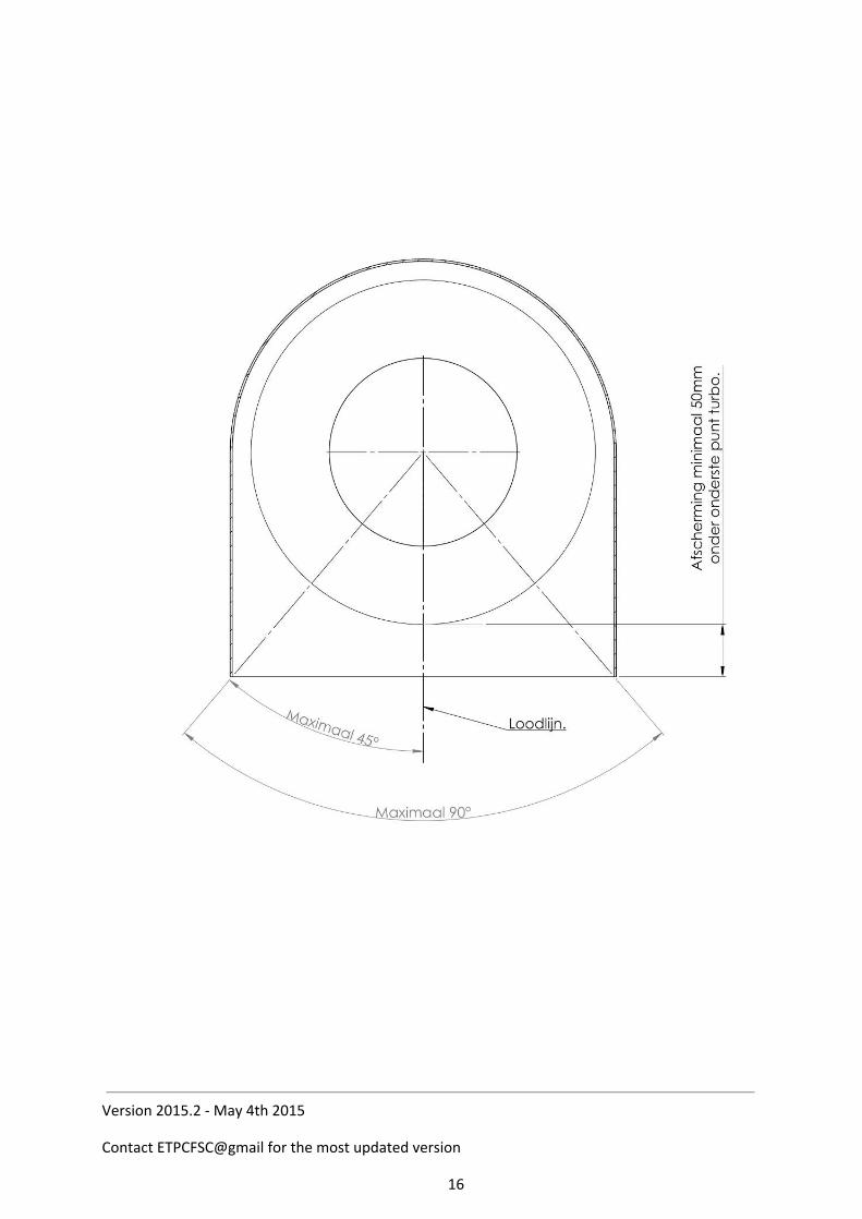
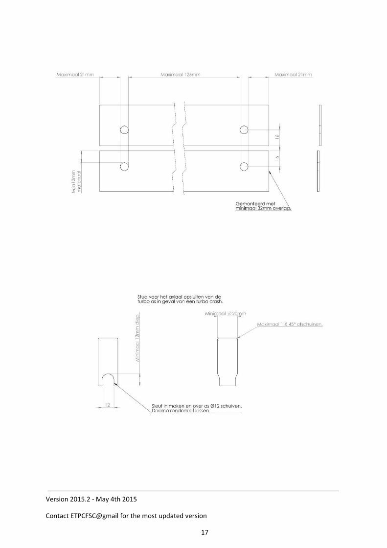
For tractors with a closed hood construction (min 2mm steel or min. 3mm aluminum), an open bottom to guarding with max. 90 degrees of the radial part is allowed. Open bottom shielding must extend at least 50 mm. below the bottom of the turbocharger. ( drawing 2). If turbo protection is made out of separate parts welds must be full length or 360 degrees round. In case of a bolted construction there must be min. M8 8.8 bolts used, placed at maximum of 75mm centres. Distance from bolt location to edge of the shielding or plate maximum 25 mm. Around every bolt hole must be minimum 1.5x hole diameter of material. Minimum overlap of material 32mm. ( drawing 3) Exhaust pipe must have a steel cross as close as possible to the turbo exhaust housing outlet, but maximum 50 mm. from turbo exhaust wheel. Cross to be made from min.10 mm. diam. steel pin. (compact diesel:min. 8mm.diameter) Pins to be installed 90 degrees to each other , as closes as possible to each other. If exhaust pipe has a diameter larger than 95mm there must be a third pin of 10 mm maximum 50 mm from cross.(pin every 60 degrees) If exhaust pipe has a diameter larger than 160 mm there must be a fourth pin of 10 mm diam. max. 50 mm from cross. (pin every 45 degrees) Maximum diameter of exhaust pipe allowed is 200mm. Pins must have 5mm. visible on the outside of the exhaust pipe and be welded to the pipe. From cross to turbo exhaust wheel there must be an axial stud minimum 12mm diameter. Welded to the cross. Max. distance between axial stud and turbo exhaust wheel is 2mm. Wall thickness of exhaust pipe from turbo to cross min 4 mm. ( drawing 4) If it is not possible to use the 10mm pins , 25x5 mm. flat steel may be used as the cross. This cross must also follow the above rules concerning the stud and the 5mm visible on the outside plus the welding’s on the outside, and 3th. and 4th flat steel by bigger diameter pipe. Flat steel can only be used after written approval of the National and the ETPC T&S board. Exhaust pipe must have 3 additional connections to the exhaust protection to prevent pipe coming loose from turbo (if clamp fails or breaks) Connections made from min. 25x5 flat steel inside the turbocharger guarding. 25x5 flat steel to be connected with min. M8 8.8 bolts to guarding Around every bolt hole must be min. 1.5 x hole diameter material.(drawing 5) B. Turbocharger with exhaust outlet above 95 mm and up to 112 mm diameter As per rules for turbochargers with exhaust outlets up to 95 mm but with the following differences:
Version 2015.2 - May 4th 2015
Contact ETPCFSC@gmail for the most updated version
13

Cross pins to be made from 12 mm diameter (not 10 mm) Axial stud to be made from 20 mm diameter (not 12 mm) C. Turbochargers with exhaust outlet above 112 mm and up to 132 mm diameter As per rules for turbochargers with exhaust outlet up to 95 mm but with the following differences: Cross pins to be made from 12 mm diameter (not 10 mm) Axial stud to be made from 20 mm diameter (not 10 mm) By one stage turbocharged diesel engines the following stronger shielding: All turbochargers must be completely shrouded (360 degrees), except for inlet, exhaust and oil supply pipes with 3mm steel. (radial part: pipe or rolled steel section) Any openings in the guarding around inlet/exhaust/oil supply pipes can have a maximum of 25 mm. clearance to the guarding. The turbocharger guarding must also cover the first cross in the exhaust outlet. Axial: front (inlet) and rear (exhaust) end of guarding must be closed with 6mm steel. (not 3mm) Guarding may be divided axially, on these separate axial parts a 6mm plate must be full welded and then bolted together with the second part with minimum M8 8.8 bolts, with maximum distance bolt to bolt of 50 mm. Minimum 5.5 mm material around bolt hole. Around the exhaust pipe there must be a fixed ring or plate of min. 6mm thick. The ring must be connected on the inside of the rear end of guarding. Ring or plate must have 30 mm larger diameter than the hole in rear part of guarding, this is to prevent the exhaust and cross with axial stud is coming loose from turbocharger. (drawing 6) If turbocharger guarding cannot be made according specifications above, engine or chassis. Chassis may be part of guarding, only after written approval of the Nat. and ETPC T&S board after written approval of the National and the ETPC T&S board. Above turbocharger shielding must be yearly inspected and stamped. Inspection paper and photo must be filed and a copy must be with the vehicle at all times for inspection.
Version 2015.2 - May 4th 2015
Contact ETPCFSC@gmail for the most updated version
14
Version 2015.2 - May 4th 2015
Contact ETPCFSC@gmail for the most updated version
15
Version 2015.2 - May 4th 2015
Contact ETPCFSC@gmail for the most updated version
16
Version 2015.2 - May 4th 2015
Contact ETPCFSC@gmail for the most updated version
17

Version 2015.2 - May 4th 2015
Contact ETPCFSC@gmail for the most updated version
18
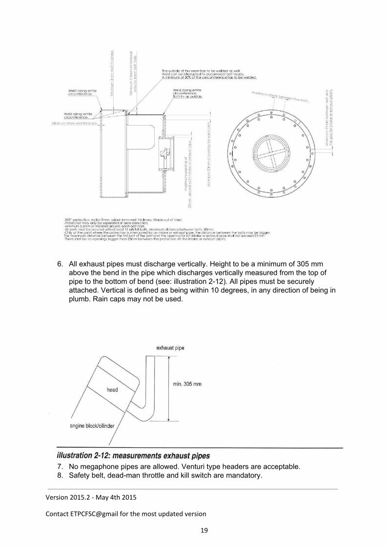
6. All exhaust pipes must discharge vertically. Height to be a minimum of 305 mm
above the bend in the pipe which discharges vertically measured from the top of pipe to the bottom of bend (see: illustration 212). All pipes must be securely attached. Vertical is defined as being within 10 degrees, in any direction of being in plumb. Rain caps may not be used.
7. No megaphone pipes are allowed. Venturi type headers are acceptable. 8. Safety belt, deadman throttle and kill switch are mandatory.
Version 2015.2 - May 4th 2015
Contact ETPCFSC@gmail for the most updated version
19
9. A safety belt (minimum lap belt) must be fastened before the start. 10. All deadman throttles working in a forwardsrearwards direction shall be closed in
the rearmost position. Must be positive, two way, mechanical linkage. All foot throttles must have a toe strap. No hydraulic throttle linkage allowed.
11. All engines must have a visible returntoidle spring on fuel injection pump lever. 12. The tractor must be fitted with an approved roll over protection: A factory ROP, a
safety cab, an ETPC ROP or ETPC – roll bare. 13. If an ETPC ROP is fitted, fireproof clothing, helmet, min. fourpoint harness,
firewall between the engine compartment and driver, and ETPC chassis support (help frame) are obligatory. The specific information can be found in the rules of level 3.
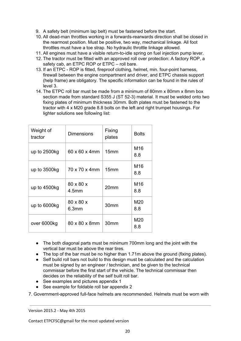
14. The ETPC roll bar must be made from a minimum of 80mm x 80mm x 8mm box section made from standard S355 J (ST 523) material. It must be welded onto two fixing plates of minimum thickness 30mm. Both plates must be fastened to the tractor with 4 x M20 grade 8.8 bolts on the left and right trumpet housings. For lighter solutions see following list:
Weight of tractor
Dimensions Fixing plates
Bolts
up to 2500kg 60 x 60 x 4mm 15mm M16 8.8
up to 3500kg 70 x 70 x 4mm 15mm M16 8.8
up to 4500kg 80 x 80 x 4.5mm
20mm M16 8.8
up to 6000kg 80 x 80 x 6.3mm
30mm M20 8.8
over 6000kg 80 x 80 x 8mm 30mm M20 8.8
The both diagonal parts must be minimum 700mm long and the joint with the vertical bar must be above the rear tires.
The top of the bar must be no higher than 1.71m above the ground (fixing plates). Self build roll bars not build to this design must be calculated and the calculation
must be signed by an engineer / technician, and be given to the technical commissar before the first start of the vehicle. The technical commissar then decides on the reliability of the self built roll bar.
See examples and pictures appendix 1 See example for foldable roll bar appendix 2
7. Governmentapproved fullface helmets are recommended. Helmets must be worn with
Version 2015.2 - May 4th 2015
Contact ETPCFSC@gmail for the most updated version
20
chin strap fastened when pulling.
Engine protection 1. Engine protection is required on all vehicles, by means of a side panel on both sides of
the engine. The side panel must cover the total length and height of the motor block and be fastened securely in four places. It must be made from aluminum or steel sheet minimum thickness 2mm. The side shields must be one piece – no sandwiches. The protection for all inline engines is from the engine hood until 50mm under the bottom point of the crankshaft journals. The fastening of the side panels must be strong enough to hold them in position in the event of an explosion. The side panels on all Vengines must be from the top edge of the cylinder head or topdeadcenter of the piston until 50mm under the bottom point of the crankshaft journals. The side panel is not allowed to be fixed to the motor block. Fastening to the engine mount, cylinder head, traverses or chassis is allowed.
2. All engine fans must be radially shrouded 360 degrees, with steel 2 mm or thicker, electric fans excluded.
3. All inter coolers located outside of the engine shielding must be shielded with steel 2 mm thick or greater.
Kill switch 1. All kill switches must be mounted independent of drawbar and or stabilizer bars. 2. All pulling vehicles must have an automatic ignition kill switch and / or air shutoff, in
working order at all times. The kill switch device must also work in a situation where the electric circuit of the vehicle is interrupted. Every kill switch must generally work according to the fail safe principle. This means no situation whatsoever may cause the kill switch to go out of function. Track Officials and/or Tech Inspectors have the option of checking the kill switches as many times as they feel adequate at any event. The switch must be checked with the engine running.
3. The kill switch on all tractors must be located in the rear center of the vehicle (maximum of 150 mm off center in any direction), 1200 mm above the point of hook.
4. The kill switch must activate the air shutoff. A cable may be used for this purpose, but the flap must have a springloaded closing mechanism. A system to be deemed acceptable must at least prevent the building of boost. A hole with a maximum diameter of 25 mm in the flap is allowed. It is recommended that a gasket/seal arrangement is used to shut off the air flow more effectively. All diesel engines must be equipped with an emergency shut down air shut off at the air intake, which can be utilized from the driver’s seat. On tractors with an electric kill switch system, the solenoids holding the flap up must have a positive (+) connection through the kill switch. The use of solenoids or electric motors that need voltage in order to activate the flap is not allowed. Also, systems that need air pressure to activate the kill switch are not permitted.
5. The breakaway kill switches must have a 50mm diameter ring attached The cable from the sled will be attached to this ring. The kill switch ring or cable ‘ring’ must be secured with a nylon tie wrap (1/8 inch). The tie wrap must be broken for a repull. ETPC and affiliated organizations will supply the tie wraps for uniformity.
6. If a vehicle has a kill switch or shut off in legal position and during the pull the kill
Version 2015.2 - May 4th 2015
Contact ETPCFSC@gmail for the most updated version
21
switch is pulled and the nylon strap is broken and the presiding official inspects and finds the switch capable of operating properly under normal conditions, the vehicle will be allowed to repull immediately, or drop six positions. The decision to drop must be made before vehicle leaves the track. It is the puller’s responsibility to see whether the kill switch is working.
7. The force which is necessary to pull the kill switch must not be more than 10 kilo. 8. All tractors must have a fuel shut off valve control within easy reach of the driver (a fuel
shutoff valve on the diesel pump will do). 9. A tractor must be equipped with an emergency shutdown air shutoff at the airintake,
which can be utilized from the driver’s seat. 10. Onboard batteries must be securely fastened and properly covered to prevent any
sparks. Especially, any possibility of them getting into contact with the kill switch cable from the sled must be avoided.
Version 2015.2 - May 4th 2015
Contact ETPCFSC@gmail for the most updated version
22
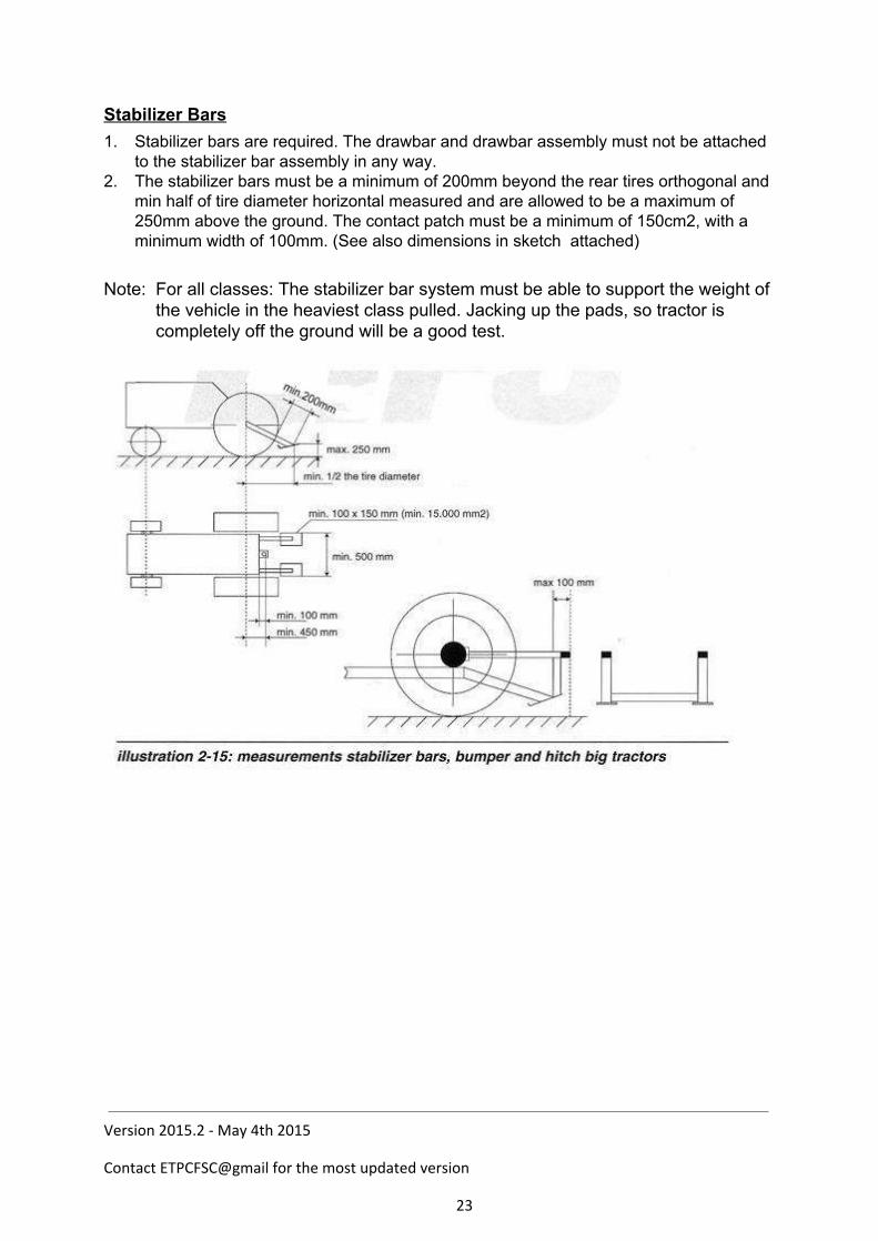
Stabilizer Bars 1. Stabilizer bars are required. The drawbar and drawbar assembly must not be attached
to the stabilizer bar assembly in any way. 2. The stabilizer bars must be a minimum of 200mm beyond the rear tires orthogonal and
min half of tire diameter horizontal measured and are allowed to be a maximum of 250mm above the ground. The contact patch must be a minimum of 150cm2, with a minimum width of 100mm. (See also dimensions in sketch attached)
Note: For all classes: The stabilizer bar system must be able to support the weight of
the vehicle in the heaviest class pulled. Jacking up the pads, so tractor is completely off the ground will be a good test.
Version 2015.2 - May 4th 2015
Contact ETPCFSC@gmail for the most updated version
23

Seats and fenders 1. All tractors must have a stable and tightly fastened driver’s seat with a back rest. All
folding seats must be fastened securely during a pull. 2. All tractors must have a shield between the driver and the tires consisting of a solid
barrier between driver and any part of the rear tires, which is able to sufficiently support the weight of the driver. It must be fitted with a fender construction, stable enough to take the weight of the driver.
RPM control
1. It is strongly recommended to measure engine RPM during the run. Every tractor must be equipped with a 3pole socket (DIN 9680, Hella No. 8JB 001 933011 / John Deere No. AZ 54775 / Jaeger No. 151130) near the kill switch ring. A magnetic sensor (e.g. Pepperl & Fuchs No. NBB412GM30E2V1) must be placed at a crank pulley and pick up the signals of two M12 bolts in the pulley (see drawing below). The wire attachment to the socket is: Brown = + Blue = Black = Sensor
ATTN: Some national circuits (Netherlands, ?) only measure with one bolt (one pulse per revolution). Ask before you hook outside of your home circuit and be prepared to take one bolt out before running.
Version 2015.2 - May 4th 2015
Contact ETPCFSC@gmail for the most updated version
24
Tires 1. Tractors are only allowed to drive with rubber tires; chains or similar are not allowed.
All tires are allowed to be cut. Dual tires are not allowed. 2. The total width of the tractor is maximum 3000mm. This will be measured at the axle
height. 3. The maximum allowed tire width is 30.5“ inch, or 800mm. The maximum diameter of
wheel rims is 32” inch. If the width of the tires is less than or equal to 710mm, a wheel rim diameter of 42” inch is allowed. The manufacturer’s markings on the tires state the tire dimensions. Puller tires are allowed
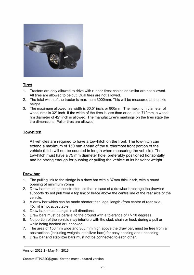
Towhitch
All vehicles are required to have a towhitch on the front. The towhitch can extend a maximum of 150 mm ahead of the furthermost front portion of the vehicle (hitch will not be counted in length when measuring the vehicle). The towhitch must have a 75 mm diameter hole, preferably positioned horizontally and be strong enough for pushing or pulling the vehicle at its heaviest weight.
Draw bar 1. The pulling link to the sledge is a draw bar with a 37mm thick hitch, with a round
opening of minimum 75mm 2. Draw bars must be constructed, so that in case of a drawbar breakage the drawbar
supports do not pull from a top link or brace above the centre line of the rear axle of the vehicle.
3. A draw bar which can be made shorter than legal length (from centre of rear axle: 45cm) is not acceptable.
4. Draw bars must be rigid in all directions. 5. Draw bars must be parallel to the ground with a tolerance of +/ 10 degrees. 6. No portion of the vehicle may interfere with the sled, chain or hook during a pull or
while being hooked or unhooked. 7. The area of 150 mm wide and 300 mm high above the draw bar, must be free from all
obstructions (including weights, stabilizer bars) for easy hooking and unhooking. 8. Draw bar and stabilizer bars must not be connected to each other.
Version 2015.2 - May 4th 2015
Contact ETPCFSC@gmail for the most updated version
25
9. The draw bar distance from center of rear axle must not change during pull. Note: The ETPC highly recommends competing vehicles not to be tied down to a
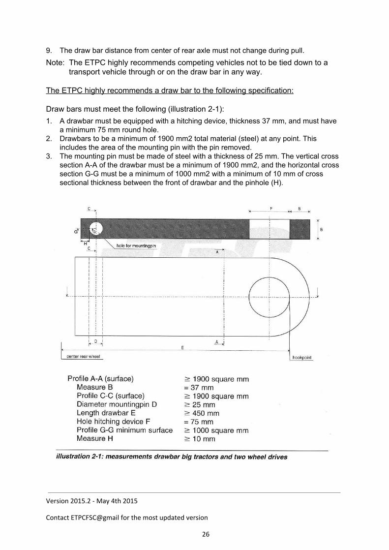
transport vehicle through or on the draw bar in any way. The ETPC highly recommends a draw bar to the following specification: Draw bars must meet the following (illustration 21): 1. A drawbar must be equipped with a hitching device, thickness 37 mm, and must have
a minimum 75 mm round hole. 2. Drawbars to be a minimum of 1900 mm2 total material (steel) at any point. This
includes the area of the mounting pin with the pin removed. 3. The mounting pin must be made of steel with a thickness of 25 mm. The vertical cross
section AA of the drawbar must be a minimum of 1900 mm2, and the horizontal cross section GG must be a minimum of 1000 mm2 with a minimum of 10 mm of cross sectional thickness between the front of drawbar and the pinhole (H).
Version 2015.2 - May 4th 2015
Contact ETPCFSC@gmail for the most updated version
26
Weights
1. No weights may extend rearwards beyond the rear tires 2. All weights must be securely fastened. 3. Any ballast lost while hooked to the sled and under the green flag will be a cause for
disqualification (internal breakage excepted). 4. The use of movable weights or movable weight carriers is not permitted. 5. No weights allowed higher than 300 mm above the center line of the rear axle. 6. Weights are not allowed to make contact to the ground, even if fastened. 7. The competitor must be able to cross the weighbridge without contacting the
weighbridge with his weights. Legality 1. If the ETPC or national organization doubts the legality of any entry, or upon protest by
another contestant in that class, contestant in question must verify that 150 units of the tractor in question have been manufactured (notarized statement from the manufacturer), furnish parts numbers, and prove to the board’s satisfaction that the tractor is legal.
2. Engine manufacturer must fit the hood 3. The combination of engine, bellhousing/transmission and rearend must have been
manufactured in that combination (but not necessarily with that brand of hood).
Version 2015.2 - May 4th 2015
Contact ETPCFSC@gmail for the most updated version
27
Chapter 3 Level 3 Super Sport / Farm Stock Classes
Definition Sport and Supersport/Farm Stock classes are RPM limited classes, where modifications to increase the horsepower are allowed. A tractor according to the Level 3 safety, may compete under the engine limits of the next heavier Level 2 class. Brakes
1. All competing vehicles must be equipped with working rear brakes. Towhitch
1. All vehicles are required to have a towhitch on the front of their vehicle. The towhitch can extend a maximum of 150 mm ahead of the furthermost front portion of the vehicle (hitch will not be counted in length when measuring the vehicle). The towhitch must have a 75 mm diameter hole, preferably positioned horizontally, and be strong enough for pushing or pulling the vehicle at its heaviest weight.
Drawbars
1. The pulling link to the sledge is from a draw bar with a 37mm thick hitch, with a round opening of minimum 75mm
2. Draw bars shall be constructed, so that in the event of a drawbar breakage the drawbar supports do not pull from a top link or brace above the centerline of the rear axle of the vehicle.
3. A drawbar which can be made shorter than legal length (from centre of rear axle: 45cm) is not acceptable.
4. Drawbars must be rigid in all directions. 5. Drawbars must be parallel to the ground with a tolerance +/ 10 degrees. The front axle
suspension must be totally lowered, if this is possible from the manufacturer. 6. Drawbars and hitching devices must be made out of solid steel with a minimum of 520
N/mm2 tensile strength in all weight classes. No welding on drawbars. 7. No portion of the vehicle may interfere with sled, chain or hook, during a pull or while
being hooked or unhooked. 8. An area of 150 mm wide and 300 mm high, immediately above the draw bar, must be
free from all obstructions (including weights, stabilizer bars) for easy hooking and unhooking.
9. Draw bar and stabilizer bars must not be connected to each other. 10. The drawbar distance from center of rear axle cannot change during pull. Note: The ETPC highly recommends that competing vehicle should not be tied up down to a tow vehicle through or on the drawbar in any way.
Version 2015.2 - May 4th 2015
Contact ETPCFSC@gmail for the most updated version
28
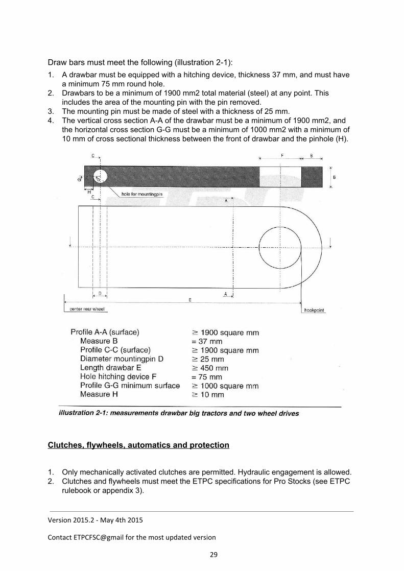
Draw bars must meet the following (illustration 21): 1. A drawbar must be equipped with a hitching device, thickness 37 mm, and must have
a minimum 75 mm round hole. 2. Drawbars to be a minimum of 1900 mm2 total material (steel) at any point. This
includes the area of the mounting pin with the pin removed. 3. The mounting pin must be made of steel with a thickness of 25 mm. 4. The vertical cross section AA of the drawbar must be a minimum of 1900 mm2, and
the horizontal cross section GG must be a minimum of 1000 mm2 with a minimum of 10 mm of cross sectional thickness between the front of drawbar and the pinhole (H).
Clutches, flywheels, automatics and protection
1. Only mechanically activated clutches are permitted. Hydraulic engagement is allowed. 2. Clutches and flywheels must meet the ETPC specifications for Pro Stocks (see ETPC
rulebook or appendix 3).
Version 2015.2 - May 4th 2015
Contact ETPCFSC@gmail for the most updated version
29
3a. Engines limited up to 2.700 rpm must have either: 1. A one piece steel tube, 10mm thick around the clutch inside the bellhousing 2. An ETPC approved shatter blanked (See ETPC rulebook or appendix 3 and 4) 3. An ETPC approved bell housing (See ETPC rulebook or appendix 3 and 4)
3b. Engines limited up to 3.200 rpm must have either:
1. An ETPC approved shatter blanked (See ETPC rulebook or appendix 3 and 4) 2. An ETPC approved bell housing (See ETPC rulebook or appendix 3 and 4)
Shatter blankets 1. Shatter blankets must be on the inside of the tie bars or one piece frame and the tie
bars must be fastened forward of the rear of the engine block. However, in some occasions there is no space for the blanket inside the tie bar or the one piece frame, in that case a written approval from ETPC or affiliated organization must be available to Tech Inspectors.
Chassis It shall consist of the following: 1. The stock engine block or OEM engine block that will operate with the stock crankshaft
for that model without any alterations for chassis mounting. 2. Engine block must remain in original location as located by manufacturer. 3. All engines must be secured and held rigid to OEM chassis. Engine cannot move
independent or rear end/transmission housing. 4. The stock transmission housing or manufacturer’s replacement and the stock final
drive housing or manufacturer’s replacement. Planetaries are considered part of final drive and are not removable.
5. The OEM engine block cannot be modified externally, except for normal repair or for mounting of fuel injection equipment.
6. Internal webbing and water jacket must remain intact with provisions to rebore engine block.
7. Any alterations to the chassis shell must have the written approval of the ETPC and the national Tech and Safety Board (TSB), before the tractor in question will be considered legal.
8. The chassis and frame must remain stock from the rear of the engine block to the rear of the tractor.
9. The only vehicles that are considered legal in supersport / farmstock classes are those that are available as farm tractors with front wheel steering.
10. The clutch housing, transmission case, rear end housing and axle housing must be OEM, with no aluminum replacements.
11. The use of a spacer between engine block and bellhousing is allowed with a maximum additional thickness of 35 mm. An aluminum spacerplate cannot be part of the clutch protection.
12. There must not be a visible part in the drive line that is of another brand. 13. The drive line, made up of motor, bell housing, gearbox and rear axle, must hold
without external strengthening. Connecting plates, flanges or weldedon parts are not
Version 2015.2 - May 4th 2015
Contact ETPCFSC@gmail for the most updated version
30

allowed, except if engine and bell housing do not form one unit in the original tractor. In that case the tractor must have a self carrying frame (refer to point Frame/sheetmetal below).
14. Advertising boards are allowed, providing they do not influence the visibility of the driver. They may not extent over the sides.
Frame/sheetmetal 1. Tractor must have hood and grill in place as intended by the manufacturer. 2. Sheetmetal can be up/down graded to present/past manufacturer by approval of ETPC
and national TSB. 3. Sheetmetal to be stock length and in stock location. 4. Tractor must retain stock appearance. 5. The distance form center of the rear axle to that part of the hood that is farthest forward
must be the same length as that model of the upgraded sheetmetal. 6. Wheelbase rule will apply according to the original chassis, not to the model of the
upgraded sheetmetal. 7. Maximum of 2900 mm wheelbase unless originally produced with longer wheelbase, in
which case stock length must remain. Maximum length of 4000 mm from center of rear wheel to forward most portion including weights and weight racks.
8. The total width of the tractor is maximum 3000mm. This will be measured at axle height.
9. supersport / farmstock chassis rules A: 18 above will apply according to the original chassis, not to the model of the upgraded sheetmetal.
Frame options 1. Tractor must have either
a. Safety tie bars made out of steel mounted to rear axle housing with at least four (4) axle housing bolts and extending forward of flywheel area and fastened to side of engine block or main frame with at least three (3) 14 mm steel bolts grade 8.8 (See illustration 41)
Version 2015.2 - May 4th 2015
Contact ETPCFSC@gmail for the most updated version
31
or b. a one piece frame extending from front of tractor to rear axle housing mounting bolts.
or c. a divisible frame under the following conditions:
The steel splitframe construction must extend from front of tractor to rear axle housing mounting bolts.
The two pieces have to fit in one another (sliding in construction) in the area where the tractor can be split (clutch area).
The two pieces of the frame must be made of tubes or ushaped steel with a thickness of at least 3 mm.
If the frame is made of ushaped steel It must have a ushaped connection bar inside min. 500 mm length. (250 mm in the rear part and 250 mm in the front part of the ushaped split frame).
If the frame is made out of tubes it must have inner tubes min. 500 mm length. (250 mm in the rear part and 250 mm in the front part of the tubeframe).
Rear part of the frame hast to be mounted to rearaxle housing with at least four (4) axlehousing bolts and extending forward of flywheel area and fastened to side of engine block or motorplate with at least three (3) 14 mm bolts min. grade 8.8.
Two parts of frame must be locked together with at least two (2) fasteners of 8 mm steel.
Two piece frame must be of sufficient strength to support weight of tractor with the bolts used to split the tractor removed.
2. Tie bars or frame must be of sufficient strength to support weight of tractor with the bolts used to split the tractor removed.
Limits 1. 3,6 ton:
a. engine size max. 7.000 cm3, max. 6 cylinders with turbo charger, rpm: max. 2700. b. engine size max. 6.063 cm3, with turbo charger, rpm: max. 3200. c. Maximum two valves per cylinder allowed.
2. 4,5 ton: a. engine size max. 9.000 cm3, max. 8 cylinders with turbo charger, rpm: max. 2700. a. engine size max. 8.364 cm3, with turbo charger, rpm: max. 3200. b. Maximum two valves per cylinder allowed.
Engines
Version 2015.2 - May 4th 2015
Contact ETPCFSC@gmail for the most updated version
32
1. Supersport / farmstock are limited to one (1) pressure stage with turbo chargers. No mechanical blowers / superchargers.
2. Engine head must be OEM agricultural type for that brand engine. 3. Supersport under 2700 rpm may have one (1) fuel injection pump of any size, only
one (1) pump element per cylinder allowed. If using OEM (available of parts counter) 12 cylinder fuel injection pump two (2) pumpelements per cylinder allowed. Note: no pump limits after 01012014.
4. Farm Stock tractors under the 3200 rpm limit must us a P Pump with a max of 13mm Plungers and a max of one plunger per cylinder. Note: no pump limits after 01012014.
5. Diesel fuel only. Inter cooler allowed. Use of gasohol and/or alcohol is prohibited. 6. No overhead camshafts allowed. 7. Conversion from 4stroke into 2 stroke principle is not allowed. 8. No deck plate when the engine is downsized. Otherwise a deck plate is allowed.
The maximum distance between the center line of the crankshaft and the top of the engine block, including deck plate and gasket material is 410mm.
9. One piece engine main cap bearings allowed. One piece main cap not considered as a girdle.
10. Injection pump and camshaft have to be driven the original way. Different flanges, extensions or turning the injection pump around are allowed.
11. The use of another sump is allowed, providing it is not part of the carrying structure in frameless tractors. It must be possible to replace the original sump on the motor block in its original position.
12. A girdle under the motor block is allowed, same requirements like for the sump. 13. The use of another rocker cover is allowed. It must be possible to replace the
original rocker cover on the cylinder head in its original position. 14. The competitor needs to drill two holes of (3.5 mm) into two bolts (next to each
other) of the sump. These holes can be used to seal the engine. 15. European John Deere heads are allowed to machine the inlet manifold housing off,
to the line of the valve cover. Engine shielding
1. A deflection shield is required on both sides of all engines. Shield must extend the complete length of block casting and be securely fastened. It has to be made of aluminum or steel, minimum thickness 2 mm. Shields must be solid. Motor mounts, filters, steering rods, etc. cannot serve as part of shield. Solid frame rails with no holes can serve as part or all of shield, providing it covers required areas of block casting. It is recommended that quick release fasteners are used (winged Dzus type or cotter pin type hoop pins). Use of bolts with nuts, screw locks are undesired. (reason: ease of access in case of emergencyfire, run off, etc).
2. Shielding on all tractors with in line engines must be from sheet metal (hood) to 50 mm below bottom center of crankshaft throw, and be securely fastened. They may be louvered, but no expanded metal. Fastening of hood and side shielding must be strong enough to keep them in place in case of an explosion.
3. Starter motors, fuel filters, oil filters and fuel injection pumps may not be used as shielding. Shielding may cover or pass behind starter or fuel pump.
4. Shielding on all V or Y type engines must extend from base of head or the uppermost point of piston, travel to 50 mm below bottom of crankshaft throw, and be securely
Version 2015.2 - May 4th 2015
Contact ETPCFSC@gmail for the most updated version
33
fastened. 5. Side shields must be mounted independently of the engine block. Motor mount, block
saver plate and header mounting, or chassis mounting is acceptable. 6. All engines equipped with a harmonic balancer, balancer shall be solid steel, to be of
the following minimum mechanical properties: Tensile strength: 500 N/mm2 Yield strength: 280 N/mm2 Shrouded 360 degrees with 10 mm steel to be no more than 25 mm away in any direction of rotation and to be securely fastened. Harmonic balancers shall be connected with a steel bolt, grade 8.8, on the crankshaft. Instead of the above, a high performance harmonic balancer may be used. All sorts of balancers must have a steel shield or restraint to prevent the balancer form being thrown out of the tractor.
7. All engine fans must be shrouded 360 degrees, with steel 2 mm or thicker, electric fans excluded.
8. All other rotating motor parts must be shielded with 2 mm steel. 9. All turbocharged engines must have one steel cable totally surrounding the engine
block and head. This cable must be placed between first and second cylinder (from front of tractor) trough exhaustport area.
a. Cable must be 12 mm thick (with certificate from manufacturer: min. 110kN breaking force). If 12mm cable cannot be placed, two 8mm cables (same length) with min. 60 kN breaking force).
b. Cable ends must be connected together with Dlock. c. Cable must have approximately 100 mm of slack. d. Diesel engines with singletype cylinder heads need a steel bar with a
minimum thickness of 12 mm, this steel bar must extend from first to last cylinder head and be connected to each of them.
Engine throttles
1. All pulling vehicles must be equipped with a dead man’s throttle. All throttles working in a forwardsrearwards direction shall be closed in the rearmost position. Must be positive, two way, mechanical linkage. All foot throttles must have a toe strap. No hydraulic throttle linkage allowed.
2. All engines need to have a visible returntoidle spring on fuel injection pump lever. 3. No computers allowed to control any mechanical operation of the competing vehicle.
RPMlimiters are exempt of this rule. No automated or computer controlled or operated traction control devices.
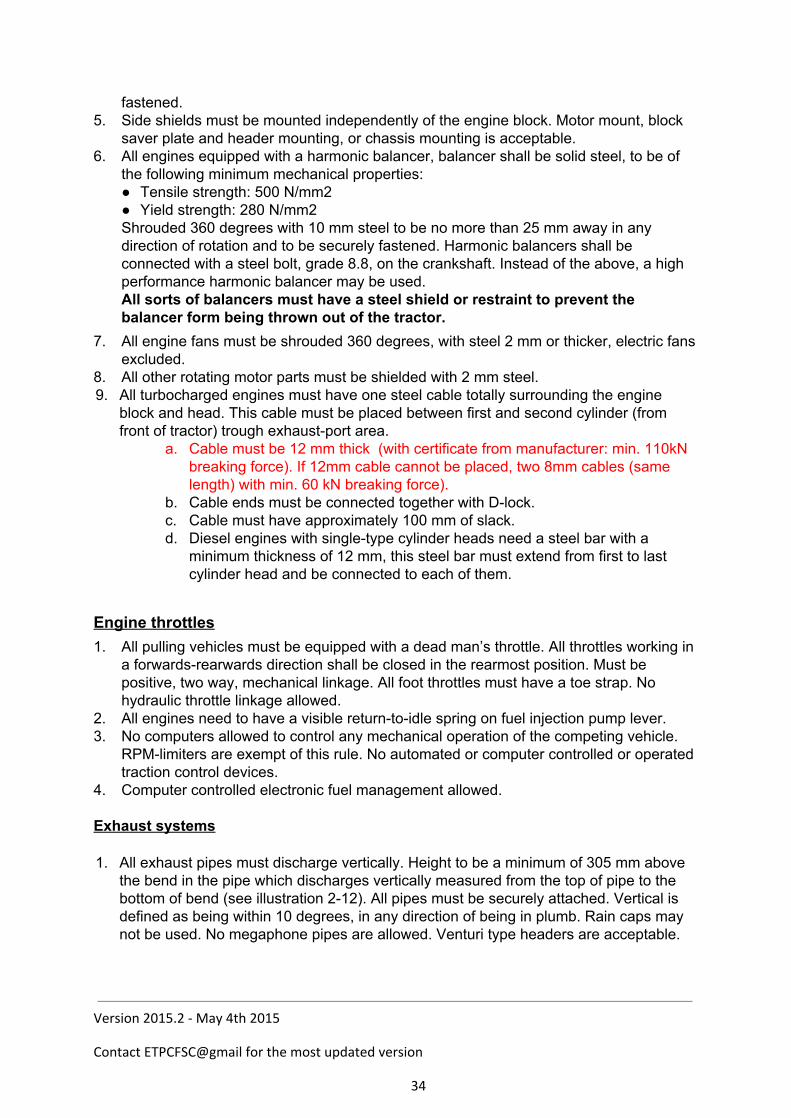
4. Computer controlled electronic fuel management allowed. Exhaust systems 1. All exhaust pipes must discharge vertically. Height to be a minimum of 305 mm above
the bend in the pipe which discharges vertically measured from the top of pipe to the bottom of bend (see illustration 212). All pipes must be securely attached. Vertical is defined as being within 10 degrees, in any direction of being in plumb. Rain caps may not be used. No megaphone pipes are allowed. Venturi type headers are acceptable.
Version 2015.2 - May 4th 2015
Contact ETPCFSC@gmail for the most updated version
34
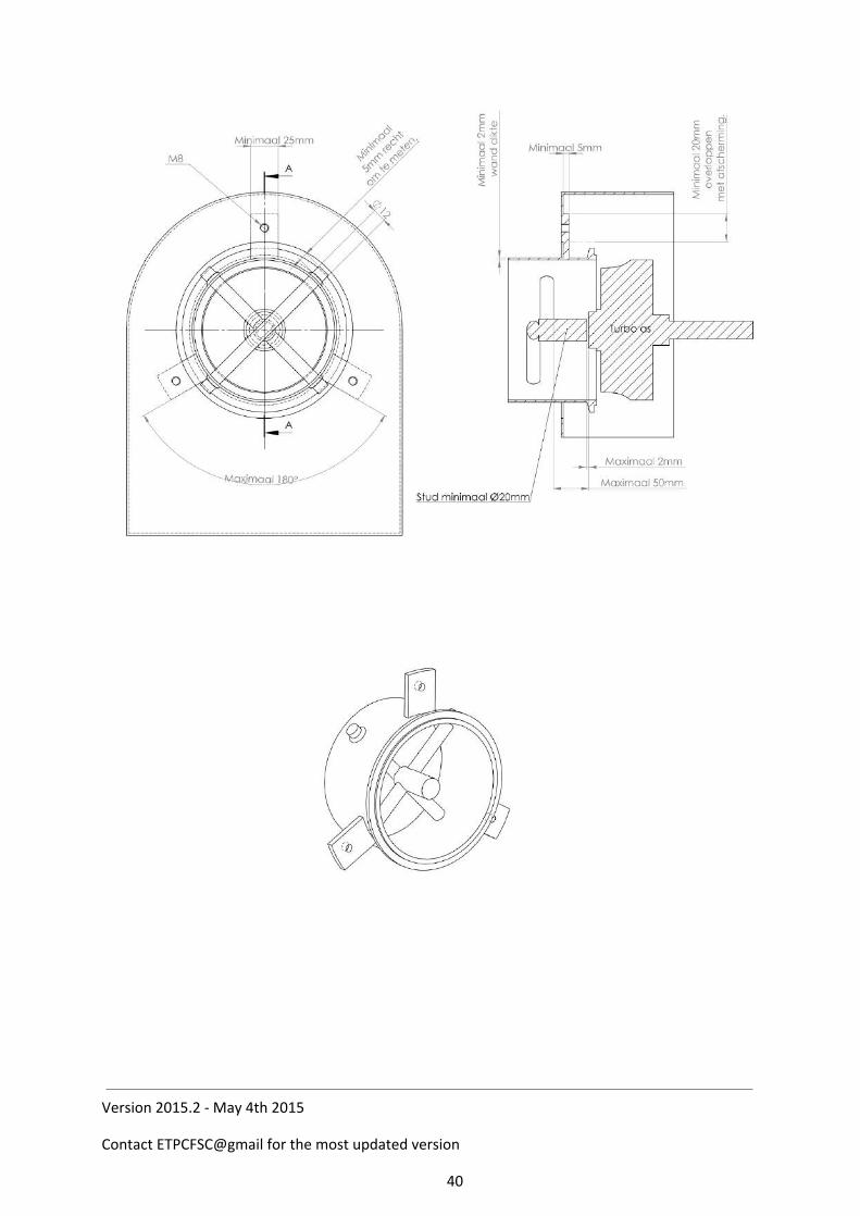
15. Turbo shielding: Turbocharger with exhaust outlet up to 95 mm. diameter All turbochargers must be completely shrouded (360 degrees), except for inlet and exhaust and supply pipes with 2mm steel. any openings in the guarding around inlet/exhaust/oil supply pipes can have a max. of 25 mm clearance to the guarding.(drawing 1) Front (inlet)and rear (exhaust) end of guarding must be closed with 2mm steel. The guarding must ensure that no wheels or other parts of the turbocharger can come out in case of a turbocharger explosion. The guarding must be mounted as close as possible to the turbocharger, at min. four (4) points with min. M8 8.8 bolts. (connection to inlet or exhaust pipe is not seen as connection point) Around every bolt hole must be min. 1.5 x hole diameter of material. Guarding must extend until cross in exhaust. Hood construction or grille cannot be part of the shielding. For tractors with a closed hood construction (min 2mm steel or min. 3mm aluminum), an open bottom to guarding with max. 90 degrees of the radial part is allowed. Open bottom shielding must extend at least 50 mm. below the bottom of the turbocharger. ( drawing 2). If turbo protection is made out of separate parts welds must be full length or 360 degrees round. In case of a bolted construction there must be min. M8 8.8 bolts used, placed at maximum of 75mm centres. Distance from bolt location to edge of the shielding or plate maximum 25 mm. Around every bolt hole must be minimum 1.5x hole diameter of material. Minimum overlap of material 32mm. ( drawing 3) Exhaust pipe must have a steel cross as close as possible to the turbo exhaust housing
Version 2015.2 - May 4th 2015
Contact ETPCFSC@gmail for the most updated version
35
outlet, but maximum 50 mm. from turbo exhaust wheel. Cross to be made from min.10 mm. diam. steel pin. (compact diesel:min. 8mm.diameter) Pins to be installed 90 degrees to each other , as closes as possible to each other. If exhaust pipe has a diameter larger than 95mm there must be a third pin of 10 mm maximum 50 mm from cross.(pin every 60 degrees) If exhaust pipe has a diameter larger than 160 mm there must be a fourth pin of 10 mm diam. max. 50 mm from cross. (pin every 45 degrees) Maximum diameter of exhaust pipe allowed is 200mm. Pins must have 5mm. visible on the outside of the exhaust pipe and be welded to the pipe. From cross to turbo exhaust wheel there must be an axial stud minimum 12mm diameter. Welded to the cross. Max. distance between axial stud and turbo exhaust wheel is 2mm. Wall thickness of exhaust pipe from turbo to cross min 4 mm. ( drawing 4) If it is not possible to use the 10mm pins , 25x5 mm. flat steel may be used as the cross. This cross must also follow the above rules concerning the stud and the 5mm visible on the outside plus the welding’s on the outside, and 3th. and 4th flat steel by bigger diameter pipe. Flat steel can only be used after written approval of the National and the ETPC T&S board. Exhaust pipe must have 3 additional connections to the exhaust protection to prevent pipe coming loose from turbo (if clamp fails or breaks) Connections made from min. 25x5 flat steel inside the turbocharger guarding. 25x5 flat steel to be connected with min. M8 8.8 bolts to guarding Around every bolt hole must be min. 1.5 x hole diameter material.(drawing 5) B. Turbocharger with exhaust outlet above 95 mm and up to 112 mm diameter As per rules for turbochargers with exhaust outlets up to 95 mm but with the following differences: Cross pins to be made from 12 mm diameter (not 10 mm) Axial stud to be made from 20 mm diameter (not 12 mm) C. Turbochargers with exhaust outlet above 112 mm and up to 132 mm diameter As per rules for turbochargers with exhaust outlet up to 95 mm but with the following differences: Cross pins to be made from 12 mm diameter (not 10 mm) Axial stud to be made from 20 mm diameter (not 10 mm) By one stage turbocharged diesel engines the following stronger shielding: All turbochargers must be completely shrouded (360 degrees), except for inlet, exhaust and oil supply pipes with 3mm steel. (radial part: pipe or rolled steel section)
Version 2015.2 - May 4th 2015
Contact ETPCFSC@gmail for the most updated version
36
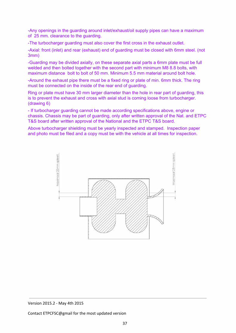
Any openings in the guarding around inlet/exhaust/oil supply pipes can have a maximum of 25 mm. clearance to the guarding. The turbocharger guarding must also cover the first cross in the exhaust outlet. Axial: front (inlet) and rear (exhaust) end of guarding must be closed with 6mm steel. (not 3mm) Guarding may be divided axially, on these separate axial parts a 6mm plate must be full welded and then bolted together with the second part with minimum M8 8.8 bolts, with maximum distance bolt to bolt of 50 mm. Minimum 5.5 mm material around bolt hole. Around the exhaust pipe there must be a fixed ring or plate of min. 6mm thick. The ring must be connected on the inside of the rear end of guarding. Ring or plate must have 30 mm larger diameter than the hole in rear part of guarding, this is to prevent the exhaust and cross with axial stud is coming loose from turbocharger. (drawing 6) If turbocharger guarding cannot be made according specifications above, engine or chassis. Chassis may be part of guarding, only after written approval of the Nat. and ETPC T&S board after written approval of the National and the ETPC T&S board. Above turbocharger shielding must be yearly inspected and stamped. Inspection paper and photo must be filed and a copy must be with the vehicle at all times for inspection.
Version 2015.2 - May 4th 2015
Contact ETPCFSC@gmail for the most updated version
37

Version 2015.2 - May 4th 2015
Contact ETPCFSC@gmail for the most updated version
38

Version 2015.2 - May 4th 2015
Contact ETPCFSC@gmail for the most updated version
39
Version 2015.2 - May 4th 2015
Contact ETPCFSC@gmail for the most updated version
40
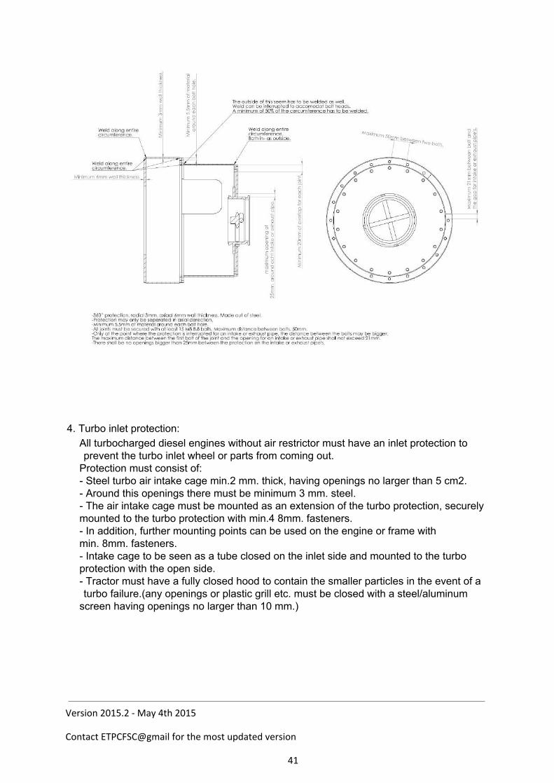
4. Turbo inlet protection:
All turbocharged diesel engines without air restrictor must have an inlet protection to prevent the turbo inlet wheel or parts from coming out. Protection must consist of: Steel turbo air intake cage min.2 mm. thick, having openings no larger than 5 cm2. Around this openings there must be minimum 3 mm. steel. The air intake cage must be mounted as an extension of the turbo protection, securely mounted to the turbo protection with min.4 8mm. fasteners. In addition, further mounting points can be used on the engine or frame with min. 8mm. fasteners. Intake cage to be seen as a tube closed on the inlet side and mounted to the turbo protection with the open side. Tractor must have a fully closed hood to contain the smaller particles in the event of a turbo failure.(any openings or plastic grill etc. must be closed with a steel/aluminum screen having openings no larger than 10 mm.)
Version 2015.2 - May 4th 2015
Contact ETPCFSC@gmail for the most updated version
41
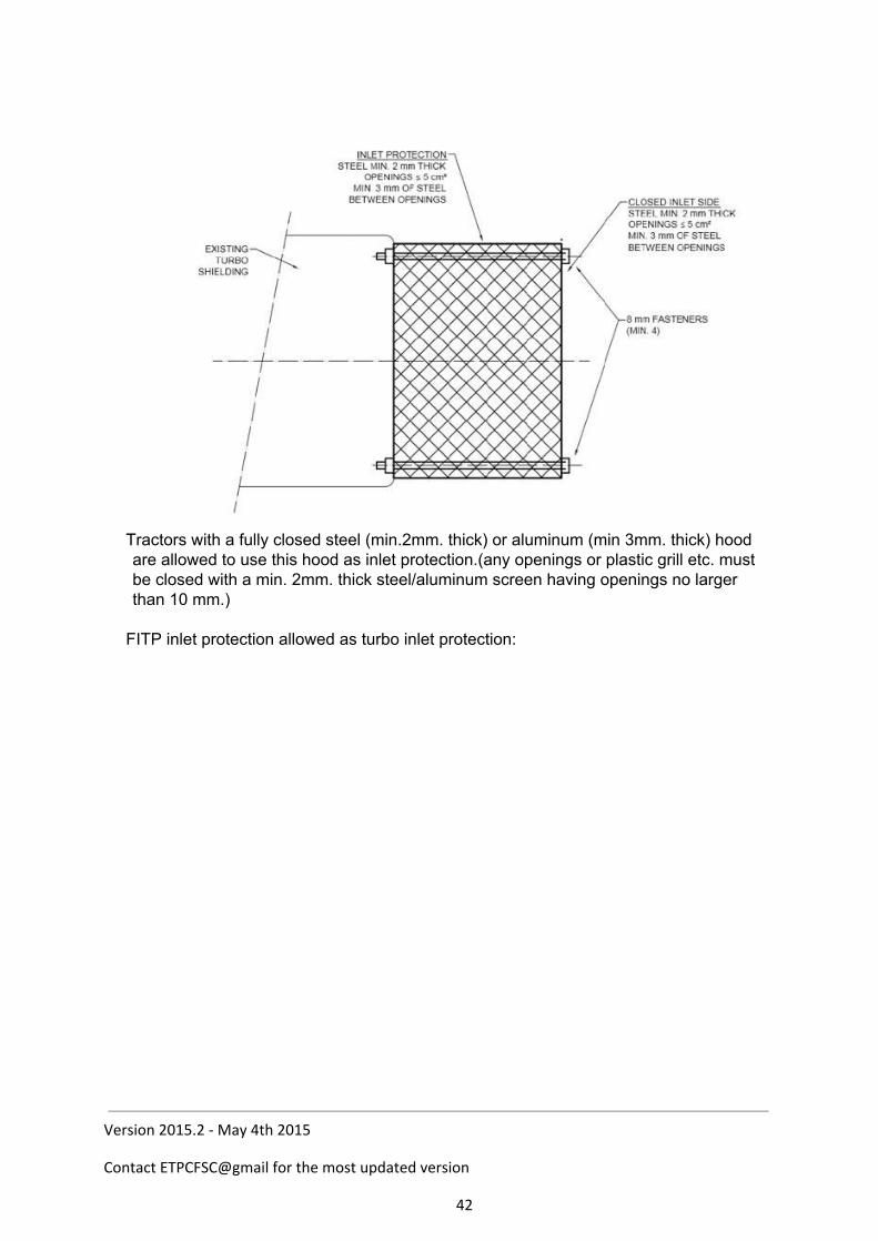
Tractors with a fully closed steel (min.2mm. thick) or aluminum (min 3mm. thick) hood are allowed to use this hood as inlet protection.(any openings or plastic grill etc. must be closed with a min. 2mm. thick steel/aluminum screen having openings no larger than 10 mm.) FITP inlet protection allowed as turbo inlet protection:
Version 2015.2 - May 4th 2015
Contact ETPCFSC@gmail for the most updated version
42
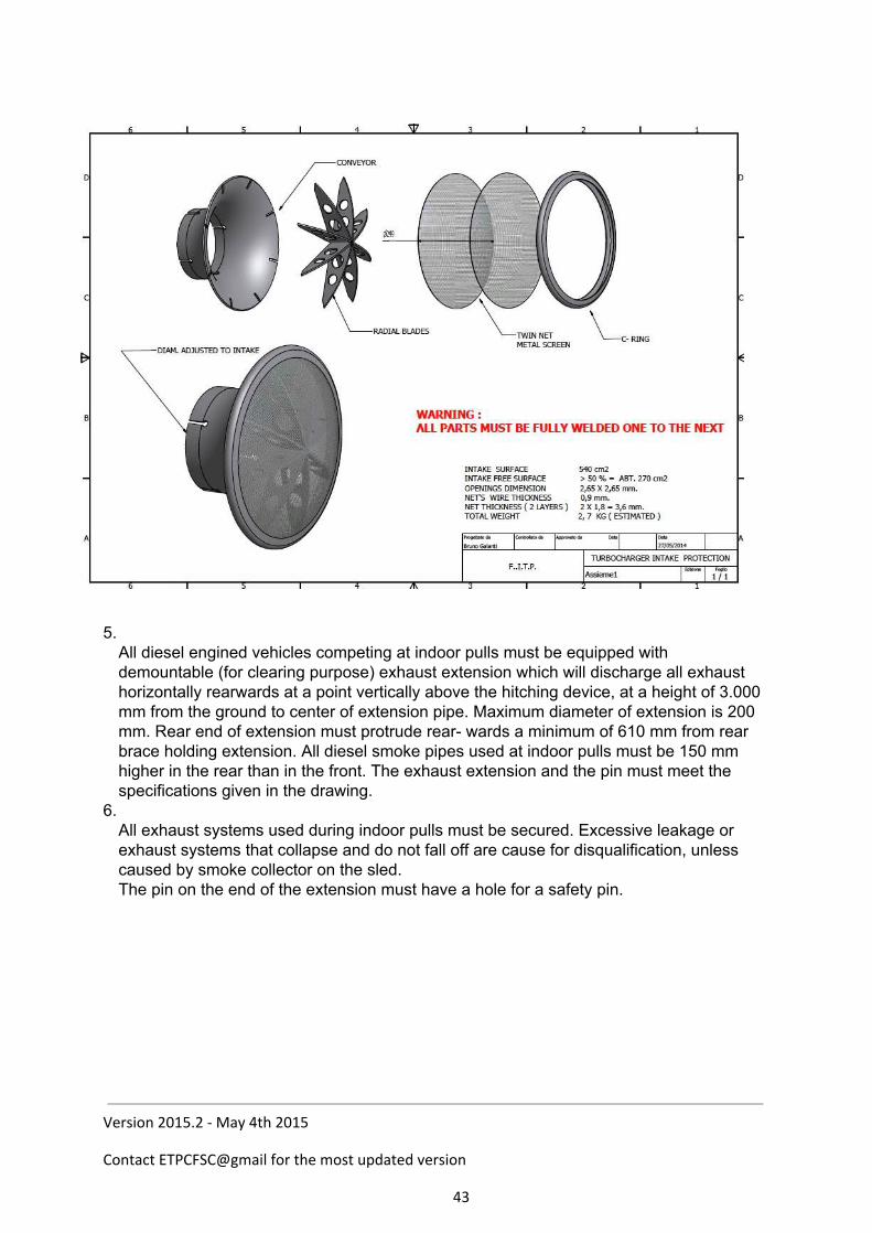
5. All diesel engined vehicles competing at indoor pulls must be equipped with demountable (for clearing purpose) exhaust extension which will discharge all exhaust horizontally rearwards at a point vertically above the hitching device, at a height of 3.000 mm from the ground to center of extension pipe. Maximum diameter of extension is 200 mm. Rear end of extension must protrude rear wards a minimum of 610 mm from rear brace holding extension. All diesel smoke pipes used at indoor pulls must be 150 mm higher in the rear than in the front. The exhaust extension and the pin must meet the specifications given in the drawing.
6. All exhaust systems used during indoor pulls must be secured. Excessive leakage or exhaust systems that collapse and do not fall off are cause for disqualification, unless caused by smoke collector on the sled. The pin on the end of the extension must have a hole for a safety pin.
Version 2015.2 - May 4th 2015
Contact ETPCFSC@gmail for the most updated version
43

Fuel and fuel containers
1. The only legal fuel is diesel. Oxygen carriers and combustion accelerators are illegal. Diesel fuel is defined by the ETPC as a pure hydrocarbon. The ETPC will evaluate diesel fuel using the dielectric constant value. That value shall be determined by the ETPCapproved fuel check meter only. The fuel check meter shall use cyclohexane to establish the zero reference point for determine all diesel fuel dielectric constant values. Diesel fuel to be used in ETPC sanctioned events shall have a dielectric value of no greater than 4.9, nor a value of no less than 2.0. The use of additives containing oxygen, such as nitro methane, propylene oxide, dioxide, MTBE, alcohol or nitrous oxide, are strictly prohibited. These additives, and others of the oxygenbearing family, will significantly change the dielectric constant value of any diesel fuel. Diesel fuel with dielectric constant values that fall outside the ETPCstandards will not be allowed for use in ETPC competition. It is prohibited other fluids, fuels or gas to add, inject or spray in or on any part of the tractor. The ETPC keeps the right to decide that the fuel that has to be used for the competition will be supplied thought the ETPC.
2. ETPC officials or officials form affiliated organizations can check fuel at any time during any event.
3. No fuel tanks, fuel pressure gauges, fuel pumps and/or fuel lines allowed in the driver’s compartment. If the fuel tank is located behind the driver, a fire barrier is highly recommended from front to rear of compartment beneath the driver’s seat between fuel line and driver. Minimum width of the fire barrier equal to width of driver’s seat.
Water Injection 1. Tractors equipped with an intercooler are permitted to use a water injection to cool the
inlet wheel with a single nozzle in front of the turbocharger only. Kill switches
1. All kill switches must be mounted independent of drawbar and or stabilizer bars. 2. All pulling vehicles must have an automatic ignition kill switch and / or air shutoff, in
Version 2015.2 - May 4th 2015
Contact ETPCFSC@gmail for the most updated version
44
working order at all times. The kill switch device must also work in a situation where the electric circuit of the vehicle is interrupted. Every kill switch must generally work according to the Fail Safe principle, that means no situation whatsoever may cause the kill switch go out of function. Track Officials and/or Tech Inspectors have the option of checking kill switches as many times as they feel adequate at any event. Switch must be checked with engine running or with Buzz Box only if supplied by puller.
3. The kill switch on all tractors must be located in the rear center of the vehicle (maximum of 150 mm off center in any direction) 1200 mm above the point of hook.
4. The kill switch must activate the air shutoff. A cable may be used for this purpose, but the flap must have a springloaded closing mechanism. A system to be deemed acceptable must at least prevent building of boost. A hole with a maximum diameter of 25 mm in the flap is allowed. It is recommended that a gasket/seal arrangement is used to shutoff the air flow more effectively. All diesel engines must be equipped with an emergency shutdown air shutoff at the air intake that can be utilized from the driver’s seat. On tractors with an electric kill switch system, the solenoids that hold the flap up must have positive (+) connection through the kill switch. Use of solenoids or electric motors that need voltage in order to activate the flap is not allowed. Also, systems that need air pressure to activate the kill which are not permitted.
5. The breakaway kill switches must have attached to them a minimum of 50 mm diameter ring. The cable from the sled will be attached to this ring. Kill switch ring or cable ‘ring’ must be secured with a nylon tie wrap (1/8 inch). The tie wrap must be broken for a repull. ETPC and affiliated organizations will supply the tie wraps for uniformity.
6. If a vehicle has a kill switch or shut off in legal position, and during the pull the kill switch is pulled and the nylon strap is broken and the presiding official inspects and finds the switch capable of operating properly under normal conditions, the vehicle will be allowed to repull immediately, or drop six positions. The decision to drop must be made before vehicle leaves the track. It is the puller responsibility to ensure that the kill switch is working.
7. The force which is necessary to pull the kill switch must be not more than 10 kilo. 8. All tractors must have a fuel shut off valve control within easy reach of driver (a fuel
shutoff valve on the diesel pump will do).Onboard batteries must be securely fastened and properly covered to prevent any sparks. Especially, any possibility of them getting into contact with the kill switch cable from the sled must be avoided.
Safety
1. If Track Officials and/or Tech Inspectors feels a vehicle is unsafe, they have the right not to allow the vehicle to pull.
2. All pulling vehicles must be equipped with a minimum of one 1.5 kg fire extinguisher (yearly checked with certificate) fully charged, in working condition, and within easy reach of the driver.
3. Governmentapproved fullface helmets are mandatory. All drivers in all classes must wear helmets with chin strap fastened when pulling.
4. The use of a fire suit (including gloves, socks, head socks, leather shoes) is mandatory for all drivers in all classes. Fire suits must meet the following requirements: A minimum of one layer fire suit of Nomex 3 or equivalent. Nomex or equivalent fabric underwear is highly recommended with the use of any
fire suit.
Version 2015.2 - May 4th 2015
Contact ETPCFSC@gmail for the most updated version
45
The maximum age of a Nomex fire suit is six (6) years, of other suits two (2) years, in cases of doubt it is the competitor’s duty to prove the age of the suit
Suits must have the possibility to tie collar, sleeves and legs. If leather boots are used fire socks are not mandatory.
5. Officials can ban any vehicle at any event from competition if they believe the vehicle has a potential safety problem.
6. The ETPC recommends the use of Tech Inspection stickers on all tractors, the best location is on the left front position of the tractor.
7. Drivers must be seated on the vehicle when his/her tractor is being started and running and must have complete control of the vehicle at all times Anytime an engine is being started or running, steering wheel must be installed an securely attached to steeringshaft.
8. A reverse safety light system is required on all pulling vehicles. A white light, minimum 50 mm in diameter, must be mounted directly above or below the safety kill switch at the rear of the vehicle. A white light, minimum 50 mm in diameter, in the drivers compartment must be operated by the same system. Both lights are to be activated by the gearshift lever in such way that it will be lit only when the vehicle is in reverse.
9. All pulling vehicles must have a neutral gear. They must be equipped with a starter interrupter switch on the gearshift, which will allow starter engagement only in neutral gearshift position.
10. The use of a safety belt with a fast draw latch for fast release is highly recommended in all classes without Roll Over Protection (ROP). In all classes with ROP the use of a 4point seatbeltassembly is mandatory. The seatbeltassembly must be attached to the roll cage.
11. Helpers must wear clothing with long sleeves on the track. 12. All tractors must have an rpm measuring point. This consists of a reflective sticker of
size 30mm x 30mm. It must be on an easily accessible point on the front of the engine. It must be possible to measure the RPM within three minutes; otherwise the competitor will be disqualified. Measuring will take place with a noncontact tachometer.
13. If the on board rpm measuring devices of the national associations is used, it is recommended to use two signals per revolution for good measurement. A single signal per revolution is not considered accurate enough to base decisions upon.
Firewall/deflection shield 1. Steel deflection shield between driver and engine from hood to top of torque tubes or
transmission or clutch housing from side shield to side shield, minimum 2 mm thick. This also serves as a flash fire shield.
Starting chemicals 1. All ether bottles (or starting aids) must be placed outside of engine compartment.
Onboard fire control systems 1. Supersport / farmstock tractors that require tools for removal of side shields must be
equipped with an onboard fire control system. Onboard system nozzles must be in engine compartment.
2. Supersport / farmstock tractors utilizing onboard fire extinguishing system must place one nozzle on each side of engine, inside the engine compartment. Not to be attached
Version 2015.2 - May 4th 2015
Contact ETPCFSC@gmail for the most updated version
46

to the sheetmetal.
Version 2015.2 - May 4th 2015
Contact ETPCFSC@gmail for the most updated version
47
Seats and fenders
1. All tractors must have a strong and rigid seat; all tip seats must be securely fastened while pulling. All seats must have side rails that are a minimum of 100 mm above the edges of the seat, must extend a minimum of onehalf the distance from the back of the seat to the front edge. If fenders are 150 mm or more above the seat, and are 150 mm or less from the seat, no seat side rails are required.
2. All tractors must have a shield between the driver and the tire, to consist of a solid barrier between driver and any part of the rear tires to be able to sufficiently support weight of driver.
RPM control
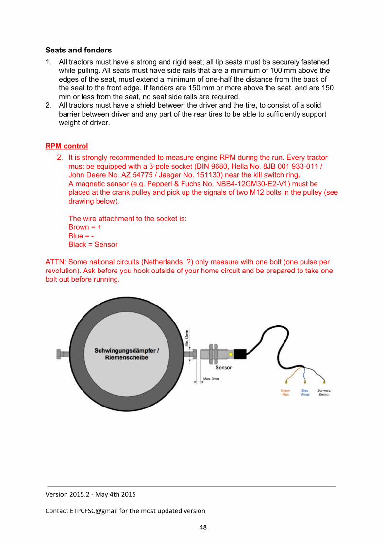
2. It is strongly recommended to measure engine RPM during the run. Every tractor must be equipped with a 3pole socket (DIN 9680, Hella No. 8JB 001 933011 / John Deere No. AZ 54775 / Jaeger No. 151130) near the kill switch ring. A magnetic sensor (e.g. Pepperl & Fuchs No. NBB412GM30E2V1) must be placed at the crank pulley and pick up the signals of two M12 bolts in the pulley (see drawing below). The wire attachment to the socket is: Brown = + Blue = Black = Sensor
ATTN: Some national circuits (Netherlands, ?) only measure with one bolt (one pulse per revolution). Ask before you hook outside of your home circuit and be prepared to take one bolt out before running.
Version 2015.2 - May 4th 2015
Contact ETPCFSC@gmail for the most updated version
48
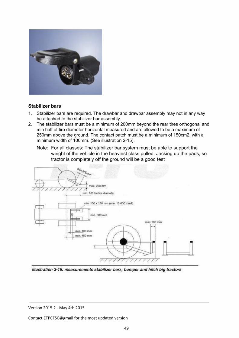
Stabilizer bars
1. Stabilizer bars are required. The drawbar and drawbar assembly may not in any way be attached to the stabilizer bar assembly.
2. The stabilizer bars must be a minimum of 200mm beyond the rear tires orthogonal and min half of tire diameter horizontal measured and are allowed to be a maximum of 250mm above the ground. The contact patch must be a minimum of 150cm2, with a minimum width of 100mm. (See illustration 215). Note: For all classes: The stabilizer bar system must be able to support the
weight of the vehicle in the heaviest class pulled. Jacking up the pads, so tractor is completely off the ground will be a good test
Version 2015.2 - May 4th 2015
Contact ETPCFSC@gmail for the most updated version
49
Roll Over protection
1. A roll over protection cage is mandatory in all classes. For details see: Appendix 5 or Chapter 14 of the ETPC rule book.
Turbocharger
1. All turbochargers must be completely shrouded (360 degrees) except for inlet and exhaust pipes with steel 2 mm or thicker. The shielding must ensure that no wheels or other parts of the turbo can come out in case of a turbo explosion. The shielding must be mounted as close as possible to the turbo, at min. four (4)
points Hood construction or grille cannot be part of the shielding. Open bottom (max. 90 degrees) of the shielding is allowed under the following
conditions: Must have a closed hood construction. Turbo shielding must extend at least 50 mm below the bottom of the turbo. Exhaustpipe thickness must be min. 1.5 mm from turbo to vertical part of
exhaustpipe and securely mounted to the turbocharger outlet flange. 2. All intercoolers located outside of normal the engine shielding must be shielded with
steel 2 mm thick or thicker. 3. On all pulling vehicles the tubing on the pressure side of a turbocharger to the intake
must be under the hood, shield or be bolted or strapped securely. 4. The ETPC recommends the use of a burst panel on charged engines. 5. Titanium turbowheels are not allowed in all classes.
Version 2015.2 - May 4th 2015
Contact ETPCFSC@gmail for the most updated version
50
Tires
1. Tractors are only allowed to drive with rubber tires; chains or similar are not allowed. All tires are allowed to be cut. Dual tires are not allowed.
2. The total width of the tractor is maximum 3000mm. This will be measured at the axle height.
3. The maximum allowed tire width is 30.5“ inch, or 800mm. The maximum diameter of wheel rims is 32” inch. If the width of the tires is less than or equal to 710mm, a wheel rim diameter of 42” inch is allowed. The manufacturer’s markings on the tires state the tire dimensions.
4. Puller tires are allowed. Weights
1. No weights may extend rearwards beyond rear tires. 2. All weights must be securely fastened. 3. Any ballast lost while hooked to the sled and under the green flag will be cause for
disqualification (internal breakage excepted). 4. The use of movable weights or movable weight carrier is not permitted. Legality 1. If the ETPC or national organization doubts the legality of any entry, or upon protest by
another contestant in that class, contestant in question must verify that 150 units of the tractor in question have been manufactured (notarized statement from the manufacturer), furnish parts numbers, and prove to the Board’s satisfaction that the tractor is legal.
4. Engine manufacturer must fit the hood. 5. The combination of engine, bellhousing/transmission and rearend must have been
manufactured in that combination (but not necessarily with that brand of hood).
Version 2015.2 - May 4th 2015
Contact ETPCFSC@gmail for the most updated version
51
Chapter 4 Level 4 Unlimited Farm Stock Class (Due to lack of interest, the class is under revision for 2016. It is supposed to go component and 4000kg at 7.347 cm3 (4valve) or 8.3l (2Valve) max. 3200 rpm)
Reason: Today’s tractor come with engines around 7l, 4 valve heads and huge transmissions. The engines would only be useful for the 3.5t/3.6t classes, but the rearends would never fit. Since we don’t want to promote machined cast housings with truck parts inside and actually have a “bridge” into Pro Stock, so you can start building a chassis if you found a suitable engine) Definition The Unlimited Farm Stock class is an RPM limited class, where modifications to increase the horsepower are allowed. Brakes
2. All competing vehicles must be equipped with working rear brakes. Towhitch
2. All vehicles are required to have a towhitch on the front of their vehicle. The towhitch can extend a maximum of 150 mm ahead of the furthermost front part of the vehicle (hitch will not be counted in total length when measuring the vehicle). The towhitch must have a 75 mm diameter hole, preferably positioned horizontally, and be strong enough for pushing or pulling the vehicle at its heaviest weight.
Drawbars
11. The pulling link to the sledge is from a draw bar with a 37mm thick hitch, with a round opening of minimum 75mm
12. Draw bars shall be constructed, so that in the event of a drawbar breakage the drawbar supports do not pull from a top link or brace above the centerline of the rear axle of the vehicle.
13. A drawbar which can be made shorter than legal length (from centre of rear axle: 45cm) is not acceptable.
14. Drawbars must be rigid in all directions. 15. Drawbars must be parallel to the ground with a tolerance +/ 10 degrees. The front axle
suspension must be totally lowered, if this is possible from the manufacturer. 16. Drawbars and hitching devices must be made out of solid steel with a minimum of 520
N/mm2 tensile strength in all weight classes. No welding on drawbars. 17. No part of the vehicle may interfere with sled, chain or hook, during a pull or while
being hooked or unhooked. 18. An area of 150 mm wide and 300 mm high, immediately above the draw bar, must be
free from all obstructions (including weights, stabilizer bars) for easy hooking and
Version 2015.2 - May 4th 2015
Contact ETPCFSC@gmail for the most updated version
52

unhooking. 19. Draw bar and stabilizer bars must not be connected to each other. 20. The drawbar distance from center of rear axle cannot change during pull. Note: The ETPC highly recommends that competing vehicle should not be tied up down to a tow vehicle through or on the drawbar in any way. Draw bars must meet the following: 4. A drawbar must be equipped with a hitching device, thickness 37 mm, and must have
a minimum 75 mm round hole. 5. Drawbars to be a minimum of 1900 mm2 total material (steel) at any point. This
includes the area of the mounting pin with the pin removed. 6. The mounting pin must be made of steel with a thickness of 25 mm. 7. The vertical cross section AA of the drawbar must be a minimum of 1900 mm2, and
the horizontal cross section GG must be a minimum of 1000 mm2 with a minimum of 10 mm of cross sectional thickness between the front of drawbar and the pinhole (H).
Clutches, flywheels, automatics and protection
Version 2015.2 - May 4th 2015
Contact ETPCFSC@gmail for the most updated version
53

3. Only mechanically activated clutches are permitted. Hydraulic engagement is allowed. 4. Clutches, flywheels and protection must meet the ETPC specifications for Pro Stocks
(see ETPC rulebook or appendix 3). Shatter blankets 3. Shatter blankets must be on the inside of the tie bars or one piece frame and the tie
bars must be fastened forward of the rear of the engine block. However, in some occasions there is no space for the blanket inside the tie bar or the one piece frame, in that case a written approval from ETPC or affiliated organization must be available to Tech Inspectors.
Chassis It shall consist of the following: 15. The stock engine block or OEM engine block that will operate with the stock crankshaft
for that model without any alterations for chassis mounting. 16. Engine block must remain in original location as located by manufacturer. 17. All engines must be secured and held rigid to OEM chassis. Engine cannot move
independent or rear end/transmission housing. 18. The stock transmission housing or manufacturer’s replacement and the stock final
drive housing or manufacturer’s replacement. Planetaries are considered part of final drive and are not removable.
19. The OEM engine block cannot be modified externally, except for normal repair or for mounting of fuel injection equipment.
20. Internal webbing and water jacket must remain intact with provisions to rebore engine block.
21. Any alterations to the chassis shell must have the written approval of the ETPC and the national Tech and Safety Board (TSB), before the tractor in question will be considered legal.
22. The chassis and frame must remain stock from the rear of the engine block to the rear of the tractor.
23. The only vehicles that are considered legal in unlimited Farm Stock classes are those that are available as farm tractors with front wheel steering.
24. The clutch housing, transmission case, rear end housing and axle housing must be OEM, with no aluminum replacements.
25. The use of a spacer between engine block is allowed with a maximum additional thickness of 35 mm. An aluminum spacerplate cannot be part of the clutch protection.
26. There must not be a visible part in the drive line that is of another brand. 27. The drive line, made up of motor, bell housing, gearbox and rear axle, must hold
without external strengthening. Connecting plates, flanges or weldedon parts are not allowed, except if engine and bell housing do not form one unit in the original tractor. In that case the tractor must have a self carrying frame (refer to point Frame/sheetmetal below).
28. Advertising boards are allowed, providing they do not influence the visibility of the driver. They may not extent over the sides.
Version 2015.2 - May 4th 2015
Contact ETPCFSC@gmail for the most updated version
54
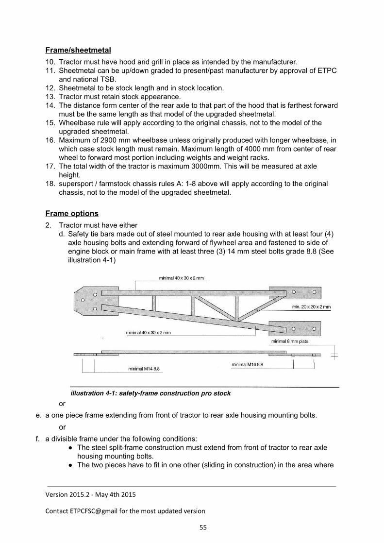
Frame/sheetmetal 10. Tractor must have hood and grill in place as intended by the manufacturer. 11. Sheetmetal can be up/down graded to present/past manufacturer by approval of ETPC
and national TSB. 12. Sheetmetal to be stock length and in stock location. 13. Tractor must retain stock appearance. 14. The distance form center of the rear axle to that part of the hood that is farthest forward
must be the same length as that model of the upgraded sheetmetal. 15. Wheelbase rule will apply according to the original chassis, not to the model of the
upgraded sheetmetal. 16. Maximum of 2900 mm wheelbase unless originally produced with longer wheelbase, in
which case stock length must remain. Maximum length of 4000 mm from center of rear wheel to forward most portion including weights and weight racks.
17. The total width of the tractor is maximum 3000mm. This will be measured at axle height.
18. supersport / farmstock chassis rules A: 18 above will apply according to the original chassis, not to the model of the upgraded sheetmetal.
Frame options 2. Tractor must have either
d. Safety tie bars made out of steel mounted to rear axle housing with at least four (4) axle housing bolts and extending forward of flywheel area and fastened to side of engine block or main frame with at least three (3) 14 mm steel bolts grade 8.8 (See illustration 41)
or e. a one piece frame extending from front of tractor to rear axle housing mounting bolts.
or f. a divisible frame under the following conditions:
The steel splitframe construction must extend from front of tractor to rear axle housing mounting bolts.
The two pieces have to fit in one other (sliding in construction) in the area where
Version 2015.2 - May 4th 2015
Contact ETPCFSC@gmail for the most updated version
55
the tractor can be split (clutch area). The two pieces of the frame must be made of tubes or ushaped steel with a
thickness of at least 3 mm. If the frame is made of ushaped steel It must have a ushaped connection bar
inside min. 500 mm length. (250 mm in the rear part and 250 mm in the front part of the ushaped split frame).
If the frame is made out of tubes it must have inner tubes min. 500 mm length. (250 mm in the rear part and 250 mm in the front part of the tubeframe).
Rear part of the frame hast to be mounted to rearaxle housing with at least four (4) axlehousing bolts and extending forward of flywheel area and fastened to side of engine block or motorplate with at least three (3) 14 mm bolts min. grade 8.8.
Two parts of frame must be locked together with at least two (2) fasteners of 8 mm steel.
Two piece frame must be of sufficient strength to support weight of tractor with the bolts used to split the tractor removed.
4. Tie bars or frame must be of sufficient strength to support weight of tractor with the bolts used to split the tractor removed.
Limits 3. 4,5 ton:
a. engine size max. 7.347 cm3, with turbo charger, rpm: max. 3200. b. Maximum four valves per cylinder allowed.
Engines
16. The mounting of maximum one (1) turbocharger, consisting of inlet and exhaust, is allowed. No mechanical blowers / superchargers.
17. Engine head must be OEM agricultural type for that brand engine. It is allowed to change the cylinder head, providing the change was made on the original motor block in production. Length, width and height must remain the original measurements. It must also be possible to fit the inlet and exhaust manifolds in the same position as the original. It is not allowed to add extra inlet and outlets.
18. Unlimited Farm Stock tractors may have one (1) fuel injection pump of any size, only one (1) pump element per cylinder allowed. If using OEM (Available on partscounter) 12 cylinder fuelinjectionpump two (2) pump elements per cylinder allowed.
19. Diesel fuel only. Water injection is not allowed. Inter cooler allowed. Use of gasohol and/or alcohol is prohibited.
20. No overhead camshafts allowed. 21. Conversion from 4stroke into 2 stroke principle is not allowed. 22. Downsizing the engine by 2% is allowed. 23. The use of a deck plate between the bottom of the cylinder head and the top of the
engine block is only allowed if the engine is not downsized. The maximum distance between the centerline of the crankshaft and the top of the engine block, including deck plate and gasket material is 410mm.
24. One piece engine main cap bearings allowed. One piece main cap not considered a girdle.
25. Injection pump and camshaft have to be driven the original way. Different flanges,
Version 2015.2 - May 4th 2015
Contact ETPCFSC@gmail for the most updated version
56
extensions or turning the injection pump around are allowed. 26. The use of another sump is allowed, providing it is not part of the carrying structure
in frameless tractors. It must be possible to replace the original sump on the motor block in its original position.
27. A girdle under the motor block is allowed, and falls under the same rules as the sump.
28. The use of another rocker cover is allowed. It must be possible to replace the original rocker cover on the cylinder head in its original position.
29. The competitor needs to drill two holes of (3.5 mm) into two bolts (next to each other) of the sump. These holes can be used to seal the engine.
Engine shielding
10. A deflection shield is required on both sides of all engines. Shield must extend the complete length of block casting and be securely fastened. Is to be made of aluminum or steel, minimum thickness 2 mm. Shields must be solid. Motor mounts, filters, steering rods, etc. cannot serve as part of shield. Solid frame rails with no holes can serve as part or all of shield, providing it covers required areas of block casting. It is recommended that a quick release fastener be used (winged Dzus typ or cotter pin type hoop pins). Use of bolts with nuts, screw locks are discouraged. (reason: ease of access in case of emergencyfire, run off, etc.
11. Shielding on all tractors with in line engines must be from sheet metal (hood) to 50 mm below bottom center of crankshaft throw, and be securely fastened. They may be louvered, but no expanded metal. Fastening of hood and side shielding must be strong enough to keep them in place in case of an explosion.
12. Starter motors, fuel filters, oil filters and fuel injection pumps may not be used as shielding. Shielding ma cover or pass behind starter or fuel pump.
13. Shielding on all V or Y type engines must extend from base of head or the uppermost point of piston, travel to 50 mm below bottom of crankshaft throw, and be securely fastened.
14. Side shields must be mounted independently of the engine block. Motor mount, block saver plate and header mounting, or chassis mounting is acceptable.
15. All engines equipped with a harmonic balancer, balancer shall be solid steel, to be of the following minimum mechanical properties: Tensile strength: 500 N/mm2 Yield strength: 280 N/mm2 Shrouded 360 degrees with 10 mm steel to be no more than 25 mm away in any direction of rotation and to be securely fastened. Harmonic balancers shall be connected with a steel bolt, grade 8.8, on the crankshaft. Instead of the above, a high performance harmonic balancer may be used. All sorts of balancers must have a steel shield or restraint to prevent the balancer form being thrown out of the tractor.
16. All engine fans must be shrouded 360 degrees, with steel 2 mm or thicker, electric fans excluded.
17. All other rotating motor parts must be shielded with 2 mm steel. 18. All turbocharged engines must have one steel cable totally surrounding the engine
block and head. This cable must be placed between first and second cylinder (from front of tractor) trough exhaustport area.
Version 2015.2 - May 4th 2015
Contact ETPCFSC@gmail for the most updated version
57
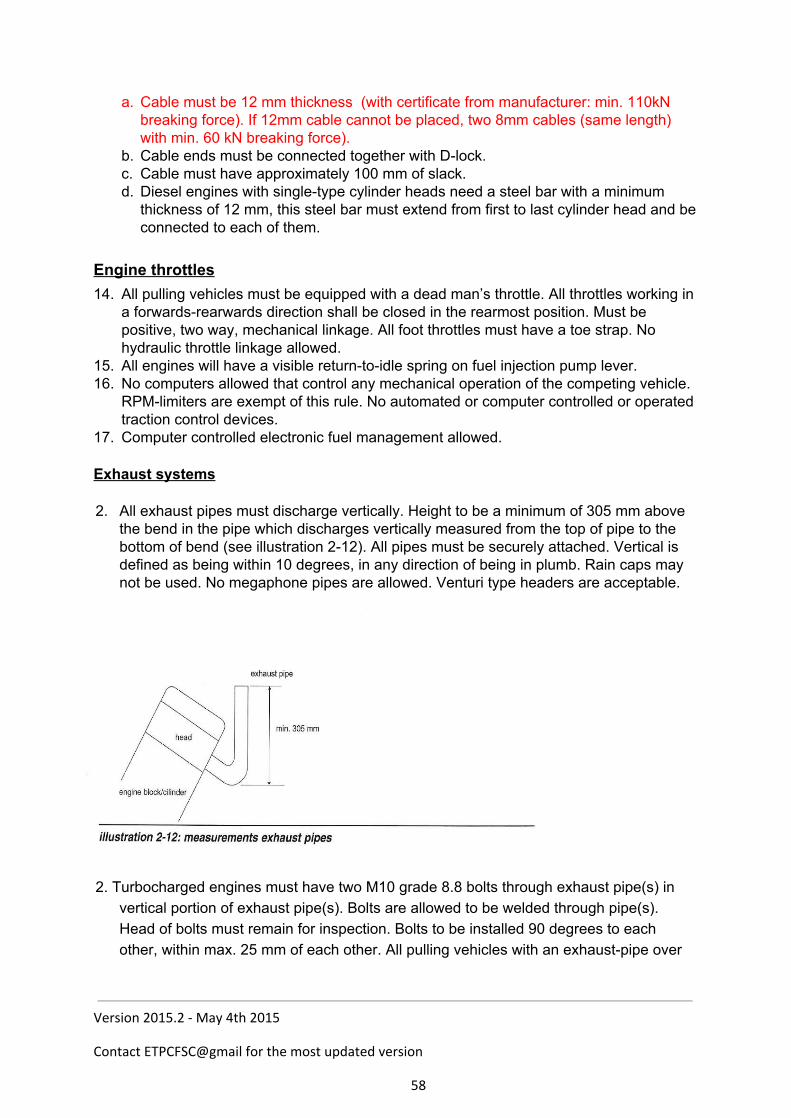
a. Cable must be 12 mm thickness (with certificate from manufacturer: min. 110kN breaking force). If 12mm cable cannot be placed, two 8mm cables (same length) with min. 60 kN breaking force).
b. Cable ends must be connected together with Dlock. c. Cable must have approximately 100 mm of slack. d. Diesel engines with singletype cylinder heads need a steel bar with a minimum
thickness of 12 mm, this steel bar must extend from first to last cylinder head and be connected to each of them.
Engine throttles
14. All pulling vehicles must be equipped with a dead man’s throttle. All throttles working in a forwardsrearwards direction shall be closed in the rearmost position. Must be positive, two way, mechanical linkage. All foot throttles must have a toe strap. No hydraulic throttle linkage allowed.
15. All engines will have a visible returntoidle spring on fuel injection pump lever. 16. No computers allowed that control any mechanical operation of the competing vehicle.
RPMlimiters are exempt of this rule. No automated or computer controlled or operated traction control devices.
17. Computer controlled electronic fuel management allowed. Exhaust systems 2. All exhaust pipes must discharge vertically. Height to be a minimum of 305 mm above
the bend in the pipe which discharges vertically measured from the top of pipe to the bottom of bend (see illustration 212). All pipes must be securely attached. Vertical is defined as being within 10 degrees, in any direction of being in plumb. Rain caps may not be used. No megaphone pipes are allowed. Venturi type headers are acceptable.
2. Turbocharged engines must have two M10 grade 8.8 bolts through exhaust pipe(s) in
vertical portion of exhaust pipe(s). Bolts are allowed to be welded through pipe(s). Head of bolts must remain for inspection. Bolts to be installed 90 degrees to each other, within max. 25 mm of each other. All pulling vehicles with an exhaustpipe over
Version 2015.2 - May 4th 2015
Contact ETPCFSC@gmail for the most updated version
58
95 mm diameter must have extra cross in exhaustpipe, rotated 45 degrees from the first cross. Both crosses closest possible to each other.
3. Turbocharged diesel engines must have an additional cross as close as possible to the
turbo. Cross must be made from 2 M12 bolts 8.8 or better. Bolts to be installed 90 degrees to each other, within max. 20 mm. of each other. In case the cross must be placed farther away from the turbo, wallthickness of exhaustpipe between turbo and cross must be min. 4mm.
4. Turbo inlet protection:
All turbocharged diesel engines without air restrictor must have an inlet protection to prevent the turbo inlet wheel or parts from coming out. Protection must consist of: Steel turbo air intake cage min.2 mm. thick, having openings no larger than 5 cm2. Around this openings there must be minimum 3 mm. steel. The air intake cage must be mounted as an extension of the turbo protection, securely mounted to the turbo protection with min.4 8mm. fasteners. In addition, further mounting points can be used on the engine or frame with min. 8mm. fasteners. Intake cage to be seen as a tube closed on the inlet side and mounted to the turbo protection with the open side. Tractor must have a fully closed hood to contain the smaller particles in the event of a turbo failure.(any openings or plastic grill etc. must be closed with a steel/aluminum screen having openings no larger than 10 mm.) Tractors with a fully closed steel (min.2mm. thick) or aluminum (min 3mm. thick) hood are allowed to use this hood as inlet protection.(any openings or plastic grill etc. must be closed with a min. 2mm. thick steel/aluminum screen having openings no larger than 10 mm.)
Version 2015.2 - May 4th 2015
Contact ETPCFSC@gmail for the most updated version
59
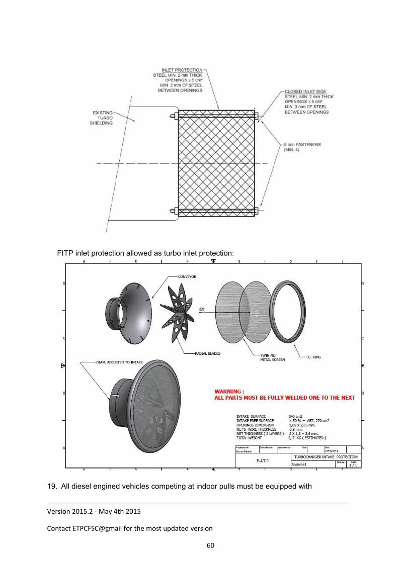
FITP inlet protection allowed as turbo inlet protection:
19. All diesel engined vehicles competing at indoor pulls must be equipped with
Version 2015.2 - May 4th 2015
Contact ETPCFSC@gmail for the most updated version
60
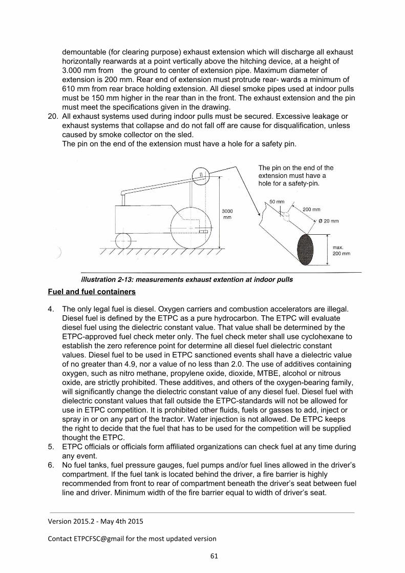
demountable (for clearing purpose) exhaust extension which will discharge all exhaust horizontally rearwards at a point vertically above the hitching device, at a height of 3.000 mm from the ground to center of extension pipe. Maximum diameter of extension is 200 mm. Rear end of extension must protrude rear wards a minimum of 610 mm from rear brace holding extension. All diesel smoke pipes used at indoor pulls must be 150 mm higher in the rear than in the front. The exhaust extension and the pin must meet the specifications given in the drawing.
20. All exhaust systems used during indoor pulls must be secured. Excessive leakage or exhaust systems that collapse and do not fall off are cause for disqualification, unless caused by smoke collector on the sled. The pin on the end of the extension must have a hole for a safety pin.
Fuel and fuel containers
4. The only legal fuel is diesel. Oxygen carriers and combustion accelerators are illegal. Diesel fuel is defined by the ETPC as a pure hydrocarbon. The ETPC will evaluate diesel fuel using the dielectric constant value. That value shall be determined by the ETPCapproved fuel check meter only. The fuel check meter shall use cyclohexane to establish the zero reference point for determine all diesel fuel dielectric constant values. Diesel fuel to be used in ETPC sanctioned events shall have a dielectric value of no greater than 4.9, nor a value of no less than 2.0. The use of additives containing oxygen, such as nitro methane, propylene oxide, dioxide, MTBE, alcohol or nitrous oxide, are strictly prohibited. These additives, and others of the oxygenbearing family, will significantly change the dielectric constant value of any diesel fuel. Diesel fuel with dielectric constant values that fall outside the ETPCstandards will not be allowed for use in ETPC competition. It is prohibited other fluids, fuels or gasses to add, inject or spray in or on any part of the tractor. Water injection is not allowed. De ETPC keeps the right to decide that the fuel that has to be used for the competition will be supplied thought the ETPC.
5. ETPC officials or officials form affiliated organizations can check fuel at any time during any event.
6. No fuel tanks, fuel pressure gauges, fuel pumps and/or fuel lines allowed in the driver’s compartment. If the fuel tank is located behind the driver, a fire barrier is highly recommended from front to rear of compartment beneath the driver’s seat between fuel line and driver. Minimum width of the fire barrier equal to width of driver’s seat.
Version 2015.2 - May 4th 2015
Contact ETPCFSC@gmail for the most updated version
61
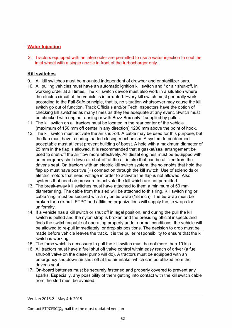
Water Injection 2. Tractors equipped with an intercooler are permitted to use a water injection to cool the
inlet wheel with a single nozzle in front of the turbocharger only. Kill switches
9. All kill switches must be mounted independent of drawbar and or stabilizer bars. 10. All pulling vehicles must have an automatic ignition kill switch and / or air shutoff, in
working order at all times. The kill switch device must also work in a situation where the electric circuit of the vehicle is interrupted. Every kill switch must generally work according to the Fail Safe principle, that is, no situation whatsoever may cause the kill switch go out of function. Track Officials and/or Tech Inspectors have the option of checking kill switches as many times as they fee adequate at any event. Switch must be checked with engine running or with Buzz Box only if supplied by puller.
11. The kill switch on all tractors must be located in the rear center of the vehicle (maximum of 150 mm off center in any direction) 1200 mm above the point of hook.
12. The kill switch must activate the air shutoff. A cable may be used for this purpose, but the flap must have a springloaded closing mechanism. A system to be deemed acceptable must at least prevent building of boost. A hole with a maximum diameter of 25 mm in the flap is allowed. It is recommended that a gasket/seal arrangement be used to shutoff the air flow more effectively. All diesel engines must be equipped with an emergency shutdown air shutoff at the air intake that can be utilized from the driver’s seat. On tractors with an electric kill switch system, the solenoids that hold the flap up must have positive (+) connection through the kill switch. Use of solenoids or electric motors that need voltage in order to activate the flap is not allowed. Also, systems that need air pressure to activate the kill which are not permitted.
13. The breakaway kill switches must have attached to them a minimum of 50 mm diameter ring. The cable from the sled will be attached to this ring. Kill switch ring or cable ‘ring’ must be secured with a nylon tie wrap (1/8 inch). The tie wrap must be broken for a repull. ETPC and affiliated organizations will supply the tie wraps for uniformity.
14. If a vehicle has a kill switch or shut off in legal position, and during the pull the kill switch is pulled and the nylon strap is broken and the presiding official inspects and finds the switch capable of operating properly under normal conditions, the vehicle will be allowed to repull immediately, or drop six positions. The decision to drop must be made before vehicle leaves the track. It is the puller responsibility to ensure that the kill switch is working.
15. The force which is necessary to pull the kill switch must be not more than 10 kilo. 16. All tractors must have a fuel shut off valve control within easy reach of driver (a fuel
shutoff valve on the diesel pump will do). A tractors must be equipped with an emergency shutdown air shutoff at the airintake, which can be utilized from the driver’s seat.
17. Onboard batteries must be securely fastened and properly covered to prevent any sparks. Especially, any possibility of them getting into contact with the kill switch cable from the sled must be avoided.
Version 2015.2 - May 4th 2015
Contact ETPCFSC@gmail for the most updated version
62

Version 2015.2 - May 4th 2015
Contact ETPCFSC@gmail for the most updated version
63

Safety
1. If Track Officials and/or Tech Inspectors feels a vehicle is unsafe, they have the right not to allow the vehicle to pull.
2. All pulling vehicles must be equipped with a minimum of one 1.5 kg fire extinguisher (yearly checked with certificate) fully charged, in working condition, and within easy reach of the driver.
3. Governmentapproved fullface helmets are mandatory. All drivers in all classes must wear helmets with chin strap fastened when pulling.
4. The use of a fire suit (including gloves, socks, head socks, leather shoes) is mandatory for all drivers in all classes. Fire suits must meet the following requirements: A minimum of one layer fire suit of Nomex 3 or equivalent. Nomex or equivalent fabric underwear is highly recommended with the use of any
fire suit. The maximum age of a Nomex fire suit is six (6) years, of other suits two (2) years,
in cases of doubt it is the competitor’s duty to prove the age of the suit Suits must have the possibility to tie collar, sleeves and legs. If leather boots are
used fire socks are not mandatory. 18. Officials can ban any vehicle at any event from competition if they believe the vehicle
has a potential safety problem. 19. The ETPC recommends the use of Tech Inspection stickers on all tractors, the best
location is on the left front position of the tractor. 20. Drivers must be seated on the vehicle when his/her tractor is being started and running
and must have complete control of the vehicle at all times Anytime an engine is being started or running, steering wheel must be installed an securely attached to steeringshaft.
21. A reverse safety light system is required on all pulling vehicles. A white light, minimum 50 mm in diameter, must be mounted directly above or below the safety kill switch at the rear of the vehicle. A white light, minimum 50 mm in diameter, in the drivers compartment must be operated by the same system. Both lights are to be activated by the gearshift lever in such way that it will be lit only when the vehicle is in reverse.
22. All pulling vehicles must have a neutral gear. They must be equipped with a starter interrupter switch on the gearshift, which will allow starter engagement only in neutral gearshift position.
23. The use of a safety belt with a fast draw latch for fast release is highly recommended in all classes without Roll Over Protection (ROP). In all classes with ROP the use of a 4point seatbeltassembly is mandatory. The seatbeltassembly must be attached to the roll cage.
24. Helpers must wear clothing with long sleeves on the track. 25. All tractors must have an rpm measuring point. This consists of a reflective sticker of
size 30mm x 30mm. It must be on an easily accessible point on the front of the engine. It must be possible to measure the RPM within three minutes; otherwise the competitor will be disqualified. Measuring will take place with a noncontact tachometer.
26. If the on board rpm measuring devices of the national associations is used, it is recommended to use two signals per revolution for good measurement. A single signal per revolution is not considered accurate enough to base decisions upon.
Firewall/deflection shield 2. Steel deflection shield between driver and engine from hood to top of torque tubes or
Version 2015.2 - May 4th 2015
Contact ETPCFSC@gmail for the most updated version
64
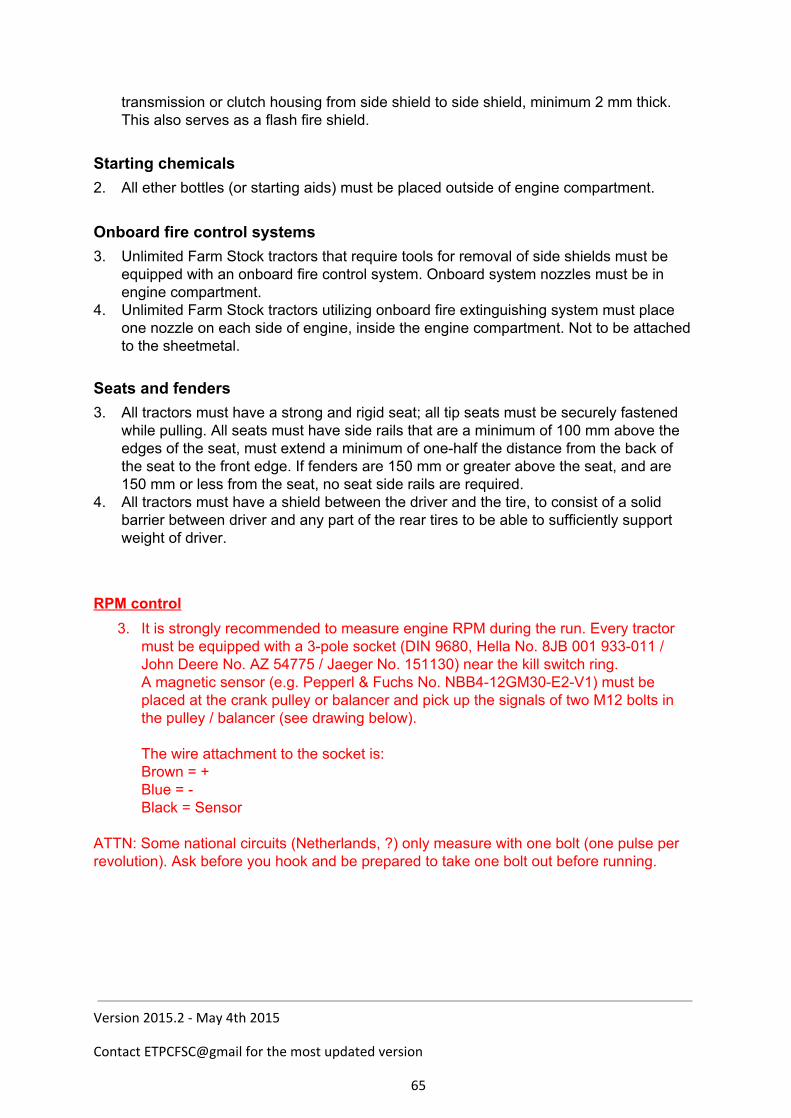
transmission or clutch housing from side shield to side shield, minimum 2 mm thick. This also serves as a flash fire shield.
Starting chemicals 2. All ether bottles (or starting aids) must be placed outside of engine compartment.
Onboard fire control systems 3. Unlimited Farm Stock tractors that require tools for removal of side shields must be
equipped with an onboard fire control system. Onboard system nozzles must be in engine compartment.
4. Unlimited Farm Stock tractors utilizing onboard fire extinguishing system must place one nozzle on each side of engine, inside the engine compartment. Not to be attached to the sheetmetal.
Seats and fenders
3. All tractors must have a strong and rigid seat; all tip seats must be securely fastened while pulling. All seats must have side rails that are a minimum of 100 mm above the edges of the seat, must extend a minimum of onehalf the distance from the back of the seat to the front edge. If fenders are 150 mm or greater above the seat, and are 150 mm or less from the seat, no seat side rails are required.
4. All tractors must have a shield between the driver and the tire, to consist of a solid barrier between driver and any part of the rear tires to be able to sufficiently support weight of driver.
RPM control
3. It is strongly recommended to measure engine RPM during the run. Every tractor must be equipped with a 3pole socket (DIN 9680, Hella No. 8JB 001 933011 / John Deere No. AZ 54775 / Jaeger No. 151130) near the kill switch ring. A magnetic sensor (e.g. Pepperl & Fuchs No. NBB412GM30E2V1) must be placed at the crank pulley or balancer and pick up the signals of two M12 bolts in the pulley / balancer (see drawing below). The wire attachment to the socket is: Brown = + Blue = Black = Sensor
ATTN: Some national circuits (Netherlands, ?) only measure with one bolt (one pulse per revolution). Ask before you hook and be prepared to take one bolt out before running.
Version 2015.2 - May 4th 2015
Contact ETPCFSC@gmail for the most updated version
65
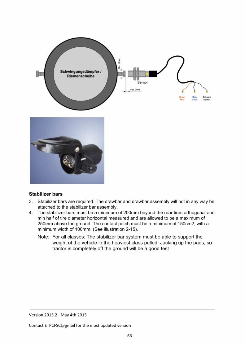
Stabilizer bars
3. Stabilizer bars are required. The drawbar and drawbar assembly will not in any way be attached to the stabilizer bar assembly.
4. The stabilizer bars must be a minimum of 200mm beyond the rear tires orthogonal and min half of tire diameter horizontal measured and are allowed to be a maximum of 250mm above the ground. The contact patch must be a minimum of 150cm2, with a minimum width of 100mm. (See illustration 215). Note: For all classes: The stabilizer bar system must be able to support the
weight of the vehicle in the heaviest class pulled. Jacking up the pads, so tractor is completely off the ground will be a good test
Version 2015.2 - May 4th 2015
Contact ETPCFSC@gmail for the most updated version
66

Roll Over protection
2. A roll over protection cage is mandatory in all classes. For details see: Appendix 5 or Chapter 14 of the ETPC rule book.
Turbocharger
6. All turbochargers must be completely shrouded (360 degrees)m except for inlet and exhaust pipes with steel 2 mm or thicker. The shielding must ensure that no wheels or other parts of the turbo can come out in case of a turbo explosion. The shielding must be mounted as close as possible to the turbo, at min. four (4)
points Hood construction or grille cannot be part of the shielding. Open bottom (max. 90 degrees) of the shielding is allowed under the following
conditions: Must have a closed hood construction. Turbo shielding must extend at least 50 mm below the bottom of the turbo. Exhaustpipe thickness must be min. 1.5 mm from turbo to vertical part of
exhaustpipe and securely mounted to the turbocharger outlet flange. 7. All intercoolers located outside of normal the engine shielding must be shielded with
steel 2 mm thick or thicker. 8. On all pulling vehicles the tubing on the pressure side of a turbocharger to the intake
must be under the hood, shield or be bolted or strapped securely. 9. The ETPC recommends the use of a burst panel on charged engines. 10. Titanium turbowheels are not allowed in all classes.
Version 2015.2 - May 4th 2015
Contact ETPCFSC@gmail for the most updated version
67
Tires
5. Tractors are only allowed to drive with rubber tires; chains or similar are not allowed. All tires are allowed to be cut. Dual tires are not allowed.
6. The total width of the tractor is maximum 3000mm. This will be measured at the axle height.
7. Maximum rim size 38 inches. 8. Maximum tire size with 38” rim: 20.838, 580/70R38, or 650/650R38; with 34” rim:
23.134 or 620/75R34; and with 32” rim: 24.532 or 650/75R32. 9. Puller tires allowed. Weights
5. No weights may extend rearwards beyond rear tires. 6. All weights must be securely fastened. 7. Any ballast lost while hooked to the sled and under the green flag will be cause for
disqualification (internal breakage excepted). 8. The use of movable weights or movable weight carrier is not permitted.
Version 2015.2 - May 4th 2015
Contact ETPCFSC@gmail for the most updated version
68
Legality 1. If the ETPC or national organization doubts the legality of any entry, or upon protest by
another contestant in that class, contestant in question must verify that 150 units of the tractor in question have been manufactured (notarized statement from the manufacturer), furnish parts numbers, and prove to the Board’s satisfaction that the tractor is legal.
2. Engine manufacturer must fit the hood. 3. The combination of engine, bellhousing/transmission and rearend must have been
manufactured in that combination (but not necessarily with that brand of hood).
Version 2015.2 - May 4th 2015
Contact ETPCFSC@gmail for the most updated version
69
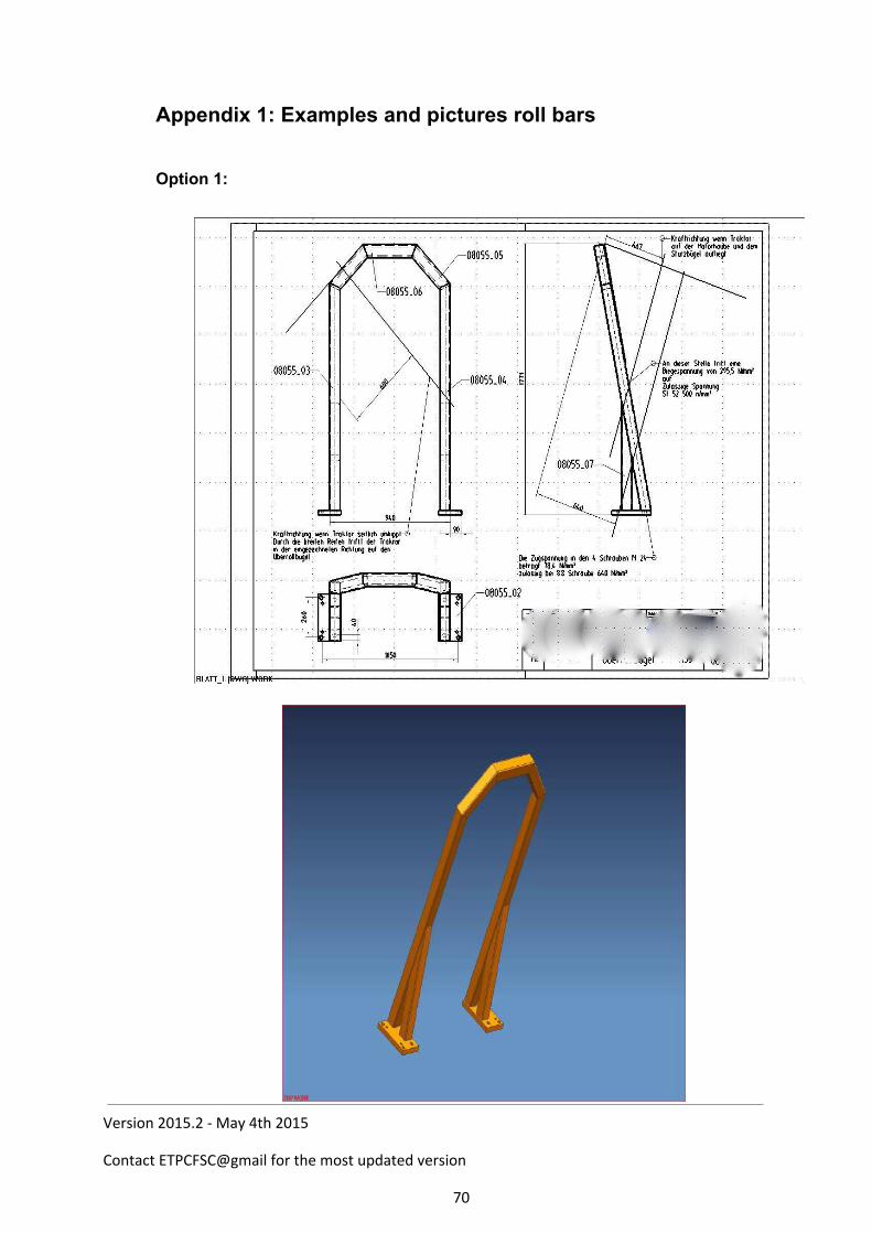
Appendix 1: Examples and pictures roll bars Option 1:
Version 2015.2 - May 4th 2015
Contact ETPCFSC@gmail for the most updated version
70

Version 2015.2 - May 4th 2015
Contact ETPCFSC@gmail for the most updated version
71
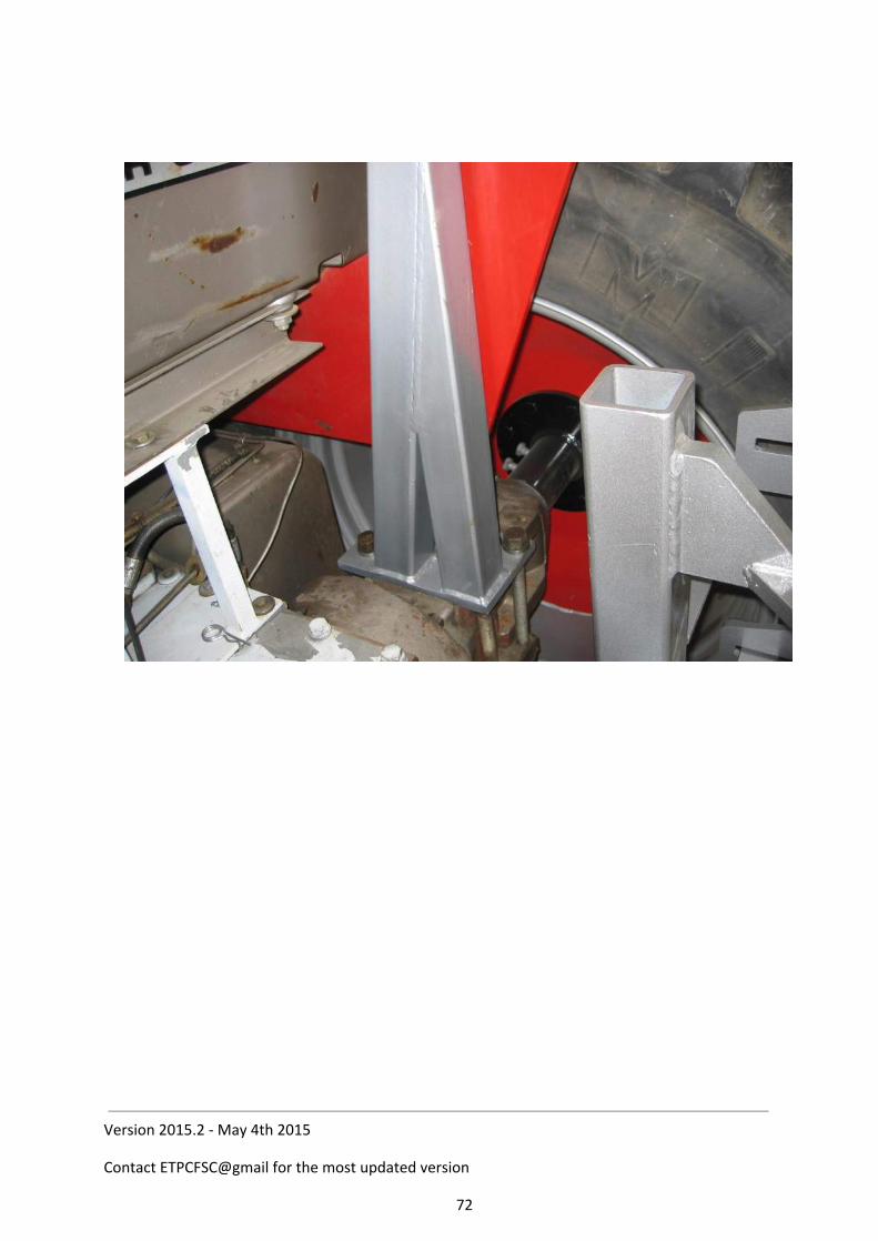
Version 2015.2 - May 4th 2015
Contact ETPCFSC@gmail for the most updated version
72
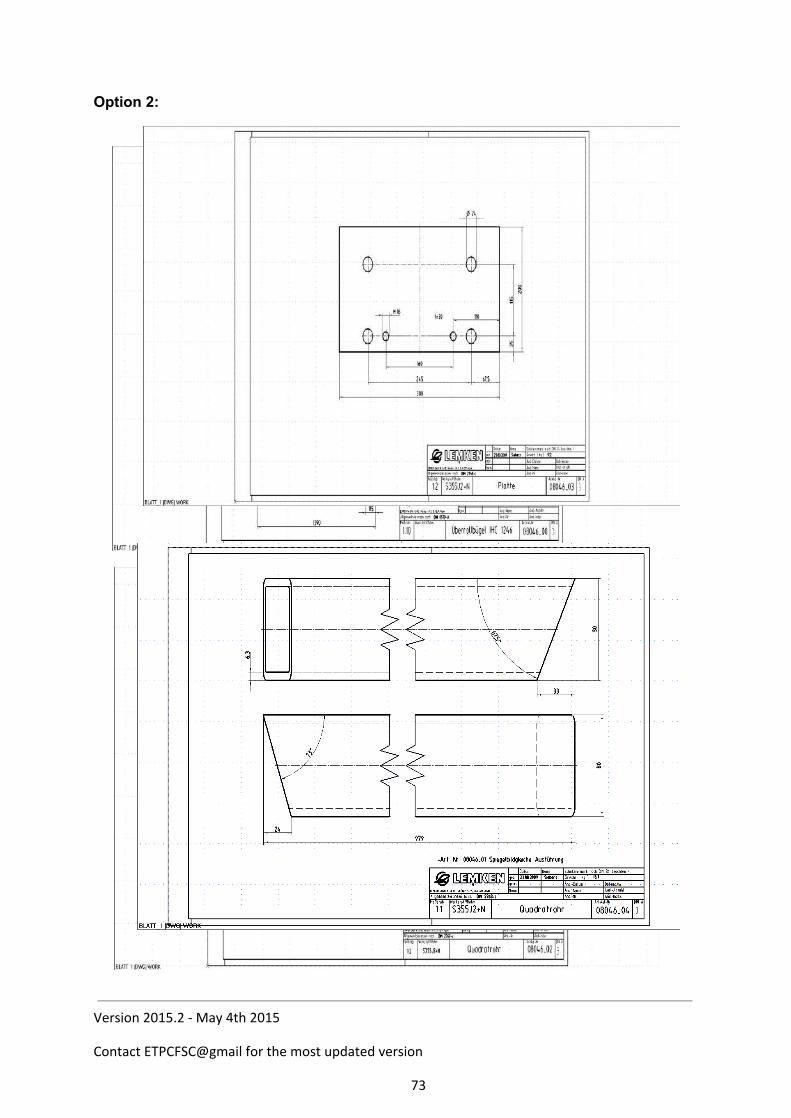
Option 2:
Version 2015.2 - May 4th 2015
Contact ETPCFSC@gmail for the most updated version
73
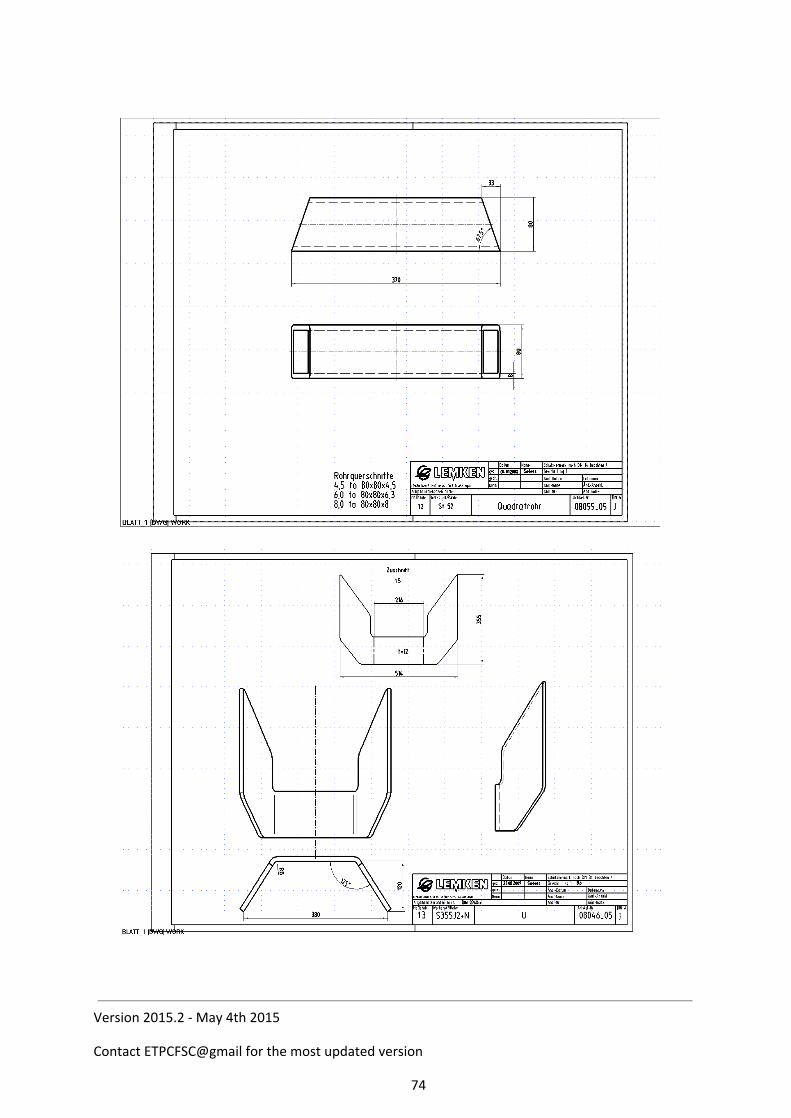
Version 2015.2 - May 4th 2015
Contact ETPCFSC@gmail for the most updated version
74
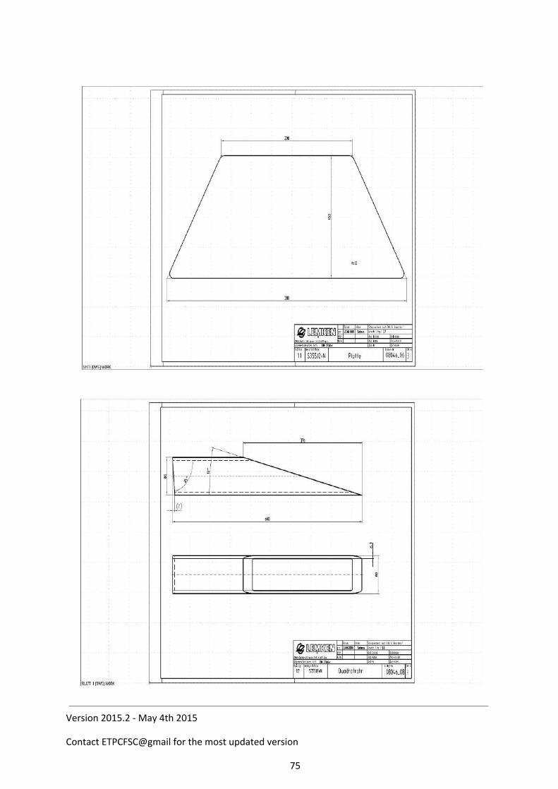
Version 2015.2 - May 4th 2015
Contact ETPCFSC@gmail for the most updated version
75
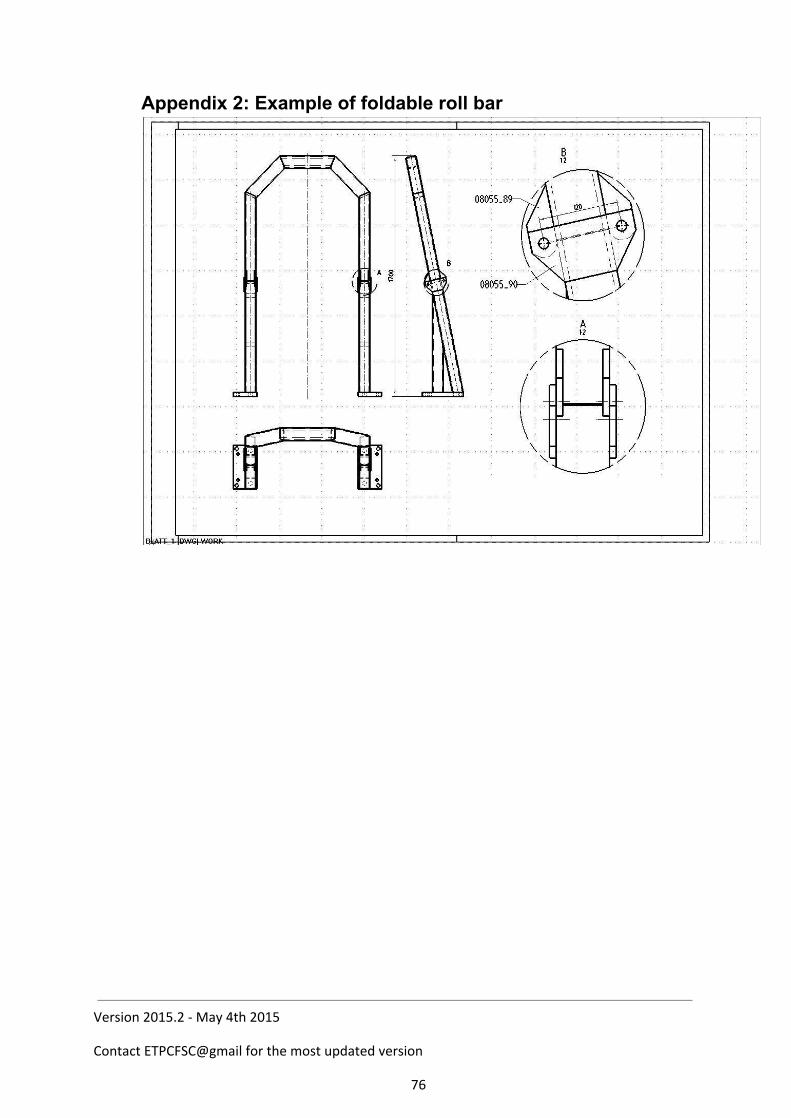
Appendix 2: Example of foldable roll bar
Version 2015.2 - May 4th 2015
Contact ETPCFSC@gmail for the most updated version
76
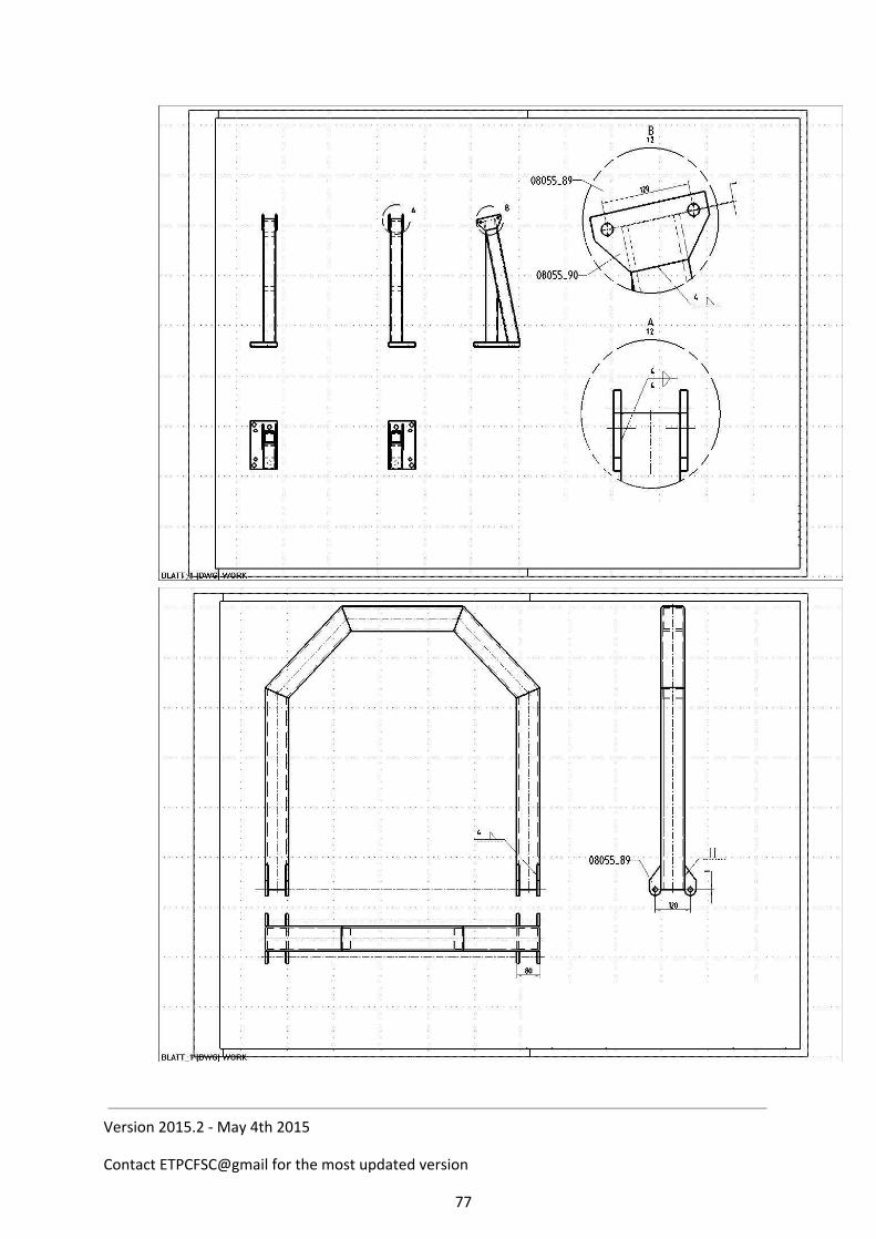
Version 2015.2 - May 4th 2015
Contact ETPCFSC@gmail for the most updated version
77

Version 2015.2 - May 4th 2015
Contact ETPCFSC@gmail for the most updated version
78

Version 2015.2 - May 4th 2015
Contact ETPCFSC@gmail for the most updated version
79
Appendix 3 (ETPC main rulebook, Chapter 2.D):
Clutches, flywheels, automatics and protection 1. The use of torque converters or automatic shifts will be permitted. 2. All automatic transmissions must be 360 degrees covered with a steel plate 3
mm thick. The steel cover around the torque converter must be covering the total width of the converter and must be at least 10 mm thick, or an ETPC approved blanket must be used. Plate or blanket is to extend from rear of engine block to front of tailhousing. Blanket must be fastened forward securely with two straps on each side, one fastening point above crankshaft centerline, and the other below crankshaft centerline. Blanket must have 150 mm of overlap. Straps must be 50 mm wide with no more than 25 mm spacing between each strap. The maximum age of a shatter blanket is five (5) years if not limited to a shorter period by manufacturer. In cases of doubt, it is the competitor’s responsibility to prove the age of the blanket.
3. All pulling vehicles using an automatic transmission must be equipped with a positive reversegear lockout.
4. All pulling vehicles using a flywheel and/or clutch assembly are required to use an ETPC approved item, producer must be on the manufacturers list of the ETPC Safety Program (see chapter 13 A). Only mechanical activated clutches permitted. No electronic, pneumatic or hydraulic device that effects the clutch system allowed. Hydraulic engagement allowed. The ETPC will allow homemade flywheel and clutch parts under the following criteria: All nonETPC Safety Program flywheel and/or clutch assemblies must fulfill the following minimum specifications: All parts must be made of steel plate or billet steel. POSITIVELY NO GRAY CAST IRON. Flywheel, pressure plate and pressure plate cover are allowed out of aluminum only wrought (billet) aluminum is adequate for pulling applications if mechanical properties are acceptable. A. Minimum mechanical properties (steel and aluminum):
Tensile strength 500 N/mm2 Yield strength 280 N/mm2
B. Maximum peripherical speed (rotating speed on the outer diameter of flywheel/clutch component) is 200 m/sec. Is 125 percent of maximum working speed (safety for overspeed). This means that maximum rotating speeds (working speed, by 1:1 engine/clutch rpm) are:
components max. 250 mm (10”) diam. = 12000 RPM components max. 280 mm (11”) diam. = 10500 RPM components max. 305 mm (12”) diam. = 10000 RPM components max. 318 mm (12,5”) diam. = 9500 RPM components max. 330 mm (13”) diam. = 9000 RPM
Version 2015.2 - May 4th 2015
Contact ETPCFSC@gmail for the most updated version
80
components max. 355 mm (14”) diam. = 8500 RPM components max. 380 mm (15”) diam. = 8000 RPM components max. 405 mm (16”) diam. = 7500 RPM components max. 430 mm (17”) diam. = 7000 RPM components max. 455 mm (18”) diam. = 6500 RPM components max. 480 mm (19”) diam. = 6000 RPM components max. 505 mm (20”) diam. = 5500 RPM
C. All capscrews and bolts used in the clutch assembly and to connect flywheel to crankshaft must meet class 10.9 (grade 8) or higher. No weldings and/or chemical milling allowed on any home made parts.
D. Drawings with measurements of all home made major components (flywheel, friction discs, floater plates, pressure plates and pressure plate cover) must always be with the pulling vehicle and be shown upon tech. inspectors request. A copy of all drawings and the manufacturer report must be send to and stored by the national Tech and Safety board. Manufacturer report shall include: name of all components used, with specification of used material and the
mechanical properties (max. yield strength, tensile strength etc.) material specification(s) with 3.1 .b certificate, signed by producer. all components must have on paper (and stamped in by producer):
identification number, producer name and date of produce. name of pulling vehicle and type of engine(s). max. rotating speed of flywheel/clutch assembly allowed by producer. Manufacturer’s name (and contact name); address; telephone and fax
numbers; email address; name and signature of responsible supervisor; signing date and place; any other appropriate information.
If point A,B, C and D above are fulfilled and according the rules national T&S board in cooperation with ETPC T&S board may give permission to use named flywheel/clutch components. After written permission, components can be used in ETPCpulling events.
5. All super stock and pro stock tractors are required to have an ETPC approved shatter blanket 430 mm wide and long enough to wrap around the bellhousing with at least 150 mm overlap; secured with six 50 mm wide nylon web straps with a steel Dring on one end and sewn the length of the blanket (except for overlap area) and long enough to pass through Dring and be tied in a saddle clinch; and with four 50 mm nylon web retaining straps each at the front and back of the blanket or an ETPC approved bell housing bolted to a steel engine plate, mm. 5 mm thick, inside the original clutch housing.
6. Super stocks and pro stocks factomade out of components can also use an ETPC approved bellhousing bolted to a steelengineplate, mm. 5 mm thick, instead of a blanket, in this application the use of a complete frame underneath the tractor is mandatory. Note: For ETPC approved items see Chapter 13 ETPC rulebook or appendix 6.
7. Straps to be separately fastened forward and to the rear of clutch/flywheel assembly All straps must be securely fastened and the blanket must be secured against the rear face of the block.
8. Fixes and/or changes, in whatever form, to shatter blankets may only be done by
Version 2015.2 - May 4th 2015
Contact ETPCFSC@gmail for the most updated version
81
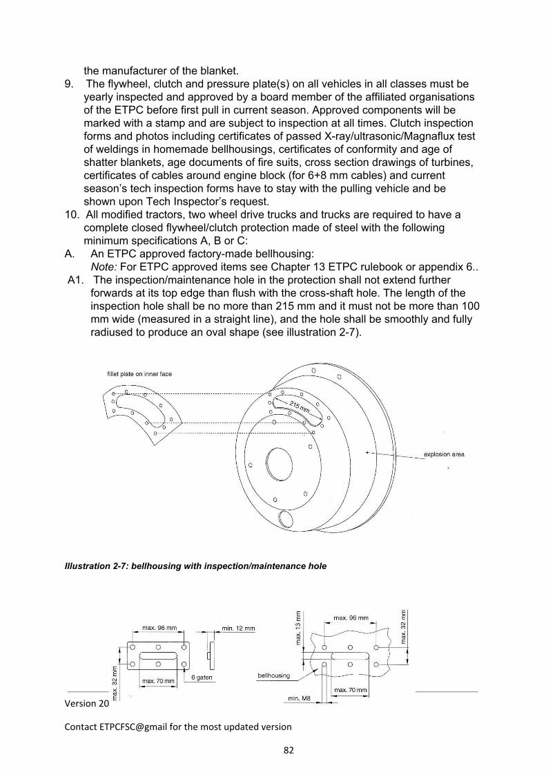
the manufacturer of the blanket. 9. The flywheel, clutch and pressure plate(s) on all vehicles in all classes must be
yearly inspected and approved by a board member of the affiliated organisations of the ETPC before first pull in current season. Approved components will be marked with a stamp and are subject to inspection at all times. Clutch inspection forms and photos including certificates of passed Xray/ultrasonic/Magnaflux test of weldings in homemade bellhousings, certificates of conformity and age of shatter blankets, age documents of fire suits, cross section drawings of turbines, certificates of cables around engine block (for 6+8 mm cables) and current season’s tech inspection forms have to stay with the pulling vehicle and be shown upon Tech Inspector’s request.
10. All modified tractors, two wheel drive trucks and trucks are required to have a complete closed flywheel/clutch protection made of steel with the following minimum specifications A, B or C:
A. An ETPC approved factorymade bellhousing: Note: For ETPC approved items see Chapter 13 ETPC rulebook or appendix 6..
A1. The inspection/maintenance hole in the protection shall not extend further forwards at its top edge than flush with the crossshaft hole. The length of the inspection hole shall be no more than 215 mm and it must not be more than 100 mm wide (measured in a straight line), and the hole shall be smoothly and fully radiused to produce an oval shape (see illustration 27).
Illustration 27: bellhousing with inspection/maintenance hole
Version 2015.2 - May 4th 2015
Contact ETPCFSC@gmail for the most updated version
82
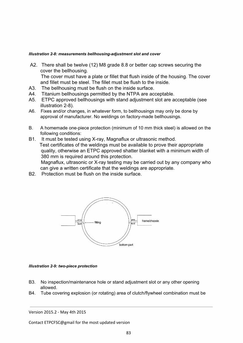
Illustration 28: measurements bellhousingadjustment slot and cover A2. There shall be twelve (12) M8 grade 8.8 or better cap screws securing the
cover the bellhousing. The cover must have a plate or fillet that flush inside of the housing. The cover
and fillet must be steel. The fillet must be flush to the inside. A3. The bellhousing must be flush on the inside surface. A4. Titanium bellhousings permitted by the NTPA are acceptable. A5. ETPC approved bellhousings with stand adjustment slot are acceptable (see
illustration 28). A6. Fixes and/or changes, in whatever form, to bellhousings may only be done by
approval of manufacturer. No weldings on factorymade bellhousings. B. A homemade onepiece protection (minimum of 10 mm thick steel) is allowed on the
following conditions: B1. It must be tested using Xray, Magnaflux or ultrasonic method. Test certificates of the weldings must be available to prove their appropriate quality, otherwise an ETPC approved shatter blanket with a minimum width of 380 mm is required around this protection. Magnaflux, ultrasonic or Xray testing may be carried out by any company who
can give a written certificate that the weldings are appropriate. B2. Protection must be flush on the inside surface. Illustration 29: twopiece protection
B3. No inspection/maintenance hole or stand adjustment slot or any other opening allowed.
B4. Tube covering explosion (or rotating) area of clutch/flywheel combination must be
Version 2015.2 - May 4th 2015
Contact ETPCFSC@gmail for the most updated version
83
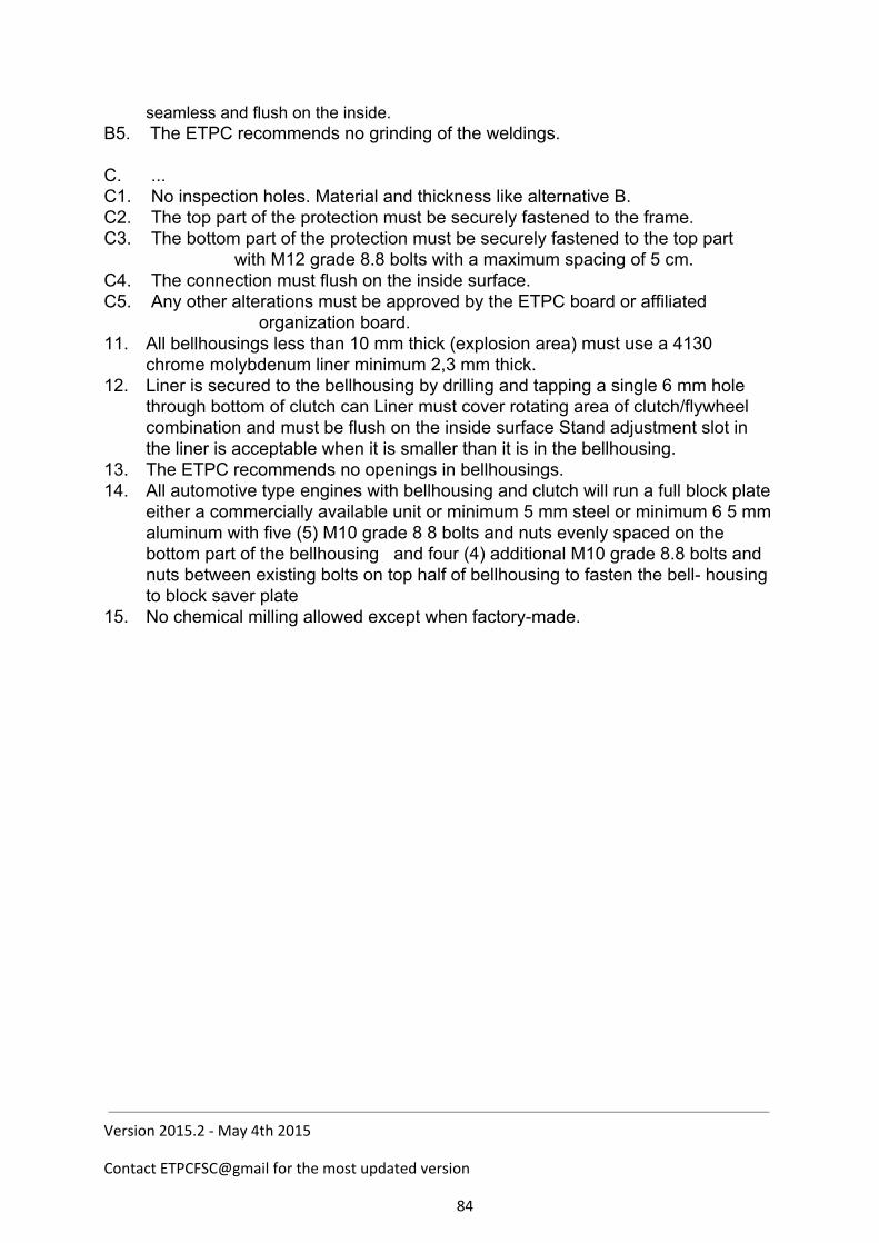
seamless and flush on the inside. B5. The ETPC recommends no grinding of the weldings. C. ... C1. No inspection holes. Material and thickness like alternative B. C2. The top part of the protection must be securely fastened to the frame. C3. The bottom part of the protection must be securely fastened to the top part
with M12 grade 8.8 bolts with a maximum spacing of 5 cm. C4. The connection must flush on the inside surface. C5. Any other alterations must be approved by the ETPC board or affiliated
organization board. 11. All bellhousings less than 10 mm thick (explosion area) must use a 4130
chrome molybdenum liner minimum 2,3 mm thick. 12. Liner is secured to the bellhousing by drilling and tapping a single 6 mm hole
through bottom of clutch can Liner must cover rotating area of clutch/flywheel combination and must be flush on the inside surface Stand adjustment slot in the liner is acceptable when it is smaller than it is in the bellhousing.
13. The ETPC recommends no openings in bellhousings. 14. All automotive type engines with bellhousing and clutch will run a full block plate
either a commercially available unit or minimum 5 mm steel or minimum 6 5 mm aluminum with five (5) M10 grade 8 8 bolts and nuts evenly spaced on the bottom part of the bellhousing and four (4) additional M10 grade 8.8 bolts and nuts between existing bolts on top half of bellhousing to fasten the bell housing to block saver plate
15. No chemical milling allowed except when factorymade.
Version 2015.2 - May 4th 2015
Contact ETPCFSC@gmail for the most updated version
84
Appendix 4, (ETPC main rulebook, Chapter 13):
ETPC SAFETY PROGRAMME
A. Approved manufacturers
Multiple disc clutch assemblies Turbine Blankets Ace Mfg & Parts Co. Belport, Belgium Applied Friction Techniques Atlas Tractor Company Bellhousings Carolina Precision Engines Browell Bellhousing Inc. Clutch Works Inc. Mr. Gasket/Lakewood Industries CMW Racing Probell Racing Crower Cams & Equipment Co. Trick Titanium Inc. Eagle Clutches, Finland EastWest Engineering Blower Restraints Devices Exedy America Corp. Deist Safety Equipment High Performance Clutch Corp. Don Gerardot Racing Hypermax Engineering Inc. J & S East Valley Garage L&T parts Inc. Mike KuhI Enterprises Mark Puwak Racing Speciality Automotive Engineering Inc. Mc Leod Industries, Inc. Stroud Safety Mr. Gasket/Hays Clutch TAK Racing Enterprises Performance Industries Racing Clutches Tayor Motorsports Products Ram Automotive Co. RF Enterprises Blower Restraints – Straps Rursch Specialty SES, Netherlands SSG Engineering Products Inc. Zimmermann Restraints, Germany Stroud Safety High Pertormance Harmonic Balancers Van der Waal Clutches, Netherlands ATI Racing Transmissions, Inc. Titan Speed Engineering B.H.J. Products
C.A.T. Power Engine Parts
Shatter Blankets Cyco System Pty, Ltd Belport, Belgium Innovators West Clifton Blankets, UK Precision Cam Drives Pty, Ltd Security Race Products Precision Parts Pty, Ltd Stroud Safety TCI Automotive Holland Blankets, Netherlands Vibratech/Unit of Index Corp.
Version 2015.2 - May 4th 2015
Contact ETPCFSC@gmail for the most updated version
85

ALL SAFETY ITEMS PERMITTED BY THE NTPA ARE ACCEPTED BY THE ETPC.
Version 2015.2 - May 4th 2015
Contact ETPCFSC@gmail for the most updated version
86
B. Age Limits for Safety Equipment The age of blower restraints, fire suits and shatter blankets must not exceed the limits given below.
1. Blower restraints The maximum age of blower restraints (straps) is six (6) years, if not given a shorter warranty by manufacturer.
2. Firesuits The maximum age of Nomex fire suits is six (6) years, for suits made of other materials two (2) years.
3. Shatter blankets The maximum age of shatter blankets is five (5) years, if not given a shorter warranty
by blanket manufacturer. The age of safety equipment has to be documented, see chapter 2, rule 9 in this
rulebook.
Version 2015.2 - May 4th 2015
Contact ETPCFSC@gmail for the most updated version
87
Appendix 5, (ETPC main rulebook, Chapter 14):
ROLL OVER PROTECTIONS
1. The Driver Roll Over Protection (ROP) has been designed in cooperation with specialists in order to protect the driver in the event of his vehicle tipping over during a tractor pulling competition. 2. The design, or the ROP built according to the given specifications, are not to be understood as an automatic guarantee, as for providing an always adequate protection
for the driver during an accident with the tractor. 3. The ROP specifications must be seen as a set of minimum requirements and advisory
guidelines. 4. Neither the ETPC Board, the T&S Board nor any of their members can be made responsible for consequences resulting from the application of the ROP specifications or
malfunction of the safety devices in question.
A. General Considerations 1. The construction must allow an easy exit for the driver in the event of a fire etc. 2. Tractors weighing more than 4000 kg are recommended to have a tube wall thickness
0.5 mm higher, or more, than specified. 3. If team drivers or tractor constructors think that the ROP constructions specified below
are not solid enough, they are free to make them stronger. 4. All NTPA certified ROP cages are permitted by the ETPC. 5. No ballast can be hung from or attached to any portion of the ROPstructure. Chassis
attachment is exempt of this rule.
B. Construction 1. Bending radius of all tubing should be as wide as possible, the minimum is two (2) times the outside diameter of the tube being bent. 2. All fastening bolts must be grade 8.8 or better, this must be clearly marked on the head
of the bolt. 3. All welded joints must be welded by an experienced professional; a steel filler metal must be employed that is compatible with the base metal. 4. All weldings must be done according to generally accepted welding practices. 5. No grinding on any welding. 6. All structural material for the ROP shall be seamless mild steel (carbon mechanical) tube or normalized chrome molybdene (DIN Norm 25 CrMo 4) seamless steel tube. 7. Tubing diameters and wall thicknesses are nominal measurements. 8. The dimensional locations of the main structural hoops and secondary tubing shown in
the figures are to be used as guidelines but must remain within 20% of the dimensions
Version 2015.2 - May 4th 2015
Contact ETPCFSC@gmail for the most updated version
88
specified in the figures. The maximum backward inclination of the cage is 20 degrees.
9. Tubing size and material shown in the figures and tables are minimum requirements! 10. There shall be a minimum of 50 mm between the main hoops and the driver s helmet,
both vertically and laterally, with the driver seated in normal position. 11. In order to avoid possible neck injury, the horizontal distance between the main hoops
and the driver’s helmet must not be over 200 mm.
12. It is recommended that the fastening construction of the ROP cage to the tractor frame is significantly stiffer than the ROP itself. 13. It is also recommended that the driver’s seat should be so constructed that it provides
adequate back and shoulder support during an accident. The seat should be mounted to the ROP cage, or the lower support structure with at least four (4) M8 grade 8.8 bolts.
The seat back should be bolted to the rear main hoops, and the seat should include a head rest.
14. The use of a 4point seat belt or better is mandatory. The seat belt must be attached to the rollcage.
C. Remarks The T&S Board will allow options ‘B’ or ‘C’ to be applied where ‘A’ is not technically possible (see drawings). 1. If ‘A’ is used, then both hoops from rear to front must be of onepiece tube. 2. If ‘B’ or ‘C’ is used, an additional tube ‘S’ must be added to the ROP, and the front hoops must be out of ONE piece. 3. If ‘C’ is used, then the both sidetoside hoops must be out of onepiece tube. In general, you should have as few weldings as possible and do them according to the drawings. Basically, no weldings are allowed on the main hoops, if you must weld a main hoop, please ask the T&S Board.
It is highly recommended to move the front hoop aft to allow quick exit in the event of fire or other mishap.
See next pages for drawings/illustrations.
Version 2015.2 - May 4th 2015
Contact ETPCFSC@gmail for the most updated version
89
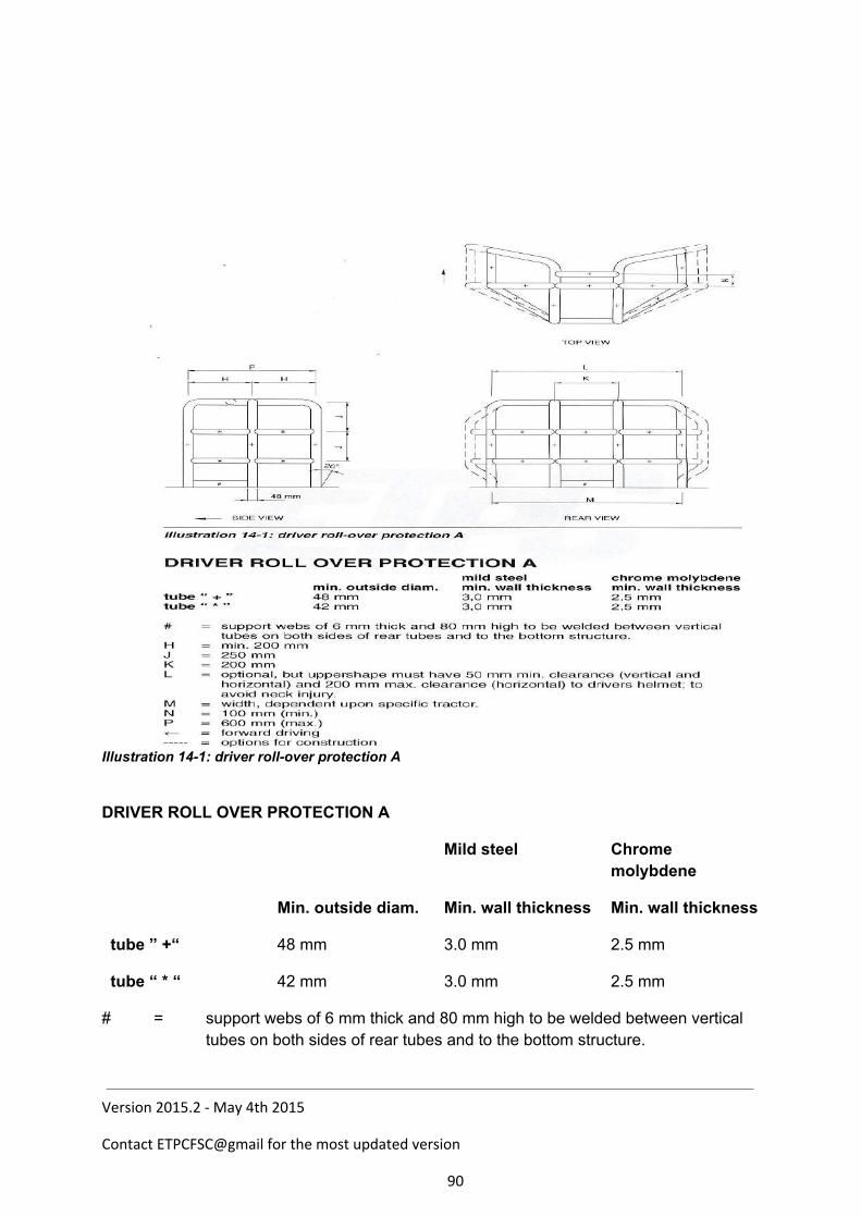
Illustration 141: driver rollover protection A
DRIVER ROLL OVER PROTECTION A
Mild steel Chrome molybdene
Min. outside diam. Min. wall thickness Min. wall thickness
tube ” +“ 48 mm 3.0 mm 2.5 mm
tube “ * “ 42 mm 3.0 mm 2.5 mm
# = support webs of 6 mm thick and 80 mm high to be welded between vertical tubes on both sides of rear tubes and to the bottom structure.
Version 2015.2 - May 4th 2015
Contact ETPCFSC@gmail for the most updated version
90
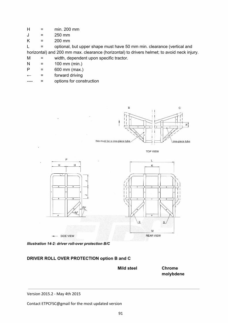
H = min. 200 mm J = 250 mm K = 200 mm L = optional, but upper shape must have 50 mm min. clearance (vertical and horizontal) and 200 mm max. clearance (horizontal) to drivers helmet; to avoid neck injury. M = width, dependent upon specific tractor. N = 100 mm (min.) P = 600 mm (max.) ← = forward driving = options for construction
Illustration 142: driver rollover protection B/C
DRIVER ROLL OVER PROTECTION option B and C
Mild steel Chrome molybdene
Version 2015.2 - May 4th 2015
Contact ETPCFSC@gmail for the most updated version
91
Min. outside diam. Min. wall thickness Min. wall thickness
tube ” +“ 48 mm 3.0 mm 2.5 mm
tube “ * “ 42 mm 3.0 mm 2.5 mm
# = support webs of 6 mm thick and 80 mm high to be welded between vertical tubes on both sides of rear tubes and to the bottom structure.
H = min. 200 mm J = 250 mm K = 200 mm L = optional, but upper shape must have 50 mm min. clearance (vertical and horizontal)
and 200 mm max. clearance (horizontal) to drivers helmet; to avoid neck injury. M = width, dependent upon specific tractor. N = 100 mm (min.) P = 600 mm (max.) ← = forward driving = options for construction
Version 2015.2 - May 4th 2015
Contact ETPCFSC@gmail for the most updated version
92
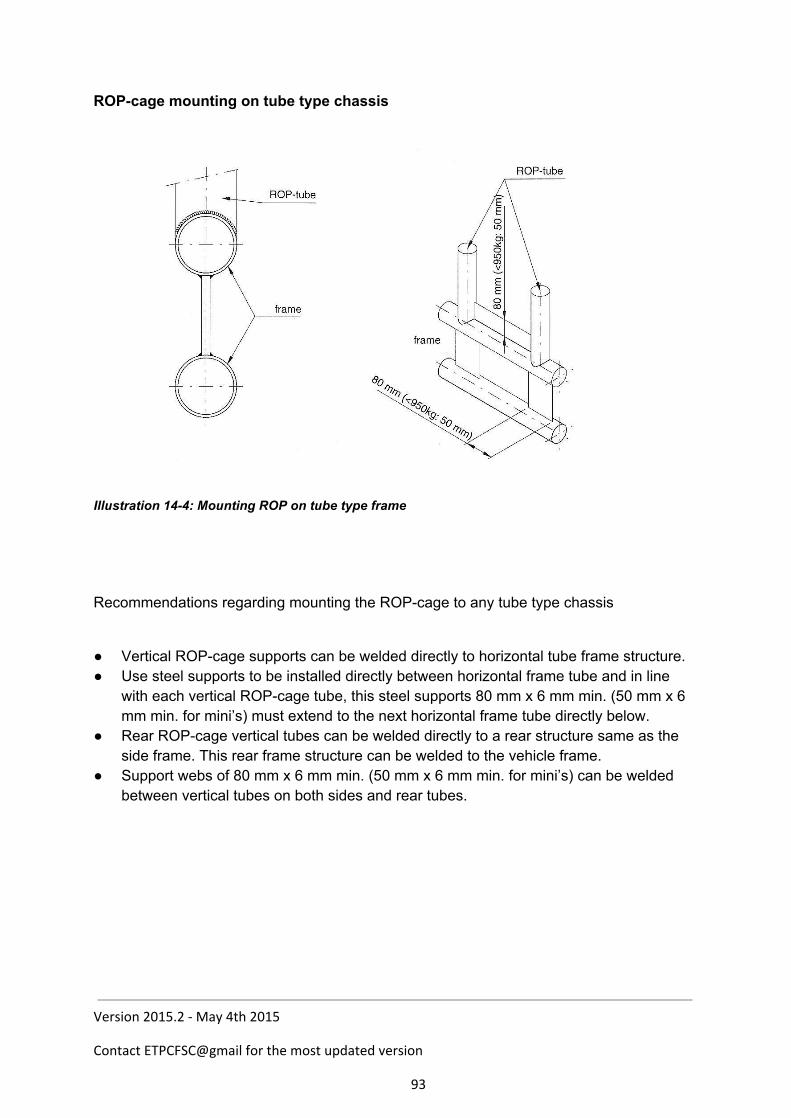
ROPcage mounting on tube type chassis
Illustration 144: Mounting ROP on tube type frame
Recommendations regarding mounting the ROPcage to any tube type chassis
Vertical ROPcage supports can be welded directly to horizontal tube frame structure. Use steel supports to be installed directly between horizontal frame tube and in line
with each vertical ROPcage tube, this steel supports 80 mm x 6 mm min. (50 mm x 6 mm min. for mini’s) must extend to the next horizontal frame tube directly below.
Rear ROPcage vertical tubes can be welded directly to a rear structure same as the side frame. This rear frame structure can be welded to the vehicle frame.
Support webs of 80 mm x 6 mm min. (50 mm x 6 mm min. for mini’s) can be welded between vertical tubes on both sides and rear tubes.
Version 2015.2 - May 4th 2015
Contact ETPCFSC@gmail for the most updated version
93
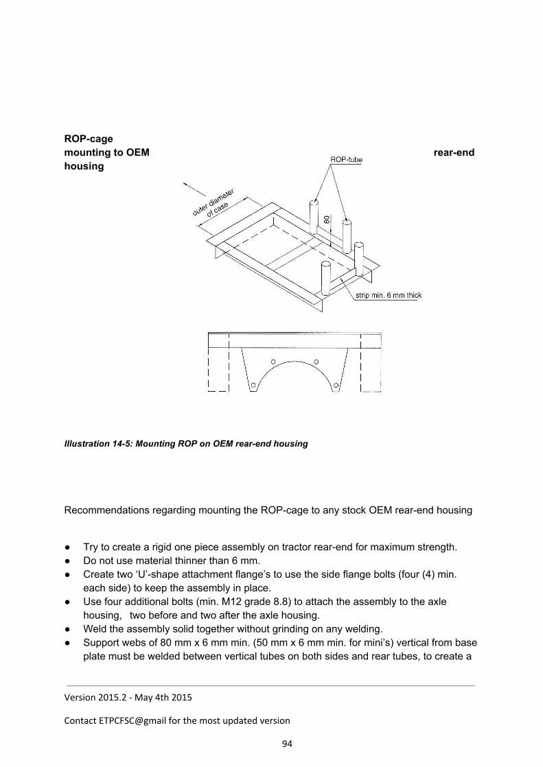
ROPcage mounting to OEM rearend housing
Illustration 145: Mounting ROP on OEM rearend housing
Recommendations regarding mounting the ROPcage to any stock OEM rearend housing
Try to create a rigid one piece assembly on tractor rearend for maximum strength. Do not use material thinner than 6 mm. Create two ‘U’shape attachment flange’s to use the side flange bolts (four (4) min.
each side) to keep the assembly in place. Use four additional bolts (min. M12 grade 8.8) to attach the assembly to the axle
housing, two before and two after the axle housing. Weld the assembly solid together without grinding on any welding. Support webs of 80 mm x 6 mm min. (50 mm x 6 mm min. for mini’s) vertical from base
plate must be welded between vertical tubes on both sides and rear tubes, to create a
Version 2015.2 - May 4th 2015
Contact ETPCFSC@gmail for the most updated version
94

solid connection from ROPcage to rearend.
Version 2015.2 - May 4th 2015
Contact ETPCFSC@gmail for the most updated version
95
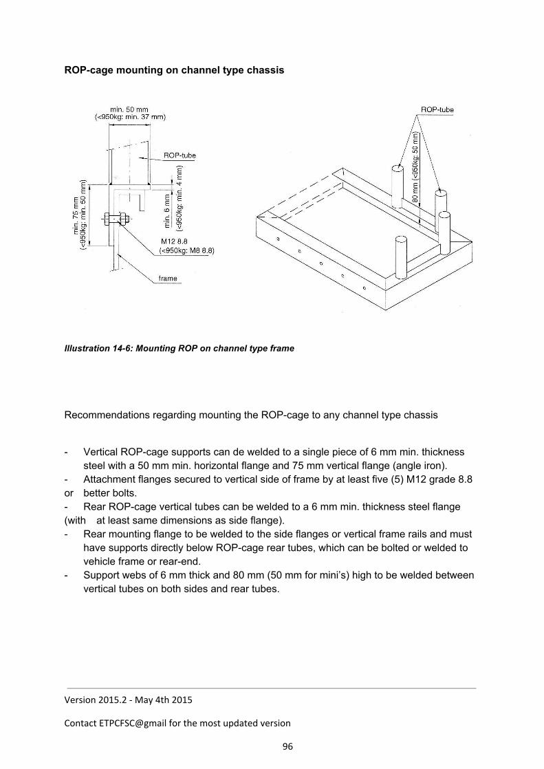
ROPcage mounting on channel type chassis
Illustration 146: Mounting ROP on channel type frame
Recommendations regarding mounting the ROPcage to any channel type chassis
Vertical ROPcage supports can de welded to a single piece of 6 mm min. thickness steel with a 50 mm min. horizontal flange and 75 mm vertical flange (angle iron).
Attachment flanges secured to vertical side of frame by at least five (5) M12 grade 8.8 or better bolts. Rear ROPcage vertical tubes can be welded to a 6 mm min. thickness steel flange (with at least same dimensions as side flange). Rear mounting flange to be welded to the side flanges or vertical frame rails and must
have supports directly below ROPcage rear tubes, which can be bolted or welded to vehicle frame or rearend.
Support webs of 6 mm thick and 80 mm (50 mm for mini’s) high to be welded between vertical tubes on both sides and rear tubes.
Version 2015.2 - May 4th 2015
Contact ETPCFSC@gmail for the most updated version
96
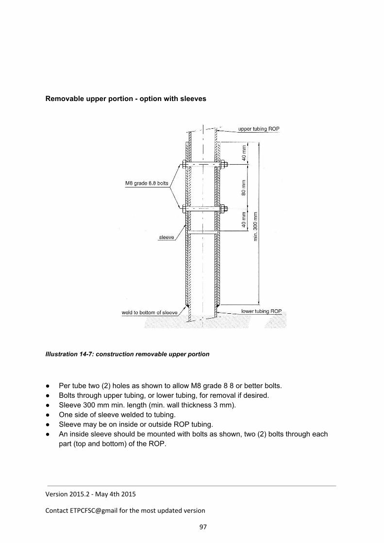
Removable upper portion option with sleeves
Illustration 147: construction removable upper portion
Per tube two (2) holes as shown to allow M8 grade 8 8 or better bolts. Bolts through upper tubing, or lower tubing, for removal if desired. Sleeve 300 mm min. length (min. wall thickness 3 mm). One side of sleeve welded to tubing. Sleeve may be on inside or outside ROP tubing. An inside sleeve should be mounted with bolts as shown, two (2) bolts through each
part (top and bottom) of the ROP.
Version 2015.2 - May 4th 2015
Contact ETPCFSC@gmail for the most updated version
97