Embed Size (px)
Citation preview
FANFARE 102
TYPE ACCEPTED - RB 249
INSTRUCTION
MANUAL
TABLE OF CONTENTS
Page
SECTION I, INTRODUCTION 1
PLL Frequency Synthesizers 1
SECTION II, INSTALLATION INSTRUCTIONS 2
Mobile Station 5 Base Station Installation 6 Antenna and Cable Information 6 Voltage Standing Wave (VSWR) Measurements 8 External Speaker Connections 8
SECTION III, STATION OPERATION 10
Function of the Controls, Indicators and Connectors 10
Good CB Practices 13 Receiver Operation 15 Transmitter Operation 16 External Speaker Operation 17
SECTION IV, TECHNICAL DATA/SERVICE ? MAINTENANCE 18
General Description 18 Nominal Specifications 18 Service and Maintenance 20 Special Replacement Parts List 23
LIMITED WARRANTY Back Cover
FIGURES AND DIAGRAMS
Figure 1, Typical Vehicle Mounting Bracket Installation 3 Figure 2, Power Cable, Lead Identification Diagram 4 Figure 3, Mobile Antenna Location Diagram S Figure 4, Cable Connection Assembly Diagram 7 Figure 5, External Speaker Cable Diagram 9 Figure 6, Controls, Indicators and Connectors 11 Figure 7, Schematic Diagram 21/22
PLL FREQUENCY SYNTHESIZER
Most Citizens Band Transceivers in the past used Frequency Synthesizers utilizing 12 or more quartz crystals to gener-ate the various radio signals for receiving and transmitting the assigned CB channels. The frequency stability of each channel, when receiving or transmitting, was dependent largely upon the crystals used to generate the frequencies for that channel. The frequency accuracy and stability of one channel was often better than another.
Citizens Band transceivers of recent design, such as the transceiver you have purchased, utilize the most advanced design of frequency synthesizers called Phase Locked Loop (PLL) Frequency Synthesizers. These synthesizers utilize a minimal number of crystals as reference frequencies from which transmitting and receiving frequencies are developed. The transmitting and receiving frequencies are stabilized by phase comparing to the reference frequency and thus pro-viding a phase-locked loop.
There are several types of PLL circuits in use; the one your transceiver uses incorporates the best features of these de-signs. Your transceiver uses crystal controlled standards with digital type programmable frequency dividers for selec-tion of the channel frequencies, which are always locked to the reference frequency. If for any reason the PLL is not "locked" the transmitter will not transmit.
SECTION II , INSTALLATION
A. Mobile Station
CAREFULLY READ ALL INSTALLATION INFORMATION IN THIS MAN-UAL BEFORE ATTEMPTING TO INSTALL THE TRANSCEIVER IN A VEHICLE OR AS A BASE STATION.
1. Location
a) Locate the transceiver under the dash or on the hump of the vehicle. DO NOT POSITION ON TOP OF THE DASH OR ANY LOCATION THAT WILL INTERFERE WITH THE OPERATION OF THE VEHICLE.
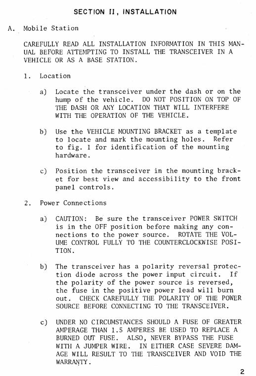
b) Use the VEHICLE MOUNTING BRACKET as a template to locate and mark the mounting holes. Refer to fig. 1 for identification of the mounting hardware.
c) Position the transceiver in the mounting brack-et for best view and accessibility to the front panel controls.
2. Power Connections
a) CAUTION: Be sure the transceiver POWER SWITCH is in the OFF position before making any con-nections to the power source. ROTATE THE VOL-UME CONTROL FULLY TO THE COUNTERCLOCKWISE POSI-TION.
b) The transceiver has a polarity reversal protec-tion diode across the power input circuit. If the polarity of the power source is reversed, the fuse in the positive power lead will burn out. CHECK CAREFULLY THE POLARITY OF THE POWER SOURCE BEFORE CONNECTING TO THE TRANSCEIVER.
c) UNDER NO CIRCUMSTANCES SHOULD A FUSE OF GREATER AMPERAGE THAN 1.5 AMPERES BE USED TO REPLACE A BURNED OUT FUSE. ALSO, NEVER BYPASS THE FUSE WITH A JUMPER WIRE. IN EITHER CASE SEVERE DAM-AGE WILL RESULT TO THE TRANSCEIVER AND VOID THE WARRANTY.
2
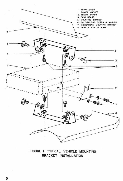
I . TRANSCEIVER 2. RUBBER WASHER 3. THUMB SCREW 4. DASH BOARD 5. MOUNTING BRACKET 6. SELF-TAPPING SCREW & WASHER 7. MICROPHONE MOUNTING BRACKET 8. VEHICLE CENTER HUMP
FIGURE I, TYPICAL VEHICLE MOUNTING BRACKET INSTALLATION
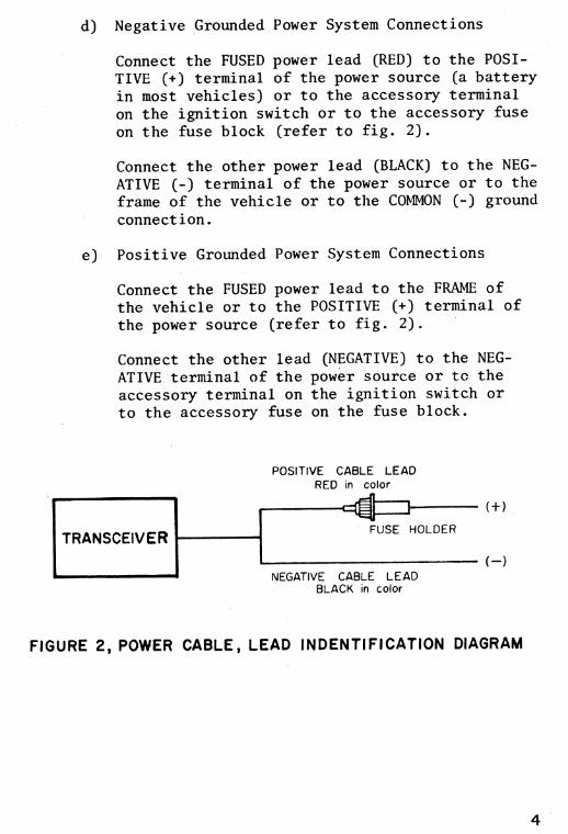
d) Negative Grounded Power System Connections
Connect the FUSED power lead (RED) to the POSI-TIVE (+) terminal of the power source (a battery in most vehicles) or to the accessory terminal on the ignition switch or to the accessory fuse on the fuse block (refer to fig. 2).
Connect the other power lead (BLACK) to the NEG-ATIVE (-) terminal of the power source or to the frame of the vehicle or to the COMMON (-) ground connection.
e) Positive Grounded Power System Connections
Connect the FUSED power lead to the FRAME of the vehicle or to the POSITIVE (+) terminal of the power source (refer to fig. 2).
Connect the other lead (NEGATIVE) to the NEG-ATIVE terminal of the power source or to the accessory terminal on the ignition switch or to the accessory fuse on the fuse block.
POSITIVE CABLE LEAD RED in color
TRANSCEIVER
NEGATIVE CABLE LEAD BLACK in color
FUSE HOLDER
(+)
(—)
FIGURE 2, POWER CABLE, LEAD INDENTIFICATION DIAGRAM
3. Microphone
Connect microphone plug into transceiver jack and mount microphone hanger as follows:
a) In the package containing the mounting hardware, there are screws and the microphone hanging bracket. For convenience, locate the hanger on the dashboard within easy reach of the opera-tor, so that the microphone may be grasped with-out the operator having to take his eyes off the road.
When an approximate location has been chosen, use the hanger as a template and center punch the centers of the two #30 (.120 Dia.) holes, drill and mount the hanger with the two #6 self-tapping screws.
4. Mobile Station Antennas
CAUTION: NEVER OPERATE YOUR TRANSCEIVER WITHOUT A PROPERLY MATCHED ANTENNA.
Many styles and types of mobile antennas are avail-able for installation on just about every type of vehicle, including boats and aircraft. You should discuss this with your dealer.
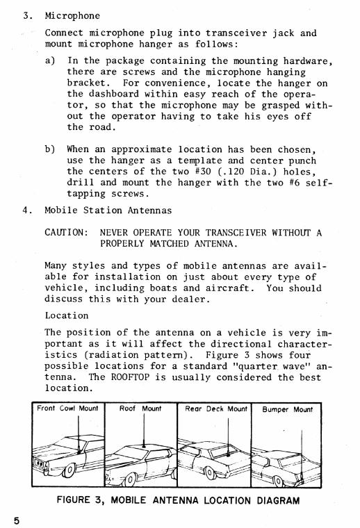
Location
The position of the antenna on a vehicle is very im-portant as it will affect the directional character-istics (radiation pattern). Figure 3 shows four possible locations for a standard "quarter, wave" an-tenna. The ROOFTOP is usually considered the best location.
Front Cowl
._—__-_,------_______•
III,
Mount
541.11
Roof Mount Rear Deck
OPIMIS,
Mount
_-'
Bumper Mount
+-. -- 4
4
--
----'
FIGURE 3, MOBILE ANTENNA LOCATION DIAGRAM
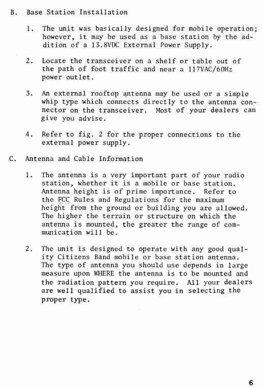
B. Base Station Installation
1. The unit was basically designed for mobile operation; however, it may be used as a base station by the ad-dition of a 13.8VDC External Power Supply.
2. Locate the transceiver on a shelf or table out of the path of foot traffic and near a 117VAC/60Hz power outlet.
3. An external rooftop 4ntenna may be used or a simple whip type which connects directly to the antenna con-nector on the transceiver. Most of your dealers can give you advise.
4. Refer to fig. 2 for the proper connections to the external power supply.
C. Antenna and Cable Information
1. The antenna is a very important part of your radio station, whether it is a mobile or base station. Antenna height is of prime importance. Refer to the FCC Rules and Regulations for the maximum height from the ground or building you are allowed. The higher the terrain or structure on which the antenna is mounted, the greater the range of com-munication will be.
2. The unit is designed to operate with any good qual-ity Citizens Band mobile or base station antenna. The type of antenna you should use depends in large measure upon WHERE the antenna is to be mounted and the radiation pattern you require. All your dealers are well qualified to assist you in selecting the proper type.
6
SOLDER THRU HOLES (3) TO BRAIDED SHIELD
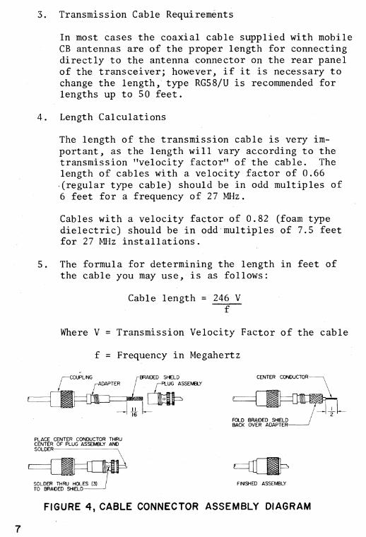
COUPLING BRAIDED SHIELD CENTER CONDUCTOR ADAPTER PLUG ASSEMBLY
FOLD BRAIDED SHIELD BACK OVER ADAPTER
PLACE CENTER CONDUCTOR THRU CENTER OF PLUG ASSEMBLY AND SOLDER
FIGURE 4, CABLE CONNECTOR ASSEMBLY DIAGRAM
FINISHED ASSEMBLY
3. Transmission Cable Requirements
In most cases the coaxial cable supplied with mobile CB antennas are of the proper length for connecting directly to the antenna connector on the rear panel of the transceiver; however, if it is necessary to change the length, type RG58/U is recommended for lengths up to 50 feet.
4. Length Calculations
The length of the transmission cable is very im-portant, as the length will vary according to the transmission "velocity factor" of the cable. The length of cables with a velocity factor of 0.66 (regular type cable) should be in odd multiples of 6 feet for a frequency of 27 MHz.
Cables with a velocity factor of 0.82 (foam type dielectric) should be in odd multiples of 7.5 feet for 27 MHz installations.
5. The formula for determining the length in feet of the cable you may use, is as follows:
Cable length = 246 V f
Where V = Transmission Velocity Factor of the cable
f = Frequency in Megahertz
7
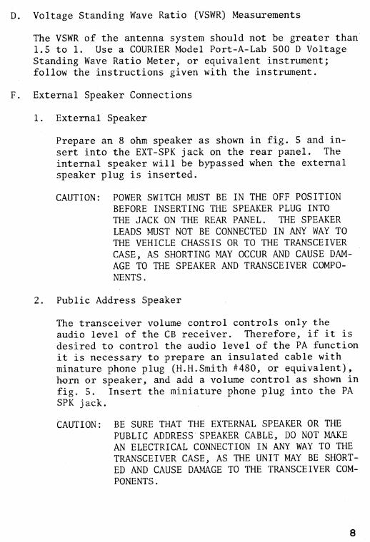
D. Voltage Standing Wave Ratio (VSWR) Measurements
The VSWR of the antenna system should not be greater than 1.5 to 1. Use a COURIER Model Port-A-Lab 500 D Voltage Standing Wave Ratio Meter, or equivalent instrument; follow the instructions given with the instrument.
F. External Speaker Connections
1. External Speaker
Prepare an 8 ohm speaker as shown in fig. 5 and in-sert into the EXT-SPK jack on the rear panel. The internal speaker will be bypassed when the external speaker plug is inserted.
CAUTION: POWER SWITCH MUST BE IN THE OFF POSITION BEFORE INSERTING THE SPEAKER PLUG INTO THE JACK ON THE REAR PANEL. THE SPEAKER LEADS MUST NOT BE CONNECTED IN ANY WAY TO THE VEHICLE CHASSIS OR TO THE TRANSCEIVER CASE, AS SHORTING MAY OCCUR AND CAUSE DAM-AGE TO THE SPEAKER AND TRANSCEIVER COMPO-NENTS.
2. Public Address Speaker
The transceiver volume control controls only the audio level of the CB receiver. Therefore, if it is desired to control the audio level of the PA function it is necessary to prepare an insulated cable with minature phone plug (H.H.Smith #480, or equivalent), horn or speaker, and add a volume control as shown in fig. 5. Insert the miniature phone plug into the PA SPK jack.
CAUTION: BE SURE THAT THE EXTERNAL SPEAKER OR THE PUBLIC ADDRESS SPEAKER CABLE, DO NOT MAKE AN ELECTRICAL CONNECTION IN ANY WAY TO THE TRANSCEIVER CASE, AS THE UNIT MAY BE SHORT-ED AND CAUSE DAMAGE TO THE TRANSCEIVER COM-PONENTS.
8
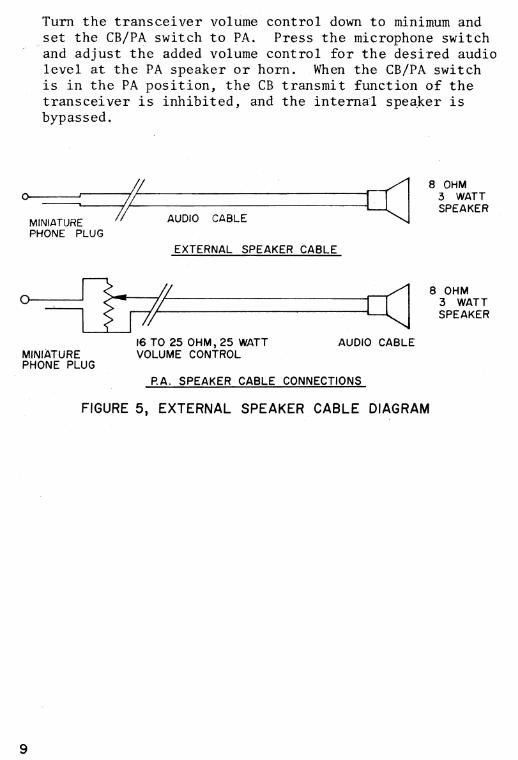
8 OHM 3 WATT SPEAKER
Turn the transceiver volume control down to minimum and set the CB/PA switch to PA. Press the microphone switch and adjust the added volume control for the desired audio level at the PA speaker or horn. When the CB/PA switch is in the PA position, the CB transmit function of the transceiver is inhibited, and the internal speaker is bypassed.
8 OHM 3 WATT SPEAKER
MINIATURE PHONE PLUG
AUDIO CABLE
EXTERNAL SPEAKER CABLE
16 TO 25 OHM, 25 WATT
AUDIO CABLE MINIATURE
VOLUME CONTROL PHONE PLUG
P.A. SPEAKER CABLE CONNECTIONS
FIGURE 5, EXTERNAL SPEAKER CABLE DIAGRAM
9
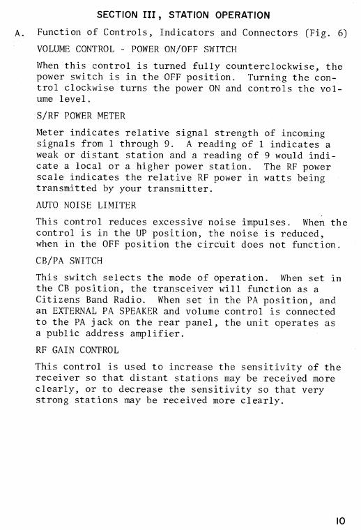
SECTION III , STATION OPERATION
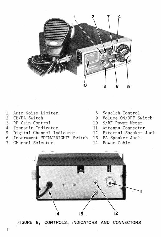
A. Function of Controls, Indicators and Connectors (Fig. 6)
VOLUME CONTROL - POWER ON/OFF SWITCH
When this control is turned fully counterclockwise, the power switch is in the OFF position. Turning the con-trol clockwise turns the power ON and controls the vol-ume level.
S/RF POWER METER
Meter indicates relative signal strength of incoming signals from 1 through 9. A reading of 1 indicates a weak or distant station and a reading of 9 would indi-cate a local or a higher power station. The RF power scale indicates the relative RF power in watts being transmitted by your transmitter.
AUTO NOISE LIMITER
This control reduces excessive noise impulses. When the control is in the UP position, the noise is reduced, when in the OFF position the circuit does not function.
CB/PA SWITCH
This switch selects the mode of operation. When set in the CB position, the transceiver will function as a Citizens Band Radio. When set in the PA position, and an EXTERNAL PA SPEAKER and volume control is connected to the PA jack on the rear panel, the unit operates as a public address amplifier.
RF GAIN CONTROL
This control is used to increase the sensitivity of the receiver so that distant stations may be received more clearly, or to decrease the sensitivity so that very strong stations may be received more clearly.
10
I0 8 5
7 4
1 Auto Noise Limiter 2 CB/PA Switch 3 RF Gain Control 4 Transmit Indicator 5 Digital Channel Indicator 6 Instrument "DIM/BRIGHT" Switch 7 Channel Selector
8 Squelch Control 9 Volume ON/OFF Switch 10 S/RF Power Meter 11 Antenna Connector 12 External Speaker Jack 13 PA Speaker Jack 14 Power Cable
14 13 12
FIGURE 6, CONTROLS, INDICATORS AND CONNECTORS
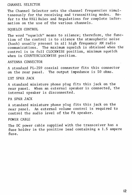
CHANNEL SELECTOR
The Channel Selector sets the channel frequencies simul-taneously for the receiving and transmitting modes. Re-fer to the RB11 Rules and Regulations for complete infor-mation on the use of the various channels.
SQUELCH CONTROL
The word "squelch" means to silence; therefore, the func-tion of the control is to silence the atmospheric noise (hash) usually present in all high frequency AM radio communications. The maximum squelch is obtained when the control is in full CLOCKWISE position, minimum squelch when in COUNTERCLOCKWISE position.
ANTENNA CONNECTOR
A standard PL-259 coaxial connector fits this connector on the rear panel. The output impedance is 50 ohms.
EXT SPKR JACK
A standard miniature phone plug fits this jack on the rear panel. When an external speaker is connected, the internal speaker is disconnected.
PA SPKR JACK
A standard miniature phone plug fits this jack on the rear panel. An external volume control is required to control the audio level of the PA speaker.
POWER CABLE
The DC power cable supplied with the transceiver has a fuse holder in the positive lead containing a 1.5 ampere fuse.
12
B. Good CB Practices
In order that all CB operators may obtain maximum bene-fit from their CB radio station, the we strongly urge all CB radio operators to observe the following "Good CB Practices":
1. Channel Selection
In selecting a channel for your station, it is very important that the following factors be considered:
a. Channel 6 is the recommended calling channel.
b. There are only a limited number of channels available for use by all CB stations.
c. Channel 5 may be used for emergency communica-tions only (situations which require immediate assistance to a motorist, etc.).
d. Any one of the other channels are to be used to conduct personal and business radio communica-tions.
2. Channel Usage
Cooperate to the fullest extent possible in sharing the CB channels. Always be courteous and consid-erate when using a channel. In order to assure that all CB operators will have an equal opportunity to use_the frequencies, radio communications between CB stations (interstation) must.be limited to no longer than 5 continuous minutes to be followed by a silent period of at least one minute. Operators should restrict their time on the air to a practical minimum.
13
The importance of all CB users disciplining them-, selves from needlessly transmitting for long periods of time cannot be stressed enough.
3. Identification
See RB14 for examples of communication proceedures. Identify your radio transmissions with your own licensed call sign before and after each transmiss-ion.- This call sign is unique in that it is unlike any other CB radio station call sign. Be proud to identify your radio transmissions with it. "Nick-names" or "handles" may also be used to identify your radio transmissions provided they are accompanied by the assigned call sign. It is not necessary to transmit the call sign of the station with whom you are talking.
4. Equipment
Have frequency, power and modulation measurements made at regular intervals. Do not tamper with the equipment. A licensed commercial technician is re-quired to perform any adjustments that might affect the proper operation of the transceiver.
5. Promote "Good CB Practices"
Encourage other CB users to follow the above sug-gested practices.
If all CB users make a serious attempt to understand and follow the above recommended practices, we be-lieve efficient utilization of the shared CB chan-nels will be maximized.
6. Telecom approved phonetic alphabet
A Alpha B Bravo C Chalie D Delta E Echo F Foxtrot G Golf H Hotel I India
J Juliet S Sierra K Kilo T Tango L Lima U Uniform M Mike V Victor N November W Whisky O Oscar X X-ray P Papa Y Yankee Q Quebec Z Zulu R Rameo
14
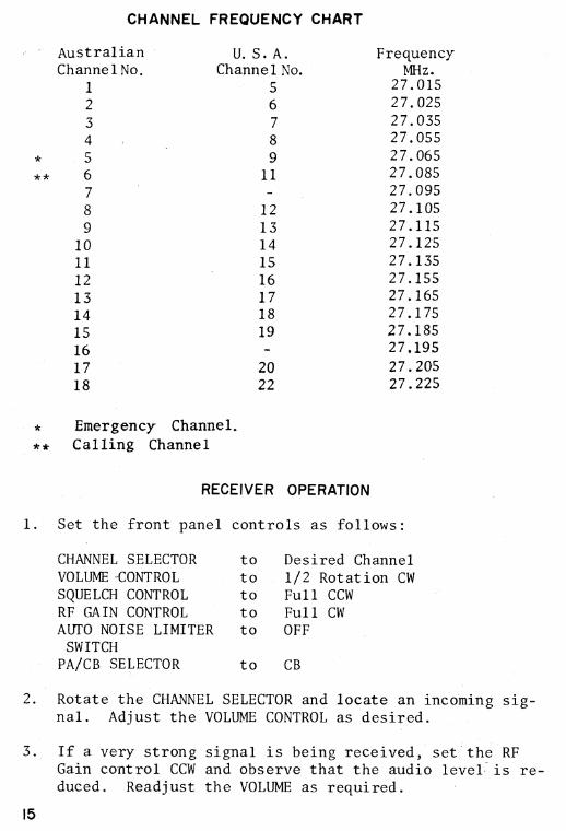
CHANNEL FREQUENCY CHART
Australian
U. S. A. Frequency Channel No. Channel No. MHz.
1
5
27.015
2
6
27.025
3
7
27.035
4
8
27.055
5
9
27.065 ** 6
11
27.085
7
27.095
8
12
27.105
9
13
27.115
10
14
27.125
11
15
27.135
12
16
27.155
13
17
27.165
14
18
27.175
15
19
27.185
16
27.195
17
20
27.205
18
22
27.225
Emergency Channel. ** Calling Channel
RECEIVER OPERATION
1. Set the front panel
CHANNEL SELECTOR VOLUME -CONTROL SQUELCH CONTROL RF GAIN CONTROL AUTO NOISE LIMITER
SWITCH PA/CB SELECTOR
controls as follows:
to Desired Channel to 1/2 Rotation CW to Full CCW to Full CW to OFF
to CB
2. Rotate the CHANNEL SELECTOR and locate an incoming sig-nal. Adjust the VOLUME CONTROL as desired.
3. If a very strong signal is being received, set the RF Gain control CCW and observe that the audio level - is re-duced. Readjust the VOLUME as required.
15
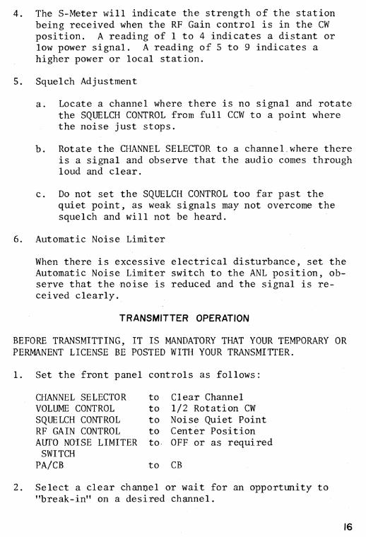
4. The S-Meter will indicate the strength of the station being received when the RF Gain control is in the CW position. A reading of 1 to 4 indicates a distant or low power signal. A reading of 5 to 9 indicates a higher power or local station.
5. Squelch Adjustment
a. Locate a channel where there is no signal and rotate the SQUELCH CONTROL from full CCW to a point where the noise just stops.
b. Rotate the CHANNEL SELECTOR to a channel .where there is a signal and observe that the audio comes through loud and clear.
c. Do not set the SQUELCH CONTROL too far past the quiet point, as weak signals may not overcome the squelch and will not be heard.
6. Automatic Noise Limiter
When there is excessive electrical disturbance, set the Automatic Noise Limiter switch to the ANL position, ob-serve that the noise is reduced and the signal is re-ceived clearly.
TRANSMITTER OPERATION
BEFORE TRANSMITTING, IT IS MANDATORY THAT YOUR TEMPORARY OR PERMANENT LICENSE BE POSTED WITH YOUR TRANSMITTER.
1. Set the front panel
CHANNEL SELECTOR VOLUME CONTROL SQUELCH CONTROL RF GAIN CONTROL AUTO NOISE LIMITER
SWITCH PA/CB
controls as follows:
to Clear Channel to 1/2 Rotation CW to Noise Quiet Point to Center Position to. OFF or as required
to CB
2. Select a clear channel or wait for an opportunity to "break-in" on a desired channel.
16
3. Position the microphone approximately 2 inches from your mouth and hold the Press-to-Talk switch down. Speak in a normal tone and level of voice, do not speak for more than five minutes. Release the Press-to-Talk switch and listen for the reply.
4. Double numbers on the Channel Selector The large outside numbers on the channel selector indicate the official Australian channels. The smaller inside numbers indicate the equivalent American channel numbers allowing ease of cross reference with other operators using old 23 channel transceivers not built to the largest Australian specification. Note that the large numbers are the official ones.
PUBLIC ADDRESS AND EXTERNAL SPEAKER OPERATION
1. Public Address Speaker (Figure 5)
Turn the transceiver volume control to the minimum posi-tion, set the CB/PA switch to PA and press the transmit switch on the microphone. Speak into the microphone and set the added volume control to provide the desired audio level at the PA speaker. When the CB/PA switch is in the PA position, the internal speaker is bypassed.
2. External Speaker (Figure 5)
When the external speaker is used, the internal speaker is disconnected.
17
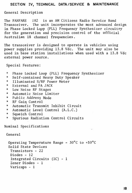
SECTION IV, TECHNICAL DATA /SERVICE & MAINTENANCE
General Description
The FANFARE 182 is an AM Citizens Radio Service Band Transceiver. The unit incorporates the most advanced design. in Phase Locked Lopp (PLL) Frequency Synthesizer circuitry for the generation and precision control of the official Australian 18 channel frequencies.
The transceiver is designed to operate in vehicles using power supplies providing 13.8 Vdc. The unit may also be used in base station installations when used with a 13.8 Vdc external power source.
Special Features:
• Phase Locked Loop (PLL) Frequency Synthesizer • Self-contained Heavy Duty Speaker • Illuminated S/RF Power Meter • External and PA JACK • Low Noise RF Stages • Automatic Noise Limiter • Public Address Mode • RF Gain Control • Automatic Transmit Inhibit Circuit • Automatic Level Control (A.L.C.) • Squelch Control • Spurious Radiation Control Circuits
Nominal Specifications
General
Operating Temperature Range - 30°C to +50°C Solid State Devices Transistors - 22 Diodes - 12 Integrated Circuits (IC) - Zener Diodes - 1 Varicaps - 1
18
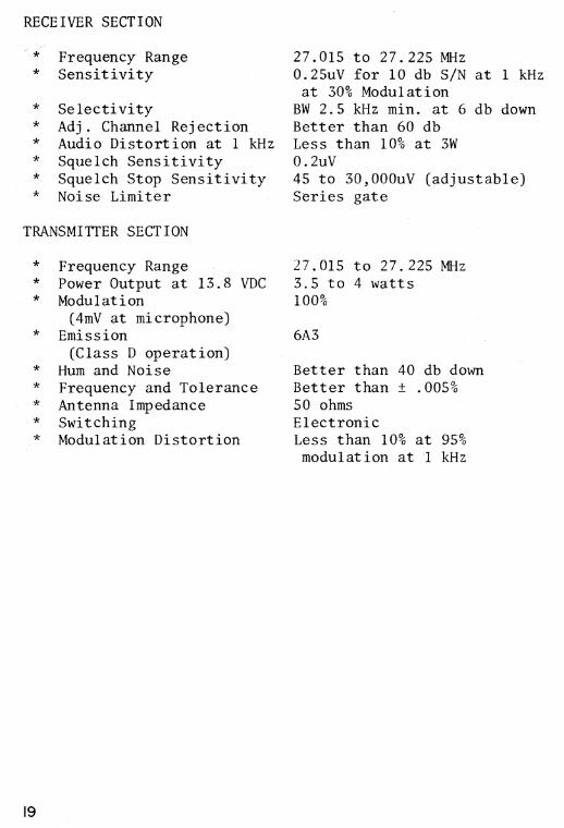
RECEIVER SECTION
* Frequency Range * Sensitivity
• Selectivity • Adj. Channel Rejection • Audio Distortion at 1 kHz • Squelch Sensitivity • Squelch Stop Sensitivity • Noise Limiter
TRANSMITTER SECTION
• Frequency Range • Power Output at 13.8 VDC • Modulation
(4mV at microphone) • Emission
(Class D operation) • Hum and Noise • Frequency and Tolerance • Antenna Impedance • Switching • Modulation Distortion
27.015 to 27.225 MHz 0.25uV for 10 db S/N at 1 kHz at 30% Modulation
BW 2.5 kHz min. at 6 db down Better than 60 db Less than 10% at 3W 0.2uV 45 to 30,000uV (adjustable) Series gate
27.015 to 27.225 MHz 3.5 to 4 watts 100%
6A3
Better than 40 db down Better than ± .005% 50 ohms Electronic Less than 10% at 95% modulation at 1 kHz
19
SERVICE AND MAINTENANCE
WARNING
THE POSTAL AND TELECOMMUNICATIONS DEPT. REQUIRES THAT ONLY PERSONS POSSESSING A VALID FIRST OR SECOND CLASS RADIOTELE-PHONE OPERATOR'S LICENSE ARE ALLOWED TO MAKE ADJUSTMENTS OR REPAIRS TO THE TRANSMITTING SECTION OF THIS TRANSCEIVER.
MODIFICATION TO THE TRANSMITTER SECTION IN ANY WAY NOT RECOM-MENDED BY THE IMPORTER OR TELECOM IS ILLEGAL. MODIFICA-TIONS INCLUDE, BUT ARE NOT LIMITED TO, SUBSTITUTION OF CRYSTALS, REPLACEMENT OF COMPONENT PARTS NOT OF THE SAME ELECTRICAL RATING, ADDITION OF ANY COMPONENT PART(S), CON-NECTIONS, DEVICE OR ACCESSORY INTERNALLY OR EXTERNALLY TO THE TRANSMITTER.
Troubleshooting assistance may be obtained by writing to Expo International Pty. Ltd. Address your in- quiry to the attention of the Customer Service Depart-ment. Always state the Model, Serial Number and Issue of Schematic Diagram to which the unit was built. The schematic issue letter may be found in the lower right hand corner of the schematic or from the legend on the printed circuit board.
When ordering parts, refer to the part number listed in the Replacement Parts List and give a description of the part. Mail to the attention of Parts Department.
WARRANTY OR OTHER SERVICE In the first instance your transceiver should be re-tuned to the Dealer from which it was purchased. In the event of difficult, service is availble directly from Expo International Pty. Ltd. 47-49 Buckley Street, Marrickville, N. S. W. 2204, Australia.
Transceiver should be carefully packed and post paid. Return packing and postage will be charged. Free Warranty Service is only available through your Dealers.
20
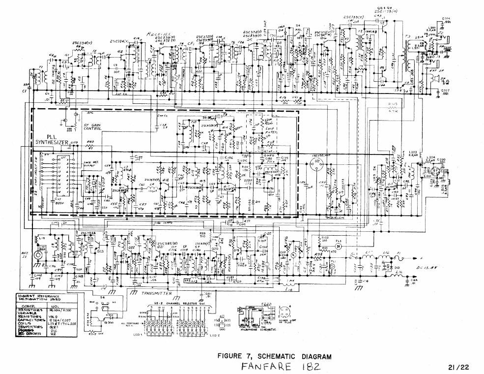
FIGURE 7, SCHEMATIC DIAGRAM
FANFARE 182 21/22
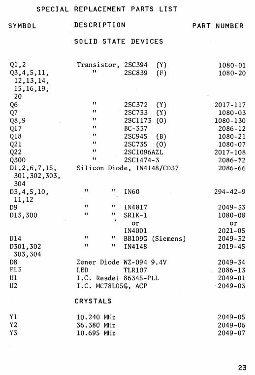
SPECIAL REPLACEMENT PARTS LIST
SYMBOL
DESCRIPTION
PART NUMBER
SOLID STATE DEVICES
Q1,2 Transistor, 2SC394 (Y) 1080-01 Q3,4,5,11, ii 2SC839 (F) 1080-20 12,13,14, 15,16,19, 20 Q6 ii 2SC372 (Y) 2017-117 Q7 ft 2SC733 (1) 1080-03 Q8,9 ii 2SC1173 (0) 1080-130 Q17 ii BC-337 2086-12 Q18 ii 2SC945 (B) 1080-21 Q21 ii 2SC735 (0) 1080-07 Q22 ii 2SC1096AZL 2017-108 Q300 " 2SC1474-3 2086-72 D1,2,6,7,15, Silicon Diode, IN4148/CD37 2086-66 301,302,303, 304 D3,4,5,10, if " IN60 294-42-9 11,12
D9 if ii IN4817 2049-33 D13,300 ii " SRIK-1 1080-08
or or IN4001 2021-05
D14 if If BB109G (Siemens) 2049-32 D301,302 ii " IN4148 2019-45 303,304 D8 Zener Diode WZ-094 9.4V 2049-34 PL3 LED TLR107 2086-13 Ul I.C. Resdel 86345-PLL 2049-01 U2 I.C. MC78L05, ACP '2049-03
CRYSTALS
Y1 10.240 MHz 2049-05 Y2 36.380 MHz 2049-06 Y3 10.695 MHz 2049-07
23
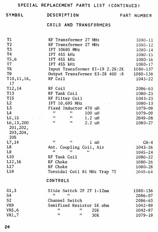
SPECIAL REPLACEMENT PARTS LIST (CONTINUED)
SYMBOL
DESCRIPTION PART NUMBER
COILS AND TRANSFORMERS
Ti RF Transformer 27 MHz 1080-11 T2 RF Transformer 27 MHz 1080-12 T3 IFT 10695 MHz 1080-14 T4 IFT 455 kHz 1080-15 T5,6 IFT 455 kHz 1080-16 T7 IFT 455 kHz 1080-17 T8 Input Transformer EI-19 2.2K:2K 1080-137 T9 Output Transformer EI-28 400 :8 1080-138 T10,11,16, RF Coil 1043-22
17 T12,14 RF Coil 2086-63 T13 RF Tank Coil 1080-23 T15 RF Filter Coil 1043-23 L2 IFT 10.695 MHz 1080-13 L3 Fixed Inductor 470 uH 1079-08 L4 ft tt 100 uH 1079-09 L5,15 It li 1.2 uH 2049-08 L6,13,200 II ft 2.2 uH 1080-27 201,202, 203,204, 205
L7,14 tt if 1 mH CH-4 L8 Ant. Coupling Coil, Air 1043-26 L9 ft ?I If 1045-24 L10 RF Tank Coil 1080-22 L12,16 RF Choke 1080-26 L17 RF Choke 1080-28 L19 Toroidal Coil 81 MHz Trap 7T 2049-64
CONTROLS
S1,3 Slide Switch 2F 2T 1-12mm 1080-136 S4 TI tt 2086-07 S2 Channel Switch 2086-63 VR9 Semifixed Resistor 5K ohm 1042-99 VR5,6 If ft 20K 1042-97 VR1,7 tt it 30K 1079-19
24
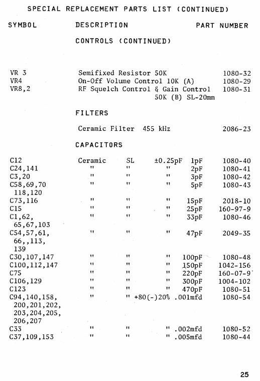
SPECIAL REPLACEMENT PARTS LIST ( CONTINUED)
SYMBOL
DESCRIPTION PART NUMBER
CONTROLS ( CONTINUED )
VR 3 Semifixed Resistor 50K 1080-32 VR4 On-Off Volume Control 10K (A) 1080-29 VR8,2 RF Squelch Control & Gain Control 1080-31
50K (B) SL-20mm
FILTERS
Ceramic Filter 455 kHz
2086-23
CAPACITORS
Ceramic tt
it
it
C12 C24,141 C3,20 C58,69,70 118,120
C73,116 C15 C1,62, 65,67,103 C54,57,61, 66„113, 139
C30,107,147 C100,112,147 C75 C106,129 C123 094,140,158, 200,201,202, 203,204,205, 206,207 C33 C37,109,153
SL
±0.25pF 1pF 1080-40 It
If 2pF 1080-41 If
3pF 1080-42 It
5pF 1080-43
tt 15pF 2018-10 tt 25pF 160-97-9
33pF 1080-46
47pF 2049-35
100pF 1080-48
150pF 1042-156
220pF 160-07-9*
300pF 1004-102
470pF 1080-51
+80(-)20% .001mfd 1080-54
" .002mfd 1080-52
" .005mfd 1080-44
It it
ft
it
25
LIMITED WARRANTY
TO VALIDATE WARRANTY CLAIM the original sales receipt must
accompany the product to the Service Centre.
EXPO INTERNATIONAL PTY. LTD. warrants each new electronic product
manufactured by it to be free from defective material and workmanship and
agrees to remedy any such defect or to furnish a new part (at the Company's
option) in exchange for any part of any unit of its manufacture which under
normal installation, use and service disclosed such defect; provided the unit is
delivered by the owner to us or to our authorized distributor from whom
purchased, or authorized service station, intact, for our examination, with all
transportation charges prepaid to our factory, within 90 days from the date of
sale to original purchaser and provided that such examination discloses, in our
judgment, that it is thus defective.
Written authorization must be obtained before any merchandise is returned
to the factory.
This warranty does not extend to any of our electronic products which have
been subjected to misuse, neglect, accident, incorrect wiring not our own,
improper installation, unauthorized modifications, or to use in violation of
instructions furnished by us, nor units which have been repaired or altered
outside of our factory, nor to cases where the serial number thereof has been
removed, defaced or changed.
This warranty is in lieu of all warranties expressed or implied and no
representative or person is authorized to assume for us any other liability in
connection with the sale of our electronic products.
EXPO INTERNATIONAL PTY. LTD. IMPORTERS — DISTRIBUTORS — MANUFACTURERS
47-49 BUCKLEY STREET, MARRICKVILLE, N.S.W., 2204, AUSTRALIA
N.S.W. EXPO International Pty Ltd — 47-49 Buckley St, Marrickville.
VICTORIA EXPO International Pty Ltd — 76 Victoria St, Nth Richmond.
QUEENSLAND General Wholesalers Pty Ltd — 33 Baxter St, Fortitude Valley.
WEST AUST. G.K. Cameron & Co. Pty Ltd — 246 Churchill Avenue, Subiaco.
STH AUST. Graham Noble Distributors — Cnr Benjamin & Kiana Sts, St Marys.