Embed Size (px)
Citation preview
FAN CONTROL AND INTEGRATEDFAN CONTROL AND INTEGRATEDFAN CONTROL AND INTEGRATED FAN CONTROL AND INTEGRATED ECONOMIZER TITLE 24 PROPOSALECONOMIZER TITLE 24 PROPOSAL
CARRIER COMMENTSCARRIER COMMENTS
10-30-2011Richard Lord
Carrier Corporation
IntroductionIntroduction• The following presentation is a summary of the analysis work that
Carrier Corporation has done regarding the Fan Control and Integrated Economizer Proposed changes to Title 24Economizer Proposed changes to Title 24
• The analysis was done to validate a similar proposal that has been proposed to ASHRAE 90.1 at the Oct 2011 interim meeting.
• The proposals are very similar and therefore the analysis should be applicable to the changes being proposed to Title 24
• Carrier has filled official comments on the proposal to Title 24 and this document provides backup details.
• We have updated the presentation to reflect additional comments• We have updated the presentation to reflect additional comments regarding the latest Title 24 justification document dated
2

Executive SummaryExecutive Summary• Overall the Carrier and industry do not support the proposal as currently written and this
has been communicated thru AHRI as well as Carrier comments
• The proposal should have been separated into two separate proposal so 2 speed fan and i t t d i ld b l t d it’ itintegrated economizer could be evaluated on it’s own merit.
• It is likely that the industry will support the fan speed proposal, but will not support the variable capacity as it is not economically justified.
It i l i d th t d t il bl b t th hi h ti d t d l• It is claimed that products are available but they are very high tier products and are only available in small sizes less than the capacity range of the proposal. This proposal is essentially specifies products that current do not exist and are not planned for production.
• The economizer integrated issues can be solved in a much more cost effective mannerThe economizer integrated issues can be solved in a much more cost effective manner using control logic and does not require modulating capacity control on constant volume and 2 speed units.
• We do agree that at a minimum 4 stages of capacity control should be required on VAV it b t th t l ill t fi i t t d i i d t l hunits, but that alone will not fix integrated economizer issues and controls changes are
also need.
• There has been very little discussion with the industry and AHRI, but the industry would be very willing to entering into discussion to arrive at a more practical proposal.be very willing to entering into discussion to arrive at a more practical proposal.
• This document includes an alternate proposal which we believe an industry consensus as well as a national implementation could be developed. 3
Integrated Economizer AnalysisIntegrated Economizer Analysis
4
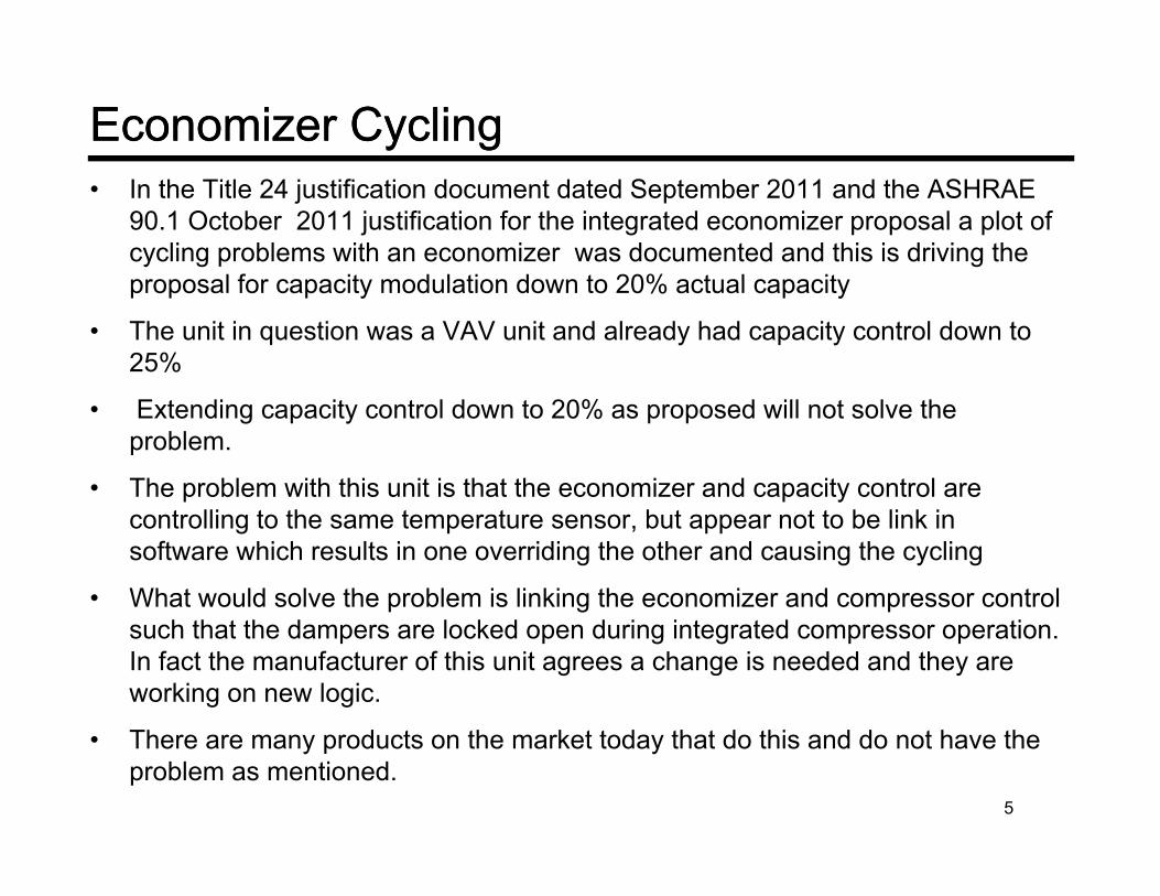
Economizer CyclingEconomizer Cycling• In the Title 24 justification document dated September 2011 and the ASHRAE
90.1 October 2011 justification for the integrated economizer proposal a plot of cycling problems with an economizer was documented and this is driving the
l f it d l ti d t 20% t l itproposal for capacity modulation down to 20% actual capacity
• The unit in question was a VAV unit and already had capacity control down to 25%
• Extending capacity control down to 20% as proposed will not solve the problem.
• The problem with this unit is that the economizer and capacity control are controlling to the same temperature sensor, but appear not to be link in software which results in one overriding the other and causing the cycling
• What would solve the problem is linking the economizer and compressor control such that the dampers are locked open during integrated compressor operation. In fact the manufacturer of this unit agrees a change is needed and they are working on new logic.
Th d t th k t t d th t d thi d d t h th• There are many products on the market today that do this and do not have the problem as mentioned.
5
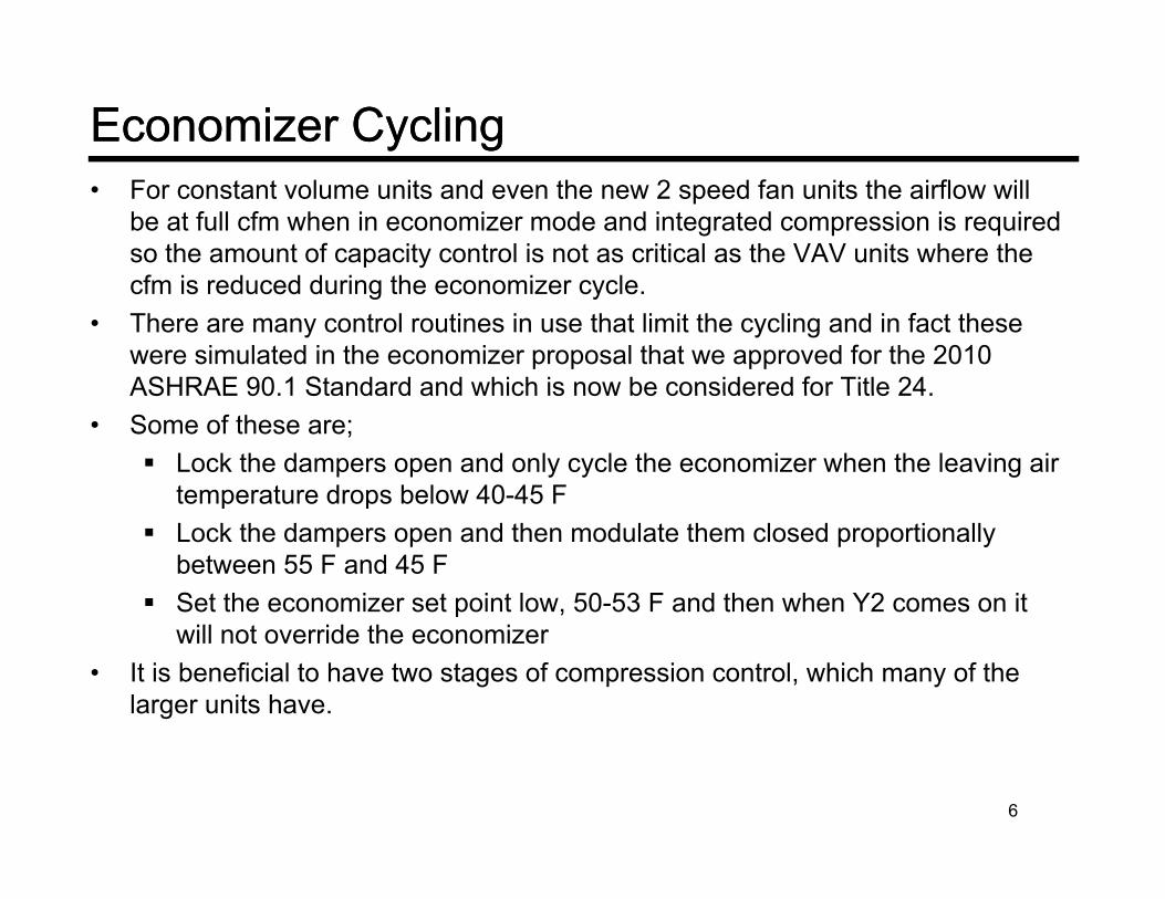
Economizer CyclingEconomizer Cycling• For constant volume units and even the new 2 speed fan units the airflow will
be at full cfm when in economizer mode and integrated compression is required so the amount of capacity control is not as critical as the VAV units where the f i d d d i th i lcfm is reduced during the economizer cycle.
• There are many control routines in use that limit the cycling and in fact these were simulated in the economizer proposal that we approved for the 2010 ASHRAE 90.1 Standard and which is now be considered for Title 24.ASHRAE 90.1 Standard and which is now be considered for Title 24.
• Some of these are; Lock the dampers open and only cycle the economizer when the leaving air
temperature drops below 40-45 Fp p Lock the dampers open and then modulate them closed proportionally
between 55 F and 45 F Set the economizer set point low, 50-53 F and then when Y2 comes on it
will not override the economizer• It is beneficial to have two stages of compression control, which many of the
larger units have.
6
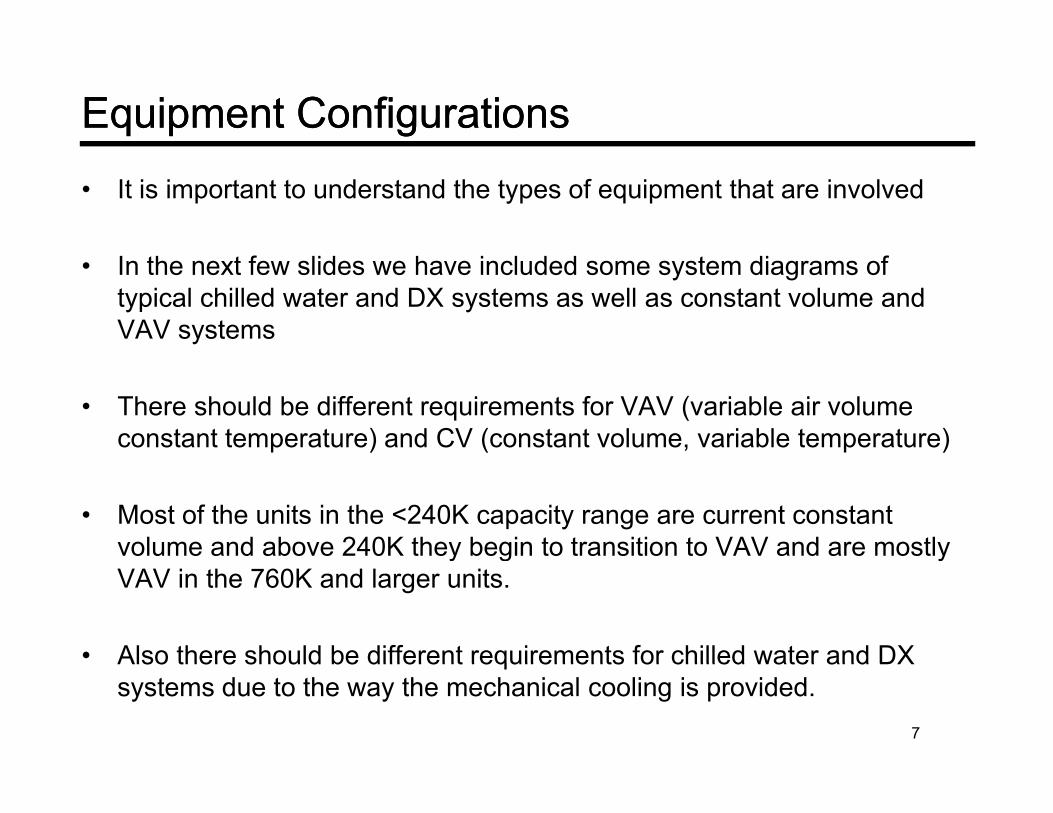
Equipment ConfigurationsEquipment Configurations• It is important to understand the types of equipment that are involved
• In the next few slides we have included some system diagrams of typical chilled water and DX systems as well as constant volume and VAV systems
• There should be different requirements for VAV (variable air volume constant temperature) and CV (constant volume, variable temperature)
• Most of the units in the <240K capacity range are current constant volume and above 240K they begin to transition to VAV and are mostly y g yVAV in the 760K and larger units.
• Also there should be different requirements for chilled water and DXAlso there should be different requirements for chilled water and DX systems due to the way the mechanical cooling is provided.
7

Background Background –– Equipment ConfigurationsEquipment ConfigurationsTypical Large VAV Chilled Water SystemTypical Large VAV Chilled Water System
Typically supply air set point is 55 F and i d f b h h i dis used for both the economizer and chilled water coil
ASHRAE 90.1 Supply Reset
Typical Reset
Supply air set point = 55 FSpace set point = 75 FMax Reset = .25 x (75-55) = 5 F
8
Max Reset Temperature = 60 FBecause the VAV system cfm is a function of the building load, I found that for the benchmark buildings the average maximum cfm during economizer operation is around 50% so the full benefit of economizers is not obtained. Reset which is required up to around 60 F helps.

Background Background –– Medium Packaged RooftopMedium Packaged Rooftop
For the large units many units use a 2 compressor design, but each compressor is in a separate circuit with a face split coil
Again they are mostly constantAgain they are mostly constant volume and are controlled directly by a thermostat.
Most of the units in the 65K to 110K capacity range are constant volume units. In fact most units up to around 240K are constant volume.
9
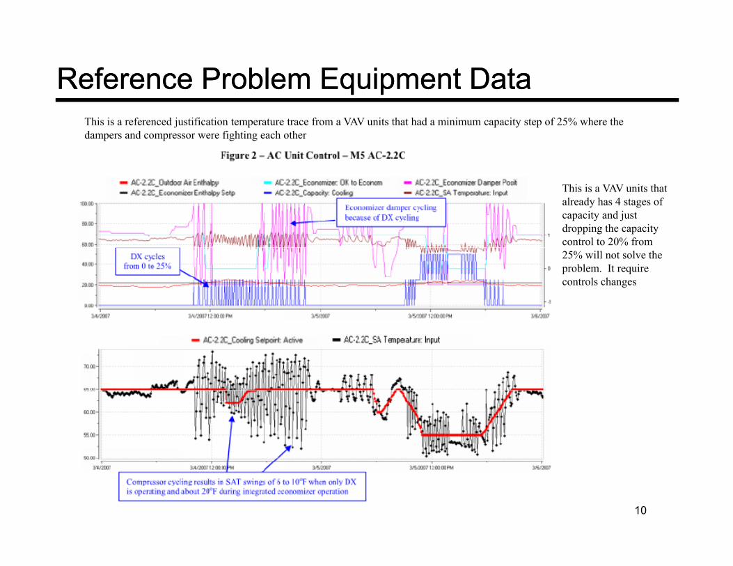
Reference Problem Equipment DataReference Problem Equipment DataThis is a referenced justification temperature trace from a VAV units that had a minimum capacity step of 25% where the dampers and compressor were fighting each other
This is a VAV units that already has 4 stages of capacity and just dropping the capacity control to 20% from 25% will not solve the problem. It require controls changes
10

Typical 5 Ton Single Stage RooftopTypical 5 Ton Single Stage Rooftop
3.5
4
95
105 5‐ton unit 50‐985‐97: 60 ambient, free cooling, Y1 & Y2, Comp cycled because of SAT
Low Cool SAT Setpoint = 65High Cool SAT Setpoint = 55
This is a trace from an actual Carrier 5 ton unit with a single compressor where the dampers are locked open and the
2
2.5
3
65
75
85
ECONOCMD
ECONOPOS
OA_TEMP
SAT Min High = 60SAT Min Low = 45
p pcompressor cycles on and off at duty cycle of around 10 minutes. There is degradation in performance due to the lower suctions and cycling but this was reflected in the original ASHRAE 90 1 economizer analysis
10 min
1
1.5
45
55
SAT_DISP
COMP_A
Y1
Y2
original ASHRAE 90.1 economizer analysis and is significantly less than the assume used for the Title 24 and ASHRAE justification which assume a 25% loss in all economizer operation
0
0.5
25
35
12:56:30
12:57:22
12:58:13
12:59:05
12:59:56
13:00:48
13:01:39
13:02:31
13:03:23
13:04:14
13:05:05
13:05:57
13:06:47
13:07:40
13:08:31
13:09:22
13:10:14
13:11:06
13:11:57
13:12:49
13:13:41
13:14:32
13:15:24
13:16:16
13:17:08
13:18:00
13:18:53
13:19:44
13:20:37
13:21:29
13:22:21
13:23:13
13:24:06
13:24:58
13:25:50
13:26:43
13:27:34
13:28:27
13:29:19
13:30:11
13:31:04
13:31:56
Addition of two stages of capacity will further improve this and many of the units already have two mechanical stages
This the worst case with a single compressor but it shows with proper controls that the full benefit of
11
the economizer is ob tained

Integrated Economizer ExampleIntegrated Economizer ExampleThe following shows the building load profile for the 5,400 ft2 office building in San Francisco which is a high economizer use climate zone. Highlighted are the operating hours where economizer only can satisfy the load, economizer plus compressors are used (integration) and compressor only
E i l O tiIntegrated EconomizerC E iEconomizer only Operation
1880 hrsComp + Economizer
758 hrs
e
Mechanical CoolingNo Economizer
12
535 hrs
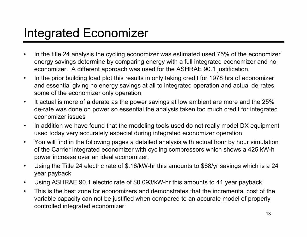
Integrated EconomizerIntegrated Economizer• In the title 24 analysis the cycling economizer was estimated used 75% of the economizer
energy savings determine by comparing energy with a full integrated economizer and no economizer. A different approach was used for the ASHRAE 90.1 justification.
• In the prior building load plot this results in only taking credit for 1978 hrs of economizer and essential giving no energy savings at all to integrated operation and actual de-rates some of the economizer only operation.
• It actual is more of a derate as the power savings at low ambient are more and the 25%It actual is more of a derate as the power savings at low ambient are more and the 25% de-rate was done on power so essential the analysis taken too much credit for integrated economizer issues
• In addition we have found that the modeling tools used do not really model DX equipment used today very accurately especial during integrated economizer operationused today very accurately especial during integrated economizer operation
• You will find in the following pages a detailed analysis with actual hour by hour simulation of the Carrier integrated economizer with cycling compressors which shows a 425 kW-h power increase over an ideal economizer.
f $ / $ /• Using the Title 24 electric rate of $.16/kW-hr this amounts to $68/yr savings which is a 24 year payback
• Using ASHRAE 90.1 electric rate of $0.093/kW-hr this amounts to 41 year payback.• This is the best zone for economizers and demonstrates that the incremental cost of the s s e bes o e o eco o e s a d de o s a es a e c e e a cos o e
variable capacity can not be justified when compared to an accurate model of properly controlled integrated economizer
13
Study Proposal Assumptions & ClaimsStudy Proposal Assumptions & ClaimsIntegrated Economizers
• The proposal justifications claims that the addendum CY economizer proposal d f ll i t t d iassumed full integrated economizers.
• This is not correct and the economizers were de-rated when the supply air temperature went below 55 F which is a conservative estimate.
• For the CMP analysis is was assumed that the integrated cycle would result in the loss of all integrated economizer energy savings which is grossly overstated
14

Conclusions for Integrated EconomizersConclusions for Integrated Economizers• Using modulating compressors on constant volume is not necessary
and will be a very expensive option compared to controls based solutions that are essentially very low to no cost optionssolutions that are essentially very low to no cost options.
• Modulating capacity down to 25% or even lower on VAV units is important and in fact should be lower but controls requirements are stillimportant and in fact should be lower, but controls requirements are still needed to interlock the compressors and economizers
• We believe that a single compressor with an economizer is not ideal• We believe that a single compressor with an economizer is not ideal and would recommend to improve economizer integration that 2 compressor stages are used along with requirements on controls similar to what is required in ASHRAE 189.1to what is required in ASHRAE 189.1
• The proposal also poor approach and should not define how equipment is design but should define performance requirementsis design, but should define performance requirements.
15

MODULATING COMPRESSOR MODULATING COMPRESSOR CAPACITY CONTROLCAPACITY CONTROL
16
Modulating Compressor CapacityModulating Compressor Capacity• Many claims were made throughout the Title 24 justification and
ASHRAE 90.1 justification that are not correct.
• Modulating compressors are starting to be used and they have some advantages for temperature control, especially on VAV systems, but they are expensive, are often noisy at part load and do not get to the 20% iti i d b th l20% capacities required by the proposal.
• Equal benefits can be obtained with multiple compressors and advanced controls which are being used on many products in the market today with much lower applied costs.
• In the following pages you will find some of the issues we found with the claims made in the justificationc a s ade t e just cat o
17
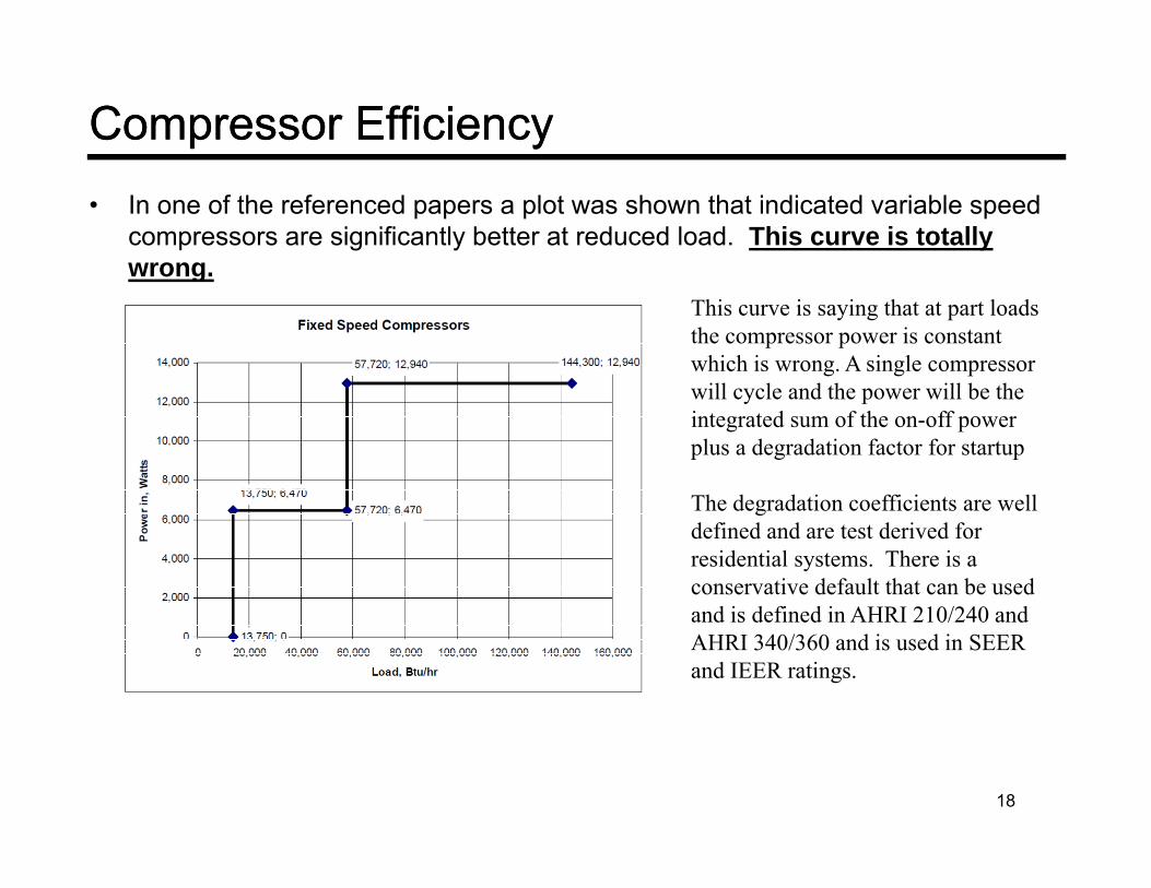
Compressor EfficiencyCompressor Efficiency• In one of the referenced papers a plot was shown that indicated variable speed
compressors are significantly better at reduced load. This curve is totally wrong.wrong.
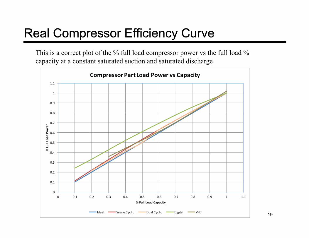
This curve is saying that at part loads the compressor power is constant which is wrong. A single compressor
ill le d the e ill be thewill cycle and the power will be the integrated sum of the on-off power plus a degradation factor for startup
The degradation coefficients are wellThe degradation coefficients are well defined and are test derived for residential systems. There is a conservative default that can be used and is defined in AHRI 210/240 andand is defined in AHRI 210/240 and AHRI 340/360 and is used in SEER and IEER ratings.
18
Real Compressor Efficiency CurveReal Compressor Efficiency Curve
Compressor PartLoad Power vs Capacity
This is a correct plot of the % full load compressor power vs the full load % capacity at a constant saturated suction and saturated discharge
0.9
1
1.1
Compressor Part Load Power vs Capacity
0.6
0.7
0.8
0.9
Power
0.3
0.4
0.5
% Fu
ll Load
0
0.1
0.2
19
0 0.1 0.2 0.3 0.4 0.5 0.6 0.7 0.8 0.9 1 1.1% Full Load Capacity
Ideal Single Cyclic Dual Cyclic Digital VFD

Alternate Compressor PlotAlternate Compressor Plot• The prior plot is misleading as it is only a compressor plot and does not factor in the rebalance of the
heat exchangers as they unload in a real system.• I created a plot of various compressor options to show what a real system impact would be.
f f f• This is a plot of compressor and condenser fan power at a fixed ambient and return air condition
The huge performance improvement is not there and dual compressors on a single circuit perform better than a digital and
Compressor and Condenser Fan Part Load Power vs Capacity with system rebalance at constant ambient
close to that of a full variable speed with much lower complexity
This is actual confirmed in that most who use the digital have to limit the capacity0 7
0.8
0.9
1
1.1
r use the digital have to limit the capacity unloading to get a good SEER
Also note that the variable speed can only get done to 30% and the requirements is
hi h i lik di l0.3
0.4
0.5
0.6
0.7
% Fu
ll Load
Pow
er
20% which is more like 15% displacement which would require dual compressors.
Costs provide to Title 24 analysis were based on single compressor digital
0
0.1
0.2
0 0.1 0.2 0.3 0.4 0.5 0.6 0.7 0.8 0.9 1 1.1
% Full Load Capacity
20
g p gDual Cylic Digital Inverter
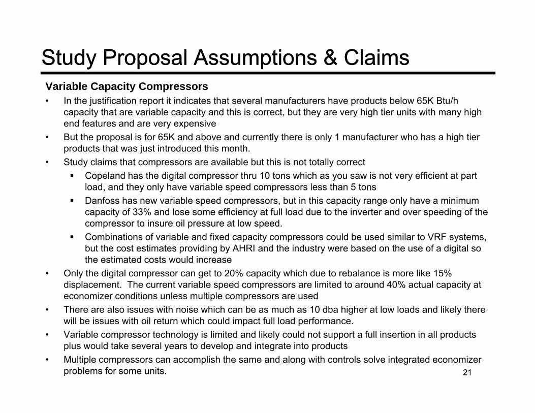
Study Proposal Assumptions & ClaimsStudy Proposal Assumptions & ClaimsVariable Capacity Compressors• In the justification report it indicates that several manufacturers have products below 65K Btu/h
capacity that are variable capacity and this is correct, but they are very high tier units with many high end features and are very expensivey
• But the proposal is for 65K and above and currently there is only 1 manufacturer who has a high tier products that was just introduced this month.
• Study claims that compressors are available but this is not totally correct Copeland has the digital compressor thru 10 tons which as you saw is not very efficient at part p g p y y p
load, and they only have variable speed compressors less than 5 tons Danfoss has new variable speed compressors, but in this capacity range only have a minimum
capacity of 33% and lose some efficiency at full load due to the inverter and over speeding of the compressor to insure oil pressure at low speed.
Combinations of variable and fixed capacity compressors could be used similar to VRF systems, but the cost estimates providing by AHRI and the industry were based on the use of a digital so the estimated costs would increase
• Only the digital compressor can get to 20% capacity which due to rebalance is more like 15% displacement The current variable speed compressors are limited to around 40% actual capacity atdisplacement. The current variable speed compressors are limited to around 40% actual capacity at economizer conditions unless multiple compressors are used
• There are also issues with noise which can be as much as 10 dba higher at low loads and likely there will be issues with oil return which could impact full load performance.
• Variable compressor technology is limited and likely could not support a full insertion in all productsVariable compressor technology is limited and likely could not support a full insertion in all products plus would take several years to develop and integrate into products
• Multiple compressors can accomplish the same and along with controls solve integrated economizer problems for some units. 21

Study Proposal Assumptions & ClaimsStudy Proposal Assumptions & ClaimsHumidity Control• Study claims that better humidity control will be obtained with the variable capacity and
variable speed fans.Variable speed fans will help part load humidity control during non integrated low load• Variable speed fans will help part load humidity control during non-integrated low load operation, but during economizer operation the fan is at high speed to get full benefit of the economizer
• The variable capacity compressor will actual decrease humidity control for contant volume variable temperature systems as shown in the plot of operation at economizer integrated conditions
Rooftop Latent Capacity75 F OAT, 70 F RAT, 70% RH
0.9
1
1.1
actor
Due to the rebalance of the heat exchangers the saturated suction rises and the latent capability of the DX coils at a constant CFM decreases and
0 5
0.6
0.7
0.8
Sensible Heat F
a at a constant CFM decreases and below about 30% capacity the coils is only providing sensible cooling
22
0.4
0.5
0 0.2 0.4 0.6 0.8 1 1.2Full Load Capacity Ratio (relative to AHRI rating point)
2 Speed Fan Control2 Speed Fan Control
23
2 Speed Fan Control2 Speed Fan Control• This was the original objective of the change proposal as discussed
with the AHRI ULE Section.
• It is an extension of the change proposal that goes into effect on 1/1/2012 for Title 24 and ASHRAE 90.1 that requires 2 speed fans on DX units greater than 110K Btu/h and chilled water systems with a fan HP greater than 5 HP
• In general this is a very good energy savings idea and is supported by Carrier and the industryCarrier and the industry
• We do have some issues with some of the analysis for ASHRAE 90.1 and Title 24, but in the end we found our analysis actual shows more savings.
24

Study Proposal Assumptions & ClaimsStudy Proposal Assumptions & ClaimsFan Speed Control – ASHRAE 90.1• The proposal requires for DX products a fan speed of 66% below a load of 50%• For ASHRAE 901. The justification document assumed Variable speed fans starting at
100% load down to a speed of 50% at 50% load100% load down to a speed of 50% at 50% load• This would indicate the savings might be overstated, but the proposal also assumed very
high fan and motor efficiencies and reduced the savings. In our analysis we actual found the savings are greater
Justification Fan Speed
Proposal Fan Speed
25
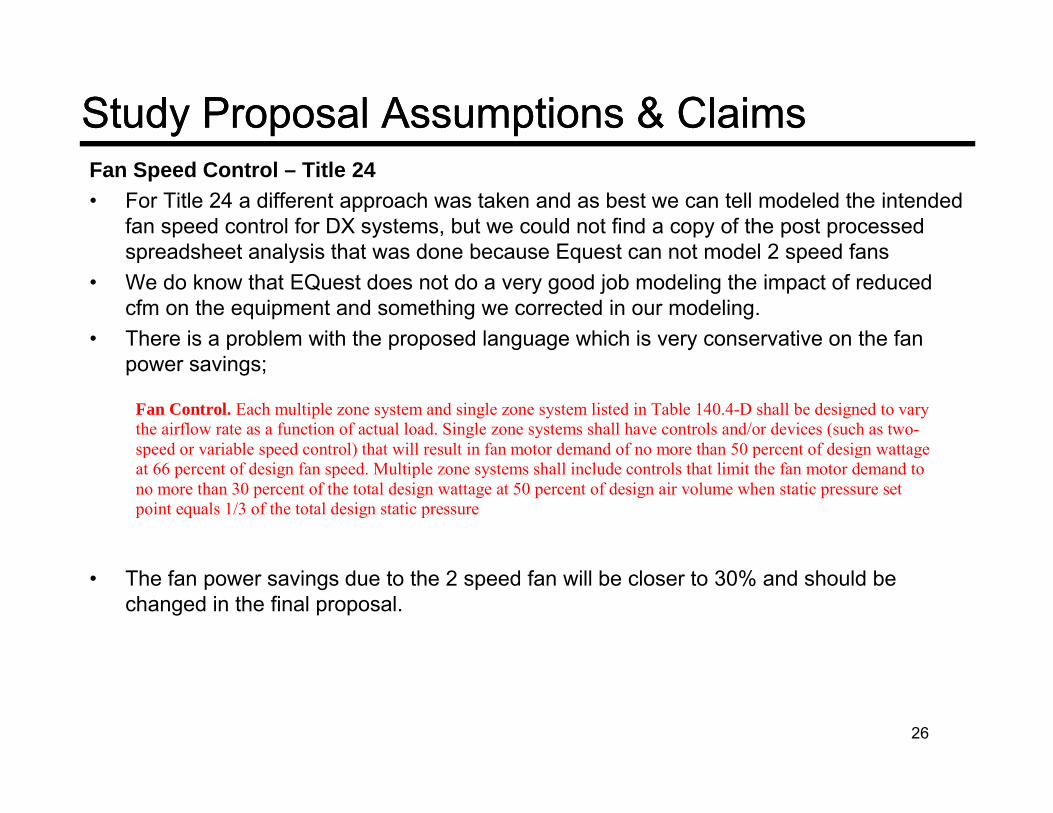
Study Proposal Assumptions & ClaimsStudy Proposal Assumptions & ClaimsFan Speed Control – Title 24• For Title 24 a different approach was taken and as best we can tell modeled the intended
fan speed control for DX systems, but we could not find a copy of the post processed spreadsheet analysis that was done because Equest can not model 2 speed fansspreadsheet analysis that was done because Equest can not model 2 speed fans
• We do know that EQuest does not do a very good job modeling the impact of reduced cfm on the equipment and something we corrected in our modeling.
• There is a problem with the proposed language which is very conservative on the fan power savings;
Fan Control. Each multiple zone system and single zone system listed in Table 140.4-D shall be designed to vary the airflow rate as a function of actual load. Single zone systems shall have controls and/or devices (such as two-speed or variable speed control) that will result in fan motor demand of no more than 50 percent of design wattage p p ) p g gat 66 percent of design fan speed. Multiple zone systems shall include controls that limit the fan motor demand to no more than 30 percent of the total design wattage at 50 percent of design air volume when static pressure set point equals 1/3 of the total design static pressure
• The fan power savings due to the 2 speed fan will be closer to 30% and should be changed in the final proposal.
26
ENERGY ANALYSISENERGY ANALYSIS
27

Study Proposal Assumptions & ClaimsStudy Proposal Assumptions & Claims• Energy Analysis
The ASHRAE 90.1 study only looked at zones 2a, 2b, 3a, 4a, 5a, 5b and did not always use the ASHRAE standard work benchmark cities
For the ASHRAE 90.1 analysis it assumed a complete loss of all integrated economizer benefitsFor the ASHRAE 90.1 analysis it assumed a complete loss of all integrated economizer benefits by using 60 F dry bulb changeover as the base and differential drybulb for the proposal
For Title 24 it assumed a 25% de-rate in all economizer benefits Differential drybulb was used in a zones but is not allowed in current 90.1 high limits and in the
proposal Taylor CMPp p y Study used a product with a 9.7 SEER which is far below the current 90.1 requirement of 13
SEER. Also the SEER rated model likely was for a single stage product below 65 KBtu/hr capacity and
the proposal is for products >65K It was likely the default model for the DX product was used which is a residential single stage
products and it does not properly model variable capacity or even 2 stage capacity We have also found that DOE2 models do not really model performance at low return air
temperatures seen during integrated economizer operation. ASHRAE 90.1 unit was modeled as a VAV that throttles down to 50% fan speed which is not the
proposal, but is a limit of Equest, DOE2 and EnergyPlus Model was based on 2.5 inch total static which is about 1.3 inch external which is the high end of
the application range for these products. Some units are applied down at more like .5 inches for concentric ducts AHRI rating static is 0 35 to 0 40 inch external static This makes the benefitsconcentric ducts. AHRI rating static is 0.35 to 0.40 inch external static. This makes the benefits of variable speed higher. A sensitive study would have been a good idea.
28
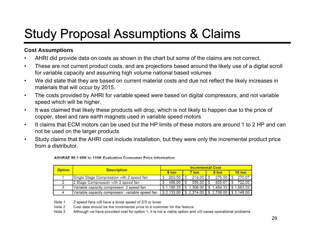
Study Proposal Assumptions & ClaimsStudy Proposal Assumptions & ClaimsCost Assumptions• AHRI did provide data on costs as shown in the chart but some of the claims are not correct.• These are not current product costs, and are projections based around the likely use of a digital scroll
for variable capacity and assuming high volume national based volumesp y g g• We did state that they are based on current material costs and due not reflect the likely increases in
materials that will occur by 2015.• The costs provided by AHRI for variable speed were based on digital compressors, and not variable
speed which will be higher.• It was claimed that likely these products will drop, which is not likely to happen due to the price of
copper, steel and rare earth magnets used in variable speed motors• It claims that ECM motors can be used but the HP limits of these motors are around 1 to 2 HP and can
not be used on the larger products• Study claims that the AHRI cost include installation, but they were only the incremental product price
from a distributor.
29

Energy AnalysisEnergy Analysis• There are many issues with trying to model this in DOE2, EQuest or EnergyPlus as noted
in the justification report• We have also found that the current modeling methods used in the building simulation
d t l d l i bl it d i bl f d t dprograms do not properly model variable capacity and variable cfm products and are primarily based on full load single stage DX units that cycle at part load (Old Style Residential Equipment)
• To analysis this we created an expanded model of a typical 6 ton unit that meets the 2010 Efficiency requirements for EER and IEER. The product has an 11.0 EER and 11.2 IEER at AHRI rating conditions
• We used the building model output from the EnergyPlus models for the 5,400 ft2 small office for the 2004 ASHRAE code and then normalized it allow for analysis of the 6 ton yunit. This is the same model used for the Title 24 and ASHRAE 90.1 studies.
• This was then post processed thru a large spreadsheet tool with Visual Basic models of the compressors, economizers and models of the psychometric properties
• This allows us to look at the details of the operation at each hour of operation• This allows us to look at the details of the operation at each hour of operation• We including models to simulation lower leaving air temperatures during integrated
economizer operation which correctly analyzed integrated economizer operation.• Cyclic performance was degraded using the default cyclic coefficients from the
AHRI340/360 standard which we know are conservative. When we test for them they are typically better
30
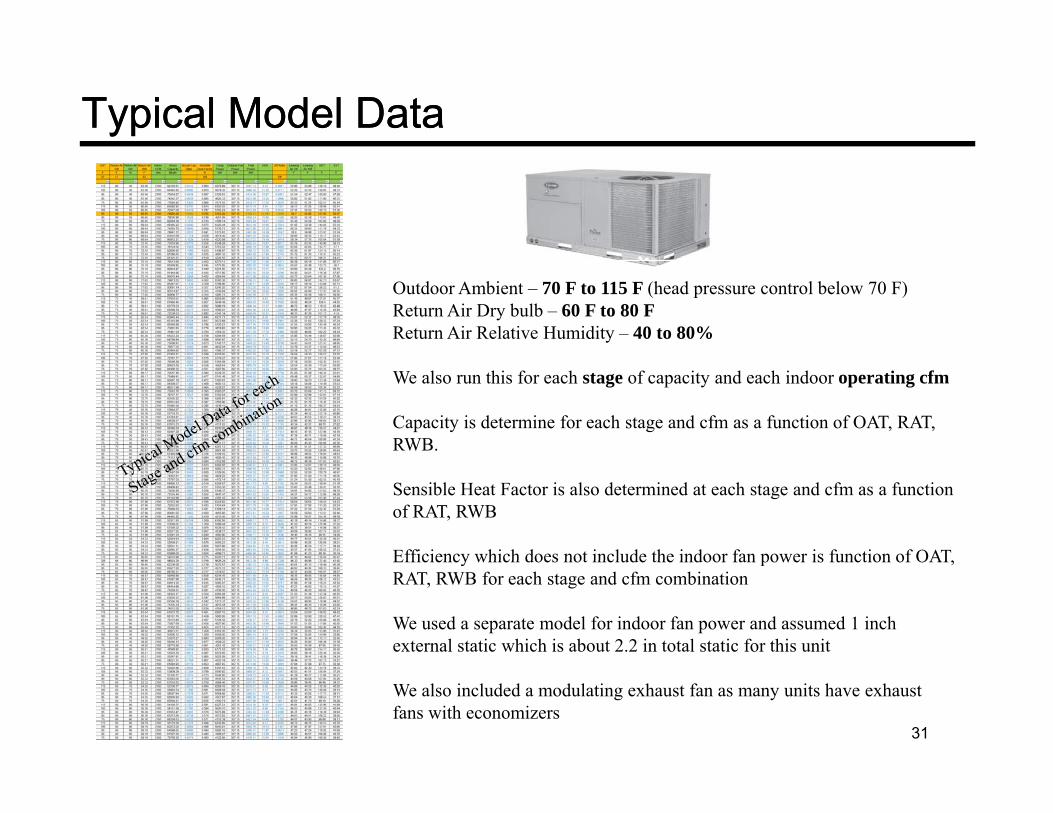
Typical Model DataTypical Model Data
Outdoor Ambient – 70 F to 115 F (head pressure control below 70 F)Return Air Dry bulb – 60 F to 80 FReturn Air Relative Humidity – 40 to 80%
We also run this for each stage of capacity and each indoor operating cfm
Capacity is determine for each stage and cfm as a function of OAT, RAT, RWB.
Sensible Heat Factor is also determined at each stage and cfm as a function of RAT, RWB
Efficiency which does not include the indoor fan power is function of OAT,Efficiency which does not include the indoor fan power is function of OAT, RAT, RWB for each stage and cfm combination
We used a separate model for indoor fan power and assumed 1 inch external static which is about 2.2 in total static for this unit
31
We also included a modulating exhaust fan as many units have exhaust fans with economizers
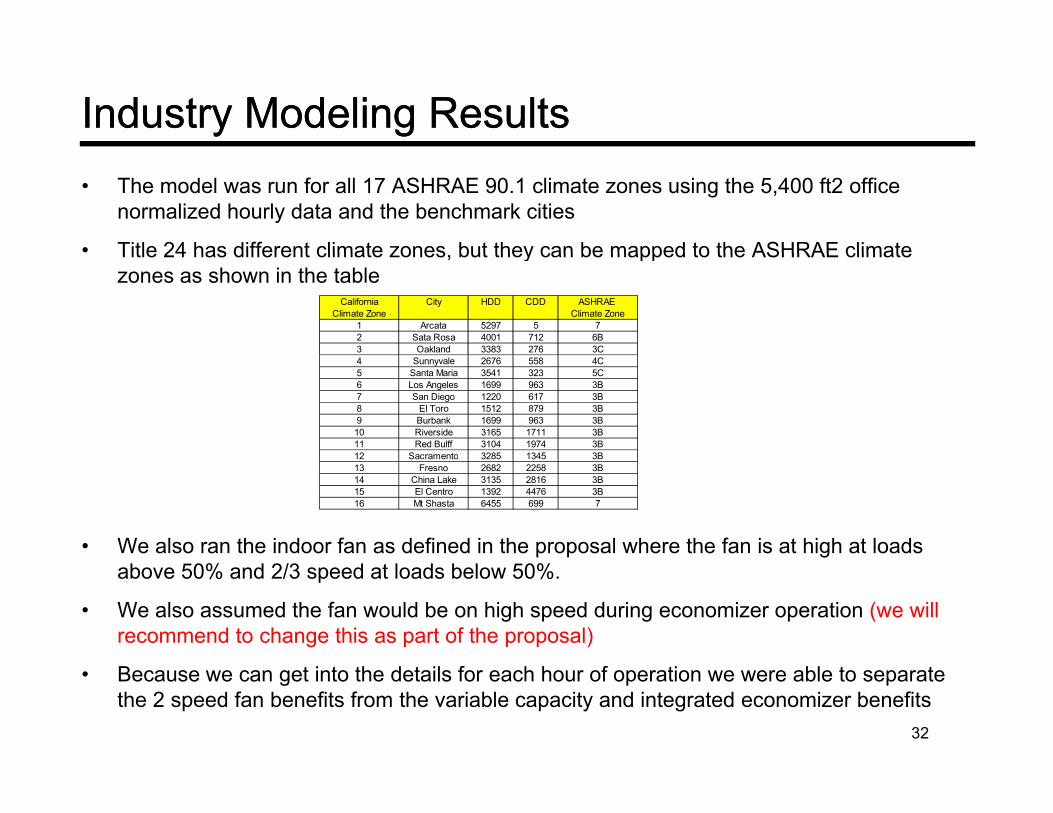
Industry Modeling ResultsIndustry Modeling Results• The model was run for all 17 ASHRAE 90.1 climate zones using the 5,400 ft2 office
normalized hourly data and the benchmark cities
• Title 24 has different climate zones but they can be mapped to the ASHRAE climateTitle 24 has different climate zones, but they can be mapped to the ASHRAE climate zones as shown in the table
California City HDD CDD ASHRAE Climate Zone Climate Zone
1 Arcata 5297 5 72 Sata Rosa 4001 712 6B3 Oakland 3383 276 3C4 Sunnyvale 2676 558 4C5 Santa Maria 3541 323 5C6 Los Angeles 1699 963 3B7 San Diego 1220 617 3B8 El Toro 1512 879 3B9 Burbank 1699 963 3B10 Riverside 3165 1711 3B11 Red Bulff 3104 1974 3B12 Sacramento 3285 1345 3B
• We also ran the indoor fan as defined in the proposal where the fan is at high at loads
12 Sacramento 3285 1345 3B13 Fresno 2682 2258 3B14 China Lake 3135 2816 3B15 El Centro 1392 4476 3B16 Mt Shasta 6455 699 7
above 50% and 2/3 speed at loads below 50%.
• We also assumed the fan would be on high speed during economizer operation (we will recommend to change this as part of the proposal)
• Because we can get into the details for each hour of operation we were able to separate the 2 speed fan benefits from the variable capacity and integrated economizer benefits
32

Integrated Economizer AnalysisIntegrated Economizer Analysis• In the CMP proposal the variable capacity and variable fan change benefits were lumped together and
the full derate of the economizer was taken between integrated and non integrated• Using the model that Carrier developed, we separated out the integrated economizer savings result
from the variable capacity compressorfrom the variable capacity compressor• The justification document simulated the integrated economizer benefits by comparing full integrated
savings vs non integrated savings which overstates the semi-integrated operation.
Economizer Integrated hrs<55 F Economizer Integrated hrs<55 F Non-Ideal Non-Ideal Incremental Payback Scalar Justified60 F Drybulb Changeover Taylor Drybulb ChangeoverZone CITY
LAT LAT Incremental Power
Incremental Power Cost
First Cost Limit
hrs hrs hrs hrs hrs hrs kW-h $ $ yrs yrs1A Miami 92 0 0 332 53 53 4 0.36 1637 4491.5 8.86 No1B Riyadh 356 0 0 1039 307 86 6 0.58 1637 2801.6 8.86 No2A Houston 390 0 0 774 56 56 2 0.21 1637 7918.6 8.86 No2B Phoenix 495 0 0 1212 290 64 3 0.31 1637 5294.1 8.86 No3A Memphis 651 0 0 1134 106 106 8 0.76 1637 2146.8 8.86 No3B El Paso 907 0 0 1660 345 108 26 2.41 1637 680.4 8.86 No3C San Francisco 1413 0 0 2638 758 591 425 39.94 1637 41.0 8.86 No4A Baltimore 760 0 0 1194 131 131 18 1.66 1637 983.4 8.86 No4B Albuquerque 1259 0 0 1943 362 155 47 4.43 1637 369.5 8.86 No4C Salem 959 0 0 1652 404 273 102 9.55 1637 171.3 8.86 No5A Chicago 627 0 0 1001 109 109 20 1.92 1637 853.4 8.86 No5B Boise 1087 0 0 1622 345 192 42 3.97 1637 411.8 8.86 No5C Vancouver 1123 20 20 1811 525 491 1052 98.82 1637 16.6 8.86 No
Non-Integrated Base Case Semi-Integrated Results
5C Vancouver 1123 20 20 1811 525 491 1052 98.82 1637 16.6 8.86 No6A Burlington 693 0 0 1273 331 329 132 12.37 1637 132.4 8.86 No6B Helena 1060 0 0 1683 417 198 86 8.06 1637 203.0 8.86 No7 Duluth 1006 0 0 1460 252 210 112 10.56 1637 155.0 8.86 No8 Fairbanks 953 18 18 1390 379 272 314 29.46 1637 55.6 8.86 No
33
As you can see the Variable capacity change by itself does not meet the Scalar limit for a 15 year design life. For Title 24 the payback period will be 58% of the ASHRAE 90.1 numbers due to the higher electric rate but even in San Francisco the payback is still 23 years which is not cost effective.
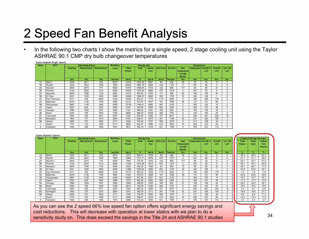
2 Speed Fan Benefit Analysis2 Speed Fan Benefit Analysis• In the following two charts I show the metrics for a single speed, 2 stage cooling unit using the Taylor
ASHRAE 90.1 CMP dry bulb changeover temperaturesTaylor Drybulb Single Speed
Cooling Mechanical Economizer Total Power
Cost Indoor Fan
Exh Fan Ton-hrs Non Integrated
hrs>28
Integrated hrs<55 F LAT
hrs<50 LAT
hrs <45 LAT
EconomizerZone CITY Operating hours Building Load
Energy Use
hrs 28 Btu/lb
hrs hrs hrs ton-hrs kw-h $ kw-h kw-h Ton-hrs hrs hrs hrs hrs hrs 1A Miami 3226 2911 332 8675 14734 1383.49 6991 86 298 36 53 53 13 01B Riyadh 3434 2543 1039 7850 20300 1906.16 9845 476 1157 2 307 86 0 02A Houston 2834 2074 774 6028 11670 1095.84 6142 122 609 117 56 56 21 02B Phoenix 3134 2053 1212 6046 16394 1539.36 8985 479 1219 2 291 65 0 03A Memphis 2654 1556 1134 4853 10170 954.92 5752 171 938 60 106 106 40 03B El Paso 3031 1549 1660 5409 14548 1366.07 8690 550 1763 22 345 108 1 03C San Francisco 2711 535 2638 3144 10354 972.27 7773 1113 3225 0 762 595 179 04A Baltimore 2278 1136 1194 3693 8178 767.87 4937 181 1008 39 131 131 66 14B Albuquerque 2881 1138 1943 4456 12739 1196 21 8260 547 2142 2 362 155 14 04B Albuquerque 2881 1138 1943 4456 12739 1196.21 8260 547 2142 2 362 155 14 04C Salem 2023 604 1652 2665 8197 769.66 5800 609 1904 2 405 274 89 05A Chicago 1980 1028 1001 3260 7127 669.22 4291 160 852 27 109 109 44 15B Boise 2235 794 1622 3180 9565 898.20 6408 484 1791 0 345 192 25 05C Vancouver 1881 345 1811 2574 7224 678.30 5393 747 2477 6 525 491 229 126A Burlington 1834 737 1273 2604 6181 580.41 3975 351 1139 32 331 329 136 36B Helena 2008 575 1683 2717 8328 782.00 5757 596 1879 0 417 198 46 07 Duluth 1737 412 1460 2117 6629 622.47 4980 419 1803 15 252 210 62 08 Fairbanks 1444 296 1390 1973 5631 528.79 4140 531 1785 0 379 272 113 7
T l D b lb 2 dTaylor Drybulb 2 speed
Cooling Mechanical Economizer Total Power
Cost Indoor Fan
Exh Fan Ton-hrs Non Integrated
hrs>28 Btu/lb
Integrated hrs<55 F LAT
hrs<50 LAT
hrs <45 LAT
Total Power
Total Cost
Indoor Fan
Power
hrs hrs hrs ton-hrs kw-h $ kw-h kw-h Ton-hrs hrs hrs hrs hrs hrs % % %1A Miami 3226 2911 332 8675 9374 880.22 2538 86 298 36 53 53 13 0 -36.4 -36.4 -63.71B Riyadh 3434 2543 1039 7850 13984 1313.11 4970 476 1157 2 307 86 0 0 -31.1 -31.1 -49.52A Houston 2834 2074 774 6028 7849 737.00 2972 122 609 117 56 56 21 0 -32.7 -32.7 -51.62B Phoenix 3134 2053 1212 6046 11454 1075.48 5073 479 1219 2 291 65 0 0 -30.1 -30.1 -43.5
Zone CITY Operating hours Building Load
Energy Use Economizer 2 Speed Energy Savings
3A Memphis 2654 1540 1134 4853 5425 509.38 1668 29 480 70 69 69 25 0 -46.7 -46.7 -71.03B El Paso 3031 1549 1660 5409 11065 1039.02 5899 550 1763 22 345 108 1 0 -23.9 -23.9 -32.13C San Francisco 2711 535 2638 3144 10173 955.23 7624 1113 3225 0 762 595 179 0 -1.8 -1.8 -1.94A Baltimore 2278 1136 1194 3693 6163 578.72 3269 181 1008 39 131 131 66 1 -24.6 -24.6 -33.84B Albuquerque 2881 1138 1943 4456 10363 973.06 6351 547 2142 2 362 155 14 0 -18.7 -18.7 -23.14C Salem 2023 604 1652 2665 7276 683.26 5045 609 1904 2 405 274 89 0 -11.2 -11.2 -13.05A Chicago 1980 1028 1001 3260 5309 498.55 2785 160 852 27 109 109 44 1 -25.5 -25.5 -35.15B Boise 2235 794 1622 3180 8015 752.58 5160 484 1791 0 345 192 25 0 -16.2 -16.2 -19.55C Vancouver 1881 345 1811 2574 7053 662.32 5250 747 2477 6 525 491 229 12 -2.4 -2.4 -2.66A Burlington 1834 737 1273 2604 5141 482.78 3111 351 1139 32 331 329 136 3 -16.8 -16.8 -21.76B Helena 2008 575 1683 2717 7508 705.02 5095 596 1879 0 417 198 46 0 -9.8 -9.8 -11.5
34
6B Helena 2008 575 1683 2717 7508 705.02 5095 596 1879 0 417 198 46 0 9.8 9.8 11.57 Duluth 1737 412 1460 2117 5949 558.61 4416 419 1803 15 252 210 62 0 -10.3 -10.3 -11.38 Fairbanks 1444 296 1390 1973 5498 516.23 4030 531 1785 0 379 272 113 7 -2.4 -2.4 -2.7
As you can see the 2 speed 66% low speed fan option offers significant energy savings and cost reductions. This will decrease with operation at lower statics with we plan to do a sensitivity study on. This does exceed the savings in the Title 24 and ASHRAE 90.1 studies

2 Speed Economic Analysis2 Speed Economic Analysis• Assuming a 2 speed fan with a lower speed of 66% for compression operation below 50% and 100%
during economizer and a 2 stage compression system you get the following economics
1 speedTotal Power Total Power Power
SavingsCost
SavingsFirst Cost Increase
Payback Scalar Justified
kw-h kw-h kw-h $ $ yrs yrs1A Miami 14734 9374 5360 503.27 496 0.99 8.86 Yes1B Riyadh 20300 13984 6316 593.05 496 0.84 8.86 Yes2A Houston 11670 7849 3822 358 84 496 1 38 8 86 Yes
Zone CITY 2 speed
2A Houston 11670 7849 3822 358.84 496 1.38 8.86 Yes2B Phoenix 16394 11454 4940 463.88 496 1.07 8.86 Yes3A Memphis 10170 5425 4745 445.54 496 1.11 8.86 Yes3B El Paso 14548 11065 3483 327.05 496 1.52 8.86 Yes3C San Francisco 10354 10173 181 17.04 496 29.11 8.86 No4A Baltimore 8178 6163 2014 189.15 496 2.62 8.86 Yes4B Albuquerque 12739 10363 2376 223.15 496 2.22 8.86 Yes4C Salem 8197 7276 920 86 40 496 5 74 8 86 Yes4C Salem 8197 7276 920 86.40 496 5.74 8.86 Yes5A Chicago 7127 5309 1818 170.67 496 2.91 8.86 Yes5B Boise 9565 8015 1551 145.61 496 3.41 8.86 Yes5C Vancouver 7224 7053 170 15.98 496 31.03 8.86 No6A Burlington 6181 5141 1040 97.63 496 5.08 8.86 Yes6B Helena 8328 7508 820 76.98 496 6.44 8.86 Yes7 Duluth 6629 5949 680 63.86 496 7.77 8.86 Yes
• Results show that in many zones it can be easily justified, but in Zones 3C, 5C, and 8 it does not met the scalar limit.
• The reason is that these are very high economizer operating zones and my model assumes the
8 Fairbanks 5631 5498 134 12.56 496 39.49 8.86 No
economizer is on high speed during all operation.• This can be significantly improved by also operating with 2 speed fan operation in economizer mode
when the economizer is less than 50-60% and this will be part of our alternate proposal35
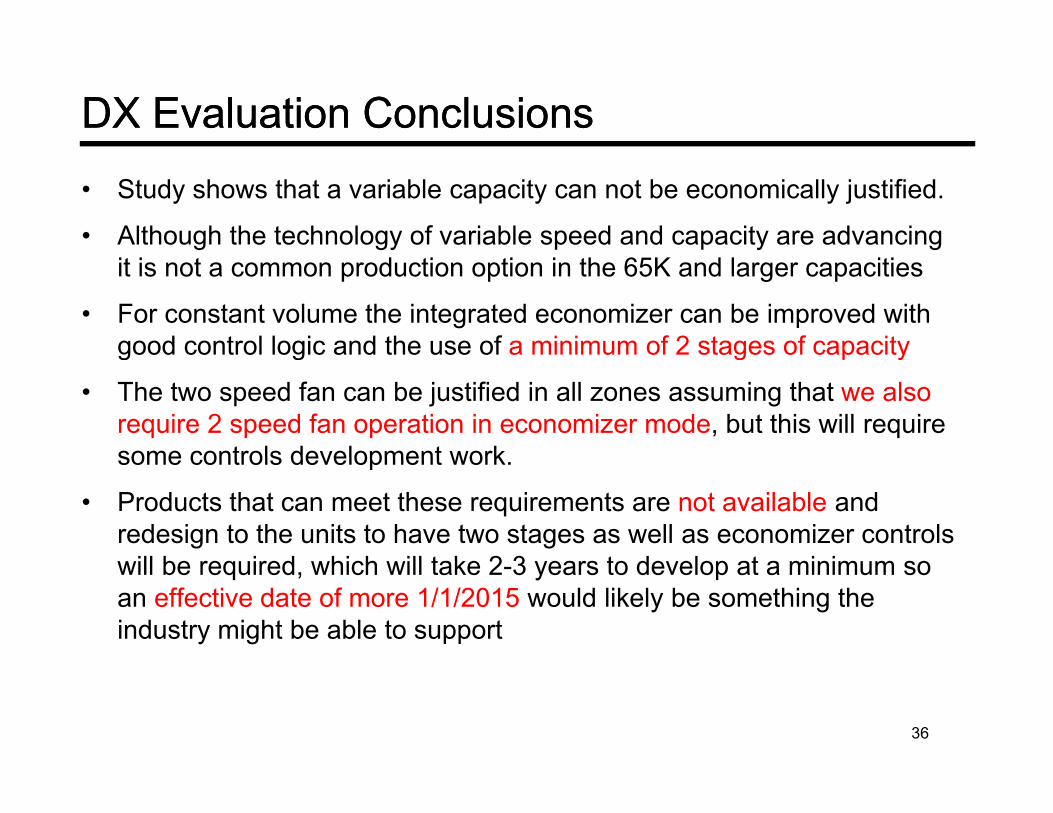
DX Evaluation ConclusionsDX Evaluation Conclusions• Study shows that a variable capacity can not be economically justified.
• Although the technology of variable speed and capacity are advancing it is not a common production option in the 65K and larger capacities
• For constant volume the integrated economizer can be improved with good control logic and the use of a minimum of 2 stages of capacityg g g p y
• The two speed fan can be justified in all zones assuming that we also require 2 speed fan operation in economizer mode, but this will require some controls development worksome controls development work.
• Products that can meet these requirements are not available and redesign to the units to have two stages as well as economizer controls
ill b i d hi h ill t k 2 3 t d l t i iwill be required, which will take 2-3 years to develop at a minimum so an effective date of more 1/1/2015 would likely be something the industry might be able to support
36

Chilled Water Coil ProposalChilled Water Coil Proposal• For the chilled water coils the CMP proposal is requiring 2 speed fans down to ¼ HP with
a lower speed of 50%• This will save energy and the first cost increase are not high assuming the units have gy g g
modulating chilled water coils• But the small fan coils, typically use 2 way on-off valves and only operation at 0 and
100% so they will not have to meet the proposed requirement as written.• If we elect to go forward with this then an additional requirement for a minimum of 2• If we elect to go forward with this then an additional requirement for a minimum of 2
stages of chilled water capacity control would be required• I have not looked into the availability of 2 stage water valves or the cost premium for
modulating, but I suspect the modulating will be very expensive relative to these small fan coil costscoil costs
• We also need to check with the manufacturers of these products and get their feedback on the options for at a minimum 2 stage water control valves.
• The economic analysis done for ASHRAE and Title 24 did include the cost of modulating valves and controls, but the estimate are somewhat optimistic.
• At the stated assumptions the payback period 7.3 to 7.8 years in high cooling zones and will be longer in cold zones.
• We have not yet tried to duplicate the savings but we would recommend for this round of• We have not yet tried to duplicate the savings, but we would recommend for this round of changes that we limit the change to 1 HP for Chilled Water Systems which will extend the 2 speed requirements from 5 HP to 1 HP. The ¼ savings look marginal at best..
37
Alternate Title 24 ProposalAlternate Title 24 Proposal
38
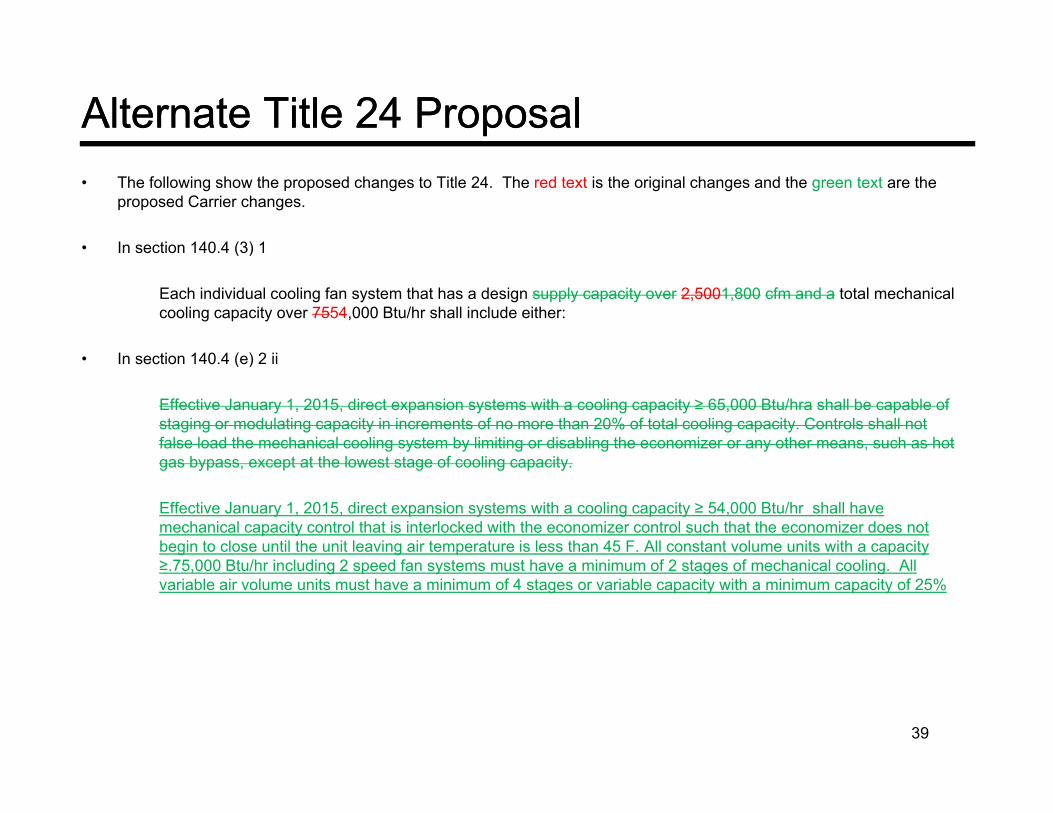
Alternate Title 24 ProposalAlternate Title 24 Proposal• The following show the proposed changes to Title 24. The red text is the original changes and the green text are the
proposed Carrier changes.
• In section 140.4 (3) 1In section 140.4 (3) 1
Each individual cooling fan system that has a design supply capacity over 2,5001,800 cfm and a total mechanical cooling capacity over 7554,000 Btu/hr shall include either:
I ti 140 4 ( ) 2 ii• In section 140.4 (e) 2 ii
Effective January 1, 2015, direct expansion systems with a cooling capacity ≥ 65,000 Btu/hra shall be capable of staging or modulating capacity in increments of no more than 20% of total cooling capacity. Controls shall not false load the mechanical cooling system by limiting or disabling the economizer or any other means, such as hot
b t t th l t t f li itgas bypass, except at the lowest stage of cooling capacity.
Effective January 1, 2015, direct expansion systems with a cooling capacity ≥ 54,000 Btu/hr shall have mechanical capacity control that is interlocked with the economizer control such that the economizer does not begin to close until the unit leaving air temperature is less than 45 F. All constant volume units with a capacity ≥ 75 000 Bt /h i l di 2 d f t t h i i f 2 t f h i l li All≥.75,000 Btu/hr including 2 speed fan systems must have a minimum of 2 stages of mechanical cooling. All variable air volume units must have a minimum of 4 stages or variable capacity with a minimum capacity of 25%
39

Alternate Title 24 ProposalAlternate Title 24 Proposal• In section 140.4 (e) 4
Air economizers and return air dampers on an individual cooling fan system that has a design supply capacity over 1,500 cfm and a total mechanical cooling capacity over 45,000 54,000 Btu/hr shall have the following over 1,500 cfm and a total mechanical cooling capacity over 45,000 54,000 Btu/hr shall have the following features:
• In section 140.4 (m)
• Current Proposal• Current ProposalFan Control. Each multiple zone system and single zone system listed in Table 140.4-D shall be designed to vary the airflow rate as a function of actual load. Single zone systems shall have controls and/or devices (such as two-speed or variable speed control) that will result in fan motor demand of no more than 50 percent of design wattage at 66 percent of design fan speed. Multiple zone systems shall include controls that limit the fan motor demand to no more than 30 percent of the total design wattage at 50 percent of design air volume when static pressure setno more than 30 percent of the total design wattage at 50 percent of design air volume when static pressure set point equals 1/3 of the total design static pressure.Variable air volume control for single zone systems. Effective January 1, 2012 all unitary air conditioning equipment and air-handling units with mechanical cooling capacity at ARI conditions greater than or equal to 110,000 Btu/hr that serve single zones shall be designed for variable supply air volume with their supply fans controlled by two-speed motors, variable speed drives, or equipment that has been demonstrated to the Executive Director to use no more energy. The supply fan controls shall modulate down to a minimum of 2/3 of the full fan speed or lower at low cooling demand.
•
40

Alternate Title 24 ProposalAlternate Title 24 Proposal• Alternate Proposal.
Each multiple zone system listed in table 140.4-D shall be designed to vary the airflow rate as a function of the load such that the fan motor demand is less than 20% at 50 percent of the design air volume when static pressure set point equals 1/3 of the total design static pressure. Variable air volume units shall have a minimum of 4 stages with a minimum stage of 25% or less.
For single zone systems with air-handling and fan-coil units with chilled-water cooling coils and supply fans with motors greater than or equal to 1 hp shall have their supply fans controlled by two-speed motors or variable-speed drives. At cooling demands less than or equal to 50% for proportionally controlled units and for 2 stage control units operating on the first stage, the supply fan controls shall be able to reduce the airflow to no greater than the larger of the following:
One half of the full fan speed, orThe volume of outdoor air required to meet the venti-lation requirements of Standard 62.1.
When operating at 50% airflow the fan motor demand shall be less than 25% of the full demand.All single zone air conditioning equipment and air handling units with direct expansion cooling and a cooling capacity atAll single zone air-conditioning equipment and air-handling units with direct expansion cooling and a cooling capacity at AHRI conditions greater than or equal to 75,000 Btu/h shall have their supply fans controlled by two-speed motors or variable-speed drives. Constant volume units at cooling demands less than or equal to 50% for proportionally controlled units and for 2 staged controlled units operating on first stage, the supply fan controls shall be able to reduce the airflow tono greater than the larger of the following:
Two-thirds of the full fan speed, orThe volume of outdoor air required to meet the venti-lation requirements of Standard 62.1.
When operating at 66% airflow the fan motor demand shall be less than 35% of the full demand.Both the chilled water and DX units shall also have a minimum of 2 stages of capacity and shall be capable of operating the economizer if required with 2 stage fan speed control with operation at low speed when the economizer capacity is lesseconomizer, if required, with 2 stage fan speed control with operation at low speed when the economizer capacity is less than 50%.
41

Alt t ASHRAE 90 1 P lAlt t ASHRAE 90 1 P lAlternate ASHRAE 90.1 ProposalAlternate ASHRAE 90.1 Proposal
42
Proposal ASHRAE 90.1 ChangesProposal ASHRAE 90.1 Changes
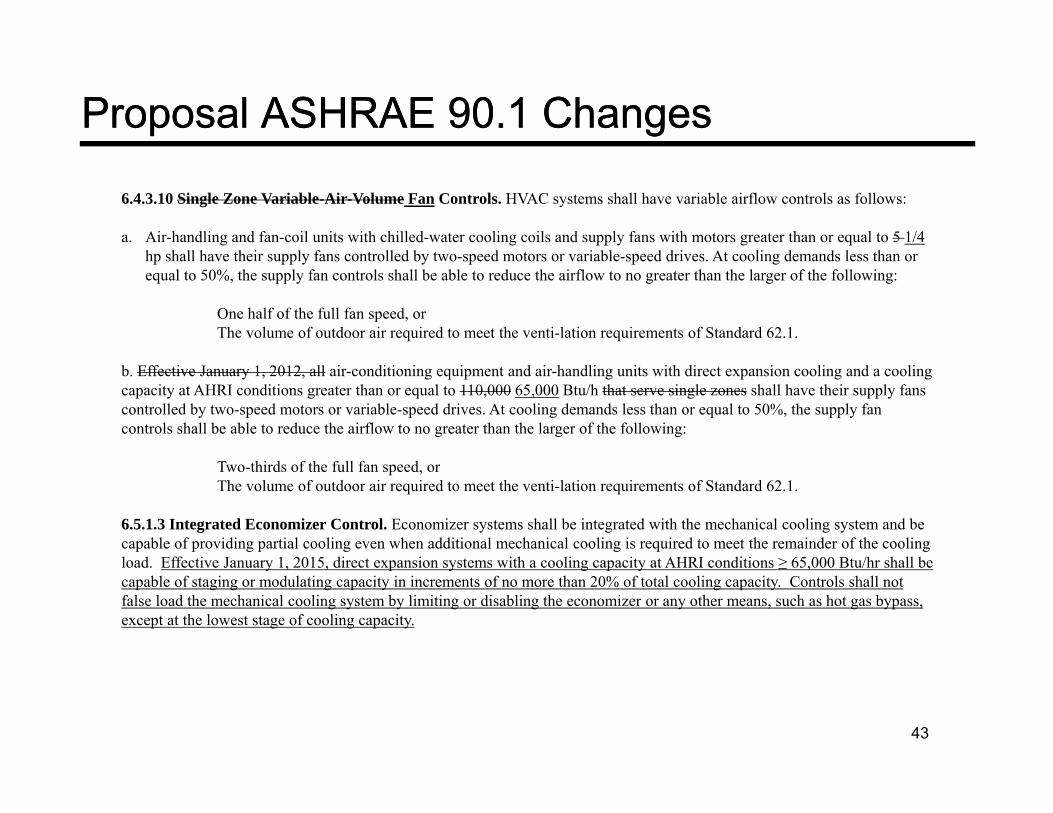
6.4.3.10 Single Zone Variable-Air-Volume Fan Controls. HVAC systems shall have variable airflow controls as follows:
a. Air-handling and fan-coil units with chilled-water cooling coils and supply fans with motors greater than or equal to 5 1/4 h h ll h th i l f t ll d b t d t i bl d d i At li d d l thhp shall have their supply fans controlled by two-speed motors or variable-speed drives. At cooling demands less than or equal to 50%, the supply fan controls shall be able to reduce the airflow to no greater than the larger of the following:
One half of the full fan speed, orThe volume of outdoor air required to meet the venti-lation requirements of Standard 62.1.
b. Effective January 1, 2012, all air-conditioning equipment and air-handling units with direct expansion cooling and a cooling capacity at AHRI conditions greater than or equal to 110,000 65,000 Btu/h that serve single zones shall have their supply fans controlled by two-speed motors or variable-speed drives. At cooling demands less than or equal to 50%, the supply fan controls shall be able to reduce the airflow to no greater than the larger of the following:
Two-thirds of the full fan speed, orThe volume of outdoor air required to meet the venti-lation requirements of Standard 62.1.
6.5.1.3 Integrated Economizer Control. Economizer systems shall be integrated with the mechanical cooling system and be capable of providing partial cooling even when additional mechanical cooling is required to meet the remainder of the coolingload Effective January 1 2015 direct expansion systems with a cooling capacity at AHRI conditions ≥ 65 000 Btu/hr shall beload. Effective January 1, 2015, direct expansion systems with a cooling capacity at AHRI conditions ≥ 65,000 Btu/hr shall be capable of staging or modulating capacity in increments of no more than 20% of total cooling capacity. Controls shall not false load the mechanical cooling system by limiting or disabling the economizer or any other means, such as hot gas bypass, except at the lowest stage of cooling capacity.
43
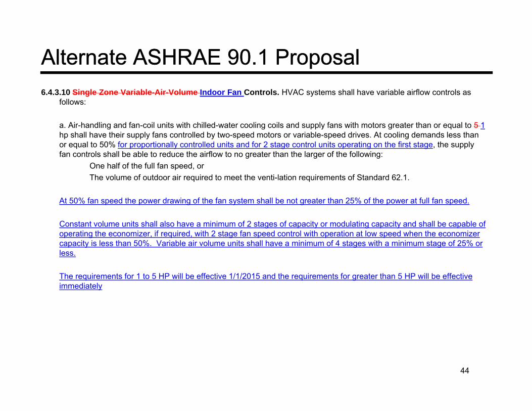
Alternate ASHRAE 90.1 ProposalAlternate ASHRAE 90.1 Proposal6.4.3.10 Single Zone Variable-Air-Volume Indoor Fan Controls. HVAC systems shall have variable airflow controls as
follows:
a. Air-handling and fan-coil units with chilled-water cooling coils and supply fans with motors greater than or equal to 5 1a. Air handling and fan coil units with chilled water cooling coils and supply fans with motors greater than or equal to 5 1hp shall have their supply fans controlled by two-speed motors or variable-speed drives. At cooling demands less than or equal to 50% for proportionally controlled units and for 2 stage control units operating on the first stage, the supply fan controls shall be able to reduce the airflow to no greater than the larger of the following:
One half of the full fan speed, orThe volume of outdoor air required to meet the venti-lation requirements of Standard 62.1.The volume of outdoor air required to meet the venti lation requirements of Standard 62.1.
At 50% fan speed the power drawing of the fan system shall be not greater than 25% of the power at full fan speed.
Constant volume units shall also have a minimum of 2 stages of capacity or modulating capacity and shall be capable of ti th i if i d ith 2 t f d t l ith ti t l d h th ioperating the economizer, if required, with 2 stage fan speed control with operation at low speed when the economizer
capacity is less than 50%. Variable air volume units shall have a minimum of 4 stages with a minimum stage of 25% or less.
The requirements for 1 to 5 HP will be effective 1/1/2015 and the requirements for greater than 5 HP will be effective i di t limmediately
44

Alternate ASHRAE 90.1 ProposalAlternate ASHRAE 90.1 Proposalb. Effective January 1, 2012, all air-conditioning equipment and air-handling units with direct expansion cooling and a cooling capacity at AHRI conditions greater than or equal to 110,000 75,000 Btu/h that serve single zones shall have their supply fans controlled by two-speed motors or variable-speed drives. At cooling demands less than or equal to 50% for proportionally controlled units and for 2 staged controlled units operating on first stage, the supply fan controls shall be able to reduce the airflow to no greater than the larger of the following:shall be able to reduce the airflow to no greater than the larger of the following:
Two-thirds of the full fan speed, orThe volume of outdoor air required to meet the venti-lation requirements of Standard 62.1.
When operating at 2/3 speed the fan motor system shall use no more than 35% of the power at full speed.
Constant Volume units shall also have a minimum of 2 stages of capacity and shall be capable of operating the economizer if required with 2 stage fan speed control with operation at low speed when the economizer capacity is less than 60%. Variable air volume units shall have a minimum of 4 stages of capacity with a minimum stage of 25% or less g p y gor variable capacity.
The requirements for 75,000 to 110,000 Btu/hr capacity are effective 1/1/2015 and greater than 110,000 Btu/hr are effective immediately
6.5.1.3 Integrated Economizer Control. Economizer systems shall be integrated with the mechanical cooling system and be capable of providing partial cooling even when additional mechanical cooling is required to meet the remainder of the cooling load. The mechanical capacity control shall be interlocked with the economizer control such that the economizer does not begin to close until the unit leaving air temperature is less than 45 F. All units with an economizer must have a minimum of 2 stages of mechanical cooling for constant volume units and minimum of 4 stages with a minimum of 25% g g gfor variable air volume effective 1/1/2015.
45