Embed Size (px)
Citation preview

Falling Head Test Versus ASTM Standard in Determining Infiltration of Porous
Asphalt
by
Fahad Shazad
B.Eng, N.E.D University of Engineering and Technology, Pakistan, 2011
A Project Report Submitted in Partial Fulfillment
of the Requirements for the Degree of
MASTER OF ENGINEERING
in the Department of Mechanical Engineering
© Fahad Shazad, 2017
University of Victoria
All rights reserved. This thesis may not be reproduced in whole or in part, by photocopy
or other means, without the permission of the author.

ii
Supervisory Committee
Falling Head Test Versus ASTM Standard in Determining Infiltration of Porous
Asphalt
by
Fahad Shazad
B.Eng, N.E.D University of Engineering and Technology, Pakistan, 2011
Supervisory Committee
Dr. Caterina Valeo (Department of Mechanical Engineering) Supervisor
Dr. Rishi Gupta (Department of Civil Engineering) Departmental Member

iii
Abstract
Supervisory Committee
Dr. Caterina Valeo (Department of Mechanical Engineering) Supervisor
Dr. Rishi Gupta (Department of Civil Engineering) Departmental Member
Porous asphalt has been increasingly used in increased urbanization areas due to its
positive environmental aspects. The porous asphalt is used to reduce the amount of runoff
from rain water and it also helps to improve the water quality near pavements. Porous
asphalt requires maintenance to preserve its effectiveness. A reliable testing method with
high repeatability and low error is required to determine the infiltration rate for the porous
asphalt. In this project two testing methods, Falling Head Infiltration Device (FHID) and
ASTM C1701 Constant Head Infiltration testing, are used to determine the infiltration rate
in three samples of porous asphalt of different porosity. For each testing method, a separate
device was used to find the method that provides high repeatability and accuracy. Results
showed that FHID has high repeatability compared to ASTM C1701 testing method.

iv
Table of Contents
Supervisory Committee ...................................................................................................... ii
Abstract .............................................................................................................................. iii
Table of Contents ............................................................................................................... iv
List of Tables ....................................................................................................................... v
List of Figures .................................................................................................................... vi
Acknowledgments ............................................................................................................ vii
Dedication ........................................................................................................................ viii
1. Introduction...................................................................................................................... 1
1.1 General Objective and Thesis Layout ........................................................................ 3
2. Literature Review ............................................................................................................ 5
2.2 Research Objective .................................................................................................. 11
2.3 Methodology to Achieve Research Objectives........................................................ 11
2.3.1 Infiltration Rates Testing Methods ................................................................... 11
2.3.2 ASTM C1701 - Standard Method for Infiltration Testing of In Place Pervious
Concrete ..................................................................................................................... 12
2.3.3 Falling Head Method ........................................................................................ 13
3. Experimental Setup ........................................................................................................ 15
3.1 Test Samples ............................................................................................................ 15
3.2 ASTM C1701 Testing Device ................................................................................. 16
3.3 Falling Head Infiltration Device .............................................................................. 17
4. Analysis and Results ...................................................................................................... 19
5. Conclusion and Recommendation ................................................................................. 24
6. References...................................................................................................................... 25
Appendix A - Test Results ................................................................................................. 27
Appendix B - Materials Used for Fabricating Testing Device .......................................... 29

v
List of Tables
Table 1 Testing schedule of porous asphalt samples......................................................... 19
Table 2 Infiltration test results of day 1 ............................................................................ 27
Table 3 Infiltration test results of day 2 ............................................................................ 27
Table 4 Infiltration test results of day 3 ............................................................................ 27
Table 5 Infiltration test results of day 4 ............................................................................ 28
Table 6 Infiltration test results of day 5 ............................................................................ 28
Table 7 Infiltration test results of day 6 ............................................................................ 28

vi
List of Figures
Figure 1 Conventional impervious pavement in comparison to permeable pavement ...... 2
Figure 2 NCAT field permeameter of four cylindrical tiers with different diameters ...... 10
Figure 3 Porous Asphalt sample A (middle) and sample B (left) sample C (right) .......... 15
Figure 4 Fibers used in asphalt samples ........................................................................... 15
Figure 5 Assembled ASTM C1701 testing setup ............................................................. 16
Figure 6 Gap of 0.5 inch between pavement and open end of the pipe ............................ 17
Figure 7 Two components of FHID .................................................................................. 17
Figure 8 Inside of assembled FHID .................................................................................. 18
Figure 9 Assembled FHID ................................................................................................ 18
Figure 10 ASTM C1701 Infiltration rate for porous asphalt............................................. 20
Figure 11 FHID Infiltration rate for porous asphalt.......................................................... 21
Figure 12 Sample-A Infiltration rate with ASTM C1701 and FHID................................ 22
Figure 13 Sample-B Infiltration rate with ASTM C1701 and FHID................................ 22
Figure 14 Sample-C Infiltration rate with ASTM C1701 and FHID................................ 23
Figure 15 RedGard membrane........................................................................................... 29
Figure 16 2'' diameter PVC pipe........................................................................................ 29
Figure 17 Paint brush ....................................................................................................... 29
Figure 18 Flexible coupling ............................................................................................. 29
Figure 19 Gorilla tape ...................................................................................................... 30
Figure 20 Plasticine modelling clay ................................................................................. 30
Figure 21 5 gallon water bottle ........................................................................................ 30
Figure 22 2'' dia PVC valve ............................................................................................. 30
Figure 23 Concrete forming tube ..................................................................................... 31
Figure 24 Hack saw ......................................................................................................... 31
Figure 25 Measuring tape ................................................................................................ 31
Figure 26 3/4'' plywood .................................................................................................... 31
Figure 27 Fold knife ......................................................................................................... 31
Figure 28 Silicone ............................................................................................................ 31
Figure 29 Teflon tape ....................................................................................................... 32

vii
Acknowledgments
I would like to acknowledge the immense support and guidance provided by my supervisor,
Dr. Caterina Valeo for completing the project. I am thankful to my managers Mr. Jason
Smith and Mr. Richie Windolf for their assistance and support. Special thanks to my work
colleague Mr. Tom Dawson, Mr. Randy Ware and Mr. Nick Mankwald for their ideas that
helped me in making a reliable testing device.
Finally, I am grateful to Dr. Rishi Gupta and Dr. Phalguni Mukhopadhyaya for serving as
committee member and examination chair respectively.

viii
Dedication
TO MY PARENTS AND SIBLINGS

1. Introduction
In the developed world, most cities are dependent on piping network for storm water
drainage. Most of these systems were built in 19th century. The traditional system
distributes storm runoff water to sewer systems. These piping system are expensive to
develop and maintain. Furthermore, over a long period of time these systems become
inefficient and ineffective [1]. Development of permeable pavement system (PPS) has
challenged the traditional systems. Permeable pavement principle is to collect, treat and
infiltrate the surface runoff to recharge ground water. PPS reduce the dependence and load
on traditional piping systems. Permeable pavement allows storm water runoff to infiltrate
through the voids in the surface into underlying reservoir [2]. Porous asphalt usually
contains 15% air voids and is an environment friendly paving material. In regions of high
level of precipitation, permeable pavement is highly effective. The voids in the permeable
pavement reduce water runoff which increases the riding safety and quality. Porous asphalt
increases the visibility by reducing the reflected light from road surface and decreases
hydroplaning. Porous asphalt is mostly deployed in areas which are considered low traffic
zone such as parking lots, driveways and sidewalks [3].
The open pores permeable asphalt enables high infiltration rates for water. Slowly the pores
of permeable asphalt start to clog with debris and dirt which reduces the effectiveness and
permeability. Eventually the pores become completely clogged which changes the
permeable pavement to an impervious pavement. To maintain the functionality of PPS,
they must be maintained properly. A broom or a leaf blower can be used for clearing surface

2
debris but a rigorous maintenance method like vacuum sweeping or power washing is
required to clear deeper pores [4].
Determining the infiltration rates of PPS on a virgin sample are important to properly
maintain and ensure long lifespan of permeable pavement system. The infiltration rate in
this project is calculated through two different methods. First method is the ASTM C1701-
Standard Method for Infiltration Testing of In Place Pervious Concrete [14]. For second
method, a falling head infiltration device (FHID) is built in the lab and used for finding the
infiltration rate. The devices were tested on three samples of different permeability
containing fibers. The performance parameters such as strength, durability, noise level,
lifespan, rutting resistance and the water sensitivity of asphalt are greatly influenced by the
fibers [5]. The basic difference between conventional pavement and impervious pavement
is shown in figure 1. Unlike conventional pavement, impervious pavement allows
infiltration, evaporation and reduces the quantity of runoff pollutants.
Figure 1 Conventional impervious pavement in comparison to permeable pavement [6]

3
One of the most common problems of porous asphalt is binder loss by drainage due to
reduction in aggregates content. In the first generation of porous pavement high binder
percentages were used to maintain better connection among the aggregates, however this
lead to hardening issues. Due to environmental concerns, the researchers are looking into
different eco-friendly fibers. In porous pavements today a variety of fiber types are used
which include cellulose, polymer, mineral, glass fiber, recycled fibers from old tires and
carpet fibers [7].
1.1 General Objective and Thesis Layout
The project work has one objective and that is to find a reliable testing method for finding
infiltration rate on pervious pavement (asphalt). Previous testing conducted by the students
at the University of Victoria showed that the infiltration testing results did not have high
repeatability when using ASTM C1701 method. The two main reasons were lack of good
sealant between testing ring and pavement and the lack of a good testing device for properly
maintaining a constant head. In this project, three different asphalt samples are used for
testing. The samples are coarse compared to the traditional asphalt and contain fibers which
is a mix of aramid, kevlar and polyolefin. One set of testing is done using the ASTM C1701
standard with the newly designed experimental setup to achieve better repeatability.
Second set of testing is done using Falling Head Infiltration Device (FHID) which was
fabricated by a student however the device is rebuilt using new techniques that reduced the
water leakage to minimal.
Chapter 2 of the report includes literature review of several research papers. The topic of
the research and the methodology used for achieving the test results are summarized in this
chapter.

4
Chapter 3 consists of the designing and fabrication of testing device and experimental setup.
Chapter 4 provides details of the experiments conducted for finding the infiltration rates,
results and analysis.
Chapter 5 concludes the findings of the infiltration testing with the two methods and
recommendation for future work.

5
2. Literature Review
Kuldip Kumar, Joseph Kozak, Lakhwinder Hundal, Albert Cox, Heng Zhang and Thomas
Granato reported the measured in-situ infiltration performance of permeable pavers,
permeable concrete and permeable asphalt over a four year period since construction of a
parking lot. The infiltration rates were measured by using ASTM C1701 method. The
decline in infiltration rates after one year of use was marginal however between two to four
years, the infiltration rates declined significantly due to clogging of pores either by shear
driving and degrading of permeable surfaces or dry deposition of particles. The permeable
asphalt section had an area of 1311m2 with 38 parking slots. All slots in the permeable
asphalt were always full throughout the working days during the year. During winter, snow
from the parking lot was removed and de-icing salt which contained a mixture of chloride
salts of sodium, calcium and magnesium was used as in a normal parking lot. The porous
asphalt section consisted of open-graded asphalt of 10 cm layer over an open graded fill
base 30 cm deep consisting of CA-7 aggregate above native soil. LINQ 180 EX separation
geotextile separated aggregate base from subgrade native soil. Spray water followed by
sweeping was used for asphalt maintenance twice annually. The overall infiltration
performance depends on the permeability of the surface. During first year the average
infiltration rate for porous asphalt was 31.1 mm/s. The infiltration rate declined during next
three year and was 30.6 mm/s, 24.4 mm/s and 9.1 mm/s. The results showed that only
marginal declines in infiltration rates was noted after one year of usage after which the
decline accelerated. In the fourth year, the infiltration rate for porous asphalt had declined
as much as 70% in parking slots. At the end of four year study the physical condition of
permeable asphalt had declined but the infiltration rate was still approximately 380 times
6
higher than most rainstorm events impacting the study area and no runoff flow was
observed at the parking lot [8].
Bin Yu, Liya Jiao, Fujian Ni and Jun Yang launched a five year tracking programme to
collect performance data of porous asphalt section paved in Yan-Tong highway in Jiangsu
Province of China. The results from the field performance of the test section were used for
validating and improving porous asphalt design. The investigation covers permeability,
roughness, rutting and skid resistance on truck lane, passing lane and passenger vehicle
lane. The highway has three lanes per direction with a speed limit of 120km/h. The 17km
porous asphalt section lies in heavy traffic corridor which opened for traffic in November
2005. The meteorological data from January 2006 to July 2009 shows the temperature
exceed 30º C in summers. The annual precipitation ranges between 990-1060 mm with 120
rainy days per year. The porous asphalt section had limestone aggregate in the middle and
bottom layers and basalt aggregate in the surface layer. The permeability of porous asphalt
section was investigated on the truck and passenger vehicle lane. The Subgrade and
Pavement Testing Method for Highway Engineering (JTJ059-95) (Research Institute of
Highway Ministry of Communication, 1995) was followed for testing. The tests were
replicated at each spot for three times to assure reliability. The amount of water (ml)
penetrated into the porous asphalt within 15 sec were reported for the results. At the end of
five year investigation the permeability of passenger vehicle lane was in better condition
with efficiency of 600-1000ml/15s whereas the permeability of truck lane was less than
600ml/15sec. The permeability of the porous asphalt increased initially then decreased with
peak values occurring between 15 and 18 months after construction. The results of field
investigation showed that the permeability and noise reduction merits associated with the
porous asphalt reduced substantially with time [9].

7
Ian Anderson, Mark Suozzo and Mandar M. Dewoolkar evaluated hydraulic parameters
and long term infiltration monitoring and cleaning operations of pervious concrete with
3/8’’ aggregate. The study compared methods to determine infiltration rate in the field to
the laboratory measurement of hydraulic conductivity. The objective of the investigation
was to determine relation among single ring, double ring and falling head infiltration rate
in the field and compare the field methods to hydraulic conductivity measurement in the
laboratory. Two facilities were monitored for changes in infiltration rate over time in
Vermont, USA. The facilities have 6’’ layer of porous concrete with 34’’ gravel sub-base.
The infiltration rates with single and double ring infiltrometer were determined in
accordance with ASTM C1701. A ring of 12’’ diameter was used for single ring method;
however, for double ring infiltrometer a second ring of 24’’ was placed around the 12’’
inner ring. The falling head infiltrometer device had a 2’x2’x3/4’’ base with a circular hole
attached to a 4’’ internal diameter stand pipe and the infiltration rate was calculated by
measuring the time taken for the top level to drop from 15’’ to 3’’ above porous asphalt.
A linear correlation of 1.0 : 1.8 : 1.5 : 9.0 was found among hydraulic conductivity, single
ring, double ring and falling head infiltrometer testing. The effectiveness of various
cleaning methods was also evaluated. Cleaning methods effectiveness for average
restoration rates was 10% for hand vacuuming, 21% for street sweeping, 30% for vacuum
truck cleaning, 85% for pressure washing and 100% for combined pressure washing and
cleaning. The falling head method used higher head value compared to ASTM method
which increased the amount of lateral flow resulting in inflated infiltration rates. The
difference in geometry resulted in different infiltration values. The 4’’ diameter of falling
head infiltrometer is smaller than the 12’’ diameter of single ring infiltrometer; as a result
the ratio of perimeter to area is higher for falling head compared to single ring infiltrometer.

8
It was observed that the lateral flow is influenced by the ratio of perimeter to area, thus the
falling head infiltrometer had higher infiltration value. The correlation between single ring
and falling head method was consistent over a wide range of infiltration values which
suggests that the falling head can be used to predict infiltration values obtained from the
ASTM C1701 single ring method [10].
Márcia Lopes Afonso, Marisa Dinis-Almedia and Cristina Sena Fael investigated the
performance of porous asphalt mixture with cellulosic fiber additive. The investigators
used a double porous layer to improve runoff and reduce clogging problems. Two mixtures
with and without cellulosic fibers were produced containing fine and coarse aggregates.
Four different mixtures were produced (1.Porous asphalt without fibers, with fine
aggregate 2.Porous asphalt without fibers, with coarse aggregate 3.Porous asphalt with
fibers, with fine aggregate 4.Porous asphalt with fibers, with coarse aggregate) and they
were evaluated for the performance under stiffness, permeability, water sensitivity and
deformation testing. Test results suggested that the porous asphalt with fine aggregate is
more likely to have water presence than mixture with coarse aggregate since coarse
aggregate have more air voids [7].
Robert A. Brown and Michael Borst conducted a research project to measure the water
balance for quantifying the evaporation from a lined permeable pavement section. The
pervious concrete (PC), porous asphalt (PA) and permeable interlocking concrete pavers
(PICP) were used in the investigation. All infiltrating water was captured by an
impermeable liner installed in four 11.6 m by 4.74 m sections 0.4 m below the surface. The
area ratio between impervious areas to permeable pavement was 0.66:1. The water level
for 24 months was measured in the collection tanks. The researchers concluded that the
evaporation increased during the warmer months and the average cumulative evaporation

9
was about 5.2% of the total rainfall for permeable pavement. Cumulative evaporation from
pervious concrete, permeable interlocking concrete and porous asphalt was ranging from
6.5–7.6%, 3.9–5.8%, and 2.4–5.6% of the cumulative rainfall, respectively. The difference
in evaporation between PICP and PA was not significant whereas porous concrete has the
largest cumulative evaporation [11].
Hui Lin, Masoud Kayhanian and John T. Harvey compared permeability measurement of
permeable pavements using ASTM C1701 and National Center for Asphalt Technology
(NCAT) permeameter methods. The study was conducted to compare the results obtained
from field testing on a variety of permeable pavements. Six different permeable pavement
surfaces types included pervious concrete, porous asphalt and permeable interlocking
concrete pavers. Silicone gel was used as sealing material for testing. Through the
comparison it was found that both methods (NCAT and ASTM) are effective in measuring
the permeability of all pavement types. The permeability measured through ASTM C1701
method was 50-90% (75% on average) lower than those measured with NCAT. The
reliability and accuracy of the measured permeability is dependent on the permeameter
cylinder diameter, use of larger diameter produced less variation in results. The NCAT
method uses falling head principle. The NCAT method was never published; however it is
widely used in assessments of pervious asphalt and thin layers of open graded asphalt. The
testing procedure requires filling water in the cylinder in tier 4 or in tiers 3, 2 or 1 and
measure the time required to drop the height of each of the permeameter tiers. The testing
device is shown in figure 2. The coefficient of permeability also known as saturated
hydraulic conductivity, Ks can be calculated by using equation 1 [12].
............. Equation 1

10
Where;
Ks= saturated hydraulic conductivity, cm/s
a = inside cross-sectional area of inlet standpipe, cm2
l = thickness of the permeable porous asphalt or pervious concrete pavement, cm
A = cross-sectional area of tested pavement, cm2
t = average elapsed time of water flow between timing marks (t1-t2), s
h1= hydraulic head on pavement at time t1, cm
h2 = hydraulic head on specimen at time t2, cm
Figure 2 NCAT field permeameter of four cylindrical tiers with different diameters

11
2.2 Research Objective
The objective of the research is to make a reliable testing method that could be used on
different porous pavement to determine the infiltration rate. The porous pavements become
clogged with dirt and debris overtime and hence require maintenance. A reliable infiltration
test would help to build a maintenance schedule.
2.3 Methodology to Achieve Research Objectives
Infiltration rates of permeable pavement are high when they are first installed. The
infiltration test procedure used in the past has been inconsistent and the variation in results
is very large. Most test procedures are based on using single or double ring infiltrometer
test. Ring infiltrometer was originally designed to determine the hydraulic conductivity in
soils. For high hydraulic conductivity single ring infiltrometer are commonly used. A
falling head or constant head method can be used for pavement with high infiltration rate.
2.3.1 Infiltration Rates Testing Methods
Most standards for testing the infiltration rate are based on ASTM D3385 [13] which were
primarily developed for testing on soil. Since soil has much lower infiltration rate compared
to permeable pavement therefore ASTM D3385 cannot be used on highly pervious
pavement. There is currently no standard to test infiltration rate on permeable pavement
however ASTM C1701 and ASTM C1781 have been developed for infiltration testing on
porous concrete and porous interlocking concrete pavers, respectively. These standards are
very similar except for the fact that ASTM C1781 specifies where to place the ring on the
interlocking pavers.

12
2.3.2 ASTM C1701 - Standard Method for Infiltration Testing of In Place Pervious
Concrete
The ASTM C1701 standard is a constant head method that requires a ring of 12’’ diameter
to be adhered to the pavement surface, pouring a known mass of water onto the pavement,
maintain a constant head between 0.4 – 0.6 inch and recording the time taken for water to
disappear from top of the surface. The testing method requires a user to pre-wet the surface
using 8 lb. of water. If the time taken for water during pre-wetting is less than 30 sec, use
40 lb. of water for infiltration testing. During pre-wetting, if the time taken for water to
infiltrate completely into the pavement is greater than 30 sec, use 8 lbs of water. The
infiltration rate is calculated using equation 2.
………………. Equation 2
Where;
I = Infiltration rate (in/h)
M = Mass of infiltrated water (lbs.)
K = 126870 [(in3.s)/(lb.h)] (needed to convert recorded data to the infiltration rate)
t = Time required for measured amount of water to infiltrate (sec)
D = Inside diameter of infiltration ring (in)
The limitation to this standard is that the next test cannot be performed before 24 hours
have elapsed since the last precipitation or last test. However, if two tests are conducted
on same day at the same location the infiltration rate can be calculated as the average of
the two tests.

13
The ASTM testing method is highly user dependent as maintaining the constant head
between such a small ranges (0.4 - 0.6 inch) is very challenging. Achieving a high
repeatability with low error in ASTM C1701 testing is difficult.
2.3.3 Falling Head Method
The FHID method was also used to determine the infiltration rate on same samples. With
FHID, same quantity of water is used and the testing ring size is also 12’’ as used for ASTM
C1701 testing. However, with falling head infiltration test all the water is dumped onto the
permeable pavement at once instead of maintaining constant head above the surface. This
method leads to a lower time taken by water to disappear which translates to high
infiltration rates. A 12’’ concrete forming tube was used to make falling head infiltration
device. The device consists of two sections. One section fits within the 12’’ section and sits
on top of the bottom surface of outside section. The surface where the two section meet is
made out of plastic sheets and rubber. The plastic sheets and rubber are bonded together
using caulking glue. The plastic sheet and rubber had three holes cut of identical size and
pattern. When the top section is rotated the holes align and close, allowing the water to be
filled in the inner section. After filling water, the inner section could be rotated either
clockwise or anti-clockwise to release water for infiltration testing. The inside and outside
of the forming tube was covered with water proofing and crack prevention membrane to
prevent the forming tube from becoming wet and soggy.
The ASTM C1701 standard doesn’t specify the falling head for water onto the pavement.
The actual total falling head with FHID was 11 inches. A soft modeling material plasticine
was used as sealing material. The use of plasticine provided excellent sealing between the
pavement and the testing ring. Plasticine is easy to form into a role which was placed
around the outside of testing ring and gently compressed to make a seal. It is very easy to

14
remove plasticine from porous pavement. Using plasticine amount of water leaking in
lateral direction was negligible (few drops of leakage only). The testing method with FHID
is similar to ASTM which requires a user to pre-wet the surface using 8lb of water. Unlike
ASTM standard where water used for infiltration testing is 40lb if the pre-wetting time is
greater than 30 seconds, the FHID method doesn’t require 40lb of water even if the pre-
wet timing is less than 30 seconds. With 40lb of water the initial head is very high which
forces the water to flow underneath the sealant and the water comes out of the pavement
on the other side of the testing ring. FHID requires entire quantity of water to be dumped
onto the porous pavement at once. The difference in filtration rates between 8lb to 40lb of
water is upto 8 times which is unrealistic for same sample. Therefore the time taken for
pre-wet during FHID is not much of importance except for the fact that pre-wetting brings
different samples of the pavements to same initial testing conditions.

15
3. Experimental Setup
3.1 Test Samples
Infiltration tests were performed on three asphalt samples (A, B and C) which were received
from a local paving company located in Vancouver Island.
Figure 3 Porous Asphalt sample A (middle) and sample B (left) sample C (right)
Each test sample was approximately 3 feet by 1.5 feet in size. On each sample only one
location could be selected for testing. The relatively flat surface for 12inch diameter test
ring was found to be right in the middle of the sample hence this location was selected for
testing. Each sample had a different porosity and contained fibers as binders.
Figure 4 Fibers used in asphalt samples

16
3.2 ASTM C1701 Testing Device
The equipment used for ASTM C1701 testing are a 12’’ diameter and 9’’ high fiber
reinforced plastic (FRP) ring, wooden stand, 5 gallon water bottle, 2’’ diameter pipe, PVC
valve, flexible coupling and a gorilla tape. Building the testing setup starts with placing the
FRP ring onto the porous pavement. After placing the ring on the sample the ring was
adhered to the pavement using plasticine. The wooden stand is placed on top of the
pavement to support a 5 gallon water bottle. After placing the bottle upside down on top of
the stand the piping is connected to the valve on the bottle.
Figure 5 Assembled ASTM C1701 testing setup
The length of piping is selected carefully such that when the experimental setup is
assembled on the field, the gap between the pipe and the asphalt is approximately 0.5’’.This
can easily be done by field measuring the distance between the valve and asphalt to
calculate the required length of pipe. The pipe was field cut using hacksaw.

17
Figure 6 Gap of 0.5 inch between pavement and open end of the pipe
This gap of 0.5 inches is maintained strategically since with the above setup when the valve
is full opened the device will maintain the level automatically between 0.4 to 0.6’’.
3.3 Falling Head Infiltration Device
Two 12 inch diameter sections made of concrete foaming tube were built for the falling
head infiltration device. The sections were made such that one section could fit inside the
other section. The other equipment used for FHID includes a wooden stand, 5 gallon water
bottle, 2 inch dia pipe, PVC valve, reducer and gorilla tape.
Figure 7 Two components of FHID

18
The component on the right in above figure sits on top of the porous asphalt whereas the
component on the left fits inside the component that adheres to asphalt. The contact area
between the outer ring and asphalt is sealed by using plasticine.
Figure 8 Inside of assembled FHID
After assembling the FHID, the inside component is rotated to close the window. This
allows the water to stay in the inner section until the test starts. The concrete foaming tube
was coated with water proofing membrane which made it reusable.
Figure 9 Assembled FHID

19
4. Analysis and Results
The testing on each sample could only be performed 6 days due to time constraints.
Alternate day were selected for one method of testing for each sample as shown in the table
1.
Table 1 Testing schedule of porous asphalt samples
For ASTM C1701 as well as falling head testing pre-wetting with 8lb of water was
performed before the test stage. The test results over a period of 6 days are shown in the
table 2 to 7 in the appendix A.
The tests results shown in the tables (2-7) of appendix A are for the testing conducted on
three samples (A, B, C) over a period of 6 days. The rest period between the tests is 24
hours approximately. Figure 10 shows the infiltration rate using ASTM C1701 on each
sample over 6 days period.

20
Figure 10 ASTM C1701 Infiltration rate for porous asphalt
The result shows that the infiltration rates for sample A and C were high on first day of
testing but it stabilized during the next two testing. The infiltration rates of sample B which
started on 2 day can be seen to have less variation. The reason for such a behavior of the
asphalt could be that on day 1, the samples not only let the water infiltrate through the pores
but the voids and open spaces inside the sample hold some of the water and the fiber binders
also absorbed negligible quantity of water. Since fibers are in very small quantity therefore
it can be estimated that the amount of water the sample holded is significant. In case of
sample B the infiltration rate remain very stable, this is because the sample B is tested for
FHID on day 1 hence the sample is already wet from previous day of testing. Therefore,
the infiltration rate has good repeatability for sample B. The variability in results is likely
due to the height of the pipe which is ideally set at 0.5 in but in the field testing this height
varied slightly during each test which resulted in variable head of water.

21
While ASTM C1701 testing was conducted on one set of sample the other set of samples
were tested with falling head method. The results of FHID on three samples over a period
of 6 days are shown in figure 11.
Figure 11 FHID Infiltration rate for porous asphalt
The testing with FHID showed very promising results with good repeatability. The tests on
day 2 onwards showed very similar result. There was some difference noticed in sample B
values which showed a high infiltration rate on day 1 compared to later tests. Again this is
because when the sample B was first tested the asphalt was dry and holded some of the
infiltrated water in the voids and holes which affected the test and resulted in higher
infiltration rate on day 1.If the infiltration rates from figure 10 and 11 are compared it can
be seen that the infiltration rates with FHID method were found to be much higher when
compared to ASTM C1701 standard. However the high infiltration rates with FHID are not
a major concern as the consistency and repeatability in values over time for same location
is more important.

22
The ASTM C1701 standard for is basically derived from ASTM D3385 [12]. The ASTM
D3385 is designed for the determination of infiltration rate of soil. Soil has strong capillary
action; the pre-wetting in ASTM C1701 is incorporated to adjust for capillary action in
concrete. Collected data for pervious asphalt was analyzed to see if pre-wetting in needed
in asphalt samples at all.
Figure 12 Sample-A Infiltration rate with ASTM C1701 and FHID
Figure 13 Sample-B Infiltration rate with ASTM C1701 and FHID

23
Figure 14 Sample-C Infiltration rate with ASTM C1701 and FHID
The capillary action is not as significant in porous asphalt as it is in soil. However test
results suggest that pre-wet helps bring the asphalt to same initial testing conditions. The
infiltration test performed after the pre-wet produced very similar result but the pre-wet
time varied mostly, especially on first day of testing. Therefore when determining
infiltration rates through ASTM C1701, it is recommended to perform pre-wetting before
performing the infiltration testing. When using FHID on sample B the difference in results
between pre-wetting and infiltration testing was not significant even on the first day of
testing. Therefore with FHID it is totally up to the user to either choose pre-wetting or not
as it doesn’t affect the results by a great deal.

24
5. Conclusion and Recommendation
The test results showed that the falling head device produced more consistent results
compared to the test conducted using ASTM C1701. The use of plasticine as sealant had
a huge impact on the accuracy and repeatability of results. The plumber’s putty which is
suggested in ASTM standard and used by several investigators does not provide sufficient
sealing. The result showed that falling head method is simple and easy to use for
determining infiltration rate. Among the three samples, Sample C was found to have the
highest infiltration rate followed by sample B and sample A. Pre-wetting of the sample is
suggested when ASTM C1701 method is used, the results with FHID were highly
consistent so pre-wetting is not required. Since the test samples were not in situ, the results
may vary when the same sample is in situ. Since the samples are placed on wooden pallets
few inches off the ground there is relatively lower resistance to flow of water. The FRP
ring used for conducting the ASTM C1701 tests was very stable and thus the sealant could
be compressed much harder to the ring to achieve good seal. The components of FHID
were made from concrete forming tube with water proofing membrane which helped the
device retain its shape. If water proofing membrane is not used, it is recommended to use
FRP or poly vinyl carbonate or steel for making the components of FHID.
25
6. References
[1] Miklas Scholz, Piotr Grabowiecki, “Review of permeable pavement systems”,
Institute for Infrastructure and Environment, School of Engineering and Electronics,
The University of Edinburgh, Scotland, UK, 2006
[2] Permeable Pavement, Version 1.8, March 1, 2011 (Available online:
http://vwrrc.vt.edu/swc/NonPBMPSpecsMarch11/VASWMBMPSpec7PERMEAB
LEPA VEMENT.html)
[3] Cesare Sangiorgi, Shahin Eskandarsefat , Piergiorgio Tataranni, Andrea Simone,
Valeri Vignali, Claudio Lantieri, Giulio Dondi, “A complete laboratory assessment
of crumb rubber porous asphalt”, D pt. of Civil, Chemical, Environmental and
Materials Engineering, University of Bologna, V.le Risorgimento 2, 40136 Bologna,
Italy, 2016
[4] R.J. Winston, W.F. Hunt, A. Al-Rubaei, G. Blecken, M. Viklander, “Maintenance
measures for preservation and recovery of permeable pavement surface infiltration
rate. The effects of street sweeping, vacuum cleaning, high pressure washing, and
milling” Journal of Environmental Management”, vol. 169, pp. 132-144, 2016
[5] Yanping Sheng, Haibin Li, Ping Guo, Guijuan Zhao, Huaxin Chen and Rui Xiong,
“Effect of Fibers on Mixture Design of Stone Matrix Asphalt”, School of Materials
Science and Engineering, Chang’an University, Xi’an 710064, China, 2017
[6] J. Sansalone , X. Kuang and V. Ranieri, “Permeable Pavement as a Hydraulic and
Filtration Interface for Urban Drainage”, Journal of Irrigation and Drainage
Engineering, Vol. 134, No. 5, October 1, 2008
[7] Márcia Lopes Afonso, Marisa Dinis-Almeida , Cristina Sena Fael, “Study of the
porous asphalt performance with cellulosic fibres”, Centre of Materials and Building
Technologies, University of Beira Interior, 6200-358 Covilhã, Portugal, 2016
[8] Kuldip Kumar, Joseph Kozak, Lakhwinder Hundal, Albert Cox, Heng Zhang,
Thomas Granato, “In-situ infiltration performance of different permeable pavements
in an employee used parking lot - A four-year study”, Monitoring and Research
Department, Metropolitan Water Reclamation District of Greater Chicago, 6001
West Pershing Road, Cicero, IL, USA, 2015

26
[9] Bin Yu, Liya Jiao, Fuji n Ni & Jun Yang, “Long-term field performance of porous
asphalt pavement in China”, School of Transportation, Southeast University,
Sipailou #2, Nanjing 210096, People’s Republic of China, 2014
[10] Ian A. Anderson, Mark Suozzo and Mandar M. Dewoolkar, “Laboratory and Field
Evaluations of Pervious Concrete”, University of Vermont Transportation Research
Center, TRC Report 13-007, October 2013
[11] Robert A. Brown and Michael Borst, “Quantifying evaporation in a permeable
pavement system”, U.S. Environmental Protection Agency, 2890 Woodbridge Ave.,
MS104, Edison, USA, 2015
[12] Hui Li, Masoud Kayhanian, John T. Harvey, " Comparative field permeability
measurement of permeable pavements using ASTM C1701 and NCAT permeameter
methods", Department of Civil and Environmental Engineering, University of
California, Davis, CA, USA, 2013
[13] ASTM, “ASTM D3385 - Standard Test Method for Infiltration Rate of Soils in Field
Using Double-Ring Infiltrometer”, ASTM International, West Conshohocken, PA,
2009
[14] ASTM, “ASTM C1701 – Standard Test Method for Infiltration Rate of In Place
Pervious Concrete”, ASTM International, West Conshohocken, PA, 2009
[15] Google image search, www.google.com/

27
Appendix A - Test Results
Table 2 Infiltration test results of day 1
Table 3 Infiltration test results of day 2
Table 4 Infiltration test results of day 3
Table 5 Infiltration test results of day 4
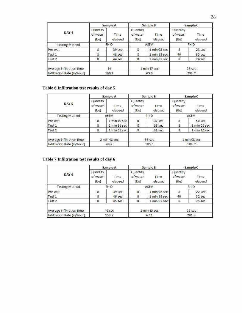
28
Table 6 Infiltration test results of day 5
Table 7 Infiltration test results of day 6

29
Appendix B - Materials Used for Fabricating Testing Device
Figure 15 RedGard membrane [15]
Figure 16 2'' diameter PVC pipe [15]
Figure 17 Paint brush [15]
Figure 18 Flexible coupling [15]

30
Figure 19 Gorilla tape [15]
Figure 20 Plasticine modelling clay [15]
Figure 21 5 gallon water bottle [15]
Figure 22 2'' dia PVC valve [15]

31
Figure 23 Concrete forming tube [15]
Figure 24 Hack saw [15]
Figure 25 Measuring tape [15]
Figure 26 3/4'' plywood [15]
Figure 27 Fold knife [15]
Figure 28 Silicone [15]

32
Figure 29 Teflon tape [15]


![PERFORMANCE TESTING OF A · 2018-03-09 · [5] ASTM D3977-97 (2013), Standard Test Methods for Determining Sediment Concentration in Water Samples. [6] ASTM D422-63, Standard Test](https://img.pdfslide.us/doc/110x75/5e8e7597d9069715ad27d296/performance-testing-of-a-2018-03-09-5-astm-d3977-97-2013-standard-test-methods.jpg)