Embed Size (px)
Citation preview

DISCLAIMER: This document was developed as part of the requirements of an electrical and
computer engineering course at Iowa State University, Ames, Iowa. The document does not
constitute a professional engineering design or a professional land surveying document.
Although the information is intended to be accurate, the associated students, faculty, and Iowa
State University make no claims, promises, or guarantees about the accuracy, completeness,
quality, or adequacy of the information. Document users shall ensure that any such use does not
violate any laws with regard to professional licensing and certification requirements. Such use
includes any work resulting from this student-prepared document that is required to be under the
responsible charge of a licensed engineer or surveyor. This document is copyrighted by the
students who produced the document and the associated faculty advisors. No part may be
reproduced without the written permission of the senior design course coordinator.
IOWA STATE UNIVERSITY
Final Report
Fall 2008
MicroCART
Microprocessor-Controlled Aerial Robotics Team
Dec08-03
Client
Lockheed Martin
Iowa State University
Department of Electrical and Computer Engineering
Team Leaders
Jason Funk
Karl Svec
Advisors
Dr. Gregory Smith
Second Semester Team Members
First Semester Team Members
Ryan Steffans CprE Kyle Rutledge CprE
Jay Roltgen CprE Didum Abraham AeroE
Wade Paustain CprE Tabrina Sienkiewicz AeroE
Muhammad Riaz EE
Drew Crawford CprE Anthony Nowell CprE
Mike Dent CprE Yan Zhang EE
Jason Funk CprE Dave Zajicek CprE
Matt Beecher CprE Phong Deo EE
Karl Svec CprE/EE

December 15, 2008
2
Executive Summary
Lockheed Martin, based out of Bethesda, Maryland, is a leading systems integrator and
information technology company. They conduct the majority of their business with the U.S.
Department of Defense and other U.S. federal government agencies.
Lockheed Martin has invested in the Iowa State University College of Engineering‟s effort to
develop an autonomous unmanned aerial vehicle (UAV) that can compete in the International
Aerial Robotics Competition (IARC). The competition focuses on four specific qualification
levels of UAV. To achieve level one qualification, MicroCART must demonstrate autonomous
flight and navigation over a distance of 3 km by global positioning system (GPS) waypoints. To
meet the goal of autonomous navigation, our objectives include:
Implement independent autonomous hover for each servo channel
Complete autonomous hover on all servo channels simultaneously
Develop movement and navigation capabilities
Upon completion of the project, Lockheed Martin will receive the following deliverables: a
project plan, a design document, and helicopter hardware and software capable of autonomous
flight and navigation.
All current year deliverables will be implemented by our completion date of December 15, 2008.
Factoring in student and advisor time, the current year project will cost approximately $18,528 in
student labor costs, which will be donated to the project by ISU and the students working on the
project, in addition to helicopter parts, which will be donated to the project by Lockheed Martin.

December 15, 2008
3
Table of Contents
TERMINOLOGY ...................................................................................................................................................... 6
PROBLEM STATEMENT .................................................................................................................................................... 7 MARKET SURVEY ........................................................................................................................................................... 7 APPROACH ................................................................................................................................................................... 7
Ground Station ..................................................................................................................................................... 7 Graphical User Interface (GUI) .......................................................................................................................................... 7 Communication ................................................................................................................................................................. 8 Information Handling ........................................................................................................................................................ 8
Processing ............................................................................................................................................................ 8 Control .............................................................................................................................................................................. 8 Input/Output ..................................................................................................................................................................... 8 Communication ................................................................................................................................................................. 8
Servo Control ........................................................................................................................................................ 8 Servos ................................................................................................................................................................................ 8 Roll .................................................................................................................................................................................... 8 Pitch .................................................................................................................................................................................. 9 Yaw.................................................................................................................................................................................... 9 Throttle ............................................................................................................................................................................. 9 Collective........................................................................................................................................................................... 9
Sensors ................................................................................................................................................................. 9 GPS .................................................................................................................................................................................... 9 Sonar ................................................................................................................................................................................. 9 Altimeter ........................................................................................................................................................................... 9 Compass ............................................................................................................................................................................ 9 Inertial Measurement Unit (IMU) ..................................................................................................................................... 9
Filtering ................................................................................................................................................................ 9 Lowpass Filter ................................................................................................................................................................. 10
Power ................................................................................................................................................................. 10 Batteries .......................................................................................................................................................................... 10 Charging System.............................................................................................................................................................. 10 Wiring System ................................................................................................................................................................. 10
Chassis ................................................................................................................................................................ 10 Shock Control .................................................................................................................................................................. 10 Mechanical ...................................................................................................................................................................... 10 Test Harness .................................................................................................................................................................... 10
Overrides ............................................................................................................................................................ 11 Manual Override ............................................................................................................................................................. 11
OPERATING ENVIRONMENT ........................................................................................................................................... 11 REQUIREMENTS ........................................................................................................................................................... 11
PREVIOUS SYSTEM STATUS .................................................................................................................................. 11
GROUND STATION ....................................................................................................................................................... 11 SENSORS .................................................................................................................................................................... 11
Sonar .................................................................................................................................................................. 11 Altimeter ............................................................................................................................................................ 11 Inertial Measurement Unit (IMU)....................................................................................................................... 12 Compass ............................................................................................................................................................. 12 GPS ..................................................................................................................................................................... 12
FILTERING ................................................................................................................................................................... 12 FLIGHT CONTROL SOFTWARE ......................................................................................................................................... 12 MANUAL OVERRIDE ..................................................................................................................................................... 12 WORK BREAKDOWN STRUCTURE .................................................................................................................................... 12 RESOURCE REQUIREMENTS ............................................................................................................................................ 12

December 15, 2008
4
PROJECT SCHEDULE ...................................................................................................................................................... 13 RISKS ......................................................................................................................................................................... 13
DESIGN DOCUMENT ............................................................................................................................................ 15
GROUND STATION ....................................................................................................................................................... 15 Ground Station Software .................................................................................................................................... 15
Packet Tester .................................................................................................................................................................. 15 Input Specification .......................................................................................................................................................... 15 Output Specification ....................................................................................................................................................... 15 User Interface Specification ............................................................................................................................................ 15 Software Specification .................................................................................................................................................... 16
Functions ................................................................................................................................................................... 16 Final Status ......................................................................................................................................................... 16
SENSORS .................................................................................................................................................................... 17 Altimeter ............................................................................................................................................................ 17
Input Specification .......................................................................................................................................................... 17 Output Specification ....................................................................................................................................................... 17 User Interface Specification ............................................................................................................................................ 17 Hardware Design ............................................................................................................................................................. 17
Atmel AVR ATmega16 8-bit Microcontroller ............................................................................................................. 18 SCP1000-D01 Absolute Pressure Sensor .................................................................................................................... 18
Software Specification .................................................................................................................................................... 18 Altimeter Class in the Flight Control Code (altimeter.cpp) ........................................................................................ 18 Altimeter Microcontroller Code (altimeter_uc.c) ...................................................................................................... 19
Test Specification ............................................................................................................................................... 20 Final Status ......................................................................................................................................................... 20
COMPASS ................................................................................................................................................................... 20 Input Specification .............................................................................................................................................. 20 Output Specification ........................................................................................................................................... 20 Design ................................................................................................................................................................. 20 Testing ................................................................................................................................................................ 20 Final Status ......................................................................................................................................................... 21
SONAR ....................................................................................................................................................................... 21 Input Specification .............................................................................................................................................. 21 Output Specification ........................................................................................................................................... 21 Design ................................................................................................................................................................. 21 Testing ................................................................................................................................................................ 21 Final Status ......................................................................................................................................................... 21
GPS .......................................................................................................................................................................... 22 Input Specification .............................................................................................................................................. 22 Output Specification ........................................................................................................................................... 22 Design ................................................................................................................................................................. 22 Final Status ......................................................................................................................................................... 22
FILTERING ................................................................................................................................................................... 22 Digital Butterworth Lowpass Filter .................................................................................................................... 22
Input Specification .......................................................................................................................................................... 23 Output Specification ....................................................................................................................................................... 23 Software Specification .................................................................................................................................................... 23
Class Diagram............................................................................................................................................................. 23 Module Specification ................................................................................................................................................. 23
Data Structures ..................................................................................................................................................... 23 Methods ............................................................................................................................................................... 23
IMU Lowpass Filter ............................................................................................................................................. 24 Input Specification .......................................................................................................................................................... 24 Output Specification ....................................................................................................................................................... 24

December 15, 2008
5
Software Specification .................................................................................................................................................... 24 Class Diagram............................................................................................................................................................. 24 Module Specification ................................................................................................................................................. 25
Data Structures ..................................................................................................................................................... 25 Methods ............................................................................................................................................................... 25
Compass Lowpass Filter ..................................................................................................................................... 25 Input Specification .......................................................................................................................................................... 26 Output Specification ....................................................................................................................................................... 26 Software Specification .................................................................................................................................................... 26
Class Diagram............................................................................................................................................................. 26 Module Specification ................................................................................................................................................. 26
Data Structures ..................................................................................................................................................... 26 Methods ............................................................................................................................................................... 26
Integration ......................................................................................................................................................... 27 Testing ............................................................................................................................................................... 27
FLIGHT CONTROL SOFTWARE ......................................................................................................................................... 28 Ground Station Communication Tester .............................................................................................................. 28
Input Specification .......................................................................................................................................................... 28 Output Specification ....................................................................................................................................................... 28 User Interface Specification ............................................................................................................................................ 28 Software Specification .................................................................................................................................................... 28
Functions ................................................................................................................................................................... 29 Servo Controller Tester ....................................................................................................................................... 29
Input Specification .......................................................................................................................................................... 29 Output Specification ....................................................................................................................................................... 29 User Interface Specification ............................................................................................................................................ 29 Software Specification .................................................................................................................................................... 29
Functions ................................................................................................................................................................... 29 MANUAL OVERRIDE ..................................................................................................................................................... 30
Functional Requirements ................................................................................................................................... 30 Design ................................................................................................................................................................. 30
Input Specification .......................................................................................................................................................... 31 Output Specification ....................................................................................................................................................... 31 Hardware Specification ................................................................................................................................................... 31
Components .............................................................................................................................................................. 31 Diagram ..................................................................................................................................................................... 31
EARNED VALUE ANALYSIS .................................................................................................................................... 32
LESSONS LEARNED ............................................................................................................................................... 34
CONCLUSIONS ..................................................................................................................................................... 34
REFERENCES ......................................................................................................................................................... 34
AGREEMENT OF COMPLIANCE ............................................................................................................................. 35
APPENDIX A: FIGURES .......................................................................................................................................... 36
APPENDIX B: SYSTEM REQUIREMENTS ................................................................................................................ 43
APPENDIX C: PROJECT SCHEDULE & WORK BREAKDOWN STRUCTURE ................................................................ 45

December 15, 2008
6
Terminology Attitude ...............The orientation of an aircraft's axes relative to a reference line or plane, such
as the horizon
AUVSI ................Association for Unmanned Vehicle Systems International
FMC ....................Flight Mission Capable
GPS ......................Global Positioning System
GS……………….Ground Station
IARC ...................International Aerial Robotics Competition
IMU .....................Inertial Measurement Unit
MicroCART ........Microprocessor-Controlled Aerial Robotics Team
OS ........................Operating system
TS-7300 ...............ARM-based embedded processing board
PIC .......................Programmable Interface Controller
Pitch .....................Revolution of a vehicle forward and backward about the central axis
PWM ...................Pulse Width Modulation
RC………………Remote Control
Roll ......................Revolution of a vehicle about the longitudinal axis
UAV .....................Unmanned Aerial Vehicle
UPS ......................Uninterruptible Power Supply
VTOL ..................Vertical Takeoff and Landing
Yaw ......................Revolution of a vehicle about the vertical axis
December 15, 2008
7
PROJECT PLAN
Problem Statement The majority of the commercial UAVs on the market today are fixed-wing aircraft, which lack
the maneuverability and capabilities needed for advanced, low-altitude reconnaissance missions
in an urban setting. Vertical Take-Off and Landing (VTOL) UAVs, such as helicopters, also
exist, but these vehicles cannot be modified for conducting advanced research.
Market Survey Many of the UAVs on the market today are used in military settings. Examples include the
Northrop Grumman Global Hawk and the General Atomics Predator. The systems are commonly
used for long-range reconnaissance and bombing missions. Some UAVs are used in the civilian
sector as well. The Aerosonde robotic aircraft is used for long-range meteorological data
collection. Helicopter UAVs also have a small presence in the market. Rotomotion, LLC
produces helicopter UAVs with advanced onboard cameras for aerial photography, surveillance,
and research. The Tactical Aerospace Group manufactures helicopter UAVs for military, law
enforcement, and scientific applications.
Approach Our team‟s approach involves outfitting a commercial X-Cell 60 RC helicopter kit with a sensor
package and avionics hardware and software.
Concept Sketch Refer to Appendix A, Figure 1 for a conceptual illustration of the system.
System Description The MicroCART system is composed of 8 major sub-systems: Ground Station, Processing,
Servos, Sensors, Filtering, Power, Chassis, and Overrides (see Appendix A, Figure 2).
Ground Station The ground station software runs on a personal computer running the Ubuntu GNU/Linux
operating system. Ground station software is used to load waypoints into the aircraft prior to
flight and show the status of the aircraft during flight.
Graphical User Interface (GUI)
The graphical user interface portion of the ground station uses aircraft state information received
from the communication component to display the current position and altitude of the aircraft. It
includes a 3D representation of the helicopter using the OpenGL graphics library.
December 15, 2008
8
Communication The communication sub-system of the ground station receives current state information from the
aircraft via a wireless data communications link that attaches to the ground station PC through a
serial port. This sub-system is also used to send GPS navigation waypoints to the helicopter.
Information Handling
The ground station logs data generated from flight tests. This data can be used to analyze the
performance of the different subsystems and troubleshoot any associated problems.
Processing The processing system controls the aircraft's flight, communicates with the ground station, and
collects and performs calculations on information received from the sensors. The processing
system runs on a Technologic TS-7300 single board computer. The TS-7300 is mounted to the
MicroCART chassis, and runs the Debian GNU/Linux operating system.
Control The control sub-system is responsible for coordinating the aircraft's flight by analyzing all
available sensor data and determining speed and heading setpoints.
Input/Output
The input/output module handles input and output needed by the processing system to
communicate with all connected components.
Communication The communication sub-system sends and receives data from the ground station. State
information is sent to the ground station so it can display the current state of the aircraft and the
desired waypoints of the aircraft are received. This system includes the same Xtend-PKG
wireless data communications link system as the ground station.
Servo Control Servo control is used to move the servos, after the control subsystem determines actions that are
needed. Servo control abstracts the servos from the control subsystem.
Servos The servos apply changes to the aircraft's mechanical hardware, such as the rotor wing, to affect
changes in its flight path. Servo actions cause helicopter movements around a body-centered set
of coordinate axes (see Appendix A, Figure 3). The x-axis of the coordinate system always
points in the direction of forward motions.
Roll
Roll controls the angle of the rotor wing to roll the aircraft along the X-axis. Roll is tightly
coupled to pitch.

December 15, 2008
9
Pitch Pitch controls the angle of the rotor wing to tilt the aircraft along the Y-axis.
Yaw
Yaw causes the aircraft to rotate along the Z-axis.
Throttle Throttle controls the speed of the rotor wing which affects power. Increasing the throttle gives
the aircraft more lift and speed but requires pitch and yaw to be adjusted to maintain the same
flight path.
Collective
Collective adjusts the rotor wing to increase or decrease lift, causing the aircraft to move up or
down from a stationary hover.
Sensors A variety of sensors are needed to gather accurate information on the aircraft's position relative
to its environment: GPS, sonar, altimeter, compass, and Inertial Measurement Unit (IMU).
GPS The GPS receiver provides position and location information of the aircraft.
Sonar The sonar provides accurate distance information from an object, given that the object is within
20 feet of the aircraft (see Appendix A, Figure 4). The current sonar sensor is only has one active
channel, which is used to measure low altitudes ranging from 6 inches to 20 feet.
Altimeter
The altimeter provides accurate altitude information for altitudes greater than 20 feet above
ground level. At 20ft, the system uses altimeter measurements, rather than sonar measurements,
to determine the helicopter altitude.
Compass The compass provides three-dimensional heading information.
Inertial Measurement Unit (IMU)
The IMU measures linear accelerations, as well as changes in roll, pitch, and yaw, to provide
position information as well as feedback to initiate changes in roll, pitch, and yaw.
Filtering Filtering aims to remove noise from the sensor outputs. Filtering will be used to reduce the
effects of noise due to both electronics hardware inaccuracy and inconsistencies and noise
caused by vibrations of the aircraft.
December 15, 2008
10
Lowpass Filter A lowpass filter removes frequency content above a certain cutoff point, and may be used to
remove noise that may corrupt and mask expected good sensor measurements.
Power The power system provides electrical power to all of the system components on board the
aircraft.
Batteries
The aircraft batteries are rechargeable and they supply power for all the aircraft's electrical
systems. The batteries were selected because they provide the most power in the lightest
available forms.
Charging System The charging system for the batteries is stored on the ground and is designed specifically for the
current power system batteries.
Wiring System
The wiring system consists of a wiring harness on the aircraft which delivers power to all the
electrical components. It is designed to be lightweight and to resist damage due to aircraft
movement and vibration.
Chassis The airframe is a COTS XCell size 60 acrobatic helicopter. The chassis provides system
structure and protects the components from water, since the aircraft must be capable of operating
in inclement weather conditions.
Shock Control The shock control subsystem must minimize vibration to prevent damaging system components
to reduce noise and interference on sensor data. All bolts and nuts are tightened with Locktite®
to prevent loosening. Rubber and plastic washers are used between the helicopter and
electronics box in order to reduce vibration.
Mechanical The chassis houses a gasoline-powered 2-stroke engine which provides power for the wing rotor
and tail rotor.
Test Harness
The test harness is used to fasten the aircraft to the landing pad, which restricts the aircraft from
leaving the ground. This allows us to test the aircraft‟s engine without risking damage to the
aircraft.

December 15, 2008
11
Overrides The overrides system provides recovery options in case the autonomous functionality of the
aircraft fails or any of the subsystems on the aircraft fail.
Manual Override The manual override control allows the ground operator to fly the aircraft using the joystick or a
traditional RC helicopter remote control unit. The manual override acts as failsafe in case the
helicopter fails or does not perform properly during autonomous flight. The manual override
component must be fully operational before any autonomous flight tests can begin.
Operating Environment The IARC Competition arena is an outdoor competition which is currently held in Fort Benning,
Georgia. The competition takes place in July, so the system must be able to operate in
temperatures ranging from 50-110 degrees Fahrenheit, relative humidity ranging from 40% -
70% and relatively low speed speeds. Our helicopter is not expected to fly in rain or other
precipitation.
Requirements Refer to Appendix B: System Requirements for a list of functional and nonfunctional
requirements.
Previous System Status
Ground Station The ground station has most of its features in place and is currently being integrated with the rest
of the system. The graphical user interface (GUI) and its OpenGL display is fully functional; the
GUI displayed correct data in unit tests. Integration of the ground station with the helicopter
processing system is ongoing and is currently at the stage of testing and troubleshooting packet
communication between the two.
Sensors
Sonar The sonar was failing to report any measurements. It has since been calibrated and is ready to
remount to the helicopter. The code was already believed to be complete.
Altimeter The altimeter was in its early stages. The hardware design was completed and prototyped on a
breadboard. Software design and development for the microcontroller and flight control
integration was started but remains largely incomplete.

December 15, 2008
12
Inertial Measurement Unit (IMU) The IMU is mounted to the helicopter and is believed to be complete.
Compass The compass was thought to be ready, but in-lab testing only logged a heading of 0 or 180
degrees. Currently the issue is being traced to determine if it is in hardware or software.
GPS The GPS hardware is attached to the helicopter, but the code for it is not complete. Development
on the GPS code is currently in progress.
Filtering Some previous work had been done with RC-style and moving-average filters. However, their
performance was unsatisfactory due to excessive delay. Some simulation work had also been
done with Kalman filtering, as a proof of concept. No filter code was present in the flight control
software.
Flight Control Software The flight control software is almost completely operational to levels needed for autonomous
hover. Some bugs were discovered that were causing the software to lock up during flight tests
last semester. The software is undergoing implementation tests to isolate and fix these bugs. The
software is in need of testing for movement and navigation. According to documentation and
communication with former team members, the software has been tested with a simulator and
has demonstrated the ability to move and navigate the helicopter. No current team member has
verified this claim. Based upon the nature of the code used for hovering, the existence of bugs is
foreseen in the code used for movement and navigation.
Manual Override The manual override control allows the ground operator to fly the aircraft using the joystick or a
traditional RC helicopter remote control unit. This is a security measure in case the helicopter
fails or does not perform properly during autonomous flight. The manual override component
needs to be fully operational before any autonomous flight tests can begin.
Project Plan
Work Breakdown Structure Refer to Appendix C for a detailed work breakdown structure.
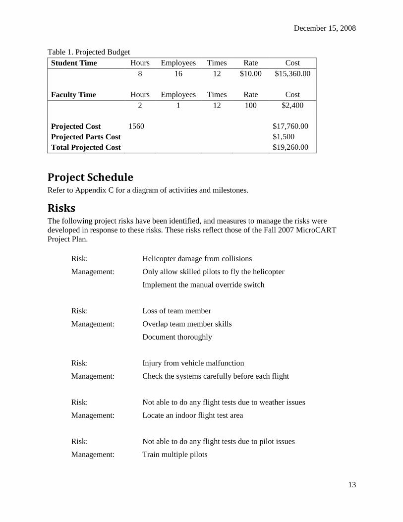
Resource Requirements Consulting costs were calculated on the basis of a standard labor rate for the course, $10.
Projected costs are shown in Table 1. In addition to man hour costs, an additional $1,500 will be
estimated for unforeseen parts needed for repairs and enhancements on the helicopter that may
arise.
December 15, 2008
13
Table 1. Projected Budget
Student Time Hours Employees Times Rate Cost
8 16 12 $10.00 $15,360.00
Faculty Time
Hours
Employees
Times
Rate
Cost
2 1 12 100 $2,400
Projected Cost
Projected Parts Cost
Total Projected Cost
1560
$17,760.00
$1,500
$19,260.00
Project Schedule Refer to Appendix C for a diagram of activities and milestones.
Risks The following project risks have been identified, and measures to manage the risks were
developed in response to these risks. These risks reflect those of the Fall 2007 MicroCART
Project Plan.
Risk: Helicopter damage from collisions
Management: Only allow skilled pilots to fly the helicopter
Implement the manual override switch
Risk: Loss of team member
Management: Overlap team member skills
Document thoroughly
Risk: Injury from vehicle malfunction
Management: Check the systems carefully before each flight
Risk: Not able to do any flight tests due to weather issues
Management: Locate an indoor flight test area
Risk: Not able to do any flight tests due to pilot issues
Management: Train multiple pilots

December 15, 2008
14
Risk: Equipment Hardware failures
Management: Implement vibration isolation on all electronic components
Keep funds available for equipment replacement
Make sure the components and connections are correct before
powering components or conducting a flight test
December 15, 2008
15
DESIGN DOCUMENT
Ground Station
Ground Station Software Ground station software loads waypoints for the helicopter prior to flight and displays real-time
system status of the helicopter, specifically: its altitude, heading, positioning, and location. Most
of the ground station has been implemented and it is close to being completed. Work is still
ongoing for communication and advanced flight data logs. The term of our project, spring 2008
through fall 2008, will mostly involve testing and fixing any bugs that arise during multiple
flight tests. One new feature to the ground station was created this semester, which aided in
testing the ground station and flight control packet communication. This new feature is called
the Packet Tester is described below.
Packet Tester Communication problems arose when integrating the Java ground station and flight control
software. These problems included not sending packets correctly, not receiving packets
correctly, and not properly reading incoming data from the serial port. Both ground station and
flight control were not receiving accurate information when communicating with each other. To
make these errors easier to detect and fix, a packet tester program was created that sends each
packet type to the flight control software individually. The packet tester program will print out
the exact data sent, so it can be compared to data received by flight control software.
Input Specification 1. The user shall input the data that they would like to put in the packet.
2. The user shall decide which packet to send to the flight control software.
Output Specification
1. The program shall send the user-selected packet with the user entered data to the flight
control software.
2. The program shall output the packet information that was sent so the information can be
compared with data the flight control receives.
User Interface Specification
1. The user interface shall show a list of all available packet types to send.
2. The user interface shall have a button for every packet type that will send the specified
packet to the flight control software.
3. The user interface shall provide an easy and safe way to change a specified packet‟s data
through the use predefined check and text boxes.
December 15, 2008
16
Software Specification 1. The program shall use the serial communication class used by the ground station to send
the state packet to the flight control software.
2. The program shall use the “state packet type” classes used by the ground station to create
the packets.
3. The program shall run and send packets as selected indefinitely until the user closes the
program.
Functions
- void main()
o launches program and calls PacketTest() method
- public PacketTest()
o initializes program by calling below functions
- initComponents()
o initializes user interface and button actionPerformed() functions
- initMyVariables()
o sets up serial communication and packet creation
Final Status Over the course of this semester the communication capabilities, as well as the information
handling capabilities, were enhanced on the Ground Station (GS). At the beginning of this
semester the helicopter was not receiving most of the packets sent by the GS, making
communication issues of the highest priority. Our secondary priority was to improve the
information handling capability to allow for easier access to and better interpretation of data.
We found that the helicopter was using too much of its resources to send packets, and as a result,
was unable to process most of the incoming packets. To solve this problem, we reduced the rate
of packets being sent from the helicopter. Lab tests confirmed that packets could be sent
successfully from the GS once this rate was reduced. The functionality to manage the rate at
which the helicopter sends packets was added to the GS in the form of a menu option. The menu
option pulls up a dialogue box giving the user an option to set or change the rate at which
packets are being sent. Currently, the user can use this menu option to adjust the rate for
receiving State packets and Dynamic PID packets.
A new Trim tab was added to the GS. This feature allows the user to set/adjust the trim settings
directly from the GS before, during, or in between flights. Prior to this semester, these values
were hard coded and did not extend the same flexibility needed to adjust trim settings
dynamically. The user can adjust the trim settings by selecting the “Servo Trim” tab; enter the
individual trim values for each servo, then click the send button to send the packet to the
helicopter.
The GS underwent improvements to the information handling capability to allow for easier
access to and better interpretation of data. The data logging format was changed from a simple
.txt file to a .csv file. With this format, the data log can be opened directly from any spreadsheet
program. An indicator was added to the data log to indicate whether the data was logged during
December 15, 2008
17
computer controlled flight or whether it was logged during manual controlled flight. The user
must click the “Manual / Computer Control” button, located on the “Home” tab, to change the
log indicator. New Graphing capabilities were also added to the GS. The user can tailor the
graph to include a specific data series, single or multiple plots, and has the option to label and
save plots. This graph can be selected as a menu option and is intended for instant feedback
during or immediately after flight tests.
Sensors
Altimeter
Input Specification
The primary input to the entire altimeter subsystem is the atmospheric pressure.
Output Specification The primary output is the altitude calculated from the measured atmospheric pressure. The
altitude output is of type float.
User Interface Specification
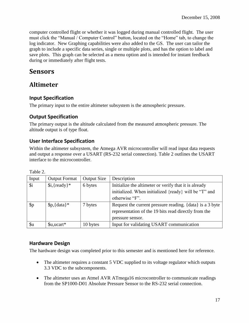
Within the altimeter subsystem, the Atmega AVR microcontroller will read input data requests
and output a response over a USART (RS-232 serial connection). Table 2 outlines the USART
interface to the microcontroller.
Table 2.
Input Output Format Output Size Description
$i $i,{ready}* 6 bytes Initialize the altimeter or verify that it is already
initialized. When initialized {ready} will be “T” and
otherwise “F”.
$p $p,{data}* 7 bytes Request the current pressure reading. {data} is a 3 byte
representation of the 19 bits read directly from the
pressure sensor.
$u $u,ucart* 10 bytes Input for validating USART communication
Hardware Design The hardware design was completed prior to this semester and is mentioned here for reference.
The altimeter requires a constant 5 VDC supplied to its voltage regulator which outputs
3.3 VDC to the subcomponents.
The altimeter uses an Atmel AVR ATmega16 microcontroller to communicate readings
from the SP1000-D01 Absolute Pressure Sensor to the RS-232 serial connection.
December 15, 2008
18
Atmel AVR ATmega16 8-bit Microcontroller
The AVR communicates over the RS-232 serial connection using the Serial USART.
The AVR communicates with the SCP1000-D01 using the SPI bus.
SCP1000-D01 Absolute Pressure Sensor
The SCP1000 operates at supply voltages from 2.4 to 3.3 VDC with a very low current
draws (typically <25uA).
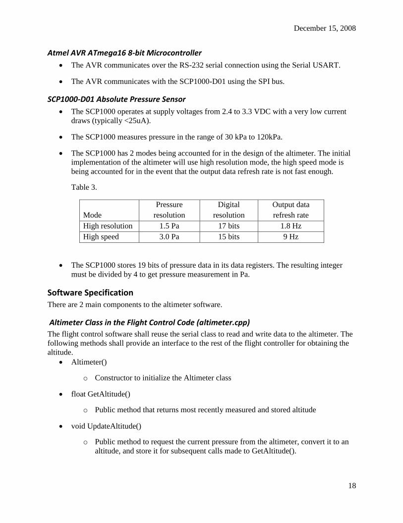
The SCP1000 measures pressure in the range of 30 kPa to 120kPa.
The SCP1000 has 2 modes being accounted for in the design of the altimeter. The initial
implementation of the altimeter will use high resolution mode, the high speed mode is
being accounted for in the event that the output data refresh rate is not fast enough.
Table 3.
Mode
Pressure
resolution
Digital
resolution
Output data
refresh rate
High resolution 1.5 Pa 17 bits 1.8 Hz
High speed 3.0 Pa 15 bits 9 Hz
The SCP1000 stores 19 bits of pressure data in its data registers. The resulting integer
must be divided by 4 to get pressure measurement in Pa.
Software Specification There are 2 main components to the altimeter software.
Altimeter Class in the Flight Control Code (altimeter.cpp)
The flight control software shall reuse the serial class to read and write data to the altimeter. The
following methods shall provide an interface to the rest of the flight controller for obtaining the
altitude.
Altimeter()
o Constructor to initialize the Altimeter class
float GetAltitude()
o Public method that returns most recently measured and stored altitude
void UpdateAltitude()
o Public method to request the current pressure from the altimeter, convert it to an
altitude, and store it for subsequent calls made to GetAltitude().
December 15, 2008
19
Altimeter Microcontroller Code (altimeter_uc.c)
The following methods allow the Altimeter class of the flight control code to retrieve readings
from the pressure sensor.
void main()
o Initializes both the microcontroller and pressure sensor. Then it loops indefinitely
taking messages from sensorRead() and determining the proper course of action.
void initAtmega()
o Initializes the Atmel AVR microcontroller.
void initPressureSensor()
o Initializes the SCP1000 pressure sensor.
char* getPressure()
o Retrieves pressure reading from the pressure sensor. This function may be called
any time during normal operation and will wait until the sensor is ready.
char* readRS232()
o Retrieves and returns a message from the RS-232 serial port. This function will
wait until the port is ready and reads until a null character is found or the buffer is
full.
void writeRS232(char*)
o Writes data over the RS-232 serial port one byte at a time until the entire message
has been sent.
char usartRead8()
o Reads and returns 8 bits of data from the RS-232 serial port (USART).
void usartWrite8(char data)
o Writes 8 bits of data to the RS-232 serial port (USART).
void sensorWrite8(const SensorAddr_t address, const char data)
o Writes 8 bits of data to the address specified of the pressure sensor (SPI).
char sensorRead8(const SensorAddr_t address)
o Reads and returns 8 bits of data from the address specified of the pressure sensor
(SPI).
See Appendix A, Figure 5 for a sequence diagram of the altimeter pressure read request.
December 15, 2008
20
Test Specification Test USART communication by connecting the altimeter to a terminal on a laptop and
sending the $u message and verifying the altimeter responds with $u,ucart*
Test the altimeter for correct and calibrated pressure readings independent of the
helicopter and flight control software. Connect the altimeter to a terminal on a laptop and
sending the $p message several times at various altitudes. Verify the pressure
corresponds to the expected pressure at those altitudes.
Integrate the altimeter into the helicopter, and verify that the ground station receives the
correct altitude from the altimeter when the helicopter is at various in-lab altitudes. Also
verify that flight control can run without crashing when the altimeter enable.
Final Status The hardware for the altimeter has been verified and the first semester team is making progress
on the microcontroller software.
Compass
Input Specification The magnetic heading is the input to the compass which can be split into x, y, and z components.
The compass software also uses the IMU pitch and roll as input.
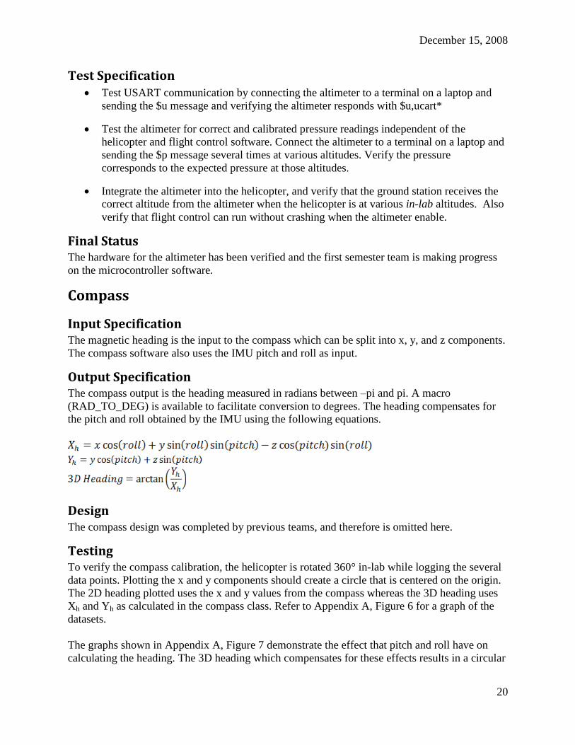
Output Specification The compass output is the heading measured in radians between –pi and pi. A macro
(RAD_TO_DEG) is available to facilitate conversion to degrees. The heading compensates for
the pitch and roll obtained by the IMU using the following equations.
Design The compass design was completed by previous teams, and therefore is omitted here.
Testing To verify the compass calibration, the helicopter is rotated 360° in-lab while logging the several
data points. Plotting the x and y components should create a circle that is centered on the origin.
The 2D heading plotted uses the x and y values from the compass whereas the 3D heading uses
Xh and Yh as calculated in the compass class. Refer to Appendix A, Figure 6 for a graph of the
datasets.
The graphs shown in Appendix A, Figure 7 demonstrate the effect that pitch and roll have on
calculating the heading. The 3D heading which compensates for these effects results in a circular
December 15, 2008
21
plot centered on the origin indicating that the calibration holds and a reliable heading can be
calculated.
However, these in-lab results do not reflect the compass behavior in flight. The presence of noise
has a large affect on the compass. Without access to the same set of data during flight, we rely on
merely the final calculated heading. Under the condition that our pilot maintains the helicopter in
the air with a near constant heading, we expect that a plot of that heading should be nearly a
constant line. The graph in Appendix A, Figure 8 shows the actual data that we experienced
during the flight test.
Final Status The compass behaves as expected in the laboratory but is set back by noise when the engine is
running. As a team we were able to analyze the compass data in real time and make the decision
the compass was not reliable enough in-flight to test independent autonomous hove on the yaw
servo.
Sonar
Input Specification The distance from the sonar transducer to the ground or some other object is the input to the
sonar.
Output Specification The sonar output is the distance above the ground or another object, measured in feet, that is
calculated from the voltage that is output by the sonar transducer.
Design The sonar design was completed by previous teams, and therefore is omitted here.
Testing Some initial in-flight data suggested that our sonar was not functioning to the originally specified
20 feet. A simple experiment was designed to test the range of the sonar by turning the helicopter
on its side and moving a large platform away from it in 1-foot increments. The graph of this data,
shown in Appendix A, Figure 9, suggests that the sonar is only reliable through 16 feet.
While the details of filtering are not explained here, the plot shown in Appendix A, Figure 10,
obtained in the same way after enabling filtering shows that sonar distance can be determined to
18 or 19 feet.
Final Status The sonar has been verified to be reliable from 6 inches to about 18 feet in the laboratory when
the filtering is enabled. The next steps for the sonar should be to verify that the sonar‟s calculated
distance maps to the ADC values determined in this data (the current software model incorrectly
assumes 20 feet occurs at an ADC value of about 1024). Finally a plot of sonar data in-flight is
needed to prove its behavior under flight conditions. Since the sonar is not critical to our

December 15, 2008
22
immediate goals, this work has been deferred for more pressing functionality like the compass
and altimeter.
GPS
Input Specification The physical location of the helicopter is the input to the GPS.
Output Specification The GPS outputs the x, y, and z components of the helicopter‟s location as determined by GPS
satellites.
Design The GPS design was completed by previous teams, and therefore is omitted here.
Final Status The GPS software is believed to be nearly complete. However, the GPS receiver is unable to get
a satellite fix when connected to the helicopter. It is able to obtain a fix when connected to a
laptop. Attempts to troubleshoot this problem have suggested that the compass may be acting as
a source of noise to the GPS.
Filtering The Xcell-60 helicopter presents an unfavorable environment for sensitive electronic devices.
Electromagnetic radiation from the helicopter‟s ignition system can introduce noise, or unwanted
frequency content, into signals coming from the various sensors mounted on the helicopter.
Mechanical vibration can also introduce noise into signals coming from sensors that are sensitive
to motion, such as the Inertial Measurement Unit (IMU). Therefore, filtering of sensor data is
necessary to remove unwanted noise, while still retaining as much useful information as
possible.
The eventual goal for the MicroCART project is to use Kalman filtering for all sensor data.
However, due to the complexity of the Kalman filter and its implementation, along with the
pressing need for filtering of sensor data, a phased approach will be used – initially, filtering will
be implemented using simple frequency-domain lowpass filters, which have the advantage of
being easy to design, implement, and understand. Later, lowpass filters will be replaced by a
Kalman filter.
Digital Butterworth Lowpass Filter A digital Butterworth lowpass filter has advantages over other types of digital filters in that it has
no ripple in the passband, and the filter coefficients can be adjusted such that the gain of the
Butterworth filter is never greater than unity.
The design used was a C++ class for a generic Nth order digital Butterworth filter, which is

December 15, 2008
23
characterized by the transfer function N
N
N
N
za++za+a
zb++zb+b=H(z)
1
10
1
10 . Since the filter class is
generic, it can be easily reused, with different parameters, for different sensors.
Input Specification The filter accepts a single “channel” of data from a sensor as input.
Output Specification
The filter outputs a filtered version of the sensor data, with unwanted high frequency content
attenuated.
Software Specification
Class Diagram
See Appendix A, Figure 11.
Module Specification
Data Structures
The ButterworthFilter class contains the following private attributes:
int order
o An integer used to store the length, or order, of the filter
vector<float> aCoeffs
o A vector of floats containing the „a‟ coefficients
vector<float> bCoeffs
o A vector of floats containing the „b‟ coefficients
vector<float> inDelayLine
o A vector of floats that stores previous inputs
vector<float> outDelayLine
o A vector of floats that stores previous outputs
Methods
The ButterworthFilter class defines the following public methods:
December 15, 2008
24
ButterworthFilter(int N, vector<float> a, vector<float> b)
This constructor method takes the order N, along with vectors containing the coefficients as
arguments. The constructor allocates copies the contents of the a and b vectors to its own internal
data members, and initializes the input and output delay lines to zero.
~ButterworthFilter()
The destructor method deallocates the coefficient and delay line arrays.
float runFilter(float input)
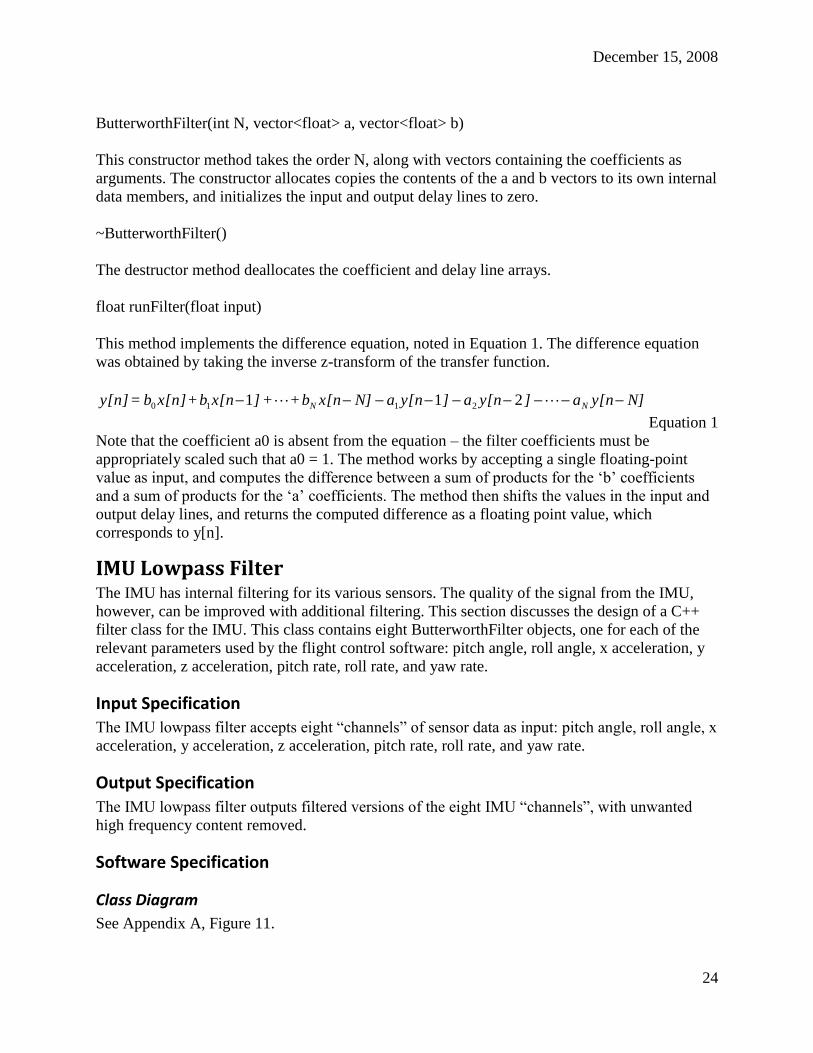
This method implements the difference equation, noted in Equation 1. The difference equation
was obtained by taking the inverse z-transform of the transfer function.
N]y[na]y[na]y[naN]x[nb++]x[nb+x[n]b=y[n] NN 211 2110
Equation 1
Note that the coefficient a0 is absent from the equation – the filter coefficients must be
appropriately scaled such that a0 = 1. The method works by accepting a single floating-point
value as input, and computes the difference between a sum of products for the „b‟ coefficients
and a sum of products for the „a‟ coefficients. The method then shifts the values in the input and
output delay lines, and returns the computed difference as a floating point value, which
corresponds to y[n].
IMU Lowpass Filter The IMU has internal filtering for its various sensors. The quality of the signal from the IMU,
however, can be improved with additional filtering. This section discusses the design of a C++
filter class for the IMU. This class contains eight ButterworthFilter objects, one for each of the
relevant parameters used by the flight control software: pitch angle, roll angle, x acceleration, y
acceleration, z acceleration, pitch rate, roll rate, and yaw rate.
Input Specification The IMU lowpass filter accepts eight “channels” of sensor data as input: pitch angle, roll angle, x
acceleration, y acceleration, z acceleration, pitch rate, roll rate, and yaw rate.
Output Specification
The IMU lowpass filter outputs filtered versions of the eight IMU “channels”, with unwanted
high frequency content removed.
Software Specification
Class Diagram
See Appendix A, Figure 11.

December 15, 2008
25
Module Specification
Data Structures
The IMU_LPFilter class contains the following private attributes:
ButterworthFilter *pitchAngleFilter
ButterworthFilter *rollAngleFilter
ButterworthFilter *xAccelFilter
ButterworthFilter *yAccelFilter
ButterworthFilter *zAccelFilter
ButterworthFilter *pitchRateFilter
ButterworthFilter *yawRateFilter
ButterworthFilter *rollRateFilter
Each of these private attributes is a pointer to a ButterworthFilter object for each flight parameter
tracked by the IMU.
Methods
The IMU_LPFilter class defines the following public methods:
IMU_LPFilter()
This constructor method dynamically allocates the ButterworthFilter objects and initializes the
filter parameters for each individual ButterworthFilterd object contained in the class.
~IMU_LPFilter()
This destructor method deallocates the ButterworthFilter objects.
vector<float> runFilter(vector<float> inputs &)
This method accepts a vector of floating point values corresponding to pitch and roll angles,
accelerations, and angular rates. It routes each input to its corresponding filter object and calls
the runFilter() method on each object. The results are returned as a vector of floats.
Compass Lowpass Filter The compass measured a 3D heading, with x, y, and z values. Because the compass is
particularly susceptible to electromagnetic noise, filtering is necessary to get a reliable heading.
December 15, 2008
26
Input Specification The compass lowpass filter accepts a vector of three floating point values, for the x, y, and z
measurements made by the compass.
Output Specification
The compass lowpass filter outputs a vector of three floating point values, with high-frequency
information beyond a cutoff point removed from each signal.
Software Specification
Class Diagram
See Appendix A, Figure 11.
Module Specification
Data Structures
The IMU_LPFilter class contains the following private attributes:
ButterworthFilter *xFilter
ButterworthFilter *yFilter
ButterworthFilter *zFilter
Each of these private attributes is a pointer to a ButterworthFilter object for each axis measured
by the compass.
Methods
The Compass_LPFilter class defines the following public methods:
Compass_LPFilter()
This constructor method dynamically allocates the ButterworthFilter objects and initializes the
filter parameters retrieved from the XML configuration file for each individual ButterworthFilter
object contained in the class.
~Compass_LPFilter()
This destructor method deallocates the ButterworthFilter objects.
vector<float> runFilter(vector<float> inputs &)
This method accepts an array of floating point values corresponding to the x, y, and z values
measured by the compass, runs one iteration of the filter, and outputs a vector containing the
filtered x, y, and z values.

December 15, 2008
27
Integration Appendix A, Figure 12 shows how the filters are implemented in the system. IMU_LPFilter
resides in Imu.cpp and takes as input pitch and roll angles, x, y, z accelerations, and pitch, roll,
and yaw rates. These values are each individually filtered by a ButterworthFilter object, and
then sent out to Imu.cpp, for calibration and processing. The individual ButterworthFilter in
Sonar.cpp filters the output voltage from the I/O board on the sonar, and outputs it back to the
Sonar object. The Compass_LPFilter resides in Compass.cpp and takes and input the x, y and z
values from the physical compass. Each channel of data is filtered and output to the compass
object.
Each sensor object has a global variable that is used in an if statement to enable or disable the
filter. This filter enable is globally set, all filters are either enabled or disabled. Additionally the
filter enable is settable from the ground station to all for easy collection of both filtered and
unfiltered data.
Each filter uses a single set of equation coefficients for all ButterworthFilter objects it contains.
These coefficients are stored in the configuration XML file that is parsed at flight control start
up. At start up each set of a and b coefficients is parsed from the file and used to initialize each
corresponding filter object.
The XML parser was modified to parse out an array of values given a single tag. This is
preferable to calling the parser for each individual coefficient for every filter. The parser had a
method available to find every instance of a tag at the lowest level, but it was not fully
implemented. Higher level methods were created to retrieve an array of strings or array of
floating point numbers that implemented this lower level method in the parser.
GetItemSet(string, string) is used to read out the array of strings, GetFloatSet(string,string) calls
GetItemSet and converts strings to floating point values. See Appendix A, Figure 13.
Testing Testing the C++ ButterworthFilter class for correctness involves measuring its impulse response.
This is accomplished via a simple C++ test program that reads in a vector containing a unit
impulse from a file, running that data through the filter (for some set of filter parameters), with
repeated calls to the runFilter() method, and recording the results in a second file. Similarly, that
same unit impulse is run through a simulated filter (using the same paramaters as the test code)
in Matlab using the filter() function. The measured impulse response from the test code is then
compared with the response of the simulated filter. If the two are in agreement, then the filter
code is known to be behaving correctly.
As seen in Appendix A, Figure 14 the measured and simulated impulse responses are nearly
identical. The small error present, which is on the order of 10e-7 and therefore negligible, is due
to differences in precision between the filter code and Matlab. Whereas the filter code uses single
precision (32-bit) floating point numbers in its calculations, Matlab by default uses double
precision (64-bit) floats for all calculations.
December 15, 2008
28
Final Status Filtering is fully implemented for the IMU, Compass, and Sonar, and these sensors have each
been characterized and assigned appropriate filter coefficients. In addition, the ButterworthFilter
class has been tested for correctness.
Flight Control Software The flight control software controls the all aspects of the autonomous flight of the helicopter
including the communication between the ground station and the helicopter, reading data from
the sensors, and controlling the movement of the servos. Currently the flight control software is
very close to being completed. This semester has mainly focused on finding and fixing bugs
through lab tests of the system. A few tools were designed this semester to aid in component
testing the software. A tool was created to test the communication between the software and the
ground station as well as a tool to test the communication between the software and the servo
controller.
Ground Station Communication Tester As we were integrating the Java based ground station, some problems arose in the
communication stack that was causing unexpected data to be received by the ground station.
Because of the amount and uncertainty of the data that was being sent by the helicopter, it made
it difficult to debug whether the helicopter was sending the correct data or if the ground station
was misinterpreting the data that it was receiving. It was decided to create a utility that could be
used to send packets of controlled information from the helicopter to the ground station.
Input Specification 1. The utility shall be started by execution from a remote terminal on the helicopter.
Output Specification
1. The utility shall output state packets through the RF-modem on the helicopter.
2. The utility shall first output a state packet with all fields 0.
3. The utility shall second output a state packet with alternative 1s and 0s in the fields.
4. The utility shall lastly output a state packet with ascending values from 1 to 19 in the
fields.
User Interface Specification After the utility is started, no further interaction from the user is required. As the user is not
required to provide any input, there is no defined user interface.
Software Specification
1. The utility shall use the state packet struct as defined by the flight control software.
2. The utility shall use the serial class used by the flight control software to send the state

December 15, 2008
29
packets.
3. The utility shall send the three state packets as defined in the output specifications upon
starting and then exit.
Functions
int main()
The main control loop of the utility.
Provides all the functionality of the utility.
Servo Controller Tester As we were integrating the manual override we discovered that our flight control software was
having a difficult time communicating with the servo controller. While this turned out not to be
an issue with the flight control software, we decided that it would be a good idea to create a tool
that could be used to test the flight control software's interaction with the servo controller
independently from the rest of the system. This would prove useful not only in the debugging of
the servo controller, but also as a preflight test of the servos and servo controller.
Input Specification
1. The user shall input which of the 5 servos to test.
2. The user shall have the option to test all of the servos at once.
Output Specification 1. The utility shall run the user defined servo through its full range.
User Interface Specification
1. The user interface shall ask the user which servo he wishes to test.
2. The user interface shall display the progress of the test to the user.
Software Specification 1. The utility shall use the servo class used by the flight control software to control the
servos.
2. The utility shall use the Servo::setMotorPosition() function of the servo controller class to
run the servo through it's full range, from 0 to 255.
Functions
int main()
Prompts for user input
Starts the servo test
void testServo(Servo *)
Runs the full range test of the servo passed in as argument 1.
Final Status The major accomplishments for the flight control software were the addition of customization

December 15, 2008
30
that solved some problems that we were experiencing at the beginning of year. The two major
problems were a communications problem that was causing the ground station to not be able to
send information to the flight control software and a lack of ability to update the servo trim
without recompiling.
The communications issue was determined to be caused by our helicopter jamming the
communication channel with too many packets. The issue was worsened when the engine was
on, as this caused a greater number of packets to become corrupted, which our RF modem would
then detect and retransmit. This would cause even more congestion on the channel. The flight
control software was modified to accept communication rates from the ground station. This
allowed us to lower communication rates in hopes of clearing the channel if it were to become
congested.
In the last flight test before we came on the project, the team had issues with the helicopter
drifting while trying to hover. This was determined to be due to the servo trim setting that the
pilot had set on the manual controller did not match the trim that the flight control software was
set at. The trim was a setting in our configuration XML which required access to the helicopter
in a way that we don't have on the field. Therefore, the flight control software was modified to
accept servo trim values from the ground station and update. This allowed for greater flexibility
during flight tests to change the trim on the field.
Manual Override
Functional Requirements FR1: The manual override shall allow control of the helicopter via remote control at the
beginning stages of this project.
FR2: The manual override shall allow control of the helicopter via remote control in emergency
situations once the project is finished
FR3: The manual override shall use the designated channel 7 on the receiver for the remote
control.
FR4: The manual override shall switch between the appropriate inputs, either manual or
computer controlled, to drive all of the servos depending on the signal received on channel 7
Design Knowing we had to choose between two different signals, obviously a switch was needed. The
type of switch we chose was a relay. This relay is driven by the channel 7 input. There will need
to be a unique relay for each of the servos. The relay‟s common port shall be connected to the
servo. This will be the output of our circuit. The normally open port will be connected to receive
input from the computer. The computer must first output to the servo controller, and then the
servo controller‟s output pins directly connect to the normally open port of the relay. Lastly, the
normally closed port of the relay will be receiving input from the remote control receiver. We
chose this setup because if the relay fails, we still want to be able to control it manually and not
have to rely on the computer control.
December 15, 2008
31
Input Specification 1. The circuit will receive input from a remote control being run manually on the ground.
A.) If channel 7 is switched on, the input that will drive the servos will come from the
remote control, as normal.
B.) If channel 7 is toggled to the middle position, the input driving the servos will
ultimately come from the computer, on COM port 3, via a Pontech servo control
board.
Output Specification
1. The output of the circuit will drive each of the servos with appropriate input, from either
the RC receiver, or from the Pontech servo controller.
Hardware Specification
Components
The servo controller is made by Pontech, and the model number is SV203. This is a
common servo controller and is compatible with the servos we already have. The relay
used is an RCATS RC-100X. We chose this relay because we already had one set up as
the kill switch. Using similar components minimizes the complexity of the model.
Diagram
See Appendix A, Figure 15.
Final Status
At the start of the semester we had a working manual override with a successful flight test on a
single servo. We then duplicated the circuit to incorporate a second servo. After a successful in
lab test of the two channels, roll and pitch, we ground tested with the helicopter engine on and
found there was some major noise issues. Back in the lab we isolated the problem and found that
the noise was causing interference in the input signal that switches between the manual control
and computer control. In an attempt to fix this problem, we were able to use a feature on our
Spektrum transmitter to adjust the duty cycle of the channel 7 signal, which is what we were
using to toggle between the two inputs. We were able to minimize the unwanted switching by
changing this duty cycle, however we concluded that it was too unreliable and would have to be
reconfigured with the addition or any modifications to the manual override circuit. Facing that
problem, we decided a new manual override was needed to insure a reliable system.
The new manual override we decided upon was one from ElectroDynamics. After some market
research we concluded this was an excellent choice as it has a great track record with multiple
successful NASA unmanned aerial vehicle flight missions. We installed this circuit on both the
roll and pitch servos. After successful in lab tests as well as successful ground tests, we were
able to safely and reliably fly our helicopter using our new manual override circuit. The reason
this circuit works compared to our old one is that it uses an optical signal which is much more
reliable for our noise problems than the old electromechanical switching of the old RCATS
relay. See Appendix A, Figure 16.

December 15, 2008
32
Our new manual override has a Watchdog safeguard. This feature needs a pulse width modulated
signal of less than two seconds between edges in order to use the computer controlled signal. If it
does not receive this signal or its frequency is outside the desired range, the circuit will default to
using the manual control signal. We were able to use an extra channel on our Pontech servo
controller to satisfy this watchdog, as our servo controller produces a signal similar to the one
below, which falls well within the required range of less than two seconds. The figure shows the
max and min signals our servo controller produces that correspond to the servos moving a full 90
and -90 degrees. See Appendix A, Figure 17.
Earned Value Analysis
Ground Station Work Scheduled: Work Performed: Mike: 45 hrs Mike: 53.5 hrs
Dave: 45 hrs Dave: 41.5 hrs
Total: 90 hrs Total: 95.0 hrs
Budgeted Cost of Work Scheduled(BCWS): 90 hrs * $10/hr = $900
Actual Cost of Work Performed(ACWP): 95 hrs * $10/hr = $950
Budgeted Cost of Work Performed(BCWP): (95/90)percent * 90 hrs * $10/hr = $950
Cost Variance: (CV=BCWP-ACWP) $950 - $950 = $0
Cost Performance Index: (CPI=BCWP/ACWP) $950/$950 = 1
Schedule Variance: (SV=BCWP-BCWS) $950 - $900 = $50
Schedule Performance Index: (SPI=BCWP/BCWS) $950/$900 = 1.056
Sensors Work Scheduled: Work Performed: Anthony: 48 hrs Anthony: 55 hrs
Budgeted Cost of Work Scheduled(BCWS): 48 hrs * $10/hr = $480
Actual Cost of Work Performed(ACWP): 55 hrs * $10/hr = $550
Budgeted Cost of Work Performed(BCWP): (55/90)percent * 90 hrs * $10/hr = $550
Cost Variance: (CV=BCWP-ACWP) $550 - $550 = $0
Cost Performance Index: (CPI=BCWP/ACWP) 1045/1045 = 1
Schedule Variance: (SV=BCWP-BCWS) $550 - $480 = $70
Schedule Performance Index: (SPI=BCWP/BCWS) $550/$480 = 1.15
Filtering Work Scheduled: Work Performed: Karl: 48 hrs Karl: 31.5 hrs
Matt: 48 hrs Matt: 35 hrs
Total: 96 hrs Total: 66.5 hrs
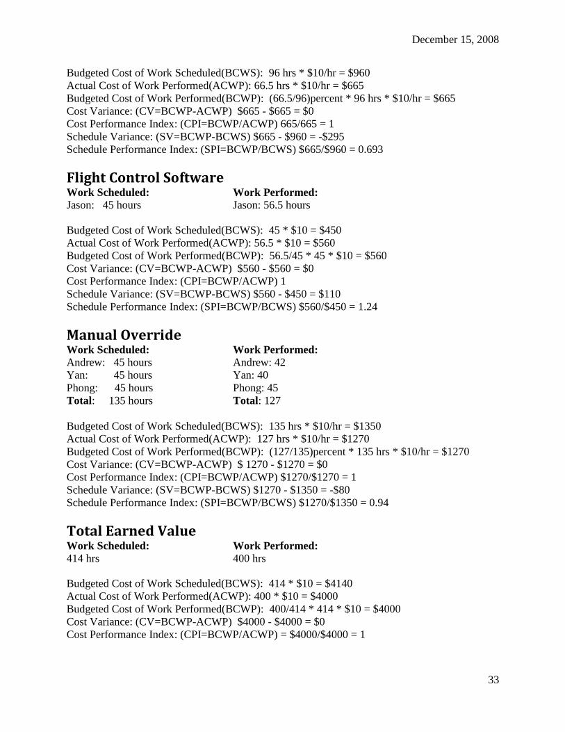
December 15, 2008
33
Budgeted Cost of Work Scheduled(BCWS): 96 hrs * $10/hr = $960
Actual Cost of Work Performed(ACWP): 66.5 hrs * $10/hr = $665
Budgeted Cost of Work Performed(BCWP): (66.5/96)percent * 96 hrs * $10/hr = $665
Cost Variance: (CV=BCWP-ACWP) $665 - $665 = $0
Cost Performance Index: (CPI=BCWP/ACWP) 665/665 = 1
Schedule Variance: (SV=BCWP-BCWS) $665 - $960 = -$295
Schedule Performance Index: (SPI=BCWP/BCWS) $665/$960 = 0.693
Flight Control Software Work Scheduled: Work Performed: Jason: 45 hours Jason: 56.5 hours
Budgeted Cost of Work Scheduled(BCWS): 45 * $10 = $450
Actual Cost of Work Performed(ACWP): 56.5 * $10 = $560
Budgeted Cost of Work Performed(BCWP): 56.5/45 * 45 * $10 = $560
Cost Variance: (CV=BCWP-ACWP) $560 - $560 = $0
Cost Performance Index: (CPI=BCWP/ACWP) 1
Schedule Variance: (SV=BCWP-BCWS) $560 - $450 = $110
Schedule Performance Index: (SPI=BCWP/BCWS) $560/$450 = 1.24
Manual Override Work Scheduled: Work Performed: Andrew: 45 hours Andrew: 42
Yan: 45 hours Yan: 40
Phong: 45 hours Phong: 45
Total: 135 hours Total: 127
Budgeted Cost of Work Scheduled(BCWS): 135 hrs * $10/hr = $1350
Actual Cost of Work Performed(ACWP): 127 hrs * $10/hr = $1270
Budgeted Cost of Work Performed(BCWP): (127/135)percent * 135 hrs * $10/hr = $1270
Cost Variance: (CV=BCWP-ACWP) $ 1270 - $1270 = $0
Cost Performance Index: (CPI=BCWP/ACWP) $1270/$1270 = 1
Schedule Variance: (SV=BCWP-BCWS) $1270 - $1350 = -$80
Schedule Performance Index: (SPI=BCWP/BCWS) $1270/$1350 = 0.94
Total Earned Value Work Scheduled: Work Performed: 414 hrs 400 hrs
Budgeted Cost of Work Scheduled(BCWS): 414 * $10 = $4140
Actual Cost of Work Performed(ACWP): 400 * $10 = $4000
Budgeted Cost of Work Performed(BCWP): 400/414 * 414 * $10 = $4000
Cost Variance: (CV=BCWP-ACWP) $4000 - $4000 = $0
Cost Performance Index: (CPI=BCWP/ACWP) = $4000/$4000 = 1

December 15, 2008
34
Schedule Variance: (SV=BCWP-BCWS) $4000 - $4140 = -$140
Schedule Performance Index: (SPI=BCWP/BCWS) $4000/$4140 = 0.96
Lessons Learned The first major lesson that we learned during this semester was the fact of noise. Our system that
we tested in the lab is a completely different system that was tested during a ground test or a
flight test, this is due to the engine running. While the engine running, it is a major noise source.
With electrical noise, physical vibration, and electromagnetic noise the engine presents a
significant challenge to our system. Learning to foresee these interactions in a lab setting as well
as knowing that getting the system working in the lab was not an indication that it would work
when the helicopter was flying. These are only a few consequences of the noise issues.
The second lesson that we learned was that we could not be overspecialized in any one area of
the helicopter. Our system is very complex with many components and interact very closely with
each other. When one gets too narrow sighted on problems that come up, solutions will be
developed that are not ideal or will not actually solve the problem.
The third lesson that we learned was to prioritize our tasks based on our goals. We accomplished
a lot during the semester, but progress was made in lower-priority areas that were not directly
related to our goals. These resources should have been reallocated to parts of our system that
were more critical to our project's success.
Conclusions While we fell short of implementing independent autonomous hover on all servo channels, we
were still able to make significant progress on the project. We weren‟t able to attempt hovers on
yaw, throttle, or collective due to problems with the compass and the unfinished state of the
altimeter, respectively. However, we expect these issues to be addressed quickly by future teams,
after which the project can move forward to the movement and navigation phase.
References International Aerial Robotics Competition(2008) RULES FOR THE CURRENT
INTERNATIONAL AERIAL ROBOTICS COMPETITION MISSION. Retrieved February 21,
2008, from http://avdil.gtri.gatech.edu/AUVS/CurrentIARC/200xCollegiateRules.html.
Weber B, Nguyen M, Sanfilippo P, Peyton M, Laird A, Si Jun Sung,Van Auken E, Brokman A.
(Fall 2007). Micro-Cart Fall 2007 Project Plan. Iowa State University, Department of Electrical
and Computer Engineering.
Wikipedia(2003, September 10). International Aerial Robotics Competition. Retrieve February
21, 2008, from http://en.wikipedia.org/wiki/International_Aerial_Robotics_Competition.
December 15, 2008
35
Agreement of Compliance
Faculty Advisor
XDr. Greg Smith
Electrical and Computer Engineering Program ...
Team Members
Matt Beecher X
Drew Crawford X
Mike Dent X
Phong Deo X
Jason Funk X
Anthony Nowell X
Karl Svec X
Dave Zajicek X
Yan Zhang X

December 15, 2008
36
Appendix A: Figures
Figure 1: Concept Sketch
Figure 2: System Block Diagram
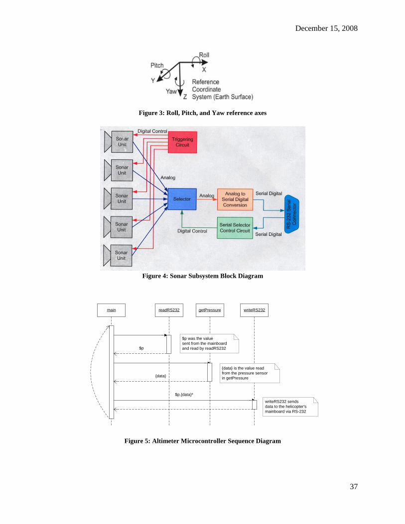
December 15, 2008
37
Figure 3: Roll, Pitch, and Yaw reference axes
Figure 4: Sonar Subsystem Block Diagram
main getPressurereadRS232 writeRS232
$p
{data}
$p,{data}*
writeRS232 sends
data to the helicopter's
mainboard via RS-232
$p was the value
sent from the mainboard
and read by readRS232
{data} is the value read
from the pressure sensor
in getPressure
Figure 5: Altimeter Microcontroller Sequence Diagram

December 15, 2008
38
Figure 6: 2D and 3D headings captured on a level surface
Figure 7: 2D and 3D headings with 15 degree pitch and roll
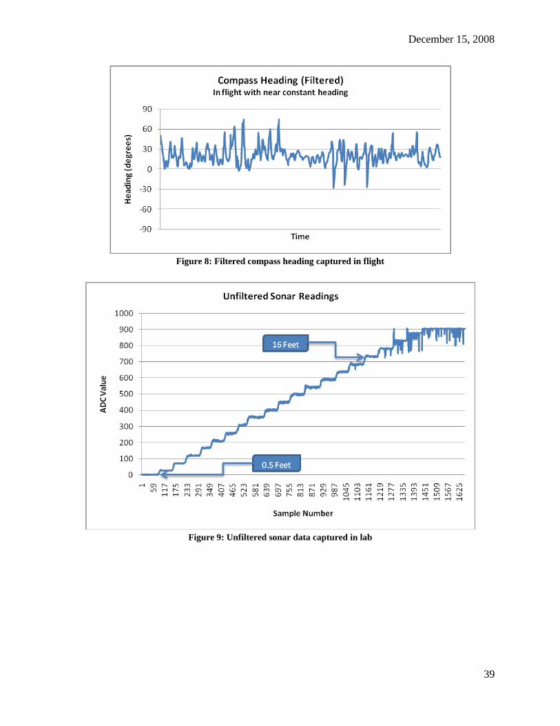
December 15, 2008
39
Figure 8: Filtered compass heading captured in flight
Figure 9: Unfiltered sonar data captured in lab

December 15, 2008
40
Figure 10: Filtered sonar data captured in lab
Figure 11: Class diagrams for ButterworthFilter, IMU_LPFilter, and Compass_LPFilter

December 15, 2008
41
Figure 12: Integration of filter code
Figure 13: Relationship to XML config file

December 15, 2008
42
Figure 14: ButterworthFilter test results
Figure 15: Initial manual override circuit

December 15, 2008
43
Figure 16: Final manual override system
Figure 17: Servo controller behavior
Appendix B: System Requirements
Functional Requirements
FR001: "The aircraft shall be fully autonomous" (Weber et al., 2007, p.19)

December 15, 2008
44
FR002: The aircraft shall not employ tethers for communications with ground station
FR004: The aircraft shall be able to fly 3 km
FR005: The aircraft shall have communications that can span 3 km
FR006: "The aircraft shall be able to fly to within 1 meter of a designated GPS way point"
(Weber et al., 2007, p.19)
FR007: The aircraft shall be equipped with a completely independent termination mechanism
that can render the aircraft ballistic upon command
FR008: "The aircraft shall be able to hover at a GPS point"(Weber et al., 2007, p.19)
FR009: "The aircraft shall be able to take off "(Weber et al., 2007, p.19)
FR010: "The aircraft shall be able to safely land"(Weber et al., 2007, p.19)
FR011: The aircraft shall be able to relay sensor information back to a ground station
FR012: The aircraft shall be able to be controlled manually by an operator in the event that the
aircraft becomes unstable or a hazard to bystanders
FR013: "The aircraft shall be able to be receive GPS way points from a ground station"
(Weber et al., 2007, p.19)
FR014: "The aircraft shall be able to carry a sensor probe to a defined way point"
(Weber et al., 2007, p.19)
FR015: “The aircraft must be able to fly continuously for at least 20 minues” (Weber et al., 2007,
p. 19)
FR016: "The aircraft shall be able to reach an altitude of 50 ft" (Weber et al., 2007, p.19)
FR017: “The aircraft shall be able to sense position and attitude to a height of 50 ft AGL”
(Weber et al, 2007, p. 19)
FR018: “The aircraft shall be able to reach and maintain a horizontal airspeed of 13.03 KTS (15
mph)” (Weber et al., 2007, p. 19)
FR019: “The ground station shall have a GUI with which users can enter information to define a
mission” (Weber et al, 2007, p. 19)
FR020: “The ground station shall be able to display the current state of the aircraft on a GUI”
(Weber et al, 2007, p.19)
Nonfunctional Requirements
NFR01: "The aircraft must weigh less than 14 lbs to not exceed the payload of the motor"
(Weber et al., 2007, p.19)

December 15, 2008
45
Appendix C: Project Schedule & Work Breakdown
Structure
Project Schedule
Spring 2008 Work Breakdown Structure Complete and Test Low/High Pass Filter
2/1/2008 – 4/4/2008
Karl Svec, Matt Beecher, Matt Peyton
Complete and Test Altimeter
2/1/2008 – 4/4/2008
Paul Sanfilippo, Anthony Nowell
Complete and Test Java Ground station
2/1/2008 – 4/4/2008
Andrew Laird, Mike Dent
Test and Calibrate Compass
2/1/2008 – 4/4/2008
Paul Sanfilippo, Alex Brokman
Complete Wire Diagram
2/1/2008 – 4/4/2008
Minh Nguyen, Yan Zhang, Drew Crawford
Complete PreFlight Checklist
2/1/2008 – 4/4/2008
Brad Smith
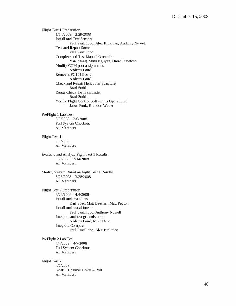
December 15, 2008
46
Flight Test 1 Preparation
1/14/2008 – 2/29/2008
Install and Test Sensors
Paul Sanfilippo, Alex Brokman, Anthony Nowell
Test and Repair Sonar
Paul Sanfilippo
Complete and Test Manual Override
Yan Zhang, Minh Nguyen, Drew Crawford
Modify COM port assignments
Andrew Laird
Remount PC104 Board
Andrew Laird
Check and Repair Helicopter Structure
Brad Smith
Range Check the Transmitter
Brad Smith
Verifiy Flight Control Software is Operational
Jason Funk, Brandon Weber
PreFlight 1 Lab Test
3/3/2008 – 3/6/2008
Full System Checkout
All Members
Flight Test 1
3/7/2008
All Members
Evaluate and Analyze Fight Test 1 Results
3/7/2008 – 3/14/2008
All Members
Modify System Based on Fight Test 1 Results
3/25/2008 – 3/28/2008
All Members
Flight Test 2 Preparation
3/28/2008 – 4/4/2008
Install and test filters
Karl Svec, Matt Beecher, Matt Peyton
Install and test altimeter
Paul Sanfilippo, Anthony Nowell
Integrate and test groundstation
Andrew Laird, Mike Dent
Integrate Compass
Paul Sanfilippo, Alex Brokman
PreFlight 2 Lab Test
4/4/2008 – 4/7/2008
Full System Checkout
All Members
Flight Test 2
4/7/2008
Goal: 1 Channel Hover – Roll
All Members
December 15, 2008
47
Evaluate and Analyze Flight Test 2 Results
4/7/2008 – 4/14/2008
All Members
Modify System based on Flight Test 2 Results
4/14/2008 - 4/21/2008
All Members
Fall 2008 Work Breakdown Structure
Prepare Flight Test 3
9/29/2008 – 10/9/2008
Do Flight Test 3
10/10/2008
Analyze and Evaluate Flight Test 3 Results
10/13/2008 – 10/17/2008
Modify System based on Flight Test 3 Results
10/20/2008 – 10/25/2008
Prepare Flight Test 4
10/27/2008 – 10/30/2008
Do Flight Test 4
10/31/2008
Analyze and Evaluate Flight Test 4 Results
11/3/2008 – 11/7/2008
Modify System based on Flight Test 4 Results
11/10/2008 – 11/14/2008
Prepare Flight Test 5
11/17/2008 – 11/25/2008
Do Flight Test 5
11/26/2008
Analyze and Evaluate Flight Test 5
11/26/2008 – 11/28/2008