Embed Size (px)
Citation preview

Partial discharge monitoring
Easy to install: PLUG & PLAY
Cost-effective solution
Non-intrusive
No need of specific skills
Automatic clustering
Automatic configuration
Automatic Alarms
FALCONPartial Discharge monitoring unit for medium voltage switchgears, cables, transformers and motors
PLUG & PLAY Monitoring
2 FALCON
MEASUREAutomatic detection of partial dischar-ges through sensors located on the cable termination or switchgear enclo-sure
STORAGEHistorical archive of measures up to two years
ANALYSISAutomatic recognition of critical issues as they evolve
ALARMSMaintenance activities only as necessary, and before a failure
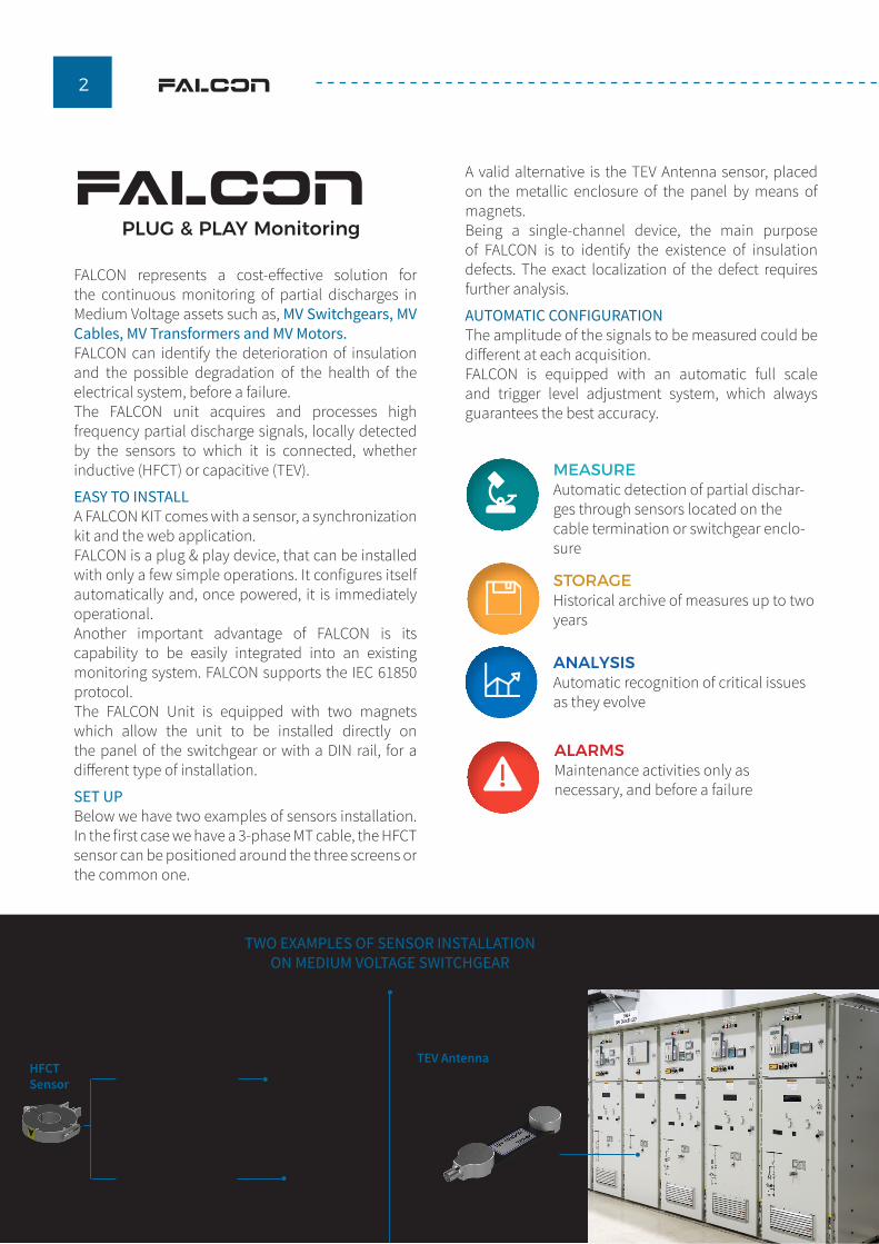
HFCTSensor
TEV Antennaplaced on the metallic enclosure of the panel
TWO EXAMPLES OF SENSOR INSTALLATION ON MEDIUM VOLTAGE SWITCHGEAR
MV cable terminations inside Switchgear connection compartment
MV cable incoming into the switchgear (3-conductor cable)
FALCONPLUG & PLAY Monitoring
FALCON represents a cost-effective solution for the continuous monitoring of partial discharges in Medium Voltage assets such as, MV Switchgears, MV Cables, MV Transformers and MV Motors. FALCON can identify the deterioration of insulation and the possible degradation of the health of the electrical system, before a failure. The FALCON unit acquires and processes high frequency partial discharge signals, locally detected by the sensors to which it is connected, whether inductive (HFCT) or capacitive (TEV).
EASY TO INSTALLA FALCON KIT comes with a sensor, a synchronization kit and the web application. FALCON is a plug & play device, that can be installed with only a few simple operations. It configures itself automatically and, once powered, it is immediately operational.Another important advantage of FALCON is its capability to be easily integrated into an existing monitoring system. FALCON supports the IEC 61850 protocol. The FALCON Unit is equipped with two magnets which allow the unit to be installed directly on the panel of the switchgear or with a DIN rail, for a different type of installation.
SET UPBelow we have two examples of sensors installation. In the first case we have a 3-phase MT cable, the HFCT sensor can be positioned around the three screens or the common one.
A valid alternative is the TEV Antenna sensor, placed on the metallic enclosure of the panel by means of magnets.Being a single-channel device, the main purpose of FALCON is to identify the existence of insulation defects. The exact localization of the defect requires further analysis.
AUTOMATIC CONFIGURATIONThe amplitude of the signals to be measured could be different at each acquisition.FALCON is equipped with an automatic full scale and trigger level adjustment system, which always guarantees the best accuracy.

3FALCON
AUTOMATIC ALARMSThere are different ways to visualize incoming alarms:• From a LED on the unit, that is green if FALCON
doesn’t detect any activity, and red if a harmful activity is detected
• From DRY CONTACTS that could be connected to any local SCADA System
• From FALCON’s WEB APPLICATION, easily available through any web browser, laptop, or smartphone, that shows:- the state of the asset with traffic light logic- the list of alarms due to partial discharge activity- the list of system notifications (communication issues and malfunctions)- the display of trends and important statistical parameters (Qmax, repetition rate, alarms ...)
• From IEC 61850 or OPC UABased on the defect evolution, the FALCON offers an algorithm able to determine if an asset has critical levels of PD. In case the identified PD represents a danger, FALCON sends an alarm to the operator to inform that a critical issue is found.
The alarms are given with 5 levels of severity: GOOD: situation of stability.MODERATE: birth of a phenomenon showing a very slow evolution. In this case it is advisable to schedule a further diagnostic intervention a few months later.SLIGHTLY DETERIORATED: the phenomenon identified is growing.DETERIORATED: it is advisable to schedule a further diagnostic intervention.CRITICAL: the intervention must be scheduled as soon as possible. All the information acquired is stored in FALCON memory and it is available via web application, PC, or smartphone.When an evolving defect occurs, the web application immediately reports the condition of the asset and the criticality level of the defect. The interface is easy to read and doesn’t require any specific skills. It is therefore not necessary to be a partial discharge expert to use the FALCON system.
NETWORK INTEGRATIONThe need to monitor many assets brings with it the need to manage a multitude of data. In the case of integrating the FALCON monitoring system with an existing infrastructure, the communication can take place via various protocols, such as IEC 61850, or the OPC UA, which allows the concentration of information from multiple units in one window. If requested, ALTANOVA can provide TiSCADA software, which provides access to the information of each FALCON connected to the infrastructure that is being managed.
WEB APPLICATIONThe WEB APPLICATION shows:• Status of the monitoring system• Alarm list relevant to partial discharge activity• List of system notifications (communication issues and malfunctions)• Visualization of trending of the most important statistical parameters (Qmax, Repetition rate, Alarms, ...)
WEB APPLICATION
MV CABLE with defect

DS F
ALCO
N E
N -
REV.
02/
2021
The product and the information contained herein may be changed at any time without prior notification. This document nor any parts thereof may not be reproduced or transmitted in any form either electronically or mechanically, including photocopying and recording, without the express written consent of Techimp - ALTANOVA Group Srl, ISA - ALTANOVA Group Srl and IntelliSAW LLC.
www.altanova-group.com
TECHIMP - ALTANOVA GROUP
Via Toscana 11, 40069 Zola Predosa (Bo) - ITALY
Phone +39 051 199 86 050 Email [email protected]
ISA - ALTANOVA GROUP
Via Prati Bassi 22, 21020 Taino (Va) - ITALY
Phone +39 0331 95 60 81 Email [email protected]
IntelliSAW - ALTANOVA GROUP100 Burtt Rd
Andover, MA 01810 (USA)Phone +1 978-409-1534
Email [email protected]
TECHNICAL SPECIFICATION
Partial Discharge
PD channel quantity 1
Bandwidth 16 kHz, 30 MHz
Sampling frequency at full bandwidth 125 MS/s
Resolution 12 bit
Sensitivity 1,10000 mVpeak
Full Scale 5 V peak
Imput impedance 50 Ω
Pre-trigger 0,100% @ 100 μs
Connector type BNC
Synchronization input
Channel quantity 1
Frequency range 5-500Hz
Imput impedance 10 MΩ
Sampling frequency at full bandwidth 1MS/s
Resolution 12 bit
Connector type BNC
Communication system Ethernet connector type10/100/1000 Mb/s
2 LAN ports
Communication protocol
OPCUA - IEC 62541
IEC 61850
Modbus
DNP3
Power supply 12 / 24 VDC , 1A
Working temperature -20°C ÷ +55°C
APPLIED STANDARDStandard Description
93/68/EEC CE Marking Directive
2014/30/EC IEC 61326 (EMC) Electro Magnetic Compatibility
2014/35/EC IEC 61010 (LVD) Low Voltage Directive
IEC 60068-2-6 Environmental testing - Test Fc: Vibration (sinusoidal)
IEC 60270IEC 60034-27IEEE 1434-2014
High-voltage test techniques - Partial discharge measurementsDeviation: Magnitude of the apparent charge is measured in mV