Embed Size (px)
Citation preview
Falcon 3 145, 170, 195 and Tandem Falcon 4 145, 170, 195
Owner / Service ManualJune 2015


500 West Blueridge Ave • Orange, CA • 92865 • Phone (714) 998-6359 • FAX (714) 998-0647http://www.willswing.com • E-mail: [email protected]
June 2015 - First Edition
Copyright © 1994 through 2015 by Sport Kites, Inc. dba Wills Wing, Inc. All rights reserved. No part of this manual may be reproduced in any form without the express written permission of
Sport Kites, Inc., dba Wills Wing, Inc.
Falcon 3 145, 170, 195 and Tandem Falcon 4 145, 170, 195


Contents
Introduction ......................................................................................................1
Disclaimer And Warning ...................................................................................2
Technical Information And Placarded Operating Limitations .................................3
A Note About Platform Towing .........................................................................6
A Few Notes About The Falcon 3 Tandem .........................................................6
A Note About High Duty Cycle Operations .........................................................7
A Note About Parts Replacement and Parts Interchangeability .............................7
Glider Owner’s Manual Addendum – Falcon 3/4, Sport 2 and U2 ........................8
Falcon Breakdown Procedure For Shipping And Reassembly Procedure ................9
Falcon Set-Up Procedure .................................................................................11
Launching And Flying The Falcon.....................................................................23
Using Wing Tufts ............................................................................................23
Trimming Your Glider In Pitch ..........................................................................26
Speeds To Fly And Using Your Airspeed Indicator .............................................28
Landing The Falcon .........................................................................................29
Falcon Breakdown ..........................................................................................33
Falcon Stability Systems .................................................................................34
Maintenance Schedule ....................................................................................36
Removing The Sail From The Airframe And Short Packing The Glider ................37
Falcon Shortpack Bag/Box ...............................................................................38
Installing The Optional Litestream Control Bar Kit ..............................................49
Tuning ...........................................................................................................51
Car Top Mounting And Transport ....................................................................53
In Closing .......................................................................................................53
HGMA Compliance Verification ................................................................54 - 60
Frame Plans .............................................................................................61 - 78
Assembly Diagrams .................................................................................80 - 89


— 1 —
IntroductionThank you for purchasing a Wills Wing glider, and welcome to the world wide family of Wills Wing pilots. We are a company of pilots and aviation enthusiasts, and our goal is to serve your flying needs now and in the future, as we have done for pilots throughout the world since 1973.
We encourage you to read this manual thoroughly for information on the proper use and maintenance of your Wills Wing glider. If at any time you have questions about your glider, or about any aspect of hang gliding that your Wills Wing dealer cannot answer, please feel free to give us a call.
Please visit our web site at http://www.willswing.com on a regular basis. The site features extensive information about Wills Wing gliders and products, a Wills Wing Dealer directory, a comprehensive list of service and technical bulletins, current editions of owners manuals, our complete retail price list, a search engine, and more. Our web site is the means by which we will communicate with you when we have service advisories or other information related to your safety that we need to make you aware of.
We wish you a safe and enjoyable flying career, and, once again, welcome aboard!
Mike Meier, Linda Meier, and Steve Pearson
Wills Wing, Inc.

— 2 —
Disclaimer And WarningHang gliding is a form of aviation. Like any form of aviation, its safe practice demands the consistent exercise of pilot skill, knowledge of airmanship and weather, judgment and attention at a level which is appropriate to the demands of each individual situation. Pilots who do not possess or exercise the required knowledge, skills and judgment are frequently injured and killed. The statistical rate at which fatalities occur in hang gliding is approximately one per thousand participants per year.
The Federal Aviation Administration does not require a pilot’s license to operate a hang glider. Hang gliders and hang gliding equipment are not designed, manufactured, tested or certified to any state or federal government airworthiness standards or requirements. Hang Gliders are not required to be registered with the Federal government. As a result, we do not have a reliable way to keep track of contact information for the owners of Wills Wing hang gliders. It is your responsibility to check with us periodically for safety and airworthiness advisories and information related to your glider. The easiest way to do this is to check our web site at http://www.willswing.com Wills Wing hang gliding products are not covered by product liability insurance. You should never attempt to fly a hang glider without having received competent instruction. We recommend that you not participate in hang glid-ing unless you recognize and wish to personally assume the associated risks.
Please fly safely.
Wills Wing, Inc.
— 3 —
Technical Information And Placarded Operating LimitationsThis manual covers the Falcon 3 145, 170, 195, Falcon 3 Tandem and the the Falcon 4 145, 170, 195.
These gliders have been tested and found to comply with the 2008 HGMA Airworthiness Standards. HGMA Certificates of Compliance were issued for each of these gliders on April 20th, 2009. The Falcon 4 145, 170 and 195 have been tested and found to comply with the 2014 HGMA Standards. At the time of this writing – June 1st, 2015, no certificates of compliance have been issued for these models. Please see www.HGMA.net for updated information on the HGMA certification status of any hang glider
The HGMA Certification standards require:
1. A positive load test at root stall angle of attack at a speed equal to at least the greatest of:
a. 141% of the placarded maximum maneuvering speed
b. 141% of the placarded maximum rough air speed
c. 123% of the placarded speed never to exceed
for at least three seconds without failure.
The required speed for this test was 59 m.p.h..
2. A negative 30 degree angle of attack load test at a speed equal to at least the greatest of:
a. 100% of the placarded maximum maneuvering speed
b. 100% of the placarded maximum rough air speed
c. 87% of the placarded speed never to exceed
for at least 3 seconds without failure.
The required speed for this test was 42 m.p.h..
3. A negative 150 degree angle of attack load test at a speed equal to at least the greater of 30 mph or 50% of the required positive load test speed for at least 3 seconds without failure.
The required speed for this test was 30 m.p.h..
4. Pitch tests at speeds of 20 m.p.h., 34 m.p.h. and 48 m.p.h. which show the glider to have a posi-tive pitching moment coefficient over a range of angles of attack from trim angle to 20 degrees below zero lift angle at 20 m.p.h., and from trim angle to 10 degrees below zero lift angle at 34 m.p.h., and from 10 degrees above zero lift angle to zero lift angle at 48 m.p.h.
5. Flight maneuvers which show the glider to be adequately stable and controllable throughout the normal range of operation.
The Falcon 3's and Falcon 4's have been designed for foot launched soaring flight. They have not been designed to be motorized, tethered, or towed. They can be towed successfully using proper towing procedures. Pilots wishing to tow should be USHGA skill rated for towing, and should avail themselves of all available information on the most current proper and safe towing procedures. Sug-gested sources for towing information include the United States Hang Gliding Association and the manufacturer of the towing winch / or equipment being used. Wills Wing makes no warranty of the suit-ability of the glider for towing.
— 4 —
Flight operation of the Falcon should be limited to non aerobatic maneuvers; those in which the pitch angle will not exceed 30 degrees nose up or nose down from the horizon, and the bank angle will not exceed 60 degrees. The Falcon is generally resistant to spinning, but will spin from a stalled turn at bank angles of 40 degrees or more, or if the pilot applies positive pitch control aggressively in com-bination with roll control input so as to roll towards the high wing. Recovery from a spin requires un-stalling of the wing, and it is therefore important that in the event of a spin, no application of nose up pitch control be held. The Falcon will recover from a spin once control pressures are relaxed. As the nose lowers and the angle of attack is reduced, the stall will be broken and the spin will stop. How-ever, such recovery will consume significant altitude, and will result in the glider assuming an unpre-dictable heading. Recovery from a spin may therefore involve a flight trajectory which intersects the terrain at a high rate of speed. An aggravated spin could result in loss of control, in flight inversion, and structural failure. Therefore no attempt should ever be made to deliberately spin the glider.
The maximum steady state speed for a prone pilot in the middle of the recommended weight range full forward on the control bar is approximately 42 m.p.h. for the Falcon. The placarded speed never to exceed and maximum maneuvering speeds for the Falcons are:
Model Vne Va Falcon 3/4 145, 170, 195 48 mph 42 mph Falcon 3 Tandem 48 mph 42 mph
The Falcon can be flown in steady state high speed flight with the pilot full forward over the bar with-out exceeding the VNE speed. Abrupt maneuvers may cause the glider to exceed VNE, and abrupt maneuvers should not be made from speeds above 42 mph.
The stability, controllability, and structural strength of a properly maintained Falcon have been de-termined to be adequate for safe operation when the glider is operated within all of the manufacturer specified limitations. No warranty of adequate stability, controllability, or structural strength is made or implied for operation outside of these limitations.
The stall speed of the Falcon at maximum recommended wing loading is 25 mph or less. The top (steady state) speed at minimum recommended wing loading for a prone pilot with a properly de-signed and adjusted harness is at least 35 mph.
All speeds given above are indicated airspeeds, for a properly calibrated airspeed indicator mounted in the vicinity of the pilot. Such an airspeed indicator is available through your Wills Wing dealer.
The recommended hook in pilot weight range for the Falcon 3 and Falcon 4 is:
Falcon 3/4 145: 120 - 190 lbs. Falcon 3/4 170: 140 - 220 lbs. Falcon 3/4 195: 175 - 275 lbs. Falcon 3 Tandem: 185 - 500 lbs.
Be advised that pilots with hook in weights within 20 lbs of the minimum recommended will find the Falcon somewhat more demanding of pilot skill to fly, and that pilots with hook in weights of more than 130% of the minimum recommended will experience some relative degradation of optimum sink rate performance due to their higher wing loading. Please note that the term "recommended hook in pilot weight range" comes from the HGMA certification standards, and without some qualification, may be misleading. The recommended weight ranges as listed above represent the full range of pilot hook in weights over which the model listed will retain adequate stability, performance, control, and
— 5 —
structural strength. A more appropriate term for the weight ranges listed above might be the "allow-able" pilot hook in weight range. The pilot hook in weight ranges which we would actually "recom-mend" as being optimum are given in the following table:
The optimum hook in pilot weight range for the Falcon 3 is:
Falcon 3/4 145: 140 - 165 lbs. Falcon 3/4 170: 165 - 200 lbs. Falcon 3/4 195: 200 - 240 lbs. Falcon 3 Tandem: 240 - 450 lbs.
The Falcon 3 and 4 models have superior aerodynamic performance to that of the corresponding Falcon 1 models, especially at the lower end of the speed range. On average, a given size Falcon 3 or Falcon 4 will have a 2 mph lower stall speed, with the same pilot weight, as the corresponding Falcon 1. This allows a heavier pilot to achieve the same, or better sink rate on the same size of the Falcon 3/4.
A minimum USHGA Novice (II) level of pilot proficiency is required to fly the Falcon safely, unless under the direct supervision of a qualified instructor.
Operation of the glider by unqualified or under qualified pilots may be dangerous.
Operating the Falcon outside of the above limitations may result in injury and death. Flying the Falcon in the presence of strong or gusty winds, or turbulence may result in loss of control of the glider which may lead to injury and death. Do not fly in such conditions unless you realize and wish to personally assume the associated risks. Wills Wing is well aware that pilots have, and continue to perform maneuvers and fly in conditions which are outside the recommended operating limitations stated herein. Please be aware that the fact that some pilots have exceeded these limitations in the past without dangerous incident does not imply or insure that the limitations may be exceeded without risk. We do know that gliders which meet all current industry standards for airworthiness can and do suffer in flight structural failures, both as a result of turbulence, and as a result of various maneuvers outside the placarded operating limitations, including, but not necessarily limited to aerobatics. We do not know, and cannot know, the full range of maneuvers or conditions which may cause the pilot’s safety to be compromised, nor can we test the glider in all possible circumstances.
— 6 —
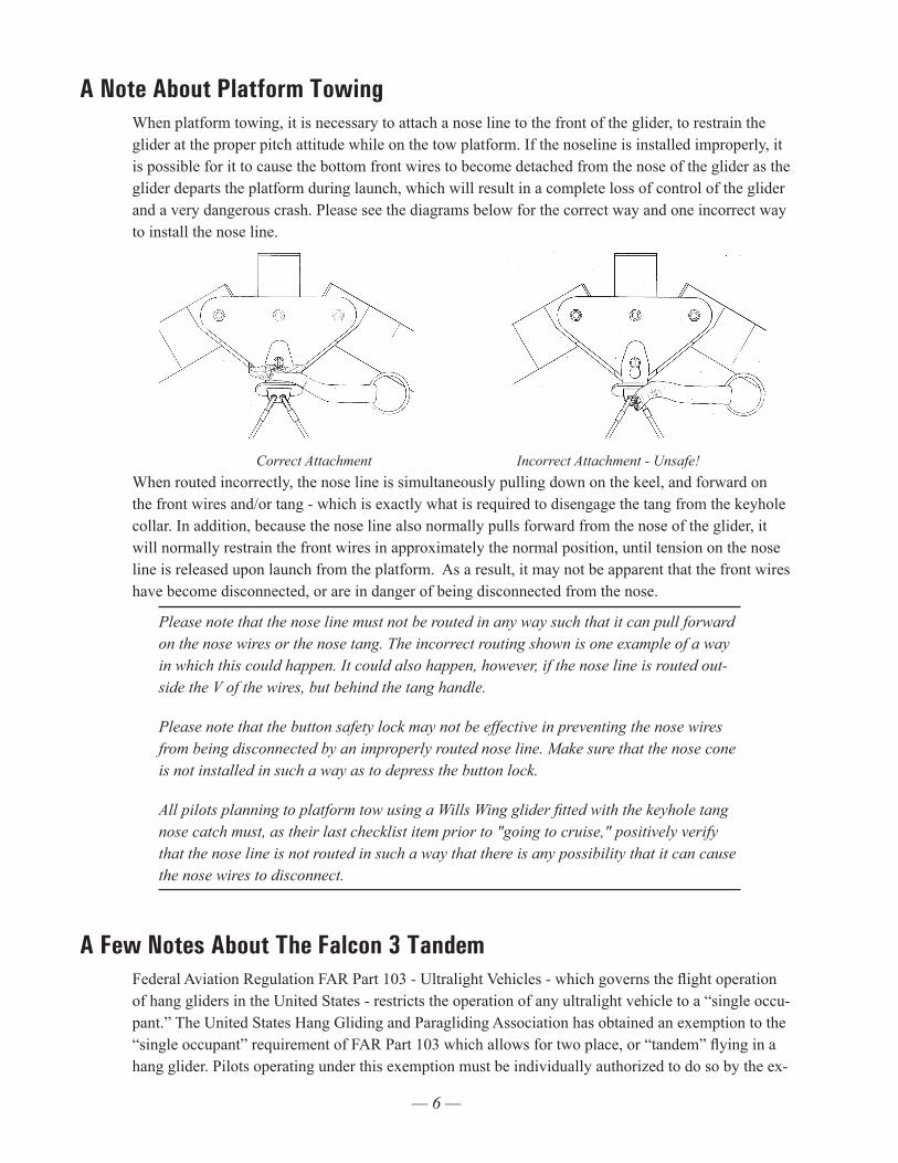
A Note About Platform TowingWhen platform towing, it is necessary to attach a nose line to the front of the glider, to restrain the glider at the proper pitch attitude while on the tow platform. If the noseline is installed improperly, it is possible for it to cause the bottom front wires to become detached from the nose of the glider as the glider departs the platform during launch, which will result in a complete loss of control of the glider and a very dangerous crash. Please see the diagrams below for the correct way and one incorrect way to install the nose line.
Correct Attachment Incorrect Attachment - Unsafe!
When routed incorrectly, the nose line is simultaneously pulling down on the keel, and forward on the front wires and/or tang - which is exactly what is required to disengage the tang from the keyhole collar. In addition, because the nose line also normally pulls forward from the nose of the glider, it will normally restrain the front wires in approximately the normal position, until tension on the nose line is released upon launch from the platform. As a result, it may not be apparent that the front wires have become disconnected, or are in danger of being disconnected from the nose.
Please note that the nose line must not be routed in any way such that it can pull forward on the nose wires or the nose tang. The incorrect routing shown is one example of a way in which this could happen. It could also happen, however, if the nose line is routed out-side the V of the wires, but behind the tang handle.
Please note that the button safety lock may not be effective in preventing the nose wires from being disconnected by an improperly routed nose line. Make sure that the nose cone is not installed in such a way as to depress the button lock.
All pilots planning to platform tow using a Wills Wing glider fitted with the keyhole tang nose catch must, as their last checklist item prior to "going to cruise," positively verify that the nose line is not routed in such a way that there is any possibility that it can cause the nose wires to disconnect.
A Few Notes About The Falcon 3 TandemFederal Aviation Regulation FAR Part 103 - Ultralight Vehicles - which governs the flight operation of hang gliders in the United States - restricts the operation of any ultralight vehicle to a “single occu-pant.” The United States Hang Gliding and Paragliding Association has obtained an exemption to the “single occupant” requirement of FAR Part 103 which allows for two place, or “tandem” flying in a hang glider. Pilots operating under this exemption must be individually authorized to do so by the ex-
— 7 —
emption holder, and must operate under all of the requirements of the exemption in order to conduct legal two place flight operations. It is the pilot’s responsibility to have the necessary skills, knowledge and experience, to obtain the proper authorization to operate under the exemption, and to operate un-der the requirements of the exemption. Tandem or two place hang glider flight requires special skills, experience and knowledge that are far beyond what is required for single place operations. Based on flight testing and other testing conducted by Wills Wing on the Falcon 3 Tandem glider, we believe that the Falcon 3 Tandem is suitable for two place flight, provided that the pilot in command has all the necessary knowledge, skills and experience to conduct such flight operations safely, and follows all appropriate procedures for safe two place flight. The Falcon 3 Tandem model can also be flown single place by a pilot within the recommended weight range, and in the case of single place opera-tion, a minimum USHGA Novice (II) level of pilot proficiency is required to fly the Falcon 3 Tandem safely, unless under the direct supervision of a qualified instructor.
This information covers only the Falcon 3 Tandem - see the appropriate Owner/Service Manuals for important information about previous Falcon Tandem and Falcon 225 models.
A Note About High Duty Cycle OperationsGliders which are used in a training environment, or in any situation which involves a high number of flight operations over short period of time, will require an accelerated maintenance program in order to maintain adequate airworthiness. The design and testing of these gliders does not necessarily take into account the types of wear which may result from high duty cycle operations. The operator must take responsibility to thoroughly and adequately inspect the glider to determine whether maintenance is being conducted on a schedule appropriate to maintain the airworthiness of the glider.
A Note About Parts Replacement and Parts InterchangeabilityFalcon 1's, Falcon 2's, Falcon 3's and Falcon 4's share a number of parts, but many parts are different. In addition, there are configuration variations within a given model line. When ordering replacement parts, it is very important to provide the glider serial number to insure that the correct replacement parts are provided. The serial number is a five digit number, beginning with the number 2, and can normally be found in three places on the glider - written inside the nose of the sail (most reliable), on an adhesive label on the bottom of the keel at the nose, and written on the operating limitations plac-ard on the bottom of the rear of the keel. Please also note that some configuration options - such as basetube type, (straight vs. speedbar, or .095 wall vs. .065 wall), or optional Litestream Control Bar, may have changed since the glider was produced, so it is necessary to specify this information when ordering these parts.
— 8 —
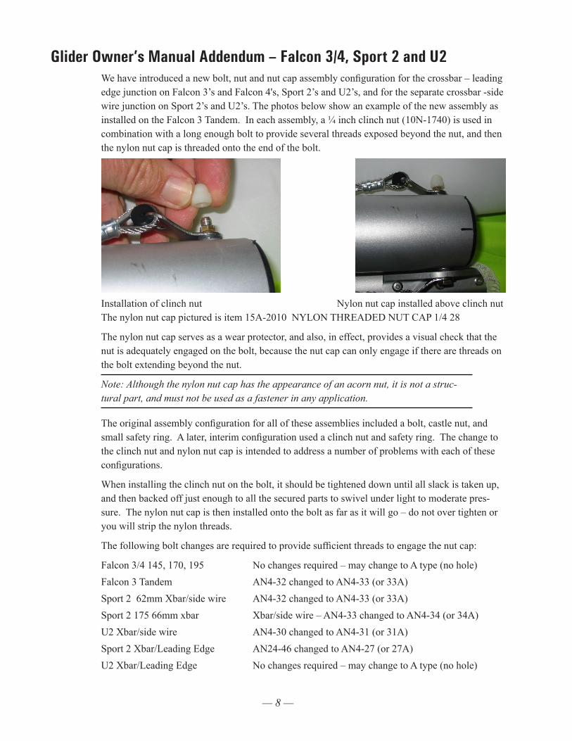
Glider Owner’s Manual Addendum – Falcon 3/4, Sport 2 and U2We have introduced a new bolt, nut and nut cap assembly configuration for the crossbar – leading edge junction on Falcon 3’s and Falcon 4's, Sport 2’s and U2’s, and for the separate crossbar -side wire junction on Sport 2’s and U2’s. The photos below show an example of the new assembly as installed on the Falcon 3 Tandem. In each assembly, a ¼ inch clinch nut (10N-1740) is used in combination with a long enough bolt to provide several threads exposed beyond the nut, and then the nylon nut cap is threaded onto the end of the bolt.
Installation of clinch nut Nylon nut cap installed above clinch nut The nylon nut cap pictured is item 15A-2010 NYLON THREADED NUT CAP 1/4 28
The nylon nut cap serves as a wear protector, and also, in effect, provides a visual check that the nut is adequately engaged on the bolt, because the nut cap can only engage if there are threads on the bolt extending beyond the nut.
Note: Although the nylon nut cap has the appearance of an acorn nut, it is not a struc-tural part, and must not be used as a fastener in any application.
The original assembly configuration for all of these assemblies included a bolt, castle nut, and small safety ring. A later, interim configuration used a clinch nut and safety ring. The change to the clinch nut and nylon nut cap is intended to address a number of problems with each of these configurations.
When installing the clinch nut on the bolt, it should be tightened down until all slack is taken up, and then backed off just enough to all the secured parts to swivel under light to moderate pres-sure. The nylon nut cap is then installed onto the bolt as far as it will go – do not over tighten or you will strip the nylon threads.
The following bolt changes are required to provide sufficient threads to engage the nut cap:
Falcon 3/4 145, 170, 195 No changes required – may change to A type (no hole)Falcon 3 Tandem AN4-32 changed to AN4-33 (or 33A)Sport 2 62mm Xbar/side wire AN4-32 changed to AN4-33 (or 33A)Sport 2 175 66mm xbar Xbar/side wire – AN4-33 changed to AN4-34 (or 34A)U2 Xbar/side wire AN4-30 changed to AN4-31 (or 31A)Sport 2 Xbar/Leading Edge AN24-46 changed to AN4-27 (or 27A)U2 Xbar/Leading Edge No changes required – may change to A type (no hole)
— 9 —
Falcon Breakdown Procedure For Shipping And Reassembly ProcedureThe Falcon 3 and Falcon 4 can be broken down to approximately 2/3 of its normal length by removal of the rear leading edges. Alternately, the Falcon 3 145, 170, 195 and the Falcon 4 145, 170 and 195 when equipped with the optional breakdown configuration can be short-packed to less than a seven foot length, by removing the sail and further disassembling the airframe. This section of the manual covers the 2/3 length breakdown and reassembly procedure. Note that the procedure for the Falcon 3 Tandem is slightly different, due to differences in the leading edge construction. The different proce-dures for the Falcon 3 Tandem are specified in each section of the instructions.
To break down the leading edges follow these steps1. Lay the glider on the ground or floor, unzip and remove the bag and remove the velcro ties. Undo
the velcros that hold the sail around the aft end of the rear leading edge at the rear sail mount and pull the sail rearward at each tip to dismount the sail from the rear leading edge. You may use a large, flat bladed screw driver to pry the sail mount webbing away from the slotted endcap. Take care that the screwdriver does not have a sharp edge which might cut or damage the webbing.
2. Obtain an indelible marker. Check to see if the rear leading edges are labeled left and right. If they are not, mark the rear leading edges left and right (remember that left and right are reversed if the glider is lying “on its back”, upside down.
3. On the Falcon 3 and Falcon 4 145, 170, or 195, the junction of the rear leading edge and front leading edge is aft of the leading edge / crossbar junction. The forward edge of the rear leading edge is slotted, and this slot engages on a clevis pin in the rear portion of the oversleeve on the front leading edge. Pull the rear leading edge straight aft to disengage it from the front. On the Falcon 3 Tandem, the junction of the rear and front leading edges is forward of the leading edge / crossbar junction (the reinforcing sleeve is internal instead of external, and is attached to the rear leading edge instead of the front.) “To disengage the rear leading edge, first disassemble the lead-ing edge / crossbar attachment by removing the safety ring, nut, and bolt. Reinstall the bolt, nut and safety ring, with the wires attached, in the crossbar end. (Note: You will want to replace this safety ring with a new one when you reassemble this junction if the safety ring has been in any way distorted by the removal and reinstallation process.) Next remove the clevis pin and safety ring located just forward of the visible splice in the leading edge (eight inches forward of the leading edge / crossbar junction), and pull the rear leading edge aft to disengage it from the front. Reinstall the clevis pin and safety. In all cases, cover the sharp edges of both the front and rear leading edge tubes with padding to protect the tubes and the sail from damage during transport.
4. Lay the mylar pockets flat so as to avoid creasing the mylar when you fold over the rear portion of the sail. Replace the sail ties loosely, zip up the bag, and carefully fold the rear of the glider over against the front.
Remounting the rear leading edges 1. Set the glider on its back (upside down). Unfold the glider, open the bag and lay the sail out full
length. Make sure you are mounting the correct leading edge rear into the correct front (check the “right” / “left” designation, and remember that left / right are reversed when the glider is lying upside down, on its back).
2. Wipe the forward six inches of the rear leading edge with a clean cloth to remove any dirt or grit.
— 10 —
3. Slide the rear leading edge tube into the sail, and then into the front leading edge, as far as it will go until you encounter a hard stop. This will be the forward edge of the rear leading edge con-tacting the clevis pin in the front leading edge
4. On the Falcon 3 Falcon 4 145, 1770 and 195, rotate the rear leading edge so that the washout tube receptacle faces inwards, towards the opposite leading edge, and then continue to rotate the leading edge slowly so as to rotate the washout tube receptacle towards the ground (“upwards” relative to the glider), while maintaining forward pressure on the rear leading edge, until you feel the rear leading edge slide forward as the slot in the rear leading edge engages on the clevis pin. Verify that the rear leading edge is as far forward as it will go, and that it is locked against rota-tion by the engagement of the slot on the clevis pin.
On the Falcon 3 Tandem, remove the clevis pin and safety in the front leading edge, and slide the rear leading edge all the way forward. Rotate the rear leading edge so that the washout tube receptacle faces inwards, towards the opposite leading edge, and then continue to rotate the lead-ing edge so as to rotate the washout tube receptacle towards the ground until the clevis pin holes line up. Re-install the clevis pin and safety, taking note that the safety is installed on the top of the leading edge (which will be on the bottom, at this point, because the glider is upside down).
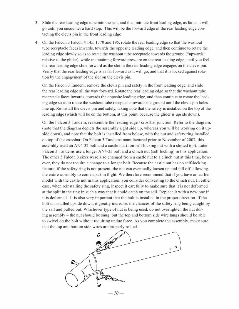
On the Falcon 3 Tandem, reassemble the leading edge / crossbar junction. Refer to the diagram, (note that the diagram depicts the assembly right side up, whereas you will be working on it up-side down), and note that the bolt is installed from below, with the nut and safety ring installed on top of the crossbar. On Falcon 3 Tandems manufactured prior to November of 2007, this assembly used an AN4-32 bolt and a castle nut (non-self locking nut with a slotted top). Later Falcon 3 Tandems use a longer AN4-33 bolt and a clinch nut (self locking) in this application. The other 3 Falcon 3 sizes were also changed from a castle nut to a clinch nut at this time, how-ever, they do not require a change to a longer bolt. Because the castle nut has no self-locking feature, if the safety ring is not present, the nut can eventually loosen up and fall off, allowing the entire assembly to come apart in flight. We therefore recommend that if you have an earlier model with the castle nut in this application, you consider converting to the clinch nut. In either case, when reinstalling the safety ring, inspect it carefully to make sure that it is not deformed at the split in the ring in such a way that it could catch on the sail. Replace it with a new one if it is deformed. It is also very important that the bolt is installed in the proper direction. If the bolt is installed upside down, it greatly increases the chances of the safety ring being caught by the sail and pulled out. Whichever type of nut is being used, do not overtighten the nut dur-ing assembly – the nut should be snug, but the top and bottom side wire tangs should be able to swivel on the bolt without requiring undue force. As you complete the assembly, make sure that the top and bottom side wires are properly routed.
— 11 —
5. Remount the sail to the rear leading edge, making sure to align the inner sail mount webbing (NOT the outer webbing handle!) squarely in the slot and attach the securing velcros. Make sure the sail is properly oriented—the velcros should be on the inside of the leading edges.
You may find it helpful to use a large, flat bladed screw driver to pry the sail mount webbing over the end of the leading edge tube and into the slot. Take care not to damage the webbing. Alternately, first remove the sail mount screws located at the front of each leading edge to release the tension. The sail mount screws may be difficult to replace until after the glider is completely assembled. Spread the wings carefully and incrementally while pulling the sail forward at the nose during assembly to prevent damage to the sail.
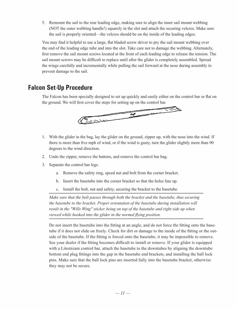
Falcon Set-Up ProcedureThe Falcon has been specially designed to set up quickly and easily either on the control bar or flat on the ground. We will first cover the steps for setting up on the control bar.
1. With the glider in the bag, lay the glider on the ground, zipper up, with the nose into the wind. If there is more than five mph of wind, or if the wind is gusty, turn the glider slightly more than 90 degrees to the wind direction.
2. Undo the zipper, remove the battens, and remove the control bar bag.
3. Separate the control bar legs.
a. Remove the safety ring, speed nut and bolt from the corner bracket.
b. Insert the basetube into the corner bracket so that the holes line up.
c. Install the bolt, nut and safety, securing the bracket to the basetube.
Make sure that the bolt passes through both the bracket and the basetube, thus securing the basetube to the bracket. Proper orientation of the basetube during installation will result in the "Wills Wing" sticker being on top of the basetube and right side up when viewed while hooked into the glider in the normal flying position.
Do not insert the basetube into the fitting at an angle, and do not force the fitting onto the base-tube if it does not slide on freely. Check for dirt or damage to the inside of the fitting or the out-side of the basetube. If the fitting is forced onto the basetube, it may be impossible to remove. See your dealer if the fitting becomes difficult to install or remove. If your glider is equipped with a Litestream control bar, attach the basetube to the downtubes by aligning the downtube bottom end plug fittings into the gap in the basetube end brackets, and installing the ball lock pins. Make sure that the ball lock pins are inserted fully into the basetube bracket, otherwise they may not be secure.
— 12 —
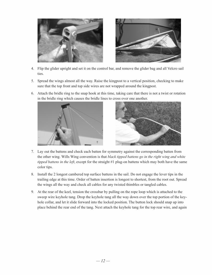
4. Flip the glider upright and set it on the control bar, and remove the glider bag and all Velcro sail ties.
5. Spread the wings almost all the way. Raise the kingpost to a vertical position, checking to make sure that the top front and top side wires are not wrapped around the kingpost.
6. Attach the bridle ring to the snap hook at this time, taking care that there is not a twist or rotation in the bridle ring which causes the bridle lines to cross over one another.
7. Lay out the battens and check each batten for symmetry against the corresponding batten from the other wing. Wills Wing convention is that black tipped battens go in the right wing and white tipped battens in the left, except for the straight #1 plug-on battens which may both have the same color tips.
8. Install the 2 longest cambered top surface battens in the sail. Do not engage the lever tips in the trailing edge at this time. Order of batten insertion is longest to shortest, from the root out. Spread the wings all the way and check all cables for any twisted thimbles or tangled cables.
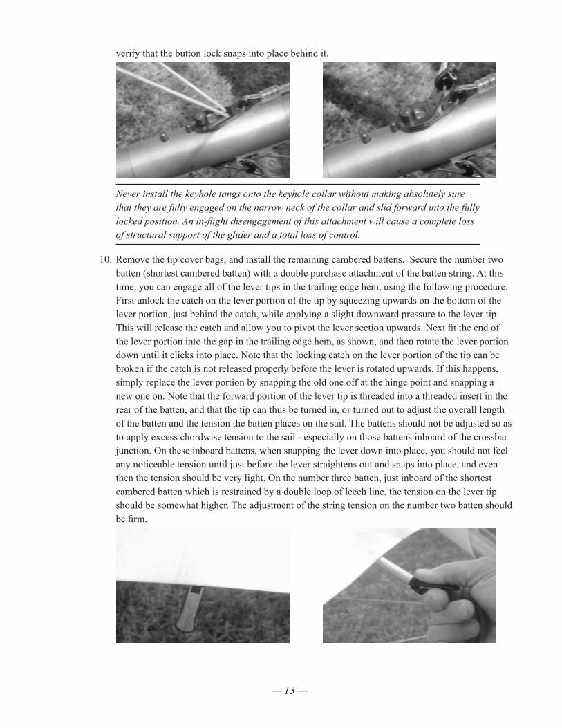
9. At the rear of the keel, tension the crossbar by pulling on the rope loop which is attached to the sweep wire keyhole tang. Drop the keyhole tang all the way down over the top portion of the key-hole collar, and let it slide forward into the locked position. The button lock should snap up into place behind the rear end of the tang. Next attach the keyhole tang for the top rear wire, and again
— 13 —
verify that the button lock snaps into place behind it.
Never install the keyhole tangs onto the keyhole collar without making absolutely sure that they are fully engaged on the narrow neck of the collar and slid forward into the fully locked position. An in-flight disengagement of this attachment will cause a complete loss of structural support of the glider and a total loss of control.
10. Remove the tip cover bags, and install the remaining cambered battens. Secure the number two batten (shortest cambered batten) with a double purchase attachment of the batten string. At this time, you can engage all of the lever tips in the trailing edge hem, using the following procedure. First unlock the catch on the lever portion of the tip by squeezing upwards on the bottom of the lever portion, just behind the catch, while applying a slight downward pressure to the lever tip. This will release the catch and allow you to pivot the lever section upwards. Next fit the end of the lever portion into the gap in the trailing edge hem, as shown, and then rotate the lever portion down until it clicks into place. Note that the locking catch on the lever portion of the tip can be broken if the catch is not released properly before the lever is rotated upwards. If this happens, simply replace the lever portion by snapping the old one off at the hinge point and snapping a new one on. Note that the forward portion of the lever tip is threaded into a threaded insert in the rear of the batten, and that the tip can thus be turned in, or turned out to adjust the overall length of the batten and the tension the batten places on the sail. The battens should not be adjusted so as to apply excess chordwise tension to the sail - especially on those battens inboard of the crossbar junction. On these inboard battens, when snapping the lever down into place, you should not feel any noticeable tension until just before the lever straightens out and snaps into place, and even then the tension should be very light. On the number three batten, just inboard of the shortest cambered batten which is restrained by a double loop of leech line, the tension on the lever tip should be somewhat higher. The adjustment of the string tension on the number two batten should be firm.
— 14 —
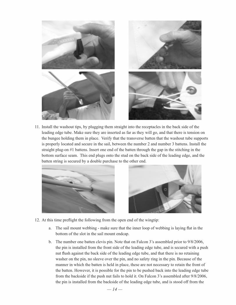
11. Install the washout tips, by plugging them straight into the receptacles in the back side of the leading edge tube. Make sure they are inserted as far as they will go, and that there is tension on the bungee holding them in place. Verify that the transverse batten that the washout tube supports is properly located and secure in the sail, between the number 2 and number 3 battens. Install the straight plug-on #1 battens. Insert one end of the batten through the gap in the stitching in the bottom surface seam. This end plugs onto the stud on the back side of the leading edge, and the batten string is secured by a double purchase to the other end.
12. At this time preflight the following from the open end of the wingtip:
a. The sail mount webbing - make sure that the inner loop of webbing is laying flat in the bottom of the slot in the sail mount endcap.
b. The number one batten clevis pin. Note that on Falcon 3’s assembled prior to 9/8/2006, the pin is installed from the front side of the leading edge tube, and is secured with a push nut flush against the back side of the leading edge tube, and that there is no retaining washer on the pin, no sleeve over the pin, and no safety ring in the pin. Because of the manner in which the batten is held in place, these are not necessary to retain the front of the batten. However, it is possible for the pin to be pushed back into the leading edge tube from the backside if the push nut fails to hold it. On Falcon 3’s assembled after 9/8/2006, the pin is installed from the backside of the leading edge tube, and is stood off from the
— 15 —
tube surface by a short, 1/4 inch diameter sleeve, and secured on the front side of the leading edge tube with a small safety ring covered by protective tape. If you have a prob-lem with the earlier configuration, we recommend that you convert to the later assembly. Note also that the number one batten can become disengaged in flight, if the retaining string is too loose. The string should be adjusted as tight as it can be, without being so tight that it slackens the sail mount webbing or pulls the webbing away from the slot in the endcap.
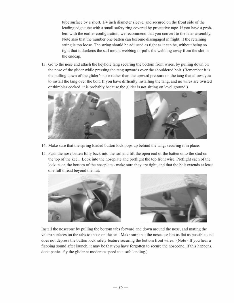
13. Go to the nose and attach the keyhole tang securing the bottom front wires, by pulling down on the nose of the glider while pressing the tang upwards over the shouldered bolt. (Remember it is the pulling down of the glider’s nose rather than the upward pressure on the tang that allows you to install the tang over the bolt. If you have difficulty installing the tang, and no wires are twisted or thimbles cocked, it is probably because the glider is not sitting on level ground.)
14. Make sure that the spring loaded button lock pops up behind the tang, securing it in place.
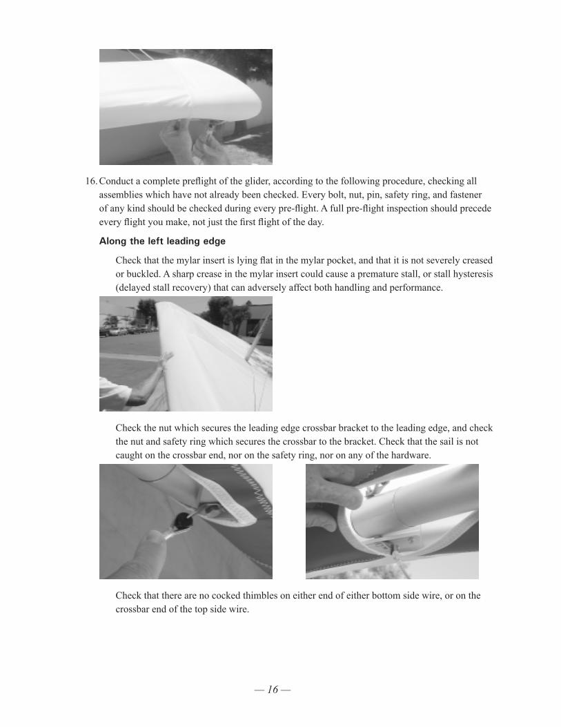
15. Push the nose batten fully back into the sail and lift the open end of the batten onto the stud on the top of the keel. Look into the noseplate and preflight the top front wire. Preflight each of the lockuts on the bottom of the noseplate - make sure they are tight, and that the bolt extends at least one full thread beyond the nut.
Install the nosecone by pulling the bottom tabs forward and down around the nose, and mating the velcro surfaces on the tabs to those on the sail. Make sure that the nosecose lies as flat as possible, and does not depress the button lock safety feature securing the bottom front wires. (Note - If you hear a flapping sound after launch, it may be that you have forgotten to secure the nosecone. If this happens, don't panic - fly the glider at moderate speed to a safe landing.)
— 16 —
16. Conduct a complete preflight of the glider, according to the following procedure, checking all assemblies which have not already been checked. Every bolt, nut, pin, safety ring, and fastener of any kind should be checked during every pre-flight. A full pre-flight inspection should precede every flight you make, not just the first flight of the day.
Along the left leading edge
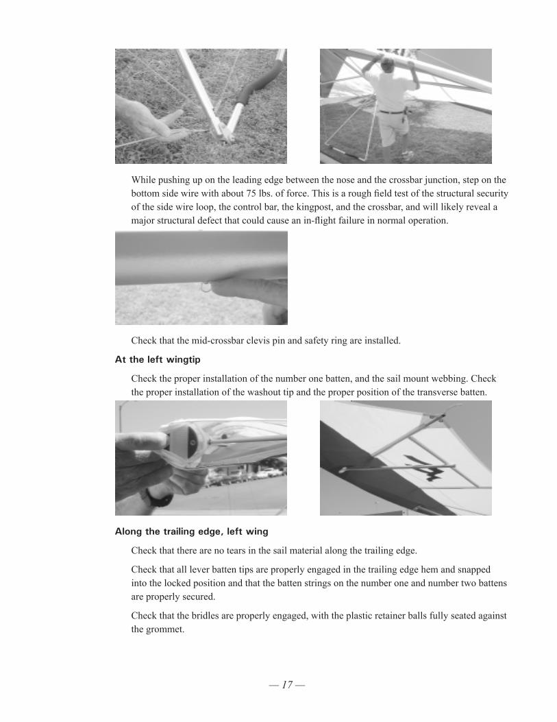
Check that the mylar insert is lying flat in the mylar pocket, and that it is not severely creased or buckled. A sharp crease in the mylar insert could cause a premature stall, or stall hysteresis (delayed stall recovery) that can adversely affect both handling and performance.
Check the nut which secures the leading edge crossbar bracket to the leading edge, and check the nut and safety ring which secures the crossbar to the bracket. Check that the sail is not caught on the crossbar end, nor on the safety ring, nor on any of the hardware.
Check that there are no cocked thimbles on either end of either bottom side wire, or on the crossbar end of the top side wire.
— 17 —
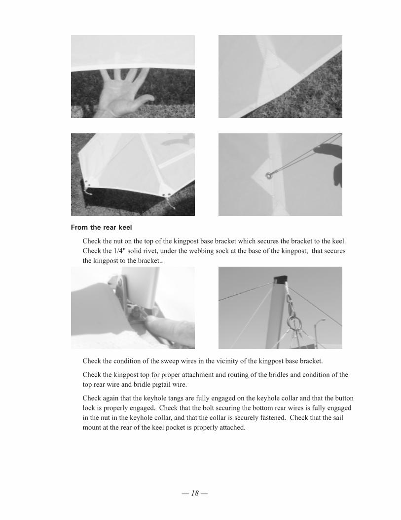
While pushing up on the leading edge between the nose and the crossbar junction, step on the bottom side wire with about 75 lbs. of force. This is a rough field test of the structural security of the side wire loop, the control bar, the kingpost, and the crossbar, and will likely reveal a major structural defect that could cause an in-flight failure in normal operation.
Check that the mid-crossbar clevis pin and safety ring are installed.
At the left wingtip
Check the proper installation of the number one batten, and the sail mount webbing. Check the proper installation of the washout tip and the proper position of the transverse batten.
Along the trailing edge, left wing
Check that there are no tears in the sail material along the trailing edge.
Check that all lever batten tips are properly engaged in the trailing edge hem and snapped into the locked position and that the batten strings on the number one and number two battens are properly secured.
Check that the bridles are properly engaged, with the plastic retainer balls fully seated against the grommet.
— 18 —
From the rear keel
Check the nut on the top of the kingpost base bracket which secures the bracket to the keel. Check the 1/4" solid rivet, under the webbing sock at the base of the kingpost, that secures the kingpost to the bracket..
Check the condition of the sweep wires in the vicinity of the kingpost base bracket.
Check the kingpost top for proper attachment and routing of the bridles and condition of the top rear wire and bridle pigtail wire.
Check again that the keyhole tangs are fully engaged on the keyhole collar and that the button lock is properly engaged. Check that the bolt securing the bottom rear wires is fully engaged in the nut in the keyhole collar, and that the collar is securely fastened. Check that the sail mount at the rear of the keel pocket is properly attached.
— 19 —
Along the trailing edge, right wing
Same as for left wing.
At the right tip
Same as for left tip.
Along the right leading edge
Same as for left leading edge.
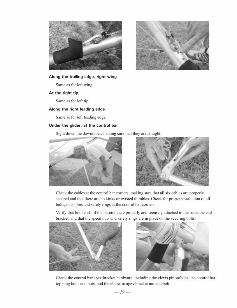
Under the glider, at the control bar
Sight down the downtubes, making sure that they are straight.
Check the cables at the control bar corners, making sure that all six cables are properly secured and that there are no kinks or twisted thimbles. Check for proper installation of all bolts, nuts, pins and safety rings at the control bar corners.
Verify that both ends of the basetube are properly and securely attached to the basetube end bracket, and that the speed nuts and safety rings are in place on the securing bolts.
Check the control bar apex bracket hardware, including the clevis pin safeties, the control bar top plug bolts and nuts, and the elbow to apex bracket nut and bolt.
— 20 —
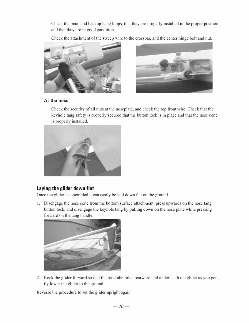
Check the main and backup hang loops, that they are properly installed in the proper position and that they are in good condition.
Check the attachment of the sweep wire to the crossbar, and the center hinge bolt and nut.
At the nose
Check the security of all nuts at the noseplate, and check the top front wire. Check that the keyhole tang safety is properly secured that the button lock is in place and that the nose cone is properly installed.
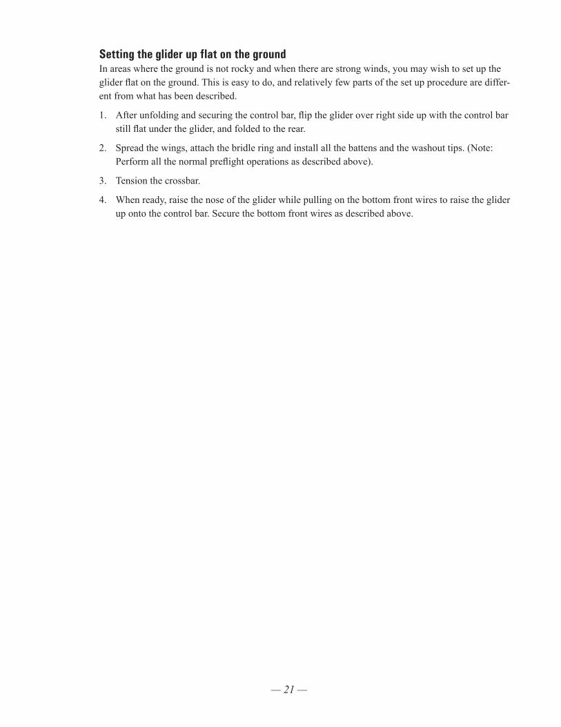
Laying the glider down flatOnce the glider is assembled it can easily be laid down flat on the ground.
1. Disengage the nose cone from the bottom surface attachment, press upwards on the nose tang button lock, and disengage the keyhole tang by pulling down on the nose plate while pressing forward on the tang handle.
2. Rock the glider forward so that the basetube folds rearward and underneath the glider as you gen-tly lower the glider to the ground.
Reverse the procedure to set the glider upright again.
— 21 —
Setting the glider up flat on the groundIn areas where the ground is not rocky and when there are strong winds, you may wish to set up the glider flat on the ground. This is easy to do, and relatively few parts of the set up procedure are differ-ent from what has been described.
1. After unfolding and securing the control bar, flip the glider over right side up with the control bar still flat under the glider, and folded to the rear.
2. Spread the wings, attach the bridle ring and install all the battens and the washout tips. (Note: Perform all the normal preflight operations as described above).
3. Tension the crossbar.
4. When ready, raise the nose of the glider while pulling on the bottom front wires to raise the glider up onto the control bar. Secure the bottom front wires as described above.
— 22 —
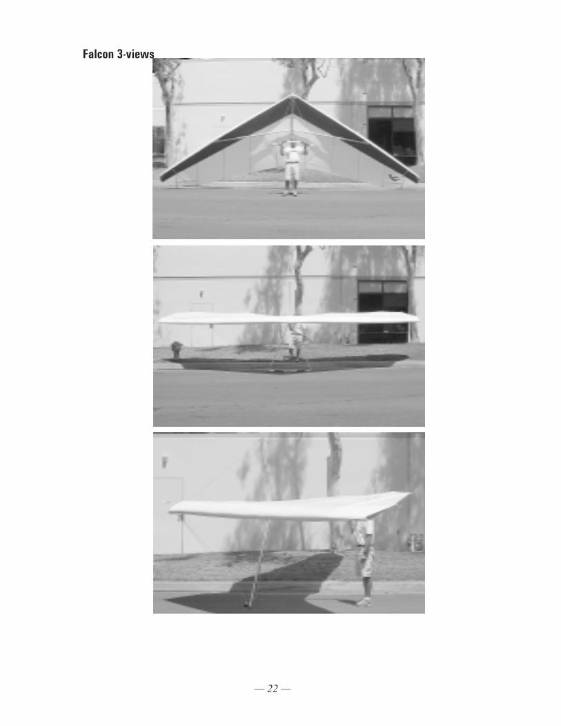
Falcon 3-views
— 23 —
Launching And Flying The Falcon1. If the wind is more than 10 mph or gusty you should have an assistant on your nose wires on
launch, and, if necessary, an assistant on one or both side wires. Make sure all signals are clearly understood. Do a hang check immediately prior to launch. The angle at which you hold the glider should depend on the wind speed and slope of the terrain at launch; you want to achieve a slight positive angle of attack at the start of your run.
2. Run aggressively on launch and ease the bar out for lift off.
3. The flying characteristics of the Falcon are typical of a medium performance flex wing. Make your first flights from a familiar site in mellow conditions to give you time to become accustomed to the glider.
4. We recommend that you hang as close as possible to the basetube in the glider - this will give you lighter control pressures and better control.
Using Wing TuftsYour Wills Wing glider has been equipped from the factory with short yarn tufts on the top surface of each wing. The shadow of these tufts will be visible through the sail. The tufts are useful for indicat-ing the local reversal of the airflow which is associated with the onset of the stall in that portion of the wing. You can use these tufts, as described below, to help determine when you are flying at minimum sink airspeed.
There are two important airspeeds with which all hang glider pilots should be intimately familiar; minimum sink airspeed (hereinafter referred to as VMS) and minimum controllable airspeed (MCA). The most important of these two is MCA. Minimum sink airspeed is that speed at which your descent rate is the slowest possible. It is the speed to fly when you want to maximize your climb rate in lift, or slow your rate of descent to a minimum in non lifting air. (You would normally not fly at VMS in sinking air; the strategy there is normally to speed up and fly quickly out of the sink. By minimiz-ing your time spent in the sinking air you minimize altitude lost, even though you have momentarily increased your sink rate by speeding up.)
Minimum controllable airspeed is that speed below which you begin to rapidly lose effective lateral control of the glider. Recognition of this speed and its implications is a more subtle problem than many pilots realize. We have seen several instances of pilots who were having a lot of trouble flying their gliders simply because they were unknowingly trying to fly them too slowly; below the speed at which the glider responded effectively to lateral control inputs. It is our opinion that a great percent-age of hang gliding accidents are caused by inadvertent flight below MCA, and subsequent loss of control of the glider with impact preceding recovery. Such incidents are usually attributed to “stalls,” but it is not the stall per se that causes the problem, indeed the glider need not even be “stalled” in the traditional sense.
There is no necessary cause and effect relationship between minimum sink speed and minimum controllable airspeed. VMS is determined primarily by the wing loading and span loading, the wing planform, the wing section characteristics, etc. MCA is influenced most heavily by the tension in the sail; how much “billow” the glider has. However, in your Wills Wing glider, as in most hang gliders, MCA and VMS evolved towards a common value during the design and development of the glider. This is so because if the wing is tuned so tight that minimum controllable airspeed is at a higher speed
— 24 —
than minimum sink speed, then effective sink rate performance can be improved by loosening the wing so as to lower the minimum controllable airspeed. Conversely, if minimum controllable airspeed is reached at a speed below that of minimum sink, the wing can usually be tightened so as to improve glide performance without significant sacrifice in other areas.
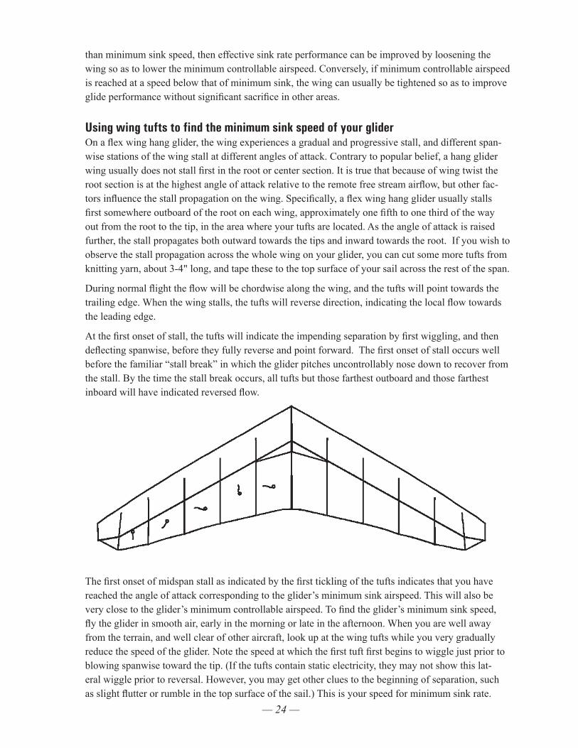
Using wing tufts to find the minimum sink speed of your gliderOn a flex wing hang glider, the wing experiences a gradual and progressive stall, and different span-wise stations of the wing stall at different angles of attack. Contrary to popular belief, a hang glider wing usually does not stall first in the root or center section. It is true that because of wing twist the root section is at the highest angle of attack relative to the remote free stream airflow, but other fac-tors influence the stall propagation on the wing. Specifically, a flex wing hang glider usually stalls first somewhere outboard of the root on each wing, approximately one fifth to one third of the way out from the root to the tip, in the area where your tufts are located. As the angle of attack is raised further, the stall propagates both outward towards the tips and inward towards the root. If you wish to observe the stall propagation across the whole wing on your glider, you can cut some more tufts from knitting yarn, about 3-4" long, and tape these to the top surface of your sail across the rest of the span.
During normal flight the flow will be chordwise along the wing, and the tufts will point towards the trailing edge. When the wing stalls, the tufts will reverse direction, indicating the local flow towards the leading edge.
At the first onset of stall, the tufts will indicate the impending separation by first wiggling, and then deflecting spanwise, before they fully reverse and point forward. The first onset of stall occurs well before the familiar “stall break” in which the glider pitches uncontrollably nose down to recover from the stall. By the time the stall break occurs, all tufts but those farthest outboard and those farthest inboard will have indicated reversed flow.
The first onset of midspan stall as indicated by the first tickling of the tufts indicates that you have reached the angle of attack corresponding to the glider’s minimum sink airspeed. This will also be very close to the glider’s minimum controllable airspeed. To find the glider’s minimum sink speed, fly the glider in smooth air, early in the morning or late in the afternoon. When you are well away from the terrain, and well clear of other aircraft, look up at the wing tufts while you very gradually reduce the speed of the glider. Note the speed at which the first tuft first begins to wiggle just prior to blowing spanwise toward the tip. (If the tufts contain static electricity, they may not show this lat-eral wiggle prior to reversal. However, you may get other clues to the beginning of separation, such as slight flutter or rumble in the top surface of the sail.) This is your speed for minimum sink rate.
— 25 —
Familiarize yourself with the position of the control bar relative to your body at this speed, with the sound and feel of the wind, with the reading on your airspeed indicator, and with the feel of the glider in terms of pitch and roll pressures. Most of the time when you are flying it will not be practical to look up for extended periods of time at your tufts. That is why familiarization with these other, more accessible indicators is important.
After finding your minimum sink speed, experiment with roll control response at speeds just above and just below this speed to find the value of MCA and the corresponding bar position and other indicators for this speed. Realize that your effective MCA is going to be higher and higher as the air becomes more and more turbulent; control response that is perfectly adequate in smooth air will not be good enough in rougher air. Try flying the glider with the midspan tufts fully reversed; you will probably find that the glider is somewhat controllable, but only with a lot of physical effort. Note that both MCA and VMS come well before the glider actually “stalls” in the traditional sense, i.e. pitches uncontrollably nose down. You may also be able to sense, or your vario may tell you that although the glider has not “stalled” (pitched nose down) your sink rate has increased significantly. In this mode the glider is “mushing.”
Once you have familiarized yourself with the glider’s characteristics in this range of speeds, you will not need to look at the tufts very often. You will know from bar position and bar pressure, and from the sound and feel of the relative wind when you are at your minimum sink / minimum controllable airspeed. In general, you should not fly your glider below this speed. Be aware, however, that when you are flying at minimum sink in thermal gusts and turbulence, you will experience gust induced separation of the airflow which will periodically cause the tufts on your sail to reverse.
Of course in a turn, your minimum sink speed goes up because you are banked, and the bank effec-tively increases your wing loading which increases your flying speed for any angle of attack. But note this: The tufts indicate angle of attack, without regard to airspeed! Therefore, if you practice flying various bank angles in smooth air (while well away from any terrain or other gliders) and watch your tufts (on the inside wing, which will be at the highest angle of attack) you will get a feel for the way your minimum sink speed varies at varying bank angles.
One final caution: from time to time a tuft may to stick completely to the sail, and fail to properly indicate the direction of local flow. This may result from static buildup, or from the fine threads of the yard becoming caught on a seam or some dirt or imperfection in the sail. The tuft may stick while in-dicating normal flow, but most often it will stick after having reversed, such that the tuft will indicate a stalled condition that does not exist. One clue in this situation is to note whether or not the tuft is wiggling. Since flow reversal occurs during a turbulent separated flow, a reversed tuft should be wig-gling rapidly. If it is not, it is probably stuck. A tuft indicating normal flow will not usually wiggle. An occasional application of silicone spray to the tufts, and making sure that they are positioned so that they cannot catch on any seam will minimize the problem of sticking.
— 26 —
Trimming Your Glider In PitchThe fore and aft location along the keel of your hang point is commonly (if mistakenly) referred to as your “CG location.” The location of this hang point will, all other things being equal, determine at what angle of attack and airspeed your glider will naturally tend to fly (or trim), and therefore how much bar pressure there is to pull in from trim to a given faster speed, or how much pressure there is to push out from trim to a given slower speed. The farther forward your hang point is, the faster the glider will trim, the less effort will be required to fly fast, and the more effort will be required to fly slow. Since the Falcon performs best at speeds relatively close to VMS, it is usually best to trim the glider at between minimum sink airspeed and perhaps 3 mph above that.
The pre-set factory position for the main hang loop is:
Falcon 3 145, 170 2.5 inches forward of the horizontal apex bolt Falcon 4 145, 170
Falcon 3 195 3.25 inches forward of the horizontal apex bolt Flaocn 4 195
Falcon 3 Tandem For tandem flight, 3.25 inches forward of the horizontal apex bolt For solo flight, 2.75 inches forward of the horizontal apex bolt
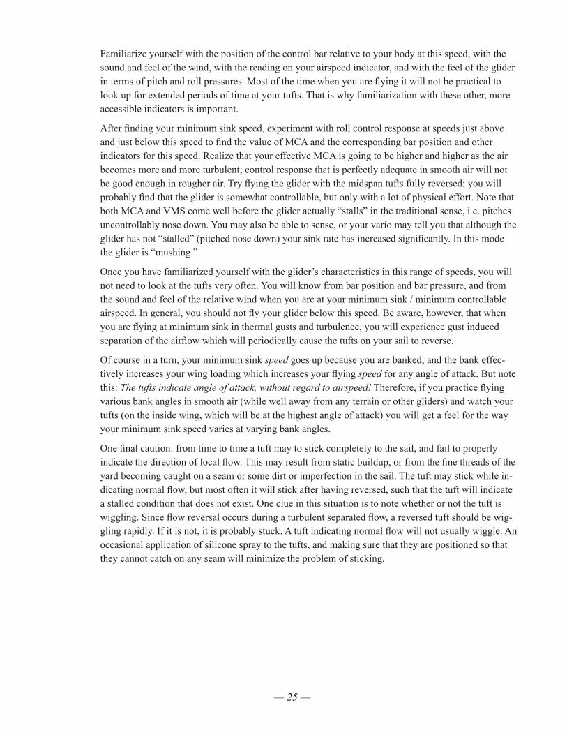
Hang loop fore and aft position is adjusted by loosening the Velcro cinch strap on the main hang loop, repositioning the loop as desired, and retightening the cinch strap. This strap must be very tight to insure that the hang strap does not move during set up and breakdown, or in flight. To tighten the Velcro, grasp the hanging portion of the hang strap with your left hand and pull down while push-ing up with your left thumb on the Velcro cinch strap where it passes through the top end of the hang loop. At the same time, pull up vigorously on the cinch strap and press it into place against the mating Velcro surface.
Hang loop mustbe passedthrough itself.
Move hang loop towardstail to reduce trim speed
Velcro is usedto cinch loop tightly to keel.
Hang loop must becentered on bottomof keel when velcrois fully cinched.
(Back up loop not shown)
Move hang loop towardsnose to increase trim speed

— 27 —
We recommend that you not stow your glider bag, or any other cargo on the glider. The practice of attaching your glider bag to the keel, for example, can drastically alter the pitch trim and static balance of your glider, and adversely affect its flying and landing characteristics. The best place to carry your glider bag or other cargo is in your harness.
In the absence of the use of tufts, it has become common for pilots to talk about bar position, or about indicated airspeed, when trying to communicate how to trim a glider properly or how to fly a glider at the proper speed for a given situation. The problem is that these methods are unreliable and inconsis-tent from one pilot to another even on the same glider. The angle at which your harness suspends your body in your glider has a great deal to do with your perception of the bar “position” relative to your body. Airspeed indicators vary in their indicated airspeed depending on the make of the instrument, its calibration, any installation error, etc. The use of tufts gives you an absolute first hand indication of the actual aerodynamic event associated with two critically important airspeeds on your glider. It is a potentially useful tool that may improve your flying.
— 28 —
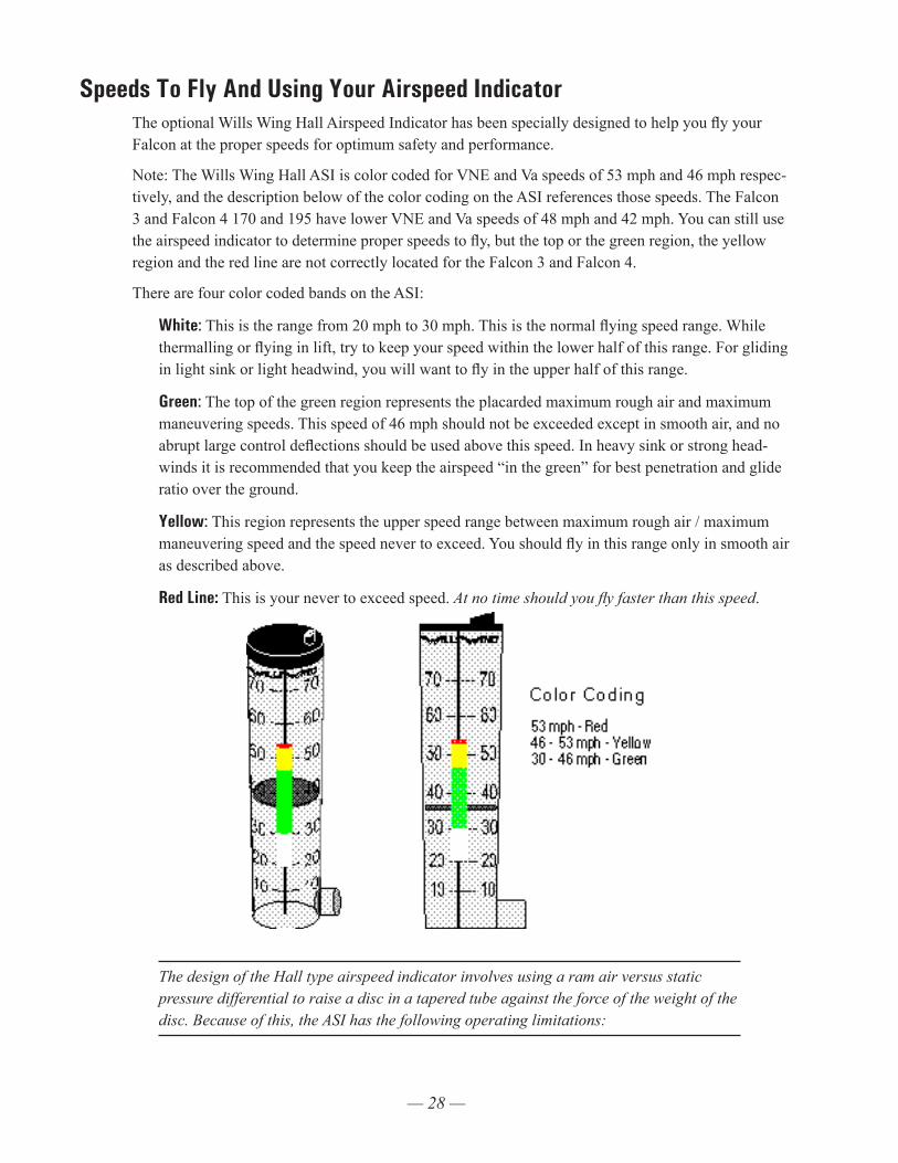
Speeds To Fly And Using Your Airspeed IndicatorThe optional Wills Wing Hall Airspeed Indicator has been specially designed to help you fly your Falcon at the proper speeds for optimum safety and performance.
Note: The Wills Wing Hall ASI is color coded for VNE and Va speeds of 53 mph and 46 mph respec-tively, and the description below of the color coding on the ASI references those speeds. The Falcon 3 and Falcon 4 170 and 195 have lower VNE and Va speeds of 48 mph and 42 mph. You can still use the airspeed indicator to determine proper speeds to fly, but the top or the green region, the yellow region and the red line are not correctly located for the Falcon 3 and Falcon 4.
There are four color coded bands on the ASI:
White: This is the range from 20 mph to 30 mph. This is the normal flying speed range. While thermalling or flying in lift, try to keep your speed within the lower half of this range. For gliding in light sink or light headwind, you will want to fly in the upper half of this range.
Green: The top of the green region represents the placarded maximum rough air and maximum maneuvering speeds. This speed of 46 mph should not be exceeded except in smooth air, and no abrupt large control deflections should be used above this speed. In heavy sink or strong head-winds it is recommended that you keep the airspeed “in the green” for best penetration and glide ratio over the ground.
Yellow: This region represents the upper speed range between maximum rough air / maximum maneuvering speed and the speed never to exceed. You should fly in this range only in smooth air as described above.
Red Line: This is your never to exceed speed. At no time should you fly faster than this speed.
The design of the Hall type airspeed indicator involves using a ram air versus static pressure differential to raise a disc in a tapered tube against the force of the weight of the disc. Because of this, the ASI has the following operating limitations:
— 29 —
a. It is only accurate in one G flight. If you are turning at a bank angle of more than 30 degrees, the ASI will read artificially low as a result of the G loading of the turn. Reliance on the ASI for limiting airspeeds in high banked sustained spiral maneuvers will likely cause you to exceed the placarded speed limitations of the glider and will compromise your safety.
b. It is only accurate when within 15-20 degrees of the vertical orientation.
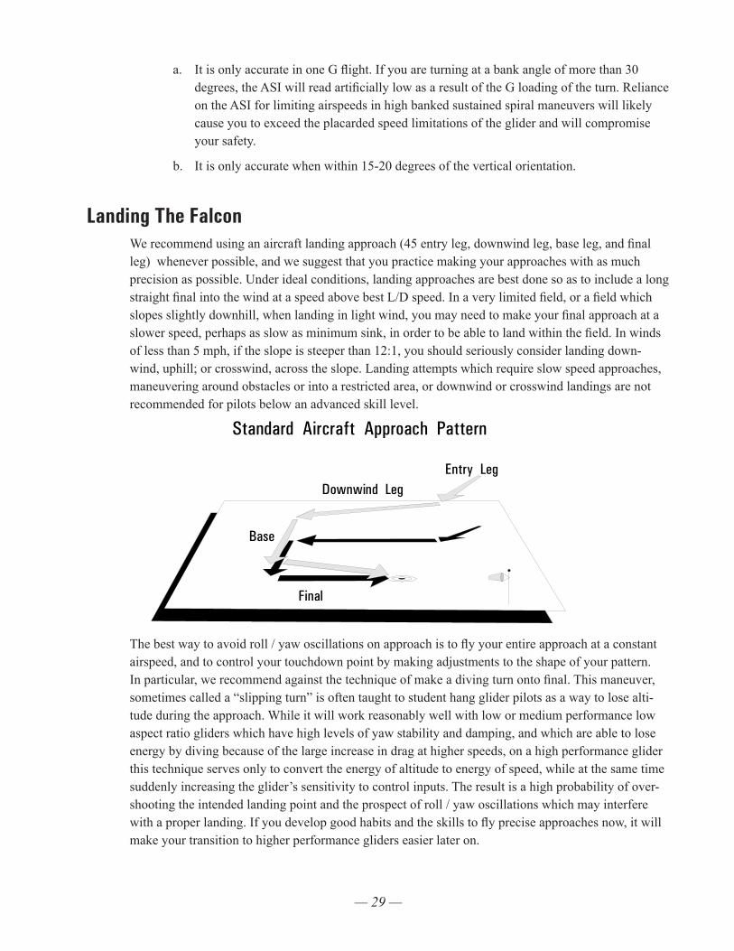
Landing The FalconWe recommend using an aircraft landing approach (45 entry leg, downwind leg, base leg, and final leg) whenever possible, and we suggest that you practice making your approaches with as much precision as possible. Under ideal conditions, landing approaches are best done so as to include a long straight final into the wind at a speed above best L/D speed. In a very limited field, or a field which slopes slightly downhill, when landing in light wind, you may need to make your final approach at a slower speed, perhaps as slow as minimum sink, in order to be able to land within the field. In winds of less than 5 mph, if the slope is steeper than 12:1, you should seriously consider landing down-wind, uphill; or crosswind, across the slope. Landing attempts which require slow speed approaches, maneuvering around obstacles or into a restricted area, or downwind or crosswind landings are not recommended for pilots below an advanced skill level.
Standard Aircraft Approach Pattern
Entry LegDownwind Leg
Base
Final
The best way to avoid roll / yaw oscillations on approach is to fly your entire approach at a constant airspeed, and to control your touchdown point by making adjustments to the shape of your pattern. In particular, we recommend against the technique of make a diving turn onto final. This maneuver, sometimes called a “slipping turn” is often taught to student hang glider pilots as a way to lose alti-tude during the approach. While it will work reasonably well with low or medium performance low aspect ratio gliders which have high levels of yaw stability and damping, and which are able to lose energy by diving because of the large increase in drag at higher speeds, on a high performance glider this technique serves only to convert the energy of altitude to energy of speed, while at the same time suddenly increasing the glider’s sensitivity to control inputs. The result is a high probability of over-shooting the intended landing point and the prospect of roll / yaw oscillations which may interfere with a proper landing. If you develop good habits and the skills to fly precise approaches now, it will make your transition to higher performance gliders easier later on.
— 30 —
Once established on a straight final approach, with wings level and flying directly into the wind, you should fly the glider down to where the basetube is between three and six feet off the ground. At this altitude, let the control bar out just enough “round out” so that your descent is arrested and your flight path parallels the ground. The remainder of your approach will consist of bleeding off excess speed while paralleling the ground and keeping the wings level and the nose into the wind until it is time to “flare” for landing.
Prior to the landing flare your body position should be generally upright, but slightly inclined for-ward, with your head and shoulders forward of your hips and your legs and feet trailing slightly behind. Your hands should be at shoulder width and shoulder height on the uprights. You should be relaxed, with a light grip on the bar, and your weight should be fully supported in your harness and not at all by your arms. There are several options for when to make the transition from prone to this semi-upright position. Some pilots favor going upright with both hands moving to the downtubes while still at altitude prior to the start of the approach. Others transition at the start of the approach to a semi-upright position with one hand on a downtube and one hand on the basetube, and complete the transition by moving the other hand to the downtube just a few seconds prior to flare. Still others fly with both hands on the basetube until established on final glide, and then transition one hand at a time to the downtubes prior to flare.
Whichever method you use, there are a few important principles to observe. The first is that you should not make any change in hand position unless you are flying at or very near trim speed. At speeds faster than trim, you will be holding the bar in pitch against substantial force, and if you let go to move your hand the glider will pitch up and roll towards your remaining hand. The second is that while moving either hand, you have no control over the glider. You should move only one hand at a time. Even so, if you can’t make the transition in the position of each hand quickly and reliably, you should transition both hands while at altitude, before you start your approach. Otherwise, if you fail to make a quick transition, you could be out of control close to the ground, and suffer a turbulence in-duced change in heading or attitude without sufficient time to recover. Many pilots make the mistake of trying to change position while flying fast and close to the ground, and experience a dangerous loss of control as a result. A third principle to observe is that if you are using a “pod” type harness, you should unzip and confirm that your legs are free to exit the harness at least 500 feet above the ground and before you start your approach. If there is any problem finding the zipper pull, or dealing with a stuck zipper, you don’t want to have to try to fix that problem while also flying the approach.
Finally, you should not attempt to get into a fully upright body position at any time during the landing approach prior to the actual landing flare. Most modern harnesses will not allow you to hang in a fully upright position without pulling yourself up on the downtubes, and this is something you should NOT do. The mechanism by which you attain an upright position at the moment of touchdown is to ex-ecute a strong flare, which causes the glider to slow abruptly, causing you to swing forward and into a standing, upright position underneath the glider. The more upright you try to be prior to the flare, the more you move your shoulders back relative to the center of mass of your body, which effectively shortens your arms and weakens your flare authority. Keep your head and shoulders forward, and your feet and legs back, with your body in a semi upright position, until it is time to flare, and then flare from this position.
Once established on a wings level short final, into the wind, body semi-upright and with both hands on the downtubes, your final concern is the timing and execution of the landing flare. The goal is to arrive on the ground, on your feet, under control with the glider settling on your shoulders. If the wind
— 31 —
is 15 mph or more, you will not really execute a flare at all; you will simply slow to minimum flying speed, put a foot down, and step onto the ground. In lighter winds, you will want to use some combi-nation of a final nose up flare, and running out your landing, in order to finish the flight on your feet with the glider settling on your shoulders. The lighter the wind, the stronger should be both your flare and your run.
The traditional method of landing in light or no wind calls for a sharp, aggressive flare at precisely the correct moment. This technique works fine when done correctly, but it’s not easy to get the timing just right. Flare too early and you will climb, and then fall with the nose pitching down. Flare too late and you won’t get the nose up enough to stop your forward motion, and the glider may nose into the ground as you run into it from behind.
The flare timing process is made much easier by using a combination of a “crescendo flare” and a run out of the landing. As you bleed off speed on final, flying just above the ground, you are at first letting the control bar out towards its trim position. As the glider reaches trim speed, which will normally be one to three mph above stall speed, you begin to gently push the bar out to keep the glider from settling. At this point it is almost time to flare. As the glider enters the “mushing” range of angles of attack, it will begin to settle in spite of your continuing to ease the bar out. This should be hap-pening well before your arms are significantly extended. At this point begin your flare by smoothly accelerating the rate at which you push out on the bar. At the same time, draw one leg forward, put a foot down, and start to run as hard as you can. This run should be very much like an aggressive take off run – your body should be leaning forward into the run and you should be driving with your legs. The difference here is that while you are leaning into your run and driving forward with your legs, your arms are extending fully from your shoulders, pushing out, and what feels like upwards, on the control bar in an accelerating, “crescendo” flare.
Done correctly, this type of flare / run combination will bring the glider quickly to a very nose high attitude, producing a great deal of drag and quickly arresting all of your forward motion. You will feel the glider pulling you from behind, resisting your attempt to run, and as you slow down the glider will settle gently on your shoulders. Even in no wind, you should not have to take more than a few steps. If your timing is a little early, and you feel the glider start to climb, simply stop pushing out and resume the flare when the glider again begins to settle. If your timing is a little late, your feet will touch down a little sooner, but as long as you’re running and flaring at the same time, the glider will stay over your head or behind you.
Note: Landing in a significant wind does not require a substantial landing flare; the pilot merely slows to near zero ground speed and touches down. The proper flare in light or no wind conditions is a dynamic action which causes a sudden and severe pitch up rotation of the glider. Pilots who have trouble with the flare, and with the glider nosing over during landing, usually do so because of one of the following problems:
— 32 —
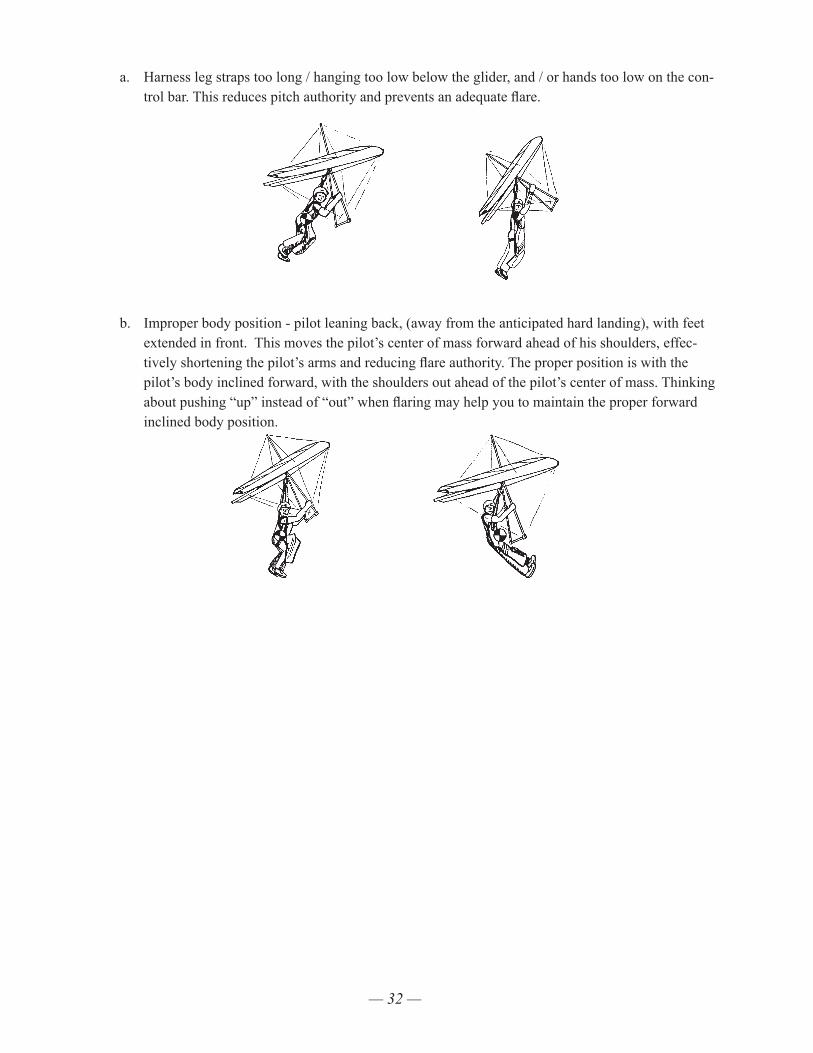
a. Harness leg straps too long / hanging too low below the glider, and / or hands too low on the con-trol bar. This reduces pitch authority and prevents an adequate flare.
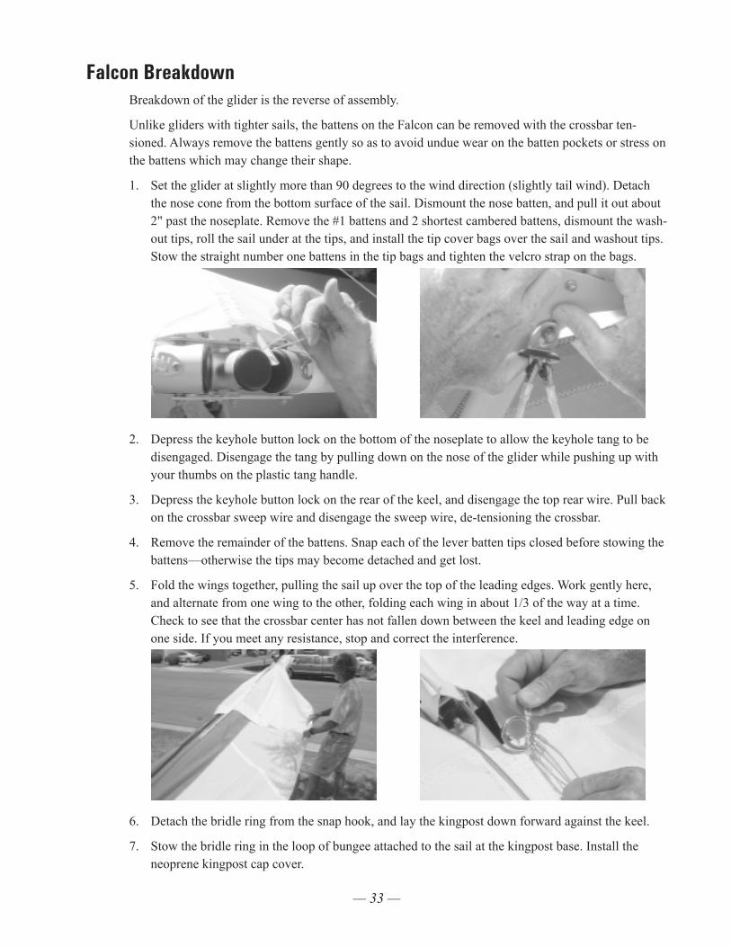
b. Improper body position - pilot leaning back, (away from the anticipated hard landing), with feet extended in front. This moves the pilot’s center of mass forward ahead of his shoulders, effec-tively shortening the pilot’s arms and reducing flare authority. The proper position is with the pilot’s body inclined forward, with the shoulders out ahead of the pilot’s center of mass. Thinking about pushing “up” instead of “out” when flaring may help you to maintain the proper forward inclined body position.
— 33 —
Falcon BreakdownBreakdown of the glider is the reverse of assembly.
Unlike gliders with tighter sails, the battens on the Falcon can be removed with the crossbar ten-sioned. Always remove the battens gently so as to avoid undue wear on the batten pockets or stress on the battens which may change their shape.
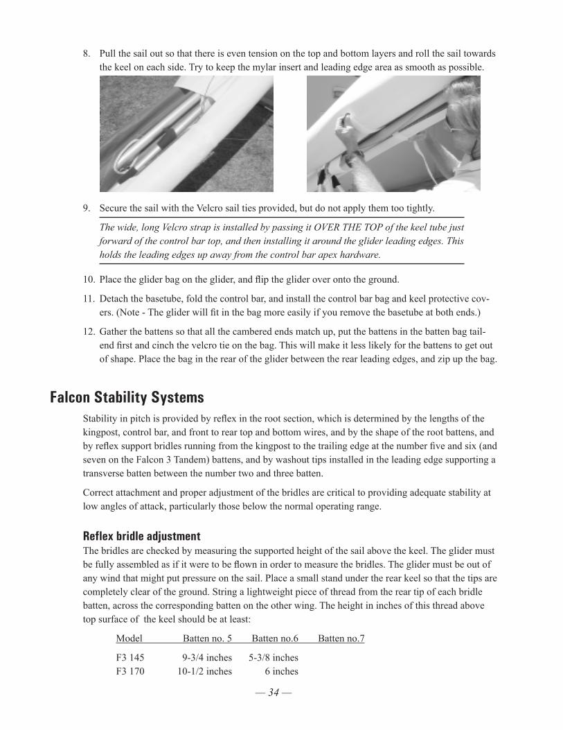
1. Set the glider at slightly more than 90 degrees to the wind direction (slightly tail wind). Detach the nose cone from the bottom surface of the sail. Dismount the nose batten, and pull it out about 2" past the noseplate. Remove the #1 battens and 2 shortest cambered battens, dismount the wash-out tips, roll the sail under at the tips, and install the tip cover bags over the sail and washout tips. Stow the straight number one battens in the tip bags and tighten the velcro strap on the bags.
2. Depress the keyhole button lock on the bottom of the noseplate to allow the keyhole tang to be disengaged. Disengage the tang by pulling down on the nose of the glider while pushing up with your thumbs on the plastic tang handle.
3. Depress the keyhole button lock on the rear of the keel, and disengage the top rear wire. Pull back on the crossbar sweep wire and disengage the sweep wire, de-tensioning the crossbar.
4. Remove the remainder of the battens. Snap each of the lever batten tips closed before stowing the battens—otherwise the tips may become detached and get lost.
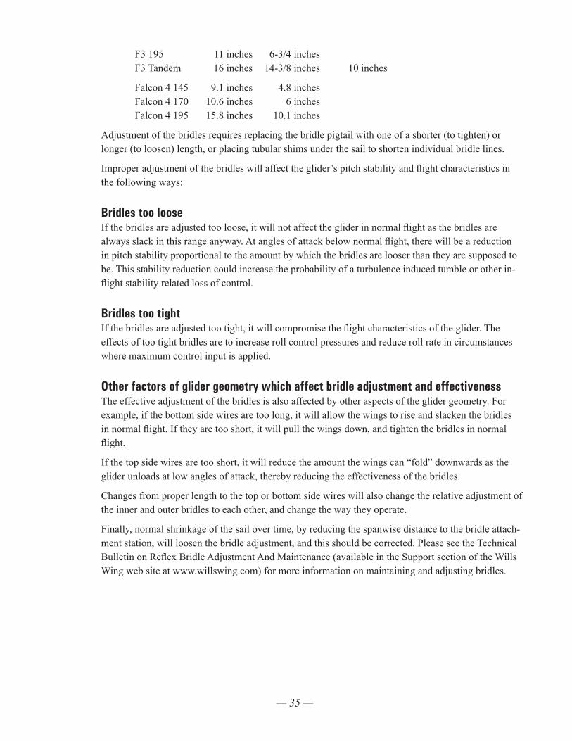
5. Fold the wings together, pulling the sail up over the top of the leading edges. Work gently here, and alternate from one wing to the other, folding each wing in about 1/3 of the way at a time. Check to see that the crossbar center has not fallen down between the keel and leading edge on one side. If you meet any resistance, stop and correct the interference.
6. Detach the bridle ring from the snap hook, and lay the kingpost down forward against the keel.
7. Stow the bridle ring in the loop of bungee attached to the sail at the kingpost base. Install the neoprene kingpost cap cover.
— 34 —
8. Pull the sail out so that there is even tension on the top and bottom layers and roll the sail towards the keel on each side. Try to keep the mylar insert and leading edge area as smooth as possible.
9. Secure the sail with the Velcro sail ties provided, but do not apply them too tightly.
The wide, long Velcro strap is installed by passing it OVER THE TOP of the keel tube just forward of the control bar top, and then installing it around the glider leading edges. This holds the leading edges up away from the control bar apex hardware.
10. Place the glider bag on the glider, and flip the glider over onto the ground.
11. Detach the basetube, fold the control bar, and install the control bar bag and keel protective cov-ers. (Note - The glider will fit in the bag more easily if you remove the basetube at both ends.)
12. Gather the battens so that all the cambered ends match up, put the battens in the batten bag tail-end first and cinch the velcro tie on the bag. This will make it less likely for the battens to get out of shape. Place the bag in the rear of the glider between the rear leading edges, and zip up the bag.
Falcon Stability SystemsStability in pitch is provided by reflex in the root section, which is determined by the lengths of the kingpost, control bar, and front to rear top and bottom wires, and by the shape of the root battens, and by reflex support bridles running from the kingpost to the trailing edge at the number five and six (and seven on the Falcon 3 Tandem) battens, and by washout tips installed in the leading edge supporting a transverse batten between the number two and three batten.
Correct attachment and proper adjustment of the bridles are critical to providing adequate stability at low angles of attack, particularly those below the normal operating range.
Reflex bridle adjustmentThe bridles are checked by measuring the supported height of the sail above the keel. The glider must be fully assembled as if it were to be flown in order to measure the bridles. The glider must be out of any wind that might put pressure on the sail. Place a small stand under the rear keel so that the tips are completely clear of the ground. String a lightweight piece of thread from the rear tip of each bridle batten, across the corresponding batten on the other wing. The height in inches of this thread above top surface of the keel should be at least:
Model Batten no. 5 Batten no.6 Batten no.7
F3 145 9-3/4 inches 5-3/8 inches F3 170 10-1/2 inches 6 inches
— 35 —
F3 195 11 inches 6-3/4 inches F3 Tandem 16 inches 14-3/8 inches 10 inches
Falcon 4 145 9.1 inches 4.8 inches Falcon 4 170 10.6 inches 6 inches Falcon 4 195 15.8 inches 10.1 inches
Adjustment of the bridles requires replacing the bridle pigtail with one of a shorter (to tighten) or longer (to loosen) length, or placing tubular shims under the sail to shorten individual bridle lines.
Improper adjustment of the bridles will affect the glider’s pitch stability and flight characteristics in the following ways:
Bridles too looseIf the bridles are adjusted too loose, it will not affect the glider in normal flight as the bridles are always slack in this range anyway. At angles of attack below normal flight, there will be a reduction in pitch stability proportional to the amount by which the bridles are looser than they are supposed to be. This stability reduction could increase the probability of a turbulence induced tumble or other in-flight stability related loss of control.
Bridles too tightIf the bridles are adjusted too tight, it will compromise the flight characteristics of the glider. The effects of too tight bridles are to increase roll control pressures and reduce roll rate in circumstances where maximum control input is applied.
Other factors of glider geometry which affect bridle adjustment and effectivenessThe effective adjustment of the bridles is also affected by other aspects of the glider geometry. For example, if the bottom side wires are too long, it will allow the wings to rise and slacken the bridles in normal flight. If they are too short, it will pull the wings down, and tighten the bridles in normal flight.
If the top side wires are too short, it will reduce the amount the wings can “fold” downwards as the glider unloads at low angles of attack, thereby reducing the effectiveness of the bridles.
Changes from proper length to the top or bottom side wires will also change the relative adjustment of the inner and outer bridles to each other, and change the way they operate.
Finally, normal shrinkage of the sail over time, by reducing the spanwise distance to the bridle attach-ment station, will loosen the bridle adjustment, and this should be corrected. Please see the Technical Bulletin on Reflex Bridle Adjustment And Maintenance (available in the Support section of the Wills Wing web site at www.willswing.com) for more information on maintaining and adjusting bridles.

— 36 —
Maintenance ScheduleYou should continually maintain your glider in a proper state of tune and repair to insure optimum air-worthiness, performance and flight characteristics. Failure to properly maintain your glider may lead to a dangerous loss of strength, stability or control responsiveness of the glider. Following any mishap that results in damage to the glider immediately have any damaged component repaired or replaced. We recommend that you have all such maintenance work done by your Wills Wing dealer. In addition, please follow the following maintenance schedule. Maintenance intervals are expressed in terms of calendar months and number of flights. You should perform the indicated maintenance at whichever comes first::
Every month or every 30 flights. 1. Check your battens on a flat level surface following the instructions on the batten diagram pro-
vided, and correct any that deviate from the pattern in accordance with the instructions.
Every six months or every 150 flights1. Have a complete inspection performed on the glider and replace any component that shows any
wear, and any cable that shows any kinks, wear, damage, corrosion, etc.
2. Inspect all bolts for tightness, all safeties for proper installation and possible damage. Inspect plates and fittings for damage, holes in tubes for elongation.
3. Inspect the sail for wear, tears, UV damage, loose stitching, etc.
4. Disassemble the control bar corner assemblies. Inspect the hardware fittings and the cable termi-nations on the front and rear flying wires. Replace any component with indications of permanent deformation or other damage.
Every twelve months or every 300 flights1. Have the sail completely removed from the frame, and disassemble all frame components. Inspect
every part of the glider for any damage or wear. Inspect the tubes for straightness and for signs of corrosion. Anytime you have the sail off the frame inspect all of the batten pockets and batten pocket terminations.
2. Replace bottom side wires and hang loops.
Special circumstances1. Any time you suffer a crash or extremely hard landing you should have an “annual” inspection
done on your glider to insure that you find all damaged parts. If you bend a downtube, carefully inspect all hardware at the top and bottom of the control bar for damage.
2. If your glider is ever exposed to salt water you will need to have the glider completely disassem-bled in accordance with the recommended annual inspection procedure. All frame parts will need to be disassembled, including the removal of all sleeves, flushed liberally with fresh water, dried completely, and treated for corrosion inhibition with LPS-3 or other suitable agent.
3. Cleaning Your Sail - Keeping your sail clean will extend the life of the cloth, however cleaning the sail too often, or scrubbing the sail excessively will accelerate the breakdown of the stabiliz-ing resin in the cloth, and shorten the life of the sail. When cleaning the entire sail you should
— 37 —
generally use only water and a soft brush. You may clean small spots or stains with any commer-cial spot remover that is labeled for use on polyester. Such cleaning agents are available at the supermarket or drug store, or you may order a cleaning solution from Wills Wing through your dealer.
A note about cables and cable maintenance:The cables which support the glider’s airframe are critical components of the glider’s structure, and must be maintained in an air worthy condition. It is a general practice in the design of aircraft struc-tures to design to an ultimate strength of 1.5 times the highest expected load in normal service. Hang glider cables, like other structural components on the glider, are typically designed with a structural safety factor of only about 50% above the expected maximum load. No significant loss in cable strength can be tolerated.
A cable with even a single broken strand must be replaced before the glider is flown again. A cable which has been bent sharply enough to have taken a permanent set (will not lie flat in a straight line when all tension is removed) must also be replaced immediately. If it is not, subsequent tensioning and de-tensioning of the cable will induce fatigue, and the cable will fail. In tests we have conducted, a cable bent one time to 90 degrees, and then loaded to the equivalent of a normal flight load 100 times (corresponding to 100 or fewer flights), failed at only 56% of its original strength.
Some degree of fatigue due to repeated bending of cables is almost unavoidable in an aircraft that is assembled and disassembled with every flight. Bottom side wires are subject to the highest loads in flight, and are therefore the most critical. This is why we recommend that these wires be replaced annually, even if there is no known damage. The requirement for immediate replacement of a cable known to have been bent or otherwise damaged supercedes this annual replacement requirement.
Replacement cables should always be obtained from the factory, or, if not from the factory, from a reliable source known to use proper fabrication procedures. An improperly made cable may appear perfectly OK on visual inspection, but could fail in flight at a load much below the intended design strength of the cable. Even if the replacement cable is obtained from the factory, it should be checked carefully for length against the cable it is replacing, and inspected carefully before being installed.
Removing The Sail From The Airframe And Short Packing The Glider Many maintenance and repair procedures will require the removal of the sail from the frame. In ad-dition, the first step in short packing the glider to its shortest breakdown length is the removal of the sail. Please follow these instructions when removing the sail, short packing the glider, and reinstalling the sail. Please read all the instructions for each operation before beginning.
Note: The short pack procedures below incorporate the use of the optional short pack storage/trans-port container - a specially designed combination box and heavy-duty zippered bag designed to con-tain and protect your glider during storage and transport in the short pack configuration. The container is available through your Wills Wing dealer, or direct from Wills Wing.
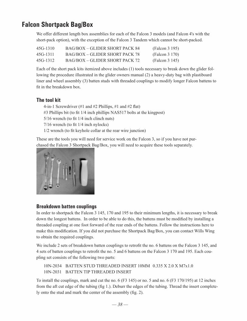
— 38 —
Falcon Shortpack Bag/BoxWe offer different length box assemblies for each of the Falcon 3 models (and Falcon 4's with the short-pack option), with the exception of the Falcon 3 Tandem which cannot be short-packed.
45G-1310 BAG/BOX – GLIDER SHORT PACK 84 (Falcon 3 195) 45G-1311 BAG/BOX – GLIDER SHORT PACK 78 (Falcon 3 170) 45G-1312 BAG/BOX – GLIDER SHORT PACK 72 (Falcon 3 145)
Each of the short pack kits itemized above includes (1) tools necessary to break down the glider fol-lowing the procedure illustrated in the glider owners manual (2) a heavy-duty bag with plastiboard liner and wheel assembly (3) batten studs with threaded couplings to modify longer Falcon battens to fit in the breakdown box.
The tool kit 4-in-1 Screwdriver (#1 and #2 Phillips, #1 and #2 flat)
#3 Phillips bit (to fit 1/4 inch phillips NAS517 bolts at the kingpost) 5/16 wrench (to fit 1/4 inch clinch nuts) 7/16 wrench (to fit 1/4 inch nylocks) 1/2 wrench (to fit keyhole collar at the rear wire junction)
These are the tools you will need for service work on the Falcon 3, so if you have not pur-chased the Falcon 3 Shortpack Bag/Box, you will need to acquire these tools separately.
Breakdown batten couplingsIn order to shortpack the Falcon 3 145, 170 and 195 to their minimum lengths, it is necessary to break down the longest battens. In order to be able to do this, the battens must be modified by installing a threaded coupling at one foot forward of the rear ends of the battens. Follow the instructions here to make this modification. If you did not purchase the Shortpack Bag/Box, you can contact Wills Wing to obtain the required couplings.
We include 2 sets of breakdown batten couplings to retrofit the no. 6 battens on the Falcon 3 145, and 4 sets of batten couplings to retrofit the no. 5 and 6 battens on the Falcon 3 170 and 195. Each cou-pling set consists of the following two parts:
10N-2034 BATTEN STUD THREADED INSERT 10MM 0.335 X 2.0 X M7x1.0 10N-2031 BATTEN TIP THREADED INSERT
To install the couplings, mark and cut the no. 6 (F3 145) or no. 5 and no. 6 (F3 170/195) at 12 inches from the aft cut edge of the tubing (fig 1.). Deburr the edges of the tubing. Thread the insert complete-ly onto the stud and mark the center of the assembly (fig. 2).
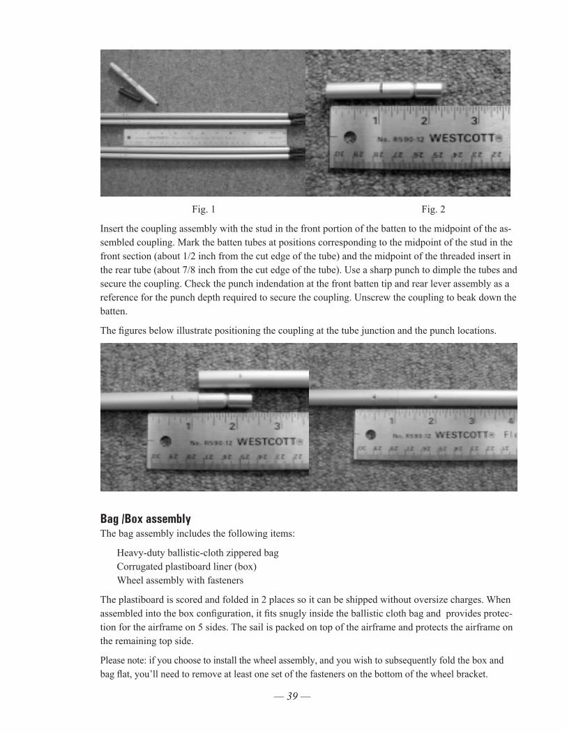
— 39 —
Fig. 1 Fig. 2
Insert the coupling assembly with the stud in the front portion of the batten to the midpoint of the as-sembled coupling. Mark the batten tubes at positions corresponding to the midpoint of the stud in the front section (about 1/2 inch from the cut edge of the tube) and the midpoint of the threaded insert in the rear tube (about 7/8 inch from the cut edge of the tube). Use a sharp punch to dimple the tubes and secure the coupling. Check the punch indendation at the front batten tip and rear lever assembly as a reference for the punch depth required to secure the coupling. Unscrew the coupling to beak down the batten.
The figures below illustrate positioning the coupling at the tube junction and the punch locations.
Bag /Box assembly The bag assembly includes the following items:
Heavy-duty ballistic-cloth zippered bag Corrugated plastiboard liner (box) Wheel assembly with fasteners
The plastiboard is scored and folded in 2 places so it can be shipped without oversize charges. When assembled into the box configuration, it fits snugly inside the ballistic cloth bag and provides protec-tion for the airframe on 5 sides. The sail is packed on top of the airframe and protects the airframe on the remaining top side.
Please note: if you choose to install the wheel assembly, and you wish to subsequently fold the box and bag flat, you’ll need to remove at least one set of the fasteners on the bottom of the wheel bracket.
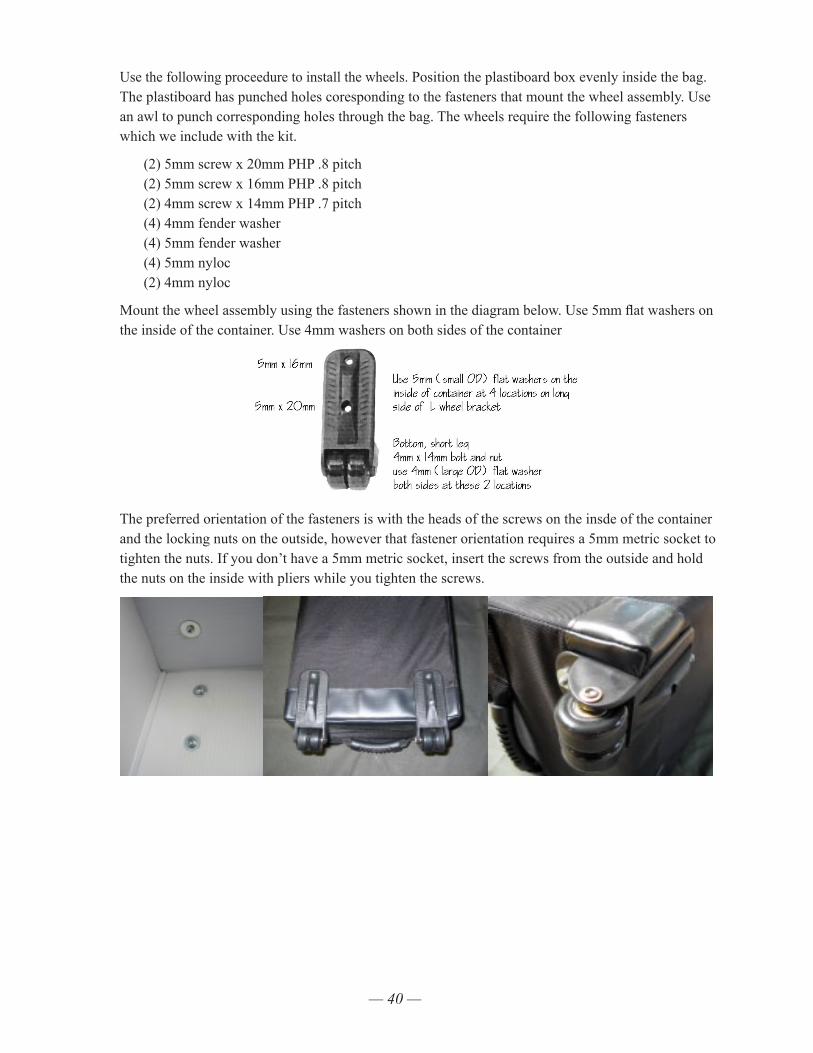
— 40 —
Use the following proceedure to install the wheels. Position the plastiboard box evenly inside the bag. The plastiboard has punched holes coresponding to the fasteners that mount the wheel assembly. Use an awl to punch corresponding holes through the bag. The wheels require the following fasteners which we include with the kit.
(2) 5mm screw x 20mm PHP .8 pitch (2) 5mm screw x 16mm PHP .8 pitch (2) 4mm screw x 14mm PHP .7 pitch (4) 4mm fender washer (4) 5mm fender washer (4) 5mm nyloc (2) 4mm nyloc
Mount the wheel assembly using the fasteners shown in the diagram below. Use 5mm flat washers on the inside of the container. Use 4mm washers on both sides of the container
The preferred orientation of the fasteners is with the heads of the screws on the insde of the container and the locking nuts on the outside, however that fastener orientation requires a 5mm metric socket to tighten the nuts. If you don’t have a 5mm metric socket, insert the screws from the outside and hold the nuts on the inside with pliers while you tighten the screws.
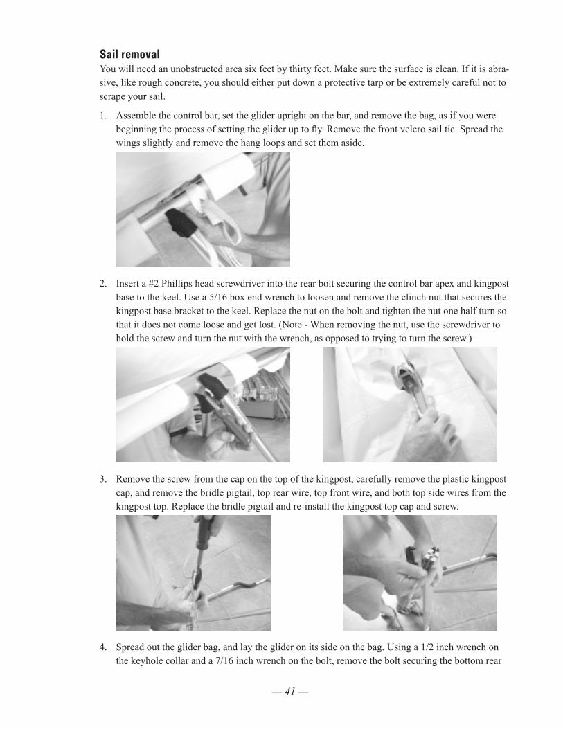
— 41 —
Sail removalYou will need an unobstructed area six feet by thirty feet. Make sure the surface is clean. If it is abra-sive, like rough concrete, you should either put down a protective tarp or be extremely careful not to scrape your sail.
1. Assemble the control bar, set the glider upright on the bar, and remove the bag, as if you were beginning the process of setting the glider up to fly. Remove the front velcro sail tie. Spread the wings slightly and remove the hang loops and set them aside.
2. Insert a #2 Phillips head screwdriver into the rear bolt securing the control bar apex and kingpost base to the keel. Use a 5/16 box end wrench to loosen and remove the clinch nut that secures the kingpost base bracket to the keel. Replace the nut on the bolt and tighten the nut one half turn so that it does not come loose and get lost. (Note - When removing the nut, use the screwdriver to hold the screw and turn the nut with the wrench, as opposed to trying to turn the screw.)
3. Remove the screw from the cap on the top of the kingpost, carefully remove the plastic kingpost cap, and remove the bridle pigtail, top rear wire, top front wire, and both top side wires from the kingpost top. Replace the bridle pigtail and re-install the kingpost top cap and screw.
4. Spread out the glider bag, and lay the glider on its side on the bag. Using a 1/2 inch wrench on the keyhole collar and a 7/16 inch wrench on the bolt, remove the bolt securing the bottom rear
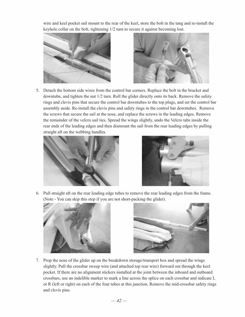
— 42 —
wire and keel pocket sail mount to the rear of the keel, store the bolt in the tang and re-install the keyhole collar on the bolt, tightening 1/2 turn to secure it against becoming lost.
5. Detach the bottom side wires from the control bar corners. Replace the bolt in the bracket and downtube, and tighten the nut 1/2 turn. Roll the glider directly onto its back. Remove the safety rings and clevis pins that secure the control bar downtubes to the top plugs, and set the control bar assembly aside. Re-install the clevis pins and safety rings in the control bar downtubes. Remove the screws that secure the sail at the nose, and replace the screws in the leading edges. Remove the remainder of the velcro sail ties. Spread the wings slightly, undo the Velcro tabs inside the rear ends of the leading edges and then dismount the sail from the rear leading edges by pulling straight aft on the webbing handles.
6. Pull straight aft on the rear leading edge tubes to remove the rear leading edges from the frame. (Note - You can skip this step if you are not short-packing the glider).
7. Prop the nose of the glider up on the breakdown storage/transport box and spread the wings slightly. Pull the crossbar sweep wire (and attached top rear wire) forward out through the keel pocket. If there are no alignment stickers installed at the joint between the inboard and outboard crossbars, use an indelible marker to mark a line across the splice on each crossbar and indicate L or R (left or right) on each of the four tubes at this junction. Remove the mid-crossbar safety rings and clevis pins.
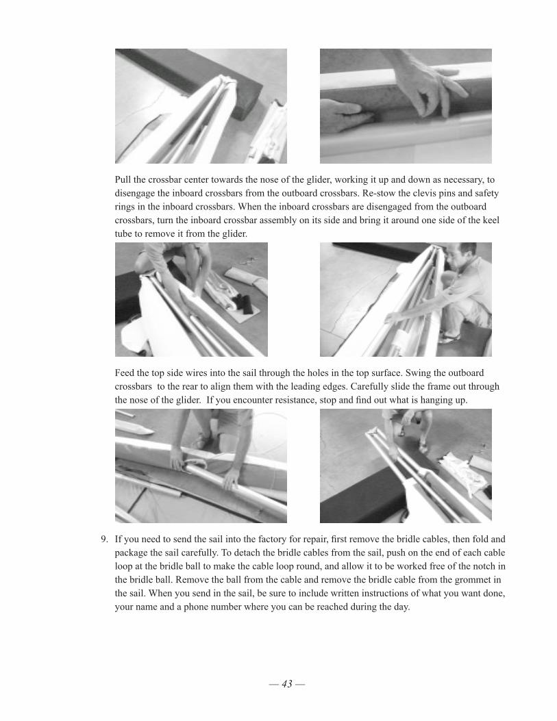
— 43 —
Pull the crossbar center towards the nose of the glider, working it up and down as necessary, to disengage the inboard crossbars from the outboard crossbars. Re-stow the clevis pins and safety rings in the inboard crossbars. When the inboard crossbars are disengaged from the outboard crossbars, turn the inboard crossbar assembly on its side and bring it around one side of the keel tube to remove it from the glider.
Feed the top side wires into the sail through the holes in the top surface. Swing the outboard crossbars to the rear to align them with the leading edges. Carefully slide the frame out through the nose of the glider. If you encounter resistance, stop and find out what is hanging up.
9. If you need to send the sail into the factory for repair, first remove the bridle cables, then fold and package the sail carefully. To detach the bridle cables from the sail, push on the end of each cable loop at the bridle ball to make the cable loop round, and allow it to be worked free of the notch in the bridle ball. Remove the ball from the cable and remove the bridle cable from the grommet in the sail. When you send in the sail, be sure to include written instructions of what you want done, your name and a phone number where you can be reached during the day.
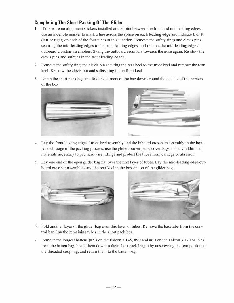
— 44 —
Completing The Short Packing Of The Glider 1. If there are no alignment stickers installed at the joint between the front and mid leading edges,
use an indelible marker to mark a line across the splice on each leading edge and indicate L or R (left or right) on each of the four tubes at this junction. Remove the safety rings and clevis pins securing the mid-leading edges to the front leading edges, and remove the mid-leading edge / outboard crossbar assemblies. Swing the outboard crossbars towards the nose again. Re-stow the clevis pins and safeties in the front leading edges.
2. Remove the safety ring and clevis pin securing the rear keel to the front keel and remove the rear keel. Re-stow the clevis pin and safety ring in the front keel.
3. Unzip the short pack bag and fold the corners of the bag down around the outside of the corners of the box.
4. Lay the front leading edges / front keel assembly and the inboard crossbars assembly in the box. At each stage of the packing process, use the glider's cover pads, cover bags and any additional materials necessary to pad hardware fittings and protect the tubes from damage or abrasion.
5. Lay one end of the open glider bag flat over the first layer of tubes. Lay the mid-leading edge/out-board crossbar assemblies and the rear keel in the box on top of the glider bag.
6. Fold another layer of the glider bag over this layer of tubes. Remove the basetube from the con-trol bar. Lay the remaining tubes in the short pack box.
7. Remove the longest battens (#5’s on the Falcon 3 145, #5’s and #6’s on the Falcon 3 170 or 195) from the batten bag, break them down to their short pack length by unscrewing the rear portion at the threaded coupling, and return them to the batten bag.
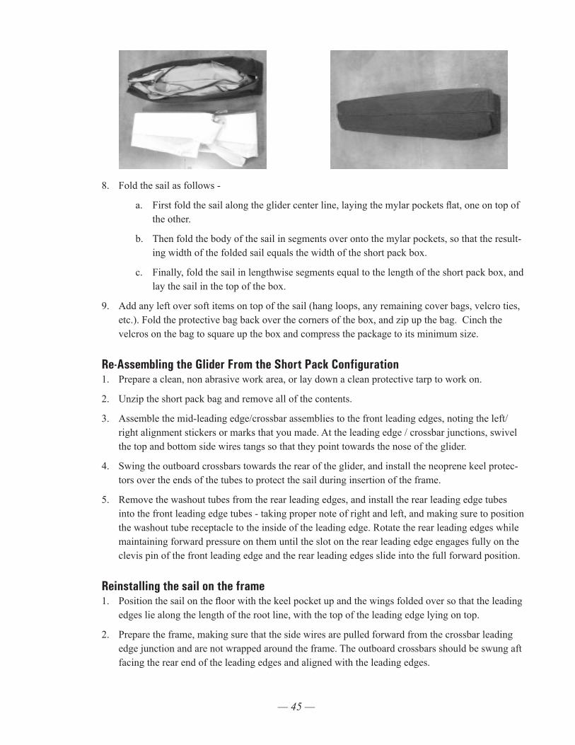
— 45 —
8. Fold the sail as follows -
a. First fold the sail along the glider center line, laying the mylar pockets flat, one on top of the other.
b. Then fold the body of the sail in segments over onto the mylar pockets, so that the result-ing width of the folded sail equals the width of the short pack box.
c. Finally, fold the sail in lengthwise segments equal to the length of the short pack box, and lay the sail in the top of the box.
9. Add any left over soft items on top of the sail (hang loops, any remaining cover bags, velcro ties, etc.). Fold the protective bag back over the corners of the box, and zip up the bag. Cinch the velcros on the bag to square up the box and compress the package to its minimum size.
Re-Assembling the Glider From the Short Pack Configuration 1. Prepare a clean, non abrasive work area, or lay down a clean protective tarp to work on.
2. Unzip the short pack bag and remove all of the contents.
3. Assemble the mid-leading edge/crossbar assemblies to the front leading edges, noting the left/right alignment stickers or marks that you made. At the leading edge / crossbar junctions, swivel the top and bottom side wires tangs so that they point towards the nose of the glider.
4. Swing the outboard crossbars towards the rear of the glider, and install the neoprene keel protec-tors over the ends of the tubes to protect the sail during insertion of the frame.
5. Remove the washout tubes from the rear leading edges, and install the rear leading edge tubes into the front leading edge tubes - taking proper note of right and left, and making sure to position the washout tube receptacle to the inside of the leading edge. Rotate the rear leading edges while maintaining forward pressure on them until the slot on the rear leading edge engages fully on the clevis pin of the front leading edge and the rear leading edges slide into the full forward position.
Reinstalling the sail on the frame1. Position the sail on the floor with the keel pocket up and the wings folded over so that the leading
edges lie along the length of the root line, with the top of the leading edge lying on top.
2. Prepare the frame, making sure that the side wires are pulled forward from the crossbar leading edge junction and are not wrapped around the frame. The outboard crossbars should be swung aft facing the rear end of the leading edges and aligned with the leading edges.
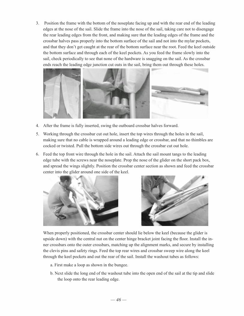
— 46 —
3. Position the frame with the bottom of the noseplate facing up and with the rear end of the leading edges at the nose of the sail. Slide the frame into the nose of the sail, taking care not to disengage the rear leading edges from the front, and making sure that the leading edges of the frame and the crossbar halves pass properly into the bottom surface of the sail and not into the mylar pockets, and that they don’t get caught at the rear of the bottom surface near the root. Feed the keel outside the bottom surface and through each of the keel pockets. As you feed the frame slowly into the sail, check periodically to see that none of the hardware is snagging on the sail. As the crossbar ends reach the leading edge junction cut outs in the sail, bring them out through these holes.
4. After the frame is fully inserted, swing the outboard crossbar halves forward.
5. Working through the crossbar cut out hole, insert the top wires through the holes in the sail, making sure that no cable is wrapped around a leading edge or crossbar, and that no thimbles are cocked or twisted. Pull the bottom side wires out through the crossbar cut out hole.
6. Feed the top front wire through the hole in the sail. Attach the sail mount tangs to the leading edge tube with the screws near the noseplate. Prop the nose of the glider on the short pack box, and spread the wings slightly. Position the crossbar center section as shown and feed the crossbar center into the glider around one side of the keel.
When properly positioned, the crossbar center should lie below the keel (because the glider is upside down) with the central nut on the center hinge bracket joint facing the floor. Install the in-ner crossbars onto the outer crossbars, matching up the alignment marks, and secure by installing the clevis pins and safety rings. Feed the top rear wires and crossbar sweep wire along the keel through the keel pockets and out the rear of the sail. Install the washout tubes as follows:
a. First make a loop as shown in the bungee.
b. Next slide the long end of the washout tube into the open end of the sail at the tip and slide the loop onto the rear leading edge.

— 47 —
c. Pass the washout tube out of the sail through the hole at the receptacle, and position the bungee forward of the washout tube receptacle.
d. Pull the remainder of the washout tube outside of the sail through the hole in the sail at the washout tube receptacle.
7. Verify that the rear leading edges are still properly and fully mounted in the front by first pulling aft no more than 1/4 inch, then pushing them forward until the front leading edge clevis pin bot-toms out in the slot, and then try to twist the rear leading edge to confirm that the slot is engaged and it is locked against rotation. (You will feel some very small amount of rotational play in the slot / pin engagement, but no more than a very small amount.) Mount the rear of the sail by pull-ing the webbing anchor loops over the rear leading edge endcaps and into the slot in the endcaps.
Make sure you mount the inner webbing loops in the endcap slots, not the outer “handle” loops! Make sure that the webbing lies flat and smooth in the slot, and that the sail is properly aligned when mounted (not twisted or rotated 180 degrees). Secure the Velcro retainer tabs. Re-assemble the control bar basetube to the downtubes at this time, taking care to make sure that the basetube and the front and rear wires are properly oriented. Bolt the bottom rear wires to the rear of the keel attaching the rear sail mount at the same time. Install the control bar downtubes onto the plugs at the apex bracket, and attach the bottom side wires to the control bar corners. Flip the glider up onto the control bar.
8. Pull the crossbar sweep wire tang out through the kingpost hole and pull tight on the sweep wire while looking up into the sail towards the crossbar center. Correctly position the left and right sweep wires on the proper sides of the top centerline of the keel.
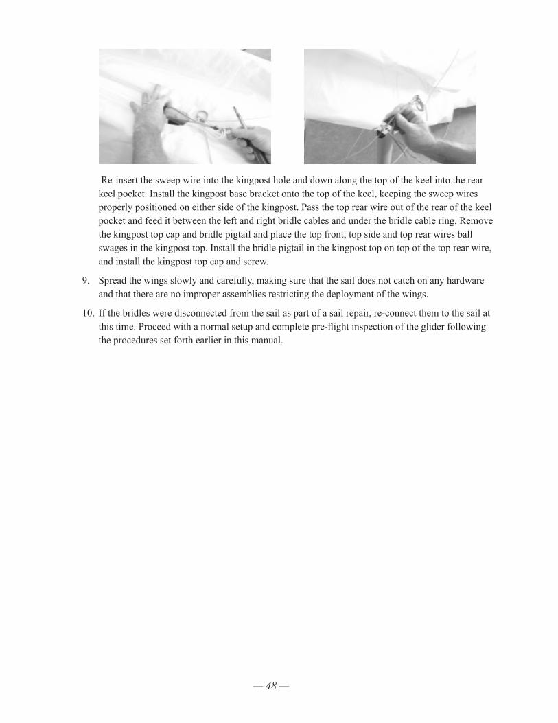
— 48 —
Re-insert the sweep wire into the kingpost hole and down along the top of the keel into the rear keel pocket. Install the kingpost base bracket onto the top of the keel, keeping the sweep wires properly positioned on either side of the kingpost. Pass the top rear wire out of the rear of the keel pocket and feed it between the left and right bridle cables and under the bridle cable ring. Remove the kingpost top cap and bridle pigtail and place the top front, top side and top rear wires ball swages in the kingpost top. Install the bridle pigtail in the kingpost top on top of the top rear wire, and install the kingpost top cap and screw.
9. Spread the wings slowly and carefully, making sure that the sail does not catch on any hardware and that there are no improper assemblies restricting the deployment of the wings.
10. If the bridles were disconnected from the sail as part of a sail repair, re-connect them to the sail at this time. Proceed with a normal setup and complete pre-flight inspection of the glider following the procedures set forth earlier in this manual.

— 49 —
Installing The Optional Litestream Control Bar KitOwners of Falcon 3's and 4's may order an optional Litestream Control Bar kit (the kit is not available for the Falcon 3 Tandem).
We recommend that you have your dealer assist you in the installation of the kit.
The kit consists of:ID Qty Unit Description Appplication
40F-1513 1 EA BASETUBE AL LITSTR W/BRK 65/68 195
40F-1523 1 EA BASETUBE AL LITESTRM W/BRKT 62 170
15J-2201 2 EA STREAMLINED BASETUBE SKID 195/170
10K-3133 2 EA PIN BALL LOCK 1/4 X 33MM GRIP 195/170
40G-1471 2 EA LITESTREAM LEG 65 W/O BRKTS 195
40G-1477 2 EA LITESTREAM LEG 62 W/O BRKTS 170
20G-1467 1 EA CB PLUG SET OF 2 LITESTRM TOP 195/170
20G-1468 1 EA CB PLUG SET OF 2 LITESTRM BTM 195/170
10C-5211 2 EA BOLT NAS 623-4-21 195/170
10N-1740 2 EA CLINCH NUT 1/4 MS21042-4 195/170
10G-1290 4 EA CLEVIS PIN MS20392-2C29 195/170
10P-1100 4 EA SAFETY RING AN 9491 SMALL 195/170
10T-1103 2 EA SPACER AL .250 X .028 X .770 195/170
10T-4120 2 EA BUSH SS .3115 X .028 X .850 195/170
10T-5103 3 EA SPACER NY .560 X .320 X .187 195/170
45G-3058 1 PAIR NEOPRENE COVER SLPSTRM LEG TOP 195/170
Before beginning the installation process, verify that all items above are present. Note that the down-tubes come fully assembled with all hardware attached, and that the items designated 10T-1103 in the above list are installed inside the bottom downtube end plugs.
InstallationThe removal of the round control bar and installation of the Litestream bar can be done with the glider folded up and in the bag, although the glider should be fully set up and a pre-flight inspection performed after the installation.
Removing the round control bar1) Unzip the glider bag. Set the basetube aside.
2) Remove the bolts and nuts that secure the basetube brackets and bottom side wires to the control bar downtubes. Set the brackets, bolts and nuts aside.
3) Remove the safety rings and clevis pins that secure the bottom front and rear wires in the down-tubes, and remove the wires from the downtubes. Set the pins and safety rings aside.
4) Remove the bolts and nuts that secure the downtube top end plugs to the elbows. Set the down-tubes, and the nuts and bolts aside.
5) The parts you have set aside will not be used in the installation of the Litestream bar, but should be retained for re-installation of the round control bar.
— 50 —
Installing the Litestream control bar1) Start by correctly identifying the left and right downtubes. The squared off part of the downtube
profile and the longer bottom wire slots go to the rear, the clevis pins are installed with the heads on the outside and the rings on the inside, and the chord of the profile is “toed-in” relative to the axis of the ¼ inch bolts and ball lock pins in the top and bottom fittings.
2) Install the Litestream downtubes onto the elbows at the control bar apex, using the bolts and nuts provided on the downtubes. Note that on the right downtube, the provided nylon washer goes in front of the control bar elbow.
3) Install the bottom front and bottom rear wires into the respective downtubes as follows:
a) Remove the safety ring and clevis pin and remove the bottom plug from the bottom of the downtube.
b) Taking care not to induce any twisting in the wires, and maintaining the proper orienta-tion of the bottom front wire nose tang, insert the bottom front and bottom rear wires into the back and front slots on the downtube, and pass them out through the bottom of the downtube.
c) Remove the small aluminum spacer from the downtube plug and position the wires in the hollowed area in the bottom of the plug such that they are captured by the spacer when you re-insert it.
d) While sliding the excess wire back out through the slots in the downtube, re-install the plug in the bottom of the downtube, and secure it with the clevis pin and safety ring.
4) Attach the bottom side wires to the downtubes as follows:
a) Remove the knurled bushing from the bottom downtube plug, taking care not to lose the nylon washer.
b) Install the bottom side wire tang and nylon washer into the space between the ears on the downtube bottom plug – taking care that the nylon washer is forward of the side wire tang, that the side wire tang is oriented with the small projection on the tang at the bottom (towards the basetube), that the wires are routed properly and do not cross over or wrap around any other wires or components, and that no twist has been induced in the side wires.
c) Re-install the knurled bushing, knurled portion last, into the bottom downtube plug and press it in until it is flush with the surface of the plug.
5) Install the basetube using the ball lock pins provided, and do a full set up and inspection of the glider.
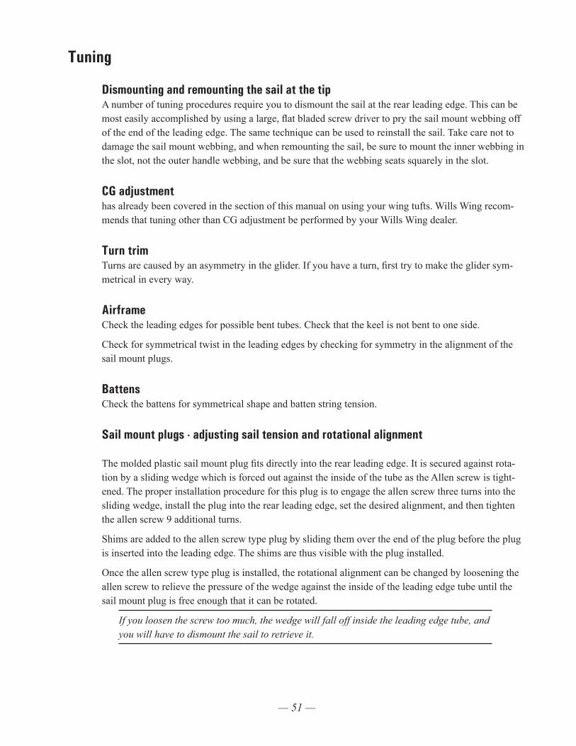
— 51 —
Tuning
Dismounting and remounting the sail at the tipA number of tuning procedures require you to dismount the sail at the rear leading edge. This can be most easily accomplished by using a large, flat bladed screw driver to pry the sail mount webbing off of the end of the leading edge. The same technique can be used to reinstall the sail. Take care not to damage the sail mount webbing, and when remounting the sail, be sure to mount the inner webbing in the slot, not the outer handle webbing, and be sure that the webbing seats squarely in the slot.
CG adjustment has already been covered in the section of this manual on using your wing tufts. Wills Wing recom-mends that tuning other than CG adjustment be performed by your Wills Wing dealer.
Turn trimTurns are caused by an asymmetry in the glider. If you have a turn, first try to make the glider sym-metrical in every way.
AirframeCheck the leading edges for possible bent tubes. Check that the keel is not bent to one side.
Check for symmetrical twist in the leading edges by checking for symmetry in the alignment of the sail mount plugs.
BattensCheck the battens for symmetrical shape and batten string tension.
Sail mount plugs - adjusting sail tension and rotational alignment The molded plastic sail mount plug fits directly into the rear leading edge. It is secured against rota-tion by a sliding wedge which is forced out against the inside of the tube as the Allen screw is tight-ened. The proper installation procedure for this plug is to engage the allen screw three turns into the sliding wedge, install the plug into the rear leading edge, set the desired alignment, and then tighten the allen screw 9 additional turns.
Shims are added to the allen screw type plug by sliding them over the end of the plug before the plug is inserted into the leading edge. The shims are thus visible with the plug installed.
Once the allen screw type plug is installed, the rotational alignment can be changed by loosening the allen screw to relieve the pressure of the wedge against the inside of the leading edge tube until the sail mount plug is free enough that it can be rotated.
If you loosen the screw too much, the wedge will fall off inside the leading edge tube, and you will have to dismount the sail to retrieve it.
— 52 —
Sail tensionCheck for symmetrical sail tension on the leading edges. In order to check this, remove the sail mount screws at the nose, detension and re-tension the xbar and sight the hem of the sail at the bottom of the leading edge tube relative to the noseplate on each side. Sail tension is adjusted by adding or remov-ing shims in 1/8" or 1/4" increments to or from the sail mount plugs on the rear ends of the leading edges. See the discussion above about the different types of sail mount plugs and how shims are added or removed.
To remove or add shims from either plug, first dismount the sail mount webbing by pulling it free and then to the outside of the leading edge. You can use a flat bladed screwdriver to pry the webbing off, but take care not to damage the webbing. After dismounting the sail, first check and record the rotational alignment by noting the position of the scribe mark on the plug relative to the scale on the leading edge tube. Use the allen wrench provided in your spare parts kit to loosen the allen screw until you can remove the plug. Add or remove shims as necessary, and then reinstall the plug, making sure the alignment is correct. Nine turns of the allen screw after installation of the plug will secure the plug in place.
Make sure to replace the sail mount screws at the nose.
Twisting a tip After you have made everything symmetrical, if you still have a turn, you will correct it by rotating one or both sail mount plugs. A left turn is corrected by twisting the left sail plug clockwise (twisting the sail down at the trailing edge) or twisting the right sail plug clockwise (twisting the sail up at the trailing edge) or both. Twist counter clockwise on either or both plugs to correct a right turn.
To rotate the sail plug, use the allen wrench provided in your spare parts kit to loosen the allen screw thus pushing the wedge forward and releasing the plug.
If you loosen the screw too much, the wedge will fall off the end of the screw inside the leading edge, and you will have to dismount the sail to retrieve it. Start by loosening the screw ten turns, and then check to see if you can rotate it. If not, loosen it one turn at a time until it can be rotated.
After rotating the plug in the desired amount in the desired direction, (see above) tighten the screw to secure the plug against rotation. When the screw is properly tightened, there will be a slight bulge (less than the wall thickness of the tube) in the rear leading edge tube adjacent to the screw.
Adjusting batten tensionThe number one and number two tip battens on the Falcon 3 are tensioned by looping the batten string over the notched end of the batten twice. The remainder of the battens are tensioned by the adjust-ment of the lever tip. The inboard battens should be fairly loose, as described in the batten installation portion of the set up procedure. The outboard battens should be progressively more firm. The number one batten strings should be fairly snug, but not so tight as to slacken the sail mount webbing which mounts the sail at the tip. We have found that if the plug on #1 battens are adjusted too tight it can increase the chance that the glider will enter a mild spin when stalled in a turn. If you experience this tendency, try loosening the number one battens slightly.
— 53 —
Leading edge sail tensionThe tension in the leading edge of the sail, adjustable by shimming as described above, will influ-ence the performance and handling of the glider. If the sail is mounted too loose, the performance will deteriorate noticeably. If the sail is mounted too tight, the glider will handle poorly; it will be stiff and slow in roll response with excessive adverse yaw and an increased tendency to spin in a stalled turn. As the glider gets older and the sail stretches, you may need to add shims to maintain the proper ten-sion. Please note that adding shims may reduce the speed at which trailing edge sail flutter begins.
Car Top Mounting And TransportImproper or careless transport of your glider can cause significant damage. You should transport your glider on a rack which has at least three support points which span at least 13' of the length of the glider. These should be well padded and at least four inches wide to distribute the load. Your glider should be mounted on your rack with the control bar facing up. It should be securely tied down with webbing straps which are at least 1/2" wide If you drive on rough roads where the glider receives impact loads, you should take extra care to pad your glider internally when you pack it up. One spe-cial area to pay attention to is the forward area of the glider where the crossbar center section bears against the top of the leading edge tubes, and the kingpost sits on top of the keel. Some extra padding inserted in this area will save wear on your airframe and sail.
In ClosingWith proper care and maintenance, your glider will retain a high level of airworthiness for some years. Because of the relatively short history of hang gliding, and the rapid advances in new designs, we do not have a lot of information about the ultimate service life of a hang glider. We do know that ultraviolet (UV) damage to the sail from sunlight is probably the limiting factor in the life of your sail. Try to avoid exposing your sail to sunlight any time you are not actually flying it.
We also know that there are forces in nature which can be so violent that they can result in fatal accidents regardless of the airworthiness of your aircraft. Ultimately your safety is your responsibil-ity. Know the limitations of your knowledge, skill and experience, and know the limitations of your aircraft. Fly within those limitations.
Have fun.
See you in the sky!
Wills Wing, Inc.

— 54 —
HGMA COMPLIANCE VERIFICATION SPECIFICATION SHEETGLIDER MODEL Falcon 4 145 MANUFACTURED BY Wills Wing Inc.
All dimensions in inches; weights in pounds.NOTE: These specifications are intended only as a guideline for determining whether a
given glider is a certified model and whether it is in the certified configuration.Be aware, however, that no set of specifications, however detailed, can guarantee the
ability to determine whether a glider is the same model, or is in the same configuration as was certified, or has those performance, stability, and structural characteristics required by the certification standards. An owner’s manual is required to be delivered with each HGMA certified glider, and it is required that it contain additional airworthiness informa-tion.
1. Weight of glider with all essential parts and without coverbags and nonessential parts: 45 lbs
2. Leading Edge Dimensionsa. Nose plate anchor hole to:
1. Crossbar attachment hole 109.5 2. Rear sail attachment point 195.5 - 196.25
b. Outside diameter at:1. Nose 2.052. Crossbar 2.05
c. Rear sail attachment point 1.97 3. Crossbar Dimensions
a. Overall pin to pin length from leading edge attachment point to hinge bolt at glider centerline 96.37
b. Largest outside diameter 2.054. Keel dimensions; least and greatest allowable distances, whether variable through
tuning or through in-flight variable geometry, from the line joining the leading edge nose bolts to:a. The xbar center load bearing pin 42.75 +/- .25 b. The pilot hang loop 59.5 +/- 1.5
5. Sail Dimensionsa. Chord lengths at:
1. 3 ft outboard of centerline 77.6 2. 3 ft inboard of tip 46.0
b. Span (extreme tip to tip) 334.26. Location of Information Placard Keel Location of Test Fly Sticker Keel 7. Recommended Pilot Weight Range 120 - 190 8. Recommended Pilot Proficiency USHGA Novice

— 55 —
HGMA COMPLIANCE VERIFICATION SPECIFICATION SHEETGLIDER MODEL Falcon 4 170 MANUFACTURED BY Wills Wing Inc.
All dimensions in inches; weights in pounds.NOTE: These specifications are intended only as a guideline for determining whether a
given glider is a certified model and whether it is in the certified configuration.Be aware, however, that no set of specifications, however detailed, can guarantee the
ability to determine whether a glider is the same model, or is in the same configuration as was certified, or has those performance, stability, and structural characteristics required by the certification standards. An owner’s manual is required to be delivered with each HGMA certified glider, and it is required that it contain additional airworthiness informa-tion.
1. Weight of glider with all essential parts and without coverbags and nonessential parts: 48 lbs
2. Leading Edge Dimensionsa. Nose plate anchor hole to:
1. Crossbar attachment hole 119.5 2. Rear sail attachment point 209.25 - 210
b. Outside diameter at:1. Nose 2.052. Crossbar 2.053. Rear sail attachment point 1.97
3. Crossbar Dimensionsa. Overall pin to pin length from leading edge attachment point to hinge bolt at
glider centerline 105b. Largest outside diameter 2.05
4. Keel dimensions; least and greatest allowable distances, whether variable through tuning or through in-flight variable geometry, from the line joining the leading edge nose bolts to:a. The xbar center ball center 46.25 +/- .25 b. The pilot hang loop 63 +/- 1.5
5. Sail Dimensionsa. Chord lengths at:
1. 3 ft outboard of centerline 85 2. 3 ft inboard of tip 47
b. Span (extreme tip to tip) 358.56. Location of Information Placard Keel Location of Test Fly Sticker Keel 7. Recommended Pilot Weight Range 140 - 220 8. Recommended Pilot Proficiency USHGA Novice

— 56 —
HGMA COMPLIANCE VERIFICATION SPECIFICATION SHEETGLIDER MODEL Falcon 4 195 MANUFACTURED BY Wills Wing Inc. All dimensions in inches; weights in pounds.NOTE: These specifications are intended only as a guideline for determining whether a
given glider is a certified model and whether it is in the certified configuration.Be aware, however, that no set of specifications, however detailed, can guarantee the
ability to determine whether a glider is the same model, or is in the same configuration as was certified, or has those performance, stability, and structural characteristics required by the certification standards. An owner’s manual is required to be delivered with each HGMA certified glider, and it is required that it contain additional airworthiness informa-tion.
1. Weight of glider with all essential parts and without coverbags and nonessential parts: 53 lbs
2. Leading Edge Dimensionsa. Nose plate anchor hole to:
1. Crossbar attachment hole 133 2. Rear sail attachment point 228.5 - 229.25
b. Outside diameter at:1. Nose 2.052. Crossbar 2.053. Rear sail attachment point 1.97
3. Crossbar Dimensionsa. Overall pin to pin length from leading edge attachment point to hinge bolt at
glider centerline 117.25b. Largest outside diameter 2.05 or 2.44 with optional shortpack airframe
4. Keel dimensions; least and greatest allowable distances, whether variable through tuning or through in-flight variable geometry, from the line joining the leading edge nose bolts to:a. The xbar center ball center 48.75 +/- .25 b. The pilot hang loop 66.75 +/- 1.5
5. Sail Dimensionsa. Chord lengths at:
1. 3 ft outboard of centerline 922. 3 ft inboard of tip 47
b. Span (extreme tip to tip) 3926. Location of Information Placard Keel Location of Test Fly Sticker Keel 7. Recommended Pilot Weight Range 175 - 275 8. Recommended Pilot Proficiency USHGA Novice

— 57 —
HGMA COMPLIANCE VERIFICATION SPECIFICATION SHEETGLIDER MODEL Falcon 3 145 MANUFACTURED BY Wills Wing Inc.
All dimensions in inches; weights in pounds.NOTE: These specifications are intended only as a guideline for determining whether a
given glider is a certified model and whether it is in the certified configuration.Be aware, however, that no set of specifications, however detailed, can guarantee the
ability to determine whether a glider is the same model, or is in the same configuration as was certified, or has those performance, stability, and structural characteristics required by the certification standards. An owner’s manual is required to be delivered with each HGMA certified glider, and it is required that it contain additional airworthiness informa-tion.
1. Weight of glider with all essential parts and without coverbags and nonessential parts: 45 lbs
2. Leading Edge Dimensionsa. Nose plate anchor hole to:
1. Crossbar attachment hole 109.5 2. Rear sail attachment point 195.5 - 196.25
b. Outside diameter at:1. Nose 2.052. Crossbar 2.05
c. Rear sail attachment point 1.97 3. Crossbar Dimensions
a. Overall pin to pin length from leading edge attachment point to hinge bolt at glider centerline 96.37
b. Largest outside diameter 2.054. Keel dimensions; least and greatest allowable distances, whether variable through
tuning or through in-flight variable geometry, from the line joining the leading edge nose bolts to:a. The xbar center load bearing pin 42.75 +/- .25 b. The pilot hang loop 59.5 +/- 1.5
5. Sail Dimensionsa. Chord lengths at:
1. 3 ft outboard of centerline 77.6 2. 3 ft inboard of tip 46.0
b. Span (extreme tip to tip) 334.26. Location of Information Placard Keel Location of Test Fly Sticker Keel 7. Recommended Pilot Weight Range 120 - 190 8. Recommended Pilot Proficiency USHGA Novice
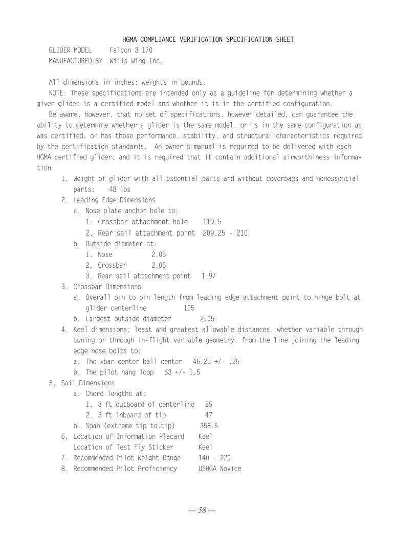
— 58 —
HGMA COMPLIANCE VERIFICATION SPECIFICATION SHEETGLIDER MODEL Falcon 3 170 MANUFACTURED BY Wills Wing Inc.
All dimensions in inches; weights in pounds.NOTE: These specifications are intended only as a guideline for determining whether a
given glider is a certified model and whether it is in the certified configuration.Be aware, however, that no set of specifications, however detailed, can guarantee the
ability to determine whether a glider is the same model, or is in the same configuration as was certified, or has those performance, stability, and structural characteristics required by the certification standards. An owner’s manual is required to be delivered with each HGMA certified glider, and it is required that it contain additional airworthiness informa-tion.
1. Weight of glider with all essential parts and without coverbags and nonessential parts: 48 lbs
2. Leading Edge Dimensionsa. Nose plate anchor hole to:
1. Crossbar attachment hole 119.5 2. Rear sail attachment point 209.25 - 210
b. Outside diameter at:1. Nose 2.052. Crossbar 2.053. Rear sail attachment point 1.97
3. Crossbar Dimensionsa. Overall pin to pin length from leading edge attachment point to hinge bolt at
glider centerline 105b. Largest outside diameter 2.05
4. Keel dimensions; least and greatest allowable distances, whether variable through tuning or through in-flight variable geometry, from the line joining the leading edge nose bolts to:a. The xbar center ball center 46.25 +/- .25 b. The pilot hang loop 63 +/- 1.5
5. Sail Dimensionsa. Chord lengths at:
1. 3 ft outboard of centerline 85 2. 3 ft inboard of tip 47
b. Span (extreme tip to tip) 358.56. Location of Information Placard Keel Location of Test Fly Sticker Keel 7. Recommended Pilot Weight Range 140 - 220 8. Recommended Pilot Proficiency USHGA Novice
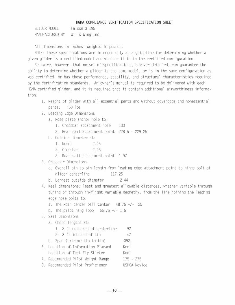
— 59 —
HGMA COMPLIANCE VERIFICATION SPECIFICATION SHEETGLIDER MODEL Falcon 3 195 MANUFACTURED BY Wills Wing Inc. All dimensions in inches; weights in pounds.NOTE: These specifications are intended only as a guideline for determining whether a
given glider is a certified model and whether it is in the certified configuration.Be aware, however, that no set of specifications, however detailed, can guarantee the
ability to determine whether a glider is the same model, or is in the same configuration as was certified, or has those performance, stability, and structural characteristics required by the certification standards. An owner’s manual is required to be delivered with each HGMA certified glider, and it is required that it contain additional airworthiness informa-tion.
1. Weight of glider with all essential parts and without coverbags and nonessential parts: 53 lbs
2. Leading Edge Dimensionsa. Nose plate anchor hole to:
1. Crossbar attachment hole 133 2. Rear sail attachment point 228.5 - 229.25
b. Outside diameter at:1. Nose 2.052. Crossbar 2.053. Rear sail attachment point 1.97
3. Crossbar Dimensionsa. Overall pin to pin length from leading edge attachment point to hinge bolt at
glider centerline 117.25b. Largest outside diameter 2.44
4. Keel dimensions; least and greatest allowable distances, whether variable through tuning or through in-flight variable geometry, from the line joining the leading edge nose bolts to:a. The xbar center ball center 48.75 +/- .25 b. The pilot hang loop 66.75 +/- 1.5
5. Sail Dimensionsa. Chord lengths at:
1. 3 ft outboard of centerline 922. 3 ft inboard of tip 47
b. Span (extreme tip to tip) 3926. Location of Information Placard Keel Location of Test Fly Sticker Keel 7. Recommended Pilot Weight Range 175 - 275 8. Recommended Pilot Proficiency USHGA Novice
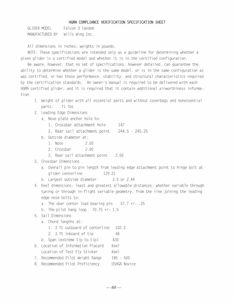
— 60 —
HGMA COMPLIANCE VERIFICATION SPECIFICATION SHEETGLIDER MODEL Falcon 3 Tandem MANUFACTURED BY Wills Wing Inc.
All dimensions in inches; weights in pounds.NOTE: These specifications are intended only as a guideline for determining whether a
given glider is a certified model and whether it is in the certified configuration.Be aware, however, that no set of specifications, however detailed, can guarantee the
ability to determine whether a glider is the same model, or is in the same configuration as was certified, or has those performance, stability, and structural characteristics required by the certification standards. An owner’s manual is required to be delivered with each HGMA certified glider, and it is required that it contain additional airworthiness informa-tion.
1. Weight of glider with all essential parts and without coverbags and nonessential parts: 71 lbs
2. Leading Edge Dimensionsa. Nose plate anchor hole to:
1. Crossbar attachment hole 147 2. Rear sail attachment point 244.5 - 245.25
b. Outside diameter at:1. Nose 2.002. Crossbar 2.003. Rear sail attachment point 2.00
3. Crossbar Dimensionsa. Overall pin to pin length from leading edge attachment point to hinge bolt at
glider centerline 129.21b. Largest outside diameter 2.5 or 2.44
4. Keel dimensions; least and greatest allowable distances, whether variable through tuning or through in-flight variable geometry, from the line joining the leading edge nose bolts to:a. The xbar center load bearing pin 57.7 +/- .25 b. The pilot hang loop 70.75 +/- 1.5
5. Sail Dimensionsa. Chord lengths at:
1. 3 ft outboard of centerline 102.3 2. 3 ft inboard of tip 48
b. Span (extreme tip to tip) 4306. Location of Information Placard Keel Location of Test Fly Sticker Keel 7. Recommended Pilot Weight Range 185 - 5008. Recommended Pilot Proficiency USHGA Novice
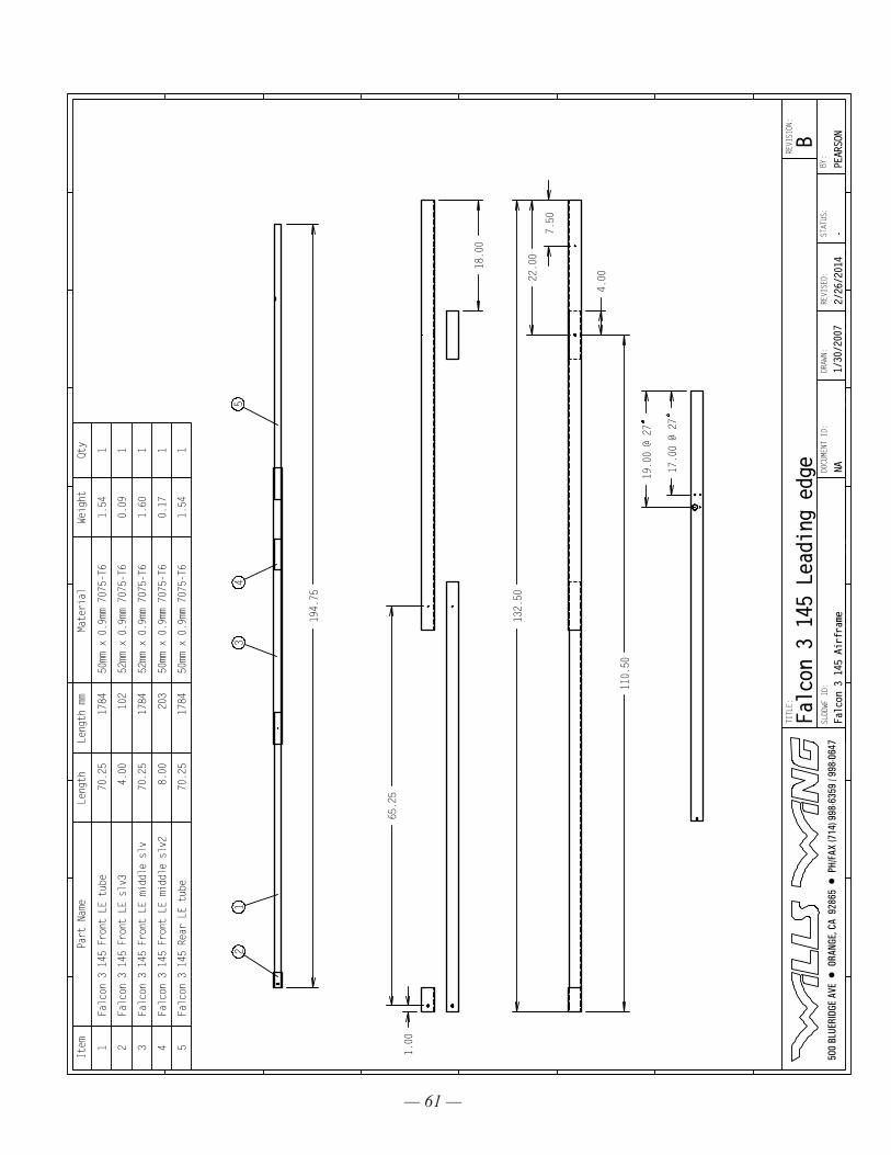
— 61 —
194.75
21
34
5
65.25
1.00
18.00
7.50
22.00
132.50
4.00
110.50
19.00 @ 27
17.00 @ 27
Item
Part Name
Length
Length mm
Material
Weight
Qty
1Falcon 3 145 Front LE tube
70.25
1784
50mm x 0.9mm 7075-T6
1.54
1
2Falcon 3 145 Front LE slv3
4.00
102
52mm x 0.9mm 7075-T6
0.09
1
3Falcon 3 145 Front LE middle slv
70.25
1784
52mm x 0.9mm 7075-T6
1.60
1
4Falcon 3 145 Front LE middle slv2
8.00
203
50mm x 0.9mm 7075-T6
0.17
1
5Falcon 3 145 Rear LE tube
70.25
1784
50mm x 0.9mm 7075-T6
1.54
1
500
BLU
ERID
GE A
VE •
ORA
NGE,
CA
928
65 •
PH/
FAX
(714
) 998
-635
9 / 9
98-0
647
TITLE:
SLDDWF ID:
DRAWN:
Falcon 3 145 Airframe
2/26
/201
4STATUS:
-BY
:REVISED:
NADOCU
MENT
ID:
1/30
/200
7
REVISION:
PEARSONB
Falcon 3 145 Leading edge
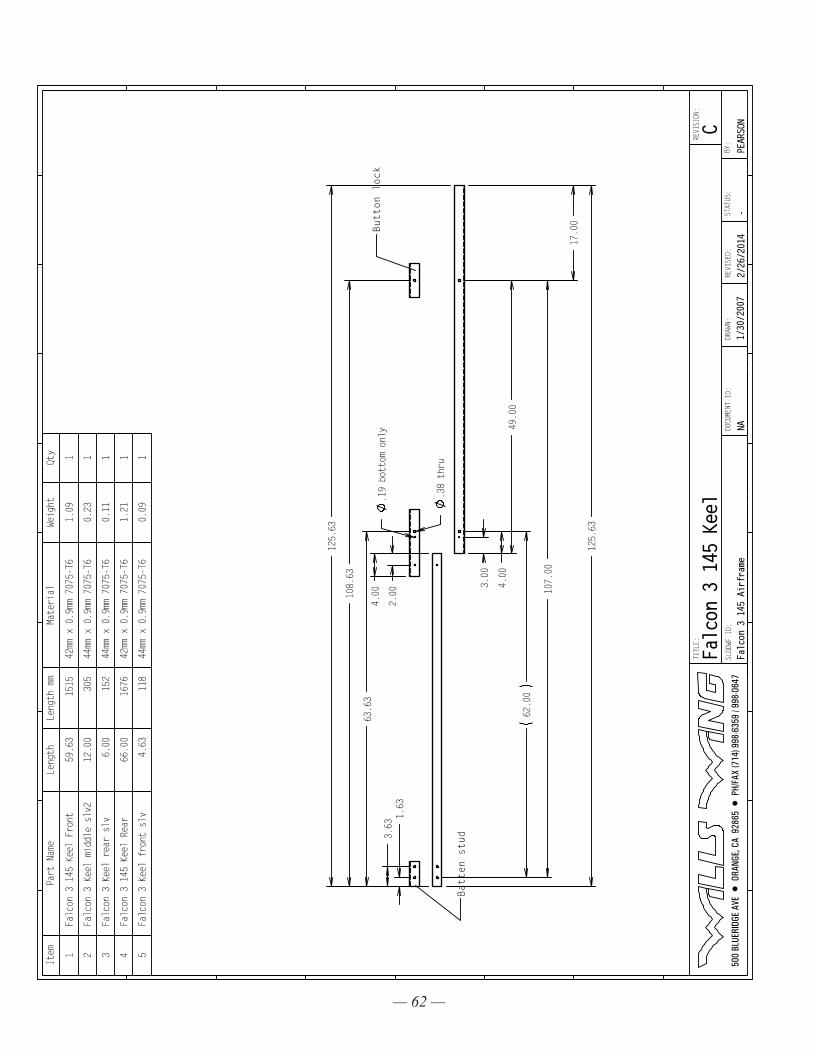
— 62 —
49.00
.38 thru
.19 bottom only
62.00
1.63
3.63
2.00
4.00
4.00
3.00
107.00
125.63
17.00
63.63
108.63
125.63
Batten stud
Button lock
Item
Part Name
Length
Length mm
Material
Weight
Qty
1Falcon 3 145 Keel Front
59.63
1515
42mm x 0.9mm 7075-T6
1.09
1
2Falcon 3 Keel middle slv2
12.00
305
44mm x 0.9mm 7075-T6
0.23
1
3Falcon 3 Keel rear slv
6.00
152
44mm x 0.9mm 7075-T6
0.11
1
4Falcon 3 145 Keel Rear
66.00
1676
42mm x 0.9mm 7075-T6
1.21
1
5Falcon 3 Keel front slv
4.63
118
44mm x 0.9mm 7075-T6
0.09
1
500
BLU
ERID
GE A
VE •
ORA
NGE,
CA
928
65 •
PH/
FAX
(714
) 998
-635
9 / 9
98-0
647
TITLE:
SLDDWF ID:
DRAWN:
Falcon 3 145 Airframe
2/26
/201
4STATUS:
-BY
:REVISED:
NADOCU
MENT
ID:
1/30
/200
7
REVISION:
PEARSONC
Falcon 3 145 Keel
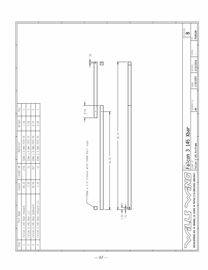
— 63 —
64.25
.63
8.00
50mm x 2.0 sleeve with 50mm ball cups
.75
1.50
96.75
Item
Part Name
Length
Length mm
Material
Weight
Qty
1Falcon 3 145 Xbar Inboard
68.25
1734
52mm x 0.9mm 7075-T6
1.54
1
2Falcon 3 145 Xbar slv
2.00
5152mm x 0.9mm 7075-T6
0.04
1
3Falcon 3 145 Xbar Outboard
36.50
927
50mm x 0.9mm 7075-T6
0.79
1
4Falcon 3 145 Xbar Inboard slv
2.00
5152mm x 0.9mm 7075-T6
0.04
1
500
BLU
ERID
GE A
VE •
ORA
NGE,
CA
928
65 •
PH/
FAX
(714
) 998
-635
9 / 9
98-0
647
TITLE:
SLDDWF ID:
DRAWN:
Falcon 3 145 Airframe
2/16/2014
STATUS:
-BY
:REVISED:
NADOCU
MENT
ID:
1/30
/200
7
REVISION:
PEARSONB
Falcon 3 145 Xbar
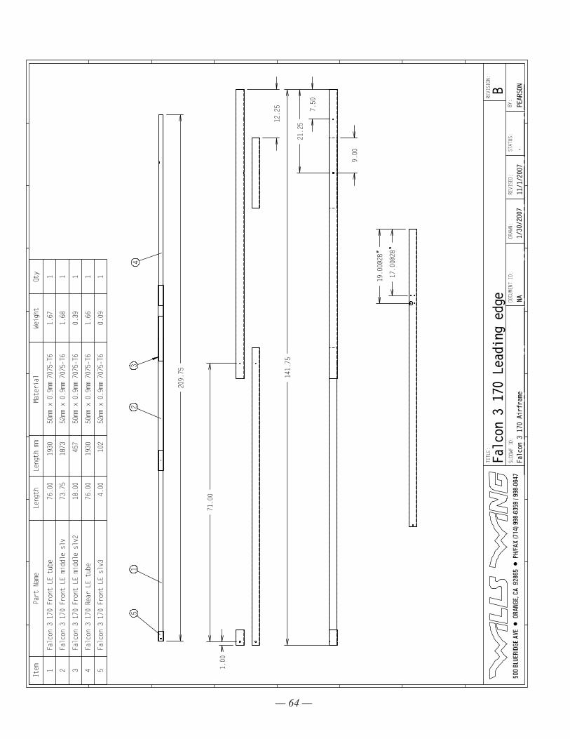
— 64 —
209.75
51
23
4
1.00
71.00
12.25 7.50
21.25
141.75
9.00
19.00@28
17.00@28
Item
Part Name
Length
Length mm
Material
Weight
Qty
1Falcon 3 170 Front LE tube
76.00
1930
50mm x 0.9mm 7075-T6
1.67
1
2Falcon 3 170 Front LE middle slv
73.75
1873
52mm x 0.9mm 7075-T6
1.68
1
3Falcon 3 170 Front LE middle slv2
18.00
457
50mm x 0.9mm 7075-T6
0.39
1
4Falcon 3 170 Rear LE tube
76.00
1930
50mm x 0.9mm 7075-T6
1.66
1
5Falcon 3 170 Front LE slv3
4.00
102
52mm x 0.9mm 7075-T6
0.09
1
500
BLU
ERID
GE A
VE •
ORA
NGE,
CA
928
65 •
PH/
FAX
(714
) 998
-635
9 / 9
98-0
647
TITLE:
SLDDWF ID:
DRAWN:
Falc
on 3
170
Air
fram
e11/1/2007
STATUS:
-BY
:REVISED:
NADOCU
MENT
ID:
1/30/2007
REVISION:
PEAR
SONB
Falcon 3 170 Leading edge
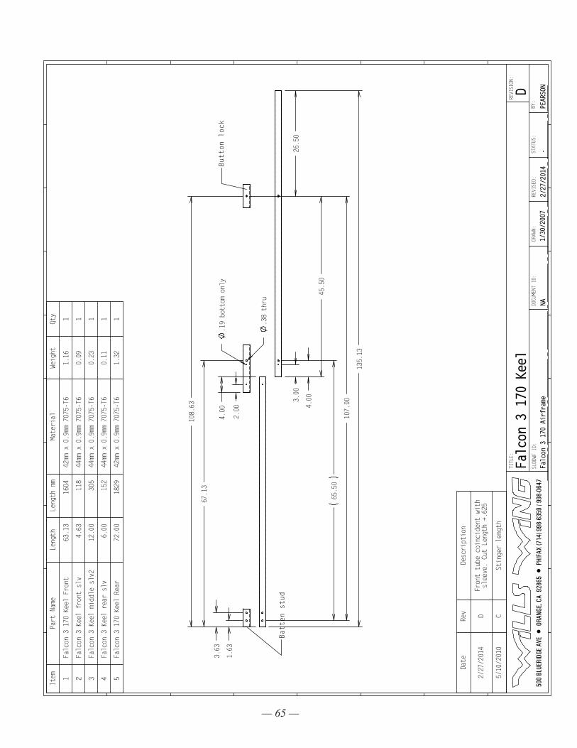
— 65 —
4.00
3.00
4.00
45.50
107.00
.38 thru
.19 bottom only
2.00
65.50
1.63
3.63
135.13
26.50
67.13
108.63
Batten stud
Button lock
Item
Part Name
Length
Length mm
Material
Weight
Qty
1Falcon 3 170 Keel Front
63.13
1604
42mm x 0.9mm 7075-T6
1.16
1
2Falcon 3 Keel front slv
4.63
118
44mm x 0.9mm 7075-T6
0.09
1
3Falcon 3 Keel middle slv2
12.00
305
44mm x 0.9mm 7075-T6
0.23
1
4Falcon 3 Keel rear slv
6.00
152
44mm x 0.9mm 7075-T6
0.11
1
5Falcon 3 170 Keel Rear
72.00
1829
42mm x 0.9mm 7075-T6
1.32
1
Date
Rev
Description
2/27/2014
DFront tube coincident with
sleeve. Cut Length +.625
5/10/2010
CStinger length
500
BLU
ERID
GE A
VE •
ORA
NGE,
CA
928
65 •
PH/
FAX
(714
) 998
-635
9 / 9
98-0
647
TITLE:
SLDDWF ID:
DRAWN:
Falc
on 3
170
Air
fram
e2/
27/2
014
STATUS:
-BY
:REVISED:
NADOCU
MENT
ID:
1/30/2007
REVISION:
PEAR
SOND
Falc
on 3
170
Kee
l
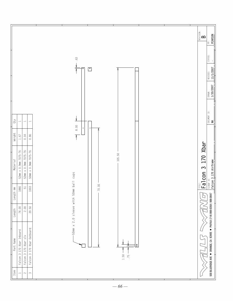
— 66 —
70.00
.63
8.00
50mm x 2.0 sleeve with 50mm ball cups
.75
1.50
105.50
Item
Part Name
Length
Length mm
Material
Weight
Qty
1Falcon 3 170 Xbar Inboard
74.00
1880
52mm x 0.9mm 7075-T6
1.67
1
2Falcon 3 170 Xbar slv
2.00
5152mm x 0.9mm 7075-T6
0.04
1
3Falcon 3 170 Xbar Outboard
39.50
1003
50mm x 0.9mm 7075-T6
0.86
1
500
BLU
ERID
GE A
VE •
ORA
NGE,
CA
928
65 •
PH/
FAX
(714
) 998
-635
9 / 9
98-0
647
TITLE:
SLDDWF ID:
DRAWN:
Falc
on 3
170
Air
fram
e11/1/2007
STATUS:
-BY
:REVISED:
NADOCU
MENT
ID:
1/30/2007
REVISION:
PEAR
SONB
Falcon 3 170 Xbar
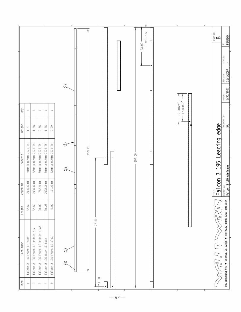
— 67 —
229.
25
51
23
4
1.00
77.5
0
4/27/06 change pin orientation to vertical
7.50
23.0
0
157.
00
19.0
0@27
17.0
0@27
Item
Part
Nam
eLe
ngth
Leng
th m
mMa
teri
alWe
ight
Qty
1Fa
lcon
3 1
95 F
ront
LE
tube
82.5
020
95.5
mm
50mm
x 0
.9mm
707
5-T6
1.81
1
2Fa
lcon
3 1
95 F
ront
LE
midd
le s
lv82
.50
2095
.5 m
m52
mm x
0.9
mm 7
075-
T61.
881
3Fa
lcon
3 1
95 F
ront
LE
midd
le s
lv2
30.0
076
2.0
mm50
mm x
0.9
mm 7
075-
T60.
661
4Fa
lcon
3 1
95 R
ear
LE t
ube
80.2
520
38.3
mm
50mm
x 0
.9mm
707
5-T6
1.76
1
5Fa
lcon
3 1
95 F
ront
LE
slv3
4.00
101.
6 mm
52mm
x 0
.9mm
707
5-T6
0.09
1
500
BLU
ERID
GE A
VE •
ORA
NGE,
CA
928
65 •
PH/
FAX
(714
) 998
-635
9 / 9
98-0
647
TITL
E:
SLDD
WF I
D:DRAWN:
Falc
on 3
195
Air
fram
e11/1/2007
STATUS:
-BY:
REVI
SED:
NADOCUMENT ID:
1/30/2007
REVI
SION
:
PEARSONB
Falc
on 3
195
Lea
ding
edg
e
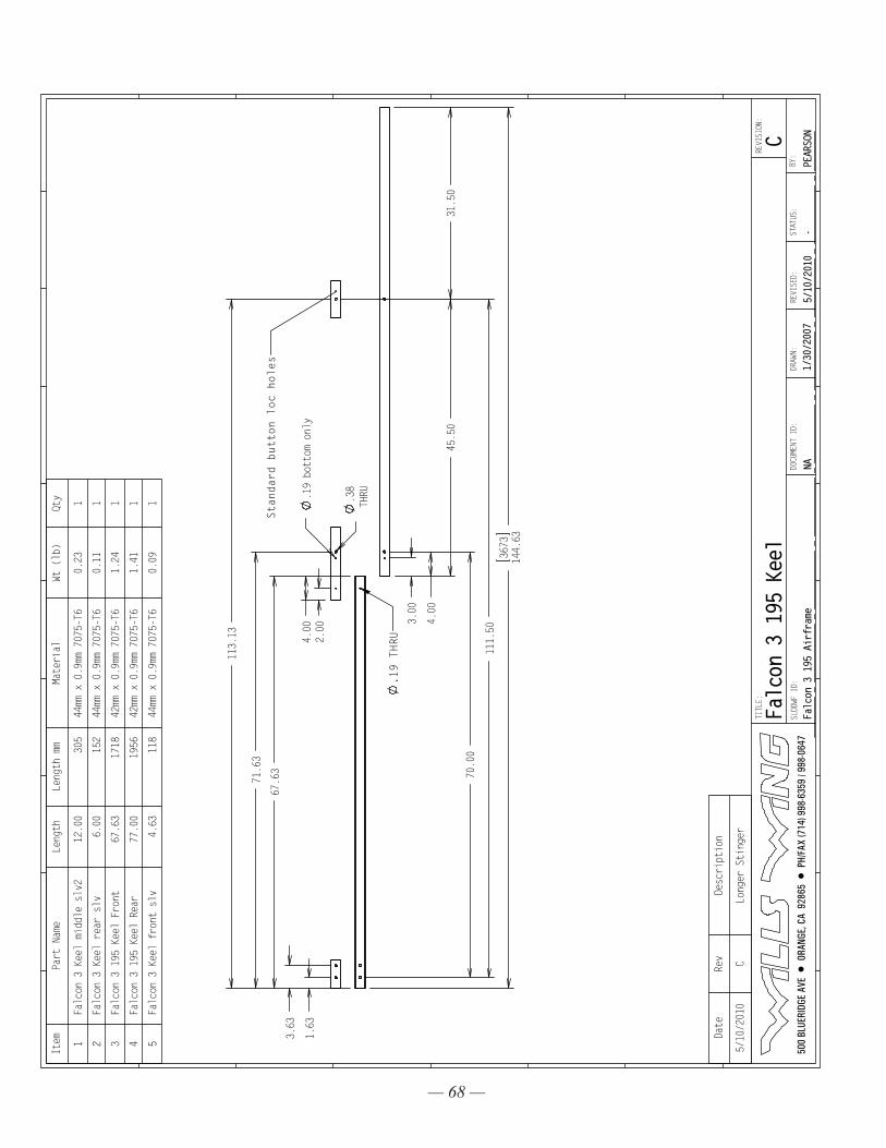
— 68 —
4.00
3.00
4.00
45.50
111.50
.38
THRU.19 bottom only
2.00
1.63
3.63
70.00
3673
144.63
31.50
67.63
71.63
113.13
6/1/2006
both 170 and 195 mosquito compatible if
keel trimmed at edge of rear sleeve. No easy
way to install stinger except splice fwd of
rear junction
4/24/2006 Notes
+ Mosquito 47 from hang not possible)
+ P2 requires rear wires to fit 2in shorter
nose to rear keel
Standard button loc holes
.19 THRU
Item
Part Name
Length
Length mm
Material
Wt (lb)
Qty
1Falcon 3 Keel middle slv2
12.00
305
44mm x 0.9mm 7075-T6
0.23
1
2Falcon 3 Keel rear slv
6.00
152
44mm x 0.9mm 7075-T6
0.11
1
3Falcon 3 195 Keel Front
67.63
1718
42mm x 0.9mm 7075-T6
1.24
1
4Falcon 3 195 Keel Rear
77.00
1956
42mm x 0.9mm 7075-T6
1.41
1
5Falcon 3 Keel front slv
4.63
118
44mm x 0.9mm 7075-T6
0.09
1
Date
Rev
Description
5/10/2010
CLonger Stinger
500
BLU
ERID
GE A
VE •
ORA
NGE,
CA
928
65 •
PH/
FAX
(714
) 998
-635
9 / 9
98-0
647
TITLE:
SLDDWF ID:
DRAWN:
Falc
on 3
195
Air
fram
e5/10/2010
STATUS:
-BY:
REVI
SED:
NADOCU
MENT
ID:
1/30/2007
REVISION:
PEARSONC
Falc
on 3
195
Kee
l
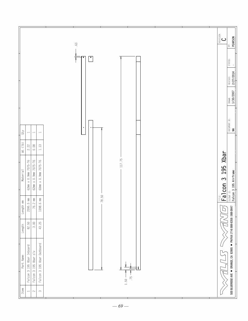
— 69 —
.63
78.50
.75
1.50
117.75
3/24/2006
Added pin hole to extend Xbar .25
equivalent to .5 luff reduction
or 2 in shorter sweep wire.
4/21/2006
52/50 Xbar with 3' overlap weighs same as 62/60 xbar
compare cost and strength
one problem is that the outboard Xbar would have to be
disconnected from the LE for shortpack
4/27/06 change pin orientatin to vertical
Item
Part Name
Length
Length mm
Material
Wt (lb)
Qty
1Falcon 3 195 Xbar Inboard
82.50
2095.5 mm
62mm x 0.9mm 7075-T6
2.22
1
2Falcon 3 195 Xbar slv
3.00
76.2 mm
62mm x 0.9mm 7075-T6
0.08
1
3Falcon 3 195 Xbar Outboard
43.25
1098.6 mm
60mm x 0.9mm 7075-T6
1.13
1
500
BLU
ERID
GE A
VE •
ORA
NGE,
CA
928
65 •
PH/
FAX
(714
) 998
-635
9 / 9
98-0
647
TITLE:
SLDDWF ID:
DRAWN:
Falc
on 3
195
Air
fram
e2/27/2014
STAT
US:
-BY
:REVISED:
NADOCUMENT ID:
1/30/2007
REVI
SION
:
PEARSONC
Falcon 3 195 Xbar
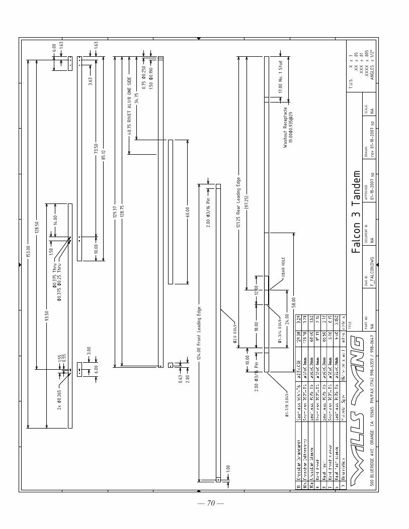
— 70 —
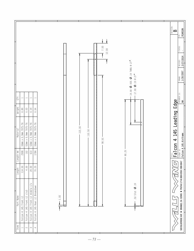
— 71 —
7.50
12.00
115.00
110.50
98.50
1.00
17.00
.19 @ 27
19.00
.935
.19 THRU @ 27
.50 Slot
.19
80.25
Item
Part Name
Length
Length mm
Material
Weight
QTY.
1Falcon 4 145 Front LE
114.50
2908
50mm x 0.9mm 7075-T6
0.89
1
2Falcon 4 145 Front LE slv3
4.00
102
52mm x 0.9mm 7075-T6
0.03
1
3Falcon 4 145 Front LE middle slv
24.00
610
52mm x 0.9mm 7075-T6
0.19
1
4Falcon 4 145 Rear LE Breakdown
70.25
1784
50mm x 0.9mm 7075-T6
0.54
1
500
BLU
ERID
GE A
VE •
ORA
NGE,
CA
928
65 •
PH/
FAX
(714
) 998
-635
9 / 9
98-0
647
TITLE:
SLDDWF ID:
DRAWN:
Falc
on 4
145
Air
fram
e2/
27/2
014
STATUS:
-BY
:REVISED:
NADOCU
MENT
ID:
1/30
/200
7
REVISION:
PEARSONB
Falc
on 4
145
Lea
ding
Edg
e
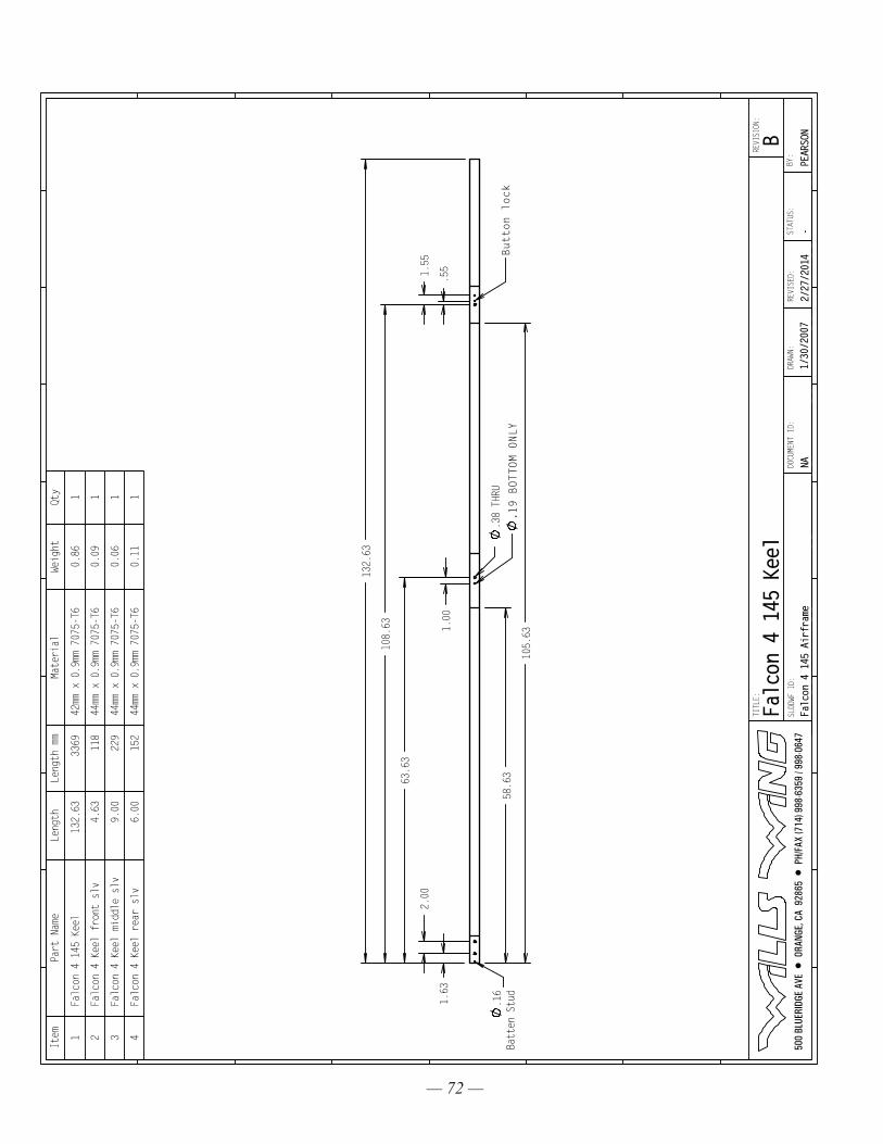
— 72 —
.38 THRU
1.63
108.63
132.63
63.63
2.00
1.00
.55
1.55
58.63
105.63
.16
Batten Stud
Button lock
.19 BOTTOM ONLY
Item
Part Name
Length
Length mm
Material
Weight
Qty
1Falcon 4 145 Keel
132.63
3369
42mm x 0.9mm 7075-T6
0.86
1
2Falcon 4 Keel front slv
4.63
118
44mm x 0.9mm 7075-T6
0.09
1
3Falcon 4 Keel middle slv
9.00
229
44mm x 0.9mm 7075-T6
0.06
1
4Falcon 4 Keel rear slv
6.00
152
44mm x 0.9mm 7075-T6
0.11
1
500
BLU
ERID
GE A
VE •
ORA
NGE,
CA
928
65 •
PH/
FAX
(714
) 998
-635
9 / 9
98-0
647
TITLE:
SLDDWF ID:
DRAWN:
Falc
on 4
145
Air
fram
e2/
27/2
014
STATUS:
-BY
:REVISED:
NADOCU
MENT
ID:
1/30
/200
7
REVISION:
PEARSONB
Falcon 4 145 Keel
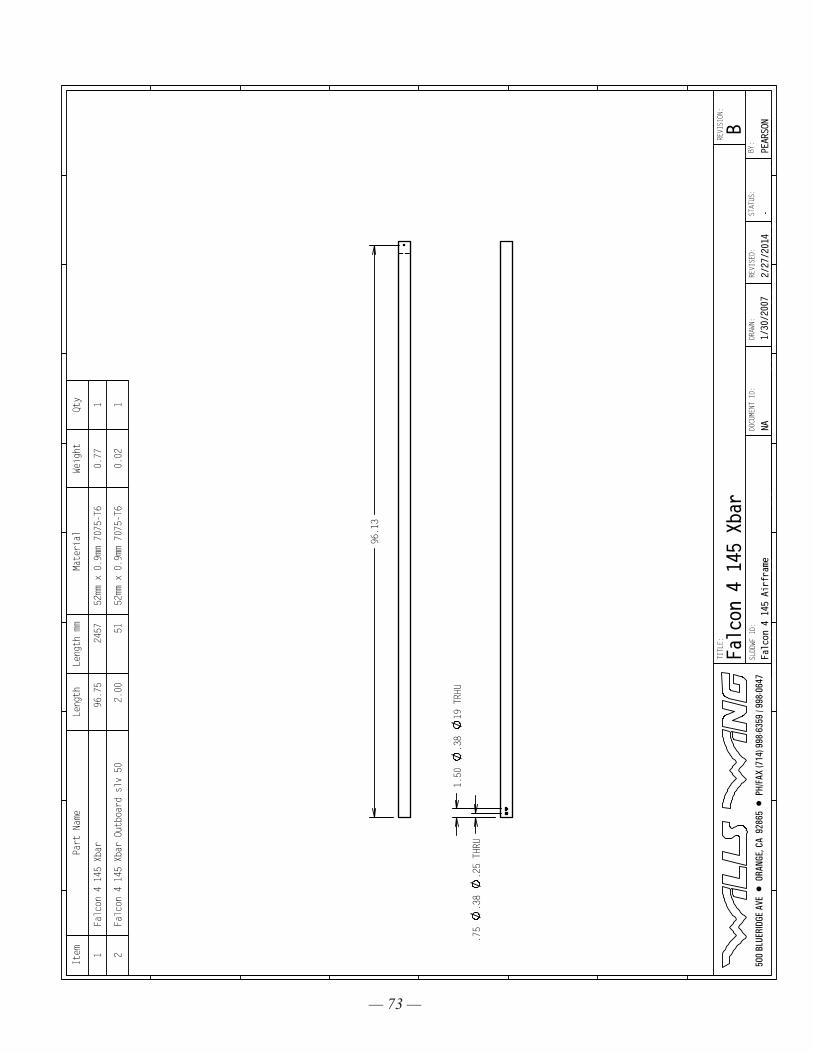
— 73 —
.75
.38
.25 THRU
1.50
.38
19 TRHU
96.13
Item
Part Name
Length
Length mm
Material
Weight
Qty
1Falcon 4 145 Xbar
96.75
2457
52mm x 0.9mm 7075-T6
0.77
1
2Falcon 4 145 Xbar Outboard slv 50
2.00
5152mm x 0.9mm 7075-T6
0.02
1
500
BLU
ERID
GE A
VE •
ORA
NGE,
CA
928
65 •
PH/
FAX
(714
) 998
-635
9 / 9
98-0
647
TITLE:
SLDDWF ID:
DRAWN:
Falc
on 4
145
Air
fram
e2/
27/2
014
STATUS:
-BY
:REVISED:
NADOCU
MENT
ID:
1/30
/200
7
REVISION:
PEARSONB
Falcon 4 145 Xbar
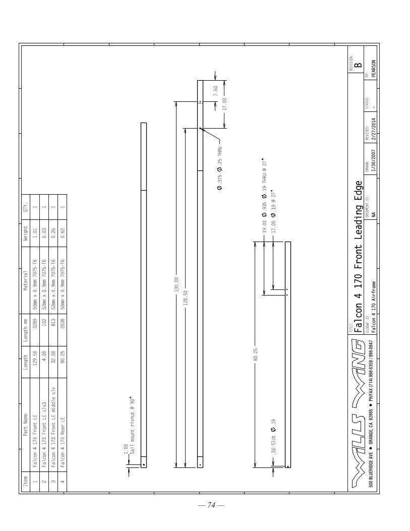
— 74 —
7.50
17.00
130.00
120.50
.375
.25 THRU
1.00
Sail mount rivnut @ 90
17.00
.19 @ 27
19.00
.935
.19 THRU @ 27
.50 Slot
.19
80.25
Item
Part Name
Length
Length mm
Material
Weight
QTY.
1Falcon 4 170 Front LE
129.50
3289
50mm x 0.9mm 7075-T6
1.01
1
2Falcon 4 170 Front LE slv3
4.00
102
52mm x 0.9mm 7075-T6
0.03
1
3Falcon 4 170 Front LE middle slv
32.00
813
52mm x 0.9mm 7075-T6
0.26
1
4Falcon 4 170 Rear LE
80.25
2038
50mm x 0.9mm 7075-T6
0.62
1
500
BLU
ERID
GE A
VE •
ORA
NGE,
CA
928
65 •
PH/
FAX
(714
) 998
-635
9 / 9
98-0
647
TITLE:
SLDDWF ID:
DRAWN:
Falc
on 4
170
Air
fram
e2/
27/2
014
STATUS:
-BY
:REVISED:
NADOCU
MENT
ID:
1/30
/200
7
REVISION:
PEARSONB
Falcon 4 170 Front Leading Edge
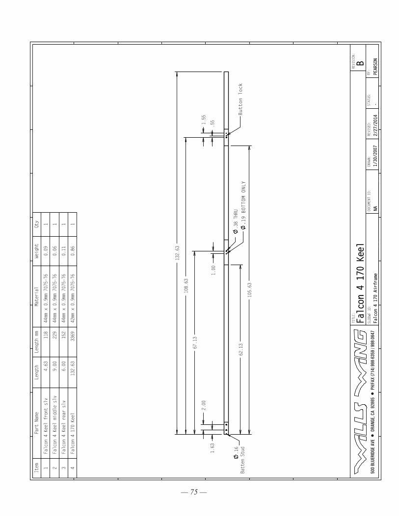
— 75 —
.38 THRU
1.63
108.63
132.63
67.13
2.00
1.00
.55
1.55
62.13
105.63
.16
Batten Stud
Button lock
.19 BOTTOM ONLY
Item
Part Name
Length
Length mm
Material
Weight
Qty
1Falcon 4 Keel front slv
4.63
118
44mm x 0.9mm 7075-T6
0.09
1
2Falcon 4 Keel middle slv
9.00
229
44mm x 0.9mm 7075-T6
0.06
1
3Falcon 4 Keel rear slv
6.00
152
44mm x 0.9mm 7075-T6
0.11
1
4Falcon 4 170 Keel
132.63
3369
42mm x 0.9mm 7075-T6
0.86
1
500
BLU
ERID
GE A
VE •
ORA
NGE,
CA
928
65 •
PH/
FAX
(714
) 998
-635
9 / 9
98-0
647
TITLE:
SLDDWF ID:
DRAWN:
Falc
on 4
170
Air
fram
e2/
27/2
014
STATUS:
-BY
:REVISED:
NADOCU
MENT
ID:
1/30
/200
7
REVISION:
PEARSONB
Falcon 4 170 Keel
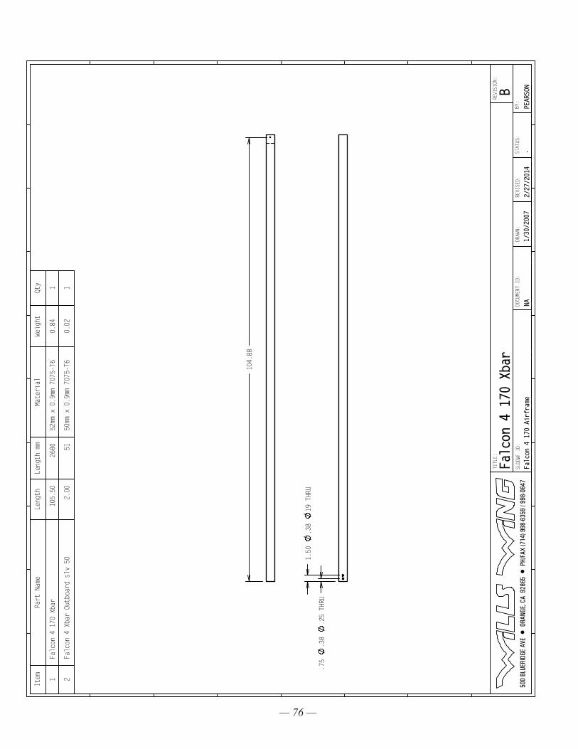
— 76 —
.75
.38
.25 THRU
1.50
.38
19 THRU
104.88
Item
Part Name
Length
Length mm
Material
Weight
Qty
1Falcon 4 170 Xbar
105.50
2680
52mm x 0.9mm 7075-T6
0.84
1
2Falcon 4 Xbar Outboard slv 50
2.00
5150mm x 0.9mm 7075-T6
0.02
1
500
BLU
ERID
GE A
VE •
ORA
NGE,
CA
928
65 •
PH/
FAX
(714
) 998
-635
9 / 9
98-0
647
TITLE:
SLDDWF ID:
DRAWN:
Falc
on 4
170
Air
fram
e2/
27/2
014
STATUS:
-BY
:REVISED:
NADOCU
MENT
ID:
1/30
/200
7
REVISION:
PEARSONB
Falcon 4 170 Xbar
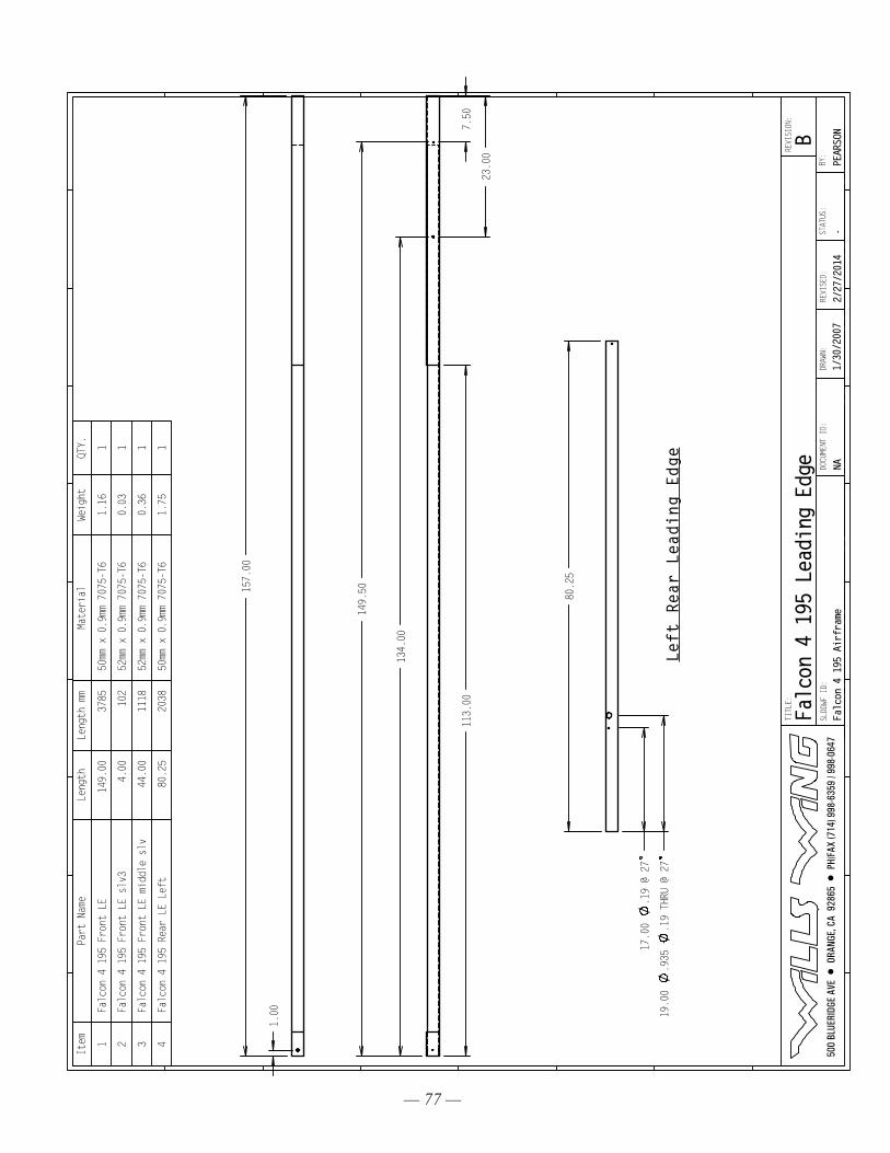
— 77 —
7.50
23.00
149.50
134.00
113.00
1.00
157.00
17.00
.19 @ 27
19.00
.935
.19 THRU @ 27
80.25
Left Rear Leading Edge
Item
Part Name
Length
Length mm
Material
Weight
QTY.
1Falcon 4 195 Front LE
149.00
3785
50mm x 0.9mm 7075-T6
1.16
1
2Falcon 4 195 Front LE slv3
4.00
102
52mm x 0.9mm 7075-T6
0.03
1
3Falcon 4 195 Front LE middle slv
44.00
1118
52mm x 0.9mm 7075-T6
0.36
1
4Falcon 4 195 Rear LE Left
80.25
2038
50mm x 0.9mm 7075-T6
1.75
1
500
BLU
ERID
GE A
VE •
ORA
NGE,
CA
928
65 •
PH/
FAX
(714
) 998
-635
9 / 9
98-0
647
TITLE:
SLDDWF ID:
DRAWN:
Falcon 4 195 Airframe
2/27
/201
4STATUS:
-BY
:REVISED:
NADOCU
MENT
ID:
1/30
/200
7
REVISION:
PEARSONB
Falcon 4 195 Leading Edge
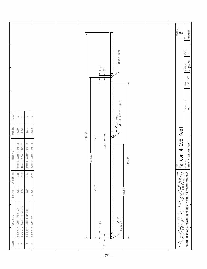
— 78 —
.38 THRU
1.63
113.13
144.63
71.63
2.00
1.00
.55
1.55
66.63
110.13
.16
Batten Stud
Button lock
.19 BOTTOM ONLY
Item
Part Name
Length
Length mm
Material
Weight
Qty
1Falcon 4 Keel front slv
4.63
118
44mm x 0.9mm 7075-T6
0.09
1
2Falcon 4 Keel middle slv
9.00
229
44mm x 0.9mm 7075-T6
0.06
1
3Falcon 4 Keel rear slv
6.00
152
44mm x 0.9mm 7075-T6
0.11
1
4Falcon 4 195 Keel
144.63
3674
42mm x 0.9mm 7075-T6
0.94
1
500
BLU
ERID
GE A
VE •
ORA
NGE,
CA
928
65 •
PH/
FAX
(714
) 998
-635
9 / 9
98-0
647
TITLE:
SLDDWF ID:
DRAWN:
Falcon 4 195 Airframe
2/27
/201
4STATUS:
-BY
:REVISED:
NADOCU
MENT
ID:
1/30
/200
7
REVISION:
PEARSONB
Falc
on 4
195
Kee
l
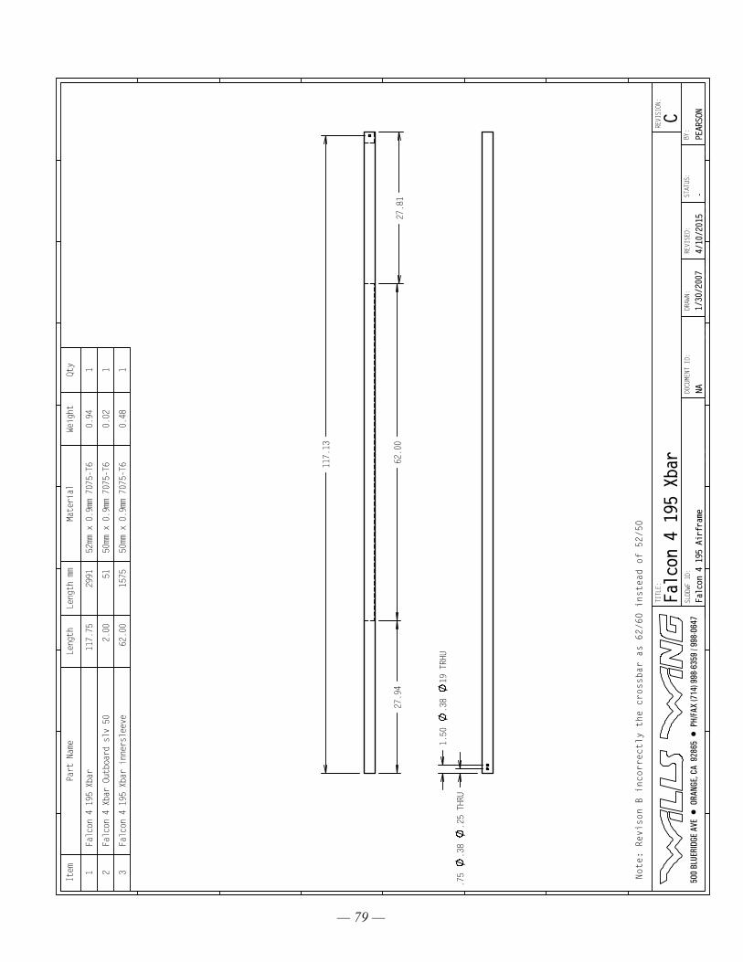
— 79 —
.75
.38
.25 THRU
1.50
.38
19 TRHU
117.13
27.94
27.81
62.00
Note: Revison B incorrectly the crossbar as 62/60 instead of 52/50
Item
Part Name
Length
Length mm
Material
Weight
Qty
1Falcon 4 195 Xbar
117.75
2991
52mm x 0.9mm 7075-T6
0.94
1
2Falcon 4 Xbar Outboard slv 50
2.00
5150mm x 0.9mm 7075-T6
0.02
1
3Falcon 4 195 Xbar innersleeve
62.00
1575
50mm x 0.9mm 7075-T6
0.48
1
500
BLU
ERID
GE A
VE •
ORA
NGE,
CA
928
65 •
PH/
FAX
(714
) 998
-635
9 / 9
98-0
647
TITLE:
SLDDWF ID:
DRAWN:
Falcon 4 195 Airframe
4/10/2015
STATUS:
-BY
:REVISED:
NADOCU
MENT
ID:
1/30
/200
7
REVISION:
PEARSONC
Falc
on 4
195
Xba
r
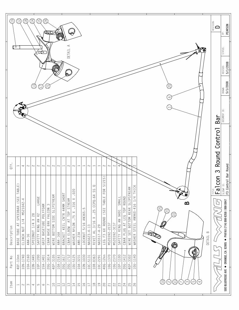
B
A
16
20
DETA
IL B
25
23
22
10 72 11 3 5 4
DETA
IL A
15141812
13 1724
21
19Item
Part No
Desc
ript
ion
QTY.
140F-13nn
BASE TUBE AT SPEEDBAR (SEE TABLE)
1
210N-1740
CLINCH NUT 1/4 MS21042-4
4
310A-2160
AN4-16
2
410N-1445
SPEEDNUT 1/4 X 28
2
510P-1200
SAFETY RING AN R2 LARGE
2
615A-1401
GRIP BASETUBE POLYFOAM
2
720G-1814
CBAR BASE BRK FALCON 3
2
10
40P-3105
WIRE BOTTOM SIDE SLIPSTREAM
2
11
10A-2161
AN4-16A
2
12
20G-1617
BRACKET KEEL CNTR 44MM SHORT
1
13
20G-1712
CBAR ELBOW AT TOP STREAM
2
14
10U-5125
WASHER NYLON .75 X .316 X .020
2
15
10A-3231
AN5-23A
1
16
10N-1030
LOCKNUT 5/16 AN365-5
1
17
10C-5131
NAS623-4-13
2
18
10R-0363
RIVET AL 3/16 X .25 CCPQ-64 SS Q
1
19
10C-2291
NAS517-4-29
1
20
40G-12nn
LEG F3 6X ROUND (SEE TABLE FOR SIZES)
2
21
10G-1370
MS20392-2C37
2
22
10G-2370
MS20392-3C37
2
23
10P-1100
SAFETY RING AN 9491 SMALL
4
24
20G-1412
CBAR PLUG AT LEG TOP ROUND
2
25
40P-3302
WIRE SET BOTTOM REAR SLIPSTREAM
4
26
10U-1140
WASHER STEEL AN960-416 1/4 THICK
2
500
BLU
ERID
GE A
VE •
ORA
NGE,
CA
928
65 •
PH/
FAX
(714
) 998
-635
9 / 9
98-0
647
TITLE:
SLDDWF ID:
DRAW
N:
F3 Control Bar Round
5/1/
2008
STATUS:
BY:
REVI
SED:
DOCUMENT ID:
5/1/
2008
REVI
SION
:
PEAR
SOND
Falcon 3 Round Control Bar
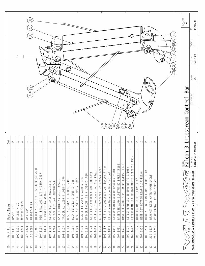
419
1831
5
3020
2420
63
26
2528 211032
IDPart No
Part
Nam
eQnt
310C-4301
NAS6
23-3
-30
2
410
C-52
01NAS623-4-20
2
510G-1290
MS20392-2C29
4
39
10A-3231
AN5-23A
1
37
10C-2291
NAS517-4-29
1
38
10R-0363
RIVET AL 3/16 X .25 CCPQ-64 SS Q
1
610
K-31
33PI
N B
ALL
LOCK
1/4
X 3
3MM
GRIP
2
710N-1030
LOCK
NUT
5/16
AN3
65-5
1
810N-1730
CLIN
CH N
UT 3
/16
MS20
142-
32
910
N-17
40CLINCH NUT 1/4 MS21042-4
2
1010P-1100
SAFETY RING AN 9491 SMALL
4
1110T-1103
SPACER AL .250 X .028 X .770
2
1310
T-41
13BUSH SS .312 X .028 X .240
2
1410T-4114
BUSH
SS
.312
X .
028
X .1
252
1510
T-41
20BUSH SS .3115 X .028 X .850
2
1610T-5103
SPACER NY .560 X .320 X .187
3
1710U-5125
WASH
ER N
YLON
.75
X .
316
X .0
202
1820
G-14
78CB
Plu
g Li
test
ream
Leg
Top
Lef
t1
1920G-1479
CB Plug Litestream Leg Top Right
1
2020
G-14
88CB
Plu
g Li
test
ream
Leg
Bot
tom
Left
1
2120
G-14
89CB
Plu
g Li
test
ream
Leg
Bot
tom
Righ
t1
2420
G-18
43Li
test
ream
Bas
etub
e Br
acke
t Le
ft1
2520G-1844
Lite
stre
am B
aset
ube
Brac
ket
Righ
t1
2640F-1511
BASE
TUBE
ALU
M SL
PSTR
M NO
BRK
TS (
F195
)1
2740
F-15
21BA
SETU
BE A
LUM
SLPS
TRM
NO B
RKTS
(F1
70)
1
2840G-1474
LITESTREAM LEG 65 W/O BRKTS (F195)
2
2940
G-14
77LI
TEST
REAM
LEG
62
W/O
BRKT
S (F
170/
S2 1
35)
2
3040P-3105
WIRE
BOT
TOM
SIDE
SLI
PSTR
EAM
2
3140P-3302
WIRE
SET
BOT
TOM
REAR
SLI
PSTR
EAM
2
3240P-3203
WIRE SET BOTTOM FRONT SLIPSTREAM
2
33
20G-1617
BRACKET KEEL CNTR 44MM SHORT
1
34
20G-1712
CBAR ELBOW AT TOP STREAM
2
500
BLU
ERID
GE A
VE •
ORA
NGE,
CA
928
65 •
PH/
FAX
(714
) 998
-635
9 / 9
98-0
647
TITLE:
SLDDWF ID:
DRAW
N:
Falc
on 3
Lit
estr
eam
5/1/
2008
STATUS:
-BY
:RE
VISE
D:DOCUMENT ID:
NA
REVI
SION
:
PEAR
SONF
Falcon 3 Litestream Control Bar
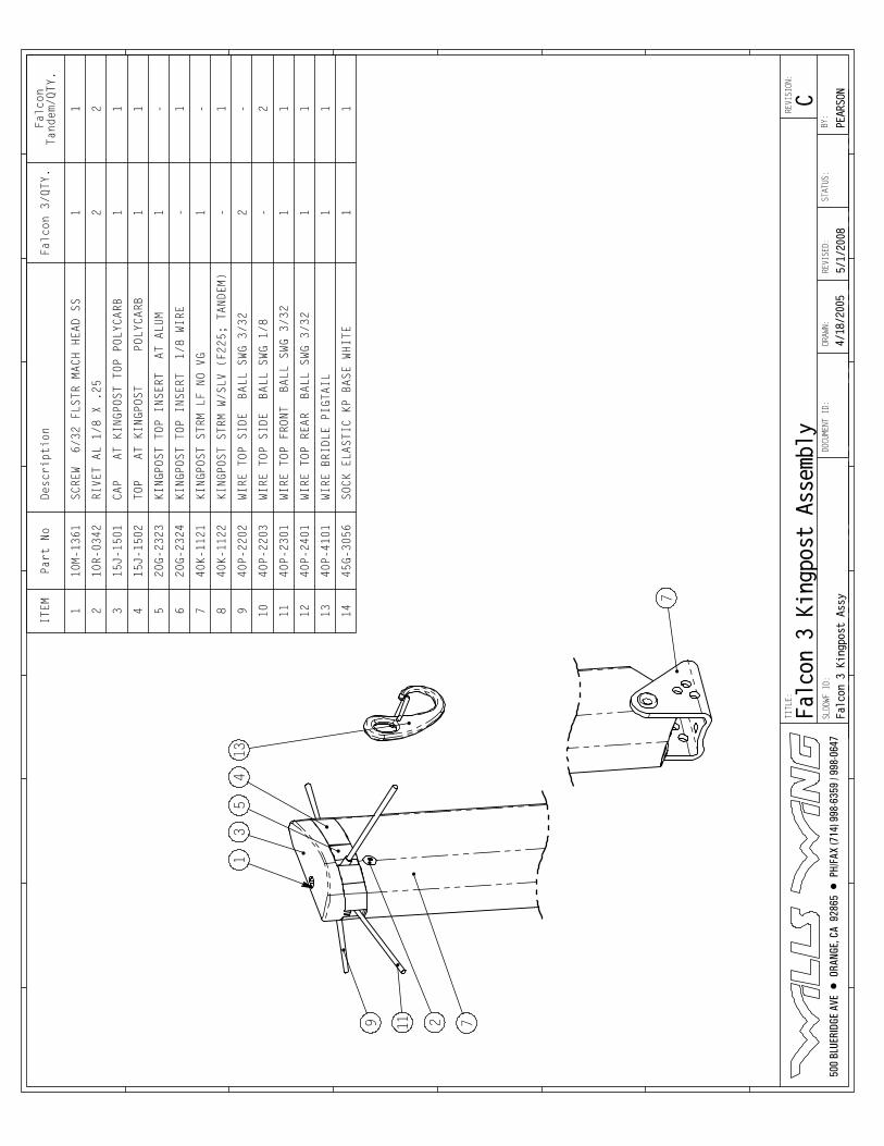
1
2
53
4
7
13
7
119
ITEM
Part No
Desc
ript
ion
Falc
on 3
/QTY
.Falcon
Tandem/QTY.
110M-1361
SCRE
W 6
/32
FLSTR
MACH
HEA
D SS
11
210
R-03
42RI
VET
AL 1
/8 X
.25
22
315J-1501
CAP
AT
KIN
GPOS
T TO
P PO
LYCA
RB1
1
415
J-15
02TO
P
AT K
INGP
OST
POLY
CARB
11
520G-2323
KINGPOST TOP INSER
T A
T AL
UM1
-
620
G-23
24KINGPOST TOP INSERT 1/8 WIRE
-1
740K-1121
KING
POST
STR
M LF
NO
VG1
-
840K-1122
KINGPOST STRM W/SLV (F225; TANDEM)
-1
940P-2202
WIRE
TOP
SID
E B
ALL
SWG
3/32
2-
1040P-2203
WIRE TOP SIDE BALL SWG 1/8
-2
1140
P-23
01WIRE TOP FRONT BALL SWG 3/32
11
1240P-2401
WIRE
TOP
REA
R B
ALL
SWG
3/32
11
1340
P-41
01WIRE BRIDLE PIGTAIL
11
1445
G-30
56SO
CK E
LAST
IC K
P BA
SE W
HITE
11
500
BLU
ERID
GE A
VE •
ORA
NGE,
CA
928
65 •
PH/
FAX
(714
) 998
-635
9 / 9
98-0
647
TITLE:
SLDDWF ID:
DRAW
N:
Falc
on 3
Kin
gpos
t As
sy5/
1/20
08STATUS:
BY:
REVI
SED:
DOCUMENT ID:
4/18
/200
5
REVI
SION
:
PEAR
SONC
Falc
on 3
Kin
gpos
t As
semb
ly
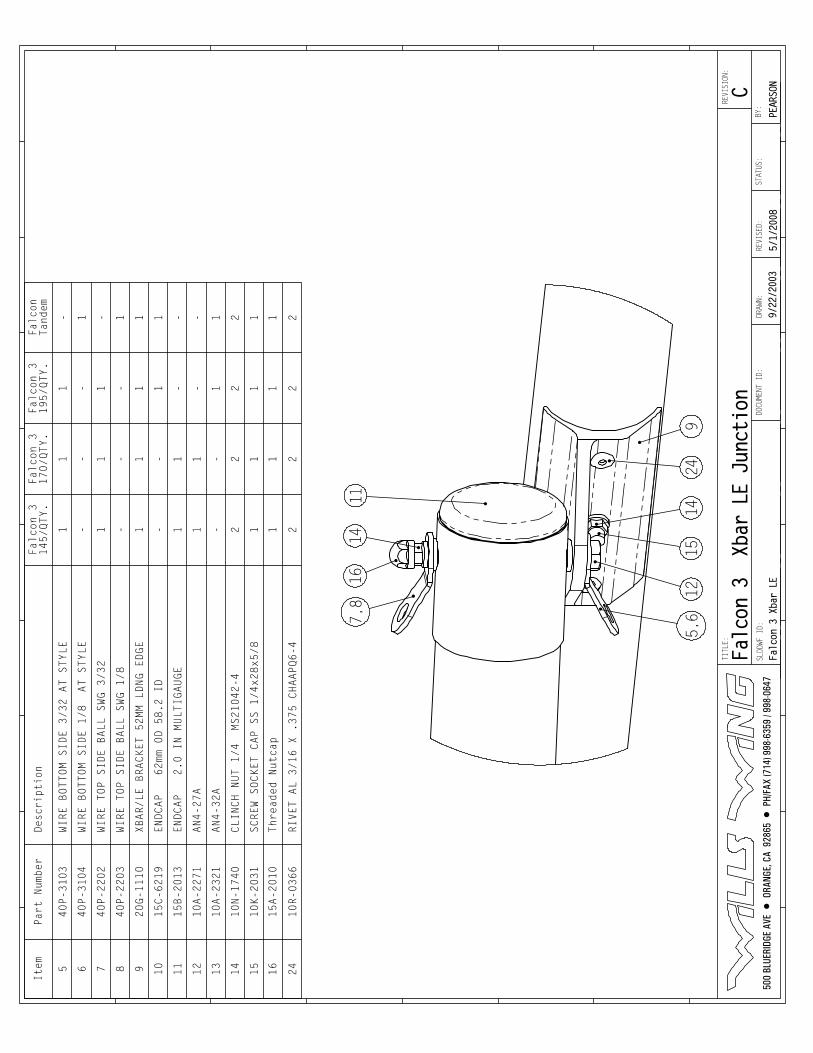
D
7,8
1614
11
924
1415
125,6
Item
Part Number
Desc
ript
ion
Falcon 3
145/QTY.
Falcon 3
170/QTY.
Falcon 3
195/QTY.
Falcon
Tand
em
540P-3103
WIRE BOTTOM SIDE 3/32 AT STYLE
11
1-
640P-3104
WIRE BOTTOM SIDE 1/8 AT STYLE
--
-1
740P-2202
WIRE TOP SIDE BALL SWG 3/32
11
1-
840P-2203
WIRE TOP SIDE BALL SWG 1/8
--
-1
920G-1110
XBAR/LE BRACKET 52MM LDNG EDGE
11
11
10
15C-6219
ENDCAP 62mm OD 58.2 ID
--
11
11
15B-2013
ENDCAP 2.0 IN MULTIGAUGE
11
--
12
10A-2271
AN4-27A
11
--
13
10A-2321
AN4-32A
--
11
14
10N-1740
CLINCH NUT 1/4 MS21042-4
22
22
15
10K-2031
SCREW SOCKET CAP SS 1/4x28x5/8
11
11
16
15A-2010
Threaded Nutcap
11
11
24
10R-0366
RIVET AL 3/16 X .375 CHAAPQ6-4
22
22
500
BLU
ERID
GE A
VE •
ORA
NGE,
CA
928
65 •
PH/
FAX
(714
) 998
-635
9 / 9
98-0
647
TITLE:
SLDDWF ID:
DRAW
N:
Falcon 3 Xbar LE
5/1/
2008
STATUS:
BY:
REVI
SED:
DOCUMENT ID:
9/22
/200
3
REVI
SION
:
PEAR
SONC
Falc
on 3
Xb
ar L
E Ju
ncti
on
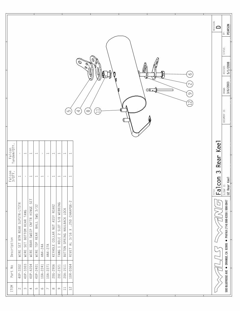
4 85 11
129
62
ITEM
Part No
Desc
ript
ion
Falcon
3/QTY.
Falcon
Tandem/QTY.
240P-3302
WIRE SET BTM REAR SLPSTR-LTSTR
1-
340P-3303
WIRE SET BOTTOM REAR TANG
-1
440P-4204
WIRE XBAR SWEEP CNFTR HINGE SET
11
540P-2401
WIRE TOP REAR BALL SWG 3/32
11
610A-2241
AN4-24A
1-
710A-2271
AN4-27A
-1
820
G-29
06KEYHOLE COLLAR NUT ASSY REAR2
11
920E-2321
TANG 1 HOLE 2 SLOT 5/8 WEBBING
11
1120
A-15
11BUTTON SPRING HAULBACK LOCK
11
12
10R-0364
RIVET AL 3/16 X .250 CHAAPQ6-2
11
500
BLU
ERID
GE A
VE •
ORA
NGE,
CA
928
65 •
PH/
FAX
(714
) 998
-635
9 / 9
98-0
647
TITLE:
SLDDWF ID:
DRAW
N:
U2 R
ear
Keel
5/1/
2008
STATUS:
BY:
REVI
SED:
DOCUMENT ID:
3/6/2003
REVI
SION
:
PEAR
SOND
Falc
on 3
Rea
r Ke
el
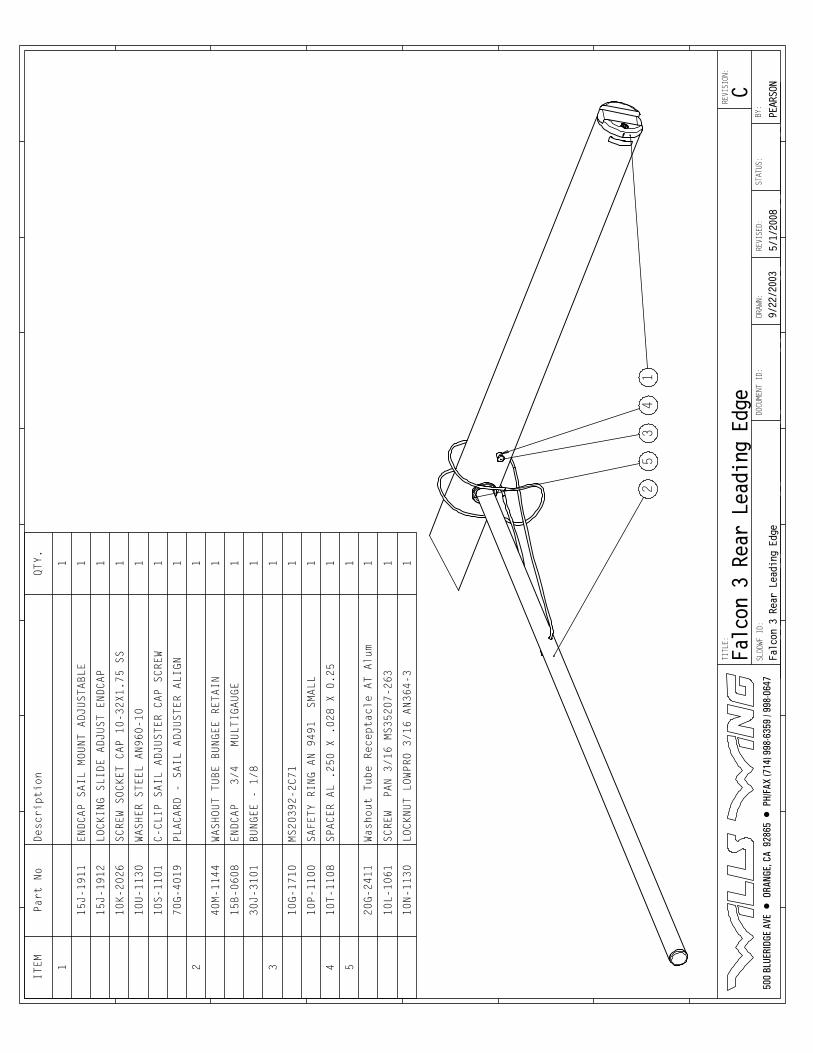
C
53
41
2
ITEM
Part No
Description
QTY.
11
15J-1911
ENDCAP SAIL MOUNT ADJUSTABLE
1
15J-1912
LOCKING SLIDE ADJUST ENDCAP
1
10K-2026
SCREW SOCKET CAP 10-32X1.75 SS
1
10U-1130
WASHER STEEL AN960-10
1
10S-1101
C-CLIP SAIL ADJUSTER CAP SCREW
1
70G-4019
PLACARD - SAIL ADJUSTER ALIGN
1
21
40M-1144
WASHOUT TUBE BUNGEE RETAIN
1
15B-0608
ENDCAP 3/4 MULTIGAUGE
1
30J-3101
BUNGEE - 1/8
1
31
10G-1710
MS20392-2C71
1
10P-1100
SAFETY RING AN 9491 SMALL
1
410T-1108
SPACER AL .250 X .028 X 0.25
1
51
20G-2411
Washout Tube Receptacle AT Alum
1
10L-1061
SCREW PAN 3/16 MS35207-263
1
10N-1130
LOCKNUT LOWPRO 3/16 AN364-3
1
500
BLU
ERID
GE A
VE •
ORA
NGE,
CA
928
65 •
PH/
FAX
(714
) 998
-635
9 / 9
98-0
647
TITLE:
SLDDWF ID:
DRAW
N:
Falcon 3 Rear Leading Edge
5/1/
2008
STATUS:
BY:
REVI
SED:
DOCUMENT ID:
9/22
/200
3
REVI
SION
:
PEAR
SONC
Falc
on 3
Rea
r Le
adin
g Ed
ge
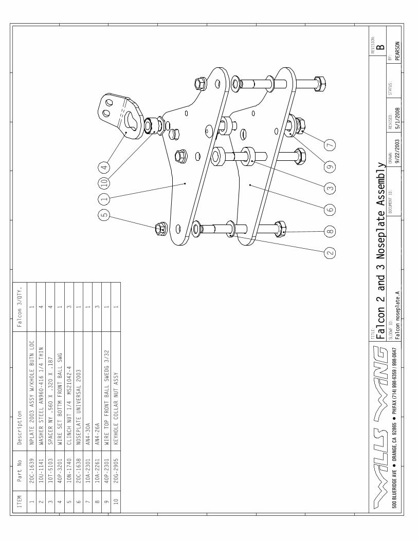
51
104
28
63
97
ITEM
Part No
Desc
ript
ion
Falc
on 3
/QTY
.
120C-1639
NPLATE 2003 ASSY W/KHOLE BUTN LOC
1
210
U-11
41WASHER STEEL AN960-416 1/4 THIN
4
310T-5103
SPACER NY .560 X .320 X .187
4
440
P-32
01WI
RE S
ET B
OTTM
FRO
NT B
ALL
SWG
1
510
N-17
40CLINCH NUT 1/4 MS21042-4
3
620C-1638
NOSEPLATE UNIVERSAL 2003
1
710A-2301
AN4-
30A
1
810A-2261
AN4-26A
3
940
P-23
01WIRE TOP FRONT BALL SWEDG 3/32
1
1020
G-29
05KE
YHOL
E CO
LLAR
NUT
ASS
Y1
500
BLU
ERID
GE A
VE •
ORA
NGE,
CA
928
65 •
PH/
FAX
(714
) 998
-635
9 / 9
98-0
647
TITLE:
SLDDWF ID:
DRAW
N:
Falcon noseplate.A
5/1/
2008
STATUS:
BY:
REVI
SED:
DOCUMENT ID:
9/22
/200
3
REVI
SION
:
PEAR
SONB
Falcon 2 and 3 Noseplate Assembly
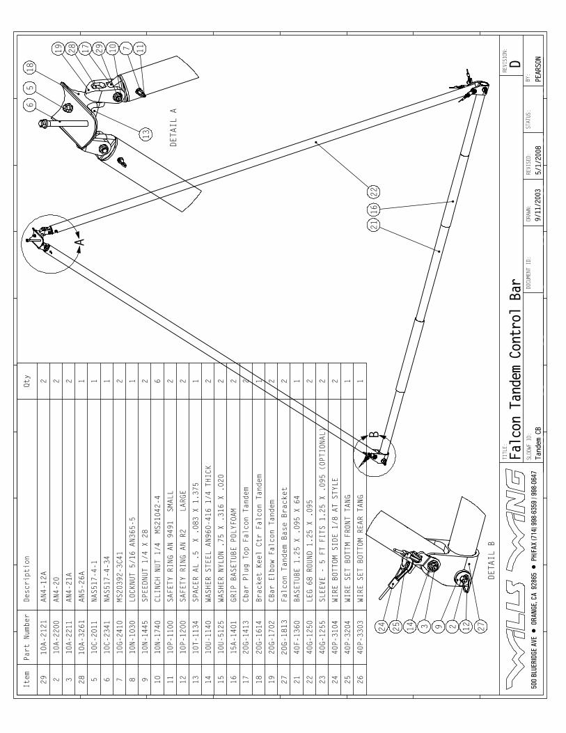
A
B22
1621
DETAIL A 6
518
19 28 17 10 7 1129
13
DETAIL B
24 25 3 9 122 2714
Item
Part Number
Desc
ript
ion
Qty
29
10A-2121
AN4-12A
2
210
A-22
00AN4-20
2
310A-2211
AN4-21A
2
28
10A-3261
AN5-26A
1
510
C-20
11NAS517-4-1
1
610
C-23
41NA
S517
-4-3
41
710
G-24
10MS20392-3C41
2
810N-1030
LOCK
NUT
5/16
AN3
65-5
1
910
N-14
45SP
EEDN
UT 1
/4 X
28
2
1010
N-17
40CLINCH NUT 1/4 MS21042-4
6
1110P-1100
SAFETY RING AN 9491 SMALL
2
1210
P-12
00SAFETY RING AN R2 LARGE
2
1310
T-11
34SP
ACER
AL
.5
X .0
83 X
1.3
751
1410
U-11
40WA
SHER
STE
EL A
N960
-416
1/4
THI
CK2
1510U-5125
WASH
ER N
YLON
.75
X .
316
X .0
202
1615A-1401
GRIP
BAS
ETUB
E PO
LYFO
AM2
1720
G-14
13Cb
ar P
lug
Top
Falc
on T
ande
m2
1820
G-16
14Br
acke
t Ke
el C
tr F
alco
n Ta
ndem
1
1920
G-17
02CB
ar E
lbow
Fal
con
Tand
em2
27
20G-1813
Falcon Tandem Base Bracket
2
2140F-1360
BASE
TUBE
1.2
5 X
.095
X 6
41
2240
G-12
50LE
G 68
ROU
ND 1
.25
X .0
952
2340
G-12
55SL
EEVE
- 5
FT
FITS
1.2
5 X
.095
(OP
TION
AL)
2
2440P-3104
WIRE BOTTOM SIDE 1/8 AT STYLE
2
2540P-3204
WIRE SET BOTTM FRONT TANG
1
2640P-3303
WIRE SET BOTTOM REAR TANG
1
500
BLU
ERID
GE A
VE •
ORA
NGE,
CA
928
65 •
PH/
FAX
(714
) 998
-635
9 / 9
98-0
647
TITLE:
SLDDWF ID:
DRAW
N:
Tandem CB
5/1/
2008
STATUS:
BY:
REVI
SED:
DOCUMENT ID:
9/11/2003
REVI
SION
:
PEAR
SOND
Falc
on T
ande
m Co
ntro
l Ba
r
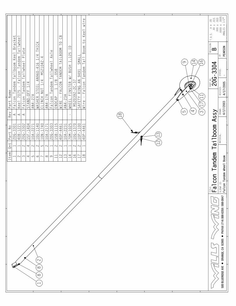
18
8
14
3
1213
1611
95 4
2
18
17
Item
Qnt
Part No
Rev
Part Name
11
20G-3301
AFalcon Tandem Tailboom Keel Bracket
21
40B-1221
AKeel 7075 - Falcon Tandem Tailwheel
32
20G-3302
AFalcon Tandem Tailwheel Plate
44
15F-1404
STAND-OFF 1/4
52
10A-2271
AN4-27A
62
10U-1140
WASHER STEEL AN960-416 1/4 THICK
75
10N-1740
CLINCH NUT 1/4 MS21042-4
82
10A-2171
AN4-17A
91
20G-3303
Falcon Tandem Tailwheel Axle
11
215B-1115
ENDCAP 1 1/8 .058
12
240P-4461
WIRE - FALCON TANDEM TAILBOOM TO CB
13
110A-2231
AN4-23A
14
170M-1025
-WHEEL FINSTER W/ BUSH 1.125 ID
16
210G-1370
MS20392-2C-37
17
210P-1100
SAFETY RING AN 9491 SMALL
18
140P-4461
Wire - Falcon Tandem Tail Boom to Keel wire
500
BLU
ERID
GE A
VE •
ORA
NGE,
CA
928
65 •
PH/
FAX
(714
) 998
-635
9 / 9
98-0
647
PART NO:
TITLE:
SLDDWF ID:
± .015
± 1/2
± .0005
± .003
DRAWN:
.XXX
ANGLES
.XXXX
.XX
T.U.S.
± .05
.X
Falc
on T
ande
m Wh
eel
Boom
4/17/2005
STATUS
:
-BY:
REVISED:
MATERIAL:
4/17/2003
REVISION:
20G-3304
PEARSO
NBFa
lcon
Tan
dem
Tail
boom
Ass
y