Embed Size (px)
Citation preview
THIS DOCUMENT IS AVAILABLE AT http://www.falcom.de/.
BOLERO-LT2 GSM/GPRS/GPS DEVICE
Hardware Description
Version 1.0.0; Created: Thursday 11 August 2011
BOLERO-LT2 Hardware Description Version 1.0.0
Table Of Contents
1 INTRODUCTION .....................................................................................6
1.1 GENERAL ...............................................................................................................................6
1.2 CIRCUIT CONCEPT ......................................................................................................................7
1.3 USED ABBREVIATIONS .................................................................................................................9
1.4 RELATED DOCUMENTS ...............................................................................................................10
2 SECURITY .............................................................................................11
2.1 GENERAL INFORMATION .............................................................................................................11
2.2 EXPOSURE TO RF ENERGY ..........................................................................................................11
2.3 DRIVING ..............................................................................................................................11
2.4 ELECTRONIC DEVICES .................................................................................................................12
2.5 VEHICLE ELECTRONIC EQUIPMENT ...................................................................................................12
2.6 MEDICAL ELECTRONIC EQUIPMENT ..................................................................................................12
2.7 AIRCRAFT .............................................................................................................................12
2.8 CHILDREN .............................................................................................................................12
2.9 BLASTING AREAS .....................................................................................................................12
2.10 POTENTIALLY EXPLOSIVE ATMOSPHERES ..........................................................................................13
3 SAFETY STANDARDS ............................................................................14
4 TECHNICAL DATA .................................................................................15
4.1 GENERAL SPECIFICATIONS OF TERMINAL BOLERO-LT2 .......................................................................15
4.1.1 Power consumption .........................................................................................................16 4.1.2 Operating temperatures ..................................................................................................16
4.2 TECHNICAL SPECIFICATIONS OF GSM/GPRS ENGINE ...........................................................................17
4.3 GPS ENGINE FEATURES .............................................................................................................18
4.4 NMEA DATA MESSAGE ............................................................................................................19
5 BOLERO-LT2 APPLICATION INTERFACE .................................................20
5.1 POWER SUPPLY ......................................................................................................................20
5.1.1 Power supply pins (3 and 4) on the 6-pin connector .......................................................20 5.1.2 Automatic shutdown .......................................................................................................20 5.1.3 Power saving ....................................................................................................................21
5.2 DETERMINING THE EXTERNAL EQUIPMENT TYPE ..................................................................................21
6 HARDWARE INTERFACES .....................................................................22
6.1 5PIN CONNECTOR ....................................................................................................................22
6.1.1 Pin assignment on the 5pin connector ............................................................................22 6.1.2 How to use IGN pin (pin 5) ...............................................................................................23 6.1.3 Buttons & LEDs ...............................................................................................................24 6.1.4 SIM card interface ............................................................................................................25 6.1.5 Special pin description .....................................................................................................25
This confidential document is a property of FALCOM and may not be copied or circulated without previous permission.
Page 2
BOLERO-LT2 Hardware Description Version 1.0.0
6.1.5.1 Serial communication signals (RxA, TxA) ....................................................................................................25
6.2 MOUNTING THE BOLERO-LT2 DEVICE ........................................................................................26
7 APPENDIX ............................................................................................27
7.1 SCHEMATICS ..........................................................................................................................27
7.1.1 Installation guidance for 6-pin connector ........................................................................27
This confidential document is a property of FALCOM and may not be copied or circulated without previous permission.
Page 3
BOLERO-LT2 Hardware Description Version 1.0.0
Version history:
This table provides a summary of the document revisions.
Version Author Changes Created-
1.0.0 F. Beqiri - Initial release 11/08/2011
This confidential document is a property of FALCOM and may not be copied or circulated without previous permission.
Page 4
BOLERO-LT2 Hardware Description Version 1.0.0
Cautions
Information furnished herein by FALCOM is believed to be accurate and reliable. However, no responsibility is assumed for its use. Please, read carefully the safety precautions.If you have any technical questions regarding this document or the product described in it, please contact your vendor.General information about FALCOM and its range of products are available at the following Internet address: http://www.falcom.de/
Trademarks
Some mentioned products are registered trademarks of their respective companies.
Copyright
This documentation is copyrighted by FALCOM WIRELESS COMMUNICATIONS GmbH with all rights reserved. No part of this documentation may be produced in any form without the prior written permission of FALCOM WIRELESS COMMUNICATIONS GmbH.
FALCOM Wireless Communications GmbH.
No patent liability is assumed with respect to the use of the information contained herein.
Note
Specifications and information given in this document are subject to change by FALCOM without notice.
This confidential document is a property of FALCOM and may not be copied or circulated without previous permission.
Page 5
BOLERO-LT2 Hardware Description Version 1.0.0
1 INTRODUCTION
This product manual is only addressed to qualified personnel which is well skilled in electronical/electrical installation and not addressed to private consumers/end users. The installation, implementing or setting into operation of the product can only be performed by this qualified personnel.
The status of the product described in the data sheet may have changed since publication of the data sheet and therefore information in this data sheet on product status may be outdated. The latest information of the product is published on the download area of the FALCOM website.
1.1 General
This description is focused on the GSM/GPRS and GPS terminal BOLERO-LT2 from FALCOM GmbH. It contains a variety of information about hardware concepts and issues of the BOLERO-LT2 device.
In order quickly to start and immediately and comprehensive to use all functions and to avoid any mistakes of BOLERO-LT2 device on your utilization, we recommend to read the following references and suggestions for using your new BOLERO-LT2 device.
BOLERO-LT2 consists of a Quad-band GSM/GPRS engine that works on the four frequencies GSM 850/900/1800/1900 MHz, a 50 channel high sensitive GPS core based on µ-blox engine and an embedded configurable software that provides many features for using location-based applications. The new device can be easily integrated into a variety of new applications stretching from real-time navigation and positioning to remote tracking and monitoring. It is designed for indoor use and ideal for fixed installation. The device concept is targeting for direct implementation as a mobile client in a wide range of high volume, low-cost, flexible system solutions like AVL, fleet management, vehicle security and recovery and other related area. The tracking functionality of the embedded mobile client application is combined with variety of alert messaging capabilities. The configurable alert messages contain current position of the device and many status reports. The physical interface to the terminal application is made through a 5pin connector. It provides a serial interface giving you maximum flexibility for local use such as controlling the terminal, receiving GPS location data, transferring data and 2 digital inputs for monitoring the ignition key of your vehicle and main power (car battery) failure. Depending on how the system BOLERO-LT2 is set up, their corresponding events can be used for a wide variety of notification purposes.
The embedded software the embedded software can be controlled by word like “PFAL” commands needed for executing particular actions, reading or setting particular configurations into the BOLERO-LT2 device. These commands are valid for all kinds of operations including Serial, SMS, CSD, TCP and SMTP.
BOLERO-LT2 provides Geofence features for territory management, route verification, prohibited locations, parking area and more with exception reporting to a wide variety of events, such as arrivals, departures, deliveries, pick-ups, illegal entries, unauthorized movement, etc.. BOLERO-LT2 contains a data-logger that enables you to archive unique locations in sequence for up to 45 days for later analysis and evaluation (for example, with an archive interval up to 20 sec.).
BOLERO-LT2 terminal can be implemented into any asset platform, including:
- Trailers
- Trucks
- Delivery vans
- Rail cars
- as well as other industrial monitoring installations.
This confidential document is a property of FALCOM and may not be copied or circulated without previous permission.
Page 6
BOLERO-LT2 Hardware Description Version 1.0.0
and it can be used in a variety of applications, including:
• Real time online tracking
• Fleet management / monitoring
• Security / emergency services
• Real time satellite navigation
• Territory management
• Personalized drivers logbook
• Route verification
• Trip management / distance calculations
• Theft protection
• Toll collection / pay as you drive
BOLERO-LT2 - EVALKIT provides an easy and efficient way to evaluate and configure all system parameters of the mobile client. The configuration of the BOLERO-LT2 can be done locally via serial link or remotely via the GSM network and Internet. The BOLERO-LT2 concept reduces the efforts for the creation of a turn key tracking and security solution to the definition of the server (dispatcher) application. In this way the time-to-market, the design-in risk and the total cost of solution are substantially reduced.
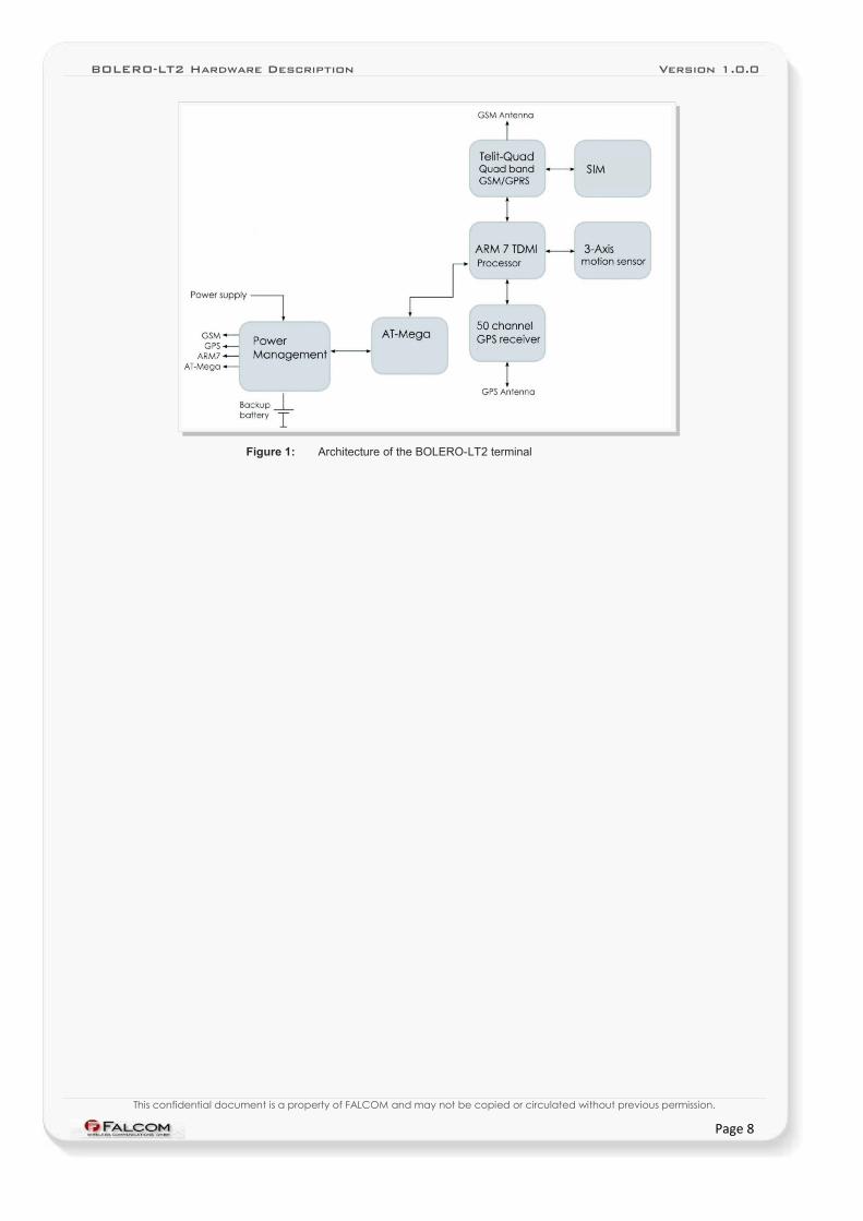
1.2 Circuit concept
The BOLERO-LT2 architecture includes the following major functional components (see Fig. 1):
ARCHITECTURE INTEGRATES:➢ High-performance Quad-Band GSM/GPRS core,
➢ High sensitivity 50 channel µ-blox,
➢ ARM7TDMI Processor (at speed 25MHz) that controls all functions of the system,
➢ Internal SIM card reader (1.8V and 3V),
➢ Internal GSM antenna,
➢ Internal GPS antenna,
➢ 500 mAh Li-Polymer rechargeable battery,
Options to BOLERO-LT2➢ 3D motion sensor
Physical interfaces:➢ Power supply line,
➢ 1x ON/OFF button,
➢ 1 x Ignition;
➢ RS232 port (RX, TX, GND)
➢ SIM Card reader (Type: Molex-91228-0002 small SIM Card)
➢ LED status indicators.
This confidential document is a property of FALCOM and may not be copied or circulated without previous permission.
Page 7
BOLERO-LT2 Hardware Description Version 1.0.0
Figure 1: Architecture of the BOLERO-LT2 terminal
This confidential document is a property of FALCOM and may not be copied or circulated without previous permission.
Page 8
BOLERO-LT2 Hardware Description Version 1.0.0
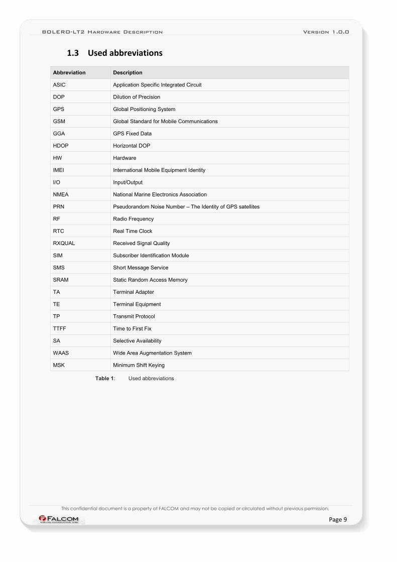
1.3 Used abbreviations
Abbreviation Description
ASIC Application Specific Integrated Circuit
DOP Dilution of Precision
GPS Global Positioning System
GSM Global Standard for Mobile Communications
GGA GPS Fixed Data
HDOP Horizontal DOP
HW Hardware
IMEI International Mobile Equipment Identity
I/O Input/Output
NMEA National Marine Electronics Association
PRN Pseudorandom Noise Number – The Identity of GPS satellites
RF Radio Frequency
RTC Real Time Clock
RXQUAL Received Signal Quality
SIM Subscriber Identification Module
SMS Short Message Service
SRAM Static Random Access Memory
TA Terminal Adapter
TE Terminal Equipment
TP Transmit Protocol
TTFF Time to First Fix
SA Selective Availability
WAAS Wide Area Augmentation System
MSK Minimum Shift Keying
Table 1: Used abbreviations
This confidential document is a property of FALCOM and may not be copied or circulated without previous permission.
Page 9
BOLERO-LT2 Hardware Description Version 1.0.0
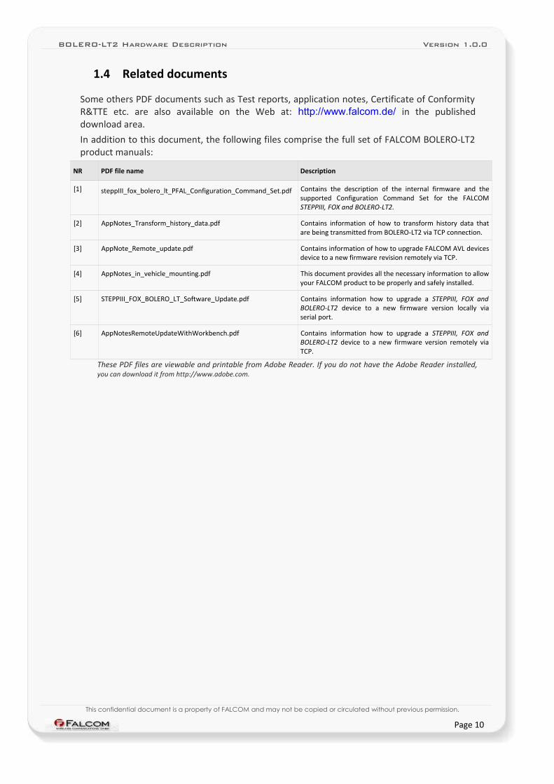
1.4 Related documents
Some others PDF documents such as Test reports, application notes, Certificate of Conformity R&TTE etc. are also available on the Web at: http://www.falcom.de/ in the published download area.
In addition to this document, the following files comprise the full set of FALCOM BOLERO-LT2 product manuals:
NR PDF file name Description
[1] steppIII_fox_bolero_lt_PFAL_Configuration_Command_Set.pdf Contains the description of the internal firmware and the supported Configuration Command Set for the FALCOM STEPPIII, FOX and BOLERO-LT2.
[2] AppNotes_Transform_history_data.pdf Contains information of how to transform history data that are being transmitted from BOLERO-LT2 via TCP connection.
[3] AppNote_Remote_update.pdf Contains information of how to upgrade FALCOM AVL devices device to a new firmware revision remotely via TCP.
[4] AppNotes_in_vehicle_mounting.pdf This document provides all the necessary information to allow your FALCOM product to be properly and safely installed.
[5] STEPPIII_FOX_BOLERO_LT_Software_Update.pdf Contains information how to upgrade a STEPPIII, FOX and BOLERO-LT2 device to a new firmware version locally via serial port.
[6] AppNotesRemoteUpdateWithWorkbench.pdf Contains information how to upgrade a STEPPIII, FOX and BOLERO-LT2 device to a new firmware version remotely via TCP.
These PDF files are viewable and printable from Adobe Reader. If you do not have the Adobe Reader installed, you can download it from http://www.adobe.com.
This confidential document is a property of FALCOM and may not be copied or circulated without previous permission.
Page 10
BOLERO-LT2 Hardware Description Version 1.0.0
2 SECURITY
IMPORTANT FOR THE EFFICIENT AND SAFE OPERATION OF YOUR GSM-MODEM, READ THIS INFORMATION BEFORE USE!
Your cellular engine BOLERO-LT2 is one of the most exciting and innovative electronic products ever developed. With it you can stay in contact with your office, your home, emergency services and others, wherever service is provided.
This chapter contains important information for the safe and reliable use of the BOLERO-LT2. Please read this chapter carefully before starting to use the cellular engine BOLERO-LT2.
2.1 General information
Your BOLERO-LT2 device utilizes the GSM/GPRS/GPS standard for cellular technology. GSM/GPRS is a newer radio frequency („RF“) technology than the current FM technology that has been used for radio communications for decades. The GSM standard has been established for use in the European community and elsewhere. Your modem is actually a low power radio transmitter and receiver. It sends out and receives radio frequency energy. When you use your modem, the cellular system handling your calls controls both the radio frequency and the power level of your cellular modem.
SIM cards are needed for the use of the acquired devices, which are not included in the scope of delivery of the device. The SIM cards can be acquired e.g. by specific providers. Additional costs can result from the use of the SIM cards which are to be borne by the purchaser (client) of the devices. The seller does not cover the extra costs for the use of the devices. The seller gives no recommendation for the use of specific SIM cards and is not liable for the fact that the devices are usable with all available SIM cards. The seller is also not liable for any other costs that are needed for the application of the customer in connection with this device.
2.2 Exposure to RF energy
There has been some public concern about possible health effects of using a GSM modem. Although research on health effects from RF energy has focused for many years on the current RF technology, scientists have begun research regarding newer radio technologies, such as GSM. After existing research had been reviewed, and after compliance to all applicable safety standards had been tested, it has been concluded that the product is fit for use.
If you are concerned about exposure to RF energy there are things you can do to minimize exposure. Obviously, limiting the duration of your calls will reduce your exposure to RF energy. In addition, you can reduce RF exposure by operating your cellular modem efficiently by following the guidelines below.
2.3 Driving
Check the laws and regulations on the use of cellular devices in the area where you drive. Always obey them. Also, when using your modem while driving, please pay full attention to driving, pull off the road and park before making or answering a call if driving conditions so require. When applications are prepared for mobile use they should fulfil road-safety instructions of the current law!
This confidential document is a property of FALCOM and may not be copied or circulated without previous permission.
Page 11
BOLERO-LT2 Hardware Description Version 1.0.0
2.4 Electronic devices
Most electronic equipment, for example in hospitals and motor vehicles is shielded from RF energy. However, RF energy may affect some malfunctioning or improperly shielded electronic equipment.
2.5 Vehicle electronic equipment
Check your vehicle manufacturer’s representative to determine if any on board electronic equipment is adequately shielded from RF energy.
2.6 Medical electronic equipment
Consult the manufacturer of any personal medical devices (such as pacemakers, hearing aids, etc.) to determine if they are adequately shielded from external RF energy.
Turn your BOLERO-LT2 device OFF in health care facilities when any regulations posted in the area instruct you to do so. Hospitals or health care facilities may be using RF monitoring equipment.
2.7 Aircraft
Turn your BOLERO-LT2 OFF before boarding any aircraft.
Use it on the ground only with crew permission.
Do not use it in the air.
To prevent possible interference with aircraft systems, Federal Aviation Administration (FAA) regulations require you to have permission from a crew member to use your modem while the plane is on the ground. To prevent interference with cellular systems, local RF regulations prohibit using your modem whilst airborne.
2.8 Children
Do not allow children to play with your BOLERO-LT2 device. It is not a toy. Children could hurt themselves or others (by poking themselves or others in the eye with the antenna, for example). Children could damage the modem or make calls that increase your modem bills.
2.9 Blasting areas
To avoid interfering with blasting operations, turn your unit OFF when in a “blasting area” or in areas posted: „turn off two-way radio“. Construction crew often use remote control RF devices to set off explosives.
This confidential document is a property of FALCOM and may not be copied or circulated without previous permission.
Page 12
BOLERO-LT2 Hardware Description Version 1.0.0
2.10 Potentially explosive atmospheres
Turn your BOLERO-LT2 device OFF when in any area with a potentially explosive atmosphere. It is rare, but your modem or its accessories could generate sparks. Sparks in such areas could cause an explosion or fire resulting in bodily injury or even death.
Areas with a potentially explosive atmosphere are often, but not always, clearly marked. They include fuelling areas such as petrol stations; below decks on boats; fuel or chemical transfer or storage facilities; and areas where the air contains chemicals or particles, such as grain, dust or metal powders.
Do not transport or store flammable gas, liquid or explosives, in the compartment of your vehicle, which contains your modem or accessories.
Before using your modem in a vehicle powered by liquefied petroleum gas (such as propane or butane) ensure that the vehicle complies with the relevant fire and safety regulations of the country in which the vehicle is to be used.
This confidential document is a property of FALCOM and may not be copied or circulated without previous permission.
Page 13
BOLERO-LT2 Hardware Description Version 1.0.0
3 SAFETY STANDARDS
This GSM/GPS modem complies with all applicable RF safety standards.
The embedded GSM/GPRS/GPS modem meets the safety standards for RF receivers and the standards and recommendations for the protection of public exposure to RF electromagnetic energy established by government bodies and professional organizations, such as directives of the European Community, Directorate General V in matters of radio frequency electromagnetic energy.
This confidential document is a property of FALCOM and may not be copied or circulated without previous permission.
Page 14
BOLERO-LT2 Hardware Description Version 1.0.0
4 TECHNICAL DATA
4.1 General specifications of terminal BOLERO-LT2
Supply voltage range:
➢ Operating power supply voltage range of +10.8 V to +32.0V, suitable for direct connection to an automotive +12V or +24V DC power source (car battery).
Power saving :
➢ 7 different energy-saving modes - programmable with PFAL commands. For more details about about the description of power saving modes see chapter 5.1.3, "Power saving".
Operating temperature range: ➢ -40 °C to + 85 °C (see chapter 4.1.2 for further details)
Physical characteristics : ➢ Size: 85 mm x 56 mm x 24 mm (W x L x H)
➢ Weight: ca. 90 g
Physical Interfaces :
➢ 5pin on-board connector :✔ 1 x Ignition (with software - controlled feature),✔ 1 x Power supply (with software - controlled feature)✔ 1 x Serial port (Rx, Tx), Baud rate 4800...115200 bps
(default=57600 bps) controlled by firmware, 8 data bits, no parity, 1 stop bit, no flow control,
➢ SIM Card interface (for 1.8 V and 3 V SIM cards)
➢ 3 X LED indicators (free-programmable)
➢ 1 x ON/OFF button (free-programmable)
➢ Li-Polymer 500 mAh rechargeable battery.
Hardware options : ➢ 3D motion sensor (Compact motion sensor for measuring motion in
3 axises)
Casing :
➢ Fully shielded
Air humidity :
➢ 5% up to 95% non-condensing
Directive :
➢ RoHS compliant.
Firmware :
➢ Embedded TCP/IP stack (inc. TCP, IP, UDP and SMTP protocol),
➢ Accessible via PFAL commands,
➢ Upgradeable via serial port and remotely over-the-air.
This confidential document is a property of FALCOM and may not be copied or circulated without previous permission.
Page 15
BOLERO-LT2 Hardware Description Version 1.0.0
Memory :
➢ 8 Mbyte FLASH for configuration, data-logging and firmware storage
➢ 2 MByte RAM
Evaluation kit :
➢ The BOLERO-LT2 Evalkit is designed to test, evaluate and make basis configuration to enable remote monitoring/configuration of the FALCOM BOLERO-LT2. It provides a sample configuration for application (in preparation).
Supported protocols (see chapter 4.4):
➢ NMEA msg.: GLL, GGA, RMC, VTG, GSV, GSA
➢ FALCOM msg.: IOP, GSM, AREA, 3DP, BIN.
4.1.1 Power consumption
Test conditions for the BOLERO-LT2 device as a standard version:
Operating modes approx. [mA]
GSM Off / GPS Off / No alarms
GSM Off / GPS On / No alarms
GSM On / GPS Off / No alarms
GSM On / GPS On / No alarms
To Be Defined
To Be Defined
To Be Defined
To Be Defined
Table 2: Current consumption @ 12 VDC
Average current consumption in sleep mode
Sleep Modes approx. [mA]
IGN To Be Defined
Table 2.1: Current consumption for different sleep modes
4.1.2 Operating temperatures
Parameter Min. Typ. Max. Unit
Storage temperature -20 +25 +60 °C
Charging temperature 0 +25 +45 °C
Discharging temperature -20 +25 +60 °C
Table 3: Operating temperature
This confidential document is a property of FALCOM and may not be copied or circulated without previous permission.
Page 16
BOLERO-LT2 Hardware Description Version 1.0.0
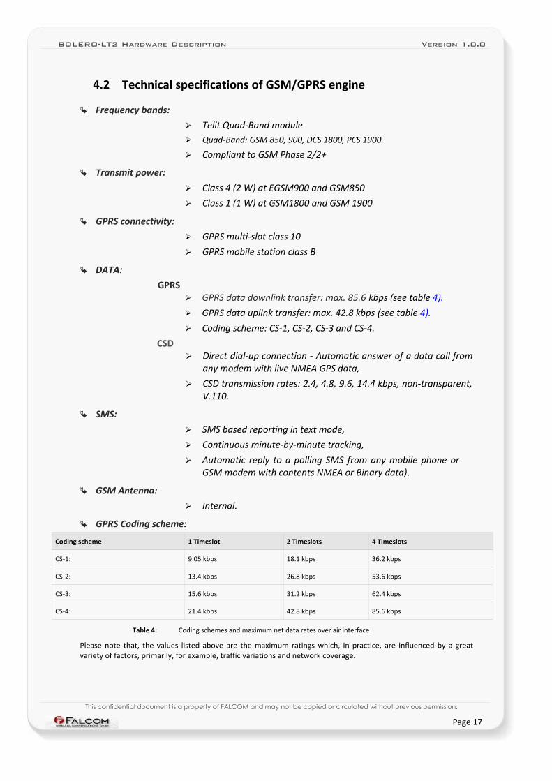
4.2 Technical specifications of GSM/GPRS engine
Frequency bands:
➢ Telit Quad-Band module➢ Quad-Band: GSM 850, 900, DCS 1800, PCS 1900.
➢ Compliant to GSM Phase 2/2+
Transmit power:
➢ Class 4 (2 W) at EGSM900 and GSM850
➢ Class 1 (1 W) at GSM1800 and GSM 1900
GPRS connectivity:
➢ GPRS multi-slot class 10
➢ GPRS mobile station class B
DATA:
GPRS➢ GPRS data downlink transfer: max. 85.6 kbps (see table 4).
➢ GPRS data uplink transfer: max. 42.8 kbps (see table 4).
➢ Coding scheme: CS-1, CS-2, CS-3 and CS-4.
CSD➢ Direct dial-up connection - Automatic answer of a data call from
any modem with live NMEA GPS data,
➢ CSD transmission rates: 2.4, 4.8, 9.6, 14.4 kbps, non-transparent, V.110.
SMS:
➢ SMS based reporting in text mode,
➢ Continuous minute-by-minute tracking,
➢ Automatic reply to a polling SMS from any mobile phone or GSM modem with contents NMEA or Binary data).
GSM Antenna:
➢ Internal.
GPRS Coding scheme:
Coding scheme 1 Timeslot 2 Timeslots 4 Timeslots
CS-1: 9.05 kbps 18.1 kbps 36.2 kbps
CS-2: 13.4 kbps 26.8 kbps 53.6 kbps
CS-3: 15.6 kbps 31.2 kbps 62.4 kbps
CS-4: 21.4 kbps 42.8 kbps 85.6 kbps
Table 4: Coding schemes and maximum net data rates over air interface
Please note that, the values listed above are the maximum ratings which, in practice, are influenced by a great variety of factors, primarily, for example, traffic variations and network coverage.
This confidential document is a property of FALCOM and may not be copied or circulated without previous permission.
Page 17
BOLERO-LT2 Hardware Description Version 1.0.0
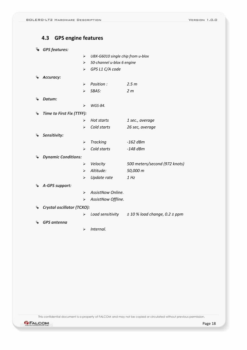
4.3 GPS engine features
GPS features:➢ UBX-G6010 single chip from u-blox
➢ 50-channel u-blox 6 engine
➢ GPS L1 C/A code
Accuracy:
➢ Position : 2.5 m
➢ SBAS: 2 m
Datum: ➢ WGS-84.
Time to First Fix (TTFF):
➢ Hot starts 1 sec., average
➢ Cold starts 26 sec, average
Sensitivity:
➢ Tracking -162 dBm
➢ Cold starts -148 dBm
Dynamic Conditions:
➢ Velocity 500 meters/second (972 knots)
➢ Altitude: 50,000 m
➢ Update rate 1 Hz
A-GPS support:
➢ AssistNow Online.
➢ AssistNow Offline.
Crystal oscillator (TCXO):
➢ Load sensitivity ± 10 % load change, 0.2 ± ppm
GPS antenna
➢ Internal.
This confidential document is a property of FALCOM and may not be copied or circulated without previous permission.
Page 18
BOLERO-LT2 Hardware Description Version 1.0.0
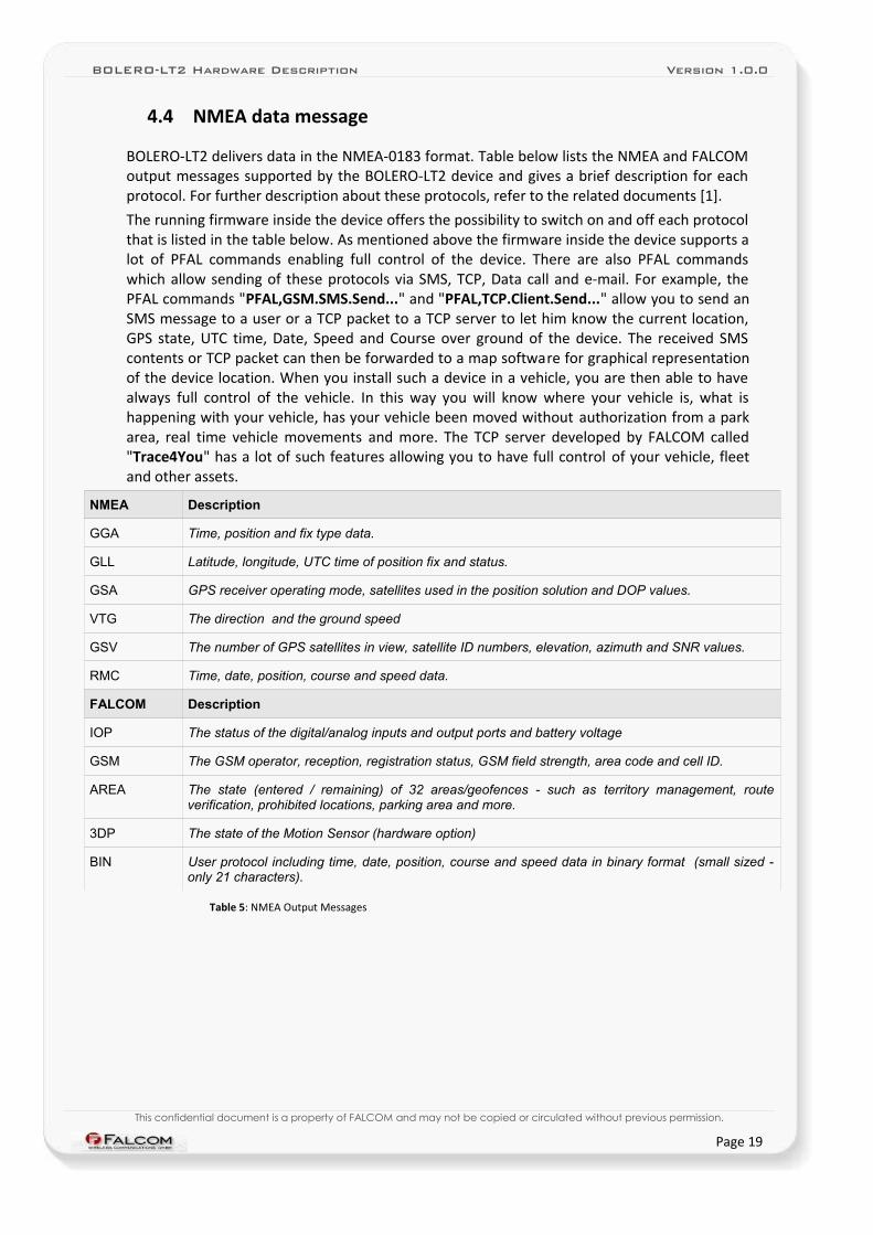
4.4 NMEA data message
BOLERO-LT2 delivers data in the NMEA-0183 format. Table below lists the NMEA and FALCOM output messages supported by the BOLERO-LT2 device and gives a brief description for each protocol. For further description about these protocols, refer to the related documents [1].
The running firmware inside the device offers the possibility to switch on and off each protocol that is listed in the table below. As mentioned above the firmware inside the device supports a lot of PFAL commands enabling full control of the device. There are also PFAL commands which allow sending of these protocols via SMS, TCP, Data call and e-mail. For example, the PFAL commands "PFAL,GSM.SMS.Send..." and "PFAL,TCP.Client.Send..." allow you to send an SMS message to a user or a TCP packet to a TCP server to let him know the current location, GPS state, UTC time, Date, Speed and Course over ground of the device. The received SMS contents or TCP packet can then be forwarded to a map software for graphical representation of the device location. When you install such a device in a vehicle, you are then able to have always full control of the vehicle. In this way you will know where your vehicle is, what is happening with your vehicle, has your vehicle been moved without authorization from a park area, real time vehicle movements and more. The TCP server developed by FALCOM called "Trace4You" has a lot of such features allowing you to have full control of your vehicle, fleet and other assets.
NMEA Description
GGA Time, position and fix type data.
GLL Latitude, longitude, UTC time of position fix and status.
GSA GPS receiver operating mode, satellites used in the position solution and DOP values.
VTG The direction and the ground speed
GSV The number of GPS satellites in view, satellite ID numbers, elevation, azimuth and SNR values.
RMC Time, date, position, course and speed data.
FALCOM Description
IOP The status of the digital/analog inputs and output ports and battery voltage
GSM The GSM operator, reception, registration status, GSM field strength, area code and cell ID.
AREA The state (entered / remaining) of 32 areas/geofences - such as territory management, route verification, prohibited locations, parking area and more.
3DP The state of the Motion Sensor (hardware option)
BIN User protocol including time, date, position, course and speed data in binary format (small sized - only 21 characters).
Table 5: NMEA Output Messages
This confidential document is a property of FALCOM and may not be copied or circulated without previous permission.
Page 19
BOLERO-LT2 Hardware Description Version 1.0.0
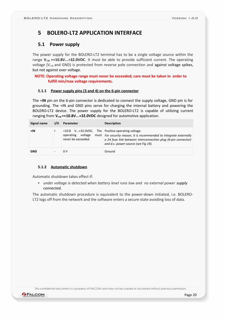
5 BOLERO-LT2 APPLICATION INTERFACE
5.1 Power supply
The power supply for the BOLERO-LT2 terminal has to be a single voltage source within the range V+IN =+10.8V...+32.0VDC. It must be able to provide sufficient current. The operating voltage (V+IN and GND) is protected from reverse pole connection and against voltage spikes, but not against over voltage.
NOTE: Operating voltage range must never be exceeded; care must be taken in order to fulfill min/max voltage requirements.
5.1.1 Power supply pins (3 and 4) on the 6-pin connector
The +IN pin on the 6-pin connector is dedicated to connect the supply voltage, GND pin is for grounding. The +IN and GND pins serve for charging the internal battery and powering the BOLERO-LT2 device. The power supply for the BOLERO-LT2 is capable of utilizing current ranging from V+IN =+10.8V...+32.0VDC designed for automotive application.
Signal name I/O Parameter Description
+IN I +10.8 V...+32.0VDC. The operating voltage must never be exceeded.
Positive operating voltage. For security reason, it is recommended to integrate externally a 2A fuse link between interconnection plug (6-pin connector) and d.c.-power source (see Fig 19).
GND - 0 V Ground
5.1.2 Automatic shutdown
Automatic shutdown takes effect if:
• under voltage is detected when battery level runs low and no external power supply connected.
The automatic shutdown procedure is equivalent to the power-down initiated, i.e. BOLERO-LT2 logs off from the network and the software enters a secure state avoiding loss of data.
This confidential document is a property of FALCOM and may not be copied or circulated without previous permission.
Page 20
BOLERO-LT2 Hardware Description Version 1.0.0
5.1.3 Power saving
SLEEP mode reduces the functionality of the modules of the BOLERO-LT2 device to a minimum and, thus, minimizes the current consumption to the lowest level. Settings can be made using the $PFAL,Sys.Device.Sleep command. For details, see example in table below.
Following SLEEP modes are supported by the BOLERO-LT2 device:
Modes Description
IGN Device wakes up when IGN (pin 5) changes its digital level from Low to High (performs a rising edge).
Ring Device wakes up when the GSM module receives a voice call or an SMS.
Timer=1:20:00 Device wakes up after the defined time has expired.
Motion=5,20,20 Device wakes up when motion is detected.
ExtPwrDetect Device wakes up when external power (higher than 9 V) is connected to the device.
ExtPwrDrop Device wakes up when external power is disconnected or it drops below 8 V.
DiWu Device wakes up when ON/OFF button is pressed.
Example $PFAL,Sys.Device.Sleep=IGN+Ring+Timer=1:20:00$PFAL,Sys.Device.Sleep=DiWu
IMPORTANT: The sleep and wake-up procedures are quite different depending on the selected sleep mode. Please keep in mind the power saving with the parameter "Ring" works properly only when PIN authentication has been done and the device is registered in the GSM network. If you attempt to activate power saving while the device is not registered in the GSM network, the SIM card is not inserted or the PIN not correctly entered, the device responds error "ring shutdown aborted due to bad GSM coverage" and the power saving does not take place. For more details, refer to the manual "steppIII_fox_bolero_lt_PFAL_Configuration_Command_Set.pdf".
NOTE: The internal battery of the BOLERO-LT2 must have enough power to safely wake up the device from a sleep mode. If the internal battery of the BOLERO-LT2 device does not have enough power, the device can not complete the wake up operation.
5.2 Determining the External Equipment Type
Before you connect the serial port pins on the aforementioned terminals (DCE units) to external equipment, you need to determine if the serial port of the external hardware is configured as DTE or DCE. The FALCOM BOLERO-LT2 is designed for use as a DCE. Based on the conventions for DCE-DTE connections it communicates with the customer application (DTE) using the following signals:
BOLERO-LT2 Terminal (DCE) to Application (DTE)
RxA <---------- TXD
TxA ----------> RXD
Table 6: The signalling definitions between DTE and DCE.
This confidential document is a property of FALCOM and may not be copied or circulated without previous permission.
Page 21
BOLERO-LT2 Hardware Description Version 1.0.0
6 HARDWARE INTERFACES
6.1 5pin connector
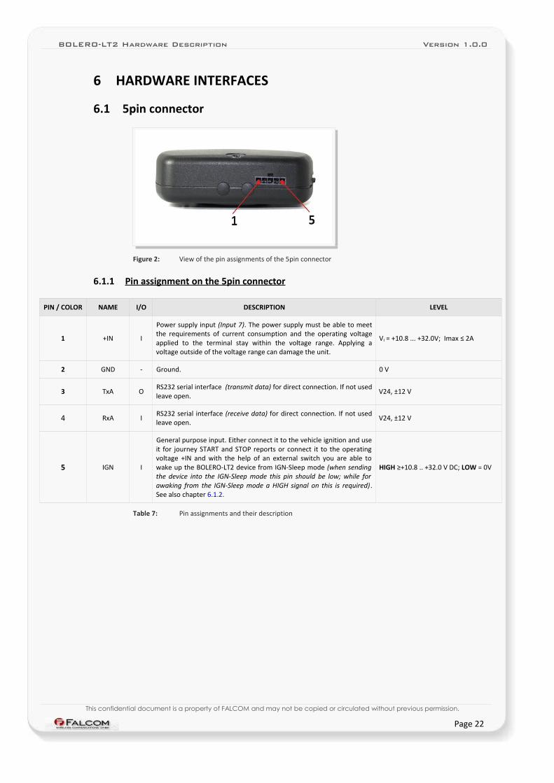
Figure 2: View of the pin assignments of the 5pin connector
6.1.1 Pin assignment on the 5pin connector
PIN / COLOR NAME I/O DESCRIPTION LEVEL
1 +IN I
Power supply input (Input 7). The power supply must be able to meet the requirements of current consumption and the operating voltage applied to the terminal stay within the voltage range. Applying a voltage outside of the voltage range can damage the unit.
VI = +10.8 ... +32.0V; Imax ≤ 2A
2 GND - Ground. 0 V
3 TxA ORS232 serial interface (transmit data) for direct connection. If not used leave open.
V24, ±12 V
4 RxA IRS232 serial interface (receive data) for direct connection. If not used leave open.
V24, ±12 V
5 IGN I
General purpose input. Either connect it to the vehicle ignition and use it for journey START and STOP reports or connect it to the operating voltage +IN and with the help of an external switch you are able to wake up the BOLERO-LT2 device from IGN-Sleep mode (when sending the device into the IGN-Sleep mode this pin should be low; while for awaking from the IGN-Sleep mode a HIGH signal on this is required). See also chapter 6.1.2.
HIGH ≥+10.8 .. +32.0 V DC; LOW = 0V
Table 7: Pin assignments and their description
This confidential document is a property of FALCOM and may not be copied or circulated without previous permission.
Page 22
BOLERO-LT2 Hardware Description Version 1.0.0
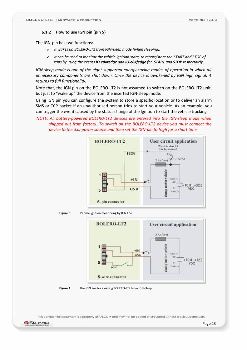
6.1.2 How to use IGN pin (pin 5)
The IGN-pin has two functions:✔ It wakes up BOLERO-LT2 from IGN-sleep mode (when sleeping),
✔ It can be used to monitor the vehicle ignition state, to report/store the START and STOP of trips by using the events IO.e8=redge and IO.e8=fedge for START and STOP respectively.
IGN-sleep mode is one of the eight supported energy-saving modes of operation in which all unnecessary components are shut down. Once the device is awakened by IGN high signal, it returns to full functionality.
Note that, the IGN pin on the BOLERO-LT2 is not assumed to switch on the BOLERO-LT2 unit, but just to “wake up” the device from the inserted IGN-sleep mode.
Using IGN pin you can configure the system to store a specific location or to deliver an alarm SMS or TCP packet if an unauthorised person tries to start your vehicle. As an example, you can trigger the event caused by the status change of the Ignition to start the vehicle tracking.
NOTE: All battery-powered BOLERO-LT2 devices are entered into the IGN-sleep mode when shipped out from factory. To switch on the BOLERO-LT2 device you must connect the device to the d.c.-power source and then set the IGN-pin to High for a short time.
Figure 3: Vehicle ignition monitoring by IGN line
Figure 4: Use IGN line for awaking BOLERO-LT2 from IGN-Sleep
This confidential document is a property of FALCOM and may not be copied or circulated without previous permission.
Page 23
BOLERO-LT2 Hardware Description Version 1.0.0
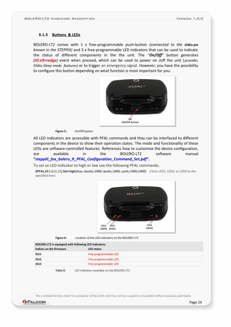
6.1.3 Buttons & LEDs
BOLERO-LT2 comes with 1 x free-programmable push-button (connected to the DiWu-pin
known in the STEPPIII) and 3 x free-programmable LED indicators that can be used to indicate the status of different components in the the unit. The "On/Off" button generates (IO.e9=redge) event when pressed, which can be used to power on /off the unit (provides DiWu-Sleep mode features) or to trigger an emergency signal. However, you have the possibility to configure this button depending on what function is most important for you.
Figure 5: On/Off button
All LED indicators are accessible with PFAL commands and they can be interfaced to different components in the device to show their operation states. The mode and functionality of these LEDs are software-controlled features. References how to customize the device configuration, are available in the BOLERO-LT2 software manual “steppIII_fox_bolero_lt_PFAL_Configuration_Command_Set.pdf”.
To set an LED indicator to high or low use the following PFAL commands:$PFAL,IO11[12,13].Set=high[low; hpulse,1000; lpulse,1000; cyclic,1000,1000] //sets LED1, LED2, or LED3 to the specified level.
Figure 6: Location of the LED indicators on the BOLERO-LT2
BOLERO-LT2 is equipped with following LED indicators:
Indices on the firmware LED status
IO11 Free programmable LED
IO12 Free programmable LED
IO13 Free programmable LED
Table 8: LED indicators available on the BOLERO-LT2
This confidential document is a property of FALCOM and may not be copied or circulated without previous permission.
Page 24
BOLERO-LT2 Hardware Description Version 1.0.0
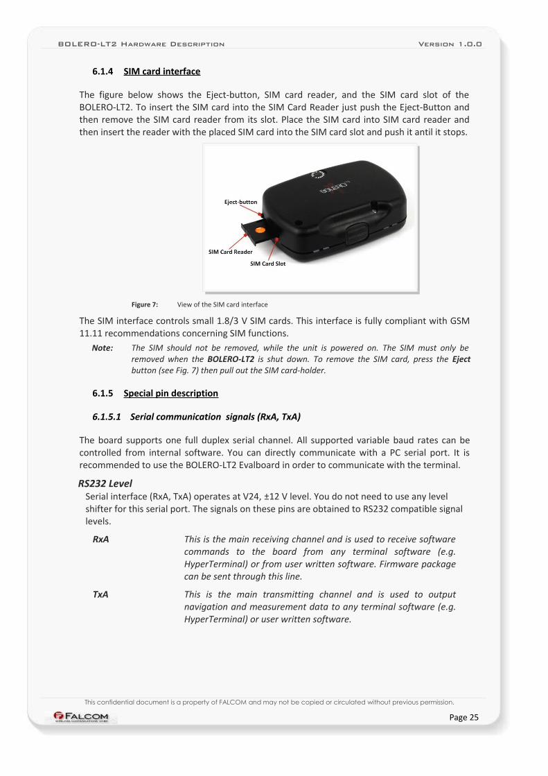
6.1.4 SIM card interface
The figure below shows the Eject-button, SIM card reader, and the SIM card slot of the BOLERO-LT2. To insert the SIM card into the SIM Card Reader just push the Eject-Button and then remove the SIM card reader from its slot. Place the SIM card into SIM card reader and then insert the reader with the placed SIM card into the SIM card slot and push it antil it stops.
Figure 7: View of the SIM card interface
The SIM interface controls small 1.8/3 V SIM cards. This interface is fully compliant with GSM 11.11 recommendations concerning SIM functions.
Note: The SIM should not be removed, while the unit is powered on. The SIM must only be removed when the BOLERO-LT2 is shut down. To remove the SIM card, press the Eject button (see Fig. 7) then pull out the SIM card-holder.
6.1.5 Special pin description
6.1.5.1 Serial communication signals (RxA, TxA)
The board supports one full duplex serial channel. All supported variable baud rates can be controlled from internal software. You can directly communicate with a PC serial port. It is recommended to use the BOLERO-LT2 Evalboard in order to communicate with the terminal.
RS232 LevelSerial interface (RxA, TxA) operates at V24, ±12 V level. You do not need to use any level shifter for this serial port. The signals on these pins are obtained to RS232 compatible signal levels.
RxA This is the main receiving channel and is used to receive software commands to the board from any terminal software (e.g. HyperTerminal) or from user written software. Firmware package can be sent through this line.
TxA This is the main transmitting channel and is used to output navigation and measurement data to any terminal software (e.g. HyperTerminal) or user written software.
This confidential document is a property of FALCOM and may not be copied or circulated without previous permission.
Page 25
BOLERO-LT2 Hardware Description Version 1.0.0
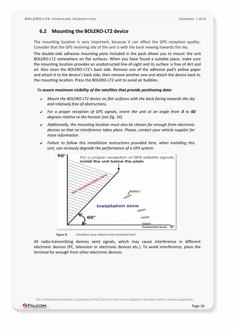
6.2 Mounting the BOLERO-LT2 device
The mounting location is very important, because it can affect the GPS reception quality. Consider that the GPS receiving site of the unit is with the back viewing towards the sky.
The double-side adhesive mounting plate included in the pack allows you to mount the unit BOLERO-LT2 somewhere on flat surfaces. When you have found a suitable place, make sure the mounting location provides an unobstructed line-of-sight and its surface is free of dirt and oil. Also clean the BOLERO-LT2’s back side. Remove one of the adhesive pad's yellow paper and attach it to the device’s back side, then remove another one and attach the device back to the mounting location. Press the BOLERO-LT2 unit to avoid air bubbles.
To assure maximum visibility of the satellites that provide positioning data:
✔ Mount the BOLERO-LT2 device on flat surfaces with the back facing towards the sky and relatively free of obstructions.
✔ For a proper reception of GPS signals, orient the unit at an angle from 0 to 60 degrees relative to the horizon (see fig. 14).
✔ Additionally, the mounting location must also be chosen far enough from electronic devices so that no interference takes place. Please, contact your vehicle supplier for more information.
✔ Failure to follow this installation instructions provided here, when installing this unit, can seriously degrade the performance of a GPS system .
Figure 8: Installation area relative to the horizontal level
All radio-transmitting devices send signals, which may cause interference in different electronic devices (PC, television or electronic devices etc.). To avoid interference, place the terminal far enough from other electronic devices.
This confidential document is a property of FALCOM and may not be copied or circulated without previous permission.
Page 26
BOLERO-LT2 Hardware Description Version 1.0.0
7 APPENDIX
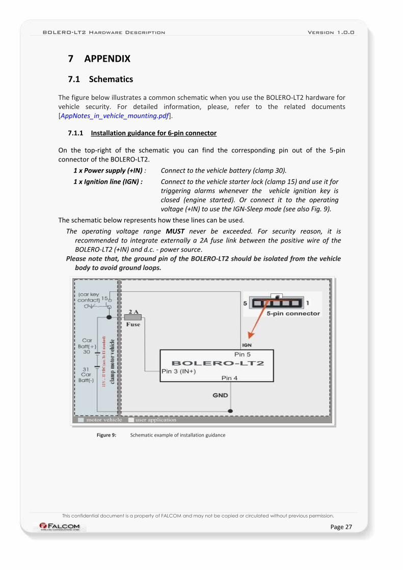
7.1 Schematics
The figure below illustrates a common schematic when you use the BOLERO-LT2 hardware for vehicle security. For detailed information, please, refer to the related documents [AppNotes_in_vehicle_mounting.pdf].
7.1.1 Installation guidance for 6-pin connector
On the top-right of the schematic you can find the corresponding pin out of the 5-pin connector of the BOLERO-LT2.
1 x Power supply (+IN) : Connect to the vehicle battery (clamp 30).
1 x Ignition line (IGN) : Connect to the vehicle starter lock (clamp 15) and use it for triggering alarms whenever the vehicle ignition key is closed (engine started). Or connect it to the operating voltage (+IN) to use the IGN-Sleep mode (see also Fig. 9).
The schematic below represents how these lines can be used.
The operating voltage range MUST never be exceeded. For security reason, it is recommended to integrate externally a 2A fuse link between the positive wire of the BOLERO-LT2 (+IN) and d.c. - power source.
Please note that, the ground pin of the BOLERO-LT2 should be isolated from the vehicle body to avoid ground loops.
Figure 9: Schematic example of installation guidance
This confidential document is a property of FALCOM and may not be copied or circulated without previous permission.
Page 27