Embed Size (px)
Citation preview
1
Failures of High Alloy Expansion Bellows in Refinery Catalytic Cracking Units
Gerald W. Wilks
Senior Metallurgy and Corrosion Engineer CITGO Petroleum Corporation
Lemont Refinery
Abstract Refinery fluidized bed catalytic cracking units (FCCUs) convert heavy, low value hydrocarbons into higher value fuels by heating the hydrocarbon to high temperatures with catalyst. Exposing the heavy hydrocarbons to heat and catalyst causes the hydrocarbon molecules to break apart or crack producing the higher value products. The cracking process is carried out at temperatures in the 510-565°C temperature range and regeneration of the catalyst occurs in the 690-735°C temperature range. The process involves movement of catalyst between the reactor vessel, the regenerator vessel. The unit requires large diameter piping runs, and significant lengths of piping. Expansion bellows are used in the piping systems to accommodate the movement of the piping that occurs as these units are started and shut down. Failures can occur due to fatigue, corrosion, stress corrosion cracking, creep, mechanical overloads, or metal embrittlement. This paper reviews causes of past failures and changes that can be made to expansion bellows design to prevent future failures. Keywords: Expansion bellows, sensitization, creep, stress corrosion cracking, fatigue, corrosion,
embrittlement, 321 stainless steel, 347 stainless steel, Inconel 625, Incoloy 800. 1. Background Crude oil is processed in refineries to produce a wide range of petroleum products, and the refining process begins with distillation of the crude in towers that operate at near atmospheric pressure and at reduced pressures. The distillation tower operating at near ambient pressure will be referred to as the “atmospheric distillation tower” in this paper and the term “vacuum distillation tower” will be used for the tower that operates at reduced pressure. These two distillation towers produce in process streams that have ranges of molecular weights. This paper is concerned with the process streams that are the feed to FCCUs and these streams are typically referred to as “gas oils”. Gas oils in refineries originate in both the primary and vacuum distillation towers and also can originate on other process units. For example, coking units produce gas oil products and some gas oil is also produced on the FCCU. The gas oil feed to FCCUs typically consists of hydrocarbons that have molecular weight in the 280 to 420 range. The core of the FCC process is two large pressure vessels that are called the reactor and the regenerator. Figure 1 is a simplified process diagram showing these large vessels on a FCCU[1]. The reactor and the regenerator are connected with large piping lines that are called “risers”. Risers are lined with refractory to provide erosion resistance, and these lines typically don’t contain expansion bellows. The overhead line from the reactor goes to the fractionator vessel where the products produced by the FCC are separated and routed to other units. The fractionator on a FCCU is very similar to the atmospheric distillation tower on a crude unit. The overhead line on the regenerator goes to a waste heat boiler where energy is extracted to produce steam. On some FCCUs the flue gas is routed first to a power recovery turbine where mechanical energy is extracted from the flue gas and used to compress air. This paper will review failures that occurred in expansion bellows that were located in the piping between the regenerator and the boiler and in the piping between the reactor and the fractionator.
2
To Fractionator
To Boiler
To Fractionator
To Boiler
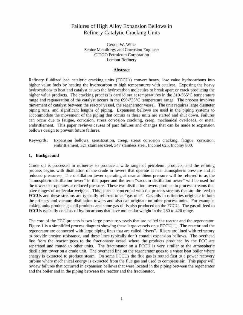
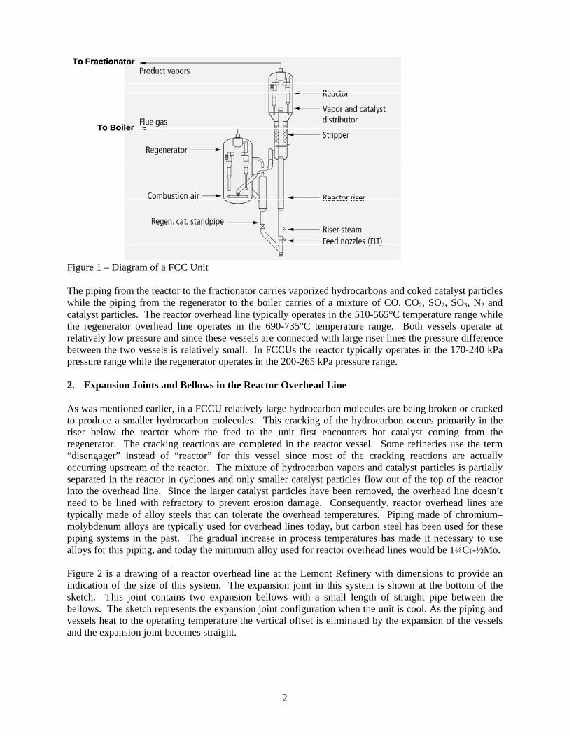
Figure 1 – Diagram of a FCC Unit The piping from the reactor to the fractionator carries vaporized hydrocarbons and coked catalyst particles while the piping from the regenerator to the boiler carries of a mixture of CO, CO2, SO2, SO3, N2 and catalyst particles. The reactor overhead line typically operates in the 510-565°C temperature range while the regenerator overhead line operates in the 690-735°C temperature range. Both vessels operate at relatively low pressure and since these vessels are connected with large riser lines the pressure difference between the two vessels is relatively small. In FCCUs the reactor typically operates in the 170-240 kPa pressure range while the regenerator operates in the 200-265 kPa pressure range. 2. Expansion Joints and Bellows in the Reactor Overhead Line As was mentioned earlier, in a FCCU relatively large hydrocarbon molecules are being broken or cracked to produce a smaller hydrocarbon molecules. This cracking of the hydrocarbon occurs primarily in the riser below the reactor where the feed to the unit first encounters hot catalyst coming from the regenerator. The cracking reactions are completed in the reactor vessel. Some refineries use the term “disengager” instead of “reactor” for this vessel since most of the cracking reactions are actually occurring upstream of the reactor. The mixture of hydrocarbon vapors and catalyst particles is partially separated in the reactor in cyclones and only smaller catalyst particles flow out of the top of the reactor into the overhead line. Since the larger catalyst particles have been removed, the overhead line doesn’t need to be lined with refractory to prevent erosion damage. Consequently, reactor overhead lines are typically made of alloy steels that can tolerate the overhead temperatures. Piping made of chromium–molybdenum alloys are typically used for overhead lines today, but carbon steel has been used for these piping systems in the past. The gradual increase in process temperatures has made it necessary to use alloys for this piping, and today the minimum alloy used for reactor overhead lines would be 1¼Cr-½Mo. Figure 2 is a drawing of a reactor overhead line at the Lemont Refinery with dimensions to provide an indication of the size of this system. The expansion joint in this system is shown at the bottom of the sketch. This joint contains two expansion bellows with a small length of straight pipe between the bellows. The sketch represents the expansion joint configuration when the unit is cool. As the piping and vessels heat to the operating temperature the vertical offset is eliminated by the expansion of the vessels and the expansion joint becomes straight.
3
Figure 2
This is a drawing of the reactor overhead line at the Lemont Refinery that shows the geometry of the system. The expansion joint is shown as it would be when the unit is not operating. The offset in piping elevation across the expansion joint is 0.253m when the system is cool. When the unit starts up and the vessels and piping come to operating temperature the expansion joint straightens. Both the reactor and the fractionator are hot wall design vessels so the expansion of these vessels results in changes in elevation at the points where these vessels connect to the piping. Also the overhead line is operating at high temperature so its expansion has to also be accommodated by the expansion joint. Fortunately, this system operates at relatively constant temperature and significant temperature changes only occur during start up and shut down events. Pressure changes also result in some changes in piping geometry, and this process does involve changes in pressure when there are changes in feed to the unit, and feed changes do occur frequently. The pressure swings that occur during feed changes are from 125 kPa to 205 kPa so the system does experience significant cyclic stresses that could lead to fatigue cracking of the bellows. Also, the unit has periodic shut downs and start ups when very high stresses are generated in the bellows. However, past investigations of bellows failures have never found evidence of fatigue cracking. So fatigue cracking is a risk for these bellows, but so far fatigue failures have not occurred. It could be that fatigue failures have not occurred because these bellows have been replaced frequently in the past. The bellows closest to the reactor was replaced in 1976, 1987, 2002 and 2010 while the bellows closest to the fractionator was replaced in 1987 and 2002 and 2010. These bellows may not have experienced enough stress cycles for fatigue cracking to occur because they were replaced so often. The failed bellows is shown in Figure 3 along with a sketch of the bellows that shows insulation, the external weather shielding and the internal erosion shielding. The sketch also shows that there are connections around the bellows that inject steam into the space between the bellows and the internal
Spent Catalyst to the
Regenerator
VesselSkirt
Support Structure
Regenerated Catalyst and
Hydrocarbon to the Reactor
ExpansionJoint
Sway Strut
Reactor
Sway Strut
Spring CanSupport
Sway Strut &Duct Support Ring
Sway Strut
Spring CanSupport
Trunnion Support
FCCU Reactor Overhead Line1.37m OD 14.3mm Thick 1¼Cr-½Mo
Spring CanSupport
Frac
tiona
tor
2 Bellows
7.2m ID
7m ID
~6m
14.7m
80m
4.8m
31m
5.05m
4
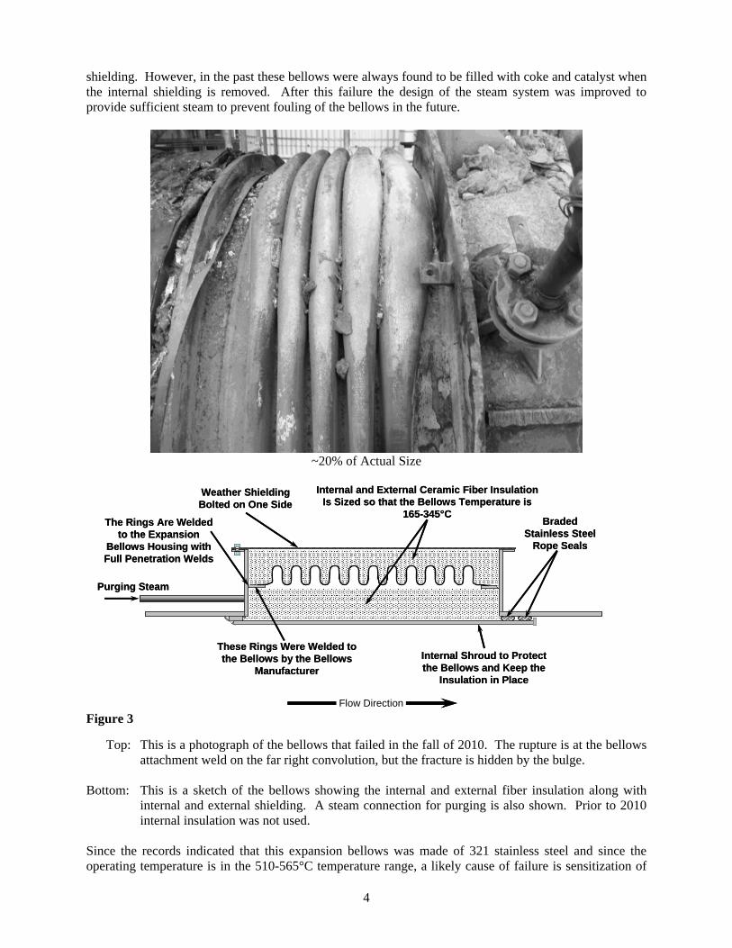
shielding. However, in the past these bellows were always found to be filled with coke and catalyst when the internal shielding is removed. After this failure the design of the steam system was improved to provide sufficient steam to prevent fouling of the bellows in the future.
~20% of Actual Size
Flow Direction
These Rings Were Welded to the Bellows by the Bellows
Manufacturer
Braded Stainless Steel
Rope Seals
Internal Shroud to Protect the Bellows and Keep the
Insulation in Place
Internal and External Ceramic Fiber Insulation Is Sized so that the Bellows Temperature is
165-345°C
Weather Shielding Bolted on One Side
The Rings Are Welded to the Expansion
Bellows Housing with Full Penetration Welds
Purging Steam
Figure 3 Top: This is a photograph of the bellows that failed in the fall of 2010. The rupture is at the bellows
attachment weld on the far right convolution, but the fracture is hidden by the bulge. Bottom: This is a sketch of the bellows showing the internal and external fiber insulation along with
internal and external shielding. A steam connection for purging is also shown. Prior to 2010 internal insulation was not used.
Since the records indicated that this expansion bellows was made of 321 stainless steel and since the operating temperature is in the 510-565°C temperature range, a likely cause of failure is sensitization of
5
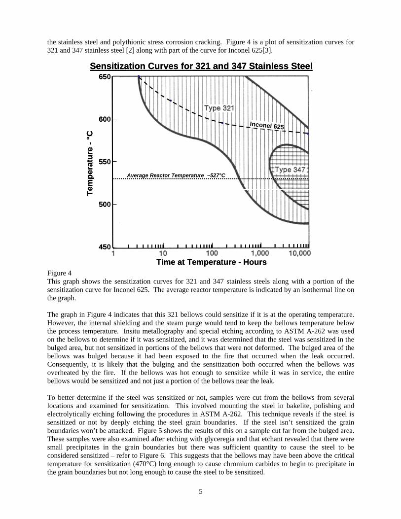
the stainless steel and polythionic stress corrosion cracking. Figure 4 is a plot of sensitization curves for 321 and 347 stainless steel [2] along with part of the curve for Inconel 625[3].
550
500
450
600
650
Average Reactor Temperature ~527°C
Time at Temperature - Hours
Tem
pera
ture
-°C
Sensitization Curves for 321 and 347 Stainless Steel
Inconel 625
550
500
450
600
650
Average Reactor Temperature ~527°C
Time at Temperature - Hours
Tem
pera
ture
-°C
Sensitization Curves for 321 and 347 Stainless Steel
Inconel 625
Figure 4 This graph shows the sensitization curves for 321 and 347 stainless steels along with a portion of the sensitization curve for Inconel 625. The average reactor temperature is indicated by an isothermal line on the graph. The graph in Figure 4 indicates that this 321 bellows could sensitize if it is at the operating temperature. However, the internal shielding and the steam purge would tend to keep the bellows temperature below the process temperature. Insitu metallography and special etching according to ASTM A-262 was used on the bellows to determine if it was sensitized, and it was determined that the steel was sensitized in the bulged area, but not sensitized in portions of the bellows that were not deformed. The bulged area of the bellows was bulged because it had been exposed to the fire that occurred when the leak occurred. Consequently, it is likely that the bulging and the sensitization both occurred when the bellows was overheated by the fire. If the bellows was hot enough to sensitize while it was in service, the entire bellows would be sensitized and not just a portion of the bellows near the leak. To better determine if the steel was sensitized or not, samples were cut from the bellows from several locations and examined for sensitization. This involved mounting the steel in bakelite, polishing and electrolytically etching following the procedures in ASTM A-262. This technique reveals if the steel is sensitized or not by deeply etching the steel grain boundaries. If the steel isn’t sensitized the grain boundaries won’t be attacked. Figure 5 shows the results of this on a sample cut far from the bulged area. These samples were also examined after etching with glyceregia and that etchant revealed that there were small precipitates in the grain boundaries but there was sufficient quantity to cause the steel to be considered sensitized – refer to Figure 6. This suggests that the bellows may have been above the critical temperature for sensitization (470°C) long enough to cause chromium carbides to begin to precipitate in the grain boundaries but not long enough to cause the steel to be sensitized.
6
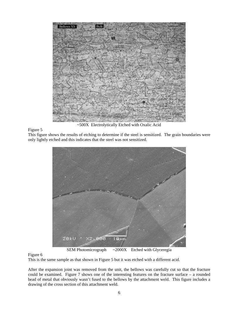
~500X Electrolytically Etched with Oxalic Acid Figure 5 This figure shows the results of etching to determine if the steel is sensitized. The grain boundaries were only lightly etched and this indicates that the steel was not sensitized.
SEM Photomicrograph ~2000X Etched with Glyceregia
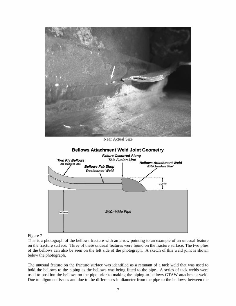
Figure 6 This is the same sample as that shown in Figure 5 but it was etched with a different acid. After the expansion joint was removed from the unit, the bellows was carefully cut so that the fracture could be examined. Figure 7 shows one of the interesting features on the fracture surface – a rounded bead of metal that obviously wasn’t fused to the bellows by the attachment weld. This figure includes a drawing of the cross section of this attachment weld.
7
Near Actual Size
1¼Cr-½Mo Pipe
Failure Occurred Along This Fusion LineTwo Ply Bellows
321 Stainless SteelBellows Fab Shop Resistance Weld
Bellows Attachment Weld Joint Geometry
~3.2mm
14.3mm
Bellows Attachment WeldE309 Stainless Steel
1¼Cr-½Mo Pipe
Failure Occurred Along This Fusion LineTwo Ply Bellows
321 Stainless SteelBellows Fab Shop Resistance Weld
Bellows Attachment Weld Joint Geometry
~3.2mm
14.3mm
Bellows Attachment WeldE309 Stainless Steel
Figure 7 This is a photograph of the bellows fracture with an arrow pointing to an example of an unusual feature on the fracture surface. Three of these unusual features were found on the fracture surface. The two plies of the bellows can also be seen on the left side of the photograph. A sketch of this weld joint is shown below the photograph. The unusual feature on the fracture surface was identified as a remnant of a tack weld that was used to hold the bellows to the piping as the bellows was being fitted to the pipe. A series of tack welds were used to position the bellows on the pipe prior to making the piping-to-bellows GTAW attachment weld. Due to alignment issues and due to the differences in diameter from the pipe to the bellows, between the
8
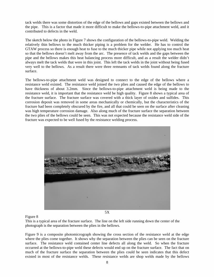
tack welds there was some distortion of the edge of the bellows and gaps existed between the bellows and the pipe. This is a factor that made it more difficult to make the bellows-to-pipe attachment weld, and it contributed to defects in the weld. The sketch below the photo in Figure 7 shows the configuration of the bellows-to-pipe weld. Welding the relatively thin bellows to the much thicker piping is a problem for the welder. He has to control the GTAW process so there is enough heat to fuse to the much thicker pipe while not applying too much heat so that the bellows doesn’t melt away from the arc. The presence of tack welds and the gaps between the pipe and the bellows makes this heat balancing process more difficult, and as a result the welder didn’t always melt the tack welds that were in this joint. This left the tack welds in the joint without being fused very well to the bellows. As a result there were three remnants of tack welds found along the fracture surface. The bellows-to-pipe attachment weld was designed to connect to the edge of the bellows where a resistance weld existed. The resistance weld joined the two plies and caused the edge of the bellows to have thickness of about 3.2mm. Since the bellows-to-pipe attachment weld is being made to the resistance weld, it is important that the resistance weld be high quality. Figure 8 shows a typical area of the fracture surface. The fracture surface was covered with a thick layer of oxides and sulfides. This corrosion deposit was removed in some areas mechanically or chemically, but the characteristics of the fracture had been completely obscured by the fire, and all that could be seen on the surface after cleaning was high temperature corrosion damage. Also along much of the fracture surface the separation between the two plies of the bellows could be seen. This was not expected because the resistance weld side of the fracture was expected to be well fused by the resistance welding process.
5X
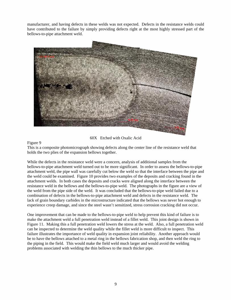
Figure 8 This is a typical area of the fracture surface. The line on the left side running down the center of the photograph is the separation between the plies in the bellows. Figure 9 is a composite photomicrograph showing the cross section of the resistance weld at the edge where the plies come together. It shows why the separation between the plies can be seen on the fracture surface. The resistance weld contained center line defects all along the weld. So when the fracture occurred at the bellows-to-pipe weld these defects would end up on the fracture surface. The fact that on much of the fracture surface the separation between the plies could be seen indicates that this defect existed in most of the resistance welds. These resistance welds are shop welds made by the bellows
9
manufacturer, and having defects in these welds was not expected. Defects in the resistance welds could have contributed to the failure by simply providing defects right at the most highly stressed part of the bellows-to-pipe attachment weld.
60X Etched with Oxalic Acid
Figure 9 This is a composite photomicrograph showing defects along the center line of the resistance weld that holds the two plies of the expansion bellows together. While the defects in the resistance weld were a concern, analysis of additional samples from the bellows-to-pipe attachment weld turned out to be more significant. In order to assess the bellows-to-pipe attachment weld, the pipe wall was carefully cut below the weld so that the interface between the pipe and the weld could be examined. Figure 10 provides two examples of the deposits and cracking found in the attachment welds. In both cases the deposits and cracks were aligned along the interface between the resistance weld in the bellows and the bellows-to-pipe weld. The photographs in the figure are a view of the weld from the pipe side of the weld. It was concluded that the bellows-to-pipe weld failed due to a combination of defects in the bellows-to-pipe attachment weld and defects in the resistance weld. The lack of grain boundary carbides in the microstructure indicated that the bellows was never hot enough to experience creep damage, and since the steel wasn’t sensitized, stress corrosion cracking did not occur. One improvement that can be made to the bellows-to-pipe weld to help prevent this kind of failure is to make the attachment weld a full penetration weld instead of a fillet weld. This joint design is shown in Figure 11. Making this a full penetration weld lowers the stress at the weld. Also, a full penetration weld can be inspected to determine the weld quality while the fillet weld is more difficult to inspect. This failure illustrates the importance of weld quality in expansion joint reliability. Another approach would be to have the bellows attached to a metal ring in the bellows fabrication shop, and then weld the ring to the piping in the field. This would make the field weld much larger and would avoid the welding problems associated with welding the thin bellows to the much thicker pipe.
10
~25 X
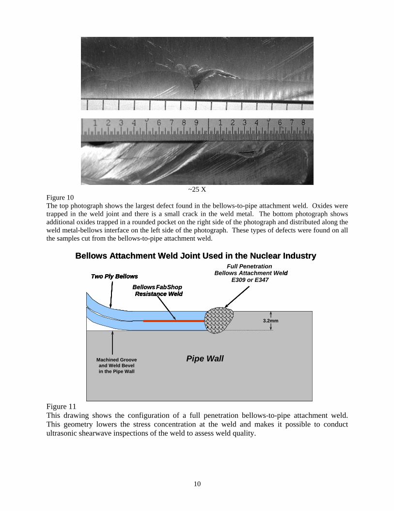
Figure 10 The top photograph shows the largest defect found in the bellows-to-pipe attachment weld. Oxides were trapped in the weld joint and there is a small crack in the weld metal. The bottom photograph shows additional oxides trapped in a rounded pocket on the right side of the photograph and distributed along the weld metal-bellows interface on the left side of the photograph. These types of defects were found on all the samples cut from the bellows-to-pipe attachment weld.
Pipe Wall
Two Ply Bellows
Bellows FabShop Resistance Weld
Bellows Attachment Weld Joint Used in the Nuclear Industry
~? ”
? ” Deep Machined Groove and Bevel on the Pipe Wall OD
Pipe Wall
Two Ply Bellows
Resistance Weld
Machined Groove and Weld Bevel in the Pipe Wall
Full Penetration Bellows Attachment Weld
E309 or E347
3.2mm
Pipe Wall
Two Ply Bellows
Bellows FabShop Resistance Weld
Bellows Attachment Weld Joint Used in the Nuclear Industry
~? ”
? ” Deep Machined Groove and Bevel on the Pipe Wall OD
Pipe Wall
Two Ply Bellows
Resistance Weld
Machined Groove and Weld Bevel in the Pipe Wall
Full Penetration Bellows Attachment Weld
E309 or E347
3.2mm
Figure 11 This drawing shows the configuration of a full penetration bellows-to-pipe attachment weld. This geometry lowers the stress concentration at the weld and makes it possible to conduct ultrasonic shearwave inspections of the weld to assess weld quality.
11
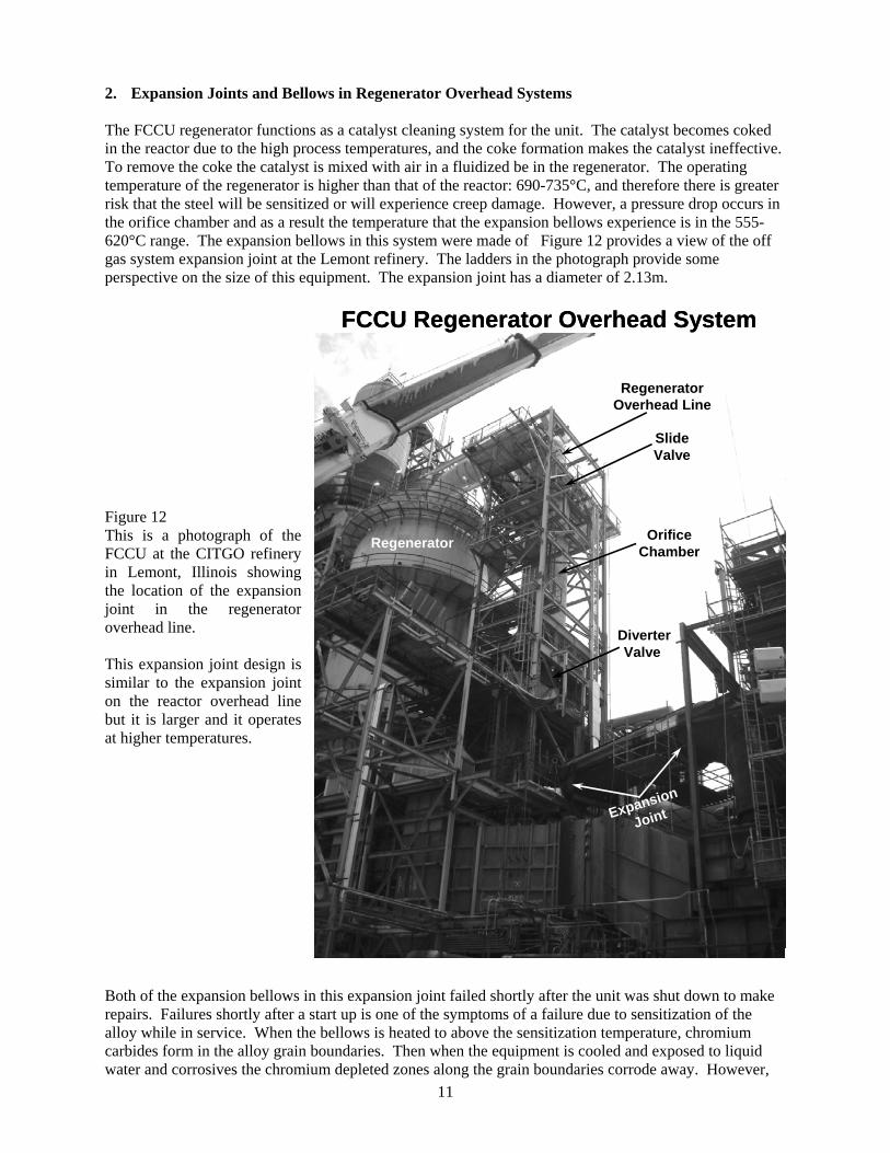
2. Expansion Joints and Bellows in Regenerator Overhead Systems The FCCU regenerator functions as a catalyst cleaning system for the unit. The catalyst becomes coked in the reactor due to the high process temperatures, and the coke formation makes the catalyst ineffective. To remove the coke the catalyst is mixed with air in a fluidized be in the regenerator. The operating temperature of the regenerator is higher than that of the reactor: 690-735°C, and therefore there is greater risk that the steel will be sensitized or will experience creep damage. However, a pressure drop occurs in the orifice chamber and as a result the temperature that the expansion bellows experience is in the 555-620°C range. The expansion bellows in this system were made of Figure 12 provides a view of the off gas system expansion joint at the Lemont refinery. The ladders in the photograph provide some perspective on the size of this equipment. The expansion joint has a diameter of 2.13m.
Figure 12 This is a photograph of the FCCU at the CITGO refinery in Lemont, Illinois showing the location of the expansion joint in the regenerator overhead line. This expansion joint design is similar to the expansion joint on the reactor overhead line but it is larger and it operates at higher temperatures. Both of the expansion bellows in this expansion joint failed shortly after the unit was shut down to make repairs. Failures shortly after a start up is one of the symptoms of a failure due to sensitization of the alloy while in service. When the bellows is heated to above the sensitization temperature, chromium carbides form in the alloy grain boundaries. Then when the equipment is cooled and exposed to liquid water and corrosives the chromium depleted zones along the grain boundaries corrode away. However,
Regenerator
Expansion
Joint
RegeneratorOverhead Line
FCCU Regenerator Overhead System
DiverterValve
OrificeChamber
Slide Valve
Regenerator
Expansion
Joint
RegeneratorOverhead Line
FCCU Regenerator Overhead System
DiverterValve
OrificeChamber
Slide Valve
12
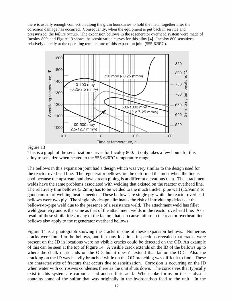
there is usually enough connection along the grain boundaries to hold the metal together after the corrosion damage has occurred. Consequently, when the equipment is put back in service and pressurized, the failure occurs. The expansion bellows in the regenerator overhead system were made of Incoloy 800, and Figure 13 shows the sensitization curves for this alloy [4]. Incoloy 800 sensitizes relatively quickly at the operating temperature of this expansion joint (555-620°C).
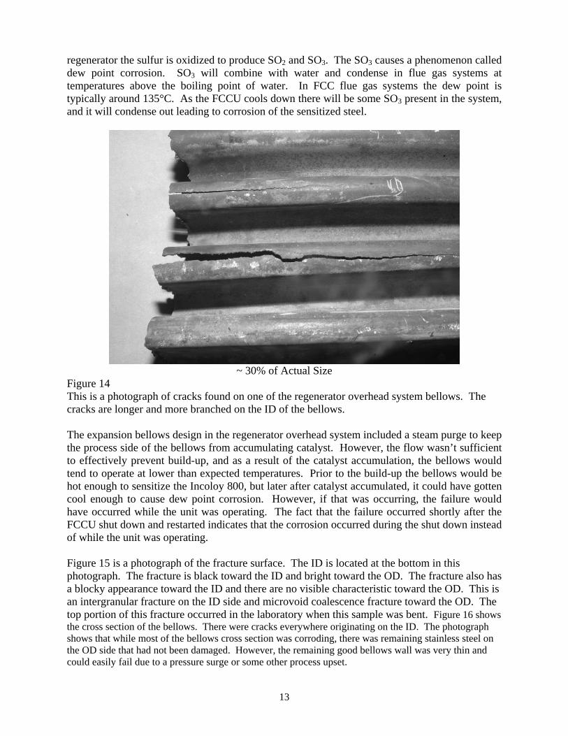
Figure 13 This is a graph of the sensitization curves for Incoloy 800. It only takes a few hours for this alloy to sensitize when heated to the 555-620°C temperature range. The bellows in this expansion joint had a design which was very similar to the design used for the reactor overhead line. The regenerator bellows are the deformed the most when the line is cool because the upstream and downstream piping is at different elevations then. The attachment welds have the same problems associated with welding that existed on the reactor overhead line. The relatively thin bellows (3.2mm) has to be welded to the much thicker pipe wall (15.9mm) so good control of welding heat is needed. These bellows are single ply while the reactor overhead bellows were two ply. The single ply design eliminates the risk of introducing defects at the bellows-to-pipe weld due to the presence of a resistance weld. The attachment weld has fillet weld geometry and is the same as that of the attachment welds in the reactor overhead line. As a result of these similarities, many of the factors that can cause failure in the reactor overhead line bellows also apply to the regenerator overhead bellows. Figure 14 is a photograph showing the cracks in one of these expansion bellows. Numerous cracks were found in the bellows, and in many locations inspections revealed that cracks were present on the ID in locations were no visible cracks could be detected on the OD. An example of this can be seen at the top of Figure 14. A visible crack extends on the ID of the bellows up to where the chalk mark ends on the OD, but it doesn’t extend that far on the OD. Also the cracking on the ID was heavily branched while on the OD branching was difficult to find. These are characteristics of fracture that occurs due to sensitization. Corrosion is occurring on the ID when water with corrosives condenses there as the unit shuts down. The corrosives that typically exist in this system are carbonic acid and sulfuric acid. When coke forms on the catalyst it contains some of the sulfur that was originally in the hydrocarbon feed to the unit. In the
13
regenerator the sulfur is oxidized to produce SO2 and SO3. The SO3 causes a phenomenon called dew point corrosion. SO3 will combine with water and condense in flue gas systems at temperatures above the boiling point of water. In FCC flue gas systems the dew point is typically around 135°C. As the FCCU cools down there will be some SO3 present in the system, and it will condense out leading to corrosion of the sensitized steel.
~ 30% of Actual Size
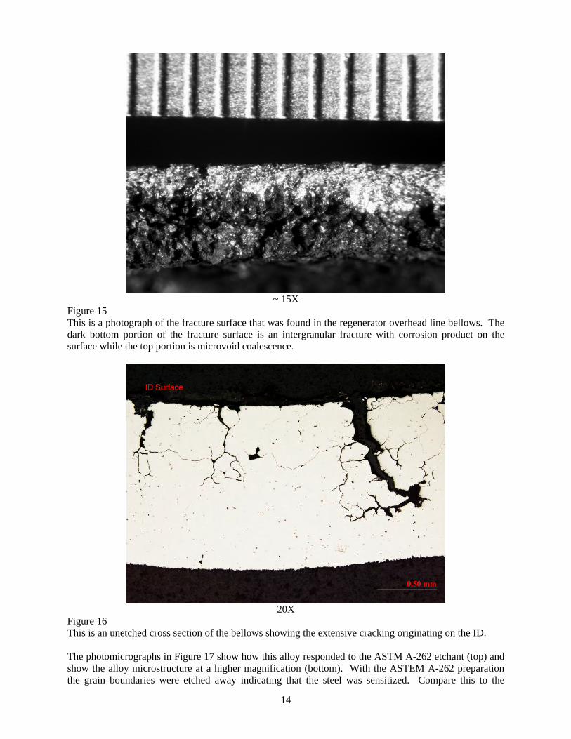
Figure 14 This is a photograph of cracks found on one of the regenerator overhead system bellows. The cracks are longer and more branched on the ID of the bellows. The expansion bellows design in the regenerator overhead system included a steam purge to keep the process side of the bellows from accumulating catalyst. However, the flow wasn’t sufficient to effectively prevent build-up, and as a result of the catalyst accumulation, the bellows would tend to operate at lower than expected temperatures. Prior to the build-up the bellows would be hot enough to sensitize the Incoloy 800, but later after catalyst accumulated, it could have gotten cool enough to cause dew point corrosion. However, if that was occurring, the failure would have occurred while the unit was operating. The fact that the failure occurred shortly after the FCCU shut down and restarted indicates that the corrosion occurred during the shut down instead of while the unit was operating. Figure 15 is a photograph of the fracture surface. The ID is located at the bottom in this photograph. The fracture is black toward the ID and bright toward the OD. The fracture also has a blocky appearance toward the ID and there are no visible characteristic toward the OD. This is an intergranular fracture on the ID side and microvoid coalescence fracture toward the OD. The top portion of this fracture occurred in the laboratory when this sample was bent. Figure 16 shows the cross section of the bellows. There were cracks everywhere originating on the ID. The photograph shows that while most of the bellows cross section was corroding, there was remaining stainless steel on the OD side that had not been damaged. However, the remaining good bellows wall was very thin and could easily fail due to a pressure surge or some other process upset.
14
~ 15X
Figure 15 This is a photograph of the fracture surface that was found in the regenerator overhead line bellows. The dark bottom portion of the fracture surface is an intergranular fracture with corrosion product on the surface while the top portion is microvoid coalescence.
20X
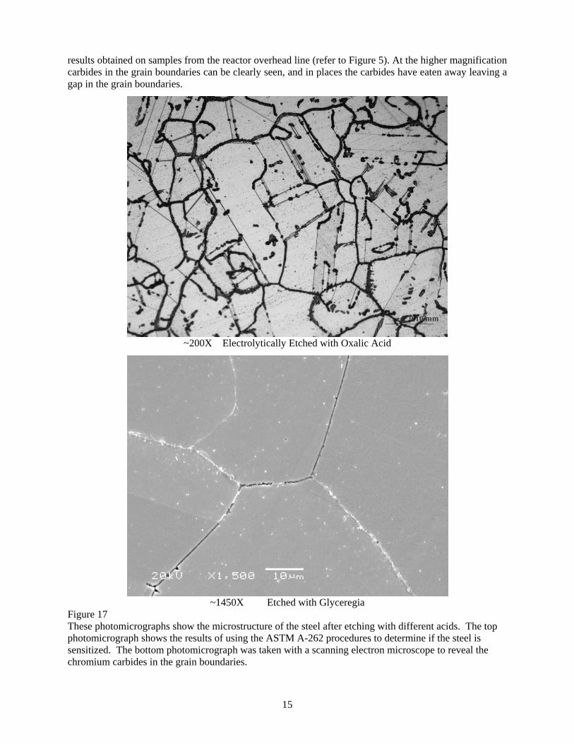
Figure 16 This is an unetched cross section of the bellows showing the extensive cracking originating on the ID. The photomicrographs in Figure 17 show how this alloy responded to the ASTM A-262 etchant (top) and show the alloy microstructure at a higher magnification (bottom). With the ASTEM A-262 preparation the grain boundaries were etched away indicating that the steel was sensitized. Compare this to the
15
results obtained on samples from the reactor overhead line (refer to Figure 5). At the higher magnification carbides in the grain boundaries can be clearly seen, and in places the carbides have eaten away leaving a gap in the grain boundaries.
~200X Electrolytically Etched with Oxalic Acid
~1450X Etched with Glyceregia
Figure 17 These photomicrographs show the microstructure of the steel after etching with different acids. The top photomicrograph shows the results of using the ASTM A-262 procedures to determine if the steel is sensitized. The bottom photomicrograph was taken with a scanning electron microscope to reveal the chromium carbides in the grain boundaries.
16
Analysis of the deposits found in the regenerator overhead bellows revealed that the deposits were a mixture of oxides and sulfates. The presence of sulfates indicates that dew point corrosion had occurred and H2SO4 was the corrosive that caused the bellows to fail. What probably occurred was an interruption in the steam flow to the ID of the bellows which resulted in the bellows heating to the process temperature. That caused the bellows to be sensitized, and then all that was needed to cause failure was for the bellows to cool sufficiently for dew point corrosion to occur. The use of internal and external insulation to control the bellows metal temperature as is shown in Figure 3 would be a better approach to controlling bellows temperature than counting on steam flow to keep the temperature low. Some refineries have also installed thermocouples on expansion bellows so that the temperature can be monitored. Also neutralization approaches can be used at some refineries to prevent dew point corrosion in flue gas systems as the FCCUs cool down. One common approach to preventing dew point corrosion is to inject a small amount of ammonia into the flue gas as the FCCU cools down. 3 Conclusions These two examples of bellows failures illustrate how equipment that we think has high reliability because it is older, tried and true technology can lead to significant failures. In both examples, the designs counted on steam flow to the ID of the bellows to control the bellows temperature, and interruptions in the steam flow led to the bellows getting to higher temperatures. In one case the exposure to higher temperature led to a failure, but in the other case the bellows wasn’t hot long enough to sensitize so the cause of failure wasn’t sensitization. In both instances the failures occurred after the FCCU was shut down. This indicates that better inspection techniques are needed for expansion bellows so that potential problems are identified during a time period when repairs or bellows replacement can take place. For example, better inspection of the bellows-to-pipe welds in the reactor overhead line may have identified defects in the welds, and repairs could have been made. In the regenerator overhead line a better inspection of the ID would have identified the corrosion and cracking on the bellows ID and action could have been taken to replace the bellows during the shut down. Another common aspect of both bellows is the geometry of the bellows-to-piping attachment weld. Two approaches to improving this weld were discussed in this paper, and using either approach should improve the reliability of expansion bellows. Another improvement that should be considered is changes to the bellows metallurgy. In both of these failures the alloys used could be quickly sensitized if the bellows came to the process temperature. The sensitization curves in Figure 4 show that a bellows made of Inconel 625 would not sensitize if it is heated to the process temperature in both of these overhead systems. Inconel 625 provides better general corrosion resistance and better resistance to sensitization than 321 or 347 stainless steels. It also resists sensitization much better than Incoloy 800. In both of these systems replacement bellows were made of Inconel 625, and bellows rings were used to improve the welds in the bellows on the reactor overhead expansion joint. References:
1. Dharia, D., E et al, “Increase in light olefins production,” Hydrocarbon Processing, April 2004, pp 61-66.
2. Peihl, R.L., “Stress Corrosion Cracking by Sulfur Acids,” Proceedings of the American Petroleum Institute, Refining Division, Section 3, 1964.
3. Chandler, H., Heat Treater's Guide: Practices and Procedures for Nonferrous Alloys, ASM International, 1996, p 91.
4. “The story of the INCOLOY® alloys series, from 800 through 800H, 800HT®,” Special Alloys brochure, 2004