Embed Size (px)
Citation preview
Failure of OriginalTF Inner Leg Assembly
C Neumeyer4/10/3
0
10000
20000
30000
40000
50000
60000
70000
0 0.5 1 1.5 2
Time (sec)
Itf (amp)
110201
110200
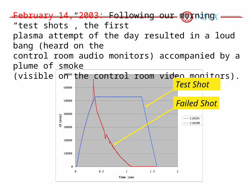
February 14, 2003: Following our morning “test shots”, the firstplasma attempt of the day resulted in a loud bang (heard on thecontrol room audio monitors) accompanied by a plume of smoke(visible on the control room video monitors).
Test Shot
Failed Shot

• Target level was 53.4kA which produces Bt=4.5kG
• Fault occurred just prior to flat top as the current passed 50kA
• Several protective devices tripped within milliseconds....
- TF power supply fault detector section overcurrent, - TF Analog Coil Protection (ACP) overcurrent,- TF Rochester Instrument System (RIS) overcurrent, - TF ground fault current relay.

Initial inspection revealed that one of the TF “flags” on the bottom end of the machine was displaced radially by about 1 inch
TF Flags
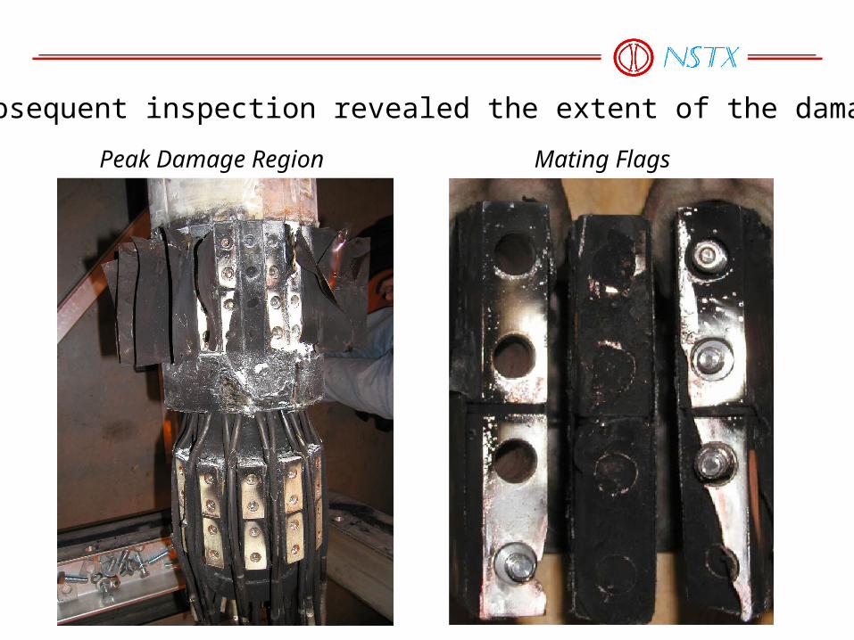
Subsequent inspection revealed the extent of the damage
Peak Damage Region Mating Flags
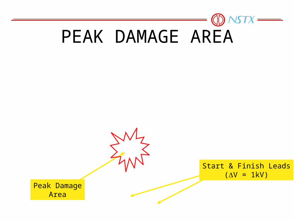
PEAK DAMAGE AREA
Peak DamageArea
Start & Finish Leads(V = 1kV)
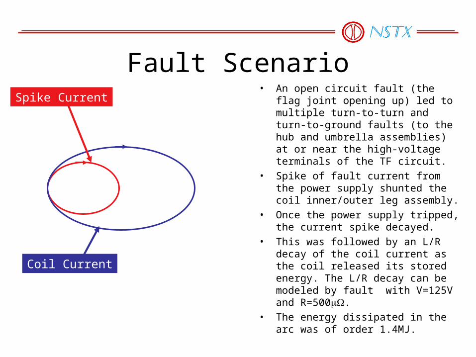
Fault Scenario• An open circuit fault (the flag joint
opening up) led to multiple turn-to-turn and turn-to-ground faults (to the hub and umbrella assemblies) at or near the high-voltage terminals of the TF circuit.
• Spike of fault current from the power supply shunted the coil inner/outer leg assembly.
• Once the power supply tripped, the current spike decayed.
• This was followed by an L/R decay of the coil current as the coil released its stored energy. The L/R decay can be modeled by fault with V=125V and R=500.
• The energy dissipated in the arc was of order 1.4MJ.
Spike Current
Coil Current
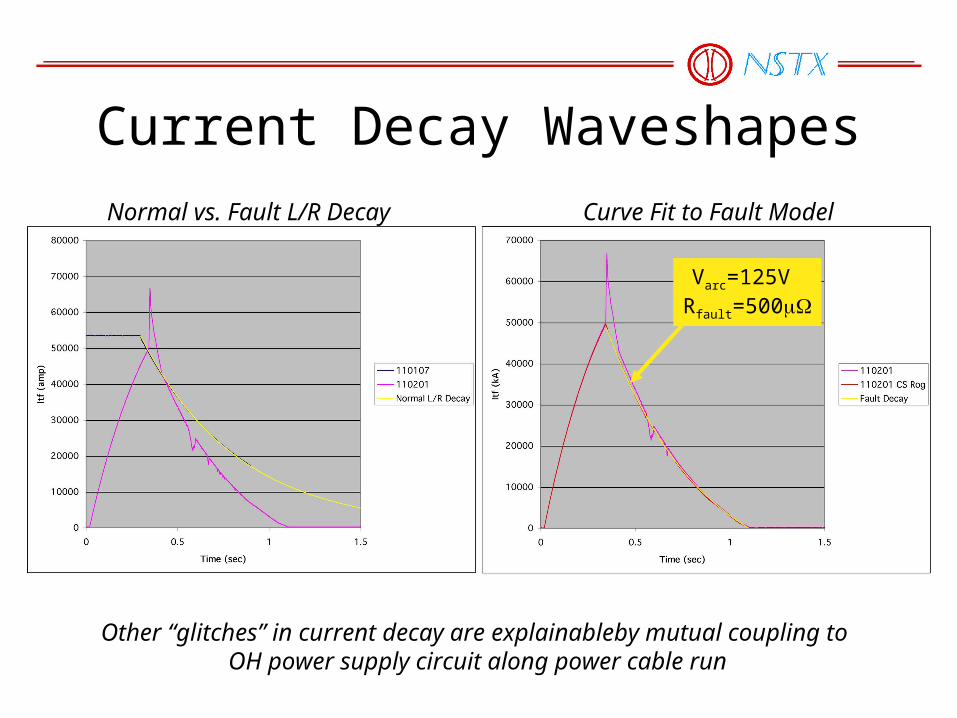
Current Decay Waveshapes
Varc=125V Rfault=500
Normal vs. Fault L/R Decay Curve Fit to Fault Model
Other “glitches” in current decay are explainableby mutual coupling to OH power supply circuit along power cable run
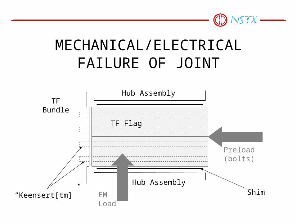
MECHANICAL/ELECTRICAL FAILURE OF JOINT
TF Flag
Hub Assembly
Hub Assembly
TFBundle
“Keensert[tm]” Shim
Preload(bolts)
EMLoad

HISTORY OF TF OPERATIONS• Approx. 7200 Shots mainly at 3kG, 4.5kG• Limited number at 6kG
3kG
4.5kG 6.0kG
FAULT
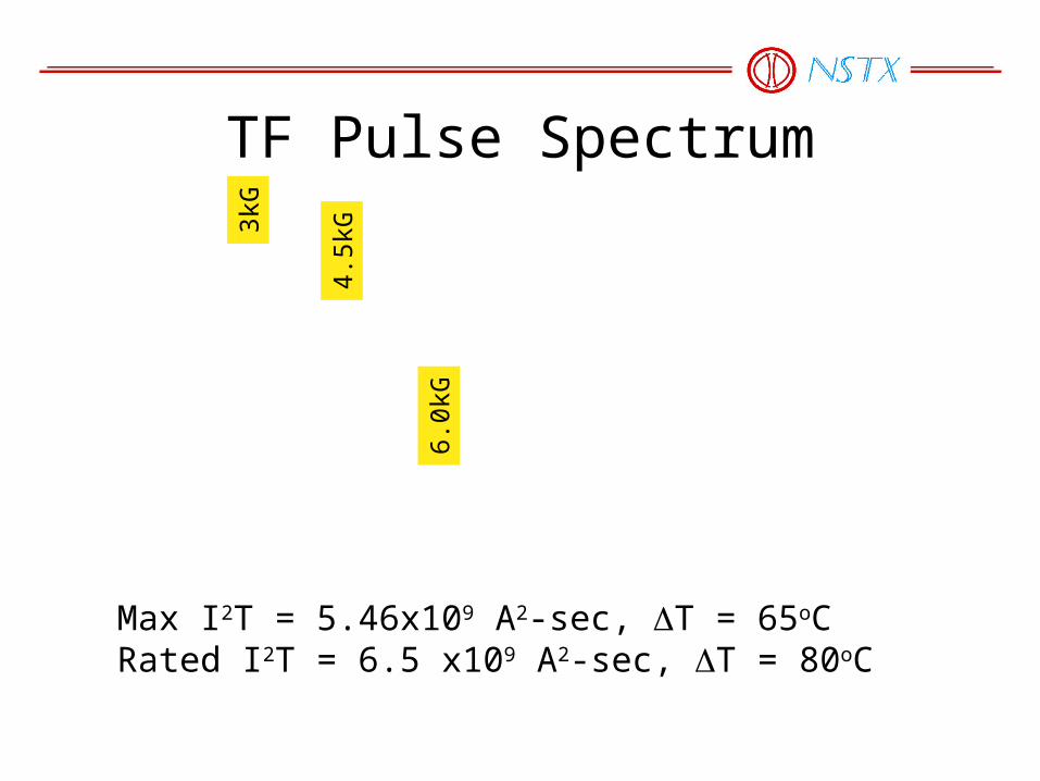
TF Pulse Spectrum
Max I2T = 5.46x10⁹ A2-sec, T = 65oCRated I2T = 6.5 x10⁹ A2-sec, T = 80oC
3kG
4.5k
G
6.0k
G

PRECURSORSEvidence of a problem surfaced after ‘02 run period
Also, loose bolts and broken inserts were discovered

RESPONSE TO PRECURSORS• Corrected Various Defects
–Resurfaced non-planar flag faces and chamfered bolt holes (bottom)
–Improved bolt washers and bolt retention (top and bottom),
–Retorqued bolts (top and bottom) and replaced 4 “keenserts” with “tap-lok” inserts (bottom),
–Replaced G-10 flag shims with inflatable epoxy shim design (top and bottom)
• Initiated more detailed FEA• Returned to 4.5kG limit• Initiated more regular inspections
Too Little, Too LateShim
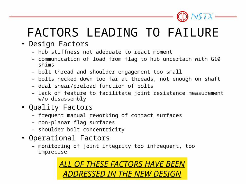
FACTORS LEADING TO FAILURE• Design Factors
– hub stiffness not adequate to react moment– communication of load from flag to hub uncertain with G10 shims – bolt thread and shoulder engagement too small– bolts necked down too far at threads, not enough on shaft– dual shear/preload function of bolts– lack of feature to facilitate joint resistance measurement w/o disassembly
• Quality Factors– frequent manual reworking of contact surfaces– non-planar flag surfaces– shoulder bolt concentricity
• Operational Factors– monitoring of joint integrity too infrequent, too imprecise
ALL OF THESE FACTORS HAVE BEENADDRESSED IN THE NEW DESIGN