Embed Size (px)
Citation preview

Failure Investigation of an Intra-Manifold Explosion in a Horizontally-Mounted 870 lbf Reaction Control Thruster
Joseph G. Durning III1 and Shayne C. Westover2
NASA Johnson Space Center, Houston, TX, 77058
and
Darren M. Cone3
NASA White Sands Test Facility, Las Cruces, NM, 88012
In June 2010, an 870 lbf Space Shuttle Orbiter Reaction Control System Primary Thruster experienced an unintended shutdown during a test being performed at the NASA White Sands Test Facility. Subsequent removal and inspection of the thruster revealed permanent deformation and misalignment of the thruster valve mounting plate. Destructive evaluation determined that after three nominal firing sequences, the thruster had experienced an energetic event within the fuel (monomethylhydrazine) manifold at the start of the fourth firing sequence.
The current understanding of the phenomenon of intra-manifold explosions in hypergolic bipropellant thrusters is documented in literature where it is colloquially referred to as a ZOT4
Converse to the typical ZOT failure mechanism, the failure of this particular thruster was determined to be the result of liquid oxidizer being present within the fuel manifold. Whereas the root cause of the failure was a leaking oxidizer valve, there were contributing factors that were characteristic of a typical ZOT reaction including: ambient pressure, horizontal thruster
. The typical ZOT scenario involves operation of a thruster in a gravitational field with environmental pressures above the triple point pressure of the propellants. Post-firing, when the thruster valves are commanded closed, there remains a residual quantity of propellant in both the fuel and oxidizer (nitrogen tetroxide) injector manifolds known as the “dribble volume”. In an ambient ground test configuration, these propellant volumes will drain from the injector manifolds but are impeded by the local atmospheric pressure. The evacuation of propellants from the thruster injector manifolds relies on the fluids vapor pressure to expel the liquid. The higher vapor pressure oxidizer will evacuate from the manifold before the lower vapor pressure fuel. The localized cooling resulting from the oxidizer boiling during manifold draining can result in fuel vapor migration and condensation in the oxidizer passage. The liquid fuel will then react with the oxidizer that enters the manifold during the next firing and may produce a localized high pressure reaction or explosion within the confines of the oxidizer injector manifold. The typical ZOT scenario was considered during this failure investigation, but was ultimately ruled out as a cause of the explosion.
1 Engineer, Propulsions Systems Branch, 2101 NASA Parkway, Houston, TX 77058/EP4. 2 Engineer, Propulsions Systems Branch, 2101 NASA Parkway, Houston, TX 77058/EP4. 3 Engineer, Laboratories Office, PO Box 20, Las Cruces, NM 88004/RF. 4 The onomatopoeia “ZOT”, although capitalized, is not definable as an acronym. Lore within the thruster community reveals it is the sound made by The Anteater, from the comic strip B.C., as it eats ants. Its relationship to the thruster phenomena remains unreported.

configuration, and a gravitational field. Additional contributors to the failure were identified that were not previously associated with a ZOT event, including local temperature conditions and sufficient leakage time to allow for propellant accumulation. In conjunction, these factors established conditions that allowed liquid oxidizer to pool in the combustion chamber after the last nominal thruster firing. As the volume of liquid oxidizer in the chamber steadily increased, migration occurred through the injector and boundary layer cooling holes into the fuel manifold. Upon initiation of the subsequent thruster firing, the in-rushing fuel reacted with the liquid oxidizer causing an explosion and pressure increase sufficient to induce substantial cracking and permanent deformation in the injector.
The telemetry data collected during the test sequence was analyzed during the failure investigation and was used to develop the sequence of events leading to the thruster failure. The temperature and pressure data corroborate the root cause, showing an overall thruster temperature decrease due to the oxidizer leak. The short dwell times between the first, second, and third pulses showed minor effects on the thruster performance while the much longer dwell time between the third and fourth pulse had a much larger effect on the thruster performance.
Figure 1 presents the thruster chamber pressure and the facility oxidizer and fuel manifold pressures during the explosive event. The “Chamber Pressure” measurement represents the pressure within the combustion chamber of the thruster as a result of the hypergolic propellant reaction. The “Fuel Manifold” and “Oxidizer Manifold” measurements represent the respective propellant fluid pressures in the distribution lines immediately upstream of the propellant isolation valves located on the thruster. The chamber pressure measurement is taken downstream of the thruster injector face while the fuel and oxidizer manifold pressure measurements are taken upstream of the thruster injector face. The thruster injector face provides a pressure boundary between the chamber and the propellant manifolds such that dynamic response of the system can be identified by interpreting the propellant pressure and chamber pressure responses.
Figure 1. Pressure Data Observed During Thruster L1L Failure.

By comparing the thruster chamber pressure and the facility oxidizer and fuel manifold pressures during the explosive event, it was clear that the energetic event occurred within the fuel manifold as evidenced by the significantly higher pressure spike. The oxidizer pressure does not appear anomalous, and the resultant chamber pressure is unusually low. Had the explosive event occurred within the thruster chamber, the chamber pressure measurement would have indicated the rapid increase. Likewise, the oxidizer manifold shows no indication of higher than expected pressure at startup which would be characteristic of a typical ZOT event.
Extensive non-destructive and destructive evaluation of the thruster was performed to characterize the failure mechanism. Detailed maps of the damaged regions of the injector were developed, with scanning electron microscopy and metallography performed to determine the individual modes of fracture within each specific region of damage. It was determined that all of the fractures observed in the thruster injector were the result of a single rapid overload event. All materials of construction were determined to meet specification requirements, and no evidence of fatigue, intergranular cracking or other subcritical cracking mechanisms were found that would contribute to the failure.
This paper documents the failure analysis and lessons learned from this unique and previously undocumented failure mechanism.

American Institute of Aeronautics and Astronautics
1
Failure Investigation of an Intra-Manifold Explosion in a Horizontally-Mounted 870 lbf Reaction Control Thruster
Joseph G. Durning III1 and Shayne C. Westover2
NASA Johnson Space Center, Houston, TX, 77058
and
Darren M. Cone3
NASA White Sands Test Facility, Las Cruces, NM, 88012
A ground test of an 870 lbf Shuttle reaction control thruster experienced and unplanned failure. Inspection of the thruster found significant deformation of the fuel manifold closure with obvious cracking. Further investigation determined than an explosive event occurred within the fuel manifold. The explosion occurred because of liquid oxidizer present in the fuel manifold. The oxidizer in the fuel manifold failure mechanism was previous undocumented and in contrast to the typical intra-manifold explosion mechanism where fuel is present in the oxidizer manifold.
Nomenclature lbf = pounds force
I. Introduction The Space Shuttle Reaction Control System (RCS) is a pressure fed hypergolic propulsion system using
monomethylhydrazine (MMH) as the fuel and nitrogen tetroxide (NTO) as the oxidizer. There are three RCS on each Shuttle, one in the forward module and one in each of the two Orbiter Maneuvering System (OMS) pods at the aft. The Forward RCS (FRCS) contains 14 Primary and 2 Vernier thrusters. The two Aft RCS (ARCS) systems each contain 12 Primary and 2 Vernier thrusters. The Primary thrusters are rated at 870 lbf vacuum thrust and the Vernier thrusters are rated at 24 lbf vacuum thrust.
Ground testing of the thrusters began with system level qualification in 1979. An ARCS structural assembly was populated with a compliment of development thrusters and subjected to qualification testing. After completion of the qualification test, a Fleet Leader program was implemented in 1989 at the White Sands Test Facility (WSTF) in Las Cruces New Mexico. The objective of the Fleet Leader program was to provide the shuttle program with a high fidelity ground test article for hot-fire and offline system and component tests. This was accomplished by performing Mission Duty Cycle (MDC) firings to maintain approximately a 35 percent equivalent mission lead over the oldest flight system. Typical MDC tests included propellant loading, propellant conditioning, flight representative profile thruster firings, post-fire inspection and evaluation, and component and system functional checkouts.
1
As the end of the shuttle program grew closer, it was no longer necessary to complete MDC firings to extend the lead over the Shuttle fleet. However, in order to support potential special test requests, the ARCS test article was kept in a ready state with regular skills retention hot fire tests performed. The skills retention tests were intended to verify the test article and test stand electrical, controls, computer, data acquisition and mechanical systems were ready to perform testing. The hot fires also assured personnel were adequately familiar with the test procedures in the event a special test would be required.
1 Engineer, Propulsions Systems Branch, 2101 NASA Parkway, Houston, TX 77058/EP4, AIAA Member. 2 Engineer, Propulsions Systems Branch, 2101 NASA Parkway, Houston, TX 77058/EP4. 3 Engineer, Laboratories Office, PO Box 20, Las Cruces, NM 88004/RF.

American Institute of Aeronautics and Astronautics
2
During a RCS skills retention test conducted in June 2010 at the NASA White Sands Test Facility, an 870 lbf
Primary Thruster experienced an unintended shutdown. Subsequent removal and inspection of the thruster revealed permanent deformation and misalignment of the thruster valve mounting plate. Destructive evaluation determined that after three nominal firing sequences, the thruster had experienced an energetic event within the fuel manifold at the start of the fourth firing sequence.
The current understanding of the phenomenon of intra-manifold explosions in hypergolic bipropellant thrusters is documented in literature where it is colloquially referred to as a ZOT4
. The typical ZOT scenario involves operation of a thruster in a gravitational field with environmental pressures above the triple point pressure of the propellants. Post-firing, when the thruster valves are commanded closed, there remains a residual quantity of propellant in both the fuel and oxidizer injector manifolds known as the “dribble volume”. In an ambient ground test configuration, these propellant volumes tend to drain from the injector manifolds but are impeded by the local atmospheric pressure. The evacuation of propellants from the thruster injector manifolds relies on the fluids vapor pressure to expel the liquid. The higher vapor pressure oxidizer will evacuate from the manifold before the lower vapor pressure fuel. The localized cooling resulting from the oxidizer boiling during manifold draining can result in fuel vapor migration and condensation in the oxidizer passage. The liquid fuel will then react with the oxidizer that enters the manifold during the next firing and may produce a localized high pressure reaction or explosion within the confines of the oxidizer injector manifold. The typical ZOT scenario was considered during this failure investigation, but was ultimately ruled out as a cause of the explosion.
Converse to the typical ZOT failure mechanism, the failure of this particular thruster was determined to be the result of liquid oxidizer being present within the fuel manifold. Whereas the root cause of the failure was a leaking oxidizer valve, there were contributing factors that were characteristic of a typical ZOT reaction including: ambient pressure, horizontal thruster configuration, and a gravitational field. Additional contributors to the failure were identified that were not previously associated with a ZOT event, including sufficient leakage and influenced temperature conditions. In conjunction, these factors established conditions that allowed liquid oxidizer to pool in the combustion chamber after the last nominal thruster firing.
II. Failure Investigation On June 17, 2010, the ARCS Test Stand 301 (TS301) was configured to troubleshoot an anomalous condition of
the left pod side yaw firing on manifold 1 (henceforth referred to by its position indicator, L1L) and a known good down firing thruster, L3D. Three pulses would be performed on each thruster: 0.5, 1.0, and 2.0 seconds, and the current traces for each valve would be observed. The harnesses for L1L and L3D were then to be swapped and the three pulses repeated to observe if a potential avionics problem followed the L1L thruster or stayed with the facility. This would identify where further troubleshooting needed to be performed.
Thrusters L1L and L3D were simultaneously fired with the same three pulse sequence: 0.5 seconds on, 10 seconds off, 1.0 seconds on, 10 seconds off, and 2.0 seconds on. The firings were performed nominally and no anomalies were initially observed. Prior to swapping the harnesses between thrusters L1L and L3D so they could be fired again, a visible oxidizer vapor cloud was observed indicating that oxidizer was leaking from thruster L1L. The leaking oxidizer created a condition where personnel could not approach the test article to swap the cables.
The test was halted while Engineering discussed a plan to gain access to thruster L1L. Approximately 20 minutes passed while the decision was made to fire thrusters L1L and L3D again for 2.0 seconds to correct the leaking oxidizer valve on thruster L1L. During the leak mitigation firing for L1L, the profile was terminated at approximately 0.1 seconds by the facility software sequence due to a redline violation on the L1L flange temperature. An unexpected increase in the environmental temperature near thruster L1L was observed and the L1L fuel and oxidizer injector temperatures were observed flat lined at 250°F. The decision was made to back out of test operations, make the system safe, and perform inspection of the test system.
4 The onomatopoeia “ZOT”, although capitalized, is not definable as an acronym. Lore within the thruster community reveals it is the sound made by The Anteater, from the comic strip B.C., as it eats ants. Its relationship to the thruster phenomena remains unreported.2

American Institute of Aeronautics and Astronautics
3
Upon gaining access to the test stand, thruster L1L was found to have melted and disconnected wires, charring on metal surfaces, and broken pressure transducer housing. The thruster was removed from the test stand for further evaluation and inspection.
Figure 1 shows the facility thermocouple wires that were observed to have charring on the insulation housing,
denuding of the leads, and wires disconnected from the thermal block. Figure 2 shows the white soot charring observed on some metal surfaces of the thruster and Fig. 3 shows the circumferential crack on the pressure transducer housing.
The valve standoff mounting plate, which is normally in a parallel plane to the thruster mounting flange, was
found to be significantly misaligned. The misalignment indicated that the integrity of the injector may have been compromised during the test abort. A chamber weld leak test was performed to check the integrity of the thruster injector and audible leaking was observed. The blowing leak was too large to quantify and potentially masked any smaller cracks or leaks that might have been present. Further inspection of the chamber weld via borescope revealed significant cracking in the closeout weld channel. The crack extended circumferentially for approximately 180°.
Figure 2. Charring noted on metal surfaces. (Photo ID WSTF0610E05892)
Figure 1. Charred, denuded, and disconnected wires noted on thruster L1L. (Photo ID WSTF0610E05896)

American Institute of Aeronautics and Astronautics
4
Figure 4 shows the profile of thruster L1L with the misalignment of the valve mounting plate and thruster mounting flange highlighted.
The nozzle and thruster valve mounting
plate were cut from the thruster chamber to allow for additional visual and radiographic inspection of the injector area. A visual inspection of the fuel and oxidizer standoff was performed and cracking of the injector material was noted. Radiographic inspection of the chamber was performed to identify other potential crack locations and to identify the depth and length of the material cracking. A map of all the observed injector fracture locations, shown in Fig 5., was made to aid in the formulation of a chamber sectioning plan.
Figure 5 is a color coded map of the
cracking found in the thruster during the failure investigation. Dashed black lines represent sectioning paths. Blue markings represent observed or potential cracking in the outer parent material of the thruster, external to the injector cavities. Green markings represent cracking that occurred in the closure weld of
Figure 4. Valve mounting plate misalignment relative to the thruster mounting flange. (Photo ID WSTF0610E05883)
Figure 3. Broken pressure transducer housing. (Photo ID WSTF0610E05889)
Figure 5. Annotated locations of cracks observed in thruster L1L during destructive evaluation. (Photo ID WSTF0710E07140)

American Institute of Aeronautics and Astronautics
5
the fuel cavity when the explosive event occurred and over pressurized the cavity. The red and yellow markings represent cracks that occurred in the base material between the fuel and oxidizer cavities. The material damage represented by the red and yellow cracks caused much discussion within the failure analysis team because the void created by the cracks created a fluid path between the two manifolds. Ultimately, it was determined that the cracks occurred as a result of the explosion and were not the cause of the explosion.
During the failure analysis, the chamber was carefully cut via Electric Discharge Machining (EDM) to allow for inspection of the cracked surfaces. The chamber was further sectioned into smaller pieces to provide access for fractographic inspection of the metal surfaces and for metallographic inspection of the thruster base metals. Figure 6 shows the thruster after the first EDM cut was made to bisect the thruster in the axial direction. Immediately evident are the fuel enclosure cracks and plastic deformation of the fuel enclosure. Figure 7 shows the “B” half of the thruster with further EDM sectioning to liberate a segment of the fuel enclosure. The fuel enclosure crack surfaces were then able to be analyzed.
A. Failure Analysis During the failure investigation, the
telemetry data collected during the test sequence was analyzed and was used to develop the sequence of events leading to the thruster failure. The test system appeared nominal leading up to the first pulse of the series. The first pulses of L1L and L3D were completed nominally with the chamber pressure transducer and both oxidizer and fuel manifold pressure transducers reading nominal pressures.
At the completion of the first pulse, the oxidizer valve on L1L developed a leak. Oxidizer was able to leak during the 10 seconds dwell time between pulses, accumulating in the combustion chamber. The accumulated oxidizer resulted in a hard start and slightly higher than nominal Pc response at the start of the second pulse. The higher pressure event was isolated to the combustion chamber as an elevated pressure response is seen by the chamber pressure transducer but the oxidizer and fuel manifold pressure transducers read nominal pressures.
After the second pulses, the oxidizer leaking from L1L flashed to vapor during the 10 second dwell time before the third pulse as the thruster was at elevated temperature from the thermal soak back of the two previous thruster firings. Because the oxidizer flashed to vapor and did not accumulate in the chamber, the third pulse resulted in a nominal firing as verified from nominal chamber pressure, oxidizer, and fuel pressure transducer measurements.
Because of the significant oxidizer leakage observed after the third pulses, a dwell time of greater than 20 minutes occurred before the decision was made to re-fire the thruster to attempt to stop the leak. During that extended dwell time, the oxidizer leaked into the L1L pressure chamber, overcame the heat vaporization with
Figure 7. Thruster L1L sectioned by EDM. (Photo ID WSTF0810E07402)
Figure 6. Further sectioning of thruster L1L to liberate the fuel enclosure. (Photo ID WSTF0810E07581)

American Institute of Aeronautics and Astronautics
6
thermal soak back from combustion subsided and pooled enough liquid to migrate into the fuel injector cavity. At the initiation of the fourth pulse, the inrushing fuel reacted with the oxidizer that had leaked into the fuel cavity, resulting in an explosive event. The chamber pressure indicated an initial dip in pressure followed by a slight rise but failed to ever reach a stable pressure, indicating good combustion was not achieved. The oxidizer manifold pressure appeared nominal, but the fuel manifold pressure saw an excessive increase in pressure consistent with an energetic event occurring within the fuel manifold.
The “Chamber Pressure” measurement represents the pressure within the combustion chamber of the thruster as a result of the hypergolic propellant reaction. The “Fuel Manifold” and “Oxidizer Manifold” measurements represent the respective propellant fluid pressures in the distribution lines immediately upstream of the propellant isolation valves located on the thruster. The chamber pressure measurement is taken downstream of the thruster injector face while the fuel and oxidizer manifold pressure measurements are taken upstream of the thruster injector face. The thruster injector face therefore provides a pressure boundary between the chamber and the propellant manifolds such that dynamic response of the system can be identified by interpreting the propellant pressure and chamber pressure responses. Figure 8 illustrates the notional locations of the pressure measurements with respect to the injector face.
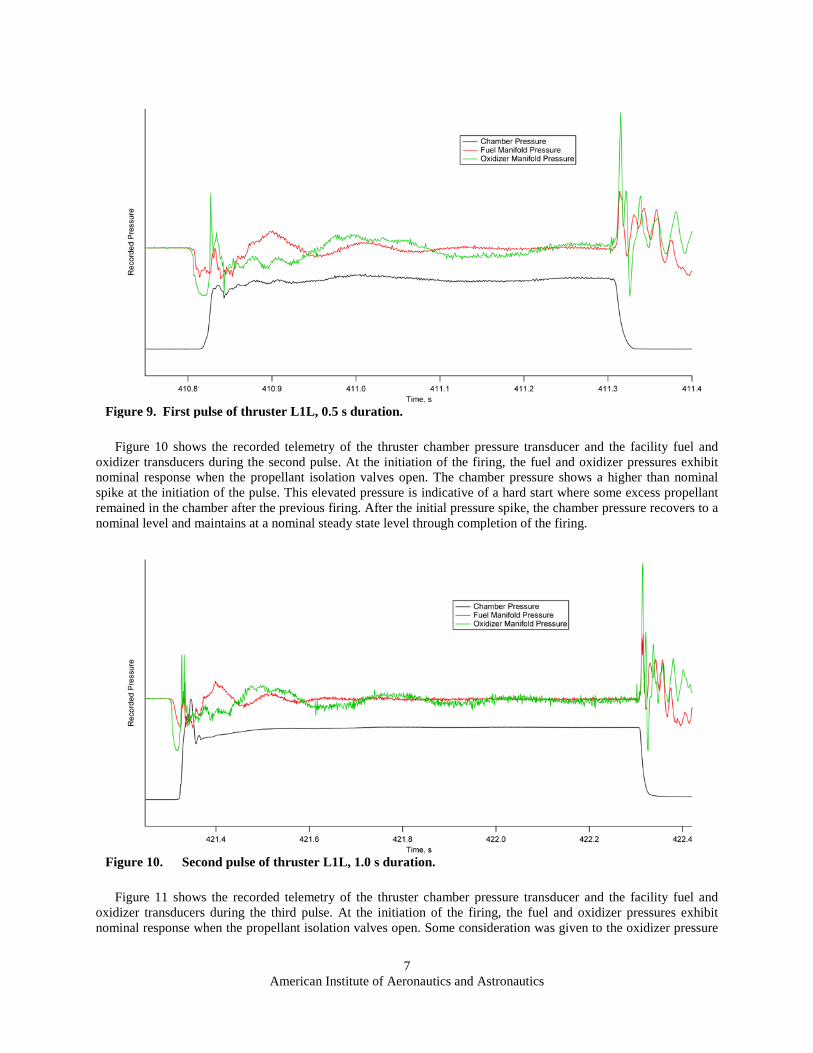
Figure 9 shows the recorded telemetry of the thruster chamber pressure transducer and the facility fuel and oxidizer transducers during the first pulse. At the initiation of the firing, the fuel and oxidizer pressures exhibit nominal response when the propellant isolation valves open. Chamber pressure response is nominal and reaches steady state levels indicative of a good thruster firing.
Figure 8. Cross sectional view of thruster L1L with pressure measurement locations annotated relative to the injector face.
American Institute of Aeronautics and Astronautics
7
Figure 10 shows the recorded telemetry of the thruster chamber pressure transducer and the facility fuel and oxidizer transducers during the second pulse. At the initiation of the firing, the fuel and oxidizer pressures exhibit nominal response when the propellant isolation valves open. The chamber pressure shows a higher than nominal spike at the initiation of the pulse. This elevated pressure is indicative of a hard start where some excess propellant remained in the chamber after the previous firing. After the initial pressure spike, the chamber pressure recovers to a nominal level and maintains at a nominal steady state level through completion of the firing.
Figure 11 shows the recorded telemetry of the thruster chamber pressure transducer and the facility fuel and oxidizer transducers during the third pulse. At the initiation of the firing, the fuel and oxidizer pressures exhibit nominal response when the propellant isolation valves open. Some consideration was given to the oxidizer pressure
Figure 10. Second pulse of thruster L1L, 1.0 s duration.
Figure 9. First pulse of thruster L1L, 0.5 s duration.

American Institute of Aeronautics and Astronautics
8
spike at the initiation of the pulse but after reviewing historical telemetry data, the pressure was determined to be in family. Chamber pressure response is nominal and reaches steady state levels indicative of a good thruster firing.
Figure 12 shows the recorded telemetry of the thruster chamber pressure transducer and the facility fuel and oxidizer transducers during the explosive failure event. At the initiation of the firing, the fuel and oxidizer pressures initially exhibit nominal response when the propellant isolation valves open. However, the fuel pressure then experiences an uncharacteristic spike corresponding to a drop-off of the chamber pressure. From that time onward, the chamber pressure fails to reach a nominal level, becomes erratic, and finally declines when the facility abort halted the firing profile. Ringing is seen in the fuel and oxidizer supply pressures from the explosive shock and resulting water hammer through the system.
Figure 12. Fourth pulse of thruster L1L; facility abort condition at approximately 0.1 s.
Figure 11. Third pulse of thruster L1L, 2.0 s duration.
American Institute of Aeronautics and Astronautics
9
By comparing the thruster chamber pressure and the facility oxidizer and fuel manifold pressures during the explosive event, it was clear that the energetic event occurred within the fuel manifold as evidenced by the significantly higher pressure spike. The oxidizer pressure does not appear anomalous, and the resultant chamber pressure is unusually low. Had the explosive event occurred within the thruster chamber, the chamber pressure measurement would have indicated the rapid increase. Likewise, the oxidizer manifold shows no indication of higher than expected pressure at startup which would be characteristic of a typical ZOT event.
Other failure scenarios were considered during the investigation, including: material aging, fatigue, design flaws, process escapes, corrosion, and embrittlement. A significant amount of effort was spent performing fractographic and metallographic inspection of the thruster parent materials and fracture surfaces. The results of the Materials & Process (M&P) investigation determined that the thruster crack fracture surface morphologies were consistent with a single, rapid tensile overload event. The event originated in the fuel manifold, expanding outward and causing the manifold closure to open up and outward. No evidence of preexisting cracks was found. No evidence of fatigue, intergranular cracking, or other sub-critical cracking mechanisms was found. No evidence of substandard welds or materials was found.
3
Based on the empirical evidence observed during the investigation and the M&P assessment, five specific conditions were identified that resulted in the explosive failure of the thruster. The five conditions were: the oxidizer leak, the horizontal configuration of the thruster, the 1g environment the thruster was tested at, the significant length of time the oxidizer was allowed to leak, and the thermal environment surrounding the thruster. While the leaking oxidizer valve was determined to be the root cause of the failure, the other four conditional were necessary contributors to the failure. The severity of damage to the L1L thruster unfortunately precluded identifying the reason for the leaking oxidizer valve.
B. Summary Although the absolute root cause of the leaking oxidizer valve is not known, the nominal performance of the
thruster during the previous firings and the results of the metallurgical assessment led to the determination that the oxidizer leak was a cause of the failure, not a symptom of a pre-existing failure. Historically, leaking propellant valves have been observed, sometimes caused by transient contamination on the valve sealing surface preventing the valve from fully seating when closed. In the case of the L1L failure, the valve was allowed to leak unabated for approximately 20 minutes after firing for a total of 3.5 seconds over a 23.5 second period.
While the oxidizer valve leaked, the cooling effect of the vapor phase change caused the bulk temperature of the thruster injector to reach the critical temperature of the oxidizer. The oxidizer then continued to leak from the injector but maintained a liquid state. With the thruster oriented in a horizontal position, a bowl feature is created between the injector face and the throat. Since the testing was performed in a 1g environment, the liquid oxidizer settled in the chamber bowl and as the level of the liquid increased, began to flow backward into the fuel injector passages into the fuel manifold.
After the 20 minute dwell period, the thruster was commanded to fire in an attempt to halt the oxidizer leak. When the fuel isolation valve opened and introduced liquid fuel into the manifold, a hypergolic reaction occurred, causing a rapid increase in pressure within the fuel manifold. The explosive disassembly of the thruster at the fuel manifold closure welds caused an unstable firing as evidenced by the erratic chamber pressure trace. Expectedly, there was a significant pressure increase in the fuel manifold and supply lines as observed on the facility pressure measurements. Hot gasses from the explosion were expelled outwards from the cracked injector and caused the facility flange temperature measurements to become unbounded from their installed positions.
As the facility measurements went open, the firing profile was aborted by the test software and the thruster valves were automatically commanded closed, ceasing the firing profile.
III. Conclusion The intra-manifold explosion observed during the L1L thruster firing resulted from oxidizer present in the fuel
manifold. Previous examples of intra-manifold explosions, known as ZOTS, were observed to have resulted from fuel present in the oxidizer manifold. A unique set of conditions were necessary to achieve the non-traditional ZOTS failure.

American Institute of Aeronautics and Astronautics
10
The traditional ZOTS phenomenon and this newly documented fuel manifold explosion phenomenon are
prevented during in-flight operation of the RCS thrusters by the Shuttle fault management system. In a flight configuration, thruster L1L would have been made unavailable by the Redundancy Management (RM) system when the injector temperature dropped below 65°F due to the oxidizer leak and could not have been fired. Additionally, in a reduced gravity flight environment, the leaking oxidizer would not have settled and collected in the thruster chamber; rather the liquid would tend to bead and float out of the chamber. However, the cold environment associated with flight operations would have also assisted in preventing the accumulation of oxidizer as the leaking liquid would freeze as it exited the injector, leaving the thruster as fine crystals or causing the injector to become plugged with a solid mass.
For these reasons, no actions were taken to modify the flight operations of the RCS as a result of the ground failure of thruster L1L. Sufficient flight rationale existed to continue operations as normal. The act of firing leaking thrusters in a ground based test setting was reconsideration as a result of this failure. Ultimately though, as the WSTF Fleet Leader program had ended and the end of the Shuttle program directed the decommissioning of the test stand, no actions were taken to modify the ground test procedures.
Acknowledgments The authors would like to thank the OMS/RCS and M&P Problem Resolution Team members who worked so
diligently to investigate the failed thruster.
Acronym List ARCS Aft Reaction Control System EDM Electric Discharge Machining FRCS Forward Reaction Control System M&P Materials & Process MDC Mission Duty Cycle MMH Monomethylhydrazine NTO Nitrogen Tetroxide OMS Orbiter Maneuvering System RCS Reaction Control System RM Redundancy Management TS301 Test Stand 301 WSTF White Sands Test Facility
References 1Baker, D., “Shuttle Fleet Leader OMS?RCS Testing,” NASA Lyndon B. Johnson Space Center White Sands Test Facility
[online database], URL: http://www.nasa.gov/centers/wstf/pdf/269982main_NEWshuttle_fleet_leader_oms_rcs_testing.pdf [cited 17 May 2011].
2Stechman, R., and Sumpter, D., “Development History of the Apollo Reaction Control System Engine,” AIAA/ASME/SAE/ASEE 25th Joint Propulsion Conference, AIAA 89-2388, AIAA, Reston, VA, July 1989.
3Martinez, J., and Castner, W., “Metallographic Preparation of Space Shuttle Reaction Control System Thruster Electron Beam Welds for Electron Backscatter Diffraction,” Microscopy & Microanalysis 2011 Meeting, Microscopy Society of America, Reston, VA (submitted for publication).