Embed Size (px)
Citation preview
MTL TR 91-25 AD-A240 858
FAILURE ANALYSIS OF THE APACHEMIXER PIVOT SUPPORT
VICTOR K. CHAMPAGNE, Jr., GARY WECHSLER, andMARC S. PEPIU.S. ARMY MATERIALS TECHNOLOGY LABORATORYMATERIALS TESTING AND EVALUATION BRANCH
KIRIT J. BHANSALIU.S. ARMY AVIATION SYSTEMS COMMAND, ST. LOUIS, MOENGINEERING DIRECTORATE, STRUCTURAL AND MATERIALS DIVISION
July 1991DT CS LECTESEP 3 01991
Approved for public release; distribution unlimited. 0*Original ocontalns olorplates: All DTIC repreduot-Ions will be in black and
A ivte*
91-11829
US ARMYLABORATORY COMMAND U.S. ARMY MATERIALS TECHNOLOGY LABORATORY
MA $ TECHMLOGY L AT)Y Watertown, Massachusetts 02172-0001
91 9 30 020
The findings in this report are not to be construed as an officialDepartment of the Army position, unless so designated by otherauthorized documents.
Mention; of any trade names or manufacturers in this reportashal not be construed as advertising nor as an officialindorsernent or approval of such products or companies bythe Limited States Goveirtment
DISPOSITION INSTRUCTIONS
Oestrov tnis 'soar! wfen it is no ionger r'fdod.
Oo not return it to th. originator
UNCLASSIFIEDSECURITY CLASSIFICATION OF THIS PAGE (When Data Enterd)
REPORT DOCUMENTATION PAGE READ INSTRUCTIONSBEFORE COMPLETING FORM
1. REPORT NUMBER 2. GOVT ACCESSION NO. 3. RECIPIENT'S CATALOG NUMBER
MTL TR 91-2514. 1iLE (and 5ubtdil) b. 1 YPFE 01- HEPOR I & PEHOU COVEREU
Final ReportFAILURE ANALYSIS OF THE APACHE MIXER PIVOT
SUPPORT 6. PERFORMING ORG. REPORT NUMBER
7. AUTHOR(s) 8. CON TRACT OR GRANT NUMBER(s)
Victor K. Champagne, Jr., Gary Wechsler, Marc S. Pepi, andKirit J. Bhansali*
9. PERFORMING ORGANIZATION NAME AND ADDRESS 10. PHQUHAM ELWMhN 1, PHOJ" I, I.
AREA & WORK UNIT NUMBERS
U.S. Army Materials Technology LaboratoryWatertown, Massachusetts 02172-0001SLCMT-MRM
11. CONIROLLING 01-t-ICE NAME AND AUDRESS 12. REPORT DATE
U.S. Army Laboratory Command July 19912800 Powder Mill Road 13. NUMBER Of- PAGESAdelphi, -Maryland 20783-1145 46
14. MONII HING AGENCY NAME & AUHESSL (qdift Jrom (ontroiling~fJice) 15 SECURITY CLASS. (ofJthu report)
Unclassified
15a. DECLASSIFICATION/DOWNGRADINGSCHEDULE
16. DISTRIBUTION STATEMENT (of tha Repot)
Approved for public release; distribution unlimited.
17. DISTRIBUTION STATEMENT (of the ab.tract entered in Block 20, if diffawfrom Report)
18. SUPPLEMEN7ARY NOTES
*Presently at the U.S. Army Aviation Systems Command, St. Louis, MO 63120-1798.
1 l. F.LT WUHU5 (Lontnune vnrvrse de , necc.ssaiy and .aentijy by bloc nunber)
Alloy steels Corrosion Hydrogen embrittlcmcnt4340 steels FatigueHigh strength steels Stress corrosion cracking
20. ABSTRACT (Coimmue an reverside if necessary and identfy by block number)
(SEE REVERSE SIDE)
FORM 7 ,1473 ECITION OF 1 NOV 65 IS OBSOLETEDSD 1CJAN7IC73 FC ISE D nSECURITY CLASSIFICATION OF THIS PAGE (Wh4en Data E'ntered)
SE rcUq AIFCAIOOTISPGE (W Data 'vntad)
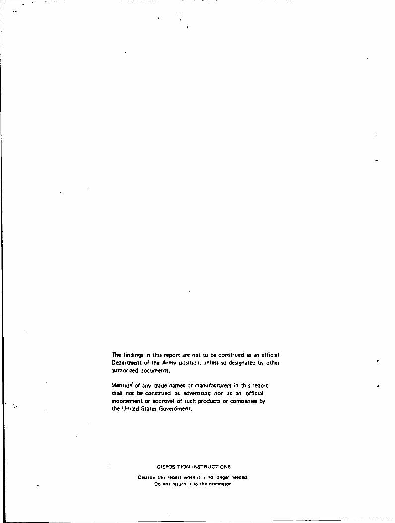
ABSTRACT
The U.S. Army Materials Technology Laboratory (MTL) conducted a failure analysisof a mixer pivot support located on the AI--64 Apache Helicopter. The component wasfound to be broken in two pieces during an inspection in Saudi Arabia while the air-craft was being utilized for Operation Desert Storm.
Visual inspection of the failed part revealed significant wear on surfaces that con-tacted the bushing and areas at the machined radius where the cadmium coating hadbeen damaged allowing corrosion pitting to occur. Light optical microscopy showed thatthe crack origin was located at the machined radius within a region that was severely pit-ted. Metallographic examination of a cross section taken through the crack initiationsite revealed cracks at the bottom of some pits running parallel to the fracture plane.The hardness, chemistry, and microstructure of the electroslag remelted (ESR) 4340 steelused to fabricate the component conformed to required specifications and no apparentmanufacturing defects were found. Electron microscopy showed that most of the frac-ture surface failed in an intergranular fashion with the exception of a shear lip zonewhich exhibited a dimpled morphology. The failure was set into action by hydrogencharging as a result of corrosion and was aggravated by the stress concentration effectsof pitting at the radius and the high notch sensitivity of the material. Energy dispersivespectroscopy (EDS) determined that deposits of sand, corrcion; and salts were foundwithin the pits. The failure mechanism was hydrogen assisted and was most likely a com-bination of stress corrosion cracking and corrosion fatigue. Recommendations have beenmade to improve the inspection criteria of tl, component in service and the material uti-lized in fabrication.
I INCLASSIEIED_SECURITY CLASSIFICATION OF THIS PAGE (When Data Entered)
CONTENTS
Page
BACKGROUND .................. .................................... 1
VISUAL INSPECTION AND LIGHT MICROSCOPY ................................ 1
METALLOGRA-P-IC EXAMINATION ....................................... 2
TENSILE TESTING .................................................... 3
HARDNESS TESTI .G .................................................. 3
CHEMICAL ANALYSIS .. ................................................ 4
ELECTRON MICROSCOPY ............................................... 5
CONCLUSIONS
C rack Initiation . . . .. . .. . .. . .. .. .. . . ... . .. . .. . . . .. .. . . . . . . .. .. . . . . 5
C orrosion Pitting .......................... ... ..... .......... ...... 6
Materials Characterization ESR 4340 Steel ................................ 6
M ode of Failure ............................................ ...... 6
Failure Scenario .. . . .. . . .. .. . .. .. . . .. . . .. . .. . . .. . . . . . . . . . . . . . .. . .. 6
Failure M echanism ................................................ 6
RECOM M ENDATIONS .................................................. 6
ACKNOW LEDGM ENTS ................................................. 7
( 'C \\ Accesion For -Co"'
INS,~r NTIS CRA&My DTIC TAB I
UrannouncedJustification
By ..... .................
Dist, ibutionI IAvailability Cooes
Avail aiidjot
Dist SpecialI-
BACKGROUND
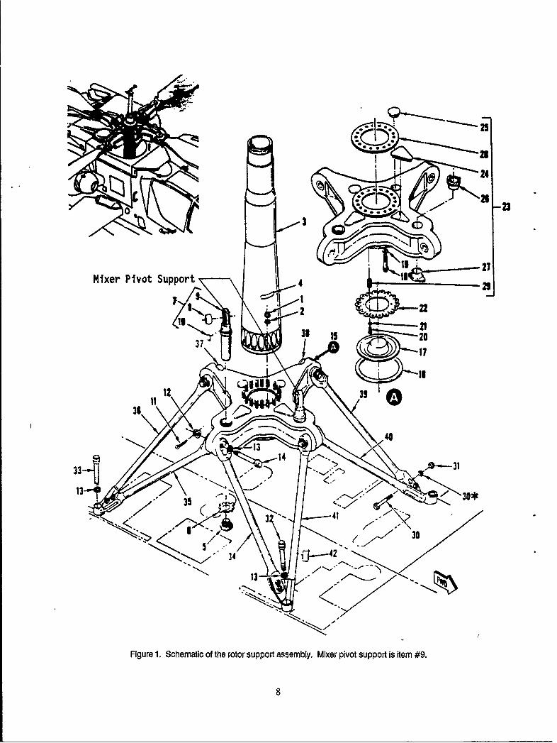
The U.S. Army Materials Technology Laboratory (MTL) was requested by the Army Avia-tion Systems Command (AVSCOM) to conduct a metallurgical examination of a mixer pivotsupport, PN 7-211160043 SN 0525, which had failed in Saudi Arabia on an AH-64 ApacheHelicopter. The mixer pivot support is a flight safety, critical component and is part of therotor support assembly as shown in Figure 1. The mixer pivot support fits through the trans-mission support. Upon inspection on January 11, 1991, the component was found to be bro-ken in half after being in service for approximately 1449 days (according to a category Ideficiency report filed by SSG Daniel Swanson). The original replacement time for the mixerpivot support, as recommended by AVSCOM, was 800 days. However, the 800 day servicelife limitation had been extended to 1440 days due to a lack of available spare parts. A sec-ond extension was granted by AVSCOM for the same reason and the component was allowedto remain in service for up to 6 months beyond 1440 days as long as no corrosion wasobserved on the surface upon inspection. The mixer pivot support was machined from 4340steel bar stock and hardened to HRC 54-57 as designated on McDonnell-Douglas engineeringdrawing number 7-211160043. The component was subsequently cadmium coated by a vacuumdeposition process.
VISUAL INSPECTION AND LIGHT OPTICAL MICROSCOPY
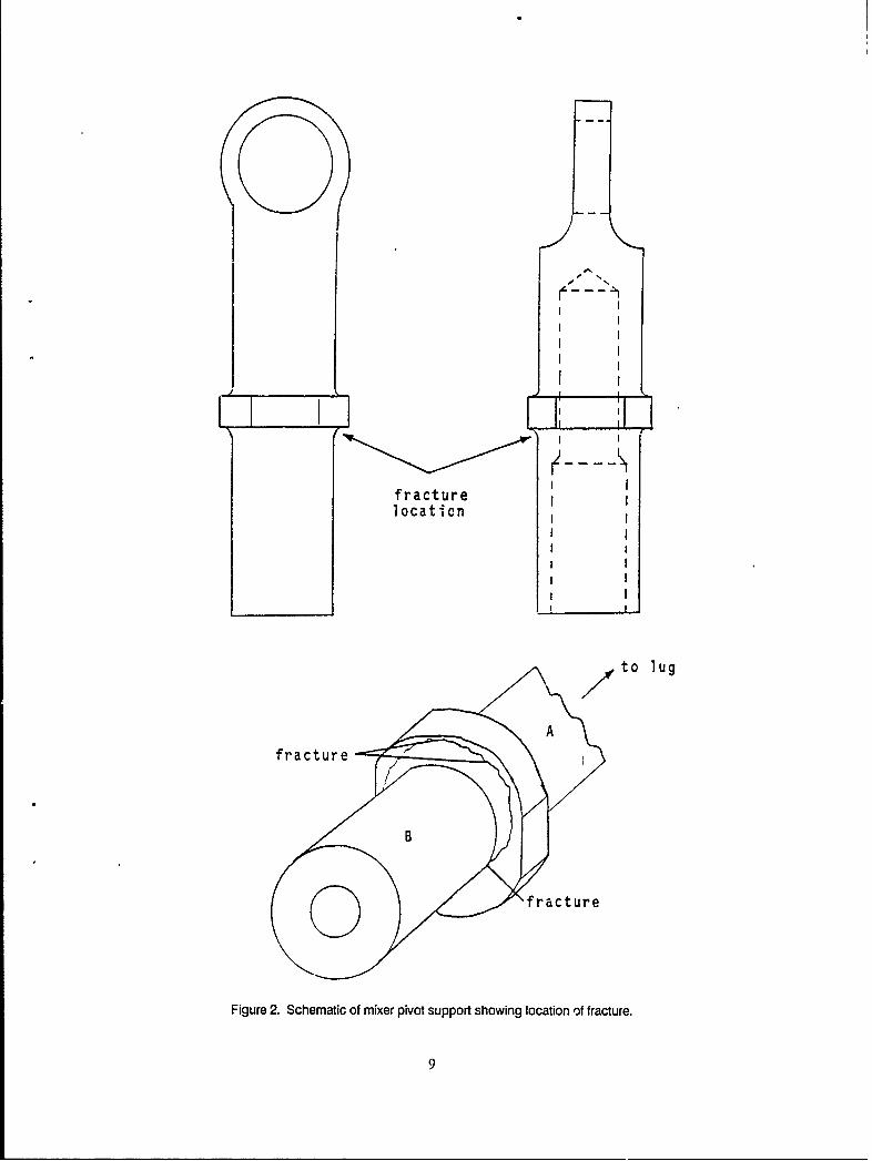
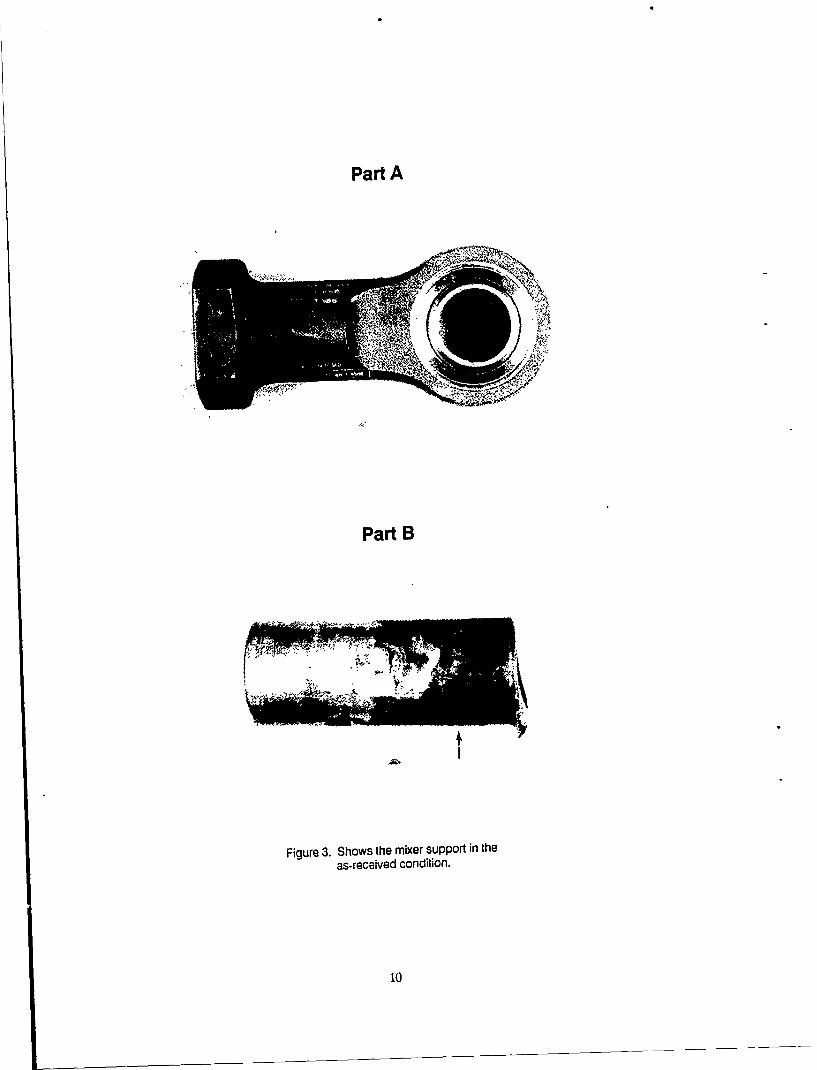
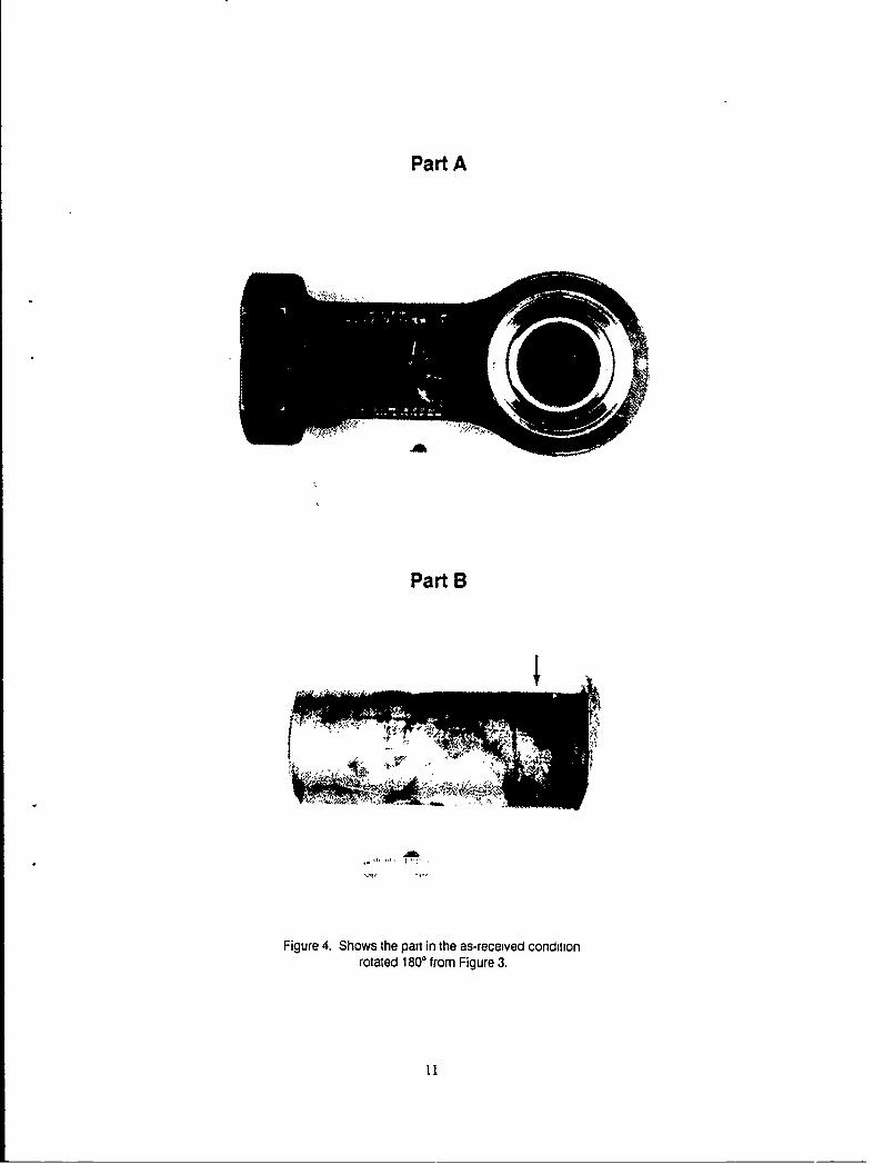
Figure 2 is a schematic of the mixer pivot support, showing the location of the failure.The failure site had been previously analyzed for stress concentrations by McDonnell-Douglasand was not identified as the most critical area. Other regions on the part were calculatedas having higher stress concentrations (Kt values). Figure 3 shows the broken component inthe as-received condition. Figure 4 was photographed after rotating the mixer pivot support1800. The upper half (Part A) of the component which contained the bearing was in rela-tively good condition, as compared to the lower half (Part B). The surface coating of Part Awas intact and the serial numbers and manufacturing identification data were easily distinguish-able. There were no obvious signs of corrosion or mechanical damage to Part A. In con-trast, however, Part B showed significant wear on surfaces that contaicted the bushing. Theseregions are characterized by dark stains (designated by the arrows) in the macrograph. Thecadmium coating appeared to have been almost entirely worn away during service and severecorrosion pitting had occurred in these areas.
Figure 5 is a graphic example of an area approximately 1.5 cm away from the major frac-ture, but within the fretted region, showing deep pits on the surface of Part B. A few ofthe pits were large and shallow and may have been formed to some extent by mechanicalvibration in addition to corrosion. Deposits of corrosion products and other debris werefound in clumps surrounding and fil!:ng a number of the pits. Figure 6 reveals a crack atthe bottom of one pit. Note the rcig;iened surface and extensive corrosion. Figure 7 showsanother pit at higher magnificatio.; In this instance, an interconnecting series of cracks wereobserved in the corrosion layer at the bottom of the pit. It was uncertain from visu.,! inspec-tion whether the cracks exterdcd into the base material. However, inetallographic examina-tion performed later in the investigation of cross sections taken through these areas, revealedevidence of cracks originating from the bot .. of pits and extending into the steel.
Figure 8A is a fractograph of Part A which was taken by exposing the fracture surfaceunder a series of various light sources which were directed onto the macroscopic features atvery acute angles. Normally, such a photograph consists of a single exposure but due to the
complexity and geometry of the fracture, four separate exposures were taken and subsequentlyblended togelher with light to obtain the contrast needed to reveal the important features ofthe fracture surface. Figure 8B is a schematic of fracture Face A which identifies the crackinitiation site and traces tl'e fracture path. The fracture plane intersected the radius at thecrack origin. The radial lines and chevron patterns indicated that the fracture proceededfrom the bottom right of the photograph (as designated by the arrow) up along both sides ofthe central hole. Where the two fractures meet at the top, a ridge is visible. This suggestedthat the fracture, indeed originated at the bottom radius, as illustrated.
Figure 9A is a fractograph of Part B which also reveals the crack origin and direction ofpropagation. The fracture face was badly smeared in many areas, as indicated by the brightspots on the photograph. This may have been caused by improper handling of the fracturedcomponent prior to examination, possibly the result of forcing both halves of the fracturefaces together. Damage may have also occurred when the component was removed from theaircraft or after it had failed. In all cases the surface smearing is attributable to a post-frac-ture incident. An important feature of the fracture, located at the very top of the photo-graph, is a shear lip region where final fracture had occurred. Both Faces A and Bcontained surfaces that were very flat-faced in appearance, displaying no signs of plasticity,which is often associated with a brittle fracture. The shear lip zone, however, showed evi-dence of ductility. The existerce of a shear lip zone served to further substantiate the loca-tion identified as the crack ofigin, since final fracture would tend to occur in an areaupposite the initiation site on this component.
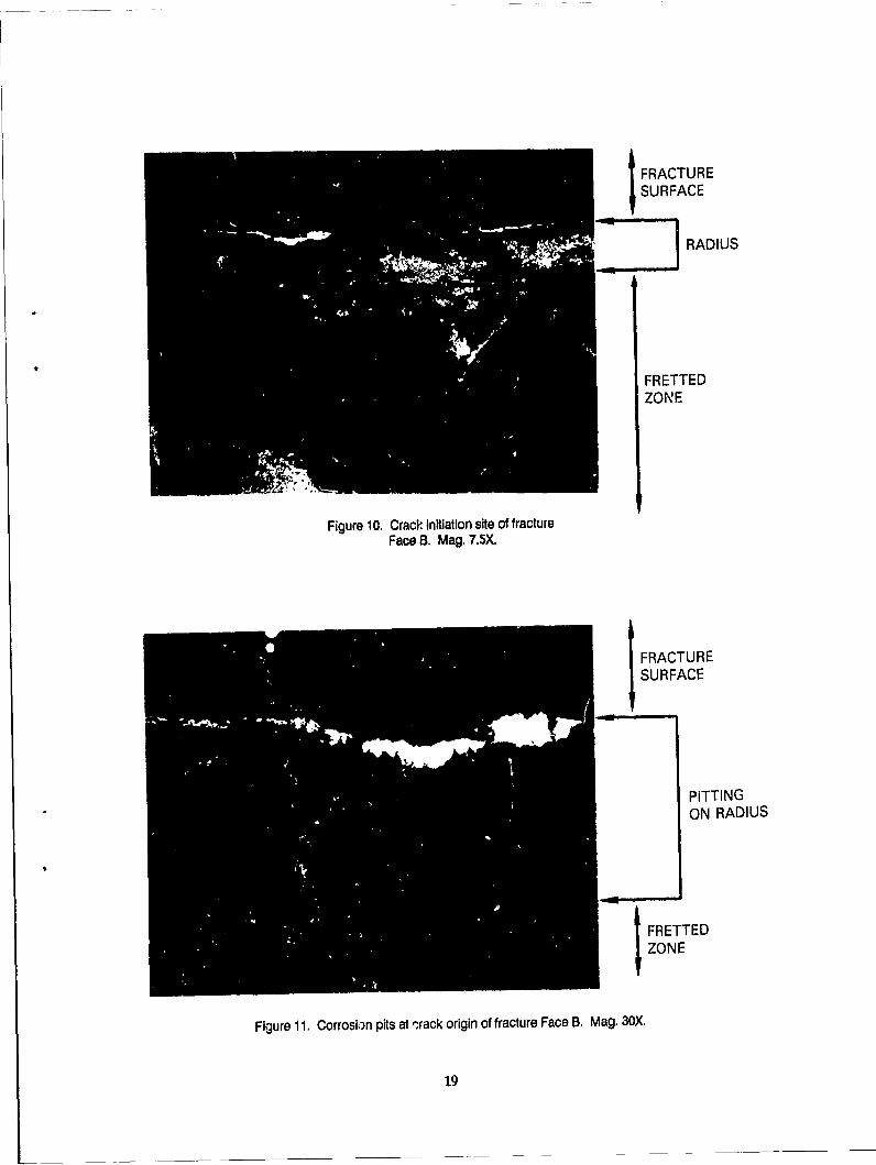
Extensive corrosion pitting was another critical feature found at the crack origin and adja-cent to the fracture plane. Figure 10 shows this corrosion near the crack initiation site andon the radius (high stress concentration area) of fracture Face B. The corrosion is locatedjust beyond the region of severe fretting, as identified in the photograph (see Figure 10).Figure 11 reveals this pitted region at higher magnification. The bright feature bordering theradius and fracture plane is smeared metal which is highly reflective. The pits were concen-trated at the crack origin and were considered to be relatively deep (as confirmed later bymetallographic examination) fur this material in the hardened condition (HRC 54-57).
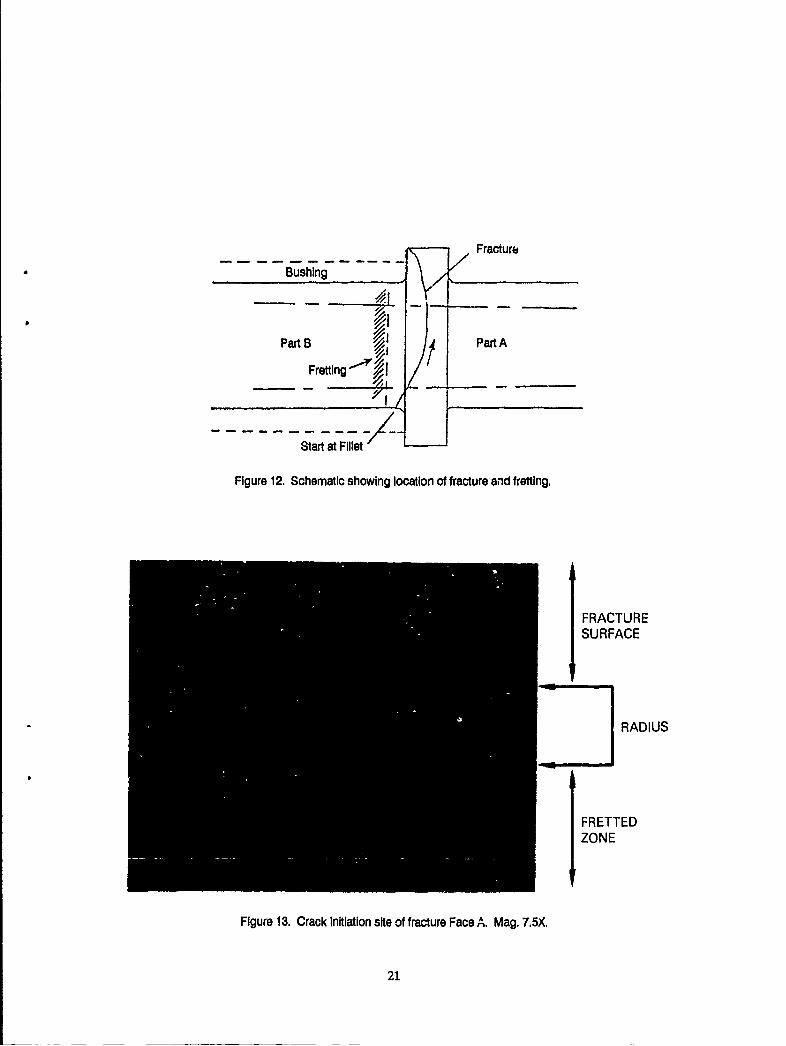
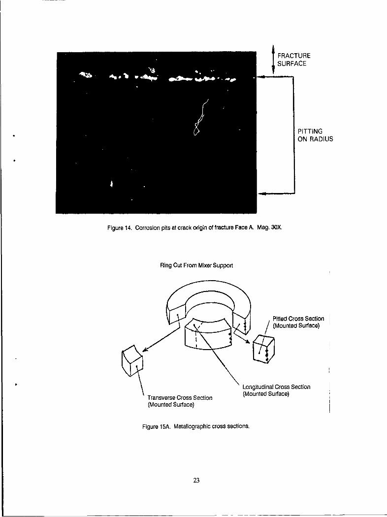
Figure 12 is a schematic which defines the area of fretting and its location relative to thefracture plane. It is important to note that the region of severe fretting was located justbelow the fracture plane and crack origin. Figure 13 is a macrograph of the crack initiationsite located on fracture Face A. Again extensive corrosion pitting had occurred in thisregion. Figure 14 shows the corrosive attack at higher magnification. The entire area hdexperienced severe attack.
METALLOGRAPHIC EXAMINATION
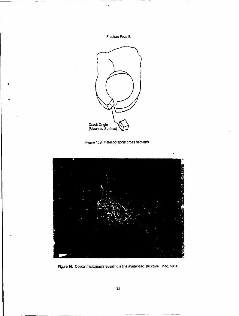
Figure 15A illustrates the areas where metallographic specimens were sectioned fromPart B of the mixer pivot support. A riog of material was taken approximately 3/4 of aninch away from the fracture face. In addition to the longitudinal and transverse specimenssectioned from the ring, a third cross section was removed which contained extensive pittingon the exterior surface. Another - oss section was taken through the crack origin of fractureFace B as shown schematically in Figure 15B. All of these specimens were utilized to charac-terize the microstructure of the material within specific areas of concern and to measure thedepth of pitting.
2
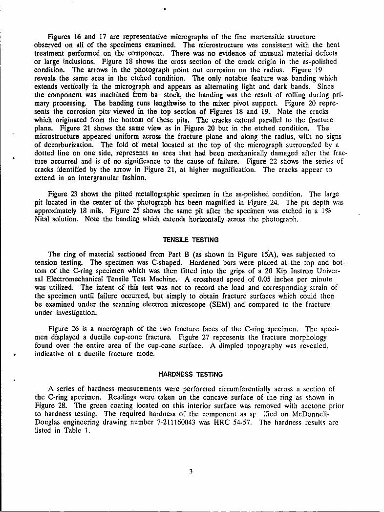
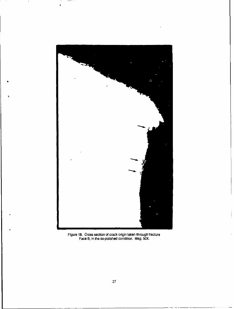
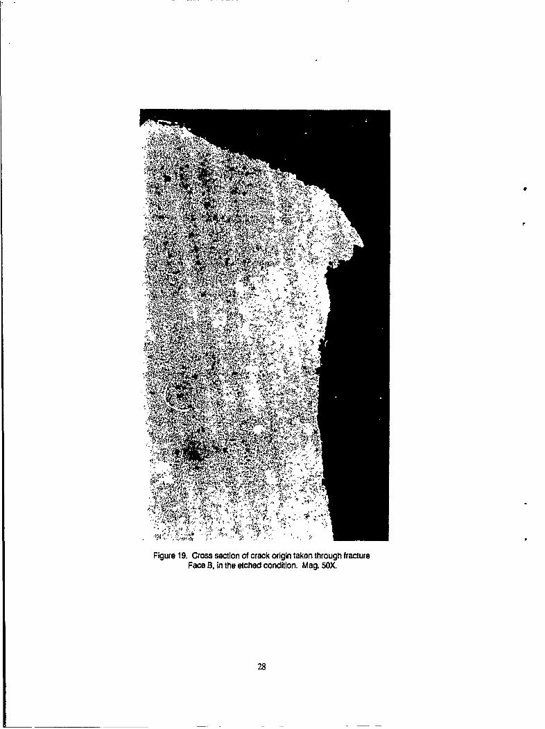
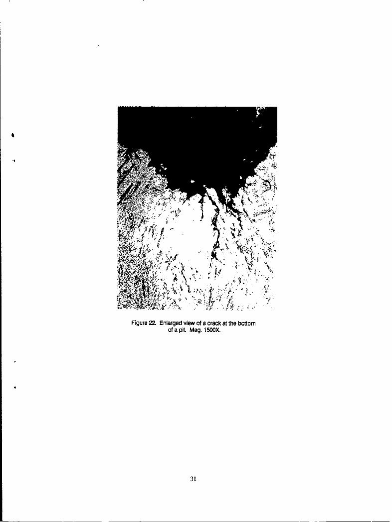
Figures 16 and 17 are representative micrographs of the fine martensitic structureobserved on all of the specimens examined. The microstructure was consistent with the heattreatment performed on the component. There was no evidence of unusual material defectsor large inclusions. Figure 18 shows the cross section of the crack origin in the as-polishedcondition. The arrows in the photograph point out corrosion on the radius. Figure 19reveals the same area in the etched condition. The only notable feature was banding whichextends vertically in the micrograph and appears as alternating light and dark bands. Sincethe component was machined from ba- stock, the banding was the result of rolling during pri-mary processing. The banding runs lengthwise to the mixer pivot support. Figure 20 repre-sents the corrosion pits- viewed in the top section of Figures 18 and 19. Note the crackswhich originated from the bottom of these pits. The cracks extend parallel to the fractureplane. Figure 21 shows the same view as in Figure 20 but in the etched condition. Themicrostructure appeared uniform across the fracture plane and along the radius, with no signsof decarburization. The fold of metal located at the top of the micrograph surrounded by adotted line on one side, represents an area that had been mechanically damaged after the frac-ture occurred and is of no significance to the cause of failure. Figure 22 shows the series ofcracks identified by the arrow in Figure 21, at higher magnification. The cracks appear toextend in an intergranular fashion.
Figure 23 shows the pitted metallographic specimen in the as-polished condition. The largepit located in the center of the photograph has been magnified in Figure 24. The pit depth wasapproximately 18 mils. Figure 25 shows the same pit after the specimen was etched in a 1%Nital solution. Note the banding which extends horizontally across the photograph.
TENSILE TESTING
The ring of material sectioned from Part B (as shown in Figure 15A), was subjected totension testing. The specimen was C-shaped. Hardened bars were placed at the top and bot-tom of the C-ring specimen which was then fitted into the grips of a 20 Kip Instron Univer-sal Electromechanical Tensile Test Machine. A crosshead speed of 0.05 inches per minutewas utilized. The intent of this test was not to record the load and corresponding strain ofthe specimen until failure occurred, but simply to obtain fracture surfaces which could thenbe examined under the scanning electron microscope (SEM) and compared to the fractureunder investigation.
Figure 26 is a macrograph of the two fracture faces of the C-ring specimen. The speci-men displayed a ductile cup-cone fracture. Figu'e 27 represents the fracture morphologyfound over the entire area of the cup-cone surface. A dimpled topography was revealed,indicative of a ductile fracture mode.
HARDNESS TESTING
A series of hardness measurements were performed circumferentially across a section ofthe C-ring specimen. Readings were taken on the concave surface of the ring as shown inFigure 28. The green coating located on this interior surface was removed with acetone priorto hardness testing. The required hardness of the component as sp ::ied on McDonnell-Douglas engineering drawing number 7-211160043 was HRC 54-57. The hardness results arelisted in Table 1.
3
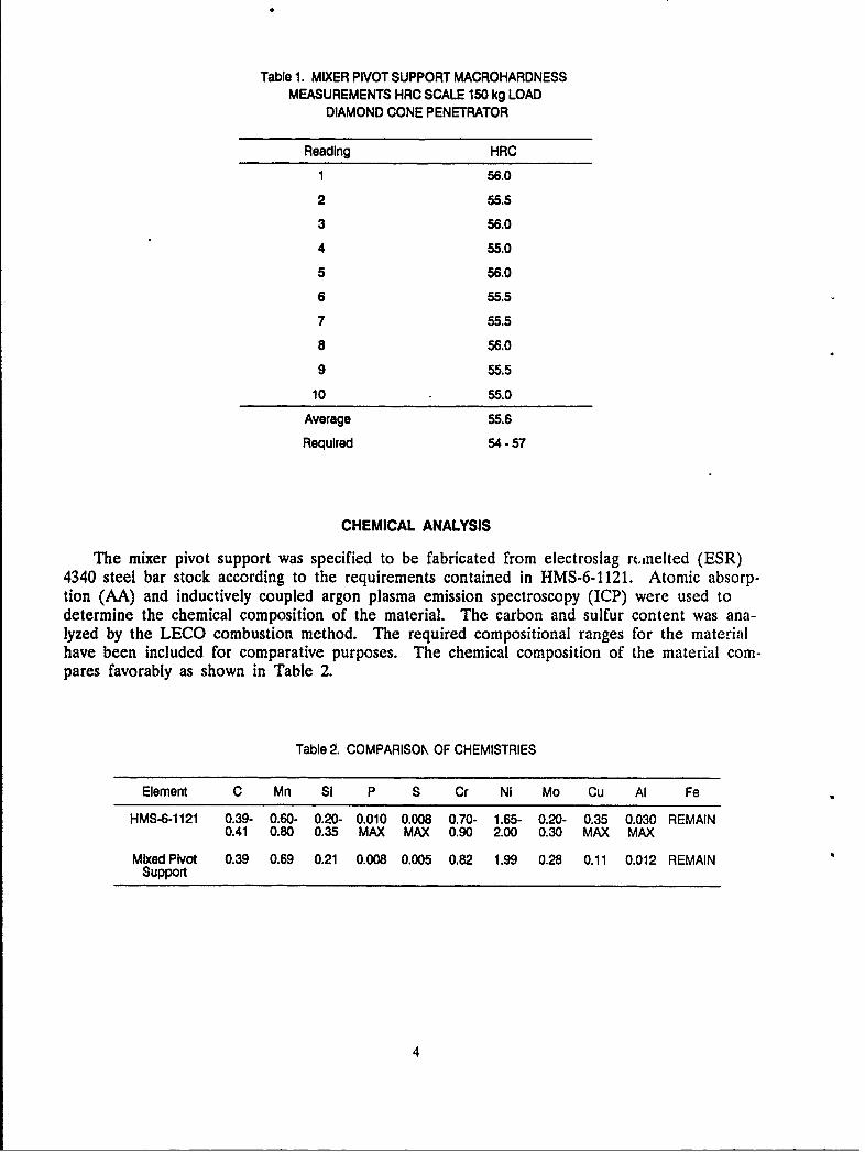
Table 1. MIXER PIVOT SUPPORT MACROHARDNESSMEASUREMENTS HRC SCALE 150 kg LOAD
DIAMOND CONE PENETRATOR
Reading HRC
1 56.0
2 55.5
3 56.0
4 55.0
5 56.0
6 55.5
7 55.5
8 56.0
9 55.5
10 55.0
Average 55.6
Required 54-57
CHEMICAL ANALYSIS
The mixer pivot support was specified to be fabricated from electroslag rcinelted (ESR)4340 steel bar stock according to the requirements contained in HMS-6-1121. Atomic absorp-tion (AA) and inductively coupled argon plasma emission spectroscopy (ICP) were used todetermine the chemical composition of the material. The carbon and sulfur content was ana-lyzed by the LECO combustion method. The required compositional ranges for the materialhave been included for comparative purposes. The chemical composition of the material com-pares favorably as shown in Table 2.
Table 2. COMPARISOK OF CHEMISTRIES
Element C Mn Si P S Cr Ni Mo Cu Al Fe
HMS-6-1121 0.39- 0.60- 0.20- 0.010 0.008 0.70- 1.65- 0.20- 0.35 0.030 REMAIN0.41 0.80 0.35 MAX MAX 0.90 2.00 0.30 MAX MAX
Mixed Pivot 0.39 0.69 0.21 0.008 0.005 0.82 1.99 0.28 0.11 0.012 REMAINSupport
4
ELECTRON MICROSCOPY
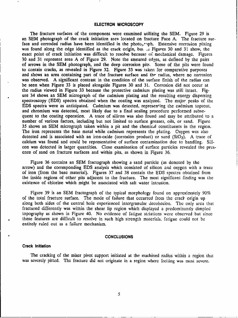
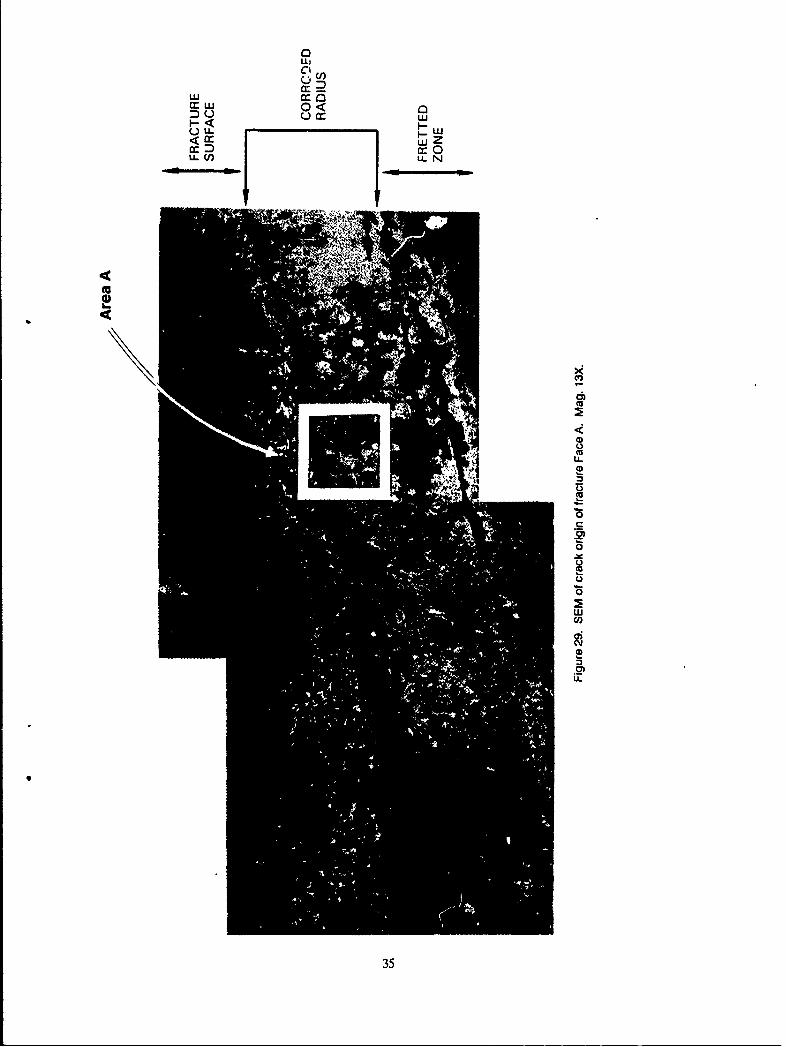
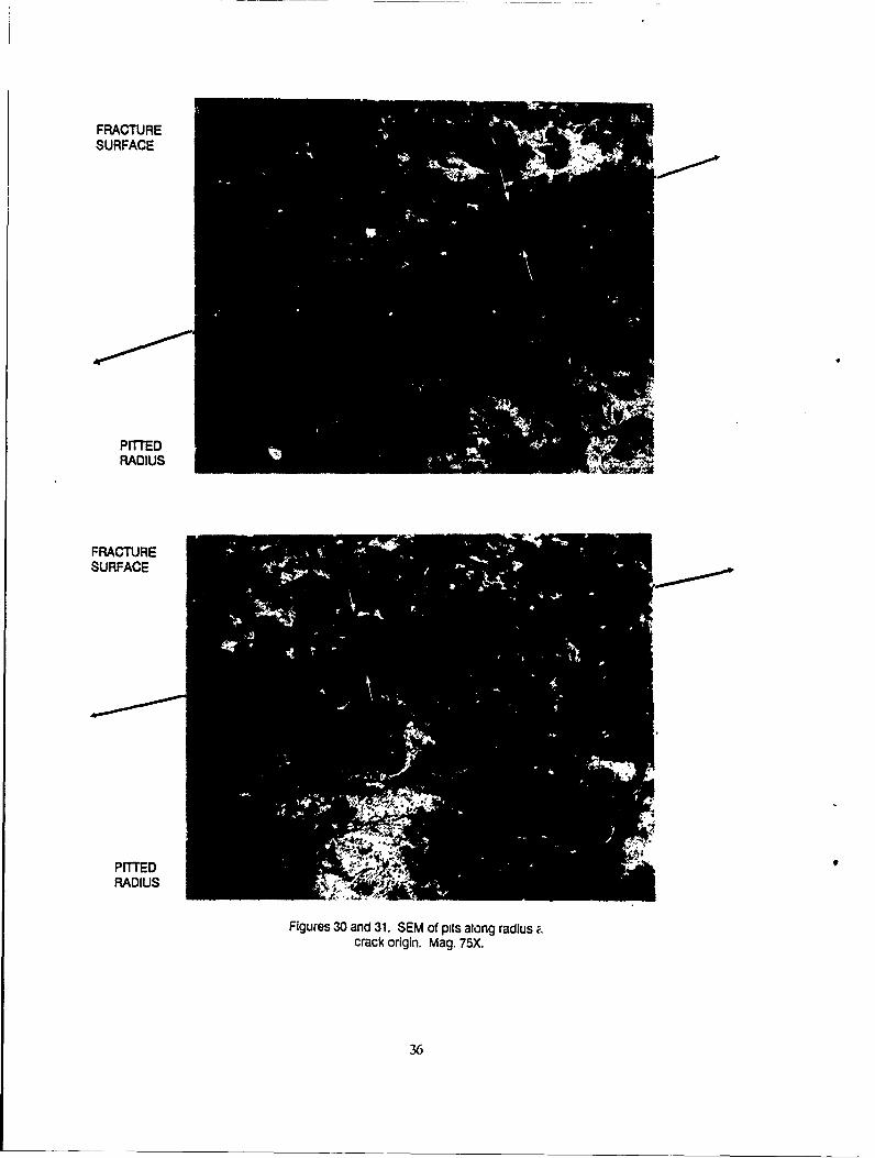
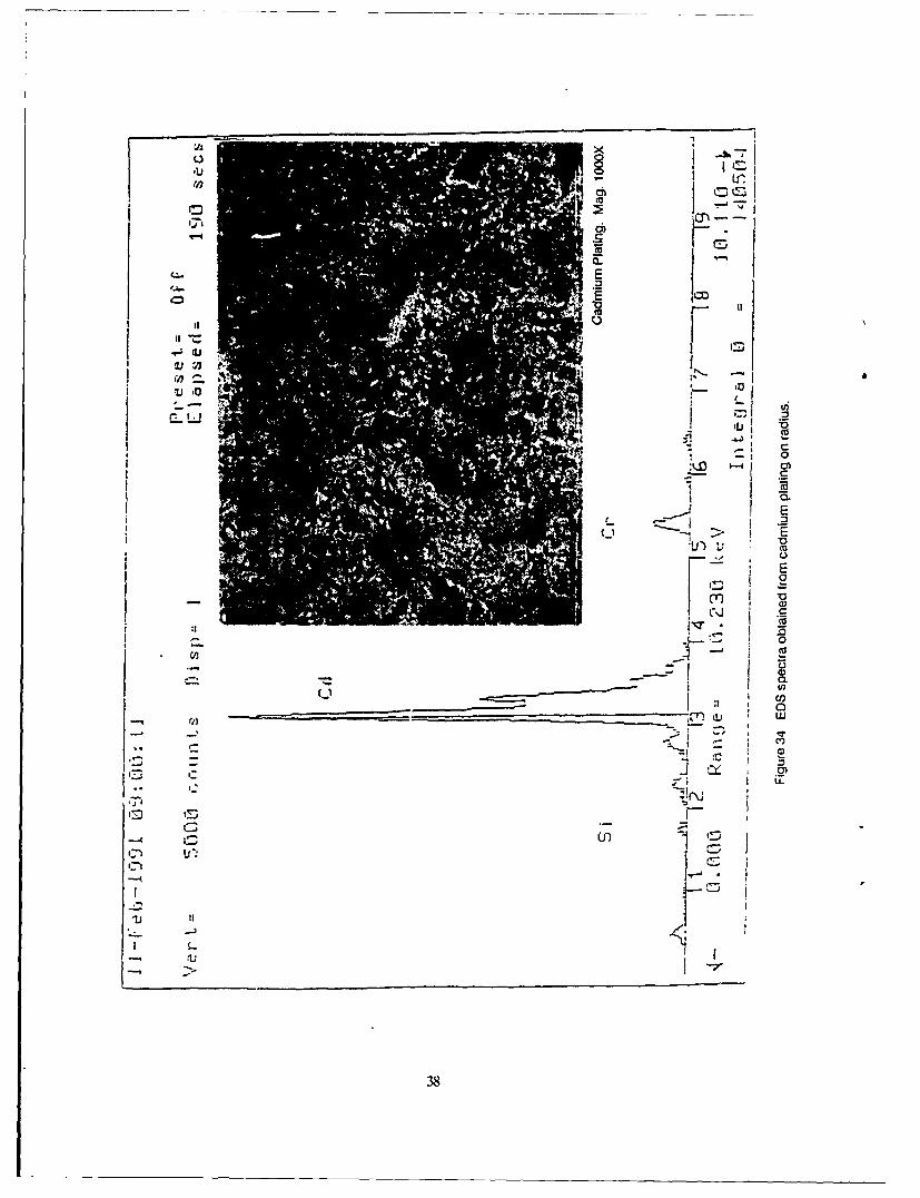
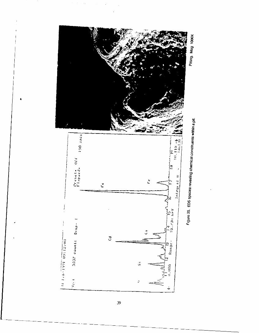
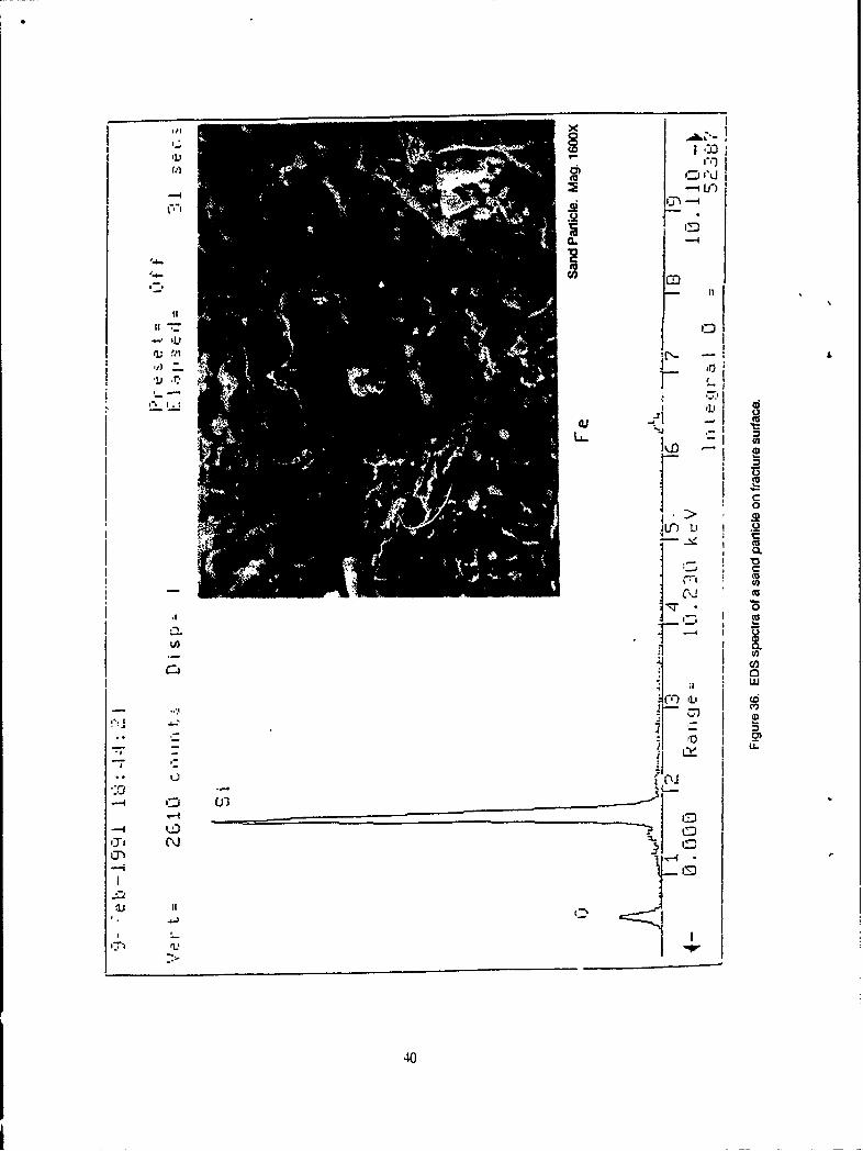
The fracture surfaces of the component were examined utilizing the SEM. Figure 29 isan SEM photograph of the crack initiation area located on fracture Face A. The fracture sur-face and corroded radius have been identified in the photo .- iph. Extensive corrosion pittingwas found along the edge identified as the crack origin, but ..zi Figures 30 and 31 show, theexact point of crack initiation was difficult to resolve because o" mechanical damage. Figures30 and 31 represent area A of Figure 29. Note the smeared edges, as defined by the pairsof arrows in the SEM photograph, and the deep corrosion pits. Some of the pits were foundto contain cracks, as revealed in Figure 32. Figure 33 was raken for comparative purposesand shows an area containing part of the fracture surface and the radius, where no corrosionwas observed. A significant contrast in the condition of the surface finish of the radius canbe seen when Figure 33 is placed alongside Figures 30 and 31. Corrosion did not occur atthe radius viewed in Figure 33 because the protective cadmium plating was still intact. Fig-ure 34 shows an SEM micrograph of the cadmium plating and the resulting energy dispersingspectroscopy (EDS) spectra obtained when the coating was analyzed. The major peaks of theEDS spectra were as anticipated. Cadmium was detected, representing the cadmium topcoat,and chromium was detected, most likely due to a final sealing procedure performed subse-quent to the coating operation. A trace of silicon was also found and may be attributed to anumber of various factors, including but not limited to surface greases, oils, or sand. Figure35 shows an SEM micrograph taken within a pit and the chemical constituents in the region.The iron represents the base metal while cadmium represents the plating. Oxygen was alsodetected and is associated with an iron-oxide (corrosion product) or sand (SiO 2). A trace ofcalcium was found and could be representative of surface contamination due to handling. Sili-con was detected in larger quantities. Close examination of surface particles revealed the prcs-ence of sand on fracture surfaces and within pits, as shown in Figure 36.
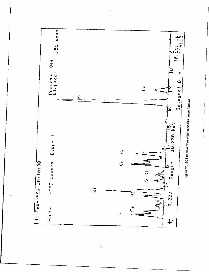
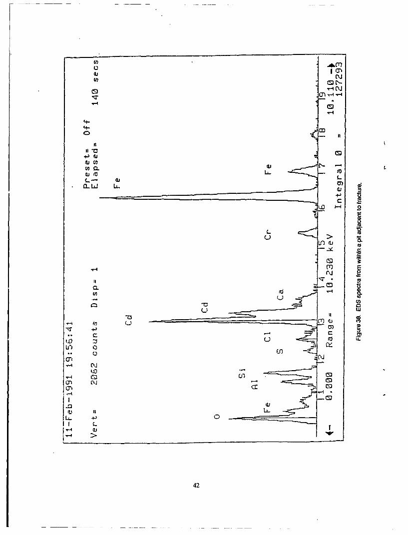
Figure 36 contains an SEM fractograph showing a sand particle (as denoted by thearrow) and the corresponding EDS analysis which consisted of silicon and oxygen with a traceof iron (from the base material). Figures 37 and 38 contain the EDS spectra obtained fromthe inside regions of other pits adjacent to the fracture. The most significant finding was theexistence of chlorine which might be associated with salt water intrusion.
Figure 39 is an SEM fractograph of the typical morphology found on approximately 90%of the total fracture surface. The mode of failure that occurred from the crack origin upalong both sides of the central hole experienced intergranular decohesion. The only area thatfractured differently was within the shear lip region which displayed a predominantly dimpledtopography as shown in Figure 40. No evidence of fatigue striations were observed but sincethese features are difficult to resolve in such high strength materials, fatigue could not beentirely ruled out as a failure mechanism.
CONCLUSIONS
Crack Initiation
The cracking of the mixer pivot support initiated at the machined radius within a region thatwas severely pitted. The fracture did not originate in a region where fretting was most severe.
5
Corrosion Pitin
Deposits of sand, corrosion, and salts were found within the pits examined. The depthsof some of the pits were as much as 18 mils. Metallographic examination of a cross sectiontaken through the crack origin revealed cracks in the bottom of some pits. These cracks ranparallel to the fracture plane.
Materials Characterization ESR 4340 Steel
The hardness, chemistry, and microstructure of the material conformed to the requiredspecifications and no apparent manufacturing defects were found on the component.
Mode of Failure
The fracture was brittle i- nature; showing little ductility, with the exception of the shearlip region. The morphology of most of the entire fracture surface (approximately 90%) wasintergranular while the shear lip region exhibited a predominantly ductile dimpled topography.When a section of material (C-ring) from the mixer pivot support was pulled to failure in ten-sion, the resulting fracture morphology was primarily dimpled, indicative of a ductile failure.
Failure Scenario
Severe corrosion pitting occurred along the machined radius of the component and servedas a crack initiation site. Hydrogen diffused into the high strength material (HRC 56) as aresult of the corrosion process and migrated into areas of high stress concentration (cracktip). Evidence substantiating this claim lies in the fact that when a section of material takenfrom the failed component was pulled to failure, the resulting fracture surface was dimpledbut the failure mode over 90% of the fracture surface under investigation was intergranular.In addition, the final fracture region of the component (shear lip) also displayed a dimpledtopography. Both serve as indicators that the material can fracture in a ductile fashion. Ithas been well documented that hydrogen assisted cracking occurs in an intergranular fashionin this type of material when heat treated to the hardened condition.
Failure Mechanism
The failure was set into action due to hydrogen charging as a result of corrosion. Thiscondition was aggravated by the stress concentration effects of pitting at the radius and thehigh notch sensitivity of the material. The failure mechanism was hydrogen assisted and wasmost likely a combination of stress cracking and corrosion fatigue.
RECOMMENDATIONS
The pits that served as the crack initiation site occurred over an extended period (proba-bly several months or longer) but definitely did not occur between the last inspection of thecomponent and the time of the failure (9 days). Therefore, it is recommended that the com-ponent be removed from service at the first indication of corrosion. Visual inspection withthe use of a magnifying lens can be used to detect corrosion in the field.
The component could continue to be utilized when hardened to HRC 54-57 if the aboverecommendation is strictly adhered to. In this way, the ballistic properties could be main-tained. However, a more conservative approach, which would sacrifice some of the ballistic
6
properties of the material, would be to heat treat the component to a less hardened condi-tion. This would decrease the notch sensitivity of the material and the inspection intervalscould then be longer since the critical crack size would be increased.
ACKNOWLEDGMENTS
The authors wish to extend their appreciation to Dr. John Beatty, Dr. David Broek, andDr. Richard Sisson for their helpful discussions. In addition, the metallographic work of Mr.Andrew Zani and Mr. Jack Mullin along with the precision sectioning expertise of Mr. Leon-ard Bucciarelli are to be recognized.
7
24
3
Mixer Pivot Support4-281" 2 22• Z
31 15 i .. 20
37 14
1 1
* - -"
Figure 1. Schematic of the rotor support assembly. Mixer pivot support is item #9.
368
fracturelocaticnI
to lug
Figure 2. Schematic of mixer pivot support showing location of fracture.
9
Part A
Part B
Figure 3. Shows the mixer support in theas-received condition.
10
Part A
Part B
Figure 4. Shows the part in the as-received conditionrotated 1800 from Figure 3.
11
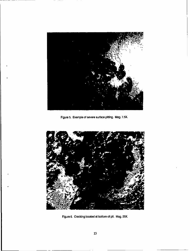
Figure 5. Example of severe surface pitting. Mag. 7.5X.
Figure 6. Cracking located at bottom of pit. Mag. 25X.
13
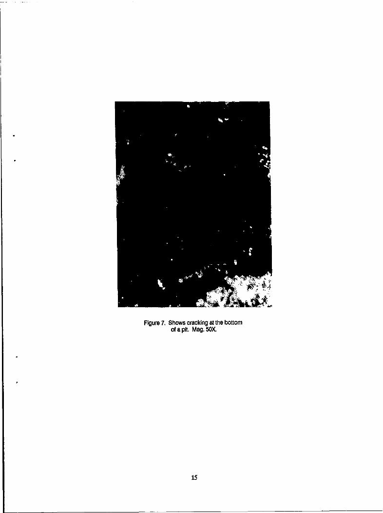
Figure 7. Shows cracking at the bottom
of a pit. Mag. 50X.
15
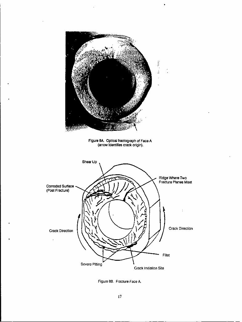
Figure 8A. Optical fractograph of Face A(arrow identifies crack origin).
Shear Up
Ridge Where TwoFracture Planes Meet
Corroded Surface(Post Fracture)
Crack Direction Crack Direction
~Fillet
Severe PittingCrack Initiation Site
Figure 8B. Fracture Face A.
17
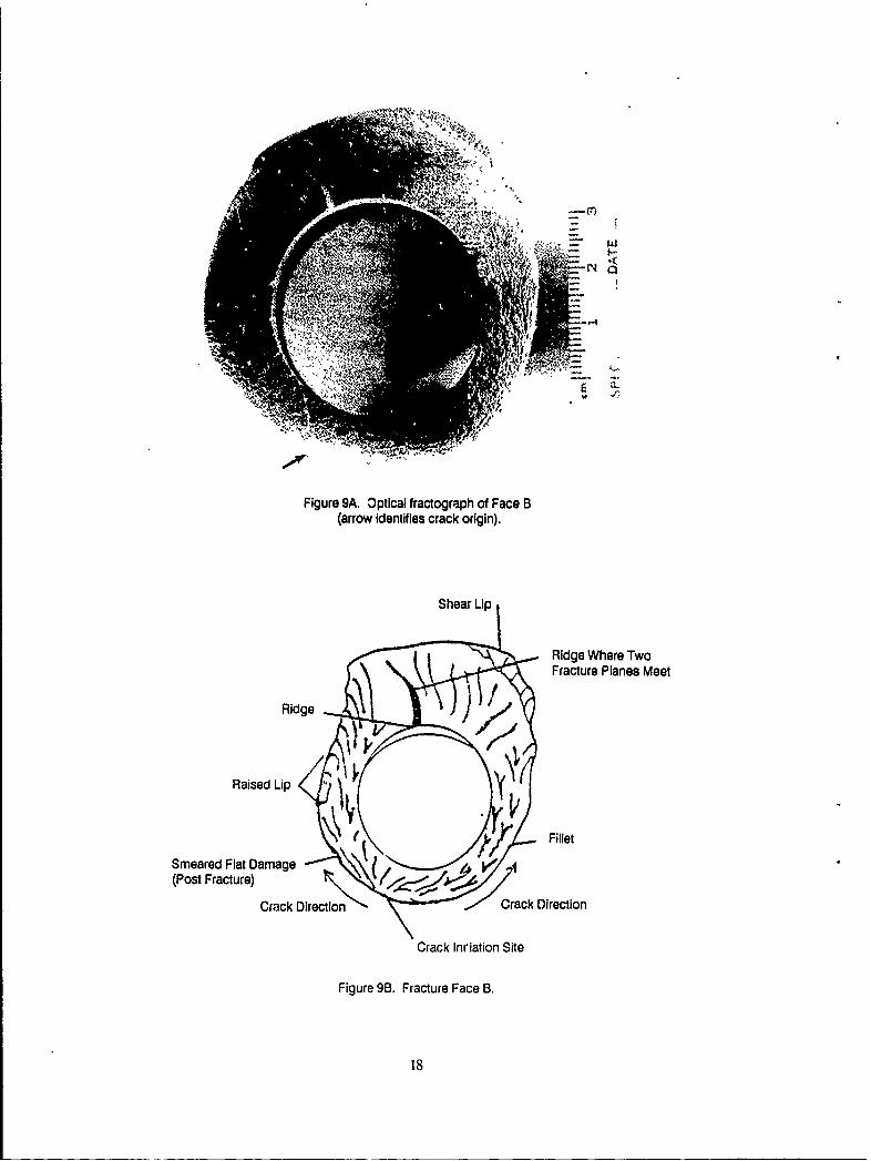
Figure 9A. Optical fractograph of Face B(arrow identifies crack origin).
Shear Lip
Ridge Where TwoFracture Planes Meet
Ridge .,. .
Raised Lip
Smeared Flat Damage Fillet
(Post Fracture)
Crack Direction Crack Direction
Crack Ini'iation Site
Figure 98. Fracture Face B.
18
tFRACTURESURFACE
FRETTEDZONE
Figure 10. Crack~ Initiation site of fractureFace B. Mag. 7.5X.
FRACTURE
PITTINGON RADIUS
Figure 11. Corrosion pits at ,,rack origin of fracture Face B. Mag. 30X.
19
~Fracture
Bushing
Fretting --y
Start at Fillet
Figure 12. Schematic showing location of fracture and fretting.
FRACTURESURFACE
I RADIUS
FRETTEDZONE
Figure 13. Crack Initiation she of fracture Face A. Mag. 7.5X,
21
FRACTURESURFACE
PITTINGON RADIUS
Figure 14. Corrosion pits at crack origin of fracture Face A. Mag. 30X.
Ring Cut From Mixer Support
/ Pitted Cross Section(Mounted Surface)
Longitudinal Cross Section
Transverse Cross Section (Mounted Surface)(Mounted Surface)
Figure 15A. Metallographic cross sections.
23
Fracture Face B
Crack Origin(Mounted Surface)
Figure 15B Metallographic cross sections.
Figure 16. Optical micrograph revealing a fine martensitic structure. Mag. 500X.
25
Figure 17. Shows fine tempered martensite indicative ofprior heat treatment. Mag. 1IOOOX
26
4q
Figure 18. Cross section of crack origin taken through fractureFace B, in the as-polished condition. Mag. 50X.
27
. J.
-10
'$ l
I VI
"j -
7 Soi'.-
Figure 19. Cross section of crack origin takon through fracture
Face B, in the etched condition. Mag. 50X.
28
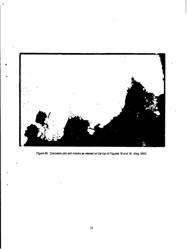
Figure 20. Corrosion pits with cracks as viewed on the top of Figures 18 and 19. Mag. 50OX.
29
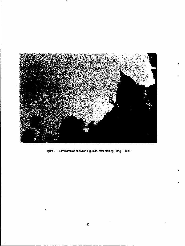
Figure 21. Same area as shown in Figure 20 after etching. Mag. 1500X.
30
S4
Figure 2. Enlarged view of a crack at the bottomof apt. Mag. iSOOX.
31
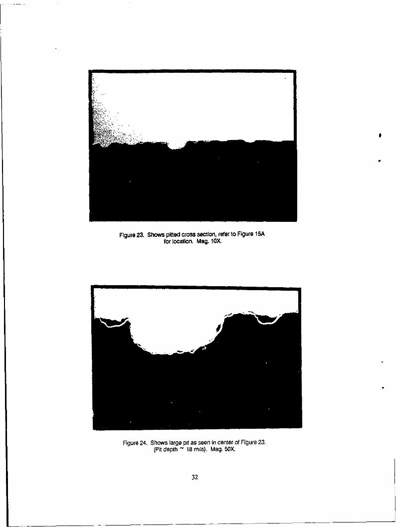
Figure 23. Shows pitted cross section, refer to Figure 15Afor location. Mag. lOX.
Figure 24. Shows large pit as seen in center of Figure 23.
(Pit depth - 18 mils). Mag. 50X.
32
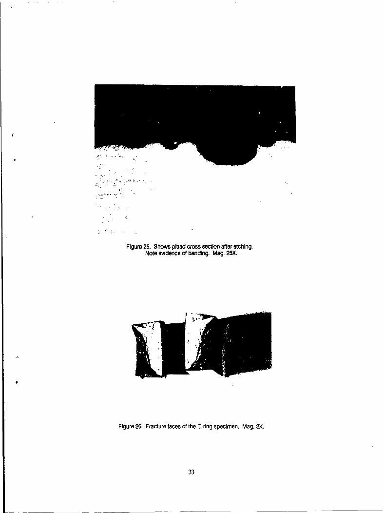
Figure 25. Shows pitted cross section after etching.Note evidence of banding. Mag. 25X.
Figure 26. Fracture faces of the ?-ring specimen. Mag. 2X.
33
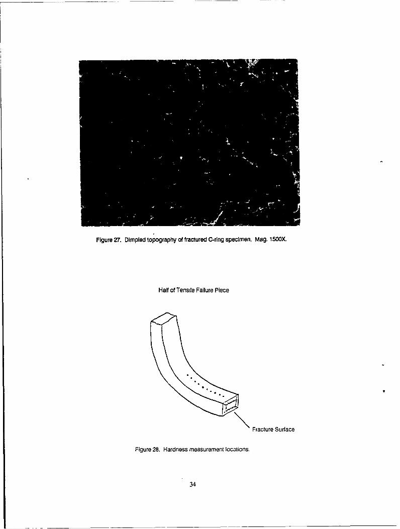
Figure 27. Dimpled topography of fractured C-ring specimen. Mag. 1500X.
Half of Tensile Failure Piece
C9
Fracture Surface
Figure 28. Hardness measurement locations.
34
C)
F- <N
U .
0
0
Ca
)
LA-
35
FRACTURESURFACE
Prl7ED
FRACTURESURFACE
Figures 30 and 31. SEM of pfts along radiuscrack origin. Mag. 75X.
36
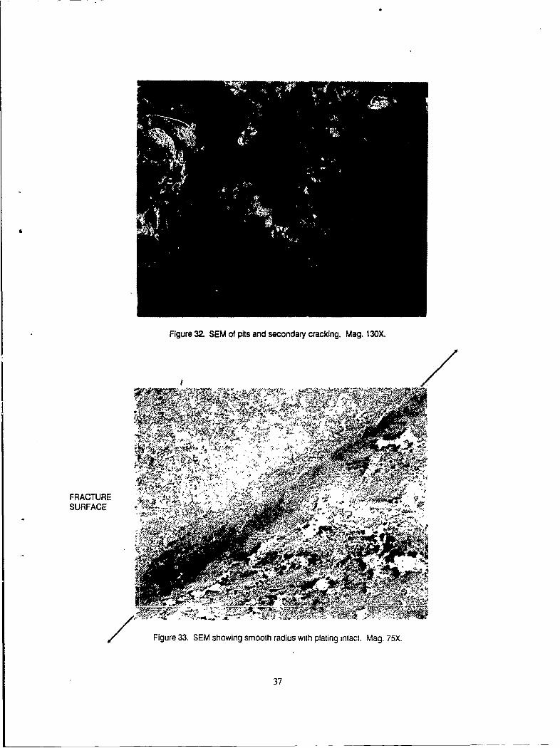
Figure 32. SEM of pits and secondary cracking. Mag. 130X.
FRACTURE14 wSURFACE
Figure 33. SEM showing smooth radius with plating intact. Mag. 75X.
37
LflL
0E
2.EE
:0 :c
CL
ouIIl)
C3a
w 38
II
~Q
I1.1
- Cj
--- --- --
39I.
C,- -' --
CL'
. u1
0
IT)l L'
CL
Ul
uD1
0~40
Ili
4- '.
(nC
dIt
Lg.
CL liS
4-c
Q.
> ~ (
C. 2
(0 '0 I
+) C..)cc
0-4 C
OD
LL
41
10 4m
GJ n
tCL'-
(A CLNcu ila4
L-
IL fl
CLLW~L it
U:
Q co
cC-)
C-D
C', iii
4i
42a
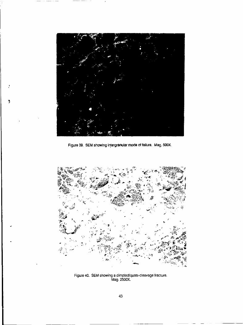
Figure 39. SEM showing intergranular mode of failure. Mag. 500X.
;NZ
'-47
>., < ., , . . , .? "
qi
'AQ7
• > - - ¢ < . " '. -I
Figure 40. SEM showing a dimpled/quasi-cleavage fracture.Mag. 2500X.
43
DISTRIBUTION LIST
No. ofCopies To
I Office of the Under Secretary of Defense for Research and Engineering, ThePentagon, Washington, DC 20301
Commander, Defense Technical Information Center, Cameron Station, Bldg. 5,5010 Duke Street, Alexandria VA 22304-6145
2 ATTN: DTIC-FDAC
I MIAC/CINDAS, Purdue University, 2595 Yeager Road, West Lafayette, IN 47905
Commander, U.S. Army Materiel Command, 5001 Eisenhower Avenue, Alexandria,VA 22333
1 ATTN,, AMCSCI1 AMCQA-P, S. J. Lorber
Commander, Pacific Missile Test Center, Point Mugu, CA 930421 ATTN- John Durda, Code 20411 Carl Louck, Code 20411 John Piercy, Code 20411 Sam Keller, Code 2043I Bill Mcauley, Code 2043
Commander, U.S. Army Laboratory Command, 2800 Powder Mill Road, Adelphl,MD 20783-1145
1 ATTN, AMSLC-IM-TLI AMSLC-CT
Commander, Rock Island Arsenal, Headquarters AMCCOM, Rock Island,IL 61299-6000
1 ATTN: AMSMC-PCA-WM, Joe WellsI AMSMC-QAM-I, Gary Smith1 AMSMC-ASR-M, Brian KunkelI John Housseman
Commander, U.S. Army Test and Evaluation Command, Aberdeen Proving Ground,MD 21005
1 ATTN: Library
1 Clarke Engineer School Library, 3202 Nebraska Ave. North, Ft. Leonard Wood,MO 65473-5000
Naval Air System Command, Department of the Navy, Washington, DC 203601 ATTN:. AIR-O3PAF
Naval Research Laboratory, Washington, DC 203751 ATTN:. Code 5830
Naval Air Development Center, Warminster, PA 189741 ATTN: Code 063
Commander, U.S. Army Aviation Systems Command (AVSCOM) St. Louis,MO 63120-1798
1 ATTN: AMSAV-ECC, Emanuel BuelterI AMSAV-ECC, Robert LawyerI AMSAV-EFM, Frank Barhorst1 AMSAV-EFM, Kirit Bhansali1 AMSAV-E, Carl Smith1 AMCPM-AAH, Dave RobyI AMCFM-AAH, Bob Kennedy
Commander, Corpus Christi Army Depot, Corpus Christi, TX 78419-6195I ATTN, AMSAV-MRPD, Nicholas Hurta, Mail Stop 551 AMSAV-MRPD, Lou Neri, Mail Stop 551 SDSCC-QLM, David Garcia, Mail Stop 27I SDSCC-QLM, charlie Wilson, Mail Stop 27
Commander, Armament Research, Development and Engineering Center,Picatinny Arsenal, ' v7806-5000
1 ATTN: SMCAR-CCS-C, Anthony Sebasto, Bldg. #1
Program Manager, Government-industry Data Exchange, GIDEP Operations Center,Corona, CA 91720-2000
1 ATTN: J. C. Richards, Program Director
Director, U.S. Army Materials Technology Laboratory, Watertown, MA 02172-00012 ATTN: SLCMT-TML4 Authors
r - - - -- - - - - - - - - - - - - - - r - - - - - - - ---- - - - - - - -I
0 . Iiv 1: u Ij.. I0
.. ~I 1i IZE 'r. I E~
L*I .5 1 .0 111
I~~ ~ i sI
. ' 9 _k i I .8
L? p
u~~ ~ ~ c 0hb!.E
0
41 1 1a] am 1 9 11. 0 I
~ ~ S
a~6 o. IT ZiaLU
a~~~0 tstU~f ~ C
TB ''~g l
a ~ I 0 5 .
ar, >- 1-0l z I-O
<Si .181 r< r 1 o &n 5rr 9 , *-,O~ a..uj E s ~ l
>1 Lz-2r~d 0j