Embed Size (px)
Citation preview

HAL Id: hal-03169386https://hal.archives-ouvertes.fr/hal-03169386
Submitted on 19 Mar 2021
HAL is a multi-disciplinary open accessarchive for the deposit and dissemination of sci-entific research documents, whether they are pub-lished or not. The documents may come fromteaching and research institutions in France orabroad, or from public or private research centers.
L’archive ouverte pluridisciplinaire HAL, estdestinée au dépôt et à la diffusion de documentsscientifiques de niveau recherche, publiés ou non,émanant des établissements d’enseignement et derecherche français ou étrangers, des laboratoirespublics ou privés.
Failure analysis of shot–sleeves used in brass highpressure die–casting process
Dorra Abid, Ahmed Ktari, Dhouha Mellouli, Nedia Gafsi, Nader Haddar
To cite this version:Dorra Abid, Ahmed Ktari, Dhouha Mellouli, Nedia Gafsi, Nader Haddar. Failure analysis of shot–sleeves used in brass high pressure die–casting process. Engineering Failure Analysis, Elsevier, 2019,104, pp.177-188. �10.1016/j.engfailanal.2019.05.038�. �hal-03169386�

HAL Id: hal-03169386https://hal.archives-ouvertes.fr/hal-03169386
Submitted on 19 Mar 2021
HAL is a multi-disciplinary open accessarchive for the deposit and dissemination of sci-entific research documents, whether they are pub-lished or not. The documents may come fromteaching and research institutions in France orabroad, or from public or private research centers.
L’archive ouverte pluridisciplinaire HAL, estdestinée au dépôt et à la diffusion de documentsscientifiques de niveau recherche, publiés ou non,émanant des établissements d’enseignement et derecherche français ou étrangers, des laboratoirespublics ou privés.
Failure analysis of shot–sleeves used in brass highpressure die–casting process
Dorra Abid, Ahmed Ktari, Dhouha Mellouli, Nedia Gafsi, Nader Haddar
To cite this version:Dorra Abid, Ahmed Ktari, Dhouha Mellouli, Nedia Gafsi, Nader Haddar. Failure analysis of shot–sleeves used in brass high pressure die–casting process. Engineering Failure Analysis, Elsevier, 2019,104, pp.177-188. �hal-03169386�

Science Arts & Métiers (SAM)is an open access repository that collects the work of Arts et Métiers Institute of
Technology researchers and makes it freely available over the web where possible.
This is an author-deposited version published in: https://sam.ensam.euHandle ID: .http://hdl.handle.net/10985/20015
This document is available under CC BY license
To cite this version :
Dorra ABID, Ahmed KTARI, Dhouha MELLOULI, Nedia GAFSI, Nader HADDAR - Failureanalysis of shot–sleeves used in brass high pressure die–casting process - Engineering FailureAnalysis - Vol. 104, p.177-188 - 2019
Any correspondence concerning this service should be sent to the repository
Administrator : [email protected]

Failure analysis of shot–sleeves used in brass high pressuredie–casting process
Dorra Abida, Ahmed Ktaria,b,⁎, Dhouha Melloulia, Nedia Gafsia, Nader Haddara
a Laboratoire de Génie des Matériaux et Environnement, LGME, ENIS, B.P. 1173–3038, Université de Sfax, Tunisiab Laboratoire MSMP – EA7351, Arts et Métiers ParisTech, Aix-en-Provence, France
A R T I C L E I N F O
Keywords:Shot sleeveDamage assessmentThermal fatigueCrack growthShielding effect
A B S T R A C T
A failure investigation has been conducted on a two cases of shot-sleeve used in brass–die castingand made up of AISI H10 tool steels to study their failure mechanisms. The chemical compositionof the shot–sleeves material and the hardness profiles were evaluated. A preliminary examinationof shot–sleeves reveal the presence of cracks network on their inner surfaces which proves thatthermal fatigue was probably the main cause of their failure. A Meticulous investigation of thesedamaged surfaces reveal the presence of an additional small zone cited in the vicinity of theplunger entry side. This zone presents several scratches sign of abrasive wear. Then, the mea-surement of the cracks length and their linear density along longitudinal and transversal cuts ofthe damaged shot–sleeve sample are carried out. Results show that the observed cracks networkcan be divided into two zones. The first one was the most damaged in terms of cracks density andlength given that it is the first zone which enter in contact with the molten metal. However, thecracks network examined in the second zone appears to be superficial.
1. Introduction
The high pressure die-cast process is used to produce parts mostly from aluminium, magnesium, zinc and copper alloys byinjection of the molten metal in the mold cavity. Parts produced by this process conform accurately to the die size, have favourablemechanical features, and are low in cost. Hence, this process has a wide range of application fields including the aircraft andautomobile industries. During hot forming operations the tools steel used to this process are exposed to a sever thermal and/ormechanical loads which can lead to their damage. The improvement of these structures lifetime was strongly required due to severaleconomic and environmental reasons. One of the major damage mechanisms occurring in hot forming tool steels, under cyclicthermal loads (e.g. die casting and forging [1–4]), is the formation of a network of interconnected cracks, often named Heat–Checking[5–8]. The stress cracking, which presents another variant of thermal fatigue cracks, was clearly marked in areas exposed to localstress concentrations and can lead to crack initiation in a die casting mold [9]. Then, these cracks can grow and became morepronounced driven by several factor including thermal fatigue, erosion, oxidation, soldering of the metal to the die surface, de-formation of die contact surfaces and dangerous fracture [10–13].
In hot metal forming applications like stamping or die casting the service life time of the tools are limited due to their extremeworking conditions in term of thermal and/or mechanical loads which result from the close contact between the tools and the hotwork piece. In these applications the tools temperature can reach 1200 °C [13] when the molten metal attain 675 °C and 930 °C forAl–alloy casting and Cu–alloy casting respectively [14].
⁎ Corresponding author at: Laboratoire de Génie des Matériaux et Environnement, LGME, ENIS, B.P. 1173–3038, Université de Sfax, Tunisia.E-mail address: [email protected] (A. Ktari).
https://doi.org/10.1016/j.engfailanal.2019.05.038Received 7 April 2018; Received in revised form 22 May 2019; Accepted 30 May 2019Available online 04 June 2019
T

Fig. 1. Geometry and dimensions of the studied shot–sleeves.
Table 1Process parameters in high pressure brass die–casting caseof study.
Shot–sleeve filling 2.5 sInjection phase 0.1 sCooling phase 27 sCompression 4 sEjection and mold coating 23 sMolten metal temperature 950 °CCast ejection temperature 300 °C
Table 2Chemical composition of the studied material and usual steels gradesused in hot work tools (% in weight).
C Si Mn P S Cr Mo V
Studied material 0.304 0.242 0.303 0.025 0.005 2.89 2.71 0.61AISI H10 0.28–0.35 0.1–0.4 0.15–0.4 0–0.03 0–0.02 2.7–3.2 2.5–3.0 0.4–0.7AISI H13 0.35–0.42 0.8–1.2 0.25–0.5 0–0.03 0–0.02 4.8–5.5 1.2–1.5 0.85–1.15
Fig. 2. Microstructure of the shot-sleeve: (a) Light Optical Microscopy (LOM), (b) The SEM microanalysis.

Under such working conditions, the tools are generally damaged through wear and thermal fatigue cracking processes [15–18].Ktari et al. [19] have investigated a diesel engine crankshafts fracture used in train. Mellouli et al. [20] have investigated the thermalfatigue failure of a prematurely failed brass die-casting.
To improve the structures lifetime several researches have been conducted to study the effect of surface coatings on thosestructure lives. Panjan et al. [12] have studied the effect of duplex treatment composed of plasma nitriding and the deposition of 4-mm-thick PVD CrN coating on die-casting tools. They have found that wear of duplex treated tool is smaller than wear of the plasmanitrided tool. In addition, Srivastava et al. [21] have studied the effect of three-layer coating architecture on die surface: the outerlayer consists of a thermal barrier coating composed of rare-earth oxide, the middle one is a TiAlN diffusion barrier coating and theinner layer is a thin adhesive Ti layer. These authors have found that this coating can significantly improves the thermal fatigueresistance of the substrate. Klobčar et al. [22] have studied the effect of cladding with maraging steels; they have found that thistreatment provides good thermal fatigue resistance to the treated metal. The functionally graded materials (FGM) were also appliedas a solution to improve the structure lifetime. Fazarinc et al. [23] have studied several FGM surfaces by changing amounts ofalloying elements, precisely Si and Mo, they have found that their resistance to thermal fatigue is estimated at 27 times more resistantthan the basic material.
In our case of study, two failed structures named shot–sleeve have been examined. This structure is a part of the die–castinginjection press sited on the fixed mold side between the injection plunger and the sprue bush. In service, during the hot formingoperations, the shot–sleeve undergo severe cyclic thermal–mechanical loads (i.e. the alternating of compressive and tensile stresses atthe surface that arise from differential thermal expansion / contraction during sudden transient temperature changes [15,24]) whichcan lead to cracks initiation and propagation. The investigation of the thermo–mechanical fatigue shot sleeve was conducted ac-cording to the following points:
• Chemical and mechanical characterization of the shot sleeve material.
• Analysis of the failed zones to understand the main causes and mechanisms leading to the shot sleeve structures.
2. Shot sleeve materials characterization
In the present study, samples of shot–sleeve failed in service, were investigated to understand the mechanisms, which can lead totheir damage. The shot–sleeve (Fig. 1), used in brass high pressure die–casting process, undergoes a severe thermo–mechanicalloadings during cast cycles. Each cycle include principally four phases as following:
(i) The filling of the shot sleeve with the molten metal by means of a ladle,(ii) The plunger moves through the shot–sleeve and press the casting material into the mold,(iii) The cooling phase begin once the mold has been filled with molten metal and keep on until the casting cold. During the first part
of this phase, named compression, a pressure is applied to the cooling metal by means of the plunger until the alloy hassolidified.
(iv) The mold is then opened and the casting is removed with the ejector pins and the internal surfaces of the mold are sprayed with alubricant before every cycle.
After the casting has been removed and the lubricant applied to the mold surfaces, the die are clamped together again then thecycle will repeat itself. The high pressure brass die–casting process parameters are summarized Table 1.
Fig. 3. Dimensions of tensile specimen (in mm).
Table 3Monotonic mechanical properties of AISI H10 steel grade at room temperature.
Young's modulus [GPa] Poisson's ratio Yield strength Re[MPa] Tensile strength Rm[MPa] A%
220 0.3 1580 1720 0.28

Fig.
4.Cha
rpyV-notch
specim
ens:
(a)Geo
metry
anddimen
sion
s(inmm),(b)machine
dCha
rpyV-notch
specim
ens.

2.1. Chemical analysis and microstructure
The chemical analysis of a sample of steel taken from damaged shot–sleeve was determined by means of a spectrometer (JobinYvon JY 48®). The typically steel grades used for hot work tools and our studied material are summarized in Table 2.
Materials used in high pressure die–cast process equipments have to combine a multitude properties to resist production con-straints that they face. According to Reynoldson [25], a good material need to have: (i) low chemical reactivity with the surroundingenvironment (molten metal and oxygen), (ii) low thermal expansion and high thermal conductivity coefficients, (iii) high temperingresistance and (iv) a good toughness.
Both steel grades H10 (32CrMoV12–28) and H13 (X40CrMoV5–1) possess good resistance to abrasive effects, low sensibility tothermal shocks and good dimensional stability. However, H10 presents relatively high wear resistance compared to AISI H13 steelgrade. The contents in chromium, molybdenum and vanadium give good hardenability, wear resistance, fracture toughness andhardness properties at high temperatures [26]. The chromium increases the hardenability of the steel, decreases the grain growthduring austenitization, delay the softening during the tempering and contribute to the reduction of the high–temperature oxidation[27]. The molybdenum slows down the steel softening and give it a very good wear resistance at high temperature through thepresence of hard metallic carbides M6C and M2C with a hardness of 1500 and 2000HV respectively [27]. The vanadium allows togenerate a very high carbides hardness (MC≈ 3000HV). It added generally, with a small amount, with chromium, molybdenum andtungsten to avoid the harmful oxidation resistance beyond 600 °C. The decrease of corrosion resistance is compensated by thepresence of chromium [27].
Our studied material is H10, a metallographic observations were realized by means of an optical microscope (Leica®) on the sametaken sample polished until mirror state then attacked by Nital (5% of nitric acid diluted in methanol). These observations show thepresence of a martensitic structure (Fig. 2).
2.2. Mechanical properties
2.2.1. Tensile propertiesIn order to investigate the tensile properties of the studied material AISI H10, tensile tests were carried out on a three standard flat
tensile specimens (NF A 03–151) as presented in Fig. 3. The semi–finishing form of each one was obtained from the damaged
Fig. 5. Fracture surface of Charpy specimen. (a) macroscopic observation, (b) binocular microscope observation.
Fig. 6. CAO schema of shot–sleeve cutting planes: (a) Initial shot sleeve shape, (b) After the longitudinal EDM cut, (c) Cross-section cut plans.

shot–sleeve case using a wire EDMmachine. Then, specimens flat surfaces were mechanically grinding to obtain a good surface finish.These tests were conducted on a universal testing machine with capacity of 50 kN and a crosshead speed of 0.5 mm/s. The obtainedresults average are summarized in
Table 3.
2.2.2. The material toughnessStandard Charpy V-notched specimens were machined from the failed shot-sleeve by a wire EDM machine (Fig. 4). Then, three
tests were conducted at room temperatures to determine the material toughness. The average of the measured CVN energy(CVN=3.4 ± 0.1 J) and the feature of the fractured surface prove the brittle nature of the specimen material (Fig. 5).
2.2.3. Hardness analysisThe hardness profiles were measured, on a shot–sleeve longitudinal section (Fig. 6 (b)) polished until mirror state, from the entry
plunger zone to the mold side and from the inner to the outer surface (Fig. 7). These profiles are performed with a Vickers hardnessmachine using a load of 15 kg. The measured profiles reveal that the hardness appears to be constant for all tested samples.
The original hardness of the shot–sleeve as provided by manufacturer technical data–sheet was about 42–44 HRC. However, the
25
30
35
40
45
50
0 2 4 6 8 10 12 14 16
hard
ness
(H
RC
)
Depth (mm)
25
30
35
40
45
50
0 50 100 150 200
Har
dnes
s (H
RC
)
Distance (mm)
(a)
(b)
Outer surface
Inner surface
Plunger entry side
Moldside
Fig. 7. Hardness shot–sleeve profiles, (a) from the entry to the mold zones, (b) from inner to the outer surfaces.
Fig. 8. Cracks network observed on the inner surface of the damaged shot–sleeve.

average of measured hardness is about of 44.8−2.4+3.8 HRC. This shows that the hardness was remained quasi–constant even after a
few thousands of thermal heating and cooling phases (more than 74,000 cycles) and which indicate that the mechanical behaviour ofthe material is stable (i.e. absence of significant cyclic hardening or softening) under service conditions. Furthermore, micro-hardnessmeasurements were performed with a Wilson hardness machine 402MVD using a load of 1 kg at a distance of approximately 400 μmfrom the inner surface. The average of measured micro-hardness is about 49.8−6.4
+5.5 HRC. This result proves that is no significantincrease of the hardness from the heart to the inner surface of the shot-sleeve.
3. Expertise of the damaged shot-sleeves
The metallic structures, which undergo severe cyclic thermo–mechanical loads in service, are typically characterized by thepresence of several cracks. These cracks are the most dangerous defects in term of lifetime on which we have to grant a particularattention. In our study, two shot–sleeves damaged in service, supplied by SIAM company, were investigated to determine the
Fig. 9. Shot–sleeve inner surface damage observed with a digital camera.
0
1
2
3
4
5
6
7
0 40 80 120 160 200
Cra
ck d
epth
(m
m)
Shot sleeve length (mm)
Zone 2Zone 1 Zone 3
Fall zone
Lmax= 6.27 mmLaverage =1.66 mm
Crack's density = 0.69 crack/mm
Lmax= 3.21 mmLaverage = 0.34 mmCrack's density = 1.59 crack/mm
Fig. 10. Crack lengths distribution along the shot sleeve (longitudinal sectionθ=0).

mechanisms leading to their damages.The first and the second shot–sleeves have been failed after respectively 46,000 and 74,000 cycles. This corresponds to a quantity
of injected molten metal of 18,000 kg and metal27,000 kg which give an average volume/cycle of 0.39 kg and 0.36 kg, respectively. In addition, only the brass was used as molten
metal in these two studied shot-sleeves. According to these previous data, the first shot-sleeve was failed at smaller number of cycles.Which can be explained by the fact that the average of the injected volume per cycle is significantly more important for the first shot-sleeve compared to second one (more than 8.3%).
According to the chemical composition, the microstructure and the preliminary damage observations carried on both shot-sleevesit is obvious that both shot-sleeves are made from the same steel grade (AISI H10) and present the same damage morphology;however, the second shot-sleeve present a more pronounced crack network. As a result, the second shot- sleeve was chosen to conductthe subsequent of the investigation.
(A) Zone 2 : mm37 from the plunger entry side
(B) Zone 2 : mm81 from the plunger entry side
(C) Zone 3 : mm165 from the plunger entry side
0
5
10
15
20
25
300 5 10 15 20 25 30 35 40 45
Cra
ck d
epth
(*1
0mm
)
Angle (degree)
Lmax= 2.5 mmLavrage= 0.6 mmCrack's number = 46
0
5
10
15
20
250 5 10 15 20 25 30 35 40 45
Cra
ck d
epth
(*1
0mm
)
Angle (degree)
Lmax= 2.1 mmLaverage= 0.32 mmCrack's number = 44
0
50 5 10 15 20 25 30 35 40 45
Cra
ck d
epth
(*1
0mm
)
Angle (degree)
Lmax = 0.2mmLaverage = 0.12mmCrack's number = 25
1.5 mm
1.5 mm
1.5 mm
Fig. 11. Crack distribution of damaged shot–sleeve in cross–sections A, B and C.
3.1. Observation of the damaged surfaces
The second shot–sleeve was cut with a wire EDM machine according to their longitudinal direction to examine the integrity of thedamaged surface (Fig. 8). After that, the cut–out parts are subjected to a surface cleaning operations: A chemical pickling with analkaline solution using a dilute nitric acid was performed, at room temperature, to eliminate all traces of oxides. Then, the damagedshot–sleeve surfaces were subjected to a preliminary assessment with a naked eye to identify their major damage features. Theexamined surfaces (Fig. 9) clearly show the presence of a cracks network on the inner shot–sleeve surfaces.
A finer observations of the shot–sleeve inner side were carried out after a longitudinal cut (Fig. 6 (b)). The examination of thedamaged surfaces was made using an experimental device equipped with a digital Baumer® camera GIgE (8 bits). This camera isequipped with a CCD sensor allowing to have a resolution of 1624× 1236 pixels. Several photos are taken and then assembled bymeans of Photoshop® software to obtain a large image that cover the entire shot–sleeve examined surface (Fig. 9). This surface revealsthe presence of three different zones. The first one is located in the plunger entrance side. It presents a number of scratch accordingthe longitudinal direction which corresponds to abrasive wear caused by the friction between the plunger and the shot–sleeve. Thesecond one corresponds to the first zone which enter in contact with the molten metal (T=950 ° C). It undergo cyclic thermal shocks.This zone appears to be the most damaged surface in the shot–sleeve. It presents a dense crack network sign of the thermal fatigue. Inaddition, the investigation of this zone according to the OθZ plan shows that some cracks, after initiation, were propagated in depthalong the radial direction (Detail A). The last zone reveals also the presence of a crack network however it is less dense compared tothis observed in the 2nd zone (Fig. 9).
3.2. Quantitative study of the cracks network
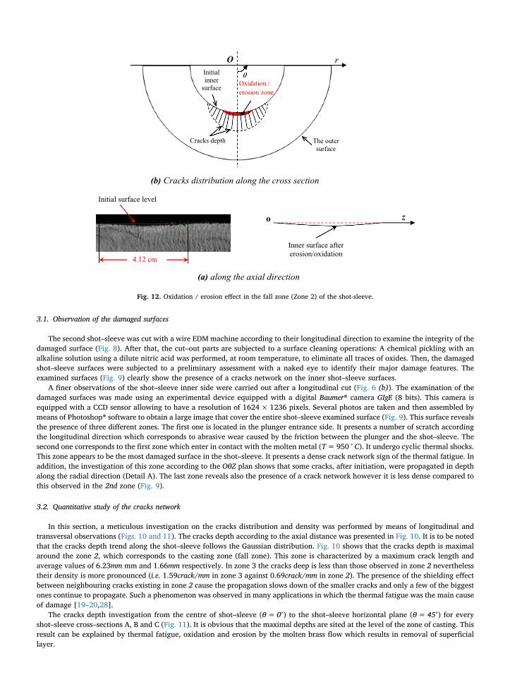
In this section, a meticulous investigation on the cracks distribution and density was performed by means of longitudinal andtransversal observations (Figs. 10 and 11). The cracks depth according to the axial distance was presented in Fig. 10. It is to be notedthat the cracks depth trend along the shot–sleeve follows the Gaussian distribution. Fig. 10 shows that the cracks depth is maximalaround the zone 2, which corresponds to the casting zone (fall zone). This zone is characterized by a maximum crack length andaverage values of 6.23mm mm and 1.66mm respectively. In zone 3 the cracks deep is less than those observed in zone 2 neverthelesstheir density is more pronounced (i.e. 1.59crack/mm in zone 3 against 0.69crack/mm in zone 2). The presence of the shielding effectbetween neighbouring cracks existing in zone 2 cause the propagation slows down of the smaller cracks and only a few of the biggestones continue to propagate. Such a phenomenon was observed in many applications in which the thermal fatigue was the main causeof damage [19–20,28].
The cracks depth investigation from the centre of shot–sleeve (θ=0°) to the shot–sleeve horizontal plane (θ=45°) for everyshot–sleeve cross–sections A, B and C (Fig. 11). It is obvious that the maximal depths are sited at the level of the zone of casting. Thisresult can be explained by thermal fatigue, oxidation and erosion by the molten brass flow which results in removal of superficiallayer.
r O
4.12 cm
Cracks depth
Oxidation / erosion zone
Initial inner
surface
The outer surface
(a) along the axial direction
(b) Cracks distribution along the cross section
Inner surface after erosion/oxidation
Initial surface level
o z
Fig. 12. Oxidation / erosion effect in the fall zone (Zone 2) of the shot-sleeve.

Fig.
13.SE
Mob
servationof
ada
mag
edshot
sleeve
cross-section:
(a)Sh
ort(initiation)
andde
epcrack,
(b)Zo
omon
theexam
ined
crackwithED
S(point
1).

The initial level of the shot–sleeve casting zone (cited in zone 2) was decreased probably due to oxidation and erosion effects asshown in Fig. 12. The cracks situated surroundings the shot–sleeve centre (near θ=0°) are in reality longer compared to theireffective length due to the small decrease of the shot sleeve inner surface level produced after the oxidation / erosion effect. Othersmicro cracks are totally removed what favoured the propagation of persistent cracks because the motive force was located in them, isconfirmed by previous research [1,29].
In addition, in order to more understand the mechanisms leading to the shot sleeve failure, a sample of the cross-section surfacewas examined using SEM (Fig. 13) and Energy Dispersive X-ray Spectroscopy (EDS) to identify the chemical composition of the metalinside cracks (points 1 in Fig. 13 (b)) (Table 4). According to Fig. 13 (a), the cracks tend to propagate perpendicular to the damagedsurface. The initial growth of thermal fatigue cracks is facilitated by an oxidation attack on the crack surface, which forms the Fe, Cu,Zn, Cr, Mo, Si and O rich layer (Table 4). The presence of brass and oxides, in the cracks increases plastic yield (Rp0.2) and com-pressive stresses during the heating phase of the thermal cycle [30]. As a result, the tensile stress is further increased during thecooling phase and can leads to the acceleration of the crack growth rate. In addition, the tensile stresses applied on the shot-sleeveinner surface during the cooling phase combined with the erosion phenomenon caused by the molten brass fall in the second zoneleads to a local failure, which promote the opening of thermal cracks [13]. These cracks act as channels allowing oxygen to penetratedown to the crack tip area and oxidize both shot sleeve and the filling material. Solidified particles down on the crack act as anobstacle for its closer and the size of the crack openings in the filling material indicates the amount of brass that will fill the crackduring the next cycle [20].
4. Conclusions
The investigation of a failed shot–sleeves used in high pressure brass die–casting was carried out in this study. The failed shot-sleeve was at first investigated by the determination of chemical composition, microstructures and hardness. The cracks surfacenetwork, observed at the inner surfaces of all the examined shot–sleeves, were shown the presence of three different zones: (i) enteredpiston, (ii) entrance of the molten metal and (iii) exit of the molten metal. These zones differ by their feature, cracks network densityand depths. The longitudinal section shows that the second zone possess the maximum values of cracks depth. In addition, the crosssection shows that the maximal cracks length are situated in the vicinity of the shot–sleeve centre (θ≈ 0°). According to the foregoingdiscussion it is clear that thermal fatigue is the first cause of shot–sleeve damage. However other phenomena like oxidation anderosion of the shot-sleeve inner surface cause the increases of the damage rate mainly in the casting zone (fall zone).
Acknowledgements
The authors would like to thank Mr. H. Ammar the Head manager of SIAM for fruitful discussions about shot–sleeves failuremode, the material support and for chemical analysis of the studied steel samples.
References
[1] B. Miquel, S. Jean, S. Le Roux, P. Lamesle, F. Rézaï-Aria, Heat checking of hot work tool steels, Proceedings of the 9th International Conference on Temperature-fatigue Interaction, 2002, pp. 185–193.
[2] A. Srivastava, V. Joshi, R. Shivpuri, Computer modeling and prediction of thermal fatigue cracking in die-casting tooling, Wear 256 (2004) 38–43.[3] A. Persson, S. Hogmark, J. Bergström, Thermal fatigue cracking of surface engineered hot work tool steels, Surf. Coat. Technol. 191 (2005) 216–227.[4] S. Le Roux, F. Medjedoub, G. Dour, F. Rézaï-Aria, Role of heat-flux density and mechanical loading on the microscopic heat-checking of high temperature tool
steels under thermal fatigue experiments, Int. J. Fatigue 51 (2013) 15–25.[5] S. Jean, B. Miquel, S. Le Roux, F. Rézaï-Aria, An investigation on heat checkingof hot work tool steels, Proceedings of the 5th International Conference on
Tooling, Tool Steels of the Next Century, University of Leoben, Austria, September 29–October 1, 1999, pp. 185–193.[6] F. Medjedoub, G. Dour, F. Rezaï-Aria, P. Hairy, Endommagement par faïençage des moules de fonderie sous pression en fatigue thermique: origines, mécanismes
et approches, Fonderie Fondeur d'Aujourd'hui 244 (2005) 22–37 (in French).[7] L.A. Norström, M. Svensson, N. Öhrberg, Thermal fatigue behaviour of hot work tool steels, Metals Technol. 10 (1981) 376–381.[8] A. Persson, S. Hogmark, J. Bergström, Simulation and evaluation of thermal fatigue cracking of hot work tool steels, Int. J. Fatigue 26 (2004) 1095–1107.[9] R. Danzer, F. Sturm, A. Schindler, W. Zlepping, Thermal fatigue cracks in pressure die casting dies, Giessereipraxis 19/20 (1983) 287–297.
[10] B. Kosec, L. Kosec, J. Kopač, Analysis of casting die failures, Eng. Fail. Anal. 8 (2001) 355–359.[11] R.W. Neu, H. Sehitoglu, Thermo-mechanical fatigue, oxidation, and creep. Part 1: damage mechanisms, Metal Trans. A. 20A (1989) 1755–1767.[12] P. Panjan, M. Čekada, R. Kirn, M. Soković, Improvement of die-casting tools with duplex treatment, Surf. Coat. Technol. 180 (2004) 561–565.[13] D. Mellouli, N. Haddar, A. Köster, H.F. Ayedi, Hardness effect on thermal fatigue damage of hot-working tool steel, Eng. Fail. Anal. 45 (2014) 85–95.[14] J. Tidlund, Heat checking in hot work steels, 2nd International Colloquium on Tool Steels for Hot Working, Saint Etienne (France), 1977, pp. 1–38.[15] L. Cser, M. Geiger, K. Lange, J.A.G. Kals, M. Hänsel, Tool life and tool quality in bulk metal forming, Proc. Inst. Mech. Eng. 207 (1993) 223–239.[16] A. Skumavc, J. Tušek, A. Nagode, D. Klobčar, Thermal fatigue study of tungsten alloy WNi28Fe15 cladded on AISI H13 hot work tool steel, Surf. Coat. Technol.
285 (2016) 304–311.[17] C.M.D. Starling, J.R.T. Branco, Thermal fatique of hot work tool steel with hard coatings, Thin Solid Films 436 (1997) 308–309.[18] S. Malm, L.A. Norström, Material-related model for thermal fatigue applied to tool steels in hot work applications, Metal Sci. (September) (1979) 544–550.
Table 4The chemical composition inside crack area (EDS).
Fe Cu Zn O Si S Cr Mo
Point 1 5.61 57.03 24.09 1.58 0.13 0.32 0.39 0.77

[19] A. Ktari, N. Haddar, H.F. Ayedi, Fatigue fracture expertise of train engine crankshafts, Eng. Fail. Anal. 18 (2011) 1085–1093.[20] D. Mellouli, N. Haddar, A. Köster, H.F. Ayedi, Thermal fatigue failure of brass die-casting dies, Eng. Fail. Anal. 20 (2012) 137–146.[21] A. Srivastava, V. Joshi, R. Shivpuri, R. Bhattacharya, S. Dixit, A multilayer coating architecture to reduce heat checking of die surfaces, Surf. Coat. Technol. 163
(2003) 631–636.[22] D. Klobčar, L.K.J. Kosec, B. Kosec, J. Tušek, Thermo fatigue cracking of die casting dies, Eng. Fail. Anal. 20 (2012) 43–53.[23] M. Fazarinc, T. Muhič, G. Kugler, M. Terčelj, Thermal fatigue properties of differently constructed functionally graded materials aimed for refurbishing of
pressure-die-casting dies, Eng. Fail. Anal. 25 (2012) 238–249.[24] S. Jean, B. Miquel, S. Leroux, F. Rézaï-Aria, An investigation on heat checking of hot work tool steels, in: F. Jeglitsch, R. Ebner, H. Leitner (Eds.), Tool Steels of
the Next Century, Proceedings of the 5th International Conference on Tooling, University of Leoben, Leoben, Austria, 1999, pp. 185–193.[25] R. Reynoldson, Die Casting Tools Manufactured From H13 Hot Work Tool Steels, Die Casting and Technology, (September 1998), pp. p39–p49.[26] H. Bayrakçeken, S. Tasgetiren, F. Aksoy, Failure of a single cylinder engines crank shafts, Eng. Fail. Anal. 14 (2007) 725–730.[27] R. Lévêque, Données numériques sur les aciers à outils, Techniques de l'Ingénieur : Etude et propriétés des métaux, M 332 V1, 1995, pp. 1–37 (in French).[28] V. Maillot, A. Fissolo, G. Degallaix, S. Degallaix, Thermal fatigue crack networks parameters and stability: an experimental study, Int. J. Solids Struct. 42 (2005)
759–769.[29] F. Medjedoub, S. Le Roux, G. Dour, F. Rézaï-Aria, Effect of local stress on the heat-checking morphology in high temperature tool steels under thermal fatigue:
transition from multi-axiality to uniaxiality, Mech. Mater. 69 (2014) 159–172.[30] D. Klobčar, J. Tušek, B. Taljat, Thermal fatigue of materials for die-casting tooling, Mater. Sci. Eng. A 472 (2008) (2008) 198–207.