Embed Size (px)
Citation preview
TECHNICAL ARTICLE—PEER-REVIEWED
Failure Analysis of Induction Hardened Automotive Axles
C. Kendall Clarke Æ Don Halimunanda
Submitted: 28 November 2007 / Accepted: 16 May 2008
� ASM International 2008
Abstract Rollover accidents in light trucks and cars
involving an axle failure frequently raise the question of
whether the axle broke causing the rollover or did the axle
break as a result of the rollover. Axles in these vehicles are
induction hardened medium carbon steel. Bearings ride
directly on the axles. This article provides a fractography/
fracture mechanic approach to making the determination of
when the axle failed. Full scale tests on axle assemblies and
suspensions provided data for fracture toughness in the
induction hardened outer case on the axle. These tests also
demonstrated that roller bearing indentions on the axle
journal, cross pin indentation on the end of the axle, and
axle bending can be accounted for by spring energy release
following axle failure. Pre-existing cracks in the induction
hardened axle are small and are often difficult to see
without a microscope. The pre-existing crack morphology
was intergranular fracture in the axles studied. An estimate
of the force required to cause the axle fracture can be made
using the measured crack size, fracture toughness deter-
mined from these tests, and linear elastic fracture
mechanics. The axle can be reliably said to have failed
prior to rollover if the estimated force for failure is equal to
or less than forces imposed on the axle during events
leading to the rollover.
Keywords Brittle fracture � Fracture mechanics �Critical crack size � Intergranular cracking � Axle failure �Induction hardened axle � Cleavage fracture
Introduction
Current practice in automobile and light truck design uses
induction hardened axles in which the axle itself serves as
the inner race for the outer bearings. Semi-float axles found
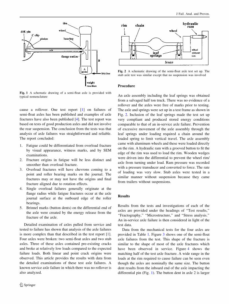
in light trucks (Fig. 1) use roller bearings for the outer
bearings riding on the axle. Stub axles use ball bearings
that run on induction hardened axles and are bolt on
assemblies. Both designs are usually made from 1050 steel
or similar steel with increased manganese for hardenability
[1]. Semi-float axles are induction hardened from the axle
flange radius and along most of the length of the axle. The
axles are direct quenched in the induction hardening pro-
cess and then low temperature tempered. Examination of
axles reveals they usually have a clear martensite outer
case depth of at least 2 mm and hardness values in this
region of 58–60 HRC. A case hardness of at least 58–60
HRC is considered necessary for the journal to function as
an inner race and support the bearing loads [2, 3].
Failure of a rear axle on a vehicle can cause a rollover
under certain conditions. These conditions usually occur in
SUVs because of their higher center of gravity. The highest
axle stresses occur during loading of the wheel in a severe
yaw (or side skid). The tire pavement friction generates a
lateral bending force on the axle. The new, larger diameter
wheels with high-performance tires (better coefficient of
friction or road grip) have raised the tire patch forces on the
wheel and axle thus increasing the stresses that the axle
must withstand. Vertical forces in the plane of the wheel
produce much lower axle stresses because of the smaller
moment arm from the wheel (dimension A vs. B in Fig. 1).
Determining whether an axle broke and caused a roll-
over or whether it broke as a result of the rollover has been
a major issue in many accident investigations. There are
numerous opinions about whether axles can even break and
C. K. Clarke (&) � D. Halimunanda
Metallurgical Consulting, Mobile, AL, USA
e-mail: [email protected]
D. Halimunanda
e-mail: [email protected]
123
J Fail. Anal. and Preven.
DOI 10.1007/s11668-008-9148-3
cause a rollover. One test report [1] on failures of
semi-float axles has been published and examples of axle
fractures have also been published [4]. The test report was
based on tests of good production axles and did not involve
the rear suspension. The conclusion from the tests was that
analysis of axle failures was straightforward and reliable.
The report concluded:
1. Fatigue could be differentiated from overload fracture
by visual appearance, witness marks, and by SEM
examinations.
2. Fracture origins in fatigue will be less distinct and
smoother than overload fracture.
3. Overload fractures will have chevrons coming to a
point and roller bearing marks on the journal. The
fractures may or may not have the origins and final
fracture aligned due to rotation effects.
4. Single overload failures generally originate at the
flange radius while fatigue fractures occur at the axle
journal surface at the outboard edge of the roller
bearings.
5. Brinnel marks (button dents) on the differential end of
the axle were created by the energy release from the
fracture of the axle.
Detailed examination of axles pulled from service and
tested to failure has shown that analysis of the axle failures
is more complex than that described in the test report [1].
Four axles were broken: two semi-float axles and two stub
axles. Three of these axles contained pre-existing cracks
and broke at relatively low loads compared to the expected
failure loads. Both linear and point crack origins were
observed. This article provides the results with data from
the detailed examinations of these test axle failures. A
known service axle failure in which there was no rollover is
also analyzed.
Procedure
An axle assembly including the leaf springs was obtained
from a salvaged half ton truck. There was no evidence of a
rollover and the axles were free of marks prior to testing.
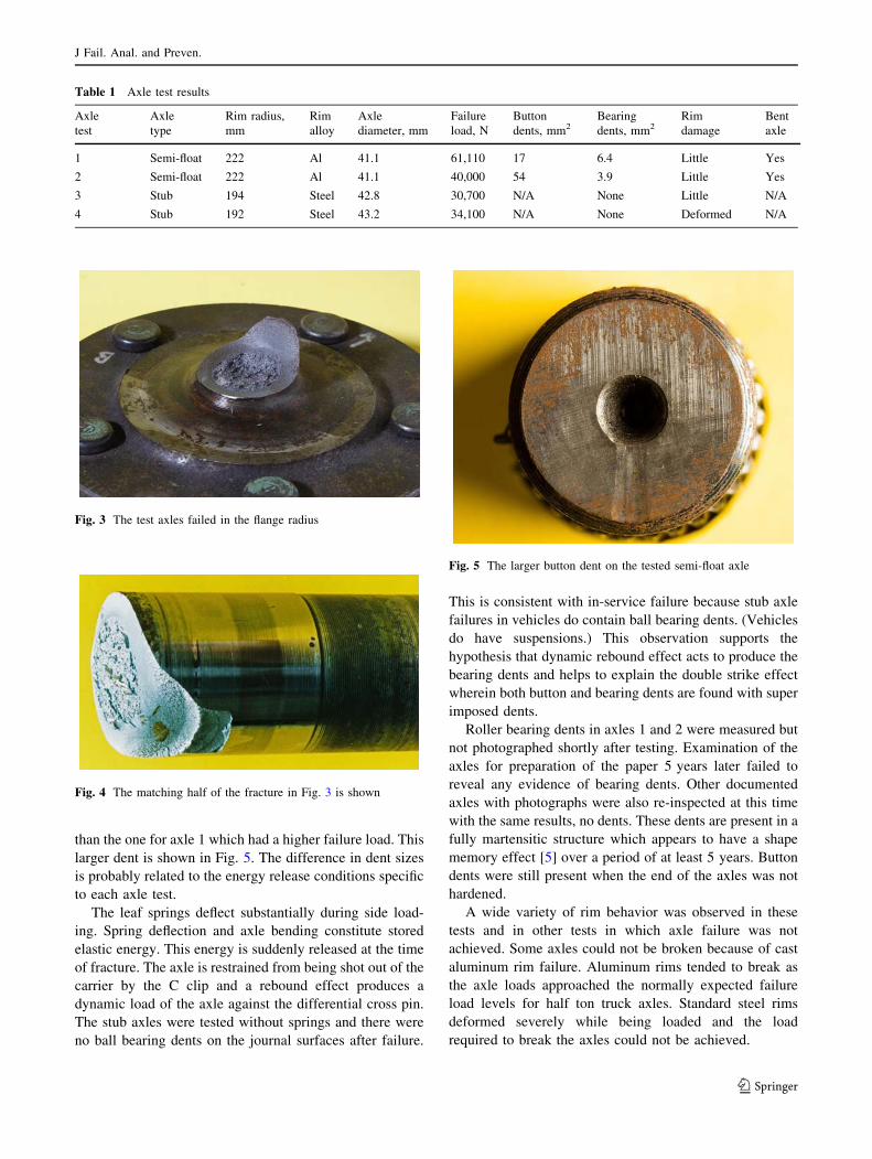
The axle and springs were set up in a test frame as shown in
Fig. 2. Inclusion of the leaf springs made the test set up
very compliant and produced stored energy conditions
comparable to that of an in-service axle failure. Prevention
of excessive movement of the axle assembly through the
leaf springs under loading required a chain around the
loaded spring to limit vertical travel. The axle assembly
came with aluminum wheels and these were loaded directly
on the rim. A hydraulic ram with a grooved button to fit the
edge of the rim was used to load the rim. Wooden wedges
were driven into the differential to prevent the wheel rim/
axle from turning under load. Ram pressure was recorded
with a pressure transducer and converted to force. The rate
of loading was very slow. Stub axles were tested in a
similar manner without suspension because they came
from trailers without suspensions.
Results
Results from the tests and investigations of each of the
axles are provided under the headings of ‘‘Test results,’’
‘‘Fractography,’’ ‘‘Microstructure,’’ and ‘‘Stress analysis.’’
An in-service axle failure is then considered in light of the
test data.
Data from the mechanical tests for the four axles are
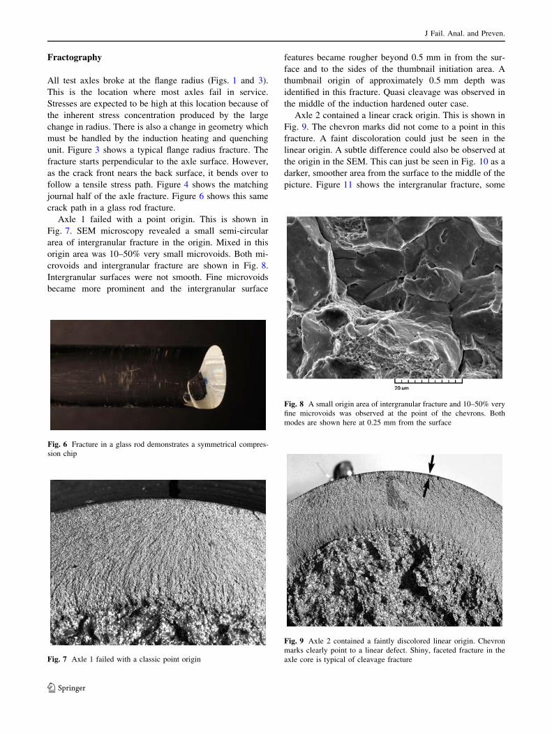
provided in Table 1. Figure 3 shows one of the semi-float
axle failures from the test. This shape of the fracture is
similar to the shape of most of the axle fractures which
have been observed in service. Figure 4 shows the
matching half of the test axle fracture. A wide range in the
loads at the rim required to cause failure can be seen even
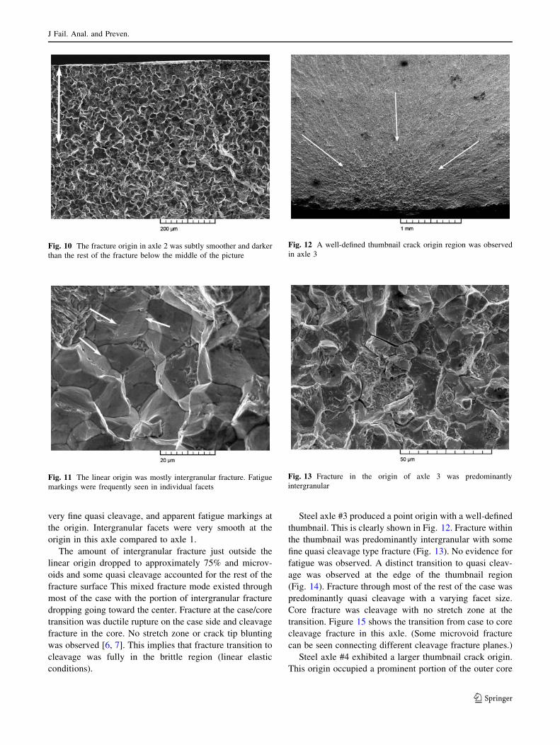
though the axles are nominally the same size. The button
dent results from the inboard end of the axle impacting the
differential pin (Fig. 1). The button dent in axle 2 is larger
Fig. 2 A schematic drawing of the semi-float axle test set up. The
stub axle test was similar except that no suspension was involved
Fig. 1 A schematic drawing of a semi-float axle is provided with
typical nomenclature
J Fail. Anal. and Preven.
123
than the one for axle 1 which had a higher failure load. This
larger dent is shown in Fig. 5. The difference in dent sizes
is probably related to the energy release conditions specific
to each axle test.
The leaf springs deflect substantially during side load-
ing. Spring deflection and axle bending constitute stored
elastic energy. This energy is suddenly released at the time
of fracture. The axle is restrained from being shot out of the
carrier by the C clip and a rebound effect produces a
dynamic load of the axle against the differential cross pin.
The stub axles were tested without springs and there were
no ball bearing dents on the journal surfaces after failure.
This is consistent with in-service failure because stub axle
failures in vehicles do contain ball bearing dents. (Vehicles
do have suspensions.) This observation supports the
hypothesis that dynamic rebound effect acts to produce the
bearing dents and helps to explain the double strike effect
wherein both button and bearing dents are found with super
imposed dents.
Roller bearing dents in axles 1 and 2 were measured but
not photographed shortly after testing. Examination of the
axles for preparation of the paper 5 years later failed to
reveal any evidence of bearing dents. Other documented
axles with photographs were also re-inspected at this time
with the same results, no dents. These dents are present in a
fully martensitic structure which appears to have a shape
memory effect [5] over a period of at least 5 years. Button
dents were still present when the end of the axles was not
hardened.
A wide variety of rim behavior was observed in these
tests and in other tests in which axle failure was not
achieved. Some axles could not be broken because of cast
aluminum rim failure. Aluminum rims tended to break as
the axle loads approached the normally expected failure
load levels for half ton truck axles. Standard steel rims
deformed severely while being loaded and the load
required to break the axles could not be achieved.
Table 1 Axle test results
Axle
test
Axle
type
Rim radius,
mm
Rim
alloy
Axle
diameter, mm
Failure
load, N
Button
dents, mm2Bearing
dents, mm2Rim
damage
Bent
axle
1 Semi-float 222 Al 41.1 61,110 17 6.4 Little Yes
2 Semi-float 222 Al 41.1 40,000 54 3.9 Little Yes
3 Stub 194 Steel 42.8 30,700 N/A None Little N/A
4 Stub 192 Steel 43.2 34,100 N/A None Deformed N/A
Fig. 3 The test axles failed in the flange radius
Fig. 4 The matching half of the fracture in Fig. 3 is shown
Fig. 5 The larger button dent on the tested semi-float axle
J Fail. Anal. and Preven.
123
Fractography
All test axles broke at the flange radius (Figs. 1 and 3).
This is the location where most axles fail in service.
Stresses are expected to be high at this location because of
the inherent stress concentration produced by the large
change in radius. There is also a change in geometry which
must be handled by the induction heating and quenching
unit. Figure 3 shows a typical flange radius fracture. The
fracture starts perpendicular to the axle surface. However,
as the crack front nears the back surface, it bends over to
follow a tensile stress path. Figure 4 shows the matching
journal half of the axle fracture. Figure 6 shows this same
crack path in a glass rod fracture.
Axle 1 failed with a point origin. This is shown in
Fig. 7. SEM microscopy revealed a small semi-circular
area of intergranular fracture in the origin. Mixed in this
origin area was 10–50% very small microvoids. Both mi-
crovoids and intergranular fracture are shown in Fig. 8.
Intergranular surfaces were not smooth. Fine microvoids
became more prominent and the intergranular surface
features became rougher beyond 0.5 mm in from the sur-
face and to the sides of the thumbnail initiation area. A
thumbnail origin of approximately 0.5 mm depth was
identified in this fracture. Quasi cleavage was observed in
the middle of the induction hardened outer case.
Axle 2 contained a linear crack origin. This is shown in
Fig. 9. The chevron marks did not come to a point in this
fracture. A faint discoloration could just be seen in the
linear origin. A subtle difference could also be observed at
the origin in the SEM. This can just be seen in Fig. 10 as a
darker, smoother area from the surface to the middle of the
picture. Figure 11 shows the intergranular fracture, some
Fig. 6 Fracture in a glass rod demonstrates a symmetrical compres-
sion chip
Fig. 7 Axle 1 failed with a classic point origin
Fig. 8 A small origin area of intergranular fracture and 10–50% very
fine microvoids was observed at the point of the chevrons. Both
modes are shown here at 0.25 mm from the surface
Fig. 9 Axle 2 contained a faintly discolored linear origin. Chevron
marks clearly point to a linear defect. Shiny, faceted fracture in the
axle core is typical of cleavage fracture
J Fail. Anal. and Preven.
123
very fine quasi cleavage, and apparent fatigue markings at
the origin. Intergranular facets were very smooth at the
origin in this axle compared to axle 1.
The amount of intergranular fracture just outside the
linear origin dropped to approximately 75% and microv-
oids and some quasi cleavage accounted for the rest of the
fracture surface This mixed fracture mode existed through
most of the case with the portion of intergranular fracture
dropping going toward the center. Fracture at the case/core
transition was ductile rupture on the case side and cleavage
fracture in the core. No stretch zone or crack tip blunting
was observed [6, 7]. This implies that fracture transition to
cleavage was fully in the brittle region (linear elastic
conditions).
Steel axle #3 produced a point origin with a well-defined
thumbnail. This is clearly shown in Fig. 12. Fracture within
the thumbnail was predominantly intergranular with some
fine quasi cleavage type fracture (Fig. 13). No evidence for
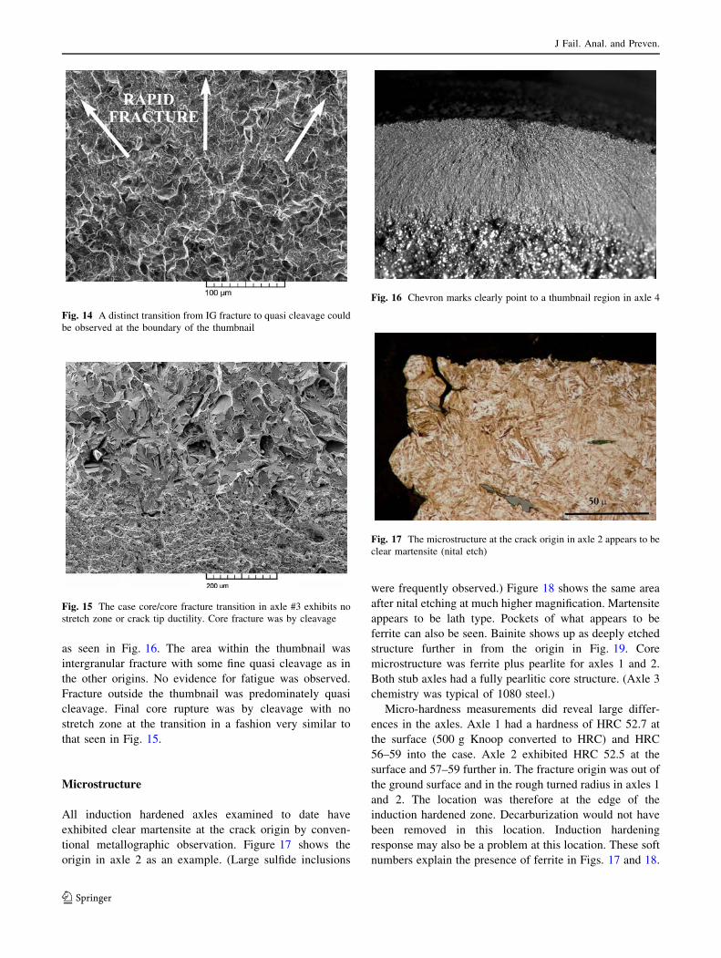
fatigue was observed. A distinct transition to quasi cleav-
age was observed at the edge of the thumbnail region
(Fig. 14). Fracture through most of the rest of the case was
predominantly quasi cleavage with a varying facet size.
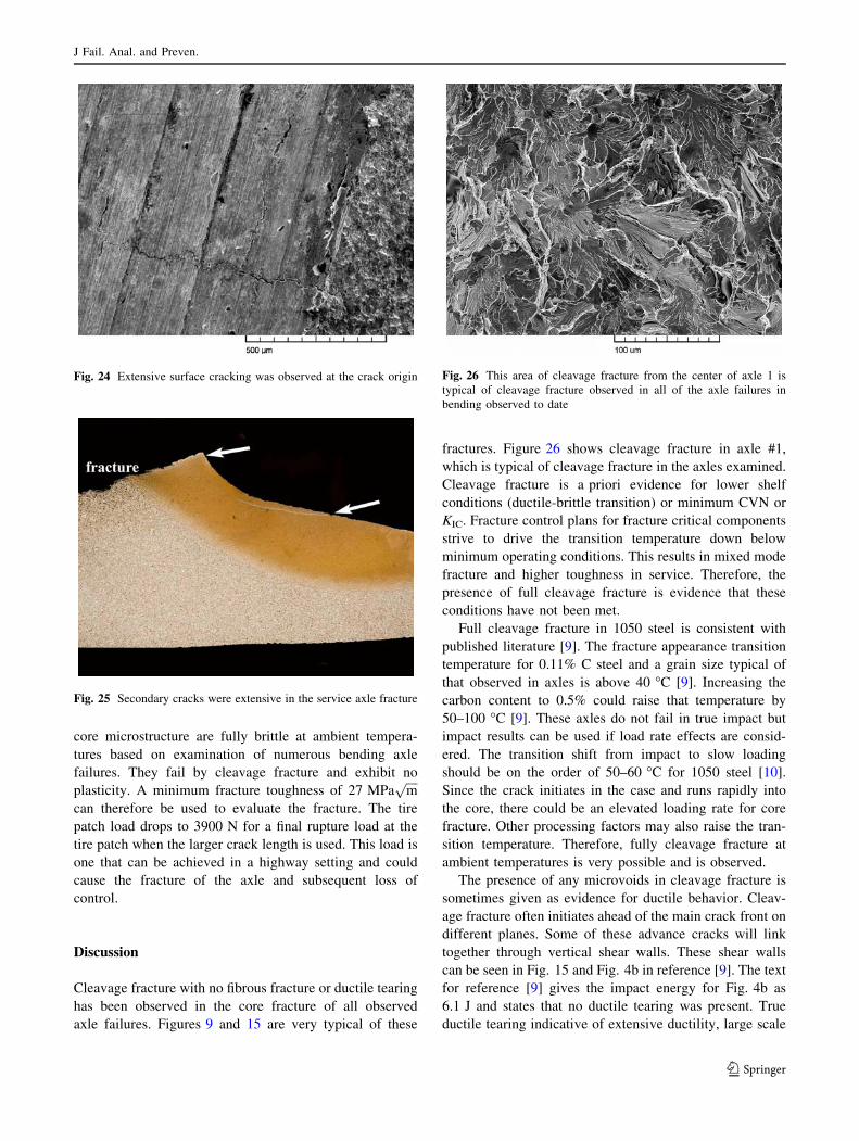
Core fracture was cleavage with no stretch zone at the
transition. Figure 15 shows the transition from case to core
cleavage fracture in this axle. (Some microvoid fracture
can be seen connecting different cleavage fracture planes.)
Steel axle #4 exhibited a larger thumbnail crack origin.
This origin occupied a prominent portion of the outer core
Fig. 10 The fracture origin in axle 2 was subtly smoother and darker
than the rest of the fracture below the middle of the picture
Fig. 11 The linear origin was mostly intergranular fracture. Fatigue
markings were frequently seen in individual facets
Fig. 12 A well-defined thumbnail crack origin region was observed
in axle 3
Fig. 13 Fracture in the origin of axle 3 was predominantly
intergranular
J Fail. Anal. and Preven.
123
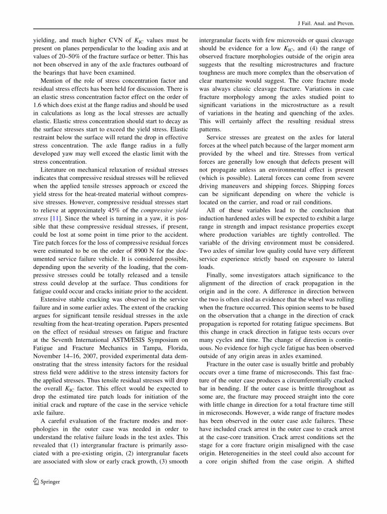
as seen in Fig. 16. The area within the thumbnail was
intergranular fracture with some fine quasi cleavage as in
the other origins. No evidence for fatigue was observed.
Fracture outside the thumbnail was predominately quasi
cleavage. Final core rupture was by cleavage with no
stretch zone at the transition in a fashion very similar to
that seen in Fig. 15.
Microstructure
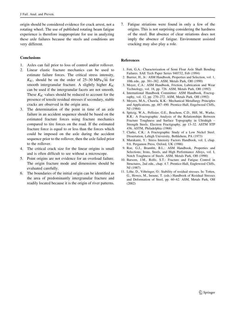
All induction hardened axles examined to date have
exhibited clear martensite at the crack origin by conven-
tional metallographic observation. Figure 17 shows the
origin in axle 2 as an example. (Large sulfide inclusions
were frequently observed.) Figure 18 shows the same area
after nital etching at much higher magnification. Martensite
appears to be lath type. Pockets of what appears to be
ferrite can also be seen. Bainite shows up as deeply etched
structure further in from the origin in Fig. 19. Core
microstructure was ferrite plus pearlite for axles 1 and 2.
Both stub axles had a fully pearlitic core structure. (Axle 3
chemistry was typical of 1080 steel.)
Micro-hardness measurements did reveal large differ-
ences in the axles. Axle 1 had a hardness of HRC 52.7 at
the surface (500 g Knoop converted to HRC) and HRC
56–59 into the case. Axle 2 exhibited HRC 52.5 at the
surface and 57–59 further in. The fracture origin was out of
the ground surface and in the rough turned radius in axles 1
and 2. The location was therefore at the edge of the
induction hardened zone. Decarburization would not have
been removed in this location. Induction hardening
response may also be a problem at this location. These soft
numbers explain the presence of ferrite in Figs. 17 and 18.
Fig. 14 A distinct transition from IG fracture to quasi cleavage could
be observed at the boundary of the thumbnail
Fig. 15 The case core/core fracture transition in axle #3 exhibits no
stretch zone or crack tip ductility. Core fracture was by cleavage
Fig. 16 Chevron marks clearly point to a thumbnail region in axle 4
Fig. 17 The microstructure at the crack origin in axle 2 appears to be
clear martensite (nital etch)
J Fail. Anal. and Preven.
123

Axle 3 had a hardness of HRC 61.5 at the origin surface.
Hardness values ranged 60–62 further in. This axle had a
carbon content of 0.746% and 0.943% Mn.
Axle 4 surface hardness was 59.8 HRC. Hardness values
ranged from 51.5 to 63.1 within 0.25 mm of the surface. A
chemical analysis was not obtained on this axle. The core
microstructure was 100% pearlite.
Stress Analysis
These four test axles provide a valuable basis with which
valid critical stress intensities, KIC, can be calculated. All
tests should be valid because the yield stress is high in
the outer case, there was no evidence of crack opening
displacement (CTOD) at the case/core transition, and the
dimensions were adequate to support plane strain behavior.
The results of the calculations are shown in Table 2. Stress
intensities for point origins were calculated using an
analysis for a semi-elliptical surface crack in bending by
Murakami [8].
Crack boundaries in point origin fractures were difficult
to measure accurately. Consequently several measurements
were made and averaged. Coloration on axle #2 served to
locate the initial crack boundary. Axles 3 and 4 were more
difficult to measure. The procedure for measuring point
origins involved marking the boundaries of river patterns,
changes in the origin area appearance, and changes in
fracture mode. The high stress axle #1 was the most dif-
ficult to measure. The higher estimated fracture toughness
and the fact that there was less intergranular fracture at the
origin is consistent with this axle’s higher performance.
Documented Service Failure
A documented axle failure on a half ton truck which did not
involve a rollover provides an example on how the failure
can be analyzed with the test axle data. The truck was
rounding a curve on a paved road when a witness saw the
truck lose its wheel and then lose control. The fracture
origin was in the rough turned flange radius. The axle was
bent. A large button dent is shown in Fig. 20 with clear
multiple aligned impacts. Roller dents on the journal along
with barber pole dark bands indicative of malfunctioning
induction hardening equipment can be seen in Fig. 21.
(Low hardness values have been observed in some of these
bands.) This vehicle had 20-in. (508 mm) decorative steel
wheels. The wheel with the broken axle exhibited scrape
marks from tucking under after axle fracture. No evidence
of lateral impact on the rim was observed.
Both halves of the axle fracture had been left outdoors
and allowed to rust. However, there was enough oil on the
inboard half of the axle still in the carrier such that cleaning
in a hot Alconox solution removed most of the rust. The
inboard half of the fracture had a point origin (Fig. 22).
Careful examination of the origin revealed an area
approximately 0.545 mm deep by 1.09 mm wide as shown
Fig. 18 The same area in Fig. 15 is shown at higher magnification
(nital etch). Some ferrite pockets can be seen
Fig. 19 The onset of bainite shows up as a deep etching structure in
axle 2 (nital etch)
Table 2 Fracture toughness calculations
Axle test Failure stress a, mm 2c, mm a/2c KIC, MPaffiffiffiffi
mp
1 2090 1.02 2.54 0.4 85
2 1290 0.125 ? 0 29.1
3 773 0.77 1.68 0.458 25.1
4 831 1.69 2.25 0.75 38.6
J Fail. Anal. and Preven.
123

in Fig. 23. Fracture within this area was predominantly
intergranular. The amount of fine quasi cleavage fracture
and dimple rupture were observed to increase significantly
out of this area.
Extensive secondary cracking was observed on the
rough turned OD surface at the crack origin and beneath
the fracture surface and OD surface. These cracks were
both axial and circumferential (Fig. 24). A cross section
through the crack origin shown in Fig. 25 shows a dif-
ferent view of the cracking. Large subsurface cracks are
pointed out by arrows. These cracks are good evidence
that there were no compressive residual stresses at the
flange radius.
The dark shadow in Fig. 22 demarking the outer case
and core fracture boundary points to a step or ridge
between the two. Most axle fractures (but not all) exhibit a
continuous fracture path across the transition with no evi-
dence of a stretch zone. Crack arrest in the core zone
occurred in this case.
Forces at the tire patch for this half ton truck for initi-
ation of fracture in the outer case were estimated to be
21,000 N using an estimated fracture toughness of
32 MPaffiffiffiffi
mp
. Force at the rim was 31,600 N for comparison
with the rest of the data. This load is high for a standard
truck tire but could be achieved with the higher perfor-
mance tires used on the larger rims on this truck at the
instant of tire sliding.
There was evidence for crack arrest at the case-core
transition. Type 1050 carbon steels with a ferrite-pearlite
Fig. 20 A large button dent was observed on the service axle
Fig. 21 Roller dents on the ground journal point to the origin. Journal
wear was more severe than that observed on most axles. Dark bands
in the rough turned axle are indicative of a malfunctioning induction
unit
Fig. 22 A point type origin can be seen in this fracture. A ridge
between the case and core fractures is accentuated by a shadow line
Fig. 23 A single point origin is marked by the arrows
J Fail. Anal. and Preven.
123
core microstructure are fully brittle at ambient tempera-
tures based on examination of numerous bending axle
failures. They fail by cleavage fracture and exhibit no
plasticity. A minimum fracture toughness of 27 MPaffiffiffiffi
mp
can therefore be used to evaluate the fracture. The tire
patch load drops to 3900 N for a final rupture load at the
tire patch when the larger crack length is used. This load is
one that can be achieved in a highway setting and could
cause the fracture of the axle and subsequent loss of
control.
Discussion
Cleavage fracture with no fibrous fracture or ductile tearing
has been observed in the core fracture of all observed
axle failures. Figures 9 and 15 are very typical of these
fractures. Figure 26 shows cleavage fracture in axle #1,
which is typical of cleavage fracture in the axles examined.
Cleavage fracture is a priori evidence for lower shelf
conditions (ductile-brittle transition) or minimum CVN or
KIC. Fracture control plans for fracture critical components
strive to drive the transition temperature down below
minimum operating conditions. This results in mixed mode
fracture and higher toughness in service. Therefore, the
presence of full cleavage fracture is evidence that these
conditions have not been met.
Full cleavage fracture in 1050 steel is consistent with
published literature [9]. The fracture appearance transition
temperature for 0.11% C steel and a grain size typical of
that observed in axles is above 40 �C [9]. Increasing the
carbon content to 0.5% could raise that temperature by
50–100 �C [9]. These axles do not fail in true impact but
impact results can be used if load rate effects are consid-
ered. The transition shift from impact to slow loading
should be on the order of 50–60 �C for 1050 steel [10].
Since the crack initiates in the case and runs rapidly into
the core, there could be an elevated loading rate for core
fracture. Other processing factors may also raise the tran-
sition temperature. Therefore, fully cleavage fracture at
ambient temperatures is very possible and is observed.
The presence of any microvoids in cleavage fracture is
sometimes given as evidence for ductile behavior. Cleav-
age fracture often initiates ahead of the main crack front on
different planes. Some of these advance cracks will link
together through vertical shear walls. These shear walls
can be seen in Fig. 15 and Fig. 4b in reference [9]. The text
for reference [9] gives the impact energy for Fig. 4b as
6.1 J and states that no ductile tearing was present. True
ductile tearing indicative of extensive ductility, large scale
Fig. 24 Extensive surface cracking was observed at the crack origin
Fig. 25 Secondary cracks were extensive in the service axle fracture
Fig. 26 This area of cleavage fracture from the center of axle 1 is
typical of cleavage fracture observed in all of the axle failures in
bending observed to date
J Fail. Anal. and Preven.
123
yielding, and much higher CVN of KIC values must be
present on planes perpendicular to the loading axis and at
values of 20–50% of the fracture surface or better. This has
not been observed in any of the axle fractures outboard of
the bearings that have been examined.
Mention of the role of stress concentration factor and
residual stress effects has been held for discussion. There is
an elastic stress concentration factor effect on the order of
1.6 which does exist at the flange radius and should be used
in calculations as long as the local stresses are actually
elastic. Elastic stress concentration should start to decay as
the surface stresses start to exceed the yield stress. Elastic
restraint below the surface will retard the drop in effective
stress concentration. The axle flange radius in a fully
developed yaw may well exceed the elastic limit with the
stress concentration.
Literature on mechanical relaxation of residual stresses
indicates that compressive residual stresses will be relieved
when the applied tensile stresses approach or exceed the
yield stress for the heat-treated material without compres-
sive stresses. However, compressive residual stresses start
to relieve at approximately 45% of the compressive yield
stress [11]. Since the wheel is turning in a yaw, it is pos-
sible that these compressive residual stresses, if present,
could be lost at some point in time prior to the accident.
Tire patch forces for the loss of compressive residual forces
were estimated to be on the order of 8900 N for the doc-
umented service failure vehicle. It is considered possible,
depending upon the severity of the loading, that the com-
pressive stresses could be totally released and a tensile
stress could develop at the surface. Thus conditions for
fatigue could occur and cracks initiate prior to the accident.
Extensive stable cracking was observed in the service
failure and in some earlier axles. The extent of the cracking
argues for significant tensile residual stresses in the axle
resulting from the heat-treating operation. Papers presented
on the effect of residual stresses on fatigue and fracture
at the Seventh International ASTM/ESIS Symposium on
Fatigue and Fracture Mechanics in Tampa, Florida,
November 14–16, 2007, provided experimental data dem-
onstrating that the stress intensity factors for the residual
stress field were additive to the stress intensity factors for
the applied stresses. Thus tensile residual stresses will drop
the overall KIC factor. This effect would be expected to
drop the estimated tire patch loads for initiation of the
initial crack and rupture of the case in the service vehicle
axle failure.
A careful evaluation of the fracture modes and mor-
phologies in the outer case was needed in order to
understand the relative failure loads in the test axles. This
revealed that (1) intergranular fracture is primarily asso-
ciated with a pre-existing origin, (2) intergranular facets
are associated with slow or early crack growth, (3) smooth
intergranular facets with few microvoids or quasi cleavage
should be evidence for a low KIC, and (4) the range of
observed fracture morphologies outside of the origin area
suggests that the resulting microstructures and fracture
toughness are much more complex than the observation of
clear martensite would suggest. The core fracture mode
was always classic cleavage fracture. Variations in case
fracture morphology among the axles studied point to
significant variations in the microstructure as a result
of variations in the heating and quenching of the axles.
This will certainly affect the resulting residual stress
patterns.
Service stresses are greatest on the axles for lateral
forces at the wheel patch because of the larger moment arm
provided by the wheel and tire. Stresses from vertical
forces are generally low enough that defects present will
not propagate unless an environmental effect is present
(which is possible). Lateral forces can come from severe
driving maneuvers and shipping forces. Shipping forces
can be significant depending on where the vehicle is
located on the carrier, and road or rail conditions.
All of these variables lead to the conclusion that
induction hardened axles will be expected to exhibit a large
range in strength and impact resistance properties except
where production variables are tightly controlled. The
variable of the driving environment must be considered.
Two axles of similar low quality could have very different
service experience strictly based on exposure to lateral
loads.
Finally, some investigators attach significance to the
alignment of the direction of crack propagation in the
origin and in the core. A difference in direction between
the two is often cited as evidence that the wheel was rolling
when the fracture occurred. This opinion seems to be based
on the observation that a change in the direction of crack
propagation is reported for rotating fatigue specimens. But
this change in crack direction in fatigue tests occurs over
many cycles and time. The change of direction is contin-
uous. No evidence for high cycle fatigue has been observed
outside of any origin areas in axles examined.
Fracture in the outer case is usually brittle and probably
occurs over a time frame of microseconds. This fast frac-
ture of the outer case produces a circumferentially cracked
bar in bending. If the outer case is brittle throughout as
some are, the fracture may proceed straight into the core
with little change in direction for a total fracture time still
in microseconds. However, a wide range of fracture modes
has been observed in the outer case axle failures. These
have included crack arrest in the outer case to crack arrest
at the case-core transition. Crack arrest conditions set the
stage for a core fracture origin misaligned with the case
origin. Heterogeneities in the steel could also account for
a core origin shifted from the case origin. A shifted
J Fail. Anal. and Preven.
123
origin should be considered evidence for crack arrest, not a
rotating wheel. The use of published rotating beam fatigue
experience is therefore inappropriate for use in analyzing
these axle failures because the steels and conditions are
very different.
Conclusions
1. Axles can fail prior to loss of control and/or rollover.
2. Linear elastic fracture mechanics can be used to
estimate failure forces. The critical stress intensity,
KIC, should be on the order of 25–30 MPaffiffiffiffi
mp
for
smooth intergranular fracture. A slightly higher KIC
can be used if the intergranular facets are not smooth.
These KIC values should be reduced to account for the
presence of tensile residual stresses if secondary, stable
cracks are observed in the origin area.
3. The determination of the point in time of an axle
failure in an accident sequence should be based on the
estimated fracture forces using fracture mechanics
compared to tire forces on the road. If the estimated
fracture force is equal to or less than the forces which
could be imposed on the axle during the accident
sequence prior to the rollover, then the axle failed prior
to the rollover.
4. The critical crack size for the linear origins is small
and is often difficult to see without a microscope.
5. Point origins are not evidence for an overload failure.
The origin fracture mode and dimensions should be
evaluated carefully.
6. The boundaries of the initial origin can be identified as
the area of predominantly intergranular fracture and
readily located because it is the origin of river patterns.
7. Fatigue striations were found in only a few of the
origins. This is not surprising considering the hardness
of the steel. But absence of clear striations does not
imply the absence of fatigue. Environment assisted
cracking may also play a role.
References
1. Fett, G.A.: Characterization of Semi Float Axle Shaft Bending
Failures. SAE Tech Paper Series 940732, Feb (1994)
2. Burrier, H., Jr.: ASM Handbook, Properties and Selection, vol. 1,
10th edn., pp. 381–382. ASM, Metals Park, OH (1990)
3. Moyer, C.A.: ASM Handbook, Friction, Lubrication and Wear
Technology, vol. 18, pp. 726. ASM, Metals Park, OH (1992)
4. International Handbook Committee: ASM Handbook, Fractog-
raphy, vol. 12, pp. 270–272. ASM, Metals Park, OH (1992)
5. Meyers, M.A., Chawla, K.K.: Mechanical Metallurgy Principles
and Applications, pp. 487–490. Prentice-Hall, Engelwood Cliffs,
NJ (1984)
6. Spitzig, W.A., Pellisier, G.E., Beachem, C.D., Hill, M., Warke,
R.R.: A Fractographic Analysis of the Relationships Between
Fracture Toughness and Surface Topography in Ultrahigh –
Strength Steels. Electron Fractigraphy, pp 13–32. ASTM STP
436, ASTM, Philadelphia (1968)
7. Clarke, C.K.: A Fractographic Study of a Low Nickel Steel.
Dissertation, Lehigh University, Bethlehem, PA (1973)
8. Murakami, Y.: Stress Intensity Factors Handbook, vol. I, chap.
9.6. Pergamon Press, Oxford, UK (1986)
9. Roe, G.J., Bramfitt, B.L.: ASM Handbook, Properties and
Selections; Irons, Steels, and High Performance Alloys, vol. I,
Notch Toughness of Steels. ASM, Metals Park, OH (1990)
10. Barsom, J.M., Rolfe, S.T.: Fracture and Fatigue Control in
Structures, 2nd edn., chap. 4.7. Prentice-Hall, Englewood Cliffs,
NJ (1987)
11. Lohe, D., Vohringer, O.: Stability of residual stresses. In: Totten,
G., Howes, M., Inoune, T. (eds.) Handbook of Residual Stresses
and Deformation of Steel, pp. 60–62. ASM, Metals Park, OH
(2002)
J Fail. Anal. and Preven.
123