Embed Size (px)
Citation preview

ERJ Engineering Research Journal
Faculty of Engineering Menoufia University
Engineering Research Journal, Vol. 43, No. 1, January 2020, PP: 41-50
© Faculty of Engineering, Menoufia University, Egypt
41
Failure Analysis of an Exploded Large-Capacity Liquid Storage
Tank Using Finite Element Analysis
Mahmoud Abo-Elkhier, Kamel Muhammad
Department of Production Engineering and Mechanical Design, Menoufia
University, Shebien El-Koum, Egypt
E-mail: [email protected]
ABSTRACT:
In case of liquid storage tank has been designed regardless of international standards and there is
little interest with its operating conditions, it may lead to fully or partially failure. This paper has
studied a failure of Toluene storage tanks with different capacities. Toluene is a liquid aromatic
hydrocarbon C7H8 which is toxic, flammable and may cause boiled liquid expanded vapor
explosions (BLEVE). Failure analysis was performed to determine the root causes of toluene
storage tank failure as well as corrosion influence. Axisymmetric finite Element analysis
(FEA) was performed for fillet welding of tank roof and top shell zone to develop a relation
between weld electrode size and tank diameter at each type of weld electrode to determine the
main framework of roof to top shell welding process. Also, to develop a relation between tank
diameter and maximum stresses that resulted at every amount of vapor pressure according to
maximum von-Mises stress theory. The optimum roof to top shell welding size is obtained through
the circumference welding path. The results of analysis allowed us to redesign the tank according
to API 650 and to express the recommendations for toluene storage tanks operation.
:البحث ملخص
إهاسها إنى قذ ؤدي رنكفئ ، أو دساست ظشوف تشغهها انعاش انذونت انسىائم بذو الاهتاو ب تخض اثتصى خضا إرا تى
هذسوكشبى . انطىنى هى سائما انبحجانطىنى بسعاث يختهفت خلال هز خضاسىف تى دساست إهاس .كها أو رضئا
عضىي، ساو و قابم نلإشتعال وقذ ؤدي إن حذوث يا س بظاهشة الإفزاساث اناتزت ي ضغظ انغاص انتذد ي غها
تى إرشاء سبا إهاس انخضا انشئست بالإضافت إن تثحش انتككم.عط يؤششاث واضحت لأتحهم الإهاس انسائم انعضىي.
لإستتاد انعلاقت ب حزى تحهم انعاصش انحذدة انحىسي نطقت انهحاو يا ب غطاء انخضا و انزضء انعهىي الأخش يه
لإستتاد علاقت ب قطش انخضا وأقص إرهاداث ارت ع انهحاو وقطش انخضا عذ كم ىع ي أىاع أقطا انهحاو. وأضا
ضغىط انبخاس اناتزت ع تذد انسائم انعضىي. تى تحذذ افضم حزى نساس انهحاو يا ب غطاء انخضا وأعه يطقت يه.
انسىائم وإبشاص أهى الأيشك انخاص بتصى خضااث تخض تائذ انبحج ك إستخذايها لإعادة تصى انخضا وفقا نهكىد
الإسشاداث و انتىصاث نتشغم يخم هزا انىع ي انخضااث.
Keywords: BLEVE; Toluene storage tank, Failure analysis, Finite element analysis, Axisymmetric
stress analysis.
1. INTRODUCTION
Liquid storage tank is the important equipment
that is used in many industrial fields such as
chemical, petroleum, food, and pharmaceutical…etc.
industries. Many experimental and theoretical studies
were made to investigate the failure causes of liquid
storage tanks. Also, many investigations were
developed by using three dimensions simulations to
study the resulting stresses during operation. The
study of failure analysis of aromatic storage tanks
using numerical and three dimensions stress analysis
with applying of BLEVE and thermo dynamics
theories has been given little interest. Trebuna, et al.
[1] studied failure of a hot water storage tank. The
plant had two tanks which are used for storing hot
water, one of them has been failed. During operation,
the failed one was damaged by collapse of its roof.
Analytical, numerical and experimental analysis of
possible failure reasons were per-formed but it had
not included macroscopic examinations for studying
the causes of welding failure. They studied stresses in
the tank during its operation. The research did not
include parametric study of axisymmetric welding
simulation between tank welded failed parts. Possible
causes of Initiation of plastic deformation in the
Containers Used in Food Industry have been studied
in ref. [2]. During operation, the containers may be
exposed to overloading. Also, their study did not deal
with welding, corrosion and vapor pressures effects
on storage tank. This has been previously assessed
only to a very limited extent because the relation

Mahmoud Abo-Elkhier, Kamel Muhammad" Failure Analysis of an Exploded Large-Capac…"
Engineering Research Journal, Menoufia University, Vol. 43, No. 1, January 2020 42
between welding electrode strength and the affected
stresses had not been included during this research.
Yanga, et al. [3] used the finite element method to
investigate the mechanical behavior of Al/Al-Mg
composites for the design of tank cars under actual
measuring loads. They used of
Aluminum/Aluminum-Magnesium (Al/Al-Mg)
alloys to form laminated composites to solve the
problems associated with the low corrosion
resistance and strength of tank car bodies. A finite
element analysis was used to simulate the tensile
tests of the Al/Al-Mg laminated composites. Previous
studies of finite element analysis of tensile tests
cannot be considered as conclusive because it had not
been included a welding finite element simulation.
Cirimelloa, et al. [4] have investigated a 2000 m3
washer tank at a crude oil treatment plant suffered a
structural collapse, involving total loss of integrity.
Due to the large initial leakage flow, the containment
enclosure wall could not hold the spilled mixture of
water and crude oil. Only a few works in literature
demonstrate the root cause of fracture and it had not
shown the start of initial crack. Focusing on welding
paths of tank bottom and bottom shell had a little
interest. It did not study the relationship between
welding strength and loads. The graphs of welding
electrode size and position along weld seam distance
had a little interest which is a very important tool to
avoid this type of catastrophic failure.
Yao, et al. [5] have calculated the stresses of
spherical tank and displacement of column bases by
finite element methods, considering the uneven
gravity loads on support columns which caused by
manufacturing and setting errors. It did not focus on
the weak point of tank design such as bottom-shell
design and roof-shell design. It also did not pay
attention to the corrosion allowance as a very
important parameter during design steps. Welding
loads had not been included during the research.
The aim of this paper is to analyze the stresses at the
moment of the failure of a vertical liquid storage tank
of capacity 350 m3. The failure leads to top shell-roof
separation. Also, a relation between weld electrode
size and tank diameter at each type of weld electrode
is developed to determine the main framework of
roof to top shell welding process. A relation between
tank diameter and maximum stresses that resulted at
every amount of vapor pressure according to
maximum von-Mises stress theory is obtained. The
optimum roof to top shell welding size through the
circumference of welding path is predicted and
propose the corrective actions for safely operation of
the liquid toluene storage tanks. The tank had been
constructed since 1989 (approximately 30 years old)
was used to store toluene at the liquid state Fig. 1 (a).
Two gear pumps (Worthington Simpson Ltd 50 CPG
250) with the power of 22 KW and flow rate was 50
cubic meter/hour at 5 bar were used to charge the
tank with a liquid toluene. The pumps were at the
level of 225 mm from the bottom of the tank. There
were many steam pipe lines around the tank and the
temperature was 50° C outside the tank. The roof of
the tank started to separate from the top shell after 10
minutes of toluene liquid charging as shown in Fig. 1
(b).
(a)
(b)
Fig. 1. (a) View of the tanks (b) View of the failed
roof and top shell.
2. STORAGE TANK GEOMETRICAL DATA
(a) Shell specifications
The toluene storage tank is made of 5 shells. Every
shell consists of four sheet plates butt welded
together as shown in Fig. 2. The bottom three shells
are of the same height 1500 mm and thickness 8 mm
while, the higher two shells are of the same height
1250 mm and thickness 6 mm. Tank roof is cone type
with thickness 5 mm and height of 500 mm.
Manufacture’s technical drawings mentioned that the
tank is made of St-37 according to DIN (Deutsches
Institut für Normung)which means (German Institute
of Standardization standard).
(b) Roof specifications
Roof is constructed from sheet plates with thickness
of 5 mm are intermittent chain welded with four
trusses. Roof truss is constructed from steel 37 L
with dimensions 50×50×5 mm profile as shown in
Fig. 3. Roof trusses are welded to the cylinder with a
height of 500 mm and diameter of 200 mm at the
center of tank roof.

Mahmoud Abo-Elkhier, Kamel Muhammad" Failure Analysis of an Exploded Large-Capac…"
Engineering Research Journal, Menoufia University, Vol. 43, No. 1, January 2020 43
Fig. 2. Dimensions of the tank
Fig. 3. Dimensions of roof truss.
(c) Tank bottom specifications Tank bottom is consisted of bottom plate and annular
plate. Bottom plate and annular plate are sheet metal
plates which are overlap welded together with the
thickness of 6 and 8 mm. Bottom shell and bottom
plates are welded to annular plates which are
supported to the soil by concrete. Specifications and
dimensions of tank bottom are shown in Fig. 4.
Fig. 4. Fabrication of the tank bottom.
3. TOLUENE PHYSICAL DATA AND PRESSURE-TEMPERATURE DIAGRAM. Toluene physical properties should be studied to determine the minimum temperature which the toluene should not be exceeded to avoid overpressure that causes tank failure. Toluene phase diagram shown in Fig. 5 illustrates its behavior with temperature and pressure changing. It also shows the saturation pressure with changes in temperature. Vapor pressures that resulted at boiling, upper superheat limit and lower superheat limit temperatures will be accurately calculated using Antoine equation to be used in the axisymmetric finite element analysis of the failed part of the tank. For more details about toluene chemical and physical properties see Ref. [7]. 4. FAILURE INVESTIGATION AND CORROSION RATE EXPERIMENTAL WORK (a) Tension test Tensile tests were performed using three standard tensile specimens with thickness T = 6 mm. The specimens were selected from undamaged shell of the tank material. Specimens were prepared according to ASTM E 646-98 standard. The obtained mechanical properties and chemical compositions are shown in Tables 1 and 2.

Mahmoud Abo-Elkhier, Kamel Muhammad" Failure Analysis of an Exploded Large-Capac…"
Engineering Research Journal, Menoufia University, Vol. 43, No. 1, January 2020 44
Fig. 5. Toluene phase diagram [6].
Table 1 Mechanical properties of tank material (ST37-2)
Elongation, min, δ, % Yield point, min, KSI [MPa]
Elasticity Modulus [MPa]
Tensile strength, KSI [MPa]
Steel grade
25 34 [235] [210000] 52 - 67 [360 - 460] ST37-2 Table 2 Chemical compositions of ST37-2
Nitrogen, max, %
Sulfur, max, %
Phosphorus, max, %
Manganese, %
Silicon, %
Carbon, max, %
Steel grade
0.011 0.050 0.050 0.35 - 0.75 0.15 - 0.35
0.20 ST37-2
(b) Macroscopic examination of welding specimens Two specimens have been cut from the welding; one in the horizontal and the other is the vertical direction as shown in Fig. 6 (a) and (b). Horizontal welding specimen had been collected from circumference welding path between the roof and top shell while, the vertical one had been collected from the weld between the plates of the top shell. Specimens were polished and etched for metallographic examination. It is noticed that there is a misalignment between two base metals of vertical welding of top shell segments which converts any small amount of direct load into shear load.
(a)
(b)
Fig. 6. (a) Horizontal welding specimen (Roof to top
shell weldment) (b) Vertical welding specimen (Top
shell segments weldment).
When the primary fracture has been damaged or corroded to such a degree that most of the information about the cause of fracture is obliterated, it is desirable to examine any secondary cracks to expose their fracture surfaces for examination [8]. High power optical microscope with magnification of 25 time is used for detailed examination of fractured surfaces. It detects the direction of cracks and the origin of failure in the form of macrographs that had small resolution and high depth of field.
Mahmoud Abo-Elkhier, Kamel Muhammad" Failure Analysis of an Exploded Large-Capac…"
Engineering Research Journal, Menoufia University, Vol. 43, No. 1, January 2020 45
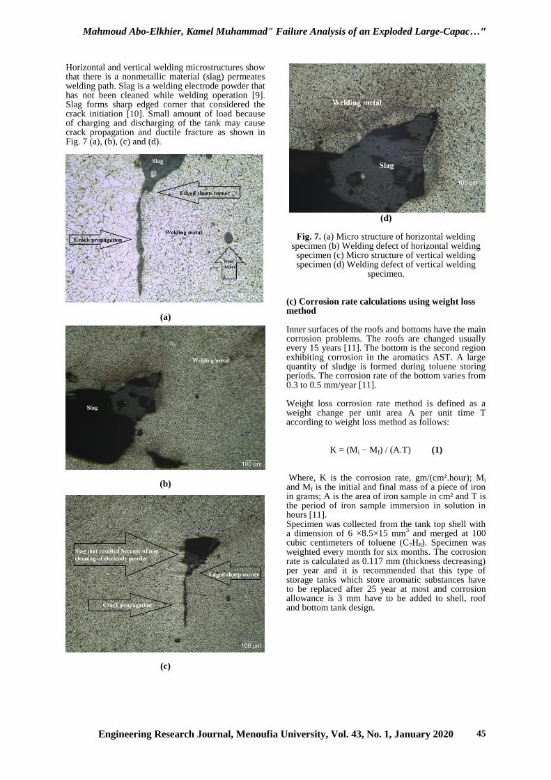
Horizontal and vertical welding microstructures show that there is a nonmetallic material (slag) permeates welding path. Slag is a welding electrode powder that has not been cleaned while welding operation [9]. Slag forms sharp edged corner that considered the crack initiation [10]. Small amount of load because of charging and discharging of the tank may cause crack propagation and ductile fracture as shown in Fig. 7 (a), (b), (c) and (d).
(a)
(b)
(c)
(d)
Fig. 7. (a) Micro structure of horizontal welding specimen (b) Welding defect of horizontal welding
specimen (c) Micro structure of vertical welding specimen (d) Welding defect of vertical welding
specimen.
(c) Corrosion rate calculations using weight loss method Inner surfaces of the roofs and bottoms have the main corrosion problems. The roofs are changed usually every 15 years [11]. The bottom is the second region exhibiting corrosion in the aromatics AST. A large quantity of sludge is formed during toluene storing periods. The corrosion rate of the bottom varies from 0.3 to 0.5 mm/year [11]. Weight loss corrosion rate method is defined as a weight change per unit area A per unit time T according to weight loss method as follows:
K = (Mi − Mf) / (A.T) (1) Where, K is the corrosion rate, gm/(cm².hour); Mi and Mf is the initial and final mass of a piece of iron in grams; A is the area of iron sample in cm² and T is the period of iron sample immersion in solution in hours [11]. Specimen was collected from the tank top shell with a dimension of 6 ×8.5×15 mm
3 and merged at 100
cubic centimeters of toluene (C7H8). Specimen was weighted every month for six months. The corrosion rate is calculated as 0.117 mm (thickness decreasing) per year and it is recommended that this type of storage tanks which store aromatic substances have to be replaced after 25 year at most and corrosion allowance is 3 mm have to be added to shell, roof and bottom tank design.
Mahmoud Abo-Elkhier, Kamel Muhammad" Failure Analysis of an Exploded Large-Capac…"
Engineering Research Journal, Menoufia University, Vol. 43, No. 1, January 2020 46
5. BOILED LIQUID EXPANDING VAPOR EPLOSION (BLEVE) AND ANTOINE EQUATION (a) BLEVE definition and mechanism The term BLEVE was defined as a failure of a major liquid filled container into two or multiple pieces at a moment when the temperature of the contained liquid is well above its boiling point at normal atmospheric pressure [12]. Berg et al. [13] suggest that the definition of a BLEVE should not include a possible subsequent generation of a fireball, but comprise only the explosive rupture of the pressure vessel and the subsequent flash evaporation of its superheated liquid content. So, the higher the liquid temperature is at the moment of tank rupture, the more severe will be the accident. The role of superheat limit temperature (SLT) of the liquid in BLEVE development was extensively reviewed by Abbasi and Abbasi [14]. So, there is a relation between crack and crack propagation through the liquid storage tank shell and the occurrence of BLEVE. The first tear or crack may or may not propagate straight away to a sufficient size to cause a BLEVE instantaneously. In some cases, an initial tear or crack that is too small to initiate a BLEVE directly, may restart propagation again after some time and increase to the size required to cause a BLEVE. According to research conducted by Birk and Cunningham [15]. Superheat Limit Temperature (SLT) is not an absolute lower temperature limit for a BLEVE to occur. BLEVEs can occur even at temperatures significantly below the SLT [15]. (b) Antoine equation and calculating of toluene vapor pressure. The Antoine equation could be used to determine the relation between aromatics substances vapor pressure and temperature. The Clausius–Clapeyron relation is the source of the Antoine equation as follows [16]:
Log10 P=(A-B)/(C+T) (2) where P is the saturated vapor pressure in kilopascals (kPa), T is the temperature in kelvins and A, B, and C are Antoine constants. In most cases the Antoine constants are for the liquid, but in some cases the constants are for the solid. If the temperature range = 383 to 445 (Kelvin) the constants will be A= 6.12072, B= 1374.901, and C= -49.657 and when the temperature range = 440 to 531 (Kelvin) the constants will be A= 6.40851, B= 1615.834, and C= -15.897. Vapor pressure at boiling temperature of toluene is equal to 0.10197 MPa and it is increased to 1.1956 MPa at SLT (lower) and to 1.86894 MPa at SLT (upper).
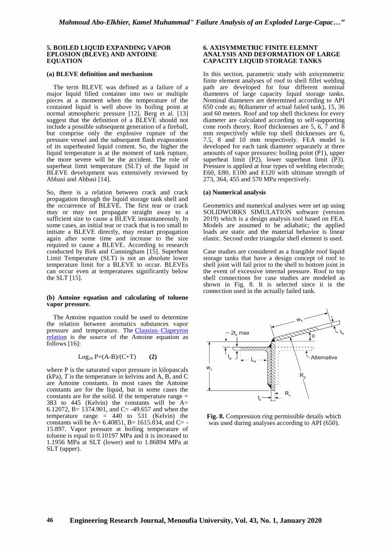
6. AXISYMMETRIC FINITE ELEMNT ANALYSIS AND DEFORMATION OF LARGE CAPACITY LIQUID STORAGE TANKS In this section, parametric study with axisymmetric finite element analyses of roof to shell fillet welding path are developed for four different nominal diameters of large capacity liquid storage tanks. Nominal diameters are determined according to API 650 code as; 8(diameter of actual failed tank), 15, 36 and 60 meters. Roof and top shell thickness for every diameter are calculated according to self-supporting cone roofs theory. Roof thicknesses are 5, 6, 7 and 8 mm respectively while top shell thicknesses are 6, 7.5, 8 and 10 mm respectively. FEA model is developed for each tank diameter separately at three amounts of vapor pressures: boiling point (P1), upper superheat limit (P2), lower superheat limit (P3). Pressure is applied at four types of welding electrode; E60, E80, E100 and E120 with ultimate strength of 273, 364, 455 and 570 MPa respectively. (a) Numerical analysis Geometrics and numerical analyses were set up using SOLIDWORKS SIMULATION software (version 2019) which is a design analysis tool based on FEA. Models are assumed to be adiabatic; the applied loads are static and the material behavior is linear elastic. Second order triangular shell element is used. Case studies are considered as a frangible roof liquid storage tanks that have a design concept of roof to shell joint will fail prior to the shell to bottom joint in the event of excessive internal pressure. Roof to top shell connections for case studies are modeled as shown in Fig. 8. It is selected since it is the connection used in the actually failed tank.
Fig. 8. Compression ring permissible details which was used during analyses according to API (650).
Mahmoud Abo-Elkhier, Kamel Muhammad" Failure Analysis of an Exploded Large-Capac…"
Engineering Research Journal, Menoufia University, Vol. 43, No. 1, January 2020 47
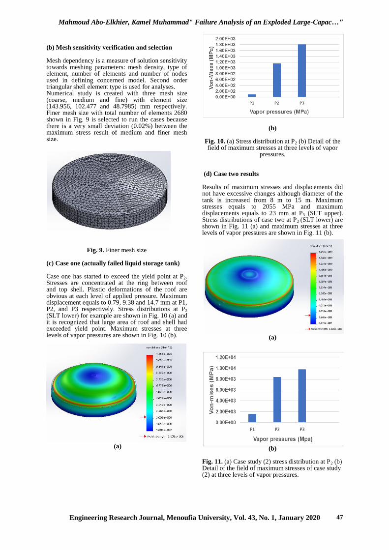
(b) Mesh sensitivity verification and selection Mesh dependency is a measure of solution sensitivity towards meshing parameters: mesh density, type of element, number of elements and number of nodes used in defining concerned model. Second order triangular shell element type is used for analyses. Numerical study is created with three mesh size (coarse, medium and fine) with element size (143.956, 102.477 and 48.7985) mm respectively. Finer mesh size with total number of elements 2680 shown in Fig. 9 is selected to run the cases because there is a very small deviation (0.02%) between the maximum stress result of medium and finer mesh size.
Fig. 9. Finer mesh size (c) Case one (actually failed liquid storage tank) Case one has started to exceed the yield point at P2. Stresses are concentrated at the ring between roof and top shell. Plastic deformations of the roof are obvious at each level of applied pressure. Maximum displacement equals to 0.79, 9.38 and 14.7 mm at P1, P2, and P3 respectively. Stress distributions at P2
(SLT lower) for example are shown in Fig. 10 (a) and it is recognized that large area of roof and shell had exceeded yield point. Maximum stresses at three levels of vapor pressures are shown in Fig. 10 (b).
(a)
(b)
Fig. 10. (a) Stress distribution at P2 (b) Detail of the field of maximum stresses at three levels of vapor
pressures.
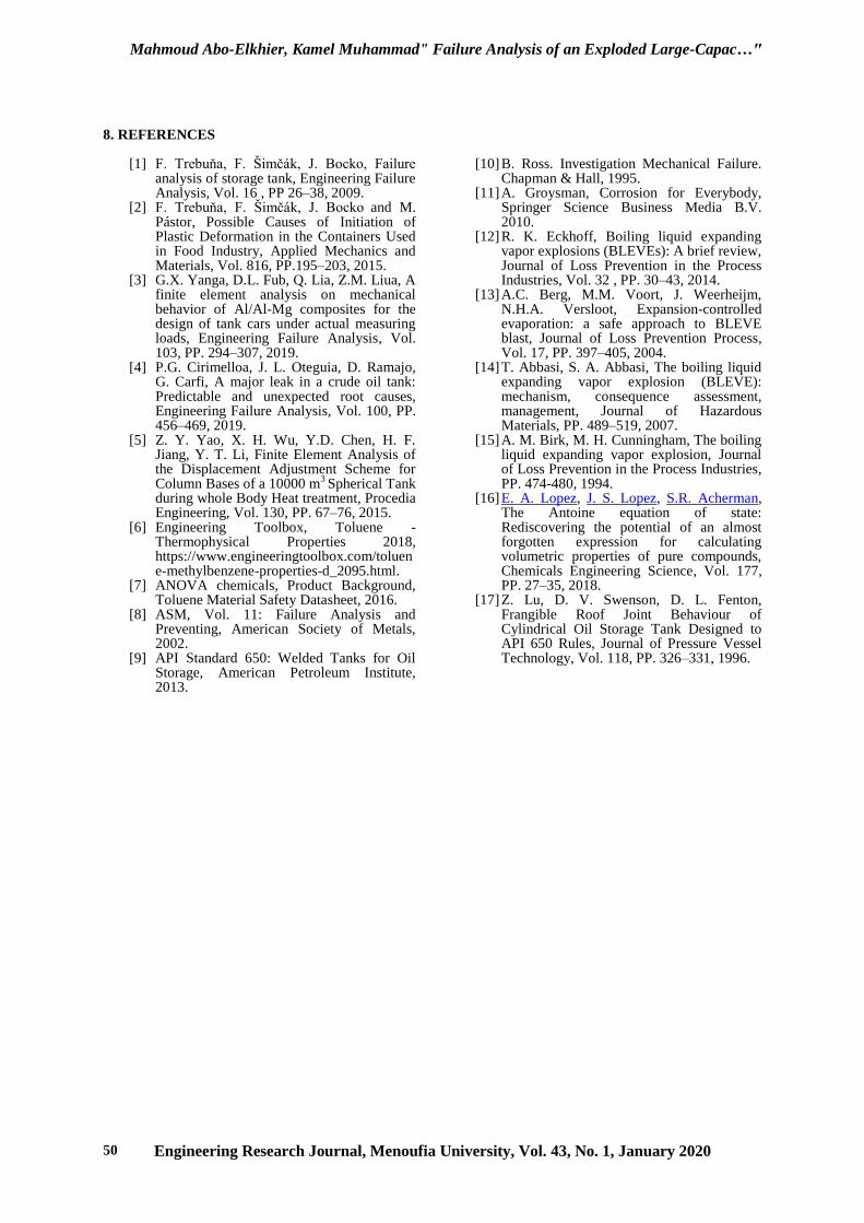
(d) Case two results Results of maximum stresses and displacements did not have excessive changes although diameter of the tank is increased from 8 m to 15 m. Maximum stresses equals to 2055 MPa and maximum displacements equals to 23 mm at P3 (SLT upper). Stress distributions of case two at P2 (SLT lower) are shown in Fig. 11 (a) and maximum stresses at three levels of vapor pressures are shown in Fig. 11 (b).
(a)
(b)
Fig. 11. (a) Case study (2) stress distribution at P2 (b) Detail of the field of maximum stresses of case study (2) at three levels of vapor pressures.

Mahmoud Abo-Elkhier, Kamel Muhammad" Failure Analysis of an Exploded Large-Capac…"
Engineering Research Journal, Menoufia University, Vol. 43, No. 1, January 2020 48
(e) Case three results Results of maximum stresses and displacements have multiplied because of volume increasing. It is recognized that large area of roof to shell plates are subjected to high stresses at low levels of vapor pressures in addition to high stress concentrations at welding zone. At high pressure value for this liquid storage tank volume, this type of failure could have large deformation. It could exceed 120 mm at most roof area. Fig. 12 (a) shows stress distributions at P2 (SLT lower) and maximum stresses at three levels of vapor pressures are shown in Fig. 12 (b).
(a)
(b) Fig. 12. (a) Case study (3) stress distribution at P2 (b) Detail of the field of maximum stresses of case study
(3) at three levels of vapor pressures. (f) Case four results Largest amount of deformation and stresses have occurred at low level of pressure (P1=0.10197 MPa) due to its large diameter and capacity and most of roof and top shell area in addition to welding zone have exceeded the yield point due to small amount of pressure. Stress distributions at P2 and maximum stresses at three levels of vapor pressures are shown in Fig. 13. Figs. 10 to 13 show that relatively large diameters of liquid storage tanks and welding zone between roof
(a)
(b) Fig. 13. (a) Case study (4) stress distribution at P2 (b) Detail of the field of maximum stresses of case study (4) at three levels of vapor pressures. and top shell of the tank equivalent stresses reach yield point and plasticity formulation condition is fulfilled. If we take into accounts that yield point of given material is 220 MPa, plastic deformation should occur and increase as applied vapor pressure increases. It is recommended that vapor pressure does not exceed 0.1 MPa and alarm safety pressure released valves should be installed with nominal value less than 0.1 MPa.
Fig. 14. Tank diameter and maximum stresses
relation at P1, P2 and P3 internal vapor pressures.

Mahmoud Abo-Elkhier, Kamel Muhammad" Failure Analysis of an Exploded Large-Capac…"
Engineering Research Journal, Menoufia University, Vol. 43, No. 1, January 2020 49
The more the tank diameter the less the vapor pressure that causes tank failure. It was proven by the experimental study presented by Lu, et al. [17] which had investigated frangible roof joint behavior of cylindrical oil storage tanks designed to API 650 rules. This study presented the relation between tank diameter and the critical pressures that effect on the tank at empty and full tank capacity. Their study had proven that critical pressure that causes tank failure is decreasing because of tank diameter increasing and empty tanks with diameter less than (30 m) may uplift before yielding at the top joint (frangible roof to shell failure). So, mean weld size is not steady from 15 to 36 m diameter as shown in Fig. 15. Fig. 15 a, b and c could be used by liquid storage tank designers to detect the suitable weld electrode type and mean size if tank diameter and internal vapor pressure are well known. It is recognized that weld electrode mean size is increased by increasing of tank diameter. If weld electrode strength decreases it will be cause of increasing electrode weld size. High levels of internal vapor pressures should be cause of high weld electrode strength and size selection.
(a)
(b)
(c)
Fig. 15. (a) Mean weld size at P1= 0.10197 MPa (b) Mean weld size at P2= 1.1956 MPa (c) Mean weld
size at P3= 1.86894 MPa. 7. RECOMMENDATIONS AND CONCLUSION On the basis of the above failure analysis, corrosion rate experimental work, welding macroscopic examination, BLEVE theory, toluene vapor pressure calculations and axisymmetric finite element analysis, the following recommendations and conclusions may be introduced:
a) Edges of plates shall be uniform and smooth and shall be freed from scale and slag accumulations before welding to prevent crack forming under charging or discharging load which cause crack propagation.
b) Suitable venting pipes have to be erected at the tank roof for vapor pressure relieving.
c) It is recommended that vapor pressure does not exceed 0.1 MPa and alarm safety pressure released valves should be installed with nominal value less than 0.1 MPa.
d) The more the tank diameter the less the vapor pressure that causes tank failure.
e) Weld electrode mean size should be increased due to tank diameter increasing.
f) Weld electrode strength decreases when electrode weld size increases.
g) High levels of internal vapor pressures should be the cause of high weld electrode strength selection.
Mahmoud Abo-Elkhier, Kamel Muhammad" Failure Analysis of an Exploded Large-Capac…"
Engineering Research Journal, Menoufia University, Vol. 43, No. 1, January 2020 50
8. REFERENCES
[1] F. Trebuňa, F. Šimčák, J. Bocko, Failure analysis of storage tank, Engineering Failure Analysis, Vol. 16 , PP 26–38, 2009.
[2] F. Trebuňa, F. Šimčák, J. Bocko and M.
Pástor, Possible Causes of Initiation of Plastic Deformation in the Containers Used in Food Industry, Applied Mechanics and Materials, Vol. 816, PP.195–203, 2015.
[3] G.X. Yanga, D.L. Fub, Q. Lia, Z.M. Liua, A finite element analysis on mechanical behavior of Al/Al-Mg composites for the design of tank cars under actual measuring loads, Engineering Failure Analysis, Vol. 103, PP. 294–307, 2019.
[4] P.G. Cirimelloa, J. L. Oteguia, D. Ramajo, G. Carfi, A major leak in a crude oil tank: Predictable and unexpected root causes, Engineering Failure Analysis, Vol. 100, PP. 456–469, 2019.
[5] Z. Y. Yao, X. H. Wu, Y.D. Chen, H. F. Jiang, Y. T. Li, Finite Element Analysis of the Displacement Adjustment Scheme for Column Bases of a 10000 m
3 Spherical Tank
during whole Body Heat treatment, Procedia Engineering, Vol. 130, PP. 67–76, 2015.
[6] Engineering Toolbox, Toluene - Thermophysical Properties 2018, https://www.engineeringtoolbox.com/toluene-methylbenzene-properties-d_2095.html.
[7] ANOVA chemicals, Product Background, Toluene Material Safety Datasheet, 2016.
[8] ASM, Vol. 11: Failure Analysis and Preventing, American Society of Metals, 2002.
[9] API Standard 650: Welded Tanks for Oil Storage, American Petroleum Institute, 2013.
[10] B. Ross. Investigation Mechanical Failure. Chapman & Hall, 1995.
[11] A. Groysman, Corrosion for Everybody, Springer Science Business Media B.V. 2010.
[12] R. K. Eckhoff, Boiling liquid expanding vapor explosions (BLEVEs): A brief review, Journal of Loss Prevention in the Process Industries, Vol. 32 , PP. 30–43, 2014.
[13] A.C. Berg, M.M. Voort, J. Weerheijm, N.H.A. Versloot, Expansion-controlled evaporation: a safe approach to BLEVE blast, Journal of Loss Prevention Process, Vol. 17, PP. 397–405, 2004.
[14] T. Abbasi, S. A. Abbasi, The boiling liquid expanding vapor explosion (BLEVE): mechanism, consequence assessment, management, Journal of Hazardous Materials, PP. 489–519, 2007.
[15] A. M. Birk, M. H. Cunningham, The boiling liquid expanding vapor explosion, Journal of Loss Prevention in the Process Industries, PP. 474-480, 1994.
[16] E. A. Lopez, J. S. Lopez, S.R. Acherman, The Antoine equation of state: Rediscovering the potential of an almost forgotten expression for calculating volumetric properties of pure compounds, Chemicals Engineering Science, Vol. 177, PP. 27–35, 2018.
[17] Z. Lu, D. V. Swenson, D. L. Fenton, Frangible Roof Joint Behaviour of Cylindrical Oil Storage Tank Designed to API 650 Rules, Journal of Pressure Vessel Technology, Vol. 118, PP. 326–331, 1996.