Embed Size (px)
Citation preview

Operating handbook
FAG Top-Laser EQUILIGN

1
Imprint
No part of the documentation or software may be reproduced in any form or processed, duplicated or distributed using electronic systems without our written consent. Please note that the designations and brand names of the various companies used in the documentation are generally protected by trademark, brand and patent laws.
Original user manual© 27/09/2013 FAG Industrial Services GmbH
Imprint
FAG Industrial Services GmbHKaiserstraße 10052134 HerzogenrathGermanyTelephone: +49 (0) 2407 9149 66Fax: +49 (0) 2407 9149 59Email: [email protected]: www.schaeffler.com/servicesAll rights reserved.

FAG Top-Laser EQUILIGN operating handbook
2
This page intentionally left blank

Contents
3
ContentsImprint . . . . . . . . . . . . . . . . . . . . . . . . . . . . . . . . . . . . . . . . . . . . . . . . . . . . . . . . . . . . . . . . 1
FAG Top-Laser EQUILIGN package . . . . . . . . . . . . . . . . . . . . . . . . . . . . . . . . . . . . . . . . . . 5
FAG Top-Laser EQUILIGN scope of delivery ............................................................................ 5
Safety information . . . . . . . . . . . . . . . . . . . . . . . . . . . . . . . . . . . . . . . . . . . . . . . . . . . . . . . 7
Operating information .......................................................................................................... 8
FAG Top-Laser EQUILIGN overview . . . . . . . . . . . . . . . . . . . . . . . . . . . . . . . . . . . . . . . . 11
FAG Top-Laser EQUILIGN keyboard at a glance ................................................................... 11
Power supply ...................................................................................................................... 12
Transducer .......................................................................................................................... 14
Reflector ............................................................................................................................. 15
Compact chain-type bracket ............................................................................................... 16
Configuration and data management . . . . . . . . . . . . . . . . . . . . . . . . . . . . . . . . . . . . . . 17
Configuration ..................................................................................................................... 17
Getting started . . . . . . . . . . . . . . . . . . . . . . . . . . . . . . . . . . . . . . . . . . . . . . . . . . . . . . . . . 29
Installing FAG Top-Laser EQUILIGN components .................................................................. 29
Entering dimensions ............................................................................................................ 29
Measuring .......................................................................................................................... 30
Results ................................................................................................................................ 32
Horizontal machine alignment . . . . . . . . . . . . . . . . . . . . . . . . . . . . . . . . . . . . . . . . . . . . 35
1. Preparing the alignment process ..................................................................................... 35
2. Checking for soft foot ..................................................................................................... 36
3. Mounting the chain-type brackets ................................................................................... 36
4. Mounting the transducer and reflector ............................................................................ 38
5. Connecting the transducer .............................................................................................. 40
6. Switching on FAG Top-Laser EQUILIGN and starting applications ..................................... 40
7.1 Entering dimensions ...................................................................................................... 41
7.2 Laser beam adjustment ................................................................................................. 44
8. Taking measurements ..................................................................................................... 48
9. Results ............................................................................................................................ 50
10. Aligning the machine .................................................................................................... 53
11. Saving and printing data ............................................................................................... 61
Soft foot . . . . . . . . . . . . . . . . . . . . . . . . . . . . . . . . . . . . . . . . . . . . . . . . . . . . . . . . . . . . . . 71
Measuring and correcting soft foot conditions .................................................................... 72
FAG Top-Laser EQUILIGN operating handbook
4
Alignment options . . . . . . . . . . . . . . . . . . . . . . . . . . . . . . . . . . . . . . . . . . . . . . . . . . . . . 79
Measurement modes .......................................................................................................... 79
Upgrading FAG Top-Laser EQUILIGN firmware . . . . . . . . . . . . . . . . . . . . . . . . . . . . . . . 87
Upgrading the FAG Top-Laser EQUILIGN computer ............................................................. 87
Appendix . . . . . . . . . . . . . . . . . . . . . . . . . . . . . . . . . . . . . . . . . . . . . . . . . . . . . . . . . . . . . 93
Recommended alignment tolerances ................................................................................... 93
FAG Top-Laser EQUILIGN technical data . . . . . . . . . . . . . . . . . . . . . . . . . . . . . . . . . . . . . 95
CE conformity declaration ................................................................................................... 97
Index . . . . . . . . . . . . . . . . . . . . . . . . . . . . . . . . . . . . . . . . . . . . . . . . . . . . . . . . . . . . . . . . . 99
5
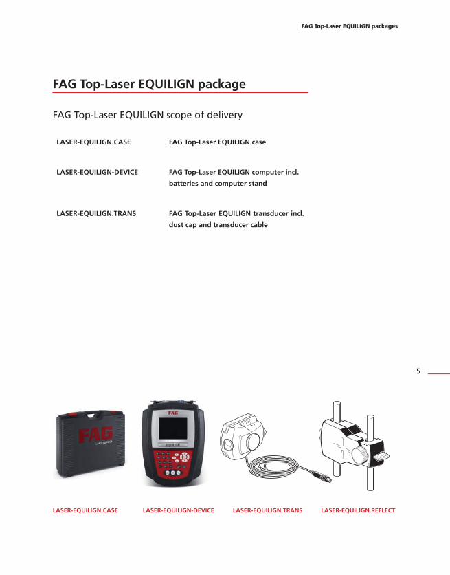
FAG Top-Laser EQUILIGN package
FAG Top-Laser EQUILIGN scope of delivery
LASER-EQUILIGN.CASE FAG Top-Laser EQUILIGN case
LASER-EQUILIGN-DEVICE FAG Top-Laser EQUILIGN computer incl.
batteries and computer stand
LASER-EQUILIGN.TRANS FAG Top-Laser EQUILIGN transducer incl.
dust cap and transducer cable
LASER-EQUILIGN.CASE LASER-EQUILIGN-DEVICE LASER-EQUILIGN.TRANS LASER-EQUILIGN.REFLECT
FAG Top-Laser EQUILIGN packages

FAG Top-Laser EQUILIGN operating handbook
6
LASER-EQUILIGN.REFLECT Reflector incl. dust cap
Chain-type bracket
Please note that there are two pieces in
the package
LASER-EQUILIGN.PC-CABLE PC cable for FAG Top-Laser EQUILIGN
LASER-EQUILIGN.USB-CABLE FAG Top-Laser EQUILIGN USB cable
FAG USB memory stick for firmware
upgrade
Lens cleaning cloth
LASER.TAPE Tape measure mm/inch
FAG Top-Laser EQUILIGN pocket guide
LASER-EQUILIGN.PC-CABLE
LASER-EQUILIGN.USB-CABLE
LASER.TAPE

7
Safety information
The FAG Top-Laser EQUILIGN system must only be used for the alignment and
calibration of machines in an industrial environment. Care must be taken to ensure
that the device is not subjected to mechanical knocks. FAG Top-Laser EQUILIGN must
only be operated by trained personnel. FAG Industrial Services GmbH accepts no
liability for damages caused by incorrect usage.
Symbols
The following symbols are used in this handbook to draw the reader's attention to
important parts of the text.
This symbol denotes general information and tips regarding the operation of
FAG Top-Laser EQUILIGN.
This symbol denotes information that must be followed in order to avoid damage
to equipment.
This symbol denotes information that must be followed in order to avoid
personal injury.
Numbers in red circles indicate the corresponding operating steps described in
this handbook and must be closely observed.
CE conformity and EMC
FAG Top-Laser EQUILIGN fulfils the EU Directives on electrical equipment (73/23/EEC)
and electromagnetic compatibility (EMC) (2004/108/EC).
FAG Top-Laser EQUILIGN has been tested in line with the following guidelines:
EN 50011 (VDE 0875-11), EN 61000 (VDE 0838) and EN 61326 (VDE 0843-20).
IP classification
FAG Top-Laser EQUILIGN is dust-tight and protected against water jets (IP 65). The
transducer and the reflector are protected against dust and temporary immersion in
water (IP 67).
Safety information
This symbol denotes general information and tips regarding the operation of
FAG Top-Laser EQUILIGN.
This symbol denotes information that must be followed in order to avoid damage
to equipment.
This symbol denotes information that must be followed in order to avoid
personal injury.
Numbers in red circles indicate the corresponding operating steps described in
this handbook and must be closely observed. 1
HNote
sWarning
aCaution

FAG Top-Laser EQUILIGN operating handbook
8
Laser safety
The FAG Top-Laser EQUILIGN is classified under laser protection class 2. Lasers in
protection class 2 comply with the requirements outlined in FDA specification 21 CFR,
Ch. 1, parts 1040.10 and 1040.11 as well as the ANSI standard. They also comply with
the British standard BS 4803 (Part 1 to Part 3) and the European industrial standard
IEC 825. Lasers in protection class 2 operate at a typical wavelength of 675 nm
with a maximum pulse duration of 128 μs, maximum radiant power of 0.8 mW and
maximum radiant energy per pulse of 0.1 μJ. No maintenance is required to keep this
device in line with the specifications mentioned above.
Never look directly into the laser beam!
Do not place any lenses or optical glass in the beam path.
The red LED on the transducer illuminates whenever the laser beam is being
emitted.
Operating information
Temperature range
The permissible temperature range for EQUILIGN and its components is between
0°C and 50°C. Higher or lower temperatures can distort the measurement results or
damage the components.
Store the FAG Top-Laser EQUILIGN system at temperatures between -20°C and 60°C.
External influences
Nearby sources of intense heat or water vapour could deflect the laser beam and
affect the accuracy of measurements. In practice, however, this effect rarely occurs at
distances up to 1 m. If in doubt, the laser beam can be shielded from environmental
influences during adjustment and measurement.
As with all optical precision measurement equipment, sudden fluctuations in
temperature (e.g. direct sunlight) could cause FAG Top-Laser EQUILIGN to produce
false measurements.
Allow adequate time for the FAG Top-EQUILIGN components to reach the
ambient temperature before taking any measurements.
Never look directly into the laser beam!
Do not place any lenses or optical glass in the beam path.
The red LED on the transducer illuminates whenever the laser beam is being
emitted.
Allow adequate time for the FAG Top-EQUILIGN components to reach the
ambient temperature before taking any measurements.
sWarning
HNote

9
Incident light
Protect the lens from strong incident light, e.g. direct sunlight.
Resistance to water spray and dust
The FAG Top-Laser EQUILIGN computer (IP 65), the transducer (IP 67) and the
reflector (IP 67) are protected against environmental influences. The components are
protected against water spray on all sides but should not remain fully submerged in
water over long periods. As with all waterproof electrical devices, the resistance of the
FAG Top-Laser EQUILIGN computer and its components should be checked regularly.
This can be carried out during calibration of the system, which we recommend be
completed every two years.
Interfaces
FAG Top-Laser EQUILIGN is fitted with two interfaces: one for data transfer to a
PC/printer and one for data transfer to the transducer.
Information on data storage
As with all electronic memory chips, data may be lost or modified under certain
circumstances. It is therefore advisable to keep a back-up copy and printed
records of particularly important data.
FAG Industrial Services GmbH accepts no liability for data lost as a result of
improper use, incorrect repairs, incorrect battery replacement or any other
operating errors.
FAG Industrial Services GmbH accepts no direct or indirect liability for financial
losses or claims from third parties resulting from lost or modified data.
Safety information
HNote
Information on data storage
As with all electronic memory chips, data may be lost or modified under certain
circumstances. It is therefore advisable to keep a back-up copy and printed
records of particularly important data.
FAG Industrial Services GmbH accepts no liability for data lost as a result of
improper use, incorrect repairs, incorrect battery replacement or any other
operating errors.
FAG Industrial Services GmbH accepts no direct or indirect liability for financial
losses or claims from third parties resulting from lost or modified data.
FAG Top-Laser EQUILIGN operating handbook
10
This page intentionally left blank.
FAG Top-Laser EQUILIGN overview
11
FAG Top-Laser EQUILIGN overview
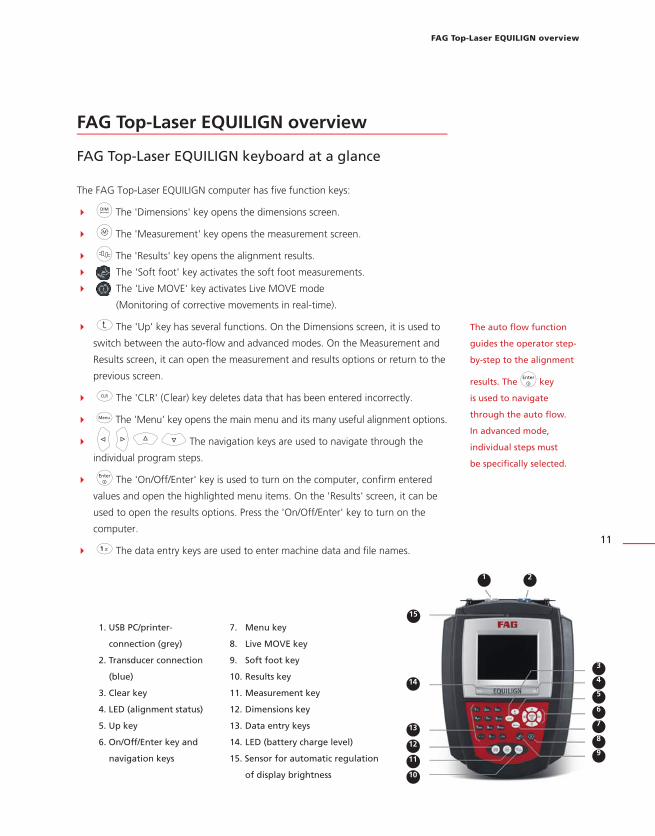
FAG Top-Laser EQUILIGN keyboard at a glance
The FAG Top-Laser EQUILIGN computer has five function keys:
d The 'Dimensions' key opens the dimensions screen.
m The 'Measurement' key opens the measurement screen.
k The 'Results' key opens the alignment results.
The 'Soft foot' key activates the soft foot measurements.
The 'Live MOVE' key activates Live MOVE mode
(Monitoring of corrective movements in real-time).
ß The 'Up' key has several functions. On the Dimensions screen, it is used to
switch between the auto-flow and advanced modes. On the Measurement and
Results screen, it can open the measurement and results options or return to the
previous screen.
c The 'CLR' (Clear) key deletes data that has been entered incorrectly.
q The 'Menu' key opens the main menu and its many useful alignment options.
h i f g The navigation keys are used to navigate through the
individual program steps.
e The 'On/Off/Enter' key is used to turn on the computer, confirm entered
values and open the highlighted menu items. On the 'Results' screen, it can be
used to open the results options. Press the 'On/Off/Enter' key to turn on the
computer.
1 The data entry keys are used to enter machine data and file names.
1. USB PC/printer-
connection (grey)
2. Transducer connection
(blue)
3. Clear key
4. LED (alignment status)
5. Up key
6. On/Off/Enter key and
navigation keys
1 2
4
5
6
7
8
9
13
12
10
11
3
14
7. Menu key
8. Live MOVE key
9. Soft foot key
10. Results key
11. Measurement key
12. Dimensions key
13. Data entry keys
14. LED (battery charge level)
15. Sensor for automatic regulation
of display brightness
The auto fl ow function
guides the operator step-
by-step to the alignment
results. The e key
is used to navigate
through the auto fl ow.
In advanced mode,
individual steps must
be specifi cally selected.
15
FAG Top-Laser EQUILIGN user manual
12
Power supply
FAG Top-Laser EQUILIGN is powered by five standard 'AA' batteries. These batteries
also serve as the power supply for the transducer and allow operation of up to nine
hours (33% active measurement, 33% stand-by, 33% 'sleep' mode).
Replacing disposable batteries
Batteries should be removed as soon as they become depleted or if the system has
not been used for an extended period. Any type of high-quality 'AA' size batteries
can be used in the FAG Top-Laser EQUILIGN standard computer, including alkaline-
manganese batteries or high-capacity batteries, e.g. Duracell PLUS MN 1500. It is
recommended to replace all five batteries together. Note the battery polarity when
inserting the batteries in the battery compartment.
To replace the batteries, turn over the computer while taking care not to damage the
display or the keys. The locking screw for the battery housing can be loosened with a
quarter-turn of a 7-mm screwdriver. When the screw comes loose, lift off the cover of
the battery housing and remove the batteries.
Dispose of used batteries in accordance with applicable regulations! mDispose of used batteries in accordance with applicable regulations!
FAG Top-Laser EQUILIGN overview
13
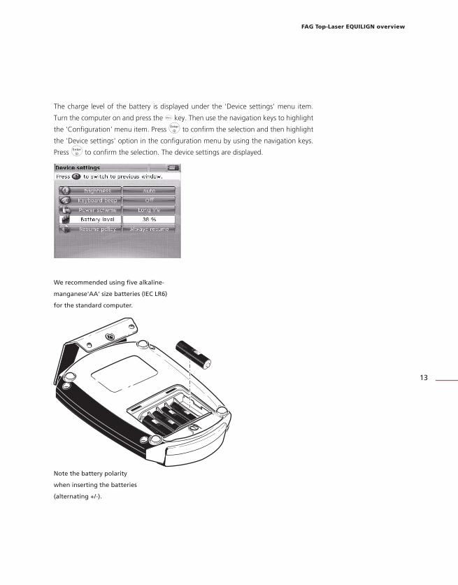
The charge level of the battery is displayed under the 'Device settings' menu item.
Turn the computer on and press the q key. Then use the navigation keys to highlight
the 'Configuration' menu item. Press e to confirm the selection and then highlight
the 'Device settings' option in the configuration menu by using the navigation keys.
Press e to confirm the selection. The device settings are displayed.
We recommended using fi ve alkaline-
manganese 'AA' size batteries (IEC LR6)
for the standard computer.
Note the battery polarity
when inserting the batteries
(alternating +/-).
Baby LR 14 C AM2
No 4014 1,5 V
Nicht ins Feuer werfen!
Nicht wiederaufladbar.
May explode in fire! Not rechargeable.
Ne pas jeter au feu! non rechargeable.
Baby LR 14 C AM2
No 4014 1,5 V
Baby LR 14 C AM2
No 4014 1,5 V
Nicht ins Feuer werfen!
Nicht wiederaufladbar.
May explode in fire! Not rechargeable.
Ne pas jeter au feu! non rechargeable.
Baby LR 14 C AM2
No 4014 1,5 V
Baby LR 14 C AM2
No 4014 1,5 V
Nicht ins Feuer werfen!
Nicht wiederaufladbar.
May explode in fire! Not rechargeable.
Ne pas jeter au feu! non rechargeable.

FAG Top-Laser EQUILIGN user manual
14
Transducer
The transducer contains a laser diode that emits a beam of red light (wavelength
675 nm). The beam becomes visible when it hits a surface. It is emitted with a diameter
of approx. 5 mm. The same housing also contains a position detector that measures
the exact position of the laser beam as the shafts are rotated. This component is a
biaxial, analogue, photoelectric semiconductor position detector with a resolution of
1 μm. The transducer also contains an electronic inclinometer with a resolution better
than 1° for measuring the shaft rotation angle.
There are two indicator LEDs on the front of the transducer: a green LED for indicating
beam adjustment and a red LED to indicate when the laser is switched on. The
transducer is powered by the FAG Top-Laser EQUILIGN computer via a cable that is
also used to transfer measurement data.
The transducer is protected against environmental influences (IP 67). The internal
optics and electronics are sealed to prevent any possible contamination. However,
the transducer lens must be kept clean. Use the lens cleaning cloth provided or a fine
dusting brush such as those normally used to clean other optical devices. Keep the
dust cap on when the transducer is not in use.
Avoid polishing the lens too vigorously to prevent irreparable damage to
the anti-reflective coating.
Do not remove the six smaller housing screws sealing the housing under
any circumstances. This can lead to misalignment of the laser. Warranty
claims are void if the housing is opened!
The calibration of the transducer should be checked every two years —
as indicated by the coloured label on the transducer. Please contact our
support centre for calibration checking.
Never look directly into the laser beam!
aCaution
HNote
sWarning

FAG Top-Laser EQUILIGN overview
15
The reflector is mounted on the shaft or the coupling half of the machine that is to
be moved. It reflects the laser beam back into the position detector as the shafts are
rotated. The locking lever is moved to the horizontal position to hold the reflector
in place on the supporting rails. The reflector is adjusted by changing its vertical
position and horizontal angle (adjustment screw, adjustment knob) so that the beam
is reflected directly back into the transducer.
The reflector must be kept clean. Use the lens cleaning cloth provided or a fine dusting
brush such as those normally used to clean other optical devices.
Avoid rubbing the reflective surface too vigorously as this can lead to irreparable
damage to the anti-reflective coating. Keep the dust cap on when the reflector
is not in use.
Avoid rubbing the reflective surface too vigorously as this can lead to irreparable
damage to the anti-reflective coating. Keep the dust cap on when the reflector
is not in use.
aCaution
90° roof
prism
Vertical position
adjustment screw
Measure mark = centre
of supporting rails
Adjustment knob for horizontal
angular adjustment
Locking lever
IP 67 housing
Power/data cable
Scratch-resistant lens
Housing mark =
centre of supporting rails
Green LED: Indicates the
laser adjustment
Locking screw
Red LED: Illuminates when transducer
and laser are switched on
Refl ector

FAG Top-Laser EQUILIGN user manual
16
Compact chain-type bracket
Compact and lightweight, the chain-type bracket provides sturdy support for the measurement components. This
easy-to-mount holding device is suitable for shaft diameters ranging between 15 mm and 500 mm. The bracket
covers the full range of diameters — limitations are due to the chain length (chains of varying lengths are available).
Mounting instructions can be found in the 'Horizontal machine alignment' chapter on Page 37. Other chain and
rail types are available. Contact your local representative for details on additional accessories.
Optional compact magnetic
bracket
Compact chain-type
bracket

Configuration
17
Configuration and data management
Confi guration
The 'Configuration' menu item is used to configure FAG Top-Laser EQUILIGN settings,
regional settings, default settings and printer settings. It can also be used to open
detailed information about the device.
The Configuration menu can be opened at any time and from any screen. With the
FAG Top-Laser EQUILIGN computer switched on, press the q key to open the
Configuration menu. The following screen appears. Use the navigation keys to
highlight the 'Config' icon.
When 'Config' is highlighted, press e to open the Configuration menu.
Use the navigation keys
to highlight the required
configuration menu items.

FAG Top-Laser EQUILIGN operating handbook
18
Device settings
To open the 'Device settings' screen, highlight the 'Device settings' menu item using
the navigation keys and then press e to confirm the selection. The possible settings
are displayed. These are brightness, keyboard beep, power scheme, battery level and
resume policy. Highlight the desired menu item using the f/g keys.
There are two modes to regulate display brightness in the FAG Top-Laser EQUILIGN
computer. The auto mode uses a light sensor to automatically adjust the display
brightness to the ambient lighting conditions. To adjust the display brightness
manually, switch to manual mode using the e/h/i keys. Increase the display
brightness using the i key or decrease it using the h key.
Press e to turn the keyboard beep on or off. If the keyboard beep is activated, each
key will make a beeping sound when pressed.
FAG Top-Laser EQUILIGN
offers two display
brightness modes:
automatic mode and
manual mode. Automatic
mode automatically adjusts
the brightness to the
ambient lighting conditions.

Configuration
19
The ' Power scheme' option is used to select a setting that manages the power usage
of the FAG Top-Laser EQUILIGN. The three options are: 'Standard' (the display dims
after ten minutes and turns off after 60 minutes), 'Full power' (does not dim or turn
off automatically) and 'Long life' (dims after three minutes, turns off after eight
minutes). Select the desired setting using the f/g keys and press e to
confirm the selection.
The current battery capacity is displayed next to the ' battery level' bar. This value
corresponds with the charge level of the battery icon in the top right-hand corner of
the screen.
The charge level of the
battery is displayed in the
top right-hand corner of
every screen.

FAG Top-Laser EQUILIGN operating handbook
20
'Resume policy' allows the user to specify the measurement file that opens when the
FAG Top-Laser EQUILIGN computer is switched on. It may be set to automatically
open the last used measurement file ('automatic') or open a new measurement file
('manual'). Press e to switch between these two options.
Regional settings
This option is used to set the units of measurement, preferred language and the date
and time. Open the configuration menu screen. Use the navigation keys to highlight
the 'Regional settings' menu item and then press e to confirm the selection.
Highlight the ' Units' menu item using the f/g keys and press e to confirm
the selection. The measurement units available for selection are American, English
and metric units (SI units). Select the desired system of units using the f/g
keys. Press e to confirm the selection.
The h/i keys can also
be used to switch between
the two 'Resume policy'
options.

Configuration
21
Highlight the ' Language' menu item using the f/g keys and press e to
confirm the selection. Select the required language from the list using the f/g
keys. Press e to confirm the selection.
Before the chosen language is set, a query appears asking whether the system
of units and the date and time format should also be changed to match the new
language selection. Select the action required using the f/g keys and
then press e.
Highlight the ' Time zone' menu item using the f/g keys and press e to
confirm the selection. Select the required time zone using the f/g keys and
confirm your selection by pressing e.
Set the current date and time by highlighting the relevant option using the f/g
keys. Press e to confirm the selection.
Before the chosen language is set, a query appears asking whether the system
of units and the date and time format should also be changed to match the new
language selection. Select the action required using the f/g keys and
then press e.
HNote
When a time zone is
opened, a box appears
displaying the major world
cities in that time zone.
Note: Changing the time
zone automatically adjusts
the time.
Note: The date format
displayed here can be set
via the 'Date/time format'
option.

FAG Top-Laser EQUILIGN operating handbook
22
Highlight the date (day, month or year, depending on the display format) using the
h/i keys. Set the highlighted date component using the f/g keys. Use the
f key to increase the values and the g key to decrease the values.
Alternatively, the date can also be set using the data entry keys. Highlight the required
data component and directly enter the new value using the data entry keys. The
editing box appears as soon as the first key is pressed.
Enter a value and press e or ß to confirm the entry.
Switch between the hours and minutes using the h/i keys. Set the highlighted
time component using the f/g keys. Use the f key to increase the values
and the g key to decrease the values. Alternatively, the time can also be set using
the data entry keys. Highlight the required time component and directly enter the
new value using the data entry keys. The editing box appears as soon as the first key
is pressed. Enter a value and press e or ß to confirm the entry.
Note: The time format
displayed here can be set
via the 'Date/time format'
option.
Configuration
23
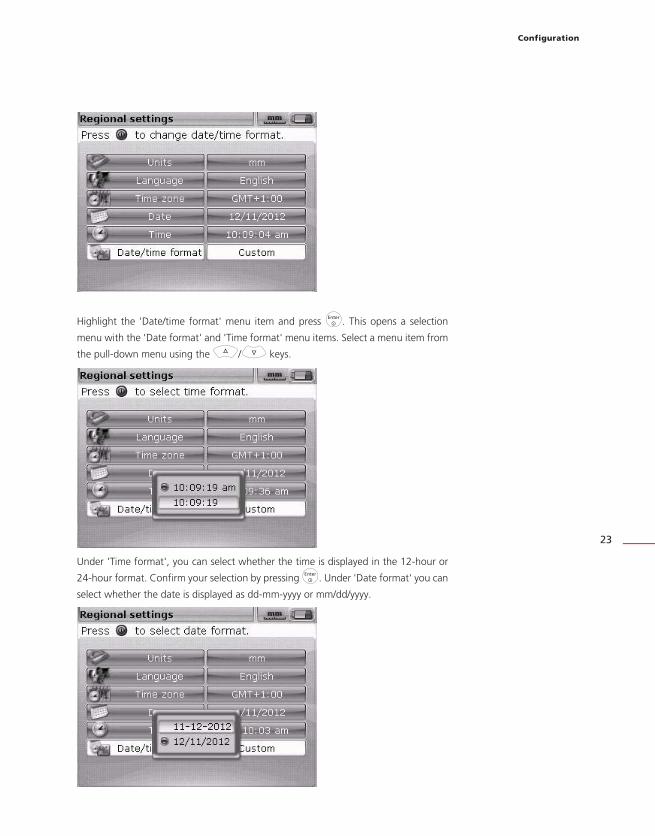
Highlight the 'Date/time format' menu item and press e. This opens a selection
menu with the 'Date format' and 'Time format' menu items. Select a menu item from
the pull-down menu using the f/g keys.
Under 'Time format', you can select whether the time is displayed in the 12-hour or
24-hour format. Confirm your selection by pressing e. Under 'Date format' you can
select whether the date is displayed as dd-mm-yyyy or mm/dd/yyyy.

FAG Top-Laser EQUILIGN operating handbook
24
Default settings
To open the ' Default settings' screen, use the navigation keys to highlight the 'Default
settings' option in the configuration menu and then press e to confirm the selection.
This screen is used to set specific default settings. Any changes made to the default
settings come into effect when the computer is restarted or if a new file is created.
Default RPM — used to set the required default RPM. Highlight the 'Default
RPM' menu item and enter the required value using the data entry keys. Press
e or ß to confirm the entry.
Ref. diameter — used to set the required reference diameter. Highlight the 'Ref.
diameter' menu item and enter the required diameter using the data entry keys.
Press e or ß to confirm the entry. When opened, every new alignment file
will contain the predetermined RPM value and reference diameter.
Tolerance table — the available options are 'On' or 'Off'. The RPM determines
the correct tolerance value. Tolerance values based on these RPMs can be
obtained from the FAG Industrial Services GmbH tolerance table.
Navigate through the
parameters using f
or g.
Configuration
25
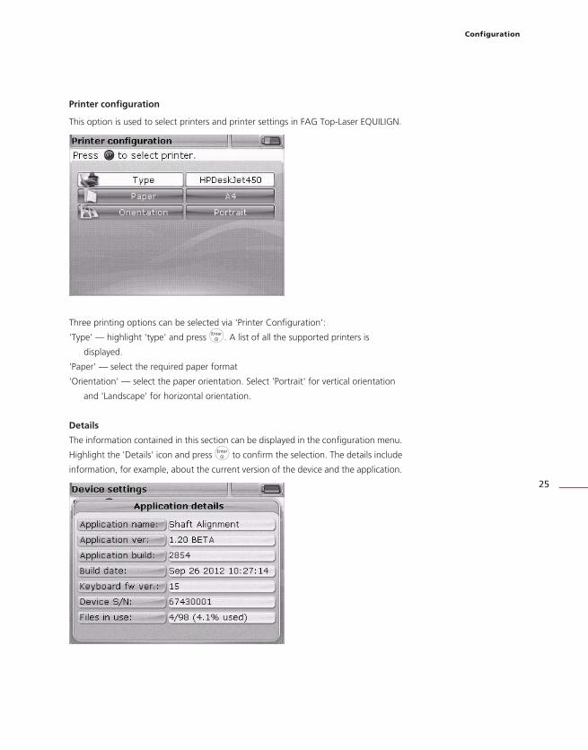
Printer configuration
This option is used to select printers and printer settings in FAG Top-Laser EQUILIGN.
Three printing options can be selected via 'Printer Configuration':
'Type' — highlight 'type' and press e. A list of all the supported printers is
displayed.
'Paper' — select the required paper format
'Orientation' — select the paper orientation. Select 'Portrait' for vertical orientation
and 'Landscape' for horizontal orientation.
Details
The information contained in this section can be displayed in the configuration menu.
Highlight the 'Details' icon and press e to confirm the selection. The details include
information, for example, about the current version of the device and the application.

FAG Top-Laser EQUILIGN operating handbook
26
Data managementFAG Top-Laser EQUILIGN features an effective system for managing data and files.
Press the q key to open the data management options and highlight the 'File' icon
using the navigation keys.
Press e to confirm the selection. The file management menu appears.
Highlight one of the four data management options using the h/i keys. The
available options are 'Files list', ' Save file', 'Resume' (or ' New file') and 'Print report'.
Note: The 'New file' and 'Resume' menu items are dependent on the selected
resume policy, which can be selected in the configuration menu under 'Device
settings'. 'Resume' only appears when the resume policy is set to 'Manual'.
Navigate through the four
items in the file menu using
h or i.
Note: Highlighted menu
items are identified by an
orange rectangle.
Note: The 'New file' and 'Resume' menu items are dependent on the selected
resume policy, which can be selected in the configuration menu under 'Device
settings'. 'Resume' only appears when the resume policy is set to 'Manual'. HNote

Configuration
27
' Files list' — this option is used to load any stored file. Highlight 'Files list' using the
h/i keys and press e to confirm the selection. A list of all the saved files is
displayed.
Highlight the file you want to open using the f/g keys and then press e.
To delete an existing file, highlight the file using the f/g keys and press
the c key. On the next screen, highlight 'Yes' using the f/g keys.
Press e to confirm deletion. To rename an existing file, highlight the file using
the f/g keys, enter the new file name using the data entry keys and
press e to confirm the change.
' Save file' — this option is used to save the current file. If the file is new and currently
unnamed, use the data entry keys to enter the new data name in the editing box.
The files are arranged
according to date and
time of creation. This order
cannot be changed.
HNote
To delete an existing file, highlight the file using the f/g keys and press
the c key. On the next screen, highlight 'Yes' using the f/g keys.
Press e to confirm deletion. To rename an existing file, highlight the file using
the f/g keys, enter the new file name using the data entry keys and
press e to confirm the change.
If the file name already
exists, the editing box
appears with the existing
file name highlighted.
Press e to confirm the
selection.
FAG Top-Laser EQUILIGN operating handbook
28
Press e to confirm the file name.
You can store up to 100 measurement files.
'New file' — this menu item appears in the file menu if the resume policy in device
settings is set to 'Automatic'.
' Resume' — this menu item appears in the data menu instead of 'New file' if
the resume policy in device settings is set to 'Manual'. This menu item is used to
automatically open the last file that was used before the computer was turned off.
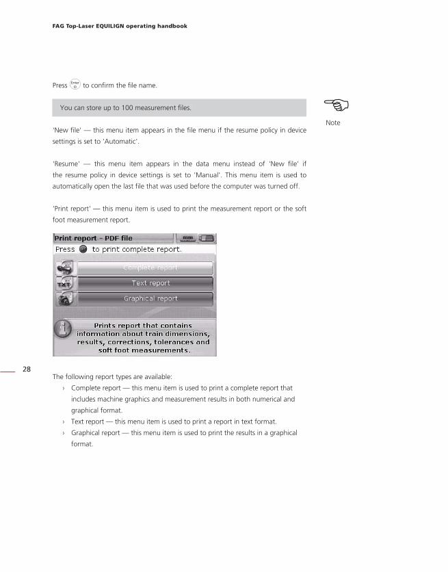
'Print report' — this menu item is used to print the measurement report or the soft
foot measurement report.
The following report types are available:
› Complete report — this menu item is used to print a complete report that
includes machine graphics and measurement results in both numerical and
graphical format.
› Text report — this menu item is used to print a report in text format.
› Graphical report — this menu item is used to print the results in a graphical
format.
HNote
You can store up to 100 measurement files.
Getting started
29
Getting started
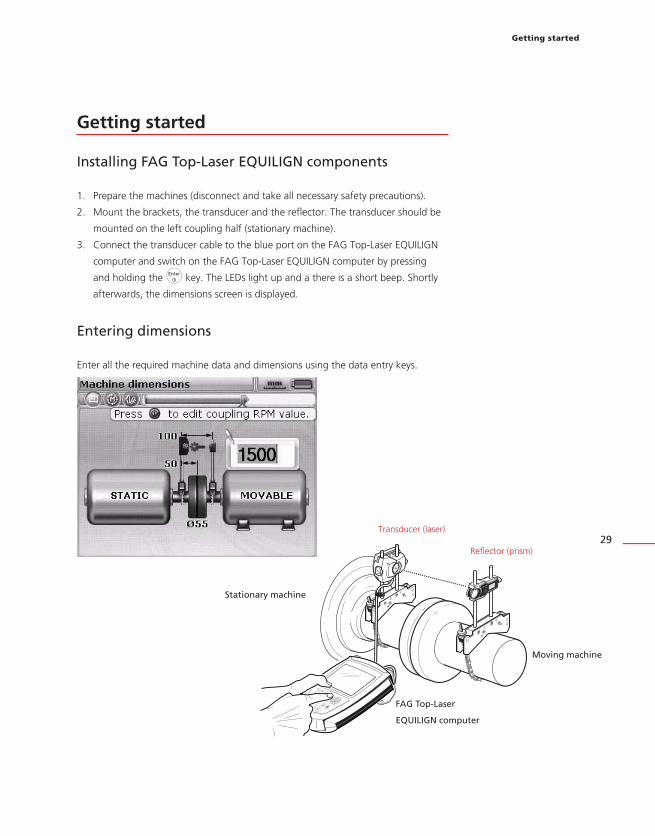
Installing FAG Top-Laser EQUILIGN components
1. Prepare the machines (disconnect and take all necessary safety precautions).
2. Mount the brackets, the transducer and the reflector. The transducer should be
mounted on the left coupling half (stationary machine).
3. Connect the transducer cable to the blue port on the FAG Top-Laser EQUILIGN
computer and switch on the FAG Top-Laser EQUILIGN computer by pressing
and holding the e key. The LEDs light up and a there is a short beep. Shortly
afterwards, the dimensions screen is displayed.
Entering dimensions
Enter all the required machine data and dimensions using the data entry keys.
Stationary machine
Moving machine
Transducer (laser)
Reflector (prism)
FAG Top-Laser
EQUILIGN computer
FAG Top-Laser EQUILIGN operating handbook
30
An editing box appears with information about the machine data that must be
entered or edited. Enter the machine data using the data entry keys and confirm the
entry by pressing the e key. The highlighted box moves automatically to the next
empty field and a corresponding message appears. Repeat this process until all the
required dimensions have been entered. The following dimensions must be entered:
1. Distance from transducer (sensor/laser) to reflector (prism)
2. Distance from transducer (sensor/laser) to centre of coupling
3. Coupling diameter (default is 100 mm. This default value can be changed;
see the 'Default settings' section on Page 24.)
4. RPM (see the 'Default settings' section on Page 24)
5. Distance from centre of coupling to front feet (machine on the right)
6. Distance from front feet to back feet (machine on the right)
When all of the required dimensions have been entered, the measurement screen
appears automatically.
The dimensions screen can be reopened at any time using the d key.
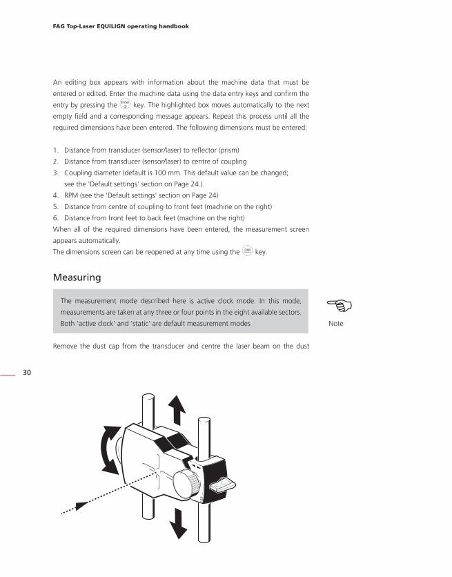
Measuring
The measurement mode described here is active clock mode. In this mode,
measurements are taken at any three or four points in the eight available sectors.
Both 'active clock' and 'static' are default measurement modes.
Remove the dust cap from the transducer and centre the laser beam on the dust
HNote
The measurement mode described here is active clock mode. In this mode,
measurements are taken at any three or four points in the eight available sectors.
Both 'active clock' and 'static' are default measurement modes.

Getting started
31
cap of the reflector. If the dust cap is on, the message 'Laser off' will appear on the
screen and the indicator LED for the alignment status on the FAG Top-Laser EQUILIGN
computer will light up in red.
Do not look into the laser beam! Risk of injury!
If necessary, adjust the chain-type bracket so that the laser beam is centred
horizontally on the reflector, then secure the chain-type bracket. Slide the reflector on
the supporting rails to centre the laser beam vertically on the reflector dust cap. When
the laser beam is centred, remove the dust cap from the reflector.
In order to position the laser beam in the centre or as close to the centre as possible,
use the adjustment screw on the side of the reflector to make vertical adjustments
and the yellow adjustment knob to make horizontal adjustments.
When making the adjustments mentioned above, take note of the LEDs on the
FAG Top-Laser EQUILIGN computer and the laser dot on the display screen. The
LED lights up in green when the laser position is suitable and measuring can
commence. The LED lights up in blue when the laser beam is centred exactly in
the target box.
Further information about adjusting the laser beam can be found from Page 45.
Once the laser beam has been centred exactly, rotate the shafts to the first
measurement position. Measurements can only be taken if the sector in which the
shaft rotates is highlighted. Press e to take the first measurement. The sector is now
marked in black, indicating that a measurement has already been taken in that sector.
Do not look into the laser beam! Risk of injury! sWarning
When making the adjustments mentioned above, take note of the LEDs on the
FAG Top-Laser EQUILIGN computer and the laser dot on the display screen. The
LED lights up in green when the laser position is suitable and measuring can
commence. The LED lights up in blue when the laser beam is centred exactly in
the target box.
HNote

FAG Top-Laser EQUILIGN operating handbook
32
Rotate the shafts to the next measurement position and take a measurement point.
Three or four measurement values (depending on the default settings; see Page
24) from the eight possible positions are required for an analysis of the results.
Measurements can be carried out in any order. The results screen opens automatically
after all the required measurements points have been taken.
Results
The alignment results, with both coupling and foot values, are displayed automatically.
Coupling results are given in the form of gap and offset values. If the stationary
machine is to the left of the viewer, the gap is positive when it opens at the top or
away from the viewer. The offset is positive if the moving machine (on the right) is
higher or further away from the viewer.
The coupling values (1) and
foot values (2) are displayed
in both horizontal and
vertical directions.
The foot results indicate the
foot positions relative to the
centre axis of the stationary
machine.
1
2
2
1

Getting started
33
Positive values in the foot results mean that the machine on the right is higher or
further away from the viewer. Negative values mean that the machine on the right
is lower or closer to the viewer. The alignment status is displayed using the tolerance
icon.
'Thumbs up' icon (the alignment status LED lights up blue) —
measured values within good tolerances ILIGN
'Thumbs down' icon (the alignment status LED lights up red)
— measured values outside tolerances ILIGN

FAG Top-Laser EQUILIGN operating handbook
34
This page intentionally left blank.

Horizontal machine alignment
35
Horizontal machine alignment
1. Preparing the alignment process
Before you use the FAG Top-Laser EQUILIGN system, prepare the machine as follows:
Before starting any work, disconnect the machine so that it cannot be activated
accidentally.
a. Stable and flat base
A solid and stable base is required to obtain correct, lasting alignment of the machine.
b. Machine mobility
If the machine to be moved is standing directly on the base, it cannot be lowered for
alignment correction. It is therefore advisable to insert 2 mm shims under the feet of
the machine before commencing alignment. Adjustable screws or hydraulic aids are
recommended for any movement.
c. Rigid couplings
Rigid couplings must be loosened before alignment so that the alignment conditions
are not negatively affected.
d. Torsion play/axial play
Torsion play on the coupling should be avoided. Axial shaft play up to 3 mm has no
significant effect on measurement results (though it may affect machine operation).
e. Soft foot
When the fixing screws on a machine are loosened, the tension causes the machine
foot to lift up and change the position of the shaft. Precise machine movement during
alignment is therefore not possible.
f. Coupling requirements/tolerances
The machine default values can be obtained from the machine specifications.
Before starting any work, disconnect the machine so that it cannot be activated
accidentally. sWarning

FAG Top-Laser EQUILIGN operating handbook
36
g. Measurement distance
As the FAG Top-Laser EQUILIGN system does not require mechanical connections
across the coupling (e.g. dial indicator brackets) during measurement, measurements
can be carried out easily over large distances between transducer and reflector.
Shafts and couplings may sag over large distances and it may be necessary to take
this into account when aligning the machine. In this case, refer to the manufacturer's
specifications.
2. Checking for soft foot
See the 'Soft foot' chapter on page 71.
3. Mounting the chain-type brackets
Mount a bracket on either side of the coupling and ensure that both are at the same
angle.
When mounting the brackets please note the following information in order to obtain
the highest possible measurement accuracy and to avoid damage to the equipment:
The brackets for the transducer and the reflector must be mounted
securely.
Do not use self-constructed brackets. Never modify the original brackets
supplied by FAG Industrial Services GmbH. Do not use support rails longer
than those recommended for the respective brackets. FAG Industrial
Services GmbH supplies support rails and chains in varying lengths.
Mounting procedure
To mount the brackets, refer to the diagrams provided and follow the instructions:
The brackets for the transducer and the reflector must be mounted
securely.
Do not use self-constructed brackets. Never modify the original brackets
supplied by FAG Industrial Services GmbH. Do not use support rails longer
than those recommended for the respective brackets. FAG Industrial
Services GmbH supplies support rails and chains in varying lengths. sWarning
aCaution
Horizontal machine alignment
37
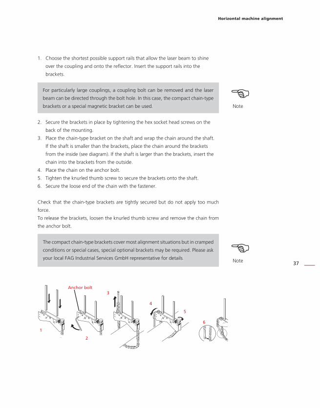
1. Choose the shortest possible support rails that allow the laser beam to shine
over the coupling and onto the reflector. Insert the support rails into the
brackets.
For particularly large couplings, a coupling bolt can be removed and the laser
beam can be directed through the bolt hole. In this case, the compact chain-type
brackets or a special magnetic bracket can be used.
2. Secure the brackets in place by tightening the hex socket head screws on the
back of the mounting.
3. Place the chain-type bracket on the shaft and wrap the chain around the shaft.
If the shaft is smaller than the brackets, place the chain around the brackets
from the inside (see diagram). If the shaft is larger than the brackets, insert the
chain into the brackets from the outside.
4. Place the chain on the anchor bolt.
5. Tighten the knurled thumb screw to secure the brackets onto the shaft.
6. Secure the loose end of the chain with the fastener.
Check that the chain-type brackets are tightly secured but do not apply too much
force.
To release the brackets, loosen the knurled thumb screw and remove the chain from
the anchor bolt.
The compact chain-type brackets cover most alignment situations but in cramped
conditions or special cases, special optional brackets may be required. Please ask
your local FAG Industrial Services GmbH representative for details.
HNote
The compact chain-type brackets cover most alignment situations but in cramped
conditions or special cases, special optional brackets may be required. Please ask
your local FAG Industrial Services GmbH representative for details. HNote
Anchor bolt
1
2
3
4
5
6
For particularly large couplings, a coupling bolt can be removed and the laser
beam can be directed through the bolt hole. In this case, the compact chain-type
brackets or a special magnetic bracket can be used.
FAG Top-Laser EQUILIGN operating handbook
38
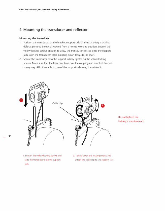
4. Mounting the transducer and refl ector
Mounting the transducer
1. Position the transducer on the bracket support rails on the stationary machine
(left) as pictured below, as viewed from a normal working position. Loosen the
yellow locking screws enough to allow the transducer to slide onto the support
rails, with the transducer cable pointing down towards the shaft.
2. Secure the transducer onto the support rails by tightening the yellow locking
screws. Make sure that the laser can shine over the coupling and is not obstructed
in any way. Affix the cable to one of the support rails using the cable clip.
1. Loosen the yellow locking screws and
slide the transducer onto the support
rails.
2. Tightly fasten the locking screws and
attach the cable clip to the support rails.
Cable clip
1
2
Do not tighten the
locking screws too much.

Horizontal machine alignment
39
Mounting the reflector
a. Position the reflector on the bracket support rails on the machine on the right
(moveable).
The yellow adjustment knob on the front of the reflector is used to set the horizontal
angle of the reflected laser beam. A rough estimation of this angle must be set before
mounting the reflector to allow for rapid and precise adjustment on the detector
surface. Check the position of the yellow adjustment knob. The back of the yellow
adjustment knob must be flush with the arrow marker on the housing.
b. Put the mounted locking lever on the side of the reflector in the vertical, open
position. Slide the reflector onto the bracket support rails that are mounted
on the moveable machine, as shown on the right. Secure the reflector to the
support rails by returning the lever to the horizontal position.
The transducer and reflector should be at the same height and as low as possible,
but must still allow the laser beam to shine over the coupling. Make sure that the
transducer and reflector are in line with each other.
If necessary, loosen the brackets and rotate into the correct position. Retighten the
brackets before continuing.
Attach the reflector (locking lever in horizontal position).
The adjustment knob allows fine adjustments to be made.
Move the adjustment knob to sit
flush with the arrow marker.
Too high! Too low!
Arrow marker
Locking lever open (vertical position).
Locking lever
a
b

FAG Top-Laser EQUILIGN operating handbook
40
Disconnecting the transducer
Carefully remove the plug from the computer by grasping the ribbed collar as far
forward as possible.
6. Switching on FAG Top-Laser EQUILIGN and starting
applications
Press e and hold down the key for a few seconds. The display LED for the alignment
status illuminates and a beep sounds. The start screen appears shortly afterwards,
followed by the dimensions screen for shaft alignment.
5. Connecting the transducer
Insert the plug of the transducer cable into the blue port on the top of the computer
housing.
Turn the plug so that the arrow matches up with the white arrow on the blue
port to ensure the plug is orientated correctly; otherwise, the contact pins inside
the plug may become damaged.
Note the white arrow on
the blue port
Turn the plug so that the arrow matches up with the white arrow on the blue
port to ensure the plug is orientated correctly; otherwise, the contact pins inside
the plug may become damaged.aCaution

Horizontal machine alignment
41
7.1 Entering dimensions
Machine data and measurements are entered using the grey data entry keys.
An editing box appears with information about the measurement that must be
entered or edited. Any missing measurements that are required can be entered
directly using the data entry keys.
Confirm the entered value by pressing e. The highlighted box moves automatically
to the next missing measurement.
In advanced entry mode, the dimensions can also be accessed using the
navigation keys. Entered values can then be confirmed by pressing e or ß.
Alternatively, auto fl ow
mode can be overridden
using the ß key. This
allows activation of
advanced entry mode,
which can be used to
access editing boxes and
machine elements using
the navigation keys.
In advanced entry mode, the dimensions can also be accessed using the
navigation keys. Entered values can then be confirmed by pressing e or ß. HNote

FAG Top-Laser EQUILIGN operating handbook
42
The dimensions to be entered vary according to the machine and the coupling type.
For standard horizontal alignment, enter the following dimensions:
7.1.1 Distance from transducer to reflector
This is the distance between the markings on top of the transducer and the reflector
(refer to the diagrams below).
7.1.2 Distance from transducer to centre of coupling
This is the distance between the marking on top of the transducer and the centre of
the coupling.
This distance is calculated automatically from the entered distance from the transducer
to the reflector. The value can be entered directly in the editing box and confirmed
by pressing e.
In advanced mode, the distance is calculated and highlighted automatically. If
this value needs to be edited, enter the new value directly using the data entry
keys. The editing box appears as soon as the first key is pressed. Press either e
or ß to confirm the entry.
1
2
HNote
In advanced mode, the distance is calculated and highlighted automatically. If
this value needs to be edited, enter the new value directly using the data entry
keys. The editing box appears as soon as the first key is pressed. Press either eor ß to confirm the entry.
Marking for distance measurement =
centre of the support rails

Horizontal machine alignment
43
In advanced mode, the navigation keys can be used to move the marking
through the editing boxes and machines.
7.1.3 Coupling diameter
Measure the circumference of the coupling and divide this value by 3.142 (pi).
The default value is 100 mm. If this value needs to be edited, highlight the value using
the navigation keys. Press e to open the editing box. Change the value using the
data entry keys.
Confirm the entered value by pressing e or ß. The highlighted box moves
automatically to the next missing measurement.
7.1.4 RPM
The default value is 1500. If this value needs to be edited, highlight the value using
the navigation keys. Press e to open the editing box. Change the value using the
data entry keys.
7.1.5 Distance from centre of coupling to front feet, machine on the right
This is the distance from the centre of the coupling to the feet of the machine on the
right that are nearest to the coupling.
7.1.6 Distance from front feet to rear feet, machine on the right
This is the distance between the front feet and the rear feet of the machine on the
right.
In advanced mode, the navigation keys can be used to move the marking
through the editing boxes and machines. HNote
3
4
5
12
3
4
5
FAG Top-Laser EQUILIGN operating handbook
44
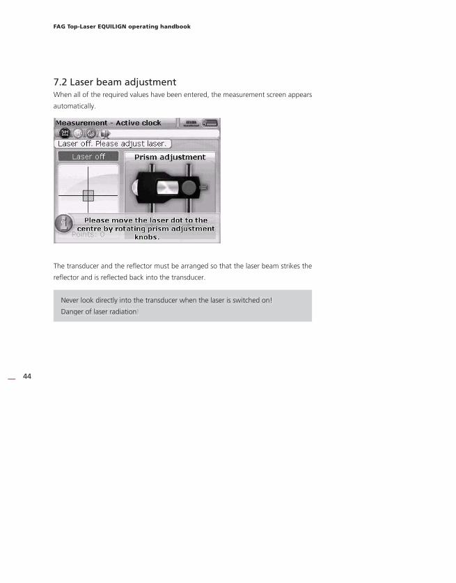
7.2 Laser beam adjustmentWhen all of the required values have been entered, the measurement screen appears
automatically.
The transducer and the reflector must be arranged so that the laser beam strikes the
reflector and is reflected back into the transducer.
Never look directly into the transducer when the laser is switched on!
Danger of laser radiation!
Never look directly into the transducer when the laser is switched on!
Danger of laser radiation!

Horizontal machine alignment
45
7.2.1 Remove the transducer dust cap
The laser beam is now on! Leave the other dust cap on the reflector so that the laser
beam is visible on it. If the laser does not strike the reflector, hold a white sheet of
paper in front of the reflector to locate the laser beam.
7.2.2 Centre the laser beam on the reflector dust cap
Leave the dust cap on the reflector and adjust the laser beam so that it strikes the
crosshairs on the dust cap:
› To set the laser vertically, slide the reflector and/or transducer up and down
the support posts. Use the adjustment screw on the side of the reflector
housing. Loosen the locking screws to move the transducer.
› To adjust the laser horizontally, loosen one of the chain-type brackets and
rotate it slightly. Retighten the chain-type bracket after adjustment.
7.2.3 Adjust the reflector until both of the LEDs on the transducer flash in
unison and the LED on the FAG Top-Laser EQUILIGN computer lights up blue
Red and green LEDs on the transducer indicate the laser beam alignment status.
An indicator LED on the FAG Top-Laser EQUILIGN computer can also be used
simultaneously to read this alignment status.
The reflector prism and transducer lens must be clean — use a lint-free cloth.
A lens cleaning cloth is supplied.
If the red LED on the transducer flashes quickly (every 0.3 seconds) and the FAG
Top-Laser EQUILIGN indicator LED on the computer lights up red, the laser beam is
failing to strike the position detector. The message 'Laser off' then appears on the
computer screen. Use the metal thumbwheel and yellow adjustment knob to adjust
the reflected laser beam, as described on the following page. If the laser beam strikes
the edge of the position detector, the computer LED lights up yellow and the red
transducer LED continues to flash red. The message 'Laser end' then appears on the
computer screen.
7.2.5 Centre the laser beam so that the indicator LED on the FAG Top-Laser
EQUILIGN computer light up blue.
Adjust the laser beam so that the laser dot strikes the display screen inside the green
box in the centre of the detector display.
HNote
› To set the laser vertically, slide the reflector and/or transducer up and down
the support posts. Use the adjustment screw on the side of the reflector
housing. Loosen the locking screws to move the transducer.
› To adjust the laser horizontally, loosen one of the chain-type brackets and
rotate it slightly. Retighten the chain-type bracket after adjustment.
HNote
The reflector prism and transducer lens must be clean — use a lint-free cloth.
A lens cleaning cloth is supplied.

FAG Top-Laser EQUILIGN operating handbook
46
x = set horizontally with the yellow adjustment knob
y = set vertically with the thumbwheel on the side
The LED on the FAG Top-Laser EQUILIGN computer lights up blue.
The RED LED on the
transducer flashes quickly,
the GREEN LED is off and
the indicator LED on the
FAG Top-Laser EQUILIGN
computer lights up RED.
Both transducer LEDs flash
alternately and the indicator
LED on the FAG Top-Laser
EQUILIGN computer lights
up YELLOW.
Vertical
adjustment
Horizontal adjustment

Horizontal machine alignment
47The co-ordinates do not have to be set exactly to (0.0) to obtain precise
measurements, but the maximum measurement range is available in all directions
if the laser beam is centred.
Do not touch components!
The adjusted components must not be touched during the measurement
process, as this could adjust them further, which would deliver incorrect results.
Both transducer LEDs
flash slowly in unison and
the indicator LED on the
FAG Top-Laser EQUILIGN
computer lights up GREEN.
The arrow shows which way
the adjustment knob should
be rotated. The more
centred the laser beam, the
smaller the arrow becomes.
The alignment status indicator
LED lights up BLUE. ILIGN
HNote
The co-ordinates do not have to be set exactly to (0.0) to obtain precise
measurements, but the maximum measurement range is available in all directions
if the laser beam is centred.
Do not touch components!
The adjusted components must not be touched during the measurement
process, as this could adjust them further, which would deliver incorrect results.
FAG Top-Laser EQUILIGN operating handbook
48
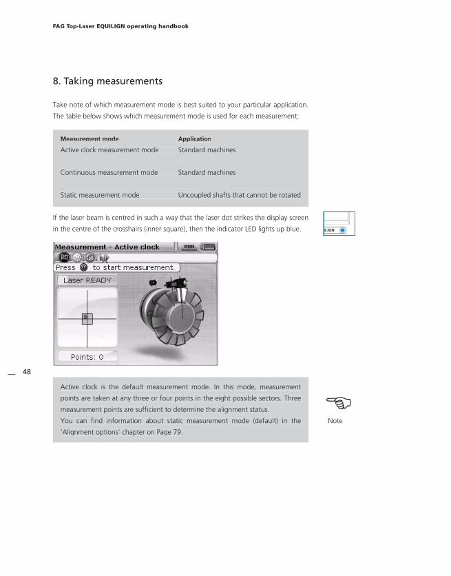
8. Taking measurements
Take note of which measurement mode is best suited to your particular application.
The table below shows which measurement mode is used for each measurement:
Measurement mode Application
Active clock measurement mode Standard machines
Continuous measurement mode Standard machines
Static measurement mode Uncoupled shafts that cannot be rotated
If the laser beam is centred in such a way that the laser dot strikes the display screen
in the centre of the crosshairs (inner square), then the indicator LED lights up blue.
Active clock is the default measurement mode. In this mode, measurement
points are taken at any three or four points in the eight possible sectors. Three
measurement points are sufficient to determine the alignment status.
You can find information about static measurement mode (default) in the
'Alignment options' chapter on Page 79.
Measurement mode Application
Active clock measurement mode Standard machines
Continuous measurement mode Standard machines
Static measurement mode Uncoupled shafts that cannot be rotated
ILIGN
HNote
Active clock is the default measurement mode. In this mode, measurement
points are taken at any three or four points in the eight possible sectors. Three
measurement points are sufficient to determine the alignment status.
You can find information about static measurement mode (default) in the
'Alignment options' chapter on Page 79.
Horizontal machine alignment
49
If coupling play (torsion play) is suspected, rotate the shafts once in the direction
of operation before measurement. Rotate the shaft or coupling end on which
the reflector is mounted. Ensure force is acting permanently on the coupling.
Covering the coupling with adhesive tape can prevent torsion play when the
shaft is rotating.
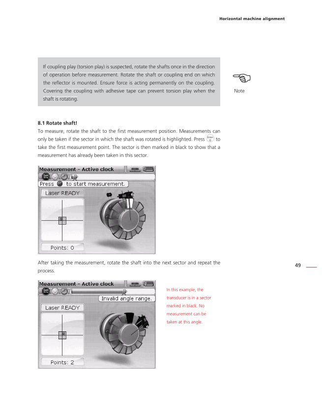
8.1 Rotate shaft!
To measure, rotate the shaft to the first measurement position. Measurements can
only be taken if the sector in which the shaft was rotated is highlighted. Press e to
take the first measurement point. The sector is then marked in black to show that a
measurement has already been taken in this sector.
After taking the measurement, rotate the shaft into the next sector and repeat the
process.
If coupling play (torsion play) is suspected, rotate the shafts once in the direction
of operation before measurement. Rotate the shaft or coupling end on which
the reflector is mounted. Ensure force is acting permanently on the coupling.
Covering the coupling with adhesive tape can prevent torsion play when the
shaft is rotating.
HNote
In this example, the
transducer is in a sector
marked in black. No
measurement can be
taken at this angle.

FAG Top-Laser EQUILIGN operating handbook
50
In active clock measurement mode, the electronic inclinometer in the transducer
is active and automatically sets the shaft rotation angle.
Make sure that you do NOT touch the measurement components (transducer,
reflector and chain-type bracket)!
Use the shaft to start its own rotation — do not use the chain-type bracket to
help gain momentum!
The shafts should be rotated in the normal direction of operation.
In continuous measurement mode, rotating the shafts or pressing the enter key
begins measurement, even if the laser beam is not adjusted to strike the centre
of the crosshairs exactly.
8.2 Laser end or Laser off? Extend the measurement range
The 'Laser end' or 'Laser off' messages indicate that the laser has drifted out of the
measurement range of the detector and no measurement values are being taken. You
can also use the optional ' Extend measurement range' function, which is described in
detail on page page 81.
The 'Extend measurement range' option is only available in active clock and static
measurement modes.
9. ResultsThe alignment results are opened automatically once the set number of measurement
points has been taken.
If, in active clock mode, the number of measurement points has been set to four,
the results can be accessed after three measurement points have been taken by
pressing k.
In active clock measurement mode, the electronic inclinometer in the transducer
is active and automatically sets the shaft rotation angle. HNoteMake sure that you do NOT touch the measurement components (transducer,
reflector and chain-type bracket)!
Use the shaft to start its own rotation — do not use the chain-type bracket to
help gain momentum!
The shafts should be rotated in the normal direction of operation.
In continuous measurement mode, rotating the shafts or pressing the enter key
begins measurement, even if the laser beam is not adjusted to strike the centre
of the crosshairs exactly.
The 'Extend measurement range' option is only available in active clock and static
measurement modes. HNote

Horizontal machine alignment
51
9.1 Alignment results in vertical and horizontal directions
Coupling results are given in the form of gap and offset values in horizontal and
vertical directions.
Sign convention
POSITIVE GAP: Opens at the top and away from the viewer.
POSITIVE OFFSET: If the machine on the right is higher or further away from the
viewer than the machine on the left.
If all four coupling values are within the tolerance, the machines do not need to
be aligned. If no in-house standards or specifications from the coupling or machine
manufacturer are available, the FAG Top-Laser EQUILIGN system provides a tolerance
check, shown by an indicator LED and the 'thumb' icon:
LED lights up blue: measured alignment within tolerance
LED lights up red: measured alignment outside tolerance
In the last two cases, the machines must be aligned.
If the coupling results indicate that the misalignment is too great, then the machine
must be shimmed vertically and/or moved horizontally to align it.
The vertical foot results
show that the back feet
on the right-hand machine
must be raised with a
0.45 mm shim.
HNote
Sign convention
POSITIVE GAP: Opens at the top and away from the viewer.
POSITIVE OFFSET: If the machine on the right is higher or further away from the
viewer than the machine on the left.

FAG Top-Laser EQUILIGN operating handbook
52
9.3 Tolerances
The 'thumb' icon on the display screen shows the degree to which the measured
alignment status lies within the tolerance. These foot tolerances are calculated from
the coupling tolerances. The 'thumb' icon indicates whether the alignment is within
or outside the tolerance.
The FAG Top-Laser EQUILIGN indicator LED provides further information on the
tolerance status.
Tolerance Thumb icon LED colour
within up green
outside down red
9.3 Tolerance table
It is possible to display the FAG Industrial Services GmbH tolerance table, which is only
valid for standard equipment running between 600 and 6000 RPM.
Suggested alignment tolerances are based upon experience and should not be
exceeded. They are to be used only if no in-house standards or specifications
from the coupling or machine manufacturer are available.
Information about opening the tolerance table can be found on page 93.
Within the tolerance
Outside the tolerance
Tolerance Thumb icon LED colour
within up green
outside down red
ILIGN
ILIGN
HNote
Suggested alignment tolerances are based upon experience and should not be
exceeded. They are to be used only if no in-house standards or specifications
from the coupling or machine manufacturer are available.
Horizontal machine alignment
53
10. Aligning the machine
The machines can now be aligned using the foot results. Remember that if all
feet lie within the tolerance range (indicator: thumbs up and the LED lights up
blue or green), then the machine does NOT need to be aligned.
To align your machine, move it vertically by shimming the feet and horizontally by
moving it to the side. These adjustments can be made in succession or simultaneously,
but following the procedure described below is recommended:
10.1 Shim first
We recommend shimming first, unless the horizontal corrective movement required is
significantly greater than that resolved by shims.
Shimming means lifting the machine and inserting or removing shims with a specified
thickness under its feet. FAG LASER-SHIMS are durable and labelled with their
thickness.
First move the machine horizontally if the horizontal correction required is very
large, as horizontal corrections move the feet to a different position on the base.
It is therefore possible that the machine may need to be checked for soft foot
again before continuing the alignment process.
10.1.1 Preparation
To shim the machine correctly, ensure the following:
1. Feet are clean, intact and mobile
2. Soft foot has been eliminated
3. There are enough shims under the machine to enable it to be lowered if
necessary
4. High-quality shims such as FAG LASER-SHIMS are available.
10.1.2 Loosen bolts
Avoid moving the machine horizontally. If one of the feet comes off the ground when
loosening the bolt, there is a soft foot problem.
The machines can now be aligned using the foot results. Remember that if all
feet lie within the tolerance range (indicator: thumbs up and the LED lights up
blue or green), then the machine does NOT need to be aligned.H
Note
First move the machine horizontally if the horizontal correction required is very
large, as horizontal corrections move the feet to a different position on the base.
It is therefore possible that the machine may need to be checked for soft foot
again before continuing the alignment process.
HNote

FAG Top-Laser EQUILIGN operating handbook
54
10.1.3 Shim feet
Use the vertical foot results to shim BOTH the front and back feet. Negative foot
values mean that shims must be added, while positive foot values mean shims must
be removed.
Vertical Live MOVE (real time movement) can also be used to move the machine
vertically.
10.1.4 Retighten bolts
The machines should now have good vertical alignment.
10.1.5 Measure again
Measure again to verify the shims and to determine the exact alignment status.
10.2 Horizontal Live MOVE
Horizontal MOVE is used to position the machine laterally. The conventional method
is to use dial gauges on the machine feet, but with the MOVE function, the horizontal
movement of the machine can now be followed in real time on the display screen.
10.2.1 Start horizontal Live MOVE
On the results screen, press e. The 'Results Options' screen opens.
Use the navigation keys to highlight the 'Move' icon, then press e to confirm the
selection. A screen opens to angle the shaft at any 45° position to the transducer.
HNote
Vertical Live MOVE (real time movement) can also be used to move the machine
vertically.

Horizontal machine alignment
55
10.2.2 Rotate shaft into a 45° position
Rotate the shaft into any 45° position (10:30, 1:30, 4:30 or 7:30 position as viewed
from the coupling towards the transducer).
If the laser is centred and the shaft is rotated into one of the green sectors, then the
screen to select the direction of movement will open automatically.
Use the h/i keys to highlight 'Horizontal' for horizontal machine movement.
Press e to confirm the selection. Live MOVE starts immediately.
FAG Top-Laser EQUILIGN operating handbook
56
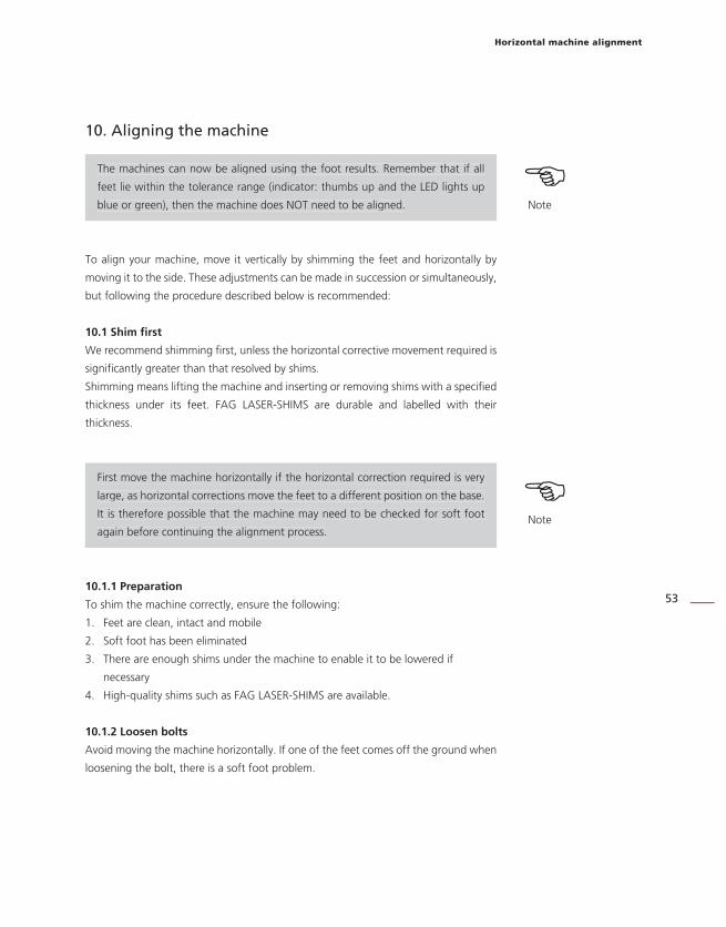
10.2.3 Loosen bolts and move the machine as shown
Loosen the foot anchor bolts and move the machine feet in the direction of the
yellow arrows, taking note of the thumb icon on the display screen. The movement
changes the arrow size automatically. Watch the display screen carefully to ensure
that the sides of the machine and direction of movement match. The thumb icon on
the display screen and the FAG Top-Laser EQUILIGN LED show the alignment status
while the machine is being moved.
Never attempt to move the machine with heavy blows from a sledgehammer, as
this will not only damage the measurement components but also lead to bearing
damage on the machine. Adjustable screws on the machine or other mechanical/
hydraulic aids are not only more convenient to use but also protect the materials.
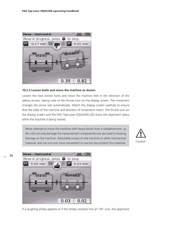
If a laughing smiley appears or if the smiley converts into an 'OK' icon, the alignment
Never attempt to move the machine with heavy blows from a sledgehammer, as
this will not only damage the measurement components but also lead to bearing
damage on the machine. Adjustable screws on the machine or other mechanical/
hydraulic aids are not only more convenient to use but also protect the materials.
aCaution
Horizontal machine alignment
57
status is within the tolerance. Press e to confirm the alignment status after
alignment correction.
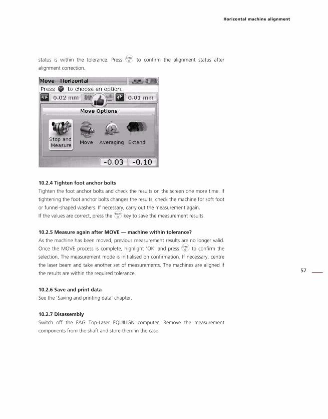
10.2.4 Tighten foot anchor bolts
Tighten the foot anchor bolts and check the results on the screen one more time. If
tightening the foot anchor bolts changes the results, check the machine for soft foot
or funnel-shaped washers. If necessary, carry out the measurement again.
If the values are correct, press the e key to save the measurement results.
10.2.5 Measure again after MOVE — machine within tolerance?
As the machine has been moved, previous measurement results are no longer valid.
Once the MOVE process is complete, highlight 'OK' and press e to confirm the
selection. The measurement mode is initialised on confirmation. If necessary, centre
the laser beam and take another set of measurements. The machines are aligned if
the results are within the required tolerance.
10.2.6 Save and print data
See the 'Saving and printing data' chapter.
10.2.7 Disassembly
Switch off the FAG Top-Laser EQUILIGN computer. Remove the measurement
components from the shaft and store them in the case.

FAG Top-Laser EQUILIGN operating handbook
58
Place the protective housing back on the machines before switching them back
on.
10.3 Vertical Live MOVE
For vertical Live MOVE, repeat steps 10.2.1 to 10.2.3 on the previous pages while
taking note of the vertical foot corrections.
10.4 Important points during the MOVE process
Follow points 10.4.1 to 10.4.5 closely during the MOVE process.
10.4.1 Has the shaft been moved by accident?
The shaft, transducer and reflector must NOT be moved for the duration of the MOVE
procedure! If the shaft moves from its set 45° position during the MOVE process, the
angle selection screen opens showing the current angle position for the shaft.
Place the protective housing back on the machines before switching them back
on. aCaution

Horizontal machine alignment
59
Live MOVE resumes automatically once the shaft is rotated back to its previous
45° position.
10.4.2 Laser end or Laser off? Extend the measurement range
The 'Laser end' or 'Laser off' messages indicate that the laser has drifted out of the
measurement range of the detector and no measurement values are being taken.
In this case, you can extend the measurement range during measurement. See the
'Alignment options' chapter, 'Extend measurement range' section on page 50.
10.4.3 Approaching zero value: Note the thumb icon and computer LEDs
Move the machine so that the values displayed for both machine ends approach zero
value. The colour of the computer LED changes from red (poor alignment) to green
(good alignment).
10.4.4 Soft foot
The effect of the MOVE function is affected by soft foot on the machine, resulting in
the machine changing its position every time the bolts are loosened and tightened.
For this reason, make sure to eliminate any soft feet before starting the alignment
process.
10.4.5 Do the measurement values deteriorate after alignment?
Possible causes:
› Brackets mounted incorrectly
› Brackets used to help rotate the shaft
› Significant play between couplings
› Soft foot can lead to positioning errors, meaning measurements need to be
taken again
› Loosened foot anchor bolts
› Yellow locking screws on the transducer loosened or reflector not secured
› Fluctuation in temperature: Has the machine only recently been shut down?
› Mounting: Have the laser and transducer been switched?
› Mounting: Has the transducer been rotated 180° when mounted (cable
pointing upwards)?
› Any vibrations?
HNote
Live MOVE resumes automatically once the shaft is rotated back to its previous
45° position.
Possible causes:
› Brackets mounted incorrectly
› Brackets used to help rotate the shaft
› Significant play between couplings
› Soft foot can lead to positioning errors, meaning measurements need to be
taken again
› Loosened foot anchor bolts
› Yellow locking screws on the transducer loosened or reflector not secured
› Fluctuation in temperature: Has the machine only recently been shut down?
› Mounting: Have the laser and transducer been switched?
› Mounting: Has the transducer been rotated 180° when mounted (cable
pointing upwards)?
› Any vibrations?

FAG Top-Laser EQUILIGN operating handbook
60
This page intentionally left blank.

Saving and printing data
61
11. Saving and printing data
Before switching the device off, please save all dimensions, measurements, results and
all settings in the device's non-volatile memory for use in analysis, future applications
or as measurement documentation.
The length of possible file names depends on the use of upper or lower case
letters.
11.1 Save the file
The measurement file currently in use can be saved at any time. Press q and
highlight the 'File' icon using the navigation keys.
Press e to confirm the selection. The file menu screen opens.
The length of possible file names depends on the use of upper or lower case
letters. HNote

FAG Top-Laser EQUILIGN operating handbook
62
Highlight the 'Save file' icon and press e to confirm the selection. An empty editing
box appears on the 'Save file' screen.
Use the data entry keys to enter the file name and press e to confirm the entry.
Measurement files can also be saved on the results screen after measurements have
been taken by pressing e on the results screen and using the navigation keys to
highlight the 'Save' icon.
Press e to confirm the selection. An empty editing box appears on the 'Save file'
screen. If a measurement file is being saved for the first time, then an empty editing
box appears. The file name can be entered using the data entry keys and confirmed
by pressing e. However, if the file has been saved once already, the editing box
appears containing the existing file name highlighted.
If the name contains both upper and lower case letters and
numbers, use o to cycle through these three options. Press
and hold down o while observing the indicator in the top
left corner of the editing box. The indicator switches between
the types of character that can currently be entered (upper
case, lower case or numbers). Spaces are entered by pressing
0.
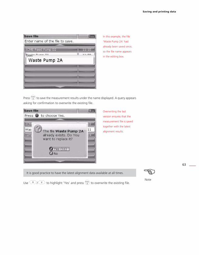
Saving and printing data
63
Press e to save the measurement results under the name displayed. A query appears
asking for confirmation to overwrite the existing file.
It is good practice to have the latest alignment data available at all times.
Use f/g to highlight 'Yes' and press e to overwrite the existing file.
It is good practice to have the latest alignment data available at all times. HNote
In this example, the file
'Waste Pump 2A' had
already been saved once,
so the file name appears
in the editing box.
Overwriting the last
version ensures that the
measurement file is saved
together with the latest
alignment results.

FAG Top-Laser EQUILIGN operating handbook
64
11.2 Print measurement reports
Measurement reports can be printed directly from the FAG Top-Laser EQUILIGN
computer on a printer using the 'LASER-EQUILIGN.USB-CABLE'.
There are various ways of printing measurement reports.
To print the current measurement report, press the q key and use the navigation
keys to highlight the 'File' icon.
Press e to confirm the selection. The file menu appears. Use the navigation keys to
highlight the 'Print report' icon.
Press e to confirm the selection. The 'Print report' screen opens.

Saving and printing data
65
FAG Top-Laser EQUILIGN offers three different printing options. Use the f/g
keys to highlight the required format.
Make sure that the FAG Top-Laser EQUILIGN computer is connected to the
printer via a USB cable and that the printer is fully configured. Follow section
'11.3 Printer configuration' if it is not configured.
Press e to print the measurement report for the selected measurement file.
Alternatively, the measurement report can be printed directly via the results screen
by pressing e on the results screen. The 'Results Options' screen opens. Use the
navigation keys to highlight the 'Print report' icon.
In this example, the
print option to print a
complete report has been
selected, containing both
graphics and text. The
selected printer is visible
in the header; in this case
'HPDeskJet450'.
Note that in FAG Top-Laser
EQUILIGN, the default
printed copy is a PDF file.
With this option selected,
the printed copy of the
measurement report is
saved automatically as a PDF
file. This file can then be
printed out on any printer
compatible with Windows.
See the 'Available print
options' section on Page
68.
HNote
Make sure that the FAG Top-Laser EQUILIGN computer is connected to the
printer via a USB cable and that the printer is fully configured. Follow section
'11.3 Printer configuration' if it is not configured.

FAG Top-Laser EQUILIGN operating handbook
66
Press e, to open the 'Print report' screen. Choose the format of the report, connect
the printer and print the report as described in the section above.
USB cable
LASER-EQUILIGN.USB
CABLE
The FAG Top-Laser
EQUILIGN computer
is connected to the
printer via the short USB
cable and the printer
USB cable. The printer
USB cable is a printer
accessory and is available
from most electronics
retailers.
Printer USB
cable
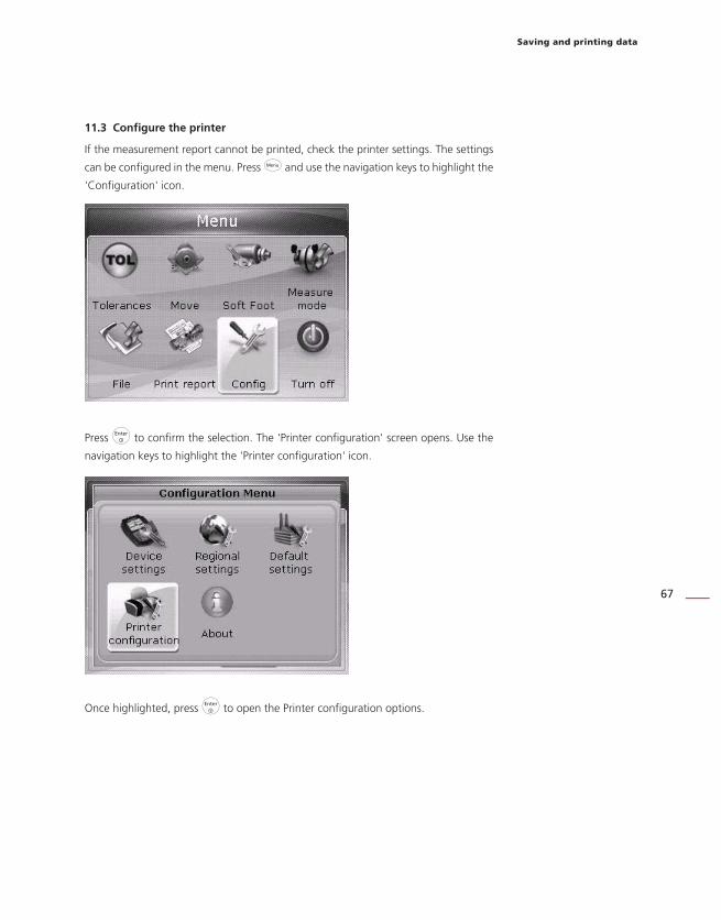
Saving and printing data
67
11.3 Configure the printer
If the measurement report cannot be printed, check the printer settings. The settings
can be configured in the menu. Press q and use the navigation keys to highlight the
'Configuration' icon.
Press e to confirm the selection. The 'Printer configuration' screen opens. Use the
navigation keys to highlight the 'Printer configuration' icon.
Once highlighted, press e to open the Printer configuration options.

FAG Top-Laser EQUILIGN operating handbook
68
11.4 Available printing options
The 'Printer configuration' screen shows the options available.
Use the f/g keys to highlight the option that you want to change. Press e.
A selection window opens with the available settings.
Use f/g to select
a printer. Highlight a
printer and press e to
confi rm the selection.
USB stick
LASER-EQUILIGN.
USB-CABLE
Grey USB connection

Saving and printing data
69
Measurement files can also be saved directly as PDF files by selecting the 'PDF file'
option, which enables files to be shared immediately and printed by any printer
compatible with Windows.
Use the f/g/0 keys to highlight 'PDF file' on the top line of the printer
selection.
If the selected printer configuration is ' PDF file', measurement reports from FAG
Top-Laser EQUILIGN can be saved directly as PDF files. Select one of the printing
options that was described in section 11.2. On the 'Print report' screen, use the
f/g keys to highlight the required report format.
Before confirming the saving process, ensure that the short FAG Top-Laser
EQUILIGN USB cable is inserted in the grey FAG Top-Laser EQUILIGN USB
connection and a FAG memory stick is connected to the short cable.
The FAG Top-Laser EQUILIGN directory on the memory stick should be empty to
prevent updates from being launched accidentally.
If 'PDF fi le' is selected,
press e to confi rm the
selection. Selecting this
printer confi guration
saves the measurement
report as a PDF fi le when
printing.
HNote
Before confirming the saving process, ensure that the short FAG Top-Laser
EQUILIGN USB cable is inserted in the grey FAG Top-Laser EQUILIGN USB
connection and a FAG memory stick is connected to the short cable.
The FAG Top-Laser EQUILIGN directory on the memory stick should be empty to
prevent updates from being launched accidentally.
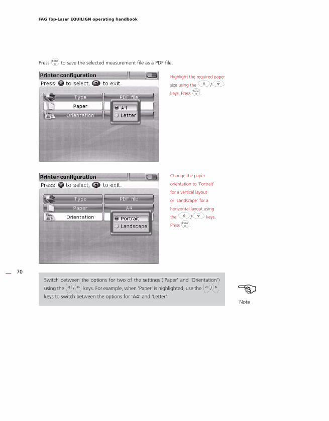
FAG Top-Laser EQUILIGN operating handbook
70
Press e to save the selected measurement file as a PDF file.
Switch between the options for two of the settings ('Paper' and 'Orientation')
using the h/i keys. For example, when 'Paper' is highlighted, use the h/i
keys to switch between the options for 'A4' and 'Letter'.
Highlight the required paper
size using the f/g
keys. Press e.
Change the paper
orientation to 'Portrait'
for a vertical layout
or 'Landscape' for a
horizontal layout using
the f/g keys.
Press e.
Switch between the options for two of the settings ('Paper' and 'Orientation')
using thehtwetw
/ien en
keys. For example, when 'Paper' is highlighted, use the htattat
/ion )on
keys to switch between the options for 'A4' and 'Letter'. HNote
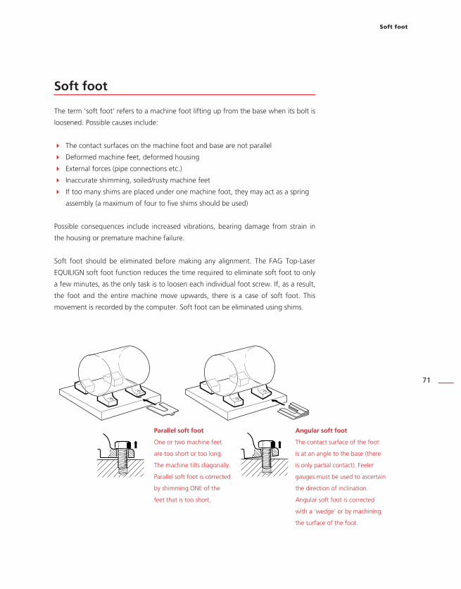
Soft foot
71
Soft foot
The term 'soft foot' refers to a machine foot lifting up from the base when its bolt is
loosened. Possible causes include:
The contact surfaces on the machine foot and base are not parallel
Deformed machine feet, deformed housing
External forces (pipe connections etc.)
Inaccurate shimming, soiled/rusty machine feet
If too many shims are placed under one machine foot, they may act as a spring
assembly (a maximum of four to five shims should be used)
Possible consequences include increased vibrations, bearing damage from strain in
the housing or premature machine failure.
Soft foot should be eliminated before making any alignment. The FAG Top-Laser
EQUILIGN soft foot function reduces the time required to eliminate soft foot to only
a few minutes, as the only task is to loosen each individual foot screw. If, as a result,
the foot and the entire machine move upwards, there is a case of soft foot. This
movement is recorded by the computer. Soft foot can be eliminated using shims.
Angular soft foot
The contact surface of the foot
is at an angle to the base (there
is only partial contact). Feeler
gauges must be used to ascertain
the direction of inclination.
Angular soft foot is corrected
with a 'wedge' or by machining
the surface of the foot.
Parallel soft foot
One or two machine feet
are too short or too long.
The machine tilts diagonally.
Parallel soft foot is corrected
by shimming ONE of the
feet that is too short.

FAG Top-Laser EQUILIGN operating handbook
72
Measuring and correcting soft foot conditions
There are three different types of soft foot: parallel, angular and induced soft foot.
In some instances, soft foot is a combination of two or more types. Checking for soft
foot is part of the preparatory work for alignment measurements.
Any machine to be measured typically has four feet in an approximately square
formation. If a machine has six feet, the measurement should be conducted in
two parts: first the four feet to the front, and then the four feet to the rear. Soft
foot is only measured on machines that are defined as movable and have been
provided with dimensions.
Start up the FAG Top-Laser EQUILIGN computer in the usual way, as described in the
'Getting started' chapter. Centre the laser beam as described in chapter '7.2.5 Laser
beam adjustment' on Page 45.
Rotate the shaft so that the transducer and reflector are either positioned at 3 o'clock
or 9 o'clock.
Enter the machine dimensions and then press . If the laser beam is not correctly
centred, the following screen appears:
Centre the laser beam as described in chapter '7.2.5 Laser beam adjustment' on
Page 45 or follow the instructions on-screen.
Any machine to be measured typically has four feet in an approximately square
formation. If a machine has six feet, the measurement should be conducted in
two parts: first the four feet to the front, and then the four feet to the rear. Soft
foot is only measured on machines that are defined as movable and have been
provided with dimensions.
HNote
The 'Soft foot' screen can
also be accessed via the
menu. Press the q key
and then use the navigation
keys to highlight the 'Soft
foot' icon. Press e to
confirm the selection.

Soft foot
73
Follow the instructions on-screen to centre the laser beam.
After pressing e, the laser beam adjustment help screen opens.
If soft foot has been measured in the order specified, then the laser beam
adjustment help screen appears automatically and does not need to be opened.
Follow the instructions on-screen and adjust the laser beam by rotating the adjustment
screw or the yellow adjustment knob.
Centre the laser beam and press the e or ß key.
In this example, the
instructions on-screen show
that e must be pressed
in order to open the laser
beam adjustment help
screen.
HNote
If soft foot has been measured in the order specified, then the laser beam
adjustment help screen appears automatically and does not need to be opened.

FAG Top-Laser EQUILIGN operating handbook
74
If the laser beam has already been centred during set up, the following screen
appears:
If not all dimensions have been entered into the dimensions screen, the following
screen appears:
HNote
If the laser beam has already been centred during set up, the following screen
appears:
If not all dimensions have been entered into the dimensions screen, the following
screen appears: HNote
Use the f/g
keys to highlight 'Yes' and
press e to confirm the
selection.
The dimensions screen
reappears so that the
missing values can be
entered.

Soft foot
75
If the shaft has not been positioned correctly at 3 o'clock or 9 o'clock, the following
screen appears:
Rotate the shaft to the correct 3 o'clock or 9 o'clock position (green segments in the
circle) and continue the measurement process.
If the message 'Angle
ok' appears, press either
e or ß to continue
the measurement process
or wait until the process
continues automatically.
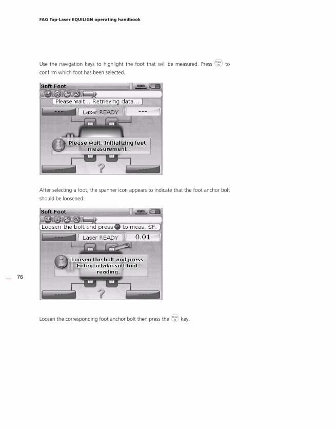
FAG Top-Laser EQUILIGN operating handbook
76
Use the navigation keys to highlight the foot that will be measured. Press e to
confirm which foot has been selected.
After selecting a foot, the spanner icon appears to indicate that the foot anchor bolt
should be loosened:
Loosen the corresponding foot anchor bolt then press the e key.

Soft foot
77
Loosen the corresponding foot anchor bolt. The measured distance by which the foot
has lifted is shown on the screen.
Press e to save the value and display it on the screen permanently. Retighten the
foot anchor bolt. The next foot is highlighted automatically. Any other foot can be
highlighted as required using the navigation keys.
Repeat the process for each foot. Use the navigation keys to highlight the next foot.
Corrections for the feet are calculated with the four foot values. Please note that
these values are saved together with the dimensions, measurements and results in the
measurement file and also appear in the measurement report.
The default foot tolerance is
0.06 mm. If any single foot
exceeds this tolerance, a
'thumbs down' icon appears
immediately.

FAG Top-Laser EQUILIGN operating handbook
78
Parallel soft foot — correction
Parallel soft foot is present if two large values and two small values are diagonally
opposite to each other. The machine rests on both of the higher feet and tilts towards
the lower feet.
Angular soft foot — correction
If one individual foot value is considerably higher than the others, it is called angular
soft foot.
To correct angular soft foot, the direction in which the soft foot is angled must first be
determined by loosening the foot bolt and using feeler gauges.
If the soft foot is 'purely' angular, the shim value will range from zero to twice the
thickness displayed. A graduated shim will eliminate angular soft foot.
Parallel soft foot
In the example shown
here, 89-100 mm shims are
inserted under foot 'b' (the
foot with the highest value)
— just like putting a beer
mat under the shortest leg
of a wobbly table!
dc
ba
c 0.74
b 0.89
d 0.10
a 0.18
Angular soft foot
If one individual foot value
is considerably higher
than the others, it is called
angular soft foot.
Example values in mm
dc
ba
c 0.76
b 0.13
d 0.10
a 0.18

Alignment options
79
Alignment options
Measurement modes
FAG Top-Laser EQUILIGN provides both active clock and static (0369) as default
measurement modes.
All measurement modes can be accessed via the menu screen. Press the q key to
open the menu screen. Use the navigation keys to highlight the 'Measure mode' icon
on the menu screen.
Press e to confirm the selection.
Use the navigation keys to highlight the required measurement mode and press e
to confirm the selection.
The 'Measurement Options'
screen can only be accessed
if all necessary machine
data has been entered in
the measurement file that
is currently open.
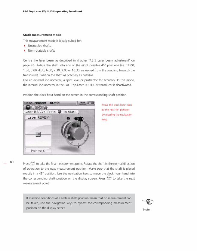
FAG Top-Laser EQUILIGN operating handbook
80
Static measurement mode
This measurement mode is ideally suited for:
Uncoupled shafts
Non-rotatable shafts
Centre the laser beam as described in chapter '7.2.5 Laser beam adjustment' on
page 45. Rotate the shaft into any of the eight possible 45° positions (i.e. 12:00,
1:30, 3:00, 4:30, 6:00, 7:30, 9:00 or 10:30, as viewed from the coupling towards the
transducer). Position the shaft as precisely as possible.
Use an external inclinometer, a spirit level or protractor for accuracy. In this mode,
the internal inclinometer in the FAG Top-Laser EQUILIGN transducer is deactivated.
Position the clock hour hand on the screen in the corresponding shaft position.
Press e to take the first measurement point. Rotate the shaft in the normal direction
of operation to the next measurement position. Make sure that the shaft is placed
exactly in a 45° position. Use the navigation keys to move the clock hour hand into
the corresponding shaft position on the display screen. Press e to take the next
measurement point.
If machine conditions at a certain shaft position mean that no measurement can
be taken, use the navigation keys to bypass the corresponding measurement
position on the display screen.
Move the clock hour hand
to the next 45° position
by pressing the navigation
keys.
If machine conditions at a certain shaft position mean that no measurement can
be taken, use the navigation keys to bypass the corresponding measurement
position on the display screen. HNote
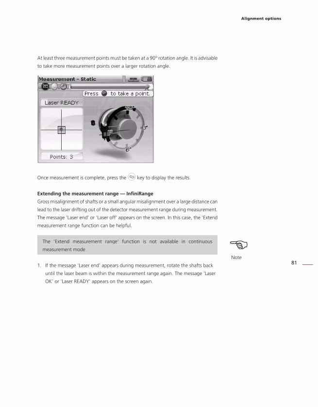
Alignment options
81
At least three measurement points must be taken at a 90° rotation angle. It is advisable
to take more measurement points over a larger rotation angle.
Once measurement is complete, press the k key to display the results.
Extending the measurement range — InfiniRange
Gross misalignment of shafts or a small angular misalignment over a large distance can
lead to the laser drifting out of the detector measurement range during measurement.
The message ' Laser end' or 'Laser off' appears on the screen. In this case, the 'Extend
measurement range function can be helpful.
The 'Extend measurement range' function is not available in continuous
measurement mode.
1. If the message 'Laser end' appears during measurement, rotate the shafts back
until the laser beam is within the measurement range again. The message 'Laser
OK' or 'Laser READY' appears on the screen again.
The 'Extend measurement range' function is not available in continuous
measurement mode. HNote

FAG Top-Laser EQUILIGN operating handbook
82
2. Press q, to open the menu. Use the navigation keys to highlight the
'Measurement mode' icon on the menu screen and press e to confirm
the selection. The 'Measurement Options' screen opens.
3. Use the navigation keys to highlight the 'Extend' icon on the 'Measurement
Options' screen and press e to confirm the selection. The computer interrupts
the measurement and switches to the laser beam adjustment screen. The current
beam position is recorded automatically and is used as the starting point for
extending the measurement range.

Alignment options
83
4. Re-adjust the laser beam to strike the target box using the yellow adjustment
knob and the thumbwheel on the side of the reflector.
5. Once you have centred the laser point, the LED on the computer lights up blue.
The set laser beam position is recorded and automatically becomes the end point
for laser beam deviation.
6. Continue the measurement as previously described. Rotate the shafts and press
e to take measurement values at each of the required measurement positions.
The computer considers the laser beam readjustment in all further alignment
calculations.
ILIGN

FAG Top-Laser EQUILIGN operating handbook
84
The message 'Laser end' is displayed if the reflected laser beam does not strike
the detector. This situation arises when machines are extremely misaligned or if
the measurement paths are too long. No measurements can be taken while this
message is displayed.
Averaging
In certain alignment situations, the average must be taken from a high number of
measurement values to reach the level of accuracy required. Particular cases include
industrial facilities that are exposed to increased machinery vibrations. An increased
average also improves accuracy when measuring plain bearings, white metal bearings
and journal bearings.
The number of individual measurements needed for the averaged measurement
is set on the 'Measurement Options' screen. Press q to open the menu.
Use the navigation keys to highlight the 'Measurement mode' icon on the menu
screen and press e to confirm the selection. The 'Measurement Options' screen
opens.
Use the navigation keys to highlight the 'Averaging' icon, then press e to confirm
the selection.
The message 'Laser end' is displayed if the reflected laser beam does not strike
the detector. This situation arises when machines are extremely misaligned or if
the measurement paths are too long. No measurements can be taken while this
message is displayed.
HNote

Alignment options
85
The setting options for calculating the average range from 0.4 seconds (smallest
value) to 1.6 seconds (largest value).
Calculating an average is possible in the 'static measurement mode'. The selected
setting for the average is also valid for measuring soft foot and for Live MOVE. If
a higher average is selected (e.g. 1.6 seconds), more time and patience must be
exercised when taking the measurements to allow the FAG Top-Laser EQUILIGN
computer to 'catch up' with machine movement (MOVE). In this instance, it
takes 1.6 seconds to take each measurement needed to update the graphical
format!
HNote

FAG Top-Laser EQUILIGN operating handbook
86
This page intentionally left blank.
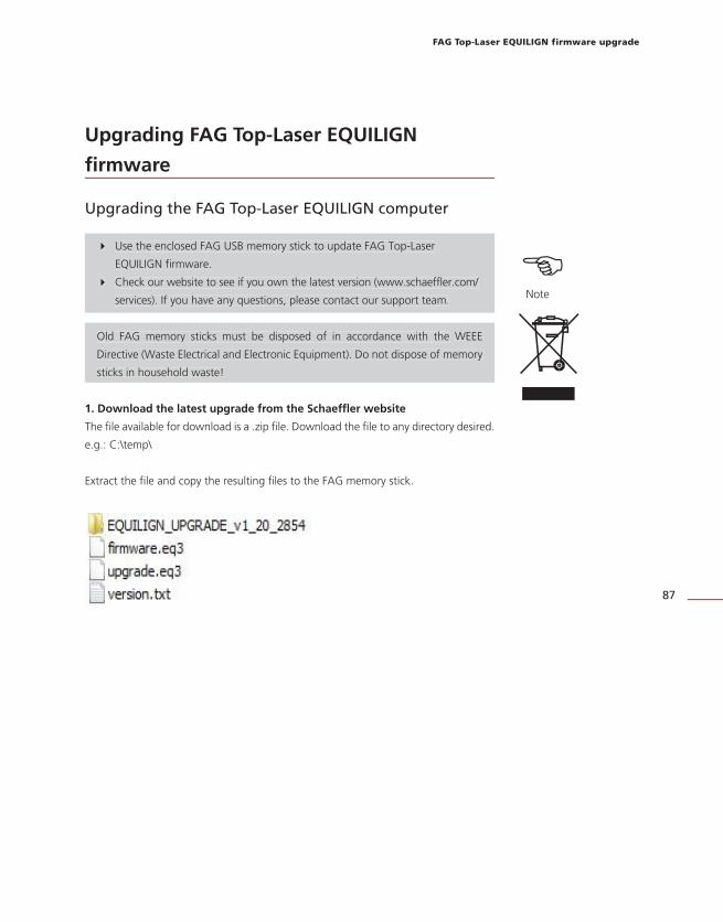
87
FAG Top-Laser EQUILIGN firmware upgrade
Upgrading FAG Top-Laser EQUILIGN
firmware
Upgrading the FAG Top-Laser EQUILIGN computer
Use the enclosed FAG USB memory stick to update FAG Top-Laser
EQUILIGN firmware.
Check our website to see if you own the latest version (www.schaeffler.com/
services). If you have any questions, please contact our support team.
Old FAG memory sticks must be disposed of in accordance with the WEEE
Directive (Waste Electrical and Electronic Equipment). Do not dispose of memory
sticks in household waste!
1. Download the latest upgrade from the Schaeffler website
The file available for download is a .zip file. Download the file to any directory desired.
e.g.: C:\temp\
Extract the file and copy the resulting files to the FAG memory stick.
HNote
Use the enclosed FAG USB memory stick to update FAG Top-Laser
EQUILIGN firmware.
Check our website to see if you own the latest version (www.schaeffler.com/
services). If you have any questions, please contact our support team.
Old FAG memory sticks must be disposed of in accordance with the WEEE
Directive (Waste Electrical and Electronic Equipment). Do not dispose of memory
sticks in household waste!
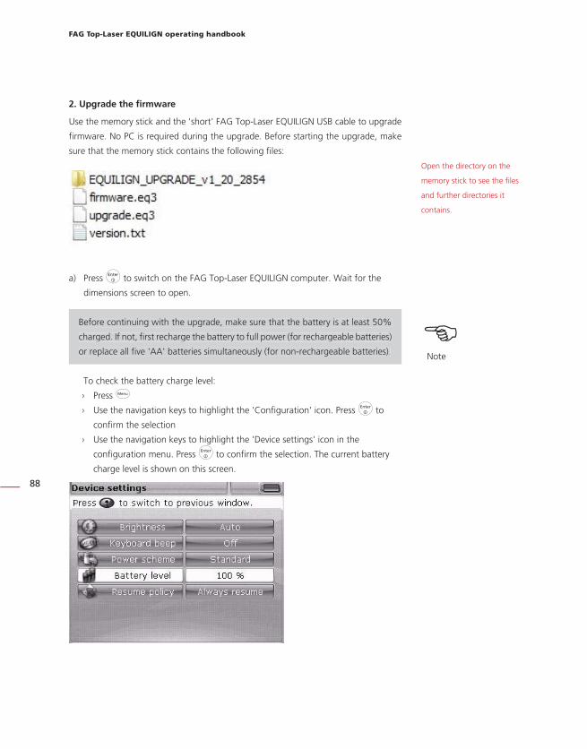
FAG Top-Laser EQUILIGN operating handbook
88
2. Upgrade the firmware
Use the memory stick and the 'short' FAG Top-Laser EQUILIGN USB cable to upgrade
firmware. No PC is required during the upgrade. Before starting the upgrade, make
sure that the memory stick contains the following files:
a) Press e to switch on the FAG Top-Laser EQUILIGN computer. Wait for the
dimensions screen to open.
Before continuing with the upgrade, make sure that the battery is at least 50%
charged. If not, first recharge the battery to full power (for rechargeable batteries)
or replace all five 'AA' batteries simultaneously (for non-rechargeable batteries).
To check the battery charge level:
› Press q › Use the navigation keys to highlight the 'Configuration' icon. Press e to
confirm the selection
› Use the navigation keys to highlight the 'Device settings' icon in the
configuration menu. Press e to confirm the selection. The current battery
charge level is shown on this screen.
Open the directory on the
memory stick to see the files
and further directories it
contains.
HNote
Before continuing with the upgrade, make sure that the battery is at least 50%
charged. If not, first recharge the battery to full power (for rechargeable batteries)
or replace all five 'AA' batteries simultaneously (for non-rechargeable batteries).

89
FAG Top-Laser EQUILIGN firmware upgrade
b) Insert the 'short' FAG Top-Laser EQUILIGN USB cable into the grey USB port on
the FAG Top-Laser EQUILIGN computer.
c) Once it has been checked, connect the FAG memory stick to the 'short' USB cable.
d) A message appears saying new firmware is available and that the FAG Top-Laser
EQUILIGN computer must be re-started.
e) When the message shown above appears, press and hold e to restart the
computer. The display will also switch off.
f) After a short time (approx. 10 seconds), the upgrade process starts
automatically. The computer beeps and the alignment status indicator LED
flashes when the process starts.

FAG Top-Laser EQUILIGN operating handbook
90
Do NOT remove the memory stick from the computer and do NOT switch the
computer off during the upgrade (duration approx. 4 minutes).
g) Shortly before the upgrade process ends, the screen below appears. The dimensions
screen is displayed shortly afterwards.
HNote
Do NOT remove the memory stick from the computer and do NOT switch the
computer off during the upgrade (duration approx. 4 minutes).

91
FAG Top-Laser EQUILIGN firmware upgrade
HNote
h) Once the dimensions screen has appeared, press q. Use the navigation keys
to highlight the 'Configuration' icon. When the icon is highlighted, press e to
open the configuration menu.
i) Use the navigation keys to highlight the 'Details' icon. When the icon is
highlighted, press e to confirm the selection. The 'Details' screen opens.
The USB cable can now be removed from the FAG Top-Laser EQUILIGN computer.
The new firmware version
on the FAG Top-Laser
EQUILIGN computer is
now ready to use and
can be found on the
'Application details' screen.
The current application
build, the number of
functions installed and
further information is also
displayed.
HNote
The USB cable can now be removed from the FAG Top-Laser EQUILIGN computer.

FAG Top-Laser EQUILIGN operating handbook
92
This page intentionally left blank.

Appendix
93
Appendix
Recommended alignment tolerances
[RPM] Metric
[mm]
Imperial
[mils]
Soft foot All 0.06 mm 2.0 mils
Short 'flexible'
couplings
Offset
Good Good
600 9.0
750 0.19
900 6.0
1200 4.0
1500 0.09
1800 3.0
3000 0.06
3600 1.5
6000 0.03
7200 1.0
Angular offset (gap)
Width of gap per
100 mm coupling
diameter
600 15.0
750 0.13
1500 0.07
1800 5.0
3000 0.04
3600 3.0
6000 0.03
7200 2.0
[continued]

FAG Top-Laser EQUILIGN operating handbook
94
[RPM] Metric
[mm]
Imperial
[mils]
Good Good
Spacer shafts and
membrane (disc)
couplings
Offset
(per 100 mm
spacer shaft length)
600 3.0
750 0.25
1500 0.12
1800 1.0
3000 0.07
3600 0.5
6000 0.03
7200 0.3
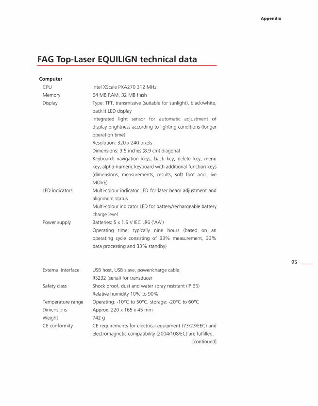
Appendix
95
FAG Top-Laser EQUILIGN technical data
Computer
CPU Intel XScale PXA270 312 MHz
Memory 64 MB RAM, 32 MB flash
Display Type: TFT, transmissive (suitable for sunlight), black/white,
backlit LED display
Integrated light sensor for automatic adjustment of
display brightness according to lighting conditions (longer
operation time)
Resolution: 320 x 240 pixels
Dimensions: 3.5 inches (8.9 cm) diagonal
Keyboard: navigation keys, back key, delete key, menu
key, alpha-numeric keyboard with additional function keys
(dimensions, measurements, results, soft foot and Live
MOVE)
LED indicators Multi-colour indicator LED for laser beam adjustment and
alignment status
Multi-colour indicator LED for battery/rechargeable battery
charge level
Power supply Batteries: 5 x 1.5 V IEC LR6 ('AA')
Operating time: typically nine hours (based on an
operating cycle consisting of 33% measurement, 33%
data processing and 33% standby)
External interface USB host, USB slave, power/charge cable,
RS232 (serial) for transducer
Safety class Shock proof, dust and water spray resistant (IP 65)
Relative humidity 10% to 90%
Temperature range Operating: -10°C to 50°C, storage: -20°C to 60°C
Dimensions Approx. 220 x 165 x 45 mm
Weight 742 g
CE conformity CE requirements for electrical equipment (73/23/EEC) and
electromagnetic compatibility (2004/108/EC) are fulfilled.
[continued]

FAG Top-Laser EQUILIGN operating handbook
96
Transducer
Details Measurement principle: coaxial, reflected laser beam
Safety class: IP 67 (resistant to dust and immersion in water)
Protection from ambient light: yes
Storage temperature: -20°C to 80°C
Operating temperature: 0°C to 55°C
Dimensions: approx. 107 x 70 x 49 mm
Weight: approx. 177 g
Laser Type: Ga-Al-As diode laser
Typical wavelength 675 nm (red, visible)
Safety class: Class 2, FDA 21 CFR 1000 and 1040
Beam power: < 1 mW
Safety instruction: Do not look into the laser beam!
Detector Measurement range: any, dynamically extendable
(U.S. Patent 6,040,903)
Resolution: 1 micrometre
Accuracy (average): > 98%
Inclinometer Measurement range: 0°-360°
Resolution: <1°
Reflector
Details Type: 90° roof prism
Accuracy (average): > 99%
Safety class: IP 67 (resistant to dust and immersion in water)
Storage temperature: -20°C to 80°C
Operating temperature: -20°C to 60°C
Dimensions: approx. 100 x 41 x 35 mm
Weight: approx. 65 g
Transport case
Details Standard: ABS
Case dimensions: approx. 500 x 410 x 140 mm
Weight, including all standard parts: approx. 4.1 kg

Appendix
97
EC Declaration of Conformity

FAG Top-Laser EQUILIGN operating handbook
98
This page intentionally left blank

Index
99
Index
A
Active clock 30, 48Advanced mode 11, 41Angular soft foot 71
correcting 78Application details 25Auto flow 11, 41Averaging 84
B
Batteries 13Battery level 19Battery replacement 12Bracket
Compact chain-type bracket 16
Compact magnetic bracket 16Brackets 15
C
CE compliance 7CE conformity 97Chain-type bracket 15
mounting 36Coupling play 35, 49Coupling results 51
D
Data management 26Data storage 9Default measuring mode 30Default settings 24Device settings 18Display brightness 18
E
Editing box 30, 42Electromagnetic compatibility 7Extend the measurement range 50, 59
F
File
open 27
resume 26
save 27
saving 61Firmware upgrade 87
H
Horizontal Live MOVE 54
I
Imprint 1InfiniRange 81Interfaces 9IP classification 7
L
Language 21Laser
ANSI standard 8
FDA specification 8
Protection class 2 8Laser beam
centring 45Laser end 81Laser safety class 8LED
Alignment status 11, 46
Battery charge level 11Lens cleaning cloth 14Live MOVE
horizontal 54
vertical 58
M
Marking
for distance measurement 42Measurement mode 48, 79Measurement reports
printing 64Memory stick 69
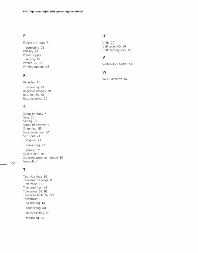
FAG Top-Laser EQUILIGN operating handbook
100
P
Parallel soft foot 71
correcting 78PDF file 69Power supply
setting 19Printer 25, 67Printing options 68
R
Reflector 15
mounting 39Regional settings 20Resume 26, 28Resume policy 20
S
Safety symbols 7Save 27Saving 61Scope of delivery 5Shimming 53Sign convention 51Soft foot 71
angular 71
measuring 72
parallel 71Spacer shaft 94Static measurement mode 80Symbols 7
T
Technical data 95Temperature range 8Time zone 21Tolerance icon 33Tolerances 52, 93Tolerance table 52, 93Transducer
calibrating 14
connecting 40
disconnecting 40
mounting 38
U
Units 20USB cable 65, 88USB memory stick 88
V
Vertical Live MOVE 58
W
WEEE Directive 87

Index
101
FAG Industrial Services GmbHKaiserstrasse 10052134 HerzogenrathGermanyTel: +49 (0) 2407 9149 66Fax: +49 (0) 2407 9149 [email protected]/services
Support:Tel: +49 (0) 2407 9149 [email protected]

FAG Top-Laser EQUILIGN operating handbook
102
This page intentionally left blank.