Embed Size (px)
Citation preview

NEAR EAST UNIVERSITY
Faculty of Engineering
Department of Computer Engineering
ANALYSIS OF ETHERNET, TOKEN RING AND FDDI TECHNOLOGIES
GRADUATION PROJECT COM-400
(
Student: Muhammad Yousaf Ismail (980004)
Supervisor: Prof. Dr. Fakhraddin Mamedov
, Nicosia - 2002

ACKNOWLEDGEMENTS •
First of all I would like to thank ALMIGHTY ALLAH for the courage, He
gave me for the completion of my Project and Computer Engineering.
Second I would like to thank my honorable supervisor Prof. Dr. Fakhreddin
Sadikoglu Mamedov, present Dean Of Faculty Of Engineering for his invaluable
advice and belief in my work. Under his guidance, I successfully overcome many
difficulties and learn a lot about Ethernet, Token Ring and FDDI technologies. In each
discussion, he explained my questions patiently and answered my questions in detail.
Special thanks to my friends in NEU: Asif, Ashraf, Ayoub, Al Haaj, Fatih,
Kadime, Mehmet, Munawer, Yucel and Yasir. For their constant encouragement and
advice during the preparation of this project.
Finally I want to thank my family, especially my uncle Ibraheem, my sisters
Fouzia, Zainab, Merriam, my brother M Younas Ismail and my dear parents. Without
their endless support and love for me, I would never achieve my current position. I wish
them very long life and happiness in their future life.
l
ABSTRACT •
Ethernet Uses a bus or star topology and relies on the form of access known as Carrier
Sense Multiple Access with Collision Detection to regulate communication line traffic.
Network nodes are linked by a coaxial-cable, by fiber-optic cable or by twisted-pair
wiring. The Ethernet Standard provides for base band transmission at 10 Mbps.
A unique structure object or message that circulate continuously among the nodes of a
Token ring and describe the current state of the network. Before any node can send a
message, it must first wait to control the token. A Local Area Network (LAN) in a ring
topology that use token passing to regulate traffic on the line. On a token ring network a
token governing the right to transmit is passed from one station to the next in a physical
circle. A station with information to transmit "sizes" the token, marks it as being in use,
and inserts the information. The "busy" token, plus message, is then passed around the
circle, copied at its destination, and eventually returned to the sender. The sender
removes the attached message and then passes the freed token to the next station in line.
FDDI (Fiber Distributed Data Interface) is a high-performance fiber-optic token ring
LAN running at 100 Mbps over distance up to 200 km with up to 1000 stations
connected. FDDI uses multimode fiber because the additional expense of single mode
fiber is not needed for networks at only 100 Mbps. The FDDI cabling consist of two
fiber Rings , one transmitting clockwise and other transmitting counter clockwise.
11

TABLE OF CONTENTS
ACKNOWLEDGMENT
ABSTRACT
TABLE OF CONTENTS
LIST OF ABBREVIATIONS
INTRODUCTION CHAPTER ONE: NETWORKING TECHNOLOGIES
1. NETWORKING TECHNOLOGIES
1.1. Local Area Networks (LAN)
1.2. Metropolitan Area Networks (MAN)
1.3. Wide Area Networks (WAN)
CHAPTER TWO: ANALYSIS OF ETHERNETS
1
11
iii
vu
1
2
2
3
3
2.1. ETHERNET 4
2.2. Ethernet Cabling 4
2.3. EWTIA Wiring Standard 6
2.4. Uses For High Transmission Speeds 6
2.5. Medium Dependent Interface 7
2.6. Physical Medium 7
2.7. Medium Attachment Unit 7
2.8. CSMA/CD Technology 8
2.8.1. Collision 9
2.8.2. Late Collision 10
2.8.3. Excessive Collisions 11
CHAPTER THREE : CLASSES OF ETHERNET CARDS
3. 1. TRADITIONAL ETHERNET CARDS 12
3 .1.1. 10Base5 12
3.1.2. 10Base2 13
3.1.3. 10 Base T 15
3.1.4. 10 Base F 16
3.1.5. 5-4-3 Rule 17
3.2. FAST ETHERNET (802.3U) 18
3.2.1. Easy To Install And Use 1 19
3 .2.2. Preserves Your Wiring Investment 19
iii

3.3.1. lOOBaseTx
3.3.2. 100BaseT4
3.3.3. lOOBaseFL
3.3.4. 100BaseT2
3.4. GIGABIT ETHERNET
3.4.1. lOOOBaseX (802.3z)
3.4.2. lOOOBaseT (802.3ab)
3.4.3. lOOOBaseCX.
3.5. Ethernet Autoprobing
3.6. Components
3 .6.1. Media Access Control (MAC) Layer
3.6.2. Media Independent Interface (MII) Layer
3.6.3. I/G and U/L within the MAC address
3.7. Frame Formats
3.7.1. Subnetwork Access Protocol (SNAP)
3.7.2. Frame Check Sequence (FCS) Error
3.7.3. Signal Quality Error (SQE)
3.7.4. Inter Packet Gap (IPG)
3.7.5. Propagation Delay
3.7.6. Alignment Error
3. 7. 7. Promiscuous Mode
3.8. Error Conditions
3.9. Network Diameter
3.10. Connectivity Rules
3 .10.1. Rules for Network Expansion
3.11. Full-Duplex
3.12. Half-Duplex
3.13. Jam
3.14. Broadcast Storm
3.15. Topology
3.16. Basic Rules
3.17. Switches 3 .17 .1. Micro segmentation and Switching
• 19
20
21
22
22
22
23
23
24
26
26
27
27
27
29
32
32
32
32
32
33
33
34
34
34
36
36
37
41
41
42
43
43
IV

3.17.2. Dedicated, Switched Ethernet Segments
3.17.3. Switched 10 Versus Shared 100
3 .18. Repeaters
3.18.1. Repeater Classes
3.19. A Sample Integration Scenario
3.20. Techniques for Improving Performance
3 .21 List of Ethertypes
CHAPTERFOUR:TOKENRING
4.0. Token Ring
4.1. The Basic 4.2. Token Ring Self Maintenance
4.3. Token Ring Operation using a Hub
4 .4. History
4.5. Ring benefits:
4.6. Token Ring Mechanism
4.6.1. Early Token Release mechanism (ETR)
4.7.Token Ring/IEEE 802.5
4.8. Topology Media
4.9. Token Format
4.9.1. Starting Delimiter Format
4.9.2. Access Control Format:
4.9.3. P = Priority 4.9.4. M = Monitor
4.9.5. R:::: Reserved bits
4.9.6. Ending Delimiter Format
4.9.7 .. Frame Format
4.10. Ring Management
4.11. Fault Management
4.12. Active Monitor Duties
4.12.1. Standby Monitor Duties
4.12.2. Ring Poll
4.12.3. Ring Purge
4.12.3.1. Claim Token Process
V
• 43
44
46
47
48
48
49
51
51
53
54
54
55
56
56
57
57
58
58
58
59
59
59 59
59
60
61
61
62
62
63
63

4.13. Bypassing a Failed Station 63
4.14. Physical Connections 64
4.15. Token Ring Architectural Model 65
4.16. Beacon 66
4.16.1. Ring insertion 67
4.17. Hardware error 67
4.18. Characteristics 68
4.19. Summary 69
CHAPTER FIVE: FIBER DISTRIBUTED DATA INTERFACE ( FDDI)
5.0. Fiber Distributed Data Interface ( FDDI) 70
5 .1. PERFORMANCE OF FDDI 72
5.2. Frame Format 74
5.2.l Tokens Mechanism 76
5.3. FDDI - Self healing 76
5.4. Physical Layer Components 76
5.5. STATION TYPES AND NETWORK TOPOLOGIES 77
5.6. Single-Attachment Station 77
5.7. Station Management Component 77
5.8. Dual-Attachment Concentrator 78
5.9. FDDI ARCHITECTURAL MODEL 80
5.10. Ring Monitoring Functions 80
5.11. Claim Token Procedure 81
5.12. Ring Initialization 81
5 .13. Beacon Process 82
5.14. Wideband Channels 82
5.15. FDDI II 82
5.16. Isochronous Transmission 83
5.17. Basic and Hybrid Operation 83
5.18. Optional FDDI MAC Protocol Features 84
5.18.1. Interconnecting FDDI and Ethernet LANs 84
5 .19. Future Direction 84
5.20. Summary 85
CONCLUSION 86
REFERENCES 88
vi

CCB.
CSMAICD.
DAC.
DNA.
DQDB.
ETR.
ELAP.
FCS.
FDDI.
FOIRL.
IEEE.
IPG.
LAN.
MAC.
MACSDU.
MAN.
MIC.
MIi.
NAC.
NFS.
NIC.
PPP.
SAC
SNA.
SNAP.
SNMP.
SQE.
TLAP.
WAN.
LIST OF ABBREVIATIONS •
Command control block. Carrier sense multiple access with collision detection.
Dual-attachment concentrator.
Digital Network Architecture.
Distributed Queue Dual Bus.
Early Token Release mechanism
EtherTalk Link Access Protocol.
Frame check sequence.
Fiber Distributed Data Interface.
Fiber-Optic Inter-Repeater Link.
Institute of Electrical and Electronics Engineers.
Inter Packet Gap.
Local area network.
Medium Access Control.
Medium-access-control-service-data-unit.
Metropolitan Area Network.
Medium interface connector.
Media Independent Interface Layer.
Null-attachment concentrator.
Network File System.
Network interface card.
Point-to-Point Protocol.
Single-attachment concentrator.
Systems Network Architecture.
Sub network Access Protocol.
Simple Network Management Protocol.
Signal Quality Error.
Token Talk Link Access Protocol.
Wide area network.
vii

Introduction
Effective use of computer systems demands that the user has the ability to
move data between devices reliably. In a very simple example we must be able to print
from a PC (personal computer) to an attached printer without any errors occurring as the
data is transferred. This can be considered as a two-stage activity Firstly the data must
be correctly sent and received. Secondly the sending device must know that it has been
correctly received. If, during this second stage, the sender is informed that it has not
been correctly received and the transfer was unsuccessful, then an attempt to put matters
right and recover from the error is undertaken. The whole concept of data
communication is based on these basic principles of sending data, checking its correct
receipt and confirming how successful the transfer was. The designs which have
evolved to manage this approach are known as protocols i.e. who says what and when!
At the simplest level there may be two devices that are directly connected. At more
advanced levels they may be connected either by a telephone line or a full-blooded
network and be separated by thousands of miles.
The design, installation, and operation of computer networks is vital to the
functioning of modem computerized organizations. Over the last decade, organizations
have installed complex and diverse networks, tying together mainframes,
minicomputers, personal computers, workstations, terminals, and other devices.
The objective of this project is to investigate the development of Ethernets,
Token Ring and FDDI technologies and compare the differences in all the aspects of
performance i.e. Data Transfer Speed, Security, Reliability with least expense.
In this project Chapter one is about introduction to computer networking and
chapter two is about history, methods, functioning and technologies of implementing
the Ethernets and different standards of Ethernet are described.
Chapter three is about classes of Ethernet card and other technical support is
explained.
Installation and mechanism of Token Ring Topology is described in detail in chapter
four.
Finally Fifth chapter is a brief discussion about to the Fiber Distributed Data
Interface ( FDDI) and its properties.
1

Introduction
1.1 .. NETWORKIN·G TECHNOLOGY •
Computer networking technology can be classified by the distance, and the
different Topologies. Networking technology is designed to span with this form of
classification, we can identify wide area networks, local area networks, and
metropolitan area networks.
1.1.1 Local Area Networks (LAN)
A group of computers and other devices dispersed over a relatively limited
area and connected by a communication link that enables any device to interact with any
other on the network. LANs commonly include microcomputer and shared resources
such as printers and large hard disks. The devices on LAN are known as nodes and
nodes are connected by cables through which messages are transmitted.
The IEEE definition states that a local area network is " a data communication
system allowing a number of independent devices to communicate directly with each
other, within a moderately sized geographic area over a physical communications
channel of moderate data rates." Small computers may initially be used for applications that are local in nature
and that can be processed in a stand-alone manner.
There are four characteristics that have become important in describing particular form
of LAN data link technology.
Let us look at each element in this definition and examine its significance.
•!• First, a local area network allows a number of independent devices to
communicate directly with each other. LAN typically supports many-to-many
communication, where any device attached to the LAN is able to communicate
directly with any other device on the LAN. This is in contrast with hierarchical
or centrally controlled communication, where one communicating entity is
assumed to be more intelligent than the others and has the primary responsibility
for controlling communication.
•!• Second, the communication takes place within a moderately sized geographic
area. A local area network does not ordinarily span a distance greater than a few
miles.
2
Introduction
•!• Third, communication takes place over a physical communications channel. In a
local area network, devices are typically hooked together directly via private,
dedicated cables or other physical communications media
•!• Last, the communication channel of a local area network supports a moderate
data rate. This distinguishes most local area networks from the very high-speed
connections used within the computer room to connect peripheral devices to
processors, and also from the slower speeds typically supported by the public
telecommunications facilities often used to construct wide area networks. Direct
computer room connections typically operate at speeds of 20 million bits per
second (Mbps) and greater.
1.1.2 Metropolitan Area Networks
In some cases, it is desirable to identify a form of networking that falls between wide
area networking and local area networking. A form of networking technology that is
related to LAN technology has been identified for building metropolitan area networks
(MANs). Metropolitan area networks is a high-speed network that can carry voice, data,
and images at up to 200 Mbps or faster over distance of up to 75 Km. Based on the
network architecture, the transmission speed can be higher for shorter distance. A Man
can include one or more LANs as well as telecommunication equipment such as
microwave and satellite relay station. MAN just has one or two cables and does not
contain switching elements, which shunt packets over one of several potential output
lines which are called DQDB. (Distributed Queue Dual Bus) And rest is operate in a
similar manner to LANs but over longer distances. Metropolitan area networks can be
used to bridge the gap between wide area networks and local area networks.
1.1.3. Wide Area Networks (WAN)
A Wide Area Networks spans a large geographical area, often a country or continent. It
contains a collection of machines (computers) intended for running user application
programs. Traditionally machines (computers) are called hosts. Hosts are connected by
a communication subnet. The job of subnet is to carry messages from host to host.
3

Analysis Of Ethernet
Analysis Of E'thernet •
2.1. Ethernet
Ethemet was originally developed by Digital, Intel and Xerox (DIX) in the
early I 970fs and has been designed as a 'broadcast' system, Le. stations on the network
can send messages whenever and wherever it wants.i All stations may receive the
messages, however only the specific station to which the message is directed will
respond. The original format for Ethernet was developed in Xerox Palo Alto Research
Center (PARC), California in 1972. Using Carrier Sense Multiple Access with Collision
Detection (CSMA/CD) it had a transmission rate of 2.94Mbls- and could support 256
devices over cable stretching for 1km. The two inventors were Robert Metcalf and
David Boggs. Ethernet versions LO and 2.0 followed until the IEEE :802.3 committee re-jigged the
Ethernet II packet to form the Ethernet 802.3 packet. Nowadays you will see either
Ethernet II (DIX) (invented by Digital, Intel and Xerox) format or Ethernet 802.3
format being used. The ''Ether' part of Ethernet denotes that the system is not meant to be restricted for use
on only one medium type, copper cables, fiber cables and even radio waves can be used.
An IEEE 8023 standard for connection networks. Ethernet uses a bus or star topology
and relies on the form of access known as Carrier Sense Multiple Access with Collision
Detection to regulate communications line traffic. Network nodes are linked by coaxial
cable ( Shown in figure 1.1 ), by fiber - optic cable ( drawn in figure 1.3 ), or twisted -
pair ( sketched in figure 1.2 ) wiring. The Ethernet standard provides for base band
transmission at lOMbps, IOBase2 Mbps, toBase5 Mbps, lOBase-T, and lOBase-F.
2.2. Ethernet Cabling
Ethernets cabling is the initial phase of the networking so, a few words about the
cabling may be in order here. Ethernet is very picky about proper cabling. The cable
must be terminated on both ends with a 50-0hm resistor, and you must not have any
branches (i.e. three cables connected in a star-shape). If you are using a thin coax cable
as shownin figure 1.1 with T-shaped BNC junctions, these junctions must be twisted on
the board's connector directly; you should not insert a cable segment The most common
kind of baseband cables are explained in table 1.1. If you connect to a thicknet
4

Analysis Of Ethernet
installation, you have to attach your host through a transceiver (sometimes called
Ethernet Attachment Unit), You can plug the transceiver into the l 5-pin AUl port on
your board directly, but may also use a shielded cable.
Conducting Copper Core
Insulation Conducting Mesh Protective material or Sleeve Jacket
Figure I. I Describe Coaxial Cable
Figure 1.2 Twisted - Wire pairs
~J)} ) 0
/ j \ Core Cladding Protective
Sheath
Figure 1.3 Shows Fiber Optic Construction
Name Cable Max. segment Nodes/ seg. J Advantages 10 base 2 . Thin coax. 200m 30 Cheapest system
10 base 5 : Thick coax. 500 m 100 · Good for backbones
10 base -T Twisted pair 100 m 1024 Easy maintenance
10 base-F Fiber optics 2000m 1024 Best between buildings I
Table 1.1 The most common kind of baseband cabling
5

Analysis Of Ethernet
2.3. EI.AITIA Wiiring Standard •
Fast Ethernet is designed to run on cable plants that meet the EIAITIA 568 Commercial
Building Telecommunications Wiring Standard. This standard defines the types of cable
that may be used, the allowable cable distances, and the manner in which buildings
should be wired as mentioned in the table I. I.
For horizontal wiring - the wiring from the workstation to the wiring c1oset - the
EIAITIA Standard supports UTP (Categories 3, 4 and 5), STP and fiber cables only;
coax cable is not supported. This should not present a hardship in most cases since,
according to a recent survey; these three cable types are now used in almost 80% of all
insvilled cable plants. In addition, the EIAITIA Standard sets a limit on the length of a twisted-pair link
segment - the cable used to join a repeater and a network card. AU l OBASE-T networks
adhere to this rule, and it is also recommended for all Token Ring installations. Recent
surveys have shown that over 55% of installed wiring conformed to this standard by
1993, and this percentage is increasing daily as new cable plants are installed and older
ones are updated.
2.4. Uses For High Transmission Speeds
The high transmission speeds that local area networks make available to the networked
computers make it possible to build new types of applications.
Local area network requirements as originally stated by the developers of Ethernet.
•
Data rates of l-to-i O megabits per second. (Today the requirements extend up
to speeds of l 00 megabits per second or higher.)
Geographic distances spanning at most 1 kilometer. (Today longer distances
are often spanned by a single LAN, and much longer distances are sometimes
spanned using inter-LAN connections.)
•
•
Ability to support several hundred independent devices. (Many thousands of
devices are often networked using LAN technology.)
Simplicity or use of the simplest possible mechanisms that have the required
functionality and performance.
•
6

Analysis Of Ethernet
• Reliability and good error characteristics. Minimal dependence upon any
centralized components or control.
• Efficient use of shared resources, particularly the communication network
itself. Stability under high load.
•
• Fair access to the system by all devices.
• Easy installation of a small system, with graceful growth as the system
evolves.
• Ease of reconfiguration and maintenance.
• Low cost.
( More interestingly, LANs can be used for applications that would not be
possible without the high bandwidth provided by LANs.
2.5. Medium Dependent !Interface
The connection to the medium is made with something called the medium dependent
interface, or MDL In the real world, this is a piece of hardware used for making a direct
physical and electrical connection to the network cable. In the case of thick coaxial
Ethernet, the most commonly used MO[ is a type of clamp that is installed directly onto
the coaxial cable. For twisted-pair Ethernet, the MDI is an eight-pin connector, which is
also referred to as an RJ-45 telephone-style jack. The eight-pin jack provides a
connection to the four twisted-pair wires used to carry network signals in the 10-Mbps
twisted-pair media system.
2.6. Physical Medium
On the right hand side of the block diagram in the figure is the physical medium, which
is used to carry Ethernet signals among computers. As we've just seen, this could be any
one of several 10-Mbps media types including thick or thin coaxial cable, twisted-pair
cable, and fiber optic cable.
2.7. Medium ,Attachment Unlit
The next device in the block diagram is called the medium attachment unit, or MAU.
This device is called a transceiver in the original DIX Ethernet standard, since it both
TRAN.Smits and reCEIVEs signals on the medium. The medium dependent interface
7

Analysis Of Ethernet
just mentioned is actually a part of the MAU, and provides the MAU with a direct
physical and electrical oonnection to the medium.
To the left of the MAU in the block diagram (Figure 1.4) is the attachment unit interface
or AUI. This is called a transceiver cable in the DIX standard. The AUI provides a path
for signals and power carried between the Ethernet interface and the MAU. The AUI
may be connected to the Ethernet interface in the computer with a 15-pin connector,
Device With External MAU
:
Medium Medum Physical --
Dependert -- DTE Attachment ll'El'face Medium Port '-'- Unit( MAU) (MDI) -~ ~
~ p -
•••• 15 pin Connector
Device With Internal MAU • AUi Not Exposed
Figure 1.4 components that can be used to make a connection to the 10-Mbps
2.8. CSMA/CD Technology
As mentioned earlier, Ethernet uses Carrier Sense Multiple Access with Collision
Detection (CSMA/CD). When an Ethernet station is ready to transmit, it checks for the
presence of a signal on the cable i.e. a voltage indicating that another station is
transmitting, If no signal is present then the station begins transmission, however if a
signal is already present then the station delays transmission until the cable is not in use.
If two stations detect an idle cable and at the same time transmit data, then a collision
occurs as shown in figure 1.6 On a star-wired UTP network, if the transceiver of the sending station detects activity on both its receive and transmit pairs before it has
completed transmitting, then it decides that a collision has occurred. On a coaxial
system, a collision is detected when the DC signal level on the cable is the same or
greater than the combined signal level of the two transmitters, i.e .. Significantly greater
than+/- 0.85v. Line voltage drops dramaticaHy if two stations transmit at the same and
the first station to notice this sends a high voltage-jamming signal around the network
as a signal. The two stations involved with the collision lay off transmitting again for a
8

Analysis Of Ethernet
time interval which is randomly selected. This is determined using Binary Exponential
Back off. If the collision occurs again then the time interva1 is doubled, if it happens
more than 16 times then an error is reported.
2.8.1. Collision Collision Domain is that part of the network where each station can 'see' other stations'
traffic both unicast and broadcasts. The Collision Domain is made up of one segment of
Ethernet coax (with or without repeaters) or a number of UTP shared hubs. A network
is segmented with bridges (or micro - segmented when using switches) that create two
segments, or two Collision Domains where a station on one segment cannot see traffic
between stations on the other segment unless the packets are destined for itself It can
however still see all broadcasts, as a segmented network, no matter the number of
segments, is still one Broadcast Domain. (is explained in the coming forth pages)
Separate Broadcast Domains are created by VLANs on switches so that one physical
network can behave as a number of entirely separate LANs such that the only way to
allow stations on different VLANs to communicate is at a layer 3 level using a router,
just as if the networks were entirely physically separate.
~ Collision ~
~ ., .• ~"' • ,- ~ Round Trip
~ ..• Figure 1. 6 illustrate how the collision occur
Every set of rules is best understood by characterizing its worst case. The worst case for
Ethernet starts when a PC at the extreme end of one wire begins sending data. The
electric signal passes down the wire through repeaters, and just before it gets to the last
station at the other end of the LAN, that station (hearing nothing and thinking that the
LAN is idle) begins to transmit its own data. A collision occurs. The second station
recognizes this immediately, but the first station will not detect it until the collision
signal retraces the first path all the way back through the LAN to its starting point.
9

Analysis Of Ethernet
Any system based on collision detect must control the time required for the worst round
trip through the LAN. As the term "Ethernet" is commonly'defined, this round trip is
limited to 50 microseconds (millionths of a second). At a signaling speed of 10 million
bits per second, this is enough time to transmit 500 bits. At 8 bits per byte, this is
slightly less than 64 bytes.
To make sure that the collision is recognized, Ethernet requires that a station must
continue transmitting until the SO-microsecond period has ended. If the station has less
than 64 bytes of data to send, then it must pad the data by adding zeros at the end.
In simpler days, when Ethernet was dominated by heavy-duty coax cable, it was
possible to translate the 50-miHisecond limit and other electrical restrictions into rules
about cable length, number of stations, and number of repeaters. However, by adding
new media (such as Fiber Optic cable) and smarter electronics, it becomes difficult to
state physical distance limits with precision. However those limits work out, they are
ultimately reflections of the constraint on the worst-case round trip.
It would be possible to define some other Ethernet-like collision system with a 40-
microseconds or 60-microsecond period. Changing the period, the speed, and the
minimum message size simply require a new standard and some alternate equipment.
AT& amp T, for example, once promoted a system called "Starlan" that transmitted data
a 1 megabit per second over older phone wire. Many such systems are possible, but the
term "Ethernet" is generally reserved for a system that transmits 10 megabits per second
with a round trip delay of SO-microseconds.
If a collision rate is greater than 50% then it may be worthwhile considering segmenting
the network by way of a bridge or router. This reduces the chance of a collision
occurring on each of the segment thereby releasing more bandwidth for real traffic.
2.8.2. Late Collision Late Collision occurs when two devices transmit at the same time without detecting a
collision. This could be because the cabling is badly installed (e.g. too long) or there are
too many repeaters. If the time to send the signal from one end of the network to the
other is longer than it takes to put the whole frame on to the network then neither device
will see that the other device is transmitting until it is too late. The transmitting station
distinguishes between a normal and a late collision by virtue that a late collision is
detected after the time it takes to transmit 64 bytes. This means that a late collision can
only be detected with frames of greater size than 64 bytes, they still occur for smaller
10

Analysis Of Ethernet
frames but remain undetected and still take up bandwidth. Frames lost through late
collisions are not retransmitted. •
2.8.3 Excessive Collisions Excessive Collisions describe the situation where a station has tried 16 times to transmit
without success and discards the frame. This means that there is excessive traffic on the
network and this must be reduced.
For normal Ethernet traffic levels, a good guideline is if the number of deferred
transmissions and retransmissions together make up for less than 5% of network traffic,
then that is considered healthy. A transmitting station should see no more than two collisions before transmitting a
frame.
I I

Analysis of Ethernet
CH.3
3.1. Traditional Ethernet Cards
3.1.1. 10Base5
Traditionally, Ethernet is used over 'thick' coaxial cable (approx 1 cm or 0.4 inch
diameter) and relatively inflexible coaxial cable. The outer insulation (jacket) of the
cable may be plain PVC (yellow color) or Teflon (orange-brown color). 10Base5 (the
'1 O' denotes 1 OMbps, base means that the signal is base band i.e. takes the whole
bandwidth of the cable (so that only one device can transmit at one time on the same
cable), and the '5' denotes 500m maximum length). The minimum length between
stations is 2.5m. The cable is run in one long length forming a 'Bus Topology'. Stations
attach to it by way of inline N-type connections or a transceiver which is literally
screwed into the cable (by way of a 'Vampire Tap') providing a 15-pin AUi (Attachment
Unit Interface) connection (also known as a DTX connector or a DB-15 connector) for a
drop lead connection (maximum of 50m length) to the station. It is illustrated in figure
3.1 The segments are terminated with 50 ohm resistors and the shield should be
grounded at one end only.
Thick Coax Segment ( 500 meter maximum ) •• AMP
Thick coaxial Tap (MDI)
•• •• •• •• •• •• •• • DTE Ethernet
Interface Male "N" Connector__.,.. 50 ohm Terminator __.,.
15- in --+- .AU1 Cor.ncctor(Male) (Fem..Je)
I AUICable .-----'-:.___--~------, (50meter ma
Figure 3 .1 Connecting a computer to thick Ethernet
Thick coaxial segments can only be connected in the bus cable shown in figure 3.2
form of physical topology. In the bus cable topology, all stations are attached to a single
12

Analysis of Ethernet
coaxial cable that provides an electrical signal bus that is common to all stations and
carries signals between all stations.
FIGURE 3.2 Thick Ethernet bus cable topology
One problem with the bus cabling topology is that a failure anywhere on the thick
coaxial cable disrupts the electrical bus and therefore disrupts the operation of all
computers attached to the cable. A star-wired cabling topology can make it much easier
to limit the effect of cabling problems.
3.1.2. 10Base2
It was common to see the Thick coax used in Risers to connect Repeaters, which in turn
provide 'Thin Ethernet' coaxial connections for runs around the floors to up to 30
workstations. The Thin Ethernet system is based on thin coaxial cable (approximately
0.5 cm or 3116th of an inch). Thinnet uses RG-58 cable and is called 10Base2 (The '2'
now denoting 200m maximum length, strictly speaking this is 185m). The minimum
length between stations is 0.5m. Following is a table 1.4 detailing various types of
coaxial cable. Figure 3.3 shows two cable topologies that thin coaxial cable supports, A two-port
repeater is shown connecting two thin coax segments. One of the thin coaxial segments
is shown in the daisy chain topology, connected to DTEs 1, 2, and 3. By connecting the
short cable pieces and BNC connectors together, you create the complete segment,
which can link up to 29 stations and one repeater port, for a total of 30 MAU
connections.
13

Analysis of Ethernet
•
FIGURE 3.3 Thin Ethernet cable topologies
In the thin coaxial system the AUi, MAU, and MDI are part of the network interface in
the computer. This reduces the number of outboard components you need to purchase
and install to connect a computer to the medium, thereby lowering the cost of an
attachment to the network. While longer stub cables inserted between the BNC Tee and the Ethernet interface may
seem to work, they actually create signal reflections which cause electrical noise and
result in frame errors. Frames lost due to frame errors are typically detected and
retransmitted by the application software. Therefore, the system may appear to work
when stubs are used since a small level of frame loss is not usually noticed right away.
Stub Cable is incorrect
FIGURE 3 .3 .1 Thin coax stub cable is incorrect
14

Analysis of Ethernet
3.1.3. 10 Base T
Nowadays, it is becoming increasingly important to use Ethernet across Unshielded
Twisted Pair (UTP) or Shielded Twisted Pair (STP), this being called lOBaseT (the 'T'
denoting twisted pair). For instance, Category 5 UTP is installed in a 'Star-wired'
format, with runs recommended at no greater than 1 OOm (including patch leads, cable
run and fly leads) and Ethernet Hubs with UTP ports (RJ45) centrally located. It has
been found though that runs of up to 150m are feasible, the limitations being signal
strength. Also, there should be no more than a 1 l .5dB signal loss and the minimum
distance between devices is 2.5m. The maximum delay for the signal in a 1 OMbps
network is 51.2 microseconds. This comes from the fact that the bit time (time to
transmit one bit) is O .1 microseconds and that the slot time for a frame is 512 bit times.
The wires used in the RJ45 are 1 and 2 for transmit, 3 and 6 for receive.
In order to connect to Ethernet in this 'Star Topology', each station again has a NIC
which, this time, contains an RJ45 socket which is used by a 4-pair RJ45 plug-ended
shown in figure 3.4 drop lead to connect to a nearby RJ45 floor or wall socket.
Each port on the hub sends a 'Link Beat Signal' which checks the integrity of the cable
and devices attached, a flickering LED on the front of the port of the hub tells you that
the link is running fine. The maximum number of hubs (or, more strictly speaking,
repeater counts) that you can have in one segment is 4 and the maximum number of
stations on one broadcast domain is 1024. The advantages of the UTP/STP technology are gained from the flexibility of the
system, with respect to moves, changes, faultfinding, reliability and security.
End view
Figure 3.4 Shows the RJ - 45 Connector for 10 base T
15

Analysis of Ethernet
3.1.4. 10 Base F
The 1 OBaseF standard developed by the IEEE 802.3 committee defines the use of fiber
for Ethernet. 1 OBaseFB allows up to 2km per segment ( on multi-mode fiber) and is
designed for backbone applications such as cascading repeaters. lOBaseFL describes the
standards for the fiber optic links between stations and repeaters, again allowing up to
2km per segment on multi-mode fiber. In addition, there is the 1 OBaseFP (Passive
components) standard and the FOIRL (Fiber Optic Inter-Repeater Link) which provides
the specification for a fiber optic MAU (Media Attachment Unit) and other
interconnecting components.
The 1 OBaseF standard allows for 1024 devices per network.
Table 1 .4 various types of coaxial cable:
Cable name Description
RG-58 /U Solid copper core (0.66mm or 0.695mm), 53.5 ohms.
RG-58 AIU Stranded copper core (0.66mm or 0.78mm), 50 ohms.
RG-58 C/U Military version of RG58 AIU (0.66mm), 50 ohms.
RG-59 Broadband transmissions e.g. cable TV.
RG-6 Higher frequency broadband transmissions. A larger diameter than
RG-59
RG-62 Arcnet.
RG-8 Thicknet, 50 ohms.
Each station connects to the thinnet by way of a Network Interface Card (NIC) which
provides a BNC (British Naval Connector). At each station the thinnet terminates at a T
piece and at each end of the thinnet run (or 'Segment') a 50-ohm terminator is required
to absorb stray signals, thereby preventing signal bounce. The shield should be
grounded at one end only. A segment can be appended with other segments using up to 4 repeaters, i.e. 5 segments
in total. 2 of these segments however, cannot be tapped; they can only be used for
extending the length of the broadcast domain (to 925m). What this means is that 3
16

Analysis of Ethernet
segments with a maximum of 3 0 stations on each can give you 90 devices on a Thinnet
broadest domain. (There is also a little used 10Broad36 standard where 10 Mbps Ethernet runs over
•
broadband up to 3.6km. With broadband, a number of devices can transmit at the same
time using multiple base bands e.g. multiple TV stations each with its own base band
signal frequency on one wire).
3.1.5. 5-4-3 Rule
The segment could be appended with up to a maximum of 4 repeaters, therefore 5
segments (total length of 2,460m) can be connected together. Of the 5 segments only 3
can have devices attached (100 per segment). A total of 300 devices can be attached on
a Thicknet broadcast domain.
The following table shows the RJ45 pin outs for 1 OBaseT.
ljRJ45 Pi~~unction II Colo~ _
~ IITransmit !!White/Orange
12 JITransmit !!Orange/White !
13 IIReceive j~ite/Gree~
I.~- _JL JI Blue/White '
!
E II JIWhite/Blue _ I
16 r= !!Green/White j
[7 IL JIWhite/Bro':J
18 I[_ !!Brown/White ;
Table 1.5 shows the RJ45 pin outs
If you wish to connect hub to hub, or a NIC directly to another NIC, then the following
lOBaseT cross-over cable should be used:
17

Analysis of Ethernet
RJ45 RJ45 •
4 -
5 ....,,._ """"""" _
2
3
4
2
5
7----------- 8-----------
6
7
8
10BaseT Crossover
The 4-repeater limit manifests itself in 10/1 OOBaseT environments where the active
hub/switch port is in fact a repeater, hence the name multi-port repeater. Generally, the
hub would only have one station per port but you can cascade hubs from one another up
to the 4 repeater limit. The danger here of course, is that you will have all the traffic
from a particular hub being fed into one port so care would need to be taken on noting
the applications being used by the stations involved, and the likely bandwidth that the
applications will use. There is a semi-standard called Lattis net (developed by Synoptics) which runs I 0MHz
Ethernet over twisted pair but instead of bit synchronization occurring at the sending (as
in 1 OBaseT) the synchronization occurs at the receiving end.
3.2. Fast Ethernet (802.3u)
Fast Ethernet uses the same frame formats and CSMA/CD technology as normal
1 OMbps Ethernet. The difference is that the maximum delay for the signal across the
segment is now 5.12 microseconds instead of 51.2 microseconds. This comes from the
fact that the bit time (time to transmit one bit) is 0.01 microseconds and that the slot
time for a frame is 512 bit times. The Inter-Packet Gap (IPG) for 802.3 u is 0.96
Microseconds as opposed to 9 .6 microseconds for 1 OMbps Ethernet.
18

Analysis of Ethernet
3.2.1. Easy to install and use •
Fast Ethernet is based on a star-wiring scheme. This topology is more reliable and easier
to troubleshoot than 10 Mbps Ethernet's 1 OBASE2 bus topology. Additionally, Fast
Ethernet is compliant with SNMP network management, a familiar protocol to many
network administrators.
Significant flexibility in network design
Stackable hubs, LAN switches and innovations in LAN repeater/hub technology allow
significant flexibility in both the number of nodes and the reach of a Fast Ethernet
network.
• With stackable hubs, a single workgroup can be expanded to encompass more
users. Even though units are added to the stack, the entire stack is still
considered one logical repeater.
• With LAN switches, two or more workgroups can be connected to form a large
LAN that covers a wider area. These switches are decreasing in price and are
considerably less costly to purchase and operate than routers.
3.2.2. Preserves your wiring investment
Fast Ethernet adheres to the ETA/TIA 568 Commercial Building Telecommunications
Wiring Standard. It supports the use of twisted-pair and fiber optic cable, and advocates
a structured wiring scheme that is currently employed in almost 80% of all installed
cable plants. Fast Ethernet uses the two most commonly installed UTP cable types:
Category 3 and Category 5. A significant proportion of today's cable plants use
Category 3; however, Category 5 is now being installed at a very high rate. Fast
Ethernet also uses STP cable, so Token Ring customers can easily migrate to Fast
Ethernet while leaving their cabling plants intact.
3.2.1.1 100BaseTx
Fast Ethernet is the most popular of the newer standards and is an extension to
1 OBaseT, using CS MA/CD. The '100' denotes 1 OOMbps data speed and it uses the same
two pairs as 1 OBaseT (1 and 2 for transmit, 3 and 6 for receive) and must only be used
on Category 5 UTP cable installations with provision for it to be used on Type 1 STP.
The Copper physical layer being based on the Twisted Pair-Physical Medium
19

Analysis of Ethernet
Dependent (TP-PMD) developed by ANSI X3T9.5 committee. The actual data
throughput increases by between 3 to 4 times that of 1 OBase,.
Whereas 1 OBaseT uses Normal Link Pulses (NLP) for testing the integrity of the
connection, 1 OOBaseT uses Fast Link Pulses (FLP) which are backwardly compatible
with NLPs but contain more information. FLPs are used to detect the speed of the
network (e.g. in 10/100 switch able cards and ports).
The ten-fold increase in speed is achieved by reducing the time it takes to transmit a bit
to a tenth that of lOBaseT. The slot-time is the time it takes to transmit 512 bits on
1 OMbps Ethernet (i.e. 5.12 microseconds) and listen for a collision (see earlier). This
remains the same for 1 OOBaseT, but the network distance between nodes, or span, is
reduced. The encoding used is 4B/5Bwith MLT-3 wave shaping plus FSR. This wave
shaping takes the clock frequency of 125MHz and reduces it to 31.25MHz which is the
frequency of the carrier on the wire.
The round trip signal timing is the critical factor when it comes to the distance that the
signal can run on copper UTP. The cable has to be Category 5 and the distance must not
exceed 1 OOm. The TEEE use the term lOOBaseX to refer to both 1 OOBaseTx and 1 OOBaseFx and the
Media-Independent Interface (MIi) allows a generic connector for transceivers to
connect to 1 OOBaseTx, 1 OOBaseFx and 1 OOBaseT4 LANs.
There is no such thing as the 5-4-3 rule in Fast Ethernet. Instead, there are two classes
of repeater, Class I and Class II. A Class I repeater has a repeater propagation delay
value of 140 bit times, whilst a Class II repeater is 92 bit times. The Class I repeater ( or
Translational Repeater) can support different signaling types such as 1 OOBaseTx and
1 OOBaseT4. There is only allowed one Class I repeater hop in any one segment. The
Class II repeater (or Transparent Repeater) can only support one type of physical
signaling, however you can have two Class II repeater hops in any one segment
(Collision Domain).
3.2.1.2. 1008aseT4
1 OOBaseT4 uses all four pairs and is designed to be used on Category 3 cable
installations. Transmit is on pairs 1 and 2, receive is on pairs 3 and 6, whilst data is bi
directional on 4 and 5 and on 7 and 8. The signaling is on three pairs at 25MHz each

Analysis of Ethernet
using 8B/6T encoding. The fourth pair is used for collision detection. Half-Duplex is
supported on 100BaseT4. •
3.2.1.3. 1 OBaseFL
I OBaseFL uses two cores of fiber (multi-mode 50/125um, 60/125um or single-mode)
and 1300nm wavelength optics. The connectors are SC, Straight Tip (ST) or Media
Independent Connector (MIC). The I OOBaseT MAC mates with the ANSI X3T9.5
FDDI Physical Medium Dependent (PMD) specification. At half-duplex you can have
distances up to 412m, whereas Full-duplex will give 2km.
There is also a proposed lOOBaseSx which uses 850nm wavelength optics giving 300m
on multi-mode fiber.
The encoding used is 4B/5B with NRZ-I wave shaping with a clock frequency of
125MHz
100 Base- FLFiber Optic (FO) Repeater Hub .~. /~~.
i:;) ;:j . ;:::) ·< ·< < ~ ~ :s. 0 0 0 i;i.. i;.. i;..
TX RK T:X RX TX RX. i!::i i!!i:i le!I IZi IRI Hi
FO Link to ariother FO'h .. uh
---r-irt11 ~ lOOBASE-FL 1008ase--FLSegment x FOMAU
f:-o (2000 meter maximum)
DTE Ethernet lnterfa:;e
1§ • pin.AU C.onnector
Figure 3.5 shows 1 OObase- FL Ethernet with other FO hub connection
21

Analysis of Ethernet I
3.2.1.4. 100BaseT2 •
This little known version of Fast Ethernet is for use over two pairs of Category 3 cable
and uses PAM-5 for encoding. There is simultaneous transmission and reception of data
in both pairs and the electronics uses DSP technology to handle alien signals in adjacent
pairs. 1 OOBaseT2 can run up to 1 OOm on Category 3 UTP. Comparison of some Fast
Ethernets is compared in table 1.2.
Max. Name Cable Pair Advantages
segment
100 base- Twisted pair 4 100 m Uses category 3 UTP
T4
100 base- Twisted pair 2 100 m Uses category 3 UTP
T2
100 base- Full duplex at 100 Mbps; Fiber optics 2 1000 m
FX long runs
lOObase- Full duplex at 100 Mbps; Fiber optics 2 2000m
FL long runs
100 base- Twisted 2 100 m Full duplex at 100 Mbps
TX pair.
Table 1.2 Fast Ethernet cabling
3.3. Gigabit Ethernet
Although the functional principles of Gigabit Ethernet are the same as Ethernet and Fast
Ethernet i.e. CSMA/CD and the Framing format, the physical outworking is very
different. One difference is the slot time. The standard Ethernet slot time required in
CS MA/CD half-duplex mode is not long enough for running over 1 OOm of copper, so
Carrier Extension is used to guarantee a 512-bit slot time.
3.3.1. lOOOBaseX (802.3z)
802.3z is the committee responsible for formalizing the standard for Gigabit Ethernet.
The 1000 refers to 1 Gb/s data speed. The existing Fiber Channel interface standard
22
Analysis of Ethernet
(ANSI X3Tl 1) is used and allows up to 4.268Gbps speeds. The Fiber Channel encoding
scheme is 8B/1 OB. •
Gigabit Ethernet can operate in half or full duplex modes and there is also a standard
802.3x which manages XON/XOFF flow control in full duplex mode. With 802.3x, a
receiving station can send a packet to a sending station to stop it sending data until a
specified time interval has passed.
There are three media types for 1 OOOBaseX. 1 OOOBaseLX, and 1 OOOBaseSX .
3.3.2. lOOOBaseT (802.3ab) Many cable manufacturers are enhancing their cable systems to 'enhanced Category 5'
standards in order to allow Gigabit Ethernet to run at up to 1 OOm on copper. The
Category 6 standard has yet to be ratified, and is not likely to be due for a while.
In order to obtain the 1 OOOMbps data bit rate across the UTP cable without breaking the
FCC rules for emission, all 4 pairs of the cable are used. Hybrid circuits at each end of
each pair are used to allow simultaneous transmission and reception of data (full
duplex) by separating the transmission signal from the receiving signal. Because some
transmission signal still manages to couple itself to the receiving side there is an
additional echo canceller built in, this is called a NEXT canceller. This system
minimizes the symbol rate.
Encoding is carried out with PAM-5
3.3.3. lOOOBaseCX.
With 1 OOOBaseSX, 'S' is for Short Haul, and this uses short-wavelength laser (850nm)
over multi-mode fiber. 1 OOOBaseSX can run up to 300m on 62.5/125um multimode
fiber and up to 550m on 50/125um multimode fiber.
Using 1300nm wavelength, Gigabit Ethernet (1 OOOBaseLX where the 'L' is for Long
wavelength laser, or Long Haul) can run up to 550m on 62.5/125um multi-mode fiber
or 50/125um multi-mode fiber. In addition, 1 OOOBaseLX can run up to 5km ( originally
3km) on single-mode fiber using 1310nm wavelength laser.
1 OOOBaseCX is a standard for STP copper cable and allows Gigabit Ethernet to run up
to 25m over STP cable.
23

Analysis of Ethernet
There is currently an issue as many multimode fiber installations using 62.5/125um
fiber and so 220m is often the limit for the backbone when if should be 500m to satisfy
ISO 11801 and EIAITIA 568A.
3.4. Ethernet Autoprobing
At boot time, the Ethernet code will try to locate your board and determine its type.
Cards are probed for at the following addresses and in the following order:
-+---------------+--------------------------------------+
JBoard I Addresses probed for -+---------------+--------------------------------------+
JWD/SMC I Ox300, Ox280, Ox380, Ox240
!SMC 16 Ultra I Ox300, Ox280
13c501
13c503
I Ox280
I Ox300, Ox310, Ox330, Ox350, Ox250, I
IOx280,0x2aO,Ox2e0
INExOOO I Ox300, Ox280, Ox320, Ox340, Ox360
IHP I Ox300, Ox320, Ox340, Ox280, Ox2CO, I
I 1ox200,ox24o
IDEPCA 10x300,0x320,0x340,0x360
There are two limitations to the autoprobing code. For one, it may not recognize all
boards properly. This is especially true for some of the cheaper clones of common
boards, but also for some WD80x3 boards. The second problem is that the kernel will
not auto-probe for more than one board at the moment. This is a feature, because it is
assumed you want to have control about which board is assigned which interface.
If you are using more than one board, or if the autoprobe should fail to detect your
board, you have to tell the kernel explicitly about the card's base address and name.
In Net-3, you have can use two different schemes to accomplish this. One way is to
change or add information in the drivers/net/Space.c file in the kernel source code that
contains all information about drivers. This is recommended only if you are familiar
with the networking code. A much better way is to provide the kernel with this
information at boot time. If you use lilo to boot your system, you can pass parameters to
24

Analysis of Ethernet
the kernel by specifying them through the append option in lilo.conf. To inform the
kernel about an Ethernet device, you can pass the following parameter:
ether=irq,base addr,paraml,param2,name
The first four parameters are numerical, while the last is the device name. All numerical
values are optional; if they are omitted or set to zero, the kernel will try to detect the
value by probing for it, or use a default value.
The first parameter sets the IRQ assigned to the device. By default, the kernel will try to
auto-detect the device's IRQ channel. The 3c503 driver has a special feature that selects
a free IRQ from the list 5, 9, 3, 4, and configures the board to use this line.
The baseaddr parameter gives the 1/0 base address of the board; a value of zero tells
the kernel to probe the addresses listed above.
The remaining two parameters may be used differently by different drivers. For shared
memory boards such as the WD80x3, they specify start and end addresses of the shared
memory area. Other cards commonly use param 1 to set the level of debugging
information that is being displayed. Values of 1 through 7 denote increasing levels of
verbosity, while 8 turns them off altogether; 0 denotes the default. The 3c503 driver
uses param2 to select the internal transceiver (default) or an external transceiver (a
value of 1 ). The former uses the board's BNC connector; the latter uses its AUi port.
If you have two Ethernet boards, you can have auto-detect one board, and pass the
second board's parameters with lilo. However, you must make sure the driver doesn't
accidentally find the second board first, else the other one won't be registered at all. You
do this by passing lilo.a reserve option, which explicitly tells the kernel to avoid probing
the 1/0 space taken up by the second board.
For instance, to make install a second Ethernet board at Ox300 as eth 1, you would pass
the following parameters to the kernel:
reserve=Ox300,32 ether=O,Ox300,ethl
The reserve option makes sure no driver accesses the board's 1/0 space when probing tor some device. You may also use the kernel parameters to override autoprobing for ethO:
reserve=Ox340,32 ether=O,Ox340,eth0 To turn off autoprobing altogether, you can specify a base _addr argument of -1:
ether=0,-1,ethO
25

Analysis of Ethernet
3.5. Components
The 1 OOBASE-T standard is comprised of five component specifications. These define
the Media Access Control (MAC) layer, the Media Independent Interface (MIi) layer
and the three physical layers (100BASE-TX, 100BASE-T4 and lOOBASE-FX). The
diagram 1.4 below shows these components and their interrelationships.
I 100 Mbps MAC (CSMA/CD) I ,j •• .. o.. •••• ••• ,,
Media Independent Interface (MIi)
100 Base-TX , 2 wire pairs Cat. 5 UTP TYPE 1 STP
Physical Layer
100 Base-T4 4 wire pairs Cat . 3, 4, 5
UTP
100 Base-FX , 62.5/125
micron core fiber
Figure 3.6 Fast Ethernet Technology Layers
3.5.1. Media Access Control (MAC) Layer
The MAC layer is based on the same CS MA/CD protocol as 10 Mbps Ethernet. The
only difference is that it runs 10 times faster. Fast Ethernet retains all of the robustness
of the traditional protocol. And, rather than having to learn an entirely different
technology, the customer can rely on all the experience gathered over the years while
retaining a considerable investment in training, management and analysis tools. As it is
shown in figure 3 .6.
26

Analysis of Ethernet
3.5.2. Media Independent Interface (MIi) Layer •
The MIT is a new specification that defines a standard interface between the MAC layer
and any of the three physical layers (1 OOBASE-TX, 1 OOBASE-T4 or 1 OOBASE-FX). It
is capable of supporting both 10 Mbps and 100 Mbps data rates. Since the electrical
signals are clearly defined, the MII may be implemented in a network device either
internally or externally.
The MIi can be implemented internally in a network device to connect the MAC layer
directly to the physical layer. This is often the case with network cards.
The MIi can be implemented externally in a network device via a 40-pin connector.
With the MIT and the proper transceiver, a repeater can be connected to any STP, UTP
or fiber cable plant installed on the premises - an idea popularized by the AUi connector
in 10 Mbps Ethernet networks shown in figure 3.6.
3.5.3. 1/G and U/L within the MAC address
With an Ethernet MAC address, the first octet uses the lowest significant bit as the 1/G
bit (Individual/Group address) only and does not have such a thing as the U/L bit
(Universally/Locally administered). The U/L bit is used in Token Ring A destination
Ethernet MAC address starting with the octet '05' is a group or multicast address since
the first bit (LSB) to be transmitted is on the right hand side of the octet and is a binary
'1 '. Conversely, '04' as the first octet indicates that the destination address is an
individual address. Of course, in Ethernet, all source address will have a binary 'O' since
they are always individual.
The first 3 octet~ of the MAC address form the Organizational Unique Identifier (OUI)
assigned to organizations that requires their own group of MAC addresses. A list of
OUis can be found at OUI Index.
3.6. Frame Formats
A block of data transmitted on the Ethernet is called a "frame." The first 12 bytes of
every frame contain the 6 byte destination address (the recipient) and a 6 byte source
address (the sender). Each Ethernet adapter card comes with a unique factory installed
address (the "universally administered address"). Use of this hardware address
guarantees a unique identity to each card.
27

Analysis of Ethernet
The PC software (in PROTOCOL.TNT or NET.CFO) can be configured to substitute a
different address number. When this option is used, it is called a "locally administered
address." If the use of this feature is properly controlled, the address can contain
information about the building, department, room, machine, wiring circuit, or owner's
telephone number.
The diagrams 3.7 below describe the structure ofthe DIX (Ethernet IT) and the 802.3
Ethernet frames. The numbers above each field represent the number of bytes.
b)'!_es 8
Preamble Destination Source Type Data Unit CRC
6 6 2 46 - 1500 4
DIX Bhernet Packet
b)'!_es 7
Preamble Destination Source Length LLC Data Unit Pad FCS
6 6 2 46 - 1500 4
IEEE 802.3 Frame
Figure 3.7 Shows structure of DIX Ethernet frame
The IEEE 802 committee was charged to develop protocols that could operate the same
way across all LAN media. To allow collision detect, the 10 megabit Ethernet requires a
minimum packet size of 64 bytes. Any shorter message must be padded with zeros. The
requirement to pad messages is unique to Ethernet and does not apply to any other LAN
media.
Any Ethernet packet with a type/length field less than 1500 is in 802.3 format (with a
length) while any packet in which the field value is greater than 1500 must be in DIX
format (with a type).
The 802 committee then created a new field to substitute for Type. The 802.2 header
follows the 802.3
I DSAP I SSAP I Control
Figure3.8 Shows the header ofthe frame \
The 802.2 header is three bytes long for control packets or the kind of connectionless
data sent by all the old DIX protocols. A four byte header is defined for connection
28

Analysis of Ethernet
oriented data, which refers primarily to SNA and NETBEUT. The first two bytes
identify the SAP. Even with hindsight it is not clear exactly w'1at the IEEE expected this
field to be used for. In current use, the two SAP fields are set to Ox0404 for SNA and
OxFOFO for NETBEIB.
3.6.1. Subnetwork Access Protocol (SNAP)
The SNAP protocol was introduced to allow an easy transition to the new LLC frame
format for vendors. SNAP allows older frames and protocols to be encapsulated in a
Type 1 LLC header so making any protocol 'pseudo-IEEE compliant'. SNAP is
described in RFC 1042. The following figure 3.9 shows how it looks:
8 8 8 or 16 24 16 bits
OS.AP SS.AP Control QUI Type Address Address =M =AA = 03 =000000 = (B 00
<. SN.AP Header
Figure 3 .9 with SNAP header
As you can see, it is an LLC data unit (sometimes called a Logical Protocol Data Unit
(LPDU)) of Type 1 (indicated by 03). The DSAP and SSAP are set to AA to indicate
that this is a SNAP header coming up. The SNAP header then indicates the vender via
the Organizational Unique Identifier (OUI) and the protocol type via the Ether type
field. In the example above we have the OUT as 00-00-00 which means that there is an
Ethernet frame, and the Ether type of 08-00 which indicates 1P as the protocol. More
and more vendors are moving to LLC1 now but the usefulness of SNAP still remains
and crops up time and time again.
Have a look at the document IPX for further discussion of 802.3 and 802.5 headers
(SNAP etc.) in an TPX environment.
The IEEE left all the other protocols in a confusing situation. They did not need any
new services and did not benefit from the change. Furthermore, a one byte SAP could
not substitute for the two byte type field. Yet 802.2 was an International Standard, and
that has the force'a-r law in many areas. The compromise was to create a special version
of the 802.2 header that conformed to the standard but actually repackaged the old DIX
conventions. Shown below in figure 3 .10.
29

Analysis of Ethernet
AA I AA 03 000000 I 'DIXType I Figure 3 .10 New version of DIX header
Under SNAP, the 802.2 header appears to be a datagram message (control field Ox03)
between SAP ID OxAA. The first five bytes of what 802 .. 2 considers data are actually a
sub header ending in the two byte DIX type value. Any of the old DlX protocols can
convert their existing logic to legal 802 SNAP by simply moving the DIX type field
back eight bytes from its original location. Preamble field: Establishes bit synchronization and transceiver conditions so that the
PLS circuitry synchs in with the received frame timing. The DIX frame has 8 bytes for
the preamble rather than 7, as it does not have a Start Frame Delimiter (or Start of
Frame). Start Frame Delimiter: Sequence 10101011 in a separate field, only in the 802.3
frame. Destination address: Hardware address (MAC address) of the destination station
(usually 48 bits i.e. 6 bytes).
Source address: Hardware address of the source station (must be of the same length as
the destination address, the 802.3 standard allows for 2 or 6 byte addresses, although 2
byte addresses are never used, N.B. Ethernet II can only uses 6 byte addresses).
Type: Specifies the protocol sending the packet such as IP or IPX ( only applies to DIX
frame).
Length: Specifies the length of the data segment, actually the number of LLC data
bytes, (only applies to 802.3 frame and replaces the Type field).
Pad: Zeros added to the data field to 'Pad out' a short data field to 46 bytes (only applies
to 802.3 frame).
Data: Actual data which is allowed anywhere between 46 to 1500 bytes within one
frame.
CRC: Cyclic Redundancy Check to detect errors that occur during transmission (DIX
version of FCS). FCS: Frame Check Sequence to detect errors that occur during transmission (802.3
version of CRC). This 32 bit code has an algorithm applied to it which will give the
30

Analysis of Ethernet
same result as the other end of the link, provided that the frame was transmitted
successfu Uy. From the above we can deduce that the maximum 802.3 frame size is 1518 bytes and
the minimum size is 64 bytes. Packets that have correct CRC's ( or FCS's) but are
•
smaller than 64 bytes, are known as 'Runts'.
Some discussion is warranted on the LLC field. The 8'02.2 committee developed the
Logical Link Control (LLC) to operate with 802.3 Ethernet as seen in the below
diagram 3.11 LLC is based on the HDLC format and more detail can be found by
following the link. Whereas Ethernet II (2.0) combines the MAC and the Data link
layers restricting itself to connectionless service in the process, IBEE 802.3 separates
out the MAC and Data Link layers. 802.2 (LLC) is also required by Token Ring and
FDDI but cannot be used with the Novell 'Raw' format. There are two types of LLC,
Type l , which is connection less, and Type 2, which is connection-oriented.
8 8 8 or 16 bits
DSAP SSAP Control Information Address Address
Figure 3.11 of Ethernet TI The Service Access Point (SAP) is used to distinguish between different data
exchanges on the same end station and basically replaces the Type field for the older
Ethernet II frame. The Source Service Access Point (SSAP) indicates the service from
which the LLC data unit is sent, and the Destination Service Access Point (DSAP)
indicates the service to which the LLC data unit is being sent. As examples, Net BIOS
uses the SAP address ofFO whilst TCP uses the SAP address of 06. The Control Field
identifies the type-ofLLC, of which there are three:
Type 1 - uses Unsequenced Information (UI) (Indicated by a Control Field value of
03) frames to set up unacknowledged connectionless sessions.
Type 2 - uses Information (I) frames and maintains the sequence numbers during an
acknowledged connection-oriented transmission.
Type 3 "- uses Acknowledged Connection (AC) frames in an acknowledged h
connectionless service.
31

Analysis of Ethernet
3.:6.2. Frame Check Sequence (FCS) Error
This defines a frame which may or may not have the right number of bits but they have
been corrupted between the sender and receiver, perhaps due to interference on the
cable.
3.6.3. Slgnal Quality Error (SQE)
The SQE test or 'heartbeat' is a test signal generated on dre cable after every
transmission to assess the ability ,of the transceiver to detect collisions. The test is a very
short frame that is too short to look like a collision. Ethernet 1.0 did not have this in its
standard and 802.3 says that repeaters must not connect to a transceiver that generates
the SQE test because of the .Jam .signal that is designed to prevent redundant collisions
from occurring. The option is normally available to turn off SQE test for this reason.
3.6.4. Inter Packet Gap (IPG)
The IPG is the fixed time gap between Ethernet Frames. For '.802.3 ( l OMbps Ethernet)
This is set at 9.6 micro seconds. Sometimes this is called the Inter-Frame Gap (IFG).
3.6.5. Propagation Delay
Propagation Delay, or Latency, is the time taken for a frame to traverse the media from
the sending station to the receiving station. A 64 byte frame takes 51.2 microseconds to
travel between stations, a 512 byte frame takes 410 microseconds and a 1518 byte frame
takes 1214 microseconds, provided that there are no other devices between the stations.
This marries with the fact that t0.,000 bits traverse the network in 1 second. A bridge
would typically add 300 microseconds to the latency to the network.
The Path Delay Value is the time it takes an Ethernet frame to travel the furthest
distance across the network. It is made up of the sum of the Link Segment Delay Values
(LSDV) plus the repeater and DTE delays and maybe some safety margin.
"'. 3.6.6. Alignment Error
Frames are made up ofa whole number ofoctets, Ifa frame arrives with part ofan octet
missing, and it has a Frame Check Sequence (PCS) error, then it is deemed to be an
32

Analysis of Ethernet
Alignment Error .. This points to a hardware problem, perhaps EMF on the cable run
between sender and receiver. •
3.6.7. Promiscuous Mode
This mode is used by special network adaptors used in devices such as network
analyzers and transparent bridges. What happens is that the network controller passes
ALL frames up to the upper layers regardless of destination address. Normally the
frames are only passed up if they have that particular device's address, the destination
address is checked and if it does not match that of the adapter then the rest of the frame
is ignored. Network Analyzers are interested in seeing all frames, regardless of the
destination address so special adapters can be installed that run in Promiscuous mode
and allow all frames to be sent to the buffer for capture and analysis.
3 .. 7. Error Condit,io,ns
Runt A Runt is a complete frame that is shorter than 64 bytes (512 bits), which is the smallest
allowable frame. It can be caused by a collision, dodgy software or a faulty port/NJC.
'Long This is a frame that is between 1518 and 6000 bytes long. Normally it is due to faulty
hardware or software on the sending station.
Giant This is a frame that is more than 6000 bytes long. Normally it is due to faulty hardware
or software on the sending station.
D:r.ibble A frame that is defined as a 'dribble' ts one that is greater than 15 l 8 bytes but can still
be processed. This could point to a problem where the IPG is too small or non-existent
such that two frames join together.
Jabber This is when a device is having problems electrically. Ethernet relies on electrical
signaling to determine whether or not to send data, so a faulty card could stop all traffic
on a network as it sends false signals causing other devices to think that the network.is ')
busy. This shows itselfas a long frame with an incorrect FCS or is an alignment error.
A NIC that is jabbering will send out a frame and then follow it with A's and 5's, i.e,
·10101010 ... or010101011 ... , which are preamble bits indicating a falsely busy network.
33

Analysis of Ethernet
3.8. Netwo:rk Diameter •
Network diameter - the wire distance between two end stations (two PCs or a PC and a
switch, bridge or router) on the same LAN segment or collision domain - is the primary
difference between traditional Ethemet and Fast Ethernet. This physical distance is
limited by the maximum round-trip timing delay allowable by the technology and by the
type of media being used. Due to its increased speed and adherence to the BIA/TIA 568
wiring rules, the maximum diameter of a Fast Ethernet twisted-pair (1 OOBASE-TX or
lOOBASE-T4) network is 205 meters. By contrast, the maximum diameter for an
Ethernet twisted-pair (lOBASE-T) network is 500 meters.
Network diameter forms the basis of the SMC 5 - 4 Rule for I OBASE-T networks:
Between any two PCs or other stations on the network, there may be up to five 100-
meter link segments and four repeaters.
For Fast Ethernet, the SMC 5 - 4 Rule becomes the SMC 3 - 2 Rule or the SMC 2 - 1
Rule, reducing the number of repeaters to two (2-repeater cascade) or one, depending on
the repeater class.
'3.'9. Conne,ctivity Rules
Fast Ethernet technology comes with its own set of planning considerations. Although
they are similar to those for 1 OBASE-T Ethernet, the architectural differences between
the two technologies do require a new awareness of how a Rast Ethernet network should
he designed.
3.10. Rules for Network Expansion
A shared port on a Fast Ethernet repeater - a port that is on the same collision domain :as
other repeater ports - may be connected to a port on a LAN switch. The maximum cable
distance between the repeater and the switch is governed by the maximum network
diameter. If both ports support twisted-pair (TP) cable, the run may beup to 100 meters
in length. If they support fiber, the length of the run depends upon the repeater class and
~7tlre physical layer signalling systems it supports. This run is used to join collision
domains on adjacent floors of a building.
34

Analysis of Ethernet
$ec:ond Floor
t,AN5wl,th "----- j
r- ;,.
•• \ \ toom TP Run ·- "' fCX,mTP
Ru~ • Colll.s!!on ,Domain
CI-Q·R~lt>f
...:::::m - ' \ \
r,I' ,Q ~ Colli$10il OOmoln
Fir81 FlO<III
Figure 3.12 Joining Collision Domains on Adjacent Floors of a Building
• A port on a Fast Ethernet switch, bridge or muter - a port on a separate collision
domain - can be connected to a switched port on :a similar device or to a server
or PC. If both ports support fiber cable and are operating in half-duplex mode,
the cable run can be a maximum of 412 meters in length; in full-duplex mode,
up t10 2 km of.fiber cable can be used. If both ports support twisted-pair cable,
die run can be up to 100 meters. This isolated run is used in building risers or
between wiring closets to join collision domains in a large building, or to join
buildings in a campus environment.
tao!atMRull ( ~ ••••• .._, ==-J•tt•,_.,.,oo,.Wllun) LAN-Swikh
Figure 3. l 3 Joining Collision Domains in One or More Buildings
35

Analysis of Ethernet
3.11 .. Fufl-:Dup'l:ex •
Ethernet can exist between switch ports only and uses one pair of wires for transmit and
one pair for receive. NICs for lOBaseT, lOBaseFL, lOOBaseFX and lOOBaseT have
ciricui~ry within them that allows full-duplex operation and bypasses the normal loop
back and CSMAICD circuitry, Collision detection is not required as the signals are only
ever going one way on a pair of wires. In addition, Congestion Control is turned on
which Jams' further data frames on the receive buffer filling up.
Full duplex is a transmission method that effectively doubles the bandwidth of a link
between a network card and a switch or between a pair of switches (that is, from 10
Mbps to 20 Mbps for traditional Ethernet, and from 100 Mbps to 200 Mbps for Fast
Ethernet). It disables the collision detection mechanism, so the two devices can transmit
and receive concurrently at full wire-speed on each of the transmit and receive paths. A
fail-duplex segment can use the same Category 3 or Category 5 UTP cable used by both
lOBASE-T Ethernet and lOOBASE-TX Fast Ethernet. However, 100BASE-T4 wire
pairs are not dedicated to sending and receiving data, so full-duplex mode is not
supported by this physical layer signalling method.
3.12. Half-Duplex
Half-Duplex aUows data to travel in only one direction at a time. Botih stations use
CSMA/CD to contend the right to send data. In a Twisted Pair environment when a
station is transmitting, its transmit pair is active and when the station is not transmitting
it's receive pair is active listening for collisions.
-< o- -c o- Send Recelv•
CoUis:Jon
Sen::11ond .~ Simulta,.,..u.t)'
Figure 3.14
36

Analysis of Ethernet
3. 1"3. ,Ja,m •
On detection of a collision, the NIC sends out a Jam signal to let the otherstations know
that a collision has occurred. A repeater, on seeing a collision on a particular port, will
send a jam on aU other ports causing collisions and making all the stations wait before
transmitting. A station must see the jam signal before it finishes transmitting the frame,
otherwise it will assume that another station is the cause of the collision.
Jamming is a term used to describe the collisions reinforcement signal output by the
hub/repeater to all ports. The Jam signal consists of'96 bits ofaltemating ls and Os. The
purpose is to extend a collision sufficiently so that all devices cease transmitting.
Jamming is used when dealing with congestion. It is an to attempt to eliminate frame
loss within the switch by applying "back pressure" to those end stations or segments that
ave consuming the switch buffer capacity. One way of accomplishing this is for the
switch to issue an Ethemet 'Jam" signal when buffers fill beyond a design threshold
level. Jam signals normally are the result of collision detection. When the sending end
systems on the segment receive the jamming signal, they will back off for a random
time period before aaempting a retransmission,
Each transmitting node monitors ii.ts own transmission, and ifit observes a collision (i,e,
excess current above what it is generating, i.e.> 24 mA) it stops transmission
immediately and instead transmits a 32-bitjam sequence. The purpose of this sequence
is to ensure that any other node which may currently be receiving this frame will receive
the jam signal in place of the correct 32-bit MAC CRC, this causes the other receivers
to discard the frame due to a CRC error.
Class of Service and VLANs (802.lp & 802.lq)
Quality of Service (QoS) is becoming more important as data networks begin to carry
more time sensitive traffic such as real time voice and video. At layer 2 this is
sometimes referred to as Class of Service (CoS).
The 802.1 group have been working on an extension to the MAC layer that takes into
account ~oS. :802 .. I p is a standard for traffic prioritization where network frames are
tagged with one of eight priority levels, where 7 is high and 10 is low. Switches and routers that are 802.1 p compliant can give traffic that is time-sensitive such as voice
traffic, preferential treatment if the priority tag has been set to a higher value than other
traffic.
37

Analysis of Ethernet
In order to accommodate tagging an Ethernet fr.ame a new field has been introduced
called the Tag Contro! Info '(T1CI) field between the Source lVIAC address and the
Length field ofthe Ethernet frame. This is illustrated below:
802.3 Ethernet frame 4 octets
Preamble Destination Sou-ce TCI Length etc ..... Address Adctess
, , , ' , , ,
bits , ' 16 , 3 12 '
Tagged Frame 802.1p o aJ2.1q Type Priority , \.1..AN ID
' I Canonica!
Figure 3.14 of Tag control information
Tagged Frame Ty1pe - th,is indicates fhe type of tag, for Ethemet frames th,i:s is
currently always Ox8100.
802.lp Priority - this ranges from binary 000 (0) for low priority to binary 111 (7) for
high priority.
Canonical - this is always :0.
'802 .. lq VLAN ID - this identifies the VLAN number when trunking VLANs.
You will note the similarity between the 802.lp priority field and the Precedence field
in the Diff Serv Code Point of the IP data gram. This makes mapping between IP layer
3 and MAC fayer priorities much easier,
You will note that the Ethernet frame becomes 'oversized' i.e. grows from the standard
maximum size of 1518 bytes to 1522 bytes. Consequently these frames may be dropped
by sometetwork equipment, although most vendors now support 802.lp and 802.lq.
When applying Layer 2 Priority Queuing within a trunk, commonly two pr,iority levels
(low and high) are implemented, although as we have seen there is scope though to
increase to eight. This is because each priority has to have its own queue. This is
implemented in hardware and is therefore expensive so most manufacturers currently
build in two queues per port, a low priority queue for priority levels O to 3 and a high
38

Analysis of Ethernet
priority queue for priority levels 4 to 7.. Prioritization is determined on the outbound
packets from a switch, therefore they are already ordered on tfie inbound ports of the
next switch so that prioritization need not be implemented on the inbound ports, unless
the ports are using buffering. Low priority frames or frames without an 802.lp tag are
treated with 'best effort' delivery. As time goes on more manufacturers wiU in-dude
separate queues for each priority level to give more granularity and as the applications
begin to demand it.
Cisco's Inter-Switch Link (ISL)
Cisco use a proprietary tagging method called Inter-Switch Link (ISL) which takes a
different approach to tagging the Ethernet frame. Instead of increasing the frame size by
inserting fields, ISL encapsulates the Ethernet frame.
Cisco's Inter-Switch Link (ISL) allows Per VLAN Spanning Tree (PVST) so multiple
VLANs can exist across a trunk link. Multiple Spanning Trees allow load sharing to
occur at layer 2 by assigning different port priorities per VLAN. 802.lq only allows
Mono Spanning Tree (MST) i.e. one instance of Spanning Tree trunk.
ISL only runs on point-to-point links on Fast Ethernet (copper or fiber) and Token Ring
(ISL+). Although ISL will operate over I OMbps links it is not recommended! ISL runs
between switches, from switches to routers and from switches to Intel and Xpoint
Technologies NICs, which understand ISL, thereby allowing servers to distinguish
between VLANs. With ISL the data frame is not touched but is encapsulated according to the following
process:
The frame enters the switch and is stored in the port's buffer.
The SAINT/SAGE encapsulates the ISL on a trunk port.
The encapsulation has 30 bytes of information, 26 bytes for the header (VLAN ID and
port number} and 4 bytes for the FCS.
The frame is switched to the destination port(s).
The SA~T /SAGE encapsulates the frame before it is sent out of a normal port, or
leaves it alone if the port is a trunk port.
The following diagram details the ISL frame tagging format:
39

Analysis of Ethernet
Bits 40 4 4 48 16 24 24 15 16 16 Variable 32
ISL Type User Source Len~h MMfJ3 QUI \/LAN & Index R Ori!Jnal FCS Multicast field field port ID Frame Address address
Figure 3 .15 explains ISL
ISL Mu;Jucast Add,r.ess - this reserved address is OxO 1 OOOCOOOO ( 40 bits).
"ry,pe Field - this identifies the type of frame that is encapsulated, !0000 is Ethernet,
0001 is Token Ring, 0010 is FDDI, 0011 is ATM.
User Field - 0000 means Normal Priority, 0001 means Priority 1, 0010 means Priority 2
and 0011 means High Priority.
Source address - this is the MAC address of the frames source.
Length - this is the length of the frame excluding the fields up to AAAA03 and also
excluding the FCS.
AAAA03 - indicates that the lSL frames use SNAP LLC.
OUI- this is the Organizational Unique Identifier of the source of the frame i.e .. the first
three bytes of the Source Address.
VLAN ID - Cisco use the lowest 10 bits of the 15 to give a possible I 024 different
VLANs although only 250 VLANs can be active .a,t any one time. The Catalyst 3000
supports 64 VLANs and the 1000 series routers support 255 VLAN.s.
B - when set to '1' this bit indicates whether the frame is a BPDU, CDP or VTP frame
and the frame is sent straight to the NMP for processing.
Index Fie:hl - indicates the port number of the source port. R ·- this is set to OxOOOO for E,themet frames but for Token Ring or FDD[ frames the AC
or FC fields are placed here e.g. for FDDI an FC of0x12 would mean Ox0012 is placed
in the R field.
Original frame- can he up to 24575 bytes in length.
FCS - This is the extra FCS added by ISL.
Fast Ethernet (802.3u) uses the same frame formats and CSMA/CD technology as
nomilil 1 OMbps Ethernet. The difference is that the maximum delay for the signal
across d1e segment is now 5 .12 microseconds instead of 51.2 microseconds, This comes
from the fact that the bit time (time to transmit one bit) is 0.01 microseconds and that
the slot time for a frame is 512 bit times. The Inter-Packet Gap (IPG) for 802.3u is 0.96
microseconds as opposed to 9.6 microseconds for lOMbps Ethernet.
40

Analysis of Ethernet
3 .. ·14. e,r,oadcast Storm •
An incorrect packet broadcast onto a network that causes multiple stations to respond all
at once, typically with equally incorrect packets which causes the storm to grow
exponentialiy in severity. Wiren this happens there are too many broadcast frames for
any data to be able to be processed. Broadcast frames have to be processed first by a
NIC above any other frames. The NIC filters out unicast packets not destined for the
host but multicasts and broadcasts are sent to the processor. If the broadcasts number
126 per second or above then t·~is is deemed to be a broadcast storm. An acceptable
level of broadcasts is often deemed to be less than 20% of received packets although
many networks survive well enough on higher levels than this. The performance lower
specified workstations may be impacted by as little as 100 broadcasts/second. Some
broadcast/multicast applications such as video conferencing and stock market data feeds
can issue more than 1000 broadcasts/sec,
3.15. Topology
A Fast Ethernet workgroup is configured in a star topology and is built around a
maximum of two "repeaters" - that''s two logical, not physical, devices. Recent
innovations in LAN hub technology (e.g., stackable repeaters), allow physical repeaters
to be combined to form one logical device that will support workgroups having a larger
number of users. Each workgroup forms a separate LAN segmenc (also mown as a
collision ,domain).. With the decrease in switch, bridge and router prices, these
workgroups can be easily interconnected to form a low-cost, efficient, Fast Ethernet
LAN large enough to encompass a high-rise building or campus environment.
Fast Ethernet's network architecture is strongly infiuenced by the following three
factors:
• The EWTIA 568 Wiring Standard imposes a 100 meter limit on horizontal runs
of twisted-pair cable - runs from the wiring closet to the end user. x K
• Fast Ethernet operates at an increased network speed.
• Th:e EIAffIA 56'8 Wiring Standard does not support the use of coax cable for
horizontal wiring.
41

Analysis of Ethernet
These three factors require network designers to embrace a uniform and well-structured
approach when implemenung a Fast Ethernet network. Designers must also maintain
proper planning procedures when expanding a Fast Ethernet network. For example, the
practice of allowing a collision domain to grow to include hundreds of users is
becoming less common.
3.16. Basic Rules
• SMC Rutes - Between any two P.Cs or other stations on ~he network, there may be up to:
o three link segments and two Class II repeaters (SMC 3 - 2 Rule), or o two link segments and one Class I or Class II repeater (SMC 2 - 1 Rule)
• Maximum inetwo1rk diameter ·- The distance between two (end stations depends upon:
o the type of configuration (class and number ofrepeaters), and o the signalling system or systems (IOOBASE-TX, lOOBASE-FX,
l OOBA'SE-T4) • Maximum cable distance - The distance between a pair of network devices:
o is always 100 meters for twisted pair cable (same as 1 OBASE-T) o depends upon the types of devices for fiber cable.
• Models of one- and two-repeater networks are shown below in figure 16 & 17.
Clt:1-1!1 I OT Clau II ift•p1tl!lt11>t
I~ Dta:metvr • A • B ....__
Figure 3. [6 Collision Domain Consisting of One Riepeater(:SMC 2 - I Rule)
Clan ti flepeator
I D1an1ete1 • A • B • c
Figure 3X1 Collision Domain Consisting of'Two Class Il Repeaters (SMC 3 -2 Rule)
A table containing the maximum network diameter for each type of configuration and
physical signalling system. Examples of how to use the table to calculate maximum
42

Analysis of Ethernet
cable distances :&om a Class I hub to a pair of end stations is given below. Keep in mind
that ,the maximum lengtih for twisted-pair cable is 100 meters:
• If both end stations are lOOBASE-TX or 100BASE-T4, the maximum network
diameter, A + B, is 200 meters and the twisted-pair cables joining each end
station to the hub may be up to 100 meters in length.
• ff one end station is l OOBASE-TX and the other is i'OOBASE-FX, the maximum
network diameter, A + B, is 260.8 meters. If A is 100 meters of twisted-pair
cable, then B can be up to 160.8 meters of fiber cable.
• ff one end station is 100BASE-T4 and the other is lOOBASE-FX, the maximum
network diameter, A+ B, is 231 meters. If A i:s 100 meters of'twisted-pair cable,
then B canbe up to 131 meters of fiber cable.
If both end stations are lOOBASE-FX, the maximum network diameter, A + B, is 272 meters of fiber cable .. If A is ll.60 meters, then B can be 112 meters.
3.17. Switches
Switches provide fuH bandwidth to each port That's 10 Mbps for Ethernet and WO
Mbps for fast Ethemet in haff-dup~ex mode, or 20 Mbps for Ethernet and 200 Mbps for
Fast Ethernet in full-duplex mode.
When a server or workstation is connected directly to a switch, that device has its own
private LAN :segment. When a repeater is connected to a switch, aU the devices
connected to that repeater are on the same LAN segment and share the bandwidth of
that port. The switch joins these individual LAN segments to form a single LAN with a
bandwidth potential that may be many times that of the original.
3.1'7..1. iMic:rio segmentat:ion and Sw'itching
Micro segmentation, the subdivision of the LAN into smaller segments or collision
domains, reduces the number ofnodes on a segment. This minimizes contention for the c
network and boosts the available bandwidth per node. It is accomplished using switches
in combination with repeaters. These switches and repeaters and their most recent
evolutions are described below.
43

Analysis of Ethernet
:3,.:1'7 .. '2. Dedlcaited, Switched Ether,net Segments •
Today, the demand for higher bandwidth continues to grow. At the same time, the
number of networked users has increased substantially. More powerful workstations
have fostered the development of high-bandwidth networked applications employing
graphics, imaging, and multimedia.
Applications like multimedia cannot tolerate long delays or large amounts of jitter
(variations in delay). These requirements cannot be met in many cases with traditional,
shared LANs but can often be met by simply dedicating to each station the fuH
bandwidth of the adapter and LAN .. As shown in figure 3. I 8, this can be achieved by
using a dedicated Ethernet segment between the station and a switch port. This solution
is especially suitable for servers.
Figure 3.18 : Dedicated, Switched Ethernet LANs
3.17..3~ Switched ·1,0 Ve·rsus :Shared ·1,0·0
If your network needs more bandwidth, you could improve performance by adding 10
switched Ethernet ports or a Fast Ethernet hub. Each provides 100 Mbps of aggregate
bandwidth, but these two solutions do not offer an identical increase in performance.
This can best be explained by the following analogy.
Suppose we compare an Ethernet network to a bicycle and a Fast Ethernet network to an
automobile. Both are traveling down a single-lane highway; the bike at 10 MPH, and ' the car at I 00 MPH. A:s long as there is no traffic, the two vehicles can continue
traveling at their maximum rates of speed .. As traffic increases, of course, they will be
forced to slow down.

Analysis of Ethernet
Switcb.ing simply provides additional lanes for more traffic. ff traffic is light, our bike
can continue :at 10 MPH. As traffic increases, additional bikes can travel at maximum
speed, each in their own lane. However, each bike can never travel as fast as a car. Also,
if traffic continues to increase, the bikes will not be able to maintain their maximum
speed .. Since it alleviates traffic, :switching can be a cost-effective solution for improving
performance in high-traffic networks.
Like Ethernet, Fast Ethernet provides only a single lane. When traffic is light, our car
can travel at 100 MPH. Thus, it's essential for servers and workstations running high
bandwidth applications. It also improves performance in high-traffic networks.
When choosing between switched Ethernet and Fast Ethernet, trade-offs must be made
based on your needs and system configuration. For example, when adding switched
Ethernet to an existing network, the price of the switch -must be considered. With a new
installation, it may be less expensive to set up a shared Fast Eiliem:et LAN rather than a
switched Ethernet LAN.
To complete the analogy, switched Fast Ethernet provides multiple lanes for 100 MPH
auto travel, so it's the perfect solution for both high-traffic networks and bandwidth
intensive applications.
HCl( R;pea\!r
ClientA ClientB ClientC ClilltD
Figure 3.19 : Shared, Switched Ethernet LAN Segments Dedicated, Switched Ethernet Segments
45

Analysis of Ethernet
3.1:8.. iRepeate'rs •
Repeaters have evolved from stand-alone, single-segment devices designed simply to
connect a fixed number of users to the same LAN. They are now sophisticated, scalable
devices that are stackable, segment able or both.
• Stackable repeater hubs allow more users to be added to the workgroup. When placed one atop the other and joined to the same inter-repeater bus, these scalable devices couat as a single logical repeater. AU stations connected to the stack share the same bandwidth.
• Segment able repeater hubs are capable of subdividing the workgroup into smaller collision domains. These separate LAN segments share data when they are interconnected via switches or routers.
-+
PSl2 Ser11er -+
HDX ~peet:r H DX Rep11111er
Cfil!:nlB Cli~lC Cl~nlD
Figure 3.20: Half Duplex 10BASE-T Network with Single NIC Server
Figure 3.20 shows a basic, 10BASE-T Ethernet configuration, with multiple stations interconnected via repeaters
4!l!l!!!I ClilntA CliantB
l!!l!!!l!J' ClillntC
Figure 3. 21 : HDX 10BASE-T Network with Two NIC Servers
46

Analysis of Ethernet
Figure l.21 shows this concept with two separate collision domains (A and Bon one
domain, C and Don another), with each domain having a separate link to the server.
A common practice to overcome this bandwidth limitation is to segment an existing
network by adding additional hubs and server attachments. Figure 2 shows this concept
with two separate collision domains (A and Bon one domain, C and Don another),
with each domain having a separate fink to the server. This enables two packets to be
sent to, or received from, the server simultaneously. This provides clients with more
bandwidth for accessing the server. However, this solution still has limitations. During
the time that clients A and C are communicating with the server, other clients cannot
communicate with each other, because they aU must share the bandwidth of thelr
respective segments. Effectively, because there are two I 0-Mbps paths to the server, the
overall network bandwidth is 20 Mbps in this topology. However, stations represented
by A and B compete for I O Mbps, and those represented by C and D compete for the
other l O Mbps. Thus, depending on the traffic load distribution among the stations,
judicious placement might be necessary to optimize system throughput and bandwidth
utilization.
All 1 OBASE-T repeaters are considered to be functionally identical. Fast Ethernet
repeaters, on the other hand, are divided into two distinct types: Class I and Class II .
• A Class I repeater has a larger inremal delay than a Class Il repeater, It ,is
principally used to connect .differ,ent physical media (media conforming to more
than one physical layer specification) to the same collision domain. For
example, a Class I repeater could join 1 OOBASE-TX products on two wire pairs
with l OOBASE-FX products on two strands of fiber, This ilarger delay is also
needed for lOOBASE-T4 repeaters and for stackable models. Only one Class I
repeater can exist within a single collision domain when maximum cable lengths
are used. • A Class Il repeater has a smaller internal delay than a Class I repeater. It
typically connects identical media to the same collision domain (for example,
lOOBASE-TX to IOOBASE-TX). Two Class II repeaters can exist within a
single collision domain when maximum cable lengths are used.
47

Analysis of Ethernet
Both Class I and Class U repeaters have muitipie shared ports - ports that we on the
same collision domain .. •
3.19. A Sample Integration Scenario
Fast Ethernet is a natural outgrowth of Eth em et, both in bandwidth and speed .. Network
managers can plan their Fast Ethemet integration in a logical and well-structured
manner, and with minimal disruption to the installed Ethernet LAN. The driving needs
for this integration normally center on resolving bandwidth restrictions and alleviating
bottlenecks.
3.20. Techniques for Improving Performance
Ethernet/Fast Ethernet technology provides a set of flexible approaches for impmving
network performance, in which micro segmentation techniques and swi:tchin:g
technology are prominently featured. To set the stage for our integration scenario, these
techniques are described here, along with an analogy that will hopefully provide insight
into when switching would be an appropriate approach and when Fast Ethernet would
be more effective.
48

Ethertypes
The 13th and 14th octets of an Ethernet or IEEE 802.3 packet ( after the preamble) consist
of the "Ethernet Type" or "IEEE802.3 Length" field. The "Ethernet Type" values are
managed by XEROX. Some assignments are public (see+ below), others private. Current
information includes: Xerox Public Ethernet Packet Type documentation(Xerox Courier
Vol. 3 Issue 4 October 1988); IEEE802.3 Std; NIC RFCIOlO; contributions from network
managers and vendors.
Note Hex @ 0000-0SDC IEEE802.3 Length Field (0.:1500.) + 0101-01 FF Experimental
0200 Xerox PUP (conflicts with 802.3 Length Field range) (see OAOO) 0201 Xerox PUP Address Translation (conflicts ... ) (see OAOl) 0400 Nixdorf ( conflicts with 802.3 Length Field)
+* 0600 Xerox NS IDP 0601 XNS Address Translation (3Mb only)
+* 0800 DOD Internet Protocol (IP) + 0801 X.75 Internet + 0802 NBS Internet + 0803 ECMA Internet + 0804 CHAOSnet + 0805 X.25 Level 3 +* 0806 Address Resolution Protocol (ARP) (for IP and for CHAOS)
0807 XNS Compatibility 081 C Symbolics Private
+ 0888-088A Xyplex 0900 Ungermann-Bass network debugger OAOO Xerox IEEE802.3 PUP OAO I Xerox IEEE802.3 PUP Address Translation OBAD Banyan Systems OBAF Banyon VINES Echo 1000 Berkeley Trailer negotiation 1001-1 OOF Berkeley Trailer encapsulation for IP 1234 DCA - Multicast
* 1600 VALID system protocol 1989 Artificial Horizons ("Aviator" dogfight simulator [on Sun]) 1995 Datapoint Corporation (RCL lan protocol) 3COO 3Com NBP virtual circuit datagram (like XNS SPP) not registered 3C061 3Com NBP Close response not registered 3C08 · 3Com NBP Datagram broadcast not registered 3COD 3Com NBP Reset not registered 4242 PCS Basic Block Protocol 424C Information Modes Little Big LAN diagnostic 4321 THD - Diddle 4C42 Information Modes Little Big LAN
% 5208 BBN Simnet Private 6006 DEC customer protocol
49

6007 DEC Local Area VAX Cluster {LA VC), System Communication Architecture {SCA) •
6008 DEC AMBER 6009 DEC MUMPS
+ 6010-60143Com Corporation 7000 Ungennann-Bass download 7001 Ungermann-Bass Nlls 7002 Ungermann-Bass diagnostic/loopback 7009 OS/9 Net?
+ 7020-7029LRT {England) {now Sintrom) 7030 Racal-Interlan 7031 Prime NTS {Network Terminal Service) 7034 Cabletron 8003 Cronus VLN 8004 Cronus Direct 8005 HP Probe protocol
+ 8006 Nestar + 8008 AT&T/Stanford Univ.Local use
8010 Excelan + 8013 Silicon Graphics diagnostic + 8016 Silicon Graphics XNS NameServer, bounce server + 8019 Apollo DOMAIN + 802E Tymshare + 802F Tigan, Inc. + 8035 Reverse Address Resolution Protocol (RARP) + 8036 Aeonic Systems
803 7 IPX (Novell Netware?) 8038 DEC LanBridge Management 8039 DEC DSM/DDP 803A DEC Argonaut Console 803B DEC V AXELN 803C DEC DNS Naming Service 803D DEC Ethernet CSMA/CD Encryption Protocol 803E DEC Distributed Time Service 803F DEC LAN Traffic Monitor Protocol 8040 DEC PATHWORKS DECnet NETBIOS Emulation 8041 DEC Local Area System Transport 8042 DEC unassigned
+ 8044 Planning Research Corp. + 8046 AT&T
8147 Vrije Universiteit {NL) [reserved] 814C . SNMP over Ethernet ( see RFC 1089) 814F ' Technically Elite Concepts Network Professor 8191 PowerLAN NetBIOS/NetBEUI (PC) 817D XTP 8106 Artisoft Lantastic 81D7 Artisoft Lantastic 8203-8205 QNX Software Systems Ltd. 852B Talaris multicast 8582 Kalpana
50

Chapter 4. Token Ring •
Unlike Ethernet, Token Ring uses a ring topology whereby the data is sent from one
machine to the next and so on around the ring until it ends up back where it started.
Token-passing networks move a small frame, called a token, around the network.
Possession of the token grants the right to transmit. If a node receiving the token has no
information to send, it passes the token to the next end station. Each station can hold the
token for a maximum period of time. If a station possessing the token does have information to transmit, it seizes the token,
alters l bit of the token (which turns the token into a start-of-frame sequence), appends
the information that it wants to transmit, and sends this information to the next station
on the ring. While the information frame is circling the ring, no token is on the network
(unless the ring supports early token release), which means that other stations wanting
to transmit must wait. Therefore, collisions cannot occur in Token Ring networks. If
early token release is supported, a new token can be released when frame transmission
is complete.
The information frame circulates the ring until it reaches the intended destination
station, which copies the information for further processing. The information frame
continues to circle the ring and is finally removed when it reaches the sending station.
The sending station can check the returning frame to see whether the frame was seen
and subsequently copied by the destination.
4.1. The Basic
Drawn below Figure 4.1 shows the basic operation of a Token Ring, which is an
explanation of what is going on. Although 16Mbps is the standard ring speed these days
(and Fast Token Ring is being developed) we will consider a 4Mbps.
f
51

Figure 4.1 illustrates the basic function of the token ring
At the start, a free Token is circulating on the ring, this is a data frame which to all
intents and purposes is an empty vessel for transporting data. To use the network, a
machine first has to capture the free Token and replace the data with its own message.
In the example above, machine 1 wants to send some data to machine 4, so it first has to
capture the free Token. It then writes its data and the recipient's address onto the Token
(represented by the blue flashing screen).
The packet of data is then sent to machine 2 who reads the address, realizes it is not its
own, so passes it on to machine 3. Machine 3 does the same and passes the Token on to
machine 4.
This time it is the correct address and so number 4 reads the message (represented by
the yellow flashing screen). It cannot, however, release a free Token on to the ring, it
must first send the message back to number 1 with an acknowledgement to say that it
has "received the data (represented by the purple flashing screen). t
The receipt is then sent to machine 5 who checks the address, realizes that it is not its
own and so forwards it on to the next machine in the ring, number 6.
Machine 6 does the same and forwards the data to number 1, who sent the original
message.
52

Machine 1 recognizes the address, reads the acknowledgement from number 4
(represented by the purple flashing screen) and then releases the free Token back on to
the ring ready for the next machine to use.
That's the basics of Token Ring and it shows how data is sent, received and
acknowledged, but Token Ring also has a built in management and recovery system,
which makes it very fault tolerant. Below is a brief outline of Token Ring's self
maintenance system.
4.2. Token Ring Self Maintenance
When a Token Ring network starts up, the machines all take part in a negotiation to
decide who will control the ring, or become the 'Active Monitor' to give it its proper
title. This is won by the machine with the highest MAC address who is participating in
the contention procedure, and all other machines become 'Standby Monitors'.
The job of the Active Monitor is to make sure that none of the machines are causing
problems on the network, and to re-establish the ring after a break or an error has
occurred. The Active Monitor performs Ring Polling every seven seconds and ring
purges when there appears to be a problem. The ring polling allows all machines on the
network to find out who is participating in the ring and to learn the address of their
Nearest Active Upstream Neighbor (NAUN). Ring purges reset the ring after an
interruption or loss of data is reported. Each machine knows the address of its Nearest Active Upstream Neighbor. This is an
important function in a Token Ring as it updates the information required to re-establish
itself when machines enter or leave the ring. When a machine enters the ring it performs a lobe test to verify that its own connection
is working properly, if it passes, it sends a voltage to the hub, which operates a relay to
insert it into the ring. If a problem occurs anywhere on the ring, the machine that is immediately after the
fault will cease to receive signals. If this situation continues for a short period of time it
initiates a recovery procedure, which assumes that its NAUN is at fault, the outcome of
ffiis procedure either removes its neighbor from the ring or it removes itself.
53

4.3. Token Ring Operation using a Hub •
Figure 4.2 shows the token ring using hub
A Token Ring hub simply changes the topology from a physical ring to a star wired
ring. The Token still circulates around the network and is still controlled in the same
manner, however, using a hub or a switch greatly improves reliability because the hub
can automatically bypass any ports that are disconnected or have a cabling fault.
Further advancements have been made in recent years with regard to Token Ring
technology, such as early Token release and Token Ring switching but as this site is
primarily concerned with cabling issues.
4.4. History
Token Ring is a Local Area Network (LAN) protocol. The Token Ring protocol was
first developed by IBM. Token Ring is standardized in IEEE 802.5 that was published
in 1985. The protocol deals with the problem of collision, which is defined as a state
were two stations transmit at the same time. In order to avoid the situation of collision
there was a need to control the access to the network. This kind of control is possible by
the use of a control (permission) called token. The token is passed from one station to
another according to a set of rules. The ring consists of ring stations and transmission
medium. Data travels sequentially from station to station. Only the station in possession
of the token is allowed to transmit data. Each station repeats the data, checks for errors,
and copies the data if appropriate. When the data is returned to the sending station, it
54

removes it from the ring. The token Ring protocol supports priorities in transmission. It
is implemented setting the priority bits in the Token Ring Frarrfe.
Token Ring is a first and second layer protocol in the OSI (Open Systems
Interconnection) seven-layer model. The First release of Token Ring version was
capable of 4Mbs data transmission rate; the transmission rate was improved later to
16Mbs. Token Ring operates on many cable types.
4.5. Ring benefits
High reliability, the Ring can continue normal operation despite any single fault.
Bypassing inactive stations. Effective use, 95% in Token Ring only whilst 30-40% in Ethernet.
Excellent traffic handling (17.8 kb in TR, only 15kb in Ethernet.).
Large maximum frame length.
High bandwidth efficiency. 70% in Token Ring, 30% in Ethernet.
Many media choices: UTP STP coax fiber.
Supports transmission priority.
4.6. Token Ring Mechanism
Whenever a station wishes to send a frame, it first waits for the token. As soon as it
receives the token, it initiates transmission of the frame, which includes the destination
station address at its head. The frame is repeated (received and retransmitted) by each
station on the network until it circulates back to the source station, where it is removed .
In addition to repeating the frame, the destination station retains a copy of the frame and
indicates that by setting the response bits (Copy Bit + Address Recognition Bit) at the tail of the frame. A station releases the token in one of the two ways depending on the
ring rate. With slower rings(4Mbps), the token is released only after the response bits
have been received. All process is illustrated by the figures 4.3 a, b, c and d. With
higher speed speed rings (16Mbps), it is released after transmitting the last bit of the
frame. This is known as early (token) release (ETR).
A typical token link mechanism is illustrated below.
55

Figure 4.3 a
Figure 4.3 c
Figure 4.3 b
Figure 4.3 d
4.6.1. Early Token Release mechanism (ETR)
A station that wants to transmit waits for a free token. The station transmits a frame and
then releases a new token. The next station that wants to transmit waits for a free token
and transmits a frame and then releases a new token into the ring and so on ....
The ETR mechanism enables multiple frames on the ring, and therefore the ring is
more effective. When working in a large ring it improves performance, enabling a
mixture of stations with ETR and stations without ETR.
4.7.Token Ring/IEEE 802.5
IEEE 802.5 specification is almost identical to and completely compatible with IBM's
Token Ring network. In fact, the IEEE 802.5 specification was modeled after IBM
Token Ring, and it continues to shadow IBM's Token Ring development. The term
Token Ring generally is used to refer to both IBM's Token Ring network and IEEE
802.5 networks. This chapter addresses both Token Ring and IEEE 802.5.
Token Ring and IEEE 802.5 networks are basically compatible, although the
specifications differ in minor ways. IBM's Token Ring network specifies a star, with all
56

end stations attached to a device called a multistation access unit (MSAU). In contrast,
IEEE 802.5 does not specify a topology, although virtually all"fEEE 802.5
implementations are based on a star. Other differences exist, including media type
(IEEE 802.5 does not specify a media type, although IBM Token Ring networks use
twisted-pair wire) and routing information field size. Figure 9-1 summarizes IBM
Token Ring network and IEEE 802.5 specifications.
Data Rates
Stations/segment
Topology
Media
Signaling
Access Method
Encoding
IBM's Token
Ring Network IEEE 802.5
1 4.16 Mbps 4.16 Mbps
260 '(shielded twisted
pair )72 (unshielded 250 twisted pair)
Star Not sepcified
Twisted pair Not sepcified
Baseband Base band --·
Token Passing Token Passing
Differential Differential
man chester man chester
Table 4.1 Compression of IBM's Token Ring and IEEE 802.5
Although Dissimilar in Some Respects, IBM's Token Ring Network and IEEE
802.5 Are Generally Compatible
4.8. Topology Media Token ring is a logical ring topology, but can physically implemented as :
Ring , Bus , Star.
57

Token Ring uses two counter-rotating rings like FOOi. One ring for main path and
another for backup, this way it can bypass faulty parts. Tt enables continued operation
with any single fault.
Token Ring can be operated on the following media's:
• Unshielded Twisted Pair (UTP).
• Shielded Twisted Pair (STP): Allowing a Max. of260 stations at 16Mps rings.
• Coaxial cable (Thin\Thick\Broadband).
• Fiber Optics.
4.9. Token Format The token is the shortest frame transmitted (24 bit)MSB (Most Significant Bit)
is always transmitted first - as opposed to Ethernet
SD= Starting Delimiter (1 Octet)
AC= Access Control (1 Octet)
ED= Ending Delimiter (1 Octet)
4.9 .1. Starting Delimiter Format
J = Code Violation
K = Code Violation
4.9.2. Access Control Format
T = "O" for Token T = "I" for Frame
When a station with a Frame to transmit detects a token which has a priority equal to or
58

less than the Frame to be transmitted, it may change the token to a start-of-frame
sequence and transmit the Frame. •
4.9.3. P = Priority
Bits Priority Bits indicate tokens priority, and therefore, which stations are allowed to
use it. Station can transmit if its priority as at least as high as that of the token.
4.9.4. M = Monitor
The monitor bit is used to prevent a token whose priority is greater than O or any frame
from continuously circulating on the ring. If an active monitor detects a frame or a high
priority token with the monitor bit equal to 1, the frame or token is aborted. This bit
shall be transmitted as O in all frame and tokens. The active monitor inspects and
modifies this bit. All other stations shall repeat this bit as received.
4.9.5. R = Reserved bits
The reserved bits allow station with high priority Frames to request that the next token
be issued at the requested priority.
4.9.6. Ending Delimiter Format
J = Code Violation K = Code Violation I = Intermediate Frame Bit
E = Error Detected Bit
4.9. Frame Format
MSB (Most Significant Bit) is always transmitted first - as opposed to Ethernet
~EJE]Ej~~~EJlFS SD = Starting Delimiter ( 1 Octet)
J = Code Violation
59

K = Code Violation
AC= Access Control (1 Octet)
T = "O" for Token,
T = "1" for Frame. When a station with a Frame to transmit detects a token which has a priority equal to or
less than the Frame to be transmitted, it may change the token to a start-of-frame
sequence and transmit the Frame.
FC = Frame Control (1 Octet)
DA= Destination Address (2 or 6 Octets)
SA= Source Address (2 or 6 Octets)
TNFO = Information O or more octets up to 4027 FCS = Frame Check Sequence (4
Octets)
ED= Ending Delimiter (1 Octet)
J = Code Violation
K = Code Violation
I = Intermediate Frame Bit
E = Error Detected Bit
FS = Frame Status (1 Octet) this octet includes the address recognition bit & copy bit
4.10. Ring Management
The mechanism of the network operation is consider to be the mechanism in the steady
state, but before this can take place the ring must be set up. Also if a new station wishes
to join operational rings it must first go through an initialization procedure to ensure
that it dose not interfere with the correct functioning of the current active ring.
Also, during normal operation it is necessary for each active station on the ring to
monitor its correct operation and if something is not working well it must take some
action to try re-establish a correctly functioning ring.
Those functions and others which meant to preserve the correct ring operation are called
ring management. There are two types of stations in the ring Active Monitor (AM)
station, and Standby Monitor (SBM) stations. There is only one Active Monitor station
per ring. The Active Monitor is the ring manager. all other stations on the ring are
60

Standby Monitor stations. any station on the ring can be Active Monitor . The Active
Monitor is chosen during a process called "Claim Token Process" after the Active
Monitor is chosen all other stations become "Standby Monitors" (SBM)
4.11.1. Fault Management
There are two error conditions that can seriously impact the operation of a Token Ring
Network the loss of the token or an endlessly circulating frame. The approach taken to
detecting and correcting these conditions is to have one of the stations on the network
action as an active monitor.
4.12. Active Monitor Duties
The Active Monitor Maintains the Master Clock it ensures proper ring delay (24 bit
delay in the ring) It initiates "Neighbor Notification" every 7 seconds It monitors Token
and Frame transmission, Detects lost tokens and frames by setting the monitor bit,
Purging the ring. The whole process is explained in the following figures ( 4.4 A, B, C,D
and E ).
FREE TOKEN
Figure 4.4 A Station 1 sends a free token to Station 2.
\ Busy Token
Figure 4.4 B Station 2 changes the token to a busy configuration and sends it and a data
unit to the next station on the ring. BUSY TOKEN and DAT A
61

TOl{E'\I DATA
Figure 4.4 C shows the busy token and the data unit travel from station to station around
the ring.
Figure 4.4 D shows The busy token and data unit finally arrive at station 2,the station
that originate the data unit.
Toke•
Free Tokell.
Figure 4.4 E Station 2 removes the Data Unit ,changes the token back to free
configuration, and sends the free token to the next station on the ring.
4.1'2.l. Standby Monitor Duties
To detect Active Monitor failures and to start Monitor Contention process To
participate in the Neighbor Notification process.
4.12.2 Ring Poll
Active Monitor sends Ring Poll every 7 sec. this process is used to learn the ring
configuration. The Ring Poll routine is: Active Monitor sends an AMP (Active Monitor
Present) frame. each Downstream station sends a SMP (Standby Monitor Present)
frame. Each Downstream Node learns its Next Active Upstream Neighbor (NAUN).
62

4.12.3. Ring Purge
Takes place when token is lost. the purge frame is sent before the Active monitor
initiates a new token. the Active Monitor broadcasts Ring Purge frame to all stations if
1 Oms elapsed. The Purge frame resets the stations to normal Repeat mode and cancels
or restarts appropriate timers.
4.12.3.1. Claim Token Process
This is how the new active monitor is elected. it is initiated when the Active\Standby
Monitor detects loss of signal, or a new station attaches and finds no Active Monitor.
4.13. Bypassing a Failed Station
When a station fails, it may no longer be able to transmit data units, thus causing the
ring to be broken. The approach used to deal with this is to provide a bypass switch as
part of each station. If a station fails, the bypass switch can be closed, either manually or
automatically, removing the station from the ring and allowing data units to again
circulate around the ring. If the bypass switch is combined with a physical-star wiring configuration, physical
failures in the ring can be much simpler to correct. Figure 4.5 illustrates the use of star
wiring and bypass switches. With star wiring, each device is attached to a centrally
located access unit, which contains the bypass switches. If a failure occurs in a device or
a disruption occurs in the cable attaching the device, the bypass switch is closed, and the
ring remains unbroken. Notice that the topology of the network is still a ring and not a star, since the central
panel does not have the intelligence to act as a network station. It is simply a passive
wiring concentrator. However, by having a portion of the wiring centrally located, it is
much easier to attach a new device or to identify and isolate a fault.
63

• ~ • ~ ~=---
• • Bypass station
Figure 4.5 Star wiring and bypass switch
4.14. Physical Connections
IBM Token Ring network stations are directly connected to MSA Us, which can be
wired together to form one large ring. Patch cables connect MSAUs to adjacent
MSAUs, while lobe cables connect MSAUs to stations. MSAUs include bypass relays
for removing stations from the ring.
S/IJ.J
A ---
Figure 4.6 MSAUs Can Be Wired Together to Form One Large Ring in an IBM Token Ring Network
64

Token Ring and IEEE 802.5 are two principal examples of token-passing networks.
Token-passing networks move a small frame, called a token, around the network.
Possession of the token grants the right to transmit. If a node receiving the token has no
information to send, it passes the token to the next end station. Each station can hold the
token for a maximum period of time.
If a station possessing the token does have information to transmit, it seizes the token,
alters 1 bit of the token (which turns the token into a start-of-frame sequence), appends
the information that it wants to transmit, and sends this information to the next station
on the ring. While the information frame is circling the ring, no token is on the network
(unless the ring supports early token release), which means that other stations wanting
to transmit must wait. Therefore, collisions cannot occur in Token Ring networks. If
early token release is supported, a new token can be released when frame transmission
is complete. The information frame circulates the ring until it reaches the intended destination
station, which copies the information for further processing. The information frame
continues to circle the ring and is finally removed when it reaches the sending station.
The sending station can check the returning frame to see whether the frame was seen
and subsequently copied by the destination. Unlike CSMA/CD networks (such as Ethernet), token-passing networks are
deterministic, which means that it is possible to calculate the maximum time that will
pass before any end station will be capable of transmitting. This feature and several
reliability features, which are discussed in the section "Fault-Management
Mechanisms," later in this chapter, make Token Ring networks ideal for applications in
which delay must be predictable and robust network operation is important. Factory
automation environments are examples of such applications.
4.15. TOKEN RING ARCHITECTURAL MODEL
The IEEE/lSO Token Ring standard defines the architectural model shown in Fig.4.7
In conformance with the TEEE/lSO/ANST LAN architecture, the Token Ring
architects model defines a Logical Link Control sub layer, a Medium Access Control
sub layer, a Physical layer. A Token Ring network interface card (NTC) is attached to
the transmission medium using a trunk coupling unit. The trunk coupling unit has two
65

point-t& links attached to it one leading to the next station in the ring and the other
leading previous station in the ring. •
LAN Data link User
~~
•••
Logical Link Control ( LLC) sublayer
- = QJ
Medium Access Control = ·= 0 ;:: QJ
( MAC ) Sublayer ~ I!'# I!'# - = 00 ·I!'#
~
Physical Layer
Point - to - point
Link to next
Station
•••
~, Trunk
Coupling ~ ..• ... ...• Unit
Point - to Point
link from previous
Station
Figure 4.7 ofToken ring architectural model
4.16. Beacon
When a station detects a failure of token claiming following a Hardware error it
transmits a Beacon frame. When the Next Active Upstream Neighbor (NAUN) receives
8 beacon frames, it removes itself from the ring. It then performs a lobe media test and
duplicate address test. if there's a lobe error the station remains out of the ring and the
ring continues its normal operation and a token Claim process takes place.
66

4.16.1. Ring insertion •
When a new station wants to enter the ring it performs a Ring insertion routine First it
makes a lobe media check - checks the lobe connections. In the second step it attaches
the ring and searches for an Active Monitor if there is no Active Monitor for 18 sec, it
initiates claim token process. In the third step it transmits a duplicate address test (DAT)
frame, each active station checks the content of the frame to see that the new station
address is different from its own, if it is not, the station sets a flag in the frame to
indicate the error. After the frame has circulate back to the source station the later
checks the error flag and acts according to it. if there is no error the new station
continues the init procedure by sending standby monitor present (SMP) frame.
4.17. Hardware error
These are permanent faults, usually concerns hardware (equipment) that stops the ring's
normal operation LAN: Local Area Network used to interconnect distributed computers
(stations) located within a single building or a group of buildings. Protocol: a set of
rules or conventions used to control data transfer in computer communication system.
67
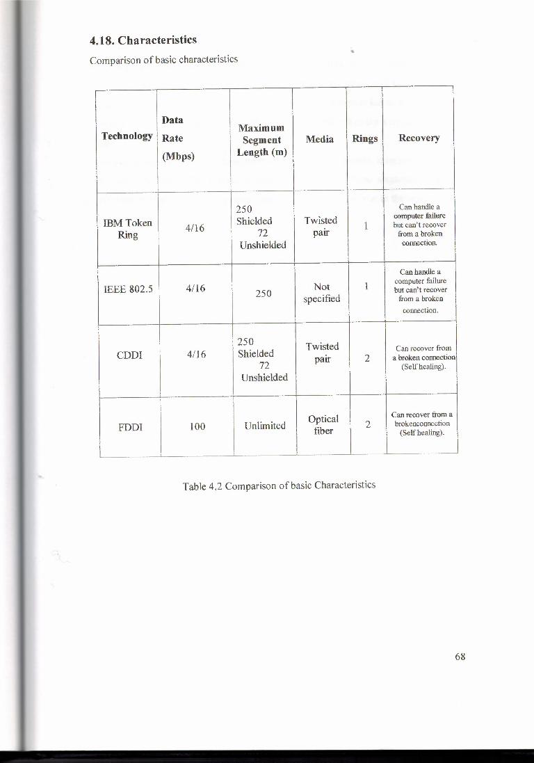
4.18. Characteristics
Comparison of basic characteristics
Data Technology
Maximum Rate Segment Media Rings Recovery
(Mbps) Length (m)
250 Can handle a
IBM Token Shielded Twisted computer failure
Ring 4/16 72 pair 1 but can't recover from a broken
Unshielded connection.
Can handle a
IEEE 802.5 4/16 Not 1 computer failure
250 but can't recover specified from a broken
connection.
250 Twisted CDDI 4/16 Shielded Can recover from
72 pair 2 a broken connection (Self healing).
Unshielded
Optical Can recover from a
FDDI 100 Unlimited 2 brokenconnection fiber {Self healing).
~
Table 4.2 Comparison of basic Characteristics
68

4.19. Summary Token Ring technology was developed in the 1970s by IBM. Token-passing networks
move a small frame, called a token, around the network. Possession of the token grants
the right to transmit. If a node receiving the token has no information to send, it passes
the token to the next end station. Each station can hold the token for a maximum period
of time.
If a station possessing the token does have information to transmit, it seizes the token,
alters 1 bit of the token (which turns the token into a start-of-frame sequence), appends
the information that it wants to transmit, and sends this information to the next station
on the ring.
69

CH. 5 •
5.0. Fiber Distributed Data Interface ( FDDI ) FDDT uses an entirely different approach to transmitting data, which basically involves
sending around a number of tokens, with a station only being allowed to send a frame if
it captures a token. The main advantage of FDDT is a speed of up to 100-Mbps, and a
maximum cable length ofup to ZOO-km.
Figure 5 .1 Shows FDDl network
For long-distance network links, a different type of equipment is frequently used, which
is based on a standard named X.25. Many so-called Public Data Networks, like Tymnet
in the U.S., or Datex-P in Germany, offer this service. X.25 requires special hardware,
namely a Packet Assembler/Disassembler or PAD. X.25 defines a set of networking
protocols of its own right, but is nevertheless frequently used to connect networks
running TCP/TP and other protocols. Since TP packets cannot simply be mapped onto
X.25 (and vice versa), they are simply encapsulated in X.25 packets and sent over the
network. Frequently, radio amateurs use their equipment to network their computers; this is
called packet radio or ham radio. The protocol used by ham radios is called AX.25,
which was derived from X.25. Other techniques involve using slow but cheap serial lines for dial-up access. These
require yet another protocol for transmission of packets, such as SLIP or PPP, which
will be described below.
70

~ Desktop Si,stem \Deskt!)p System
FOOi - all staflnns funclicning
Figure 5.2 a shows Fddi all station working
\
- mr: ~ Desktop System
p .r
-
\ \
Desktop System
FD DI - one Station is down
Figure 5.2 b shows just one FDDI station is down
71

5.1. PERFORMANCE OF FDDI
FOOi is a high-performance fiber optic token ring LAN running at 100 Mbps up to
1000 stations connected. It is used in the industries or factories where high speed and
accuracy needed .It can be used in the same way as any of the 802 LANs, but with its
high bandwidth, another common use is as a backbone to connect copper LANs, as
shown in Fig. 5.3. FOOi-iI is the successor to FOOi, modified to handle synchronous
circuit-switched PCM data for voice or ISDN traffic, in addition to ordinary data. We
will refer to both of them as just FOOi. This section deals with both the physical layer
and the MAC sublayer ofFDDL
Bridge
Ethernet
Token ring
FDDI ring _,J. Bridge
"\ £ b Computer
~1~:.~ ..
Fig. 5.3 An FOOi ring being used as a backbone to connect LANs and computers
FOOi uses multimode fibers because the additional expense of single mode fibers is not
needed for networks running at only 100 Mbps. It also uses LEDs rather than lasers, not
only due to their lower cost, but also because FOOi may sometimes be used to connect
directly to user workstations. There is a danger that curious users may occasionally
unplug the fiber connector and look directly into it to watch the bits go by at 100 Mbps.
With a laser the curious user might end up with a hole in his retina. LEDs are too weak
to do any eye damage but are strong enough to transfer data accurately at 1 00 Mbps.
72

The FOOi design specification calls for no more than 1 error in 2.5 x 1010 bits. Many
implementations do much better. • The FDDI cabling consists of two fiber rings, one transmitting clockwise and the other
transmitting counterclockwise, as illustrated in Fig. 5.2 (a). Tf either one breaks, the
other can be used as a backup. lf both break at the same point, for example, due to a fire
or other accident In the cable duct, the two rings can be joined into a single ring
approximately twice as Jong, as shown in Fig. 5 .2. Each station contains relays that can
be used to join the two rings or bypass the station in the event of station problems. Wire
centers can also be used, as in 802.5.
Fig. 5.4. (a) FOOi consists of two counter rotating rings, (b) In the event of failure of
both rings at one point, the two rings can be joined together to form a single long ring
FDDI defines two classes of stations, A and B. Class A stations connect to both rings.
The cheaper class B stations only connect to one of the rings. Depending on how
important fault tolerance is, an installation can choose class A or class B stations, or
some of each. The physical layer does not use Manchester encoding because 100-Mbps Manchester
encoding requires 200 mega baud, which was deemed too expensive. lnstead a scheme
called 4 out of 5 encoding is used. Each group of 4 MAC symbols (Os, Is, and certain
non-data symbols such as start-of-frame) are encoded as a group of 5 bits on the
medium. Sixteen of the 32 combinations are for data, 3 are for delimiters, 2 are for
control, 3 are for hardware signaling, and 8 are unused. ~ The advantage of this scheme is that it saves bandwidth, but the disadvantage is the loss v-.. of the self-clocking property of Manchester encoding. To compensate for this loss, a
long preamble is used to synchronize the receiver to the sender's clock. Furthermore, all
clocks are required to be stable to at least 0.005 percent. With this stability, frames up to
73

4500 bytes can be sent without danger of the receiver's clock drifting too far out of sync
with the data stream •
The basic FDDI protocols are closely modeled on the 802.5 protocols. To transmit data,
a station must first capture the token. Then it transmits a frame and removes it when it
comes around again. One difference between FDD1 and 802.5 is that in 802.5, a station
may not generate a new token until its frame has gone all the way around and come
back. In FDDI, with potentially 1000 stations and 200 km of fiber, the amount of time
wasted waiting for the frame to circumnavigate the ring could be substantial. For this
reason, it was decided to allow a station to put a new token back onto the ring as soon as
it has finished transmitting its frames. In a large ring, several frames might be on the
ring at the same time.
5.2. Frame Format
FDDI data frames are similar to 802.5 data frames. The FDDI format is shown in Fig.
5.5a The Start delimiter and End delimiter fields mark the frame boundaries. The
Frame control field tells what kind of frame this is (data, control, etc.). The Frame
status byte holds acknowledgement bits, similar to those of 802.5. The other fields are
analogous to 802.5.
2or 6 NO limit 4 1 f Bytes ;,B 2 or6 -- --{r:-T I !] G I Destination Source Checksum oa~ Preamble _ aoorsss address
=!J l L__ Frame cor.lfo\ Ending delimiter ----· Sia\'\ delirni\er Frame status -
Figure 5 .5 a FDD1 frame format
In addition to the regular (asynchronous) frames, FDD1 also permits special
synchronous frames for circuit-switched PCM or lSDN data. The synchronous frames
are generated every 125 micro sec by a master station to provide the 8000 samples/sec
-~ needed by PCM systems. Each of these frames has a header, 16 bytes of noncircuit
switched data, and up to 96 bytes of circuit-switched data (i.e., up to 96 PCM channels
per frame).
74

F iel::I length, in IJ\,'teS 1
4
Destination FCS End
Start At;oees Fr.ame Source aajress Data deli'n itier deimler con1r01 c:ontiol addiess
- -
Token
- Stan At;cess Erd
delmiter control delimilli'r
Figure 5.5b
The number 96 was chosen because it allows four Tl channels ( 4 x 24) at 1.544 Mbps or
three CCITT El channels (3 x 32) at 2.048 Mbps to fit in a frame, thus making it
suitable for use anywhere in the world. One synchronous frame every 125 micro sec
consumes 6.144 Mbps of bandwidth for the 96 circuit-switched channels. A maximum
of 16 synchronous frames every 125 micro sec allows up to 1536 PCM channels and
eats up 98.3 Mbps. Once a station has acquired one or more time slots in a synchronous frame, those slots
are reserved for it until they are explicitly released. The total bandwidth not used by the
synchronous frames is allocated on demand. A bit mask is present in each of these
frames to indicate which slots are available for demand assignment. The non
synchronous traffic is divided into priority classes, with the higher priorities getting first
shot at the leftover bandwidth. The FDDI MAC protocol uses three timers. The token holding timer determines how
long a station may continue to transmit once it has acquired the token. This timer
prevents a station from hogging the ring forever. The token rotation timer is restarted
every time the token is seen. If this timer expires, it means that the token has not been
sighted for too long an interval. Probably it has been lost, so the token recovery
procedure is initiated. Finally, the valid transmission timer is used to time out and
recover from certain transient ring errors. FDDI also has a priority algorithm similar to 802.4. It determines which priority classes
may transmit on a given token pass. If the token is ahead of schedule, all priorities may
transmit, but if it is behind schedule, only highest ones may send.
75

5.2.1 Tokens consist of
Start delimiter - which alerts the stations of a token arrival (or data/command frame).
Access control byte - which contains the priority and reservation fields, a token bit to
differentiate token from data/command frame and a monitor bit checking whether a
frame is circling the ring endlessly.
5.3. FDDI - Self healing
As described above FDDI networks implements a recovery mechanism which enable
the network to function properly even under a broken ring. FOOi uses two rings to
achieve recovery capabilities. As shown a token is passed simultaneously on the
network's inner and outer rings which backup each other. As shown in the following
figure in case of broken connection or station malfunction, the closest station closes
the network loop by sending the token it received from the outer/inner ring back using
the inner/outer ring.
This feature is called Self healing. End delimiter - which signals the end of a frame, end of a logical sequence and
damaged frames. Data/Command Frames carry information for upper-layer protocols.
After the Access control byte a frame control byte arrives and indicates whether it is a
data or control information (and which) frame. Then arrives two address fields (source
& destination) each 6 bytes long. Data follows these fields (its length depends on the
time each station can hold a token) and then a FCS (frame check sequence) field. At the
end as in tokens, an end delimiter completes the frame.
5.4. Physical Layer Components
The FOOi Physical layer is divided into a Physical Layer Protocol (PHY) sublayer and
a Physical Layer Medium Dependent (PMD) sublayer. In FOOi terminology, a station is an addressable network component that is capable I
-~ of generating and receiving frames. Each instance of a PHY sublayer entity and a I PMD
sublayer entity within a station is called a port. A station can implement one or I more
ports. Each port is attached to the transmission medium through a Medium Interface
Connector (MIC).
76

5.5. STATION TYPES AND NETWORK TOPOLOGIES
A station contains one or more MAC sublayer entities, one or more ports, and a single
station management (SMT) entity. There are various ways in which stations and other
devices can be configured to form an FOOi network, and various types of MICs are
defined for attaching a device to the network. We will look next at the station
configurations and MIC types that are defined by the FOOi standard and examine the
various types of network topologies that can be formed using the different station
configurations.
5.6. Single-Attachment Station
A single-attachment station implements a single MIC of type A single-attachment sta
tion is typically connected, via a single transmission medium segment, to a concentrator
implementing a MIC connector of type Figure 5.6 shows the architectural model of a single-attachment station. It contains an
SMT entity, a MAC sublayer entity, and one port having a MIC of type
Station
!MAC I Peril I ISMT
I PHY! !PMo!
Figure 5 .6 shows the single attachment unit
5.7. Station Management Component
A station has a single station management (SMT) component, which is responsible for
monitoring the operation of the station and for controlling the various management-ori
ented attributes of other station components. The SMT component implements the fol-
lowing functions:
77

• Initializing, inserting, and removing stations.
• Managing a station's configuration, its attachment to the FDDI transmission
medium, and its connections with other stations.
• Isolating and recovering from faults
5.8. Dual-Attachment Concentrator
A concentrator is an FDDl device that has more ports than are needed to simply attach
the concentrator itself to the FDDT network. The additional ports can be used to attach
other stations to the network. A dual-attachment concentrator (DAC) is a station that
has three or more ports, each associated with its own MIC. A dual-attachment concentrator is used to create a network topology called a dual
ring of trees, in which tree structures branch off the dual counter-rotating ring to
connect single-attachment stations (SASs). (The architecture of a single-attachment
station is described later in this chapter.) A dual-attachment concentrator implements
one MIC of type A, one of type B, and one or more MICs of type M. Each MIC of type
M (short for master) in a concentrator is attached to a MIC of type S (short for slave),
implemented in a single-attachment station. Notice that the type A and type B MICs are interconnected in exactly the same way
as in the example in Fig. 5.7. A simple concentrator network-made up of dual
attachment stations, dual-attachment concentrators. The numbers next to each station indicate the path the token takes as it travels
from station to station around the primary ring. ln this example, we are assuming that
each concentrator implements a MAC sublayer entity and also acts as a station. When a
concentrator is also a station, it logically follows any slave stations to which it is
attached. An architectural model of the dual-attachment concentrator is shown in Fig.5.5. A
dual-attachment concentrator can implement zero or more MAC entities. If a device
78

Station
I MAC I I MAC I I MAC I SMT
Figure 5.7 shows the dual Attachment unit
Figure 5 .8 shows a simple FDDI network consisting of four dual-attachment stations. The network is formed by connecting the type A MIC of one station to the type B MIC of the next station with a single transmission medium segment. Since each transmission medium segment is full-duplex, transmissions can flow in both directions simultaneously over each segment, thus forming a dual, counter-rotating ring structure.
FDDI MICs and transmission medium segments are designed to facilitate the connection of MICs in the proper manner. For example, the connectors at the end of transmission medium segments do not allow one type A MIC to be attached to another
type A MIC. The FDDI standard does not specify how the primary and secondary rings are to be
used. This is left to the implementers. Normally, the primary ring is used to carry data,
and the secondary ring is idle and is used to recover from physical link and station fail
ures. However, it is possible, although not common, for an FDD1 implementation to
employ both rings simultaneously for data transmission
.~ Prirnarv Ring
/ r -- SeGondary Ring //
OAS, DAS2 DASS DAS4
Figure 5.8 Four Dual attachment station
79

5.9. FDDI ARCHITECTURAL MODEL •
The FOOi specification defines an architectural model describing the organization of
the Data Link and Physical layers. This architectural model is illustrated in Fig. 5.9. The
components in the architectural model can be divided among those components
associated with the Data Link layer, those associated with the Physical layer, and those
associated with the station management (SMT) function.
LLC Sublayer user
i Logical Link Control (LLC) Sublayer
Data link
Layer
l Medium Access Control (MAC) Sublayer
Station
Management ,
(SMT)
i Function Port
Physical layer
Physical Layer Protocol (PHY) Sublayer
Physical Layer Medium Dependent (PMD)
MTC
Medium Interface Connector { rnic)
Full-Duplex Point-to-point Fiber Optic Link
Figure 5.9 shows the architectural model of FDDI
5.10. Ring Monitoring Functions All stations on the ring participate in distributed algorithms that monitor the operation
of the ring to check for invalid conditions that may require the ring to be reinitialized.
An example of an invalid condition is a ring that currently has no token circulating. To
80

detect the absence of a circulating token, each station maintains a token rotation timer
(TRT), which the station resets each time it receives the token. ff the timer expires twice
before the station next receives the token, the station assumes the token has been lost
and begins the ring initialization procedure. Other types of incorrect activity can also cause a station to begin the station initial-
ization procedure. A station begins the ring-initialization process by performing a claim
token procedure.
5.11. Claim Token Procedure
..
ln performing the claim token procedure, a station bids for the right to initialize the ring.
The station begins the claim token procedure by issuing a continuous stream of control
frames, called Claim frames. Each Claim frame contains a suggested Target Token
Rotation Time (TTRT) value. Tf a station sending Claim frames receives a Claim frame
from another station, it compares TTRT values. If the station's own TTRT value is
lower, it keeps transmitting Claim frames. Tfthe TTRT value in a Claim frame a station
receives is lower than its own TTRT value, it passes on the received Claim frame
instead of its own. If the values are the same, MAC addresses are used to determine
which station takes precedence. Eventually, the Claim frame with the lowest TTRT value will be passed on by other
stations and will return to the station that sent it. At this point the source station recog
nizes itself as the winner in the claim token procedure. That station has won the right to
initialize the ring and continues by performing the ring initialization procedure. As a
result of the claim token procedure, all stations now have the TTRT value to be used in
subsequent ring operation because all stations have seen the TTRT value in the Claim
frame sent by the winning station . The claim token procedure sounds complex and time consuming, but with a data rate of
1 OOMbps, the procedure takes only a millisecond or 'two to complete, even on a large
ring.
5.12. Ring Initialization
The station winning the claim token procedure sets its own token rotation timer (TRT)
to the negotiated TTRT and transmits a token onto the ring. Each station that receives
the token then sets its own TTRT to the negotiated value and transmits the token to the
81

next station. No frames are transmitted until the token has passed once all the way
around the ring. The purpose of the initial token rotation is to' align TTRT values and
TRT times in al I stations on the ring.
5.13. Beacon Process
When a serious failure occurs, such as a break in the ring, stations use a beacon process
to locate the failure. Each station's station management (SMT) component can initiate
the beacon process. When a station that has been sending Claim frames recognizes that
a defined time period has elapsed without the claim token process being resolved, it
begins the beacon process by transmitting a continuous stream of Beacon frames. If a
station receives a Beacon frame from another station, it stops sending its own Beacon
frames and passes on the beacon frames it has received. Eventually, Beacon frames
from the station immediately following the break will be propagated to all stations in
the network. Some process external to the MAC sublayer entity must then be invoked to
diagnose the problem and to reconfigure the ring to bypass the failure. Tf during the
beacon process a station receives its own Beacon frames, it assumes the ring has been
restored and initiates the claim token procedure.
5.14. Wideband Channels
When an FOOi II network is operating in basic mode, the entire 100 Mbps transmission
capacity is used for packet-switching services. When the network is operating in hybrid
mode, the transmission capacity is split between a packet-data channel and several
wideband channels (WBCs). Up to 16 wideband channels can be used that each
supports a data rate of 6.144 Mbps. The minimum capacity of the packet-data channel is
.768 Mbps. A total of .928 Mbps of channel capacity is devoted to overhead functions,
making the total capacity of an FDDl TT network operating in hybrid mode 99 .072 Mbps
5.15. FDDI II 'i
At the time of writing, an upwardly compatible extension of FOOi, called FDDl ll, is
undergoing standardization in TSO. The original FDDT specification is now sometimes
called FDDI I. The original intent of FDDI technology was to provide a higher-speed
alternative to other types of LAN technology, such as Ethernet and Token Ring, for data
82

applications. However, since standardization work on FOOi was begun, there has been
an increasing need to use integrated networks that carry both data and non data traffic,
such as voice and video. An FDDT T LAN uses packet-switching technology to carry user data in variable
length frames. As discussed earlier in this chapter FDDI I defines a capacity allocation
scheme, using synchronous frames, that can be used to control the amount of time any
single station has access to the transmission medium. This mechanism can be used to
guarantee a certain minimum sustained data rate to a user, but it does not provide for a
uniform data stream between two communicating stations. Packet-switching
mechanisms are not well suited for communication applications in which a constant,
uniform data stream is required. Circuit-switching technologies are better suited for
such applications.
5.16. Isochronous Transmission
FOOi II defines additional optional protocol mechanisms that allow an FOOi data link
to be used to provide circuit-switched services in addition to packet-switched services.
The mode of transmission that is used to provide circuit-switched services is called
isochronous transmission. The FDDl TI isochronous transmission mechanisms impose a
125-microsecond frame structure on the ring. The frame structure is used to divide the
total transmission capacity into a number of discrete channels by allocating regularly
repeating time slots to users that require them. These discrete channels are used to
provide virtual circuit between pairs of communicating stations.
5.17. Basic and Hybrid Operation
An FOOi II network can operate in either basic or hybrid mode. In basic mode, the net
work functions in an identical fashion to an FDDI I network and provides only packet
switching services. In hybrid mode, the capacity of the transmission medium is split
between packet-switching and circuit switching. Figure 14.19 illustrates the FDDI TI architectural model. A new sublayer structure
imposes a Hybrid Ring Control (HRC) function between the conventional FDDI I
Medium Access Control (MAC) sublayer and the Physical layer. The HRC function
contains a new Isochronous Medium Access Control (IMAC) sublayer and a Hybrid
Multiplexer (HMUX) function. The IMAC sublayer provides services to a circuit-
83
switched multiplexer component that operates at the level of the LLC sublayer. The ..• HMUX function provides an interface between the Physical layer and the two
alternative MAC sublayer functions and divides the transmission capacity into channels
that can be split between packet-switching and circuit-switching applications.
5.18. Optional FDDI MAC Protocol Features
The FDDI standard specifies optional mechanisms that implement a capacity allocation
scheme. This scheme is designed to support a mixture of stream and burst transmission
and transmissions involving dialogs between pairs of stations.
5.18.1. Interconnecting FDDI and Ethernet LANs
The DEC FDDI architecture provides provision for using an FDDI LAN as a back for
individual Ethernet LAN data links. To handle such extended LANs, the LLC sub er in
DEC's FDDI architecture provides for handling mapped Ethernet frames. A ma
Ethernet frame is encapsulated within an IEEE/ISO SNAP PDU, which is, in enclosed
in an FDDI MAC frame for transmission across an FDDI data link. This all frames
originating from FDDI NICs, frames originating from NICs conforming to IEEE/ISO
CSMA/CD standard, and frames originating from NICs conforming to the ernet Version
2 Specification to all coexist in the same network.
5.19. Future Direction
FDDI Il represents a refinement of the shared access technology used in local area
works that allows the LAN to be used for applications that are better suited to c
switching. However, the future direction of networking technology to support both and
non data applications most probably lies in the use of Asynchronous Transfer Mode
(ATM) technology in which any pair of communicating stations is always provided a
high-speed virtual circuit.
84

5.20. SUMMARY
The Fiber Distributed Data Interface (FDDI) standard defines a multi-access form of
link that uses a ring-structured network topology. Stations are connected to one and
using point-to-point fiber-optic cable segments to form a ring, and stations pass frames
one station to the next so that all stations eventually receive all frames that are
transmitted The FDDI service definition defines an MA UNITDAT A unconfirmed data traffic
service and an MA TOKEN token request service. The FDDI protocol specification
defines the format of the MAC-SDU, specifies how the MAC-SDU is encapsulated
MAC-PDU, and documents the procedures controlling the exchange of MAC-N
between communicating stations.
85

Conclusion
Ethernet is supposed to be a single common medium with multiple connections.
The connection between the hub in the wiring closet and the adapter card in the PC
forms a single point- to-point Ethernet segment between two stations. The connection to
the rest of the LAN involves active electronics in the hub. In current use, this is done
with a repeater that copies every bit and propagates collisions.
A new generation of even smarter hubs provides a "bridge" connection between the
main LAN and the phone wire. This has two advantages:
• It provides greater security, because the desktop user cannot spy on traffic
addressed to other nodes. • It provides each desktop user with an isolated, private 10 megabit data path free
of collisions. The connection between hubs can then use a higher speed fiber
optic protocol to deliver much greater performance than simple Ethernet. This
hybrid represents a compromise of high performance and low cost.
However, bridging Ethernet to any other LAN protocol requires some attention to frame
formats. Unfortunately, the "standards" are still a mess. DIX and 802 messages flow on
the same LAN. Bridges must be aware of the protocol conventions and select the correct
"1 frame format when moving data onto or off of an Ethernet.
As you can see, Fast Ethernet can be effectively integrated into a legacy Ethernet
installation, transparently integrated into the infrastructure and combined with switching
technology to enhance performance and improve response times. For best performance,
it is advisable to:
• Micro segment large workgroups, since keeping clients on relatively small
segments increases overall network performance by decreasing traffic.
•
Give each server and power user a dedicated segment, or connect them to small
Fast Ethernet workgroups, to alleviate server bottlenecks and provide sufficient
bandwidth for data-intensive applications. Use switches rather than routers or bridges to interconnect segments, since they
are less expensive and easier to use.
•
With Fast Ethernet, the administrator can retain the basic network layout. The LAN can
continue to be managed and maintained with the same familiar tools used for 10 Mbps
86

Ethernet. And, the price per port for this evolutionary technology that offers as much as ••
a tenfold bandwidth increment will soon approach today's Ethernet pricing.
Token-passing networks move a small frame, called a token, around the network.
Possession of the token grants the right to transmit. If a node receiving the token has no
information to send, it passes the token to the next end station. Each station can hold the
token for a maximum period of time. A station with information to transmit "sizes" the
token, marks it as being in use, and inserts the information. The "busy" token, plus
message, is then passed around the circle, copied at its destination, and eventually
returned to the sender. The sender removes the attached message and then passes the
freed token to the next station in line.
FOOi works on the same principle of token ring but the main difference is that fiber
optic have much greater bandwidth than normal token ring and cabling is consist of two
fiber Rings, one transmitting clockwise and other transmitting counter clockwise. And
is more secure and can work at higher speed even at the longer distance. The FOOi
service definition defines an MA UNITOATA unconfirmed data traffic service and an
MA TOKEN token request service. The FOOi protocol specification defines the format
of the MAC-SOU, specifies how the MAC-SOU is encapsulated MAC-POU, and
documents the procedures controlling the exchange ofMAC-N between communicating
stations. And is used in the industrial scale.
So for industrial use it is the best network topology.
87

References
1) James Martin, Local Area Network 2nd Edition, USA ,1999.
2) Fakhreddin Mamedov,2000,Telecommunication'Nicosia,Near East
University Press.
3) Andrew S. Tanenbaum , Computer Networks , 3rd Edition Prentice - Hall
International UK 1994.
4) Dr. Jerry Fitzgerald ,Business Data Communications 4th Edition, John Willey &
Sons ,INC Canada, 1994.
5) Douglas E. Comer, Computer Networks and lntemets , 2nd Edition, Prentice -
Hall USA 1997.
6) WWW.CISCO.COM
7) WWW.IEEE.COM
8) WWW.METU/EDU/NETWORKING/LECTURENOTES
•..
88