Embed Size (px)
Citation preview
Factory Test Equipment: HID Ballast Investigation Datasheets: A draft version of the datasheets has been attached for your review. Nominal System: It is imperative that the ballast, lamp, and capacitor constitute a nominal system in accordance with Clause 18.3: The load for the leakage current, input, and heating tests is to consist of a lamp(s) of the type for which the ballast is intended to be used. Any lamp ballast and capacitor required are to constitute a nominal system. A nominal system is to be considered to exist, with the system stabilized at rated voltage, when the lamp wattage and voltage are within ±5 percent of the ballast rating in accordance with the ANSI C78 series standards or the manufacturer’s data sheet. Testing: Tests are performed as follows:
• Input Test: Test performed for each input tap rating for each ANSI lamp type specified. Measurements are made using power analyzers (V, A, W, PF) in the input circuit and in the lamp circuit. The meter should be suitable for the peak voltage of the ignitors during starting. Test Voltages shall be available for each rated input condition, in accordance the requirements shown below from UL 1029, Clause Conditions evaluated during the test:
o no lamp o starting o normal operation o shorted lamp
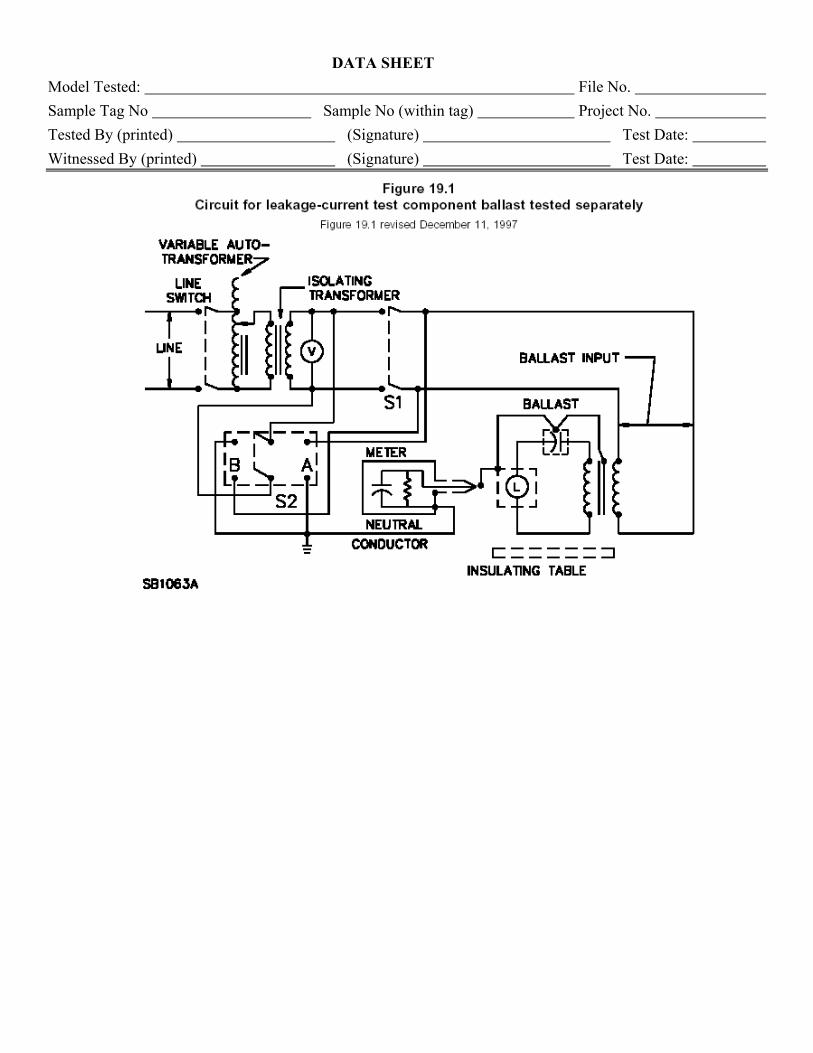
• Leakage Current: Each ballast tested at highest rated input voltage. The test circuit is as
shown below (see datasheets), including the isolation transformer, variac, switching circuit, and meter. The meter is to have the characteristics as described in UL 1029, Clause 19.5.
• Burnout: Each ballast tested, lamp open circuit condition and short circuit condition, at
voltage corresponding to highest input current. Fuses (Class H non-renewable fuses) with appropriate ratings per Clause 24.2, must be used during testing.
• Dielectric Voltage Withstand Test: Each ballast is tested. Test voltage is calculated
using the highest RMS voltage measured on the input or output during the Input Test.
• Temperature: The temperature test is the most time consuming (and most critical) test of the entire test program.
o Temperatures are measured by both thermocouple method and by change-of-resistance method. For the thermocouple (TC) measurements, TC are to be constructed in accordance with Clause 21.1.7. The TC junction is to consist of the wires crossing at a single point and welded. Twisting of the TC wires is not acceptable. Chart recorder or computer data acquisition is required to read the TC temperatures.
o Change-of-Resistance (CofR) measurements are to be made on the primary coil and the secondary coil for each voltage input tap. For example, a four-tap ballast requires eight CofR temperature tests. The following description is of a typical
testing scenario. If you have other equipment or testing methods, please provide details for our evaluation prior to the witness testing trip: Resistance measurements are to be made with a precision 4-wire type
ohmmeter. In order to complete the testing in a reasonable amount of time, we require that at least two ohmmeters to be available such that the primary and secondary winding for each tap can be measured simultaneously.
We recommend at least six (6) test stations prepared so that three ballasts can be tested at the same time. The stations should each have the necessary power available corresponding to the input taps of the ballasts. The stations must be spaced apart (or shielded) such that magnetic fields from one ballast do not interfere with the testing of the adjacent ballast.
The coil under test must be completely isolated from the other components (capacitor, starter, other windings) during the resistance measurements. This is achieved by using various multi-pole knife switches. A picture of a typical knife switch is attached for your reference. A common circuit diagram is also attached (CofR.pdf).
For circuits without a capacitor between the primary and secondary coils, specially prepared samples will be required. These samples are to be constructed with extra lead length (approximately 150 mm) between the primary and secondary windings in order to isolate the coil under test. Please see the attachment for details (CofR.pdf)
Cold (initial) resistance measurements are to made prior to any testing and after the ballasts have acclimated to the testing location for 24 hours.
Test Equipment Calibration: All test equipment must be calibrated annually and traceable to NIST or a nationally recognized certification agency. Laboratory staff knowledgeable in the use and maintenance of the equipment are to be available for testing. Test Voltages: For supply circuit voltages of 120, 220 (European), 277, or 347 volts, the supply circuit had a single side grounded. For supply circuit voltages of 208, 220 or 240 (North America), or 480 a balanced supply circuit had balanced voltage to ground. Ignitor Testing: Datasheets for the ignitor testing have been included below. Test equipment needed is similar to ballast testing, except an oscilloscope is also needed to capture the starting peak voltage.
• For the temperature test, thermocouples are to be attached to various places on the PWB prior to potting.
• For the component fault test, shorting leads (or opening) leads are to be added to the circuit prior to potting.
DATA SHEET
Model Tested: File No. Sample Tag No Sample No (within tag) Project No. Tested By (printed) (Signature) Test Date: Witnessed By (printed) (Signature) Test Date:
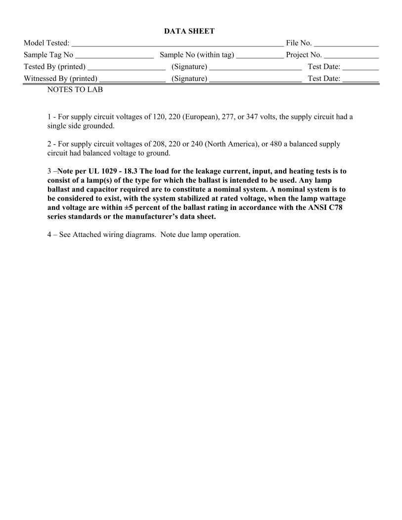
NOTES TO LAB 1 - For supply circuit voltages of 120, 220 (European), 277, or 347 volts, the supply circuit had a single side grounded. 2 - For supply circuit voltages of 208, 220 or 240 (North America), or 480 a balanced supply circuit had balanced voltage to ground. 3 –Note per UL 1029 - 18.3 The load for the leakage current, input, and heating tests is to consist of a lamp(s) of the type for which the ballast is intended to be used. Any lamp ballast and capacitor required are to constitute a nominal system. A nominal system is to be considered to exist, with the system stabilized at rated voltage, when the lamp wattage and voltage are within ±5 percent of the ballast rating in accordance with the ANSI C78 series standards or the manufacturer’s data sheet. 4 – See Attached wiring diagrams. Note due lamp operation.
DATA SHEET
Model Tested: File No. Sample Tag No Sample No (within tag) Project No. Tested By (printed) (Signature) Test Date: Witnessed By (printed) (Signature) Test Date:
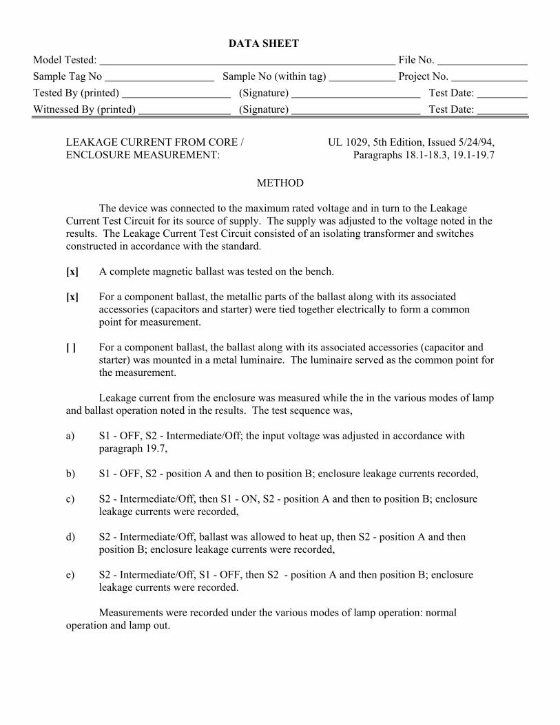
LEAKAGE CURRENT FROM CORE / ENCLOSURE MEASUREMENT:
UL 1029, 5th Edition, Issued 5/24/94, Paragraphs 18.1-18.3, 19.1-19.7
METHOD
The device was connected to the maximum rated voltage and in turn to the Leakage Current Test Circuit for its source of supply. The supply was adjusted to the voltage noted in the results. The Leakage Current Test Circuit consisted of an isolating transformer and switches constructed in accordance with the standard. [x] A complete magnetic ballast was tested on the bench. [x] For a component ballast, the metallic parts of the ballast along with its associated
accessories (capacitors and starter) were tied together electrically to form a common point for measurement.
[ ] For a component ballast, the ballast along with its associated accessories (capacitor and
starter) was mounted in a metal luminaire. The luminaire served as the common point for the measurement.
Leakage current from the enclosure was measured while the in the various modes of lamp and ballast operation noted in the results. The test sequence was, a) S1 - OFF, S2 - Intermediate/Off; the input voltage was adjusted in accordance with
paragraph 19.7, b) S1 - OFF, S2 - position A and then to position B; enclosure leakage currents recorded, c) S2 - Intermediate/Off, then S1 - ON, S2 - position A and then to position B; enclosure
leakage currents were recorded, d) S2 - Intermediate/Off, ballast was allowed to heat up, then S2 - position A and then
position B; enclosure leakage currents were recorded, e) S2 - Intermediate/Off, S1 - OFF, then S2 - position A and then position B; enclosure
leakage currents were recorded. Measurements were recorded under the various modes of lamp operation: normal operation and lamp out.
DATA SHEET
Model Tested: File No. Sample Tag No Sample No (within tag) Project No. Tested By (printed) (Signature) Test Date: Witnessed By (printed) (Signature) Test Date:
DATA SHEET
Model Tested: File No. Sample Tag No Sample No (within tag) Project No. Tested By (printed) (Signature) Test Date: Witnessed By (printed) (Signature) Test Date:
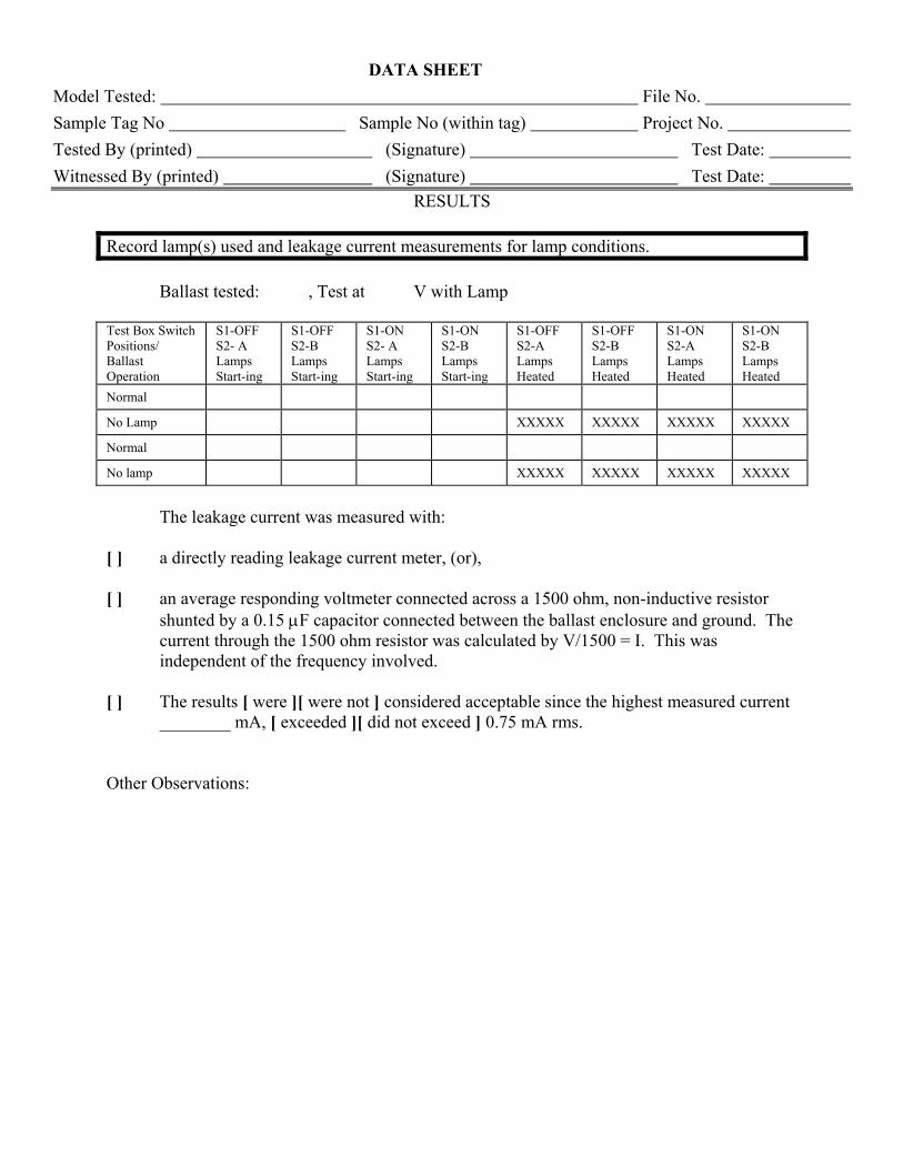
RESULTS Record lamp(s) used and leakage current measurements for lamp conditions. Ballast tested: , Test at V with Lamp Test Box Switch Positions/ Ballast Operation
S1-OFF S2- A Lamps Start-ing
S1-OFF S2-B Lamps Start-ing
S1-ON S2- A Lamps Start-ing
S1-ON S2-B Lamps Start-ing
S1-OFF S2-A Lamps Heated
S1-OFF S2-B Lamps Heated
S1-ON S2-A Lamps Heated
S1-ON S2-B Lamps Heated
Normal
No Lamp XXXXX XXXXX XXXXX XXXXX
Normal
No lamp XXXXX XXXXX XXXXX XXXXX
The leakage current was measured with: [ ] a directly reading leakage current meter, (or), [ ] an average responding voltmeter connected across a 1500 ohm, non-inductive resistor
shunted by a 0.15 µF capacitor connected between the ballast enclosure and ground. The current through the 1500 ohm resistor was calculated by V/1500 = I. This was independent of the frequency involved.
[ ] The results [ were ][ were not ] considered acceptable since the highest measured current
________ mA, [ exceeded ][ did not exceed ] 0.75 mA rms. Other Observations:
DATA SHEET
Model Tested: File No. Sample Tag No Sample No (within tag) Project No. Tested By (printed) (Signature) Test Date: Witnessed By (printed) (Signature) Test Date:
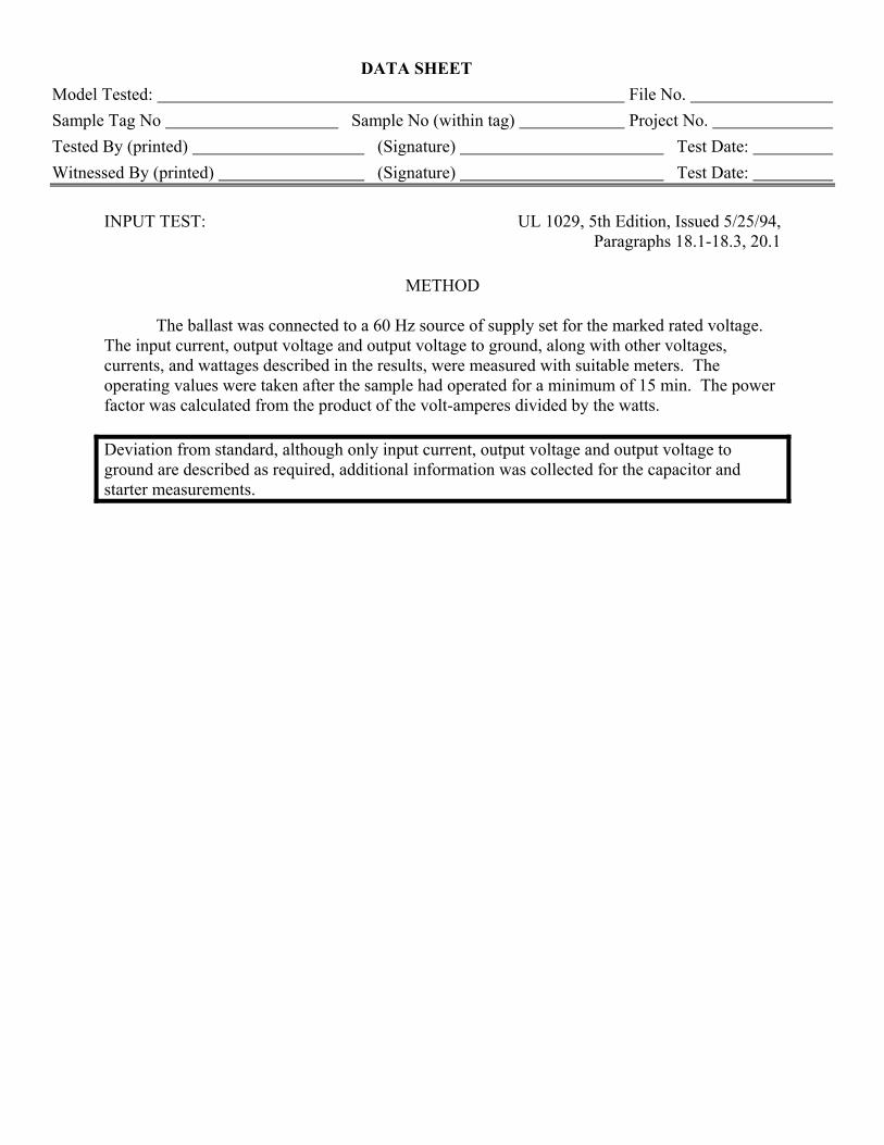
INPUT TEST: UL 1029, 5th Edition, Issued 5/25/94,
Paragraphs 18.1-18.3, 20.1
METHOD The ballast was connected to a 60 Hz source of supply set for the marked rated voltage. The input current, output voltage and output voltage to ground, along with other voltages, currents, and wattages described in the results, were measured with suitable meters. The operating values were taken after the sample had operated for a minimum of 15 min. The power factor was calculated from the product of the volt-amperes divided by the watts. Deviation from standard, although only input current, output voltage and output voltage to ground are described as required, additional information was collected for the capacitor and starter measurements.
DATA SHEET
Model Tested: File No. Sample Tag No Sample No (within tag) Project No. Tested By (printed) (Signature) Test Date: Witnessed By (printed) (Signature) Test Date:
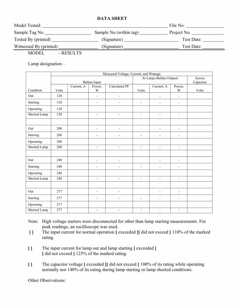
MODEL - RESULTS Lamp designation –
Measured Voltage, Current, and Wattage
Ballast Input At Lamp (Ballast Output) Across
Capacitor
Condition Volts Current, A Power,
W Calculated PF
Volts Current, A Power,
W Volts Out 120 - - - -
Starting 120 - - - - -
Operating 120 Shorted Lamp 120 - - - - -
Out 208 - - - -
Starting 208 - - - - -
Operating 208 Shorted Lamp 208 - - - - -
Out 240 - - - -
Starting 240 - - - - -
Operating 240 Shorted Lamp 240 - - - - -
Out 277 - - - -
Starting 277 - - - - -
Operating 277 Shorted Lamp 277 - - - - -
Note: High voltage starters were disconnected for other than lamp starting measurements. For
peak readings, an oscilloscope was used. [ ] The input current for normal operation [ exceeded ][ did not exceed ] 110% of the marked
rating. [ ] The input current for lamp out and lamp starting [ exceeded ]
[ did not exceed ] 125% of the marked rating. [ ] The capacitor voltage [ exceeded ][ did not exceed ] 100% of its rating while operating
normally nor 140% of its rating during lamp starting or lamp shorted conditions. Other Observations:
DATA SHEET
Model Tested: File No. Sample Tag No Sample No (within tag) Project No. Tested By (printed) (Signature) Test Date: Witnessed By (printed) (Signature) Test Date:
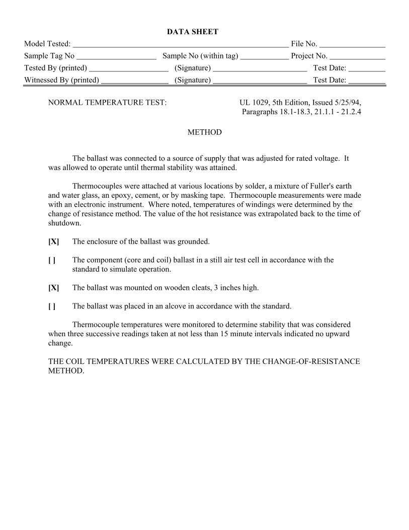
NORMAL TEMPERATURE TEST: UL 1029, 5th Edition, Issued 5/25/94,
Paragraphs 18.1-18.3, 21.1.1 - 21.2.4
METHOD The ballast was connected to a source of supply that was adjusted for rated voltage. It was allowed to operate until thermal stability was attained. Thermocouples were attached at various locations by solder, a mixture of Fuller's earth and water glass, an epoxy, cement, or by masking tape. Thermocouple measurements were made with an electronic instrument. Where noted, temperatures of windings were determined by the change of resistance method. The value of the hot resistance was extrapolated back to the time of shutdown. [X] The enclosure of the ballast was grounded. [ ] The component (core and coil) ballast in a still air test cell in accordance with the
standard to simulate operation. [X] The ballast was mounted on wooden cleats, 3 inches high. [ ] The ballast was placed in an alcove in accordance with the standard. Thermocouple temperatures were monitored to determine stability that was considered when three successive readings taken at not less than 15 minute intervals indicated no upward change. THE COIL TEMPERATURES WERE CALCULATED BY THE CHANGE-OF-RESISTANCE METHOD.
DATA SHEET
Model Tested: File No. Sample Tag No Sample No (within tag) Project No. Tested By (printed) (Signature) Test Date: Witnessed By (printed) (Signature) Test Date:
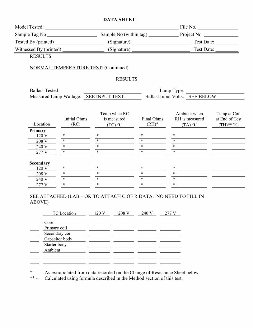
RESULTS NORMAL TEMPERATURE TEST: (Continued)
RESULTS Ballast Tested: Lamp Type: Measured Lamp Wattage: SEE INPUT TEST Ballast Input Volts: SEE BELOW
Initial Ohms
Temp when RC is measured
Final Ohms
Ambient when RH is measured
Temp at Coil at End of Test
Location (RC) (TC) °C (RH)* (TA) °C (TH)** °C Primary
120 V * * * * 208 V * * * * 240 V * * * * 277 V * * * *
Secondary
120 V * * * * 208 V * * * * 240 V * * * * 277 V * * * *
SEE ATTACHED (LAB – OK TO ATTACH C OF R DATA. NO NEED TO FILL IN ABOVE)
TC Location 120 V 208 V 240 V 277 V Core Primary coil Secondary coil Capacitor body Starter body Ambient
* - As extrapolated from data recorded on the Change of Resistance Sheet below. ** - Calculated using formula described in the Method section of this test.
DATA SHEET
Model Tested: File No. Sample Tag No Sample No (within tag) Project No. Tested By (printed) (Signature) Test Date: Witnessed By (printed) (Signature) Test Date:
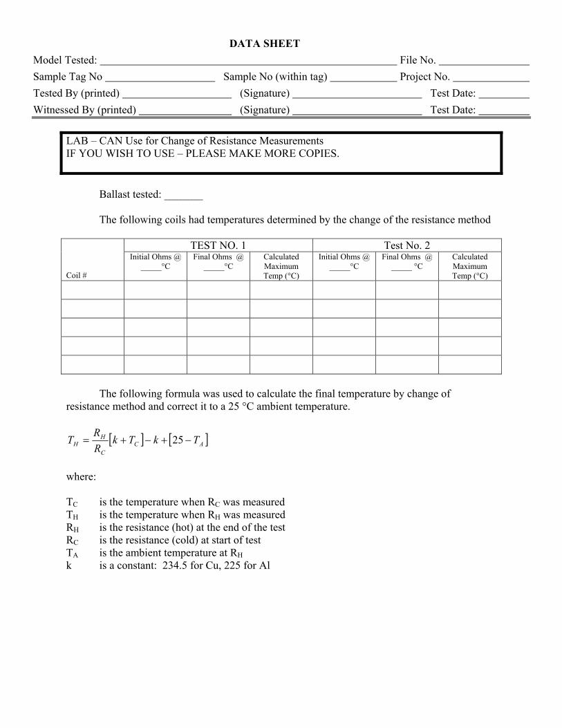
LAB – CAN Use for Change of Resistance Measurements IF YOU WISH TO USE – PLEASE MAKE MORE COPIES. Ballast tested: _______ The following coils had temperatures determined by the change of the resistance method
TEST NO. 1 Test No. 2
Coil #
Initial Ohms @ _____°C
Final Ohms @ _____°C
Calculated Maximum Temp (°C)
Initial Ohms @ _____°C
Final Ohms @ _____ °C
Calculated Maximum Temp (°C)
The following formula was used to calculate the final temperature by change of resistance method and correct it to a 25 °C ambient temperature.
[ ] [ ACC
HH TkTk
RRT −+−+= 25 ]
where: TC is the temperature when RC was measured TH is the temperature when RH was measured RH is the resistance (hot) at the end of the test RC is the resistance (cold) at start of test TA is the ambient temperature at RH k is a constant: 234.5 for Cu, 225 for Al
DATA SHEET
Model Tested: File No. Sample Tag No Sample No (within tag) Project No. Tested By (printed) (Signature) Test Date: Witnessed By (printed) (Signature) Test Date:
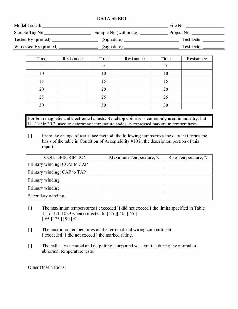
Time Resistance Time Resistance Time Resistance
5 5 5
10 10 10
15 15 15
20 20 20
25 25 25
30 30 30 For both magnetic and electronic ballasts. Benchtop coil rise is commonly used in industry, but UL Table 30.2, used to determine temperature codes, is expressed maximum temperatures. [ ] From the change of resistance method, the following summarizes the data that forms the
basis of the table in Condition of Acceptability #10 in the description portion of this report.
COIL DESCRIPTION Maximum Temperature, ºC Rise Temperature, ºC
Primary winding: COM to CAP
Primary winding: CAP to TAP
Primary winding
Primary winding
Secondary winding
[ ] The maximum temperatures [ exceeded ][ did not exceed ] the limits specified in Table
1.1 of UL 1029 when corrected to [ 25 ][ 40 ][ 55 ] [ 65 ][ 75 ][ 90 ]°C.
[ ] The maximum temperatures on the terminal and wiring compartment
[ exceeded ][ did not exceed ] the marked rating. [ ] The ballast was potted and no potting compound was emitted during the normal or
abnormal temperature tests. Other Observations:
DATA SHEET
Model Tested: File No. Sample Tag No Sample No (within tag) Project No. Tested By (printed) (Signature) Test Date: Witnessed By (printed) (Signature) Test Date:
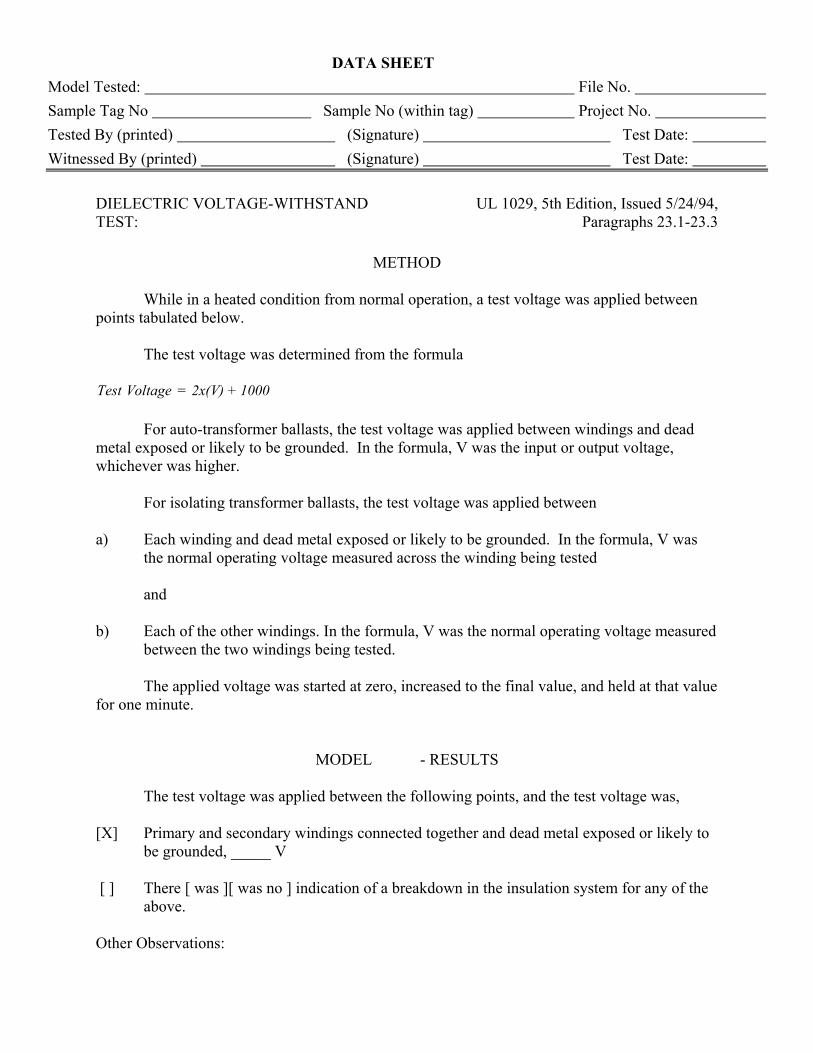
DIELECTRIC VOLTAGE-WITHSTAND TEST:
UL 1029, 5th Edition, Issued 5/24/94, Paragraphs 23.1-23.3
METHOD
While in a heated condition from normal operation, a test voltage was applied between points tabulated below. The test voltage was determined from the formula
1000+2x(V)=VoltageTest For auto-transformer ballasts, the test voltage was applied between windings and dead metal exposed or likely to be grounded. In the formula, V was the input or output voltage, whichever was higher. For isolating transformer ballasts, the test voltage was applied between a) Each winding and dead metal exposed or likely to be grounded. In the formula, V was
the normal operating voltage measured across the winding being tested and b) Each of the other windings. In the formula, V was the normal operating voltage measured
between the two windings being tested. The applied voltage was started at zero, increased to the final value, and held at that value for one minute.
MODEL - RESULTS The test voltage was applied between the following points, and the test voltage was, [X] Primary and secondary windings connected together and dead metal exposed or likely to
be grounded, _____ V [ ] There [ was ][ was no ] indication of a breakdown in the insulation system for any of the
above. Other Observations:
DATA SHEET
Model Tested: File No. Sample Tag No Sample No (within tag) Project No. Tested By (printed) (Signature) Test Date: Witnessed By (printed) (Signature) Test Date:
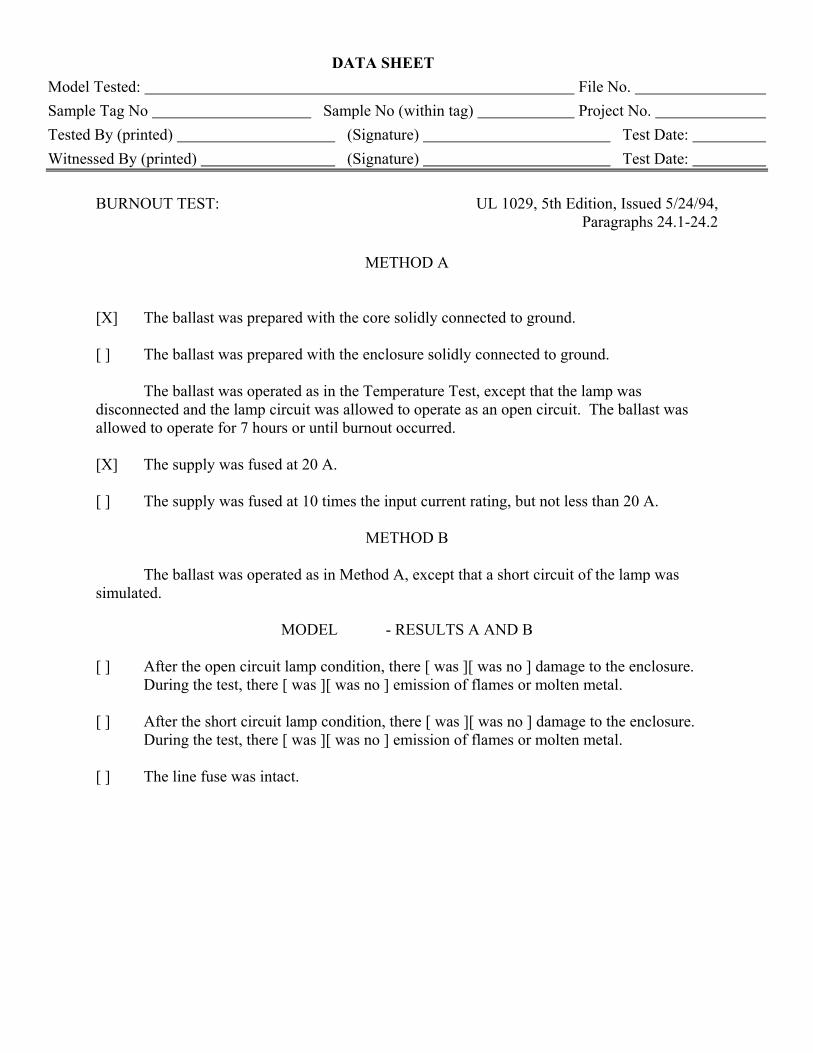
BURNOUT TEST: UL 1029, 5th Edition, Issued 5/24/94,
Paragraphs 24.1-24.2
METHOD A [X] The ballast was prepared with the core solidly connected to ground. [ ] The ballast was prepared with the enclosure solidly connected to ground. The ballast was operated as in the Temperature Test, except that the lamp was disconnected and the lamp circuit was allowed to operate as an open circuit. The ballast was allowed to operate for 7 hours or until burnout occurred. [X] The supply was fused at 20 A. [ ] The supply was fused at 10 times the input current rating, but not less than 20 A.
METHOD B The ballast was operated as in Method A, except that a short circuit of the lamp was simulated.
MODEL - RESULTS A AND B [ ] After the open circuit lamp condition, there [ was ][ was no ] damage to the enclosure.
During the test, there [ was ][ was no ] emission of flames or molten metal. [ ] After the short circuit lamp condition, there [ was ][ was no ] damage to the enclosure.
During the test, there [ was ][ was no ] emission of flames or molten metal. [ ] The line fuse was intact.
DATA SHEET
Model Tested: File No. Sample Tag No Sample No (within tag) Project No. Tested By (printed) (Signature) Test Date: Witnessed By (printed) (Signature) Test Date:
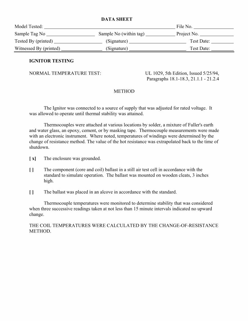
IGNITOR TESTING NORMAL TEMPERATURE TEST: UL 1029, 5th Edition, Issued 5/25/94,
Paragraphs 18.1-18.3, 21.1.1 - 21.2.4
METHOD The Ignitor was connected to a source of supply that was adjusted for rated voltage. It was allowed to operate until thermal stability was attained. Thermocouples were attached at various locations by solder, a mixture of Fuller's earth and water glass, an epoxy, cement, or by masking tape. Thermocouple measurements were made with an electronic instrument. Where noted, temperatures of windings were determined by the change of resistance method. The value of the hot resistance was extrapolated back to the time of shutdown. [ x] The enclosure was grounded. [ ] The component (core and coil) ballast in a still air test cell in accordance with the
standard to simulate operation. The ballast was mounted on wooden cleats, 3 inches high.
[ ] The ballast was placed in an alcove in accordance with the standard. Thermocouple temperatures were monitored to determine stability that was considered when three successive readings taken at not less than 15 minute intervals indicated no upward change. THE COIL TEMPERATURES WERE CALCULATED BY THE CHANGE-OF-RESISTANCE METHOD.
DATA SHEET
Model Tested: File No. Sample Tag No Sample No (within tag) Project No. Tested By (printed) (Signature) Test Date: Witnessed By (printed) (Signature) Test Date:
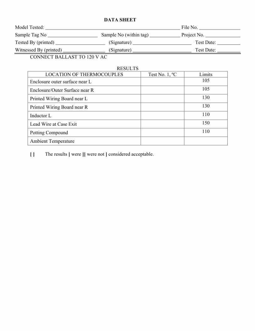
CONNECT BALLAST TO 120 V AC
RESULTS LOCATION OF THERMOCOUPLES Test No. 1, ºC Limits
Enclosure outer surface near L 105
Enclosure/Outer Surface near R 105
Printed Wiring Board near L 130
Printed Wiring Board near R 130
Inductor L 110
Lead Wire at Case Exit 150
Potting Compound 110
Ambient Temperature
[ ] The results [ were ][ were not ] considered acceptable.
DATA SHEET
Model Tested: File No. Sample Tag No Sample No (within tag) Project No. Tested By (printed) (Signature) Test Date: Witnessed By (printed) (Signature) Test Date:
DIELECTRIC VOLTAGE-WITHSTAND TEST:
UL 1029, 5th Edition, Issued 5/24/94, Paragraphs 23.1-23.3
METHOD
Ignitor tested: While in a heated condition from normal operation, a test voltage was applied between points tabulated below. The AC test voltage was determined from the formula Test Voltage = 1750 + 1.25 X V For auto-transformer ballasts, the test voltage was applied between windings and dead metal exposed or likely to be grounded. In the formula, V was the input or output voltage, whichever was higher. For isolating transformer ballasts, the test voltage was applied between a) Each winding and dead metal exposed or likely to be grounded. In the formula, V was
the normal operating voltage measured across the winding being tested and b) Each of the other windings. In the formula, V was the normal operating voltage measured
between the two windings being tested. The applied voltage was started at zero, increased to the final value, and held at that value for one minute.
DATA SHEET
Model Tested: File No. Sample Tag No Sample No (within tag) Project No. Tested By (printed) (Signature) Test Date: Witnessed By (printed) (Signature) Test Date:
RESULTS
The test voltage was applied between the following points, and the test voltage was, [x ] Primary and secondary windings connected together and dead metal exposed or likely to
be grounded, _____ V [ x] There [ was ][ was no ] indication of a breakdown in the insulation system for any of the
above.
DATA SHEET
Model Tested: File No. Sample Tag No Sample No (within tag) Project No. Tested By (printed) (Signature) Test Date: Witnessed By (printed) (Signature) Test Date:
HID STARTER OUTPUT TEST: UL 1029, 5th Edition,
Issued: 5/26/94 Note: These tests are in addition to what is described in UL 1029.
METHOD Model [ x] The starter was connected to an appropriate ballast, Cat. No. manufactured by
. [ x] The lamp wattage was W ( ) and line voltage was V. The lamp was removed and the output observed with an oscilloscope. The following results were noted.
RESULTS Output voltage of ______ V peak was measured. [x ] The results [ were ][ were not ] considered acceptable.
DATA SHEET
Model Tested: File No. Sample Tag No Sample No (within tag) Project No. Tested By (printed) (Signature) Test Date: Witnessed By (printed) (Signature) Test Date:
HID STARTER NORMAL AND ABNORMAL TEMPERATURE TEST:
UL 1029, 5th Edition, Issued 5/26/94
Note: These tests are in addition to what is described in UL 1029.
METHOD A [x] The starter was connected to an appropriate ballast. The starter and ballast were connected for normal operation. The ballast was allowed to operate normally until thermal equilibrium was reached. The temperatures noted in the results were measured. [x] The lamp wattage and supply line voltage were also recorded.
METHOD B The lamp was removed (lamp open circuit). The ballast was allowed to operate until thermal equilibrium was reached. The temperatures noted in the results were measured. [x] The output (starter) voltage was observed with an oscilloscope.
METHOD C The lamp was removed and the lamp lead wires were shorted together. The ballast was allowed to operate until thermal equilibrium was reached. The temperatures noted in the results were measured.
DATA SHEET
Model Tested: File No. Sample Tag No Sample No (within tag) Project No. Tested By (printed) (Signature) Test Date: Witnessed By (printed) (Signature) Test Date:
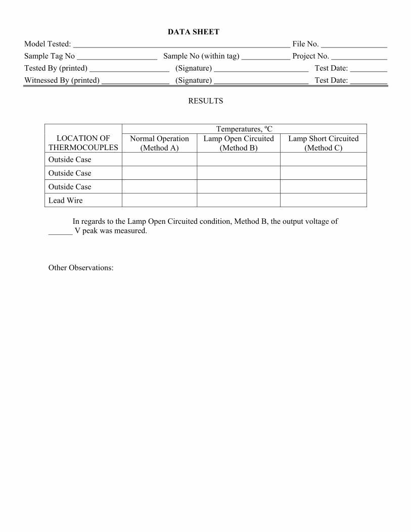
RESULTS
Temperatures, ºC LOCATION OF
THERMOCOUPLES Normal Operation
(Method A) Lamp Open Circuited
(Method B) Lamp Short Circuited
(Method C) Outside Case
Outside Case
Outside Case
Lead Wire
In regards to the Lamp Open Circuited condition, Method B, the output voltage of ______ V peak was measured. Other Observations:
DATA SHEET
Model Tested: File No. Sample Tag No Sample No (within tag) Project No. Tested By (printed) (Signature) Test Date: Witnessed By (printed) (Signature) Test Date:
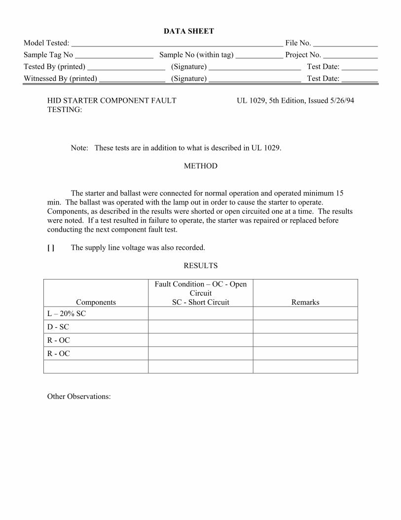
HID STARTER COMPONENT FAULT TESTING:
UL 1029, 5th Edition, Issued 5/26/94
Note: These tests are in addition to what is described in UL 1029.
METHOD The starter and ballast were connected for normal operation and operated minimum 15 min. The ballast was operated with the lamp out in order to cause the starter to operate. Components, as described in the results were shorted or open circuited one at a time. The results were noted. If a test resulted in failure to operate, the starter was repaired or replaced before conducting the next component fault test. [ ] The supply line voltage was also recorded.
RESULTS
Components
Fault Condition – OC - Open Circuit
SC - Short Circuit Remarks L – 20% SC
D - SC
R - OC
R - OC
Other Observations: