Embed Size (px)
Citation preview

Environmental Engineering and Management Journal December 2014, Vol.13, No. 12, 2917-2928
http://omicron.ch.tuiasi.ro/EEMJ/
“Gheorghe Asachi” Technical University of Iasi, Romania
FACTORS INFLUENCING THE SAFETY OF CO2 GEOLOGICAL
STORAGE IN DEEP SALINE AQUIFERS
Xiaojuan Qiao1, Guomin Li2
1Key Laboratory of Computational Geodynamics, Chinese Academy of Sciences,Beijing, China, 100049 2Key Laboratory of Engineering Geomechanics, Institute of Geology and Geophysics, Chinese Academy of Sciences,
Beijing, China, 100029
Abstract Carbon capture and storage is one of the critical technologies that can enable the reduction of carbon dioxide (CO2) emissions of large industrial sites worldwide. The injection of CO2 into saline water formations is related with many factors and processes that control the safety of its long-term storage. This paper analyzes the leakage risks and the factors that influence the integrity of the cap rock in deep saline aquifer formation. Several pathways have leakage potential risks due to deficiencies in the cap rock, new facture networks, abandoned wells, and earthquake-induced fractures. The internal factors that influence the integrity of the cap rock include the type of cap rock and the natural parameters of aquifer formations, such as the permeability, porosity, facture aperture, and so on. External factors, including the multi-process coupling of hydraulic, thermal, chemical, and mechanical processes, are crucial to the stability of the cap rock. Key words: cap rock integrity, coupling multi-process, geological storage safety, permeability, pressure, temperature Received: January, 2011; Revised final: June, 2012; Accepted: July, 2012
Author to whom all correspondence should be addressed: e-mail: [email protected]; Phone: +86 010 82998620
1. Introduction With the increased atmospheric concentration
of carbon dioxide (CO2), storage strategies for CO2
emissions need to be developed. The disposal of carbon dioxide into geological reservoirs offers perhaps the most immediate method for ameliorating anthropogenic CO2 emissions (Herzog, 1999). CO2 capture and its geological storage are now widely acknowledged as major instruments for reducing the emission of greenhouse gases (IPCC, 2007).
CO2 geological storage is a technology that captures CO2 and then places it in a location where it cannot be in contact with the atmosphere for thousands of years. The process of carbon sequestration involves injecting CO2 into deep natural geological formations, including deep saline aquifers, coal beds, depleted oil/gas reservoirs, or deep
unminable coal seams, as shown in Fig. 1. Compared with other kinds of geological
media, deep saline aquifers have great advantages. They have the largest storage capacity volumetrically and are widely distributed; they are also generally located close to CO2 production areas, which allow their immediate access.
Therefore, the retention of CO2 as an immobile phase trapped in the pore space of deep saline aquifers was also identified as an important CO2 storage mechanism.
The storage of CO2 in deep saline aquifers has been proposed as a method of reducing the atmospheric emission of CO2, thereby mitigating global climate change (Bachu, 2000; Bachu and Adams, 2003; Bruant et al., 2002; Holloway, 2001; Koide et al., 1992; Pruess and Garcia, 2002; White et al., 2003).

Qiao and Li/Environmental Engineering and Management Journal 13 (2014), 12, 2917-2928
2918
Fig. 1. Schematic of the carbon capture and storage infrastructure and its relationship with the geological
structure 2. Potential risk analysis
The injection of CO2 requires the
displacement or compression of the existing fluid in a formation. Thus, storage aquifers need to be more than 800 m below the surface to produce the required confining pressures. When CO2 is placed into deep saline aquifers under moderate pressure (73.7 bar or greater) and warmed (to greater than 31.1 °C), it reaches a supercritical state, which has a gas viscosity but retains the same density as the liquid state (Bachu and Adams, 2003; Bentham, 2005). Various reasons ensure the long term security of CO2 storage in properly selected sites. However, the massive and continuous injection of supercritical CO2 into a saturated porous medium involves water displacement and evaporation; mobile water is removed by the injected CO2 according to a two-phase system (brine-CO2). Therefore, the behavior of CO2 and brine water in deep saline aquifers as well as the response of the storage media and the cap rock may compromise the cap-rock integrity and the security of CO2 storage.
Thus, the entire process can be understood as a risk. For example, the injection flow rate is a factor that influences the safekeeping of CO2. Okwen (2010) analyzed the storage efficiency in a case of the constant-rate injection of CO2 into a confined, homogeneous, and isotropic saline aquifer. Rohmer (2010) used an analytical model for the quick assessment of the maximal sustainable overpressure combined with a simplified model in a computationally intensive uncertainty analysis of the framework in the Paris Basin.
The capillary properties of the cap rock also influence the desiccation mechanisms. The buoyancy forces drive the supercritical CO2 upward in the aquifer until it reaches a geological seal. The risk here is the leakage of the injected CO2 or displaced brine from the injection formation into other parts of the subsurface or surface environments. This phenomenon is mainly discussed in this paper as the event that can compromise the safety of CO2
geological storage.
The possibility of CO2 leakage maybe increased because of the following natural or anthropogenic reasons.
2.1. Leakage due to the sealing deficiency of the cap rock
Supercritical CO2 is more buoyant than water. CO2 can migrate out of the storage formation if the cap rock contains a permeable pathway and if the buoyancy pressure is sufficient to exceed the capillary entry pressure for the said pathway. Therefore, a thick seal is essential for all storage scenarios to prevent leakage to overlying formations. The complexity of the geological, chemical, and mechanical conditions of the cap rock can generally cause the cap rock to be discontinuous and heterogeneous or to contain imperfections such as faults or fractures. Although it is difficult to completely seal up such formations for CO2
safekeeping, the performance of this type of sequestration depends strongly on the integrity of the seal over a very long period of time.
The geomechanical cap rock integrity has been studied through a semi-analytical model, and a linear formula has been deduced after a limited number of numerical simulations. This formula is then used to identify the most sensitive parameters in the computation of the effective stress. Abacuses are then established to determine the maximum sustainable pressure depending on the values of these sensitive properties. The majority of the geomechanical work on cap rock integrity has focused on seal failure, most of which have coupled flow-geomechanical simulations of the injection region to assess if the stress changes caused by injection are large enough to cause shear or tensile failure (Rutqvist, 2002; Rutqvist et al., 2007, 2008). In rock media, the hydromechanical effects during CO2 injection were illustrated through the fault stability.
The fault stability analysis, which includes the shear failure as well as the fault-slip and migration along subvertical faults or fracture zones, was studied by many researchers (Chiaramonte et al., 2007; Hillis, 2003, 2004; Pruess and Garcia, 2002; Rutqvist, 2002, 2005, 2007, 2008; Streit). The mechanical process involves thermal stress and heat transportation under high temperatures. The heat transfer behavior and chemical effects have also been analyzed by some researchers (Pruess, 2008; Watson et al., 2005).
A number of numerical codes have been developed to solve the problem of coupling the thermo-hydro-mechanical and chemical effects. Rutqvist and Tsang (2002, 2005) used the TOUGH-FLAC simulator to study the CO2 migration in single-cap rock and multilayer systems. Hassanzadeh (2005) developed a new two-dimensional numerical model of the diffusive and convective mixing in geological CO2 storage by solving the convection-diffusion equation while considering the CO2-brine interface as

Factors influencing the safety of CO2 geological storage in deep saline aquifers
2919
a boundary condition. Bielinski (2008) reported the possibility of using the temperature signals induced by carbon dioxide to monitor the CO2 plume propagation in a formation through a numerical multi-phase simulation program to investigate the non-isothermal effects during CO2 injection.
2.2. Leakage via new facture networks
The combined buoyancy of the CO2 plume and volumetric dilatational strain of the rock exerted on the cap rock layer of the reservoir, when accompanied by the transmission activity between the stress and strain, leads to the deformation and uplift of the overlay layer (Rutqvist et al., 2002; Vasco el al., 2008a, 2008b). To date, carbon dioxide risk assessments tend to use risk scenarios. The major scenarios are related to wellbores, large faults, and unspecified leaking cap rock. Those related to the cap rock either ignore the fracture networks (Chadwick et al., 2007; Lindeberg, 1997; Wildenborg, 2001) or do not explicitly consider them in detail (Grimstad et al., 2009; Kreft et al., 2007; Preston et al., 2005;).
If a cap rock contains a network of fractures, the actual mechanical stress and deformation in and around the injection formation changes the fracture aperture, thereby creating new fractures or reactivating old ones; thus, a permeable pathway can be created by a connecting cluster of open fractures within the network, which may threaten the hydraulic integrity of hydrocarbon reservoirs and CO2 storage projects (Smith, 2011). 2.3. Leakage via an abandoned well
Human activities, such as coal mining, oil
exploration, groundwater drawing, and certain engineering projects, may generate many waste disposal wells that can supply potential leakage pathways because of the mechanical defects developed during well drilling, the completion and/or abandonment of the activity, or the chemical degradation of the well cement and/or casing.
In terms of the risk scenarios, analytical models have been developed for characterizing CO2 leakage through a well. Celia (2011) used analytical solutions for the overall analysis of the CO2 plume and the pressure evolution with leakage along wells in multi-layer, multi-well problems. Nogues (2012) focused on the assignment of effective well permeability values and used a Monte Carlo approach based on thousands of iterations to determine the maximum leakage rates with 95% confidence. Okwen (2011) used the TOUGH2 model to study the temporal variations in near-wellbore pressures and found a strong contrast in the density between carbon dioxide and brine, as well as in the ratio between the vertical and horizontal permeabilities of the aquifer (permeability anisotropy).
Several studies provide qualitative evidence for the corrosion of carbon steel in the water-
saturated supercritical CO2 phase (McGrail et al., 2009; Propp et al., 1996; Russick et al., 1996). In CO2-rich environments, the reactions between the well cement and the existing wells induce degradation in the presence of water-saturated CO2 and/or CO2-saturated formation water/brine. Severe cement degradation is associated with the dissolution of calcite from the carbonated cement. A probable significant leakage mechanism is the flow of CO2 along the casing-cement microannulus, cement-cement fractures, or the cement-cap rock interface (William, 2010). The different chemistries of cement and cement carbonation in existing wells were described in detail by Zhang (2011). 2.4. Leakage from earthquake-induced fracturing
Leakage may be associated with fracturing or
fault reactivation, such as in ground surface subsidence (e.g., Feignier and Grasso, 1990) or in induced earthquakes in extreme cases (Sminchak and Gupta, 2003). The potential for seismic activity is greatest in seismically vulnerable locations with pre-existing faults. To simulate the geomechanical impact of CO2 injection, geomechanical models can also be used to help design CO2 injection programs that do not risk inducing earthquakes on nearby faults. 3. Integrity of the CO2 storage seal 3.1. Inner influence factors 3.1.1. Seal types
Different reservoirs and cap-rock types clearly have different formation mineralogy and structural characteristics. In reservoirs, geological deposits are not just randomly formed, but are instead, controlled by a depositional and structural process on the in situ properties. The architectural elements within geological deposits, particularly in sedimentary deposits, has been studied by many groups (Hornung and Aogmer, 1999, 2002; Klingbeil et al., 1999; Liu et al., 2002; McDermott, 2006a; Rea and Knight, 1998; Stephens 1994).
In recent years, the focus of research has shifted towards the characterization of CO2 storage reservoirs and their sealing lithologies (e.g., Bennion and Bachu, 2006; Hildenbrand et al., 2002, 2004, 2006) for several reasons. First, different tectonic settings and lithologies develop different stress regimes that, in turn, affect the permeability and porosity. Second, the type of margin and the location of the reservoirs affect the thickness and type of deposit, as well as the characteristics of the cap rock.
According to the dominant trapping and seal failure mechanism, the cap-rock seals can be divided into the membrane seals and the hydraulic seals. The dominant trapping mechanism for membrane seals is based on the capillary properties of the cap rock, where the minimum displacement (or entry) pressure of the cap rock equates to the pressure required for

Qiao and Li/Environmental Engineering and Management Journal 13 (2014), 12, 2917-2928
2920
hydrocarbons to enter the largest interconnected pore throat of the seal. Here, the cap rocks act as a membrane whose weakest point is the largest interconnected pore throat, which may fail because of capillary leakage. Another cap-rock seal type is that where the (capillary) entry pressure is so high that the seal failure occurs when the cap rock is fractured. For example, the entry pressures of some extremely tight shales and various evaporites are so high that the seal failure preferentially occurs by the fracturing and/or the wedging open of faults (Watts, 1987).
There are other types of seals that are considered, depending on whether the fault plane itself acts as the seal. There are three kinds of processes for sealing faults according to Watts (1987).
The first process is grain crushing or cataclasis, in which grain breakage and crushing during fault movement reduces the permeability within the faults zone by producing a fine-grained gouge. The second process is the clay smear mechanism, in which at moderate to high shale/sand ratios, clay can become incorporated into the fault plane during faulting. If the clay-filled plane is continuous, it forms a theoretically effective seal. The third process is diagenetic healing, in which preferential cementation along an originally permeable fault plane significantly increases the capillary entry pressure of the fault (Watts, 1987). These seal types are further classified according to the degree of continuity of the sealing material along the fault plane.
The characterization of cap-rock alterations caused by chemical reactions and mineral transformations has recently gained increasing interest. These transformations include the dissolution of CO2 in brine, the acid-induced reactions, the reactions due to brine concentration, the desiccation of clay, the pure CO2–rock interactions, and the reactions induced by gases other than CO2. Different cap-rock seals have different reaction rates with CO2 and result in different kinds of new minerals. Mineral dissolution may lead to the migration of fine clay minerals and sand grains or the precipitation of new minerals, and either of which can block or occlude the porosity and permeability of the reservoir rock.
3.1.2. Permeability parameters The most important property that influences
the carbon dioxide propagation in deep saline aquifers is the rock permeability. Naturally, this permeability is related with the rock material and the buried depth. Other parameters may also influence CO2 propagation, such as the rock porosity and fracture aperture.
(1) Rock material Freeze and Cherry (1979) summarized the
permeability of different rock types (Table 1). The different types of the rock materials induce the hydrologic permeability to perform in various ways.
(2) Other parameters For porous sedimentary rock, the porosity is important factor that dominates and reflects the changes in the system.
Table1. Permeability in different rock types
Rock type Permeability
(m2) Gravel 10-7–10-10
Clean sand 10-9–10-13
Silty sand 1010–10-14
Silt, loess 10-12–10-16
Glacial till 10-13–10-19
Unconsolidated rocks
Unweathered marine clay 10-16–10-19
Shale 10-16–10-20 Unfractured metamorphic and igneous rocks 10-17–10-20
Sandstone 10-13–10-17
Limestone and dolomite 10-13–10-16 Fractured igneous and metamorphic rocks 10-11–10-15
Permeable basalt 10-9–10-14
Consolidated rocks
Karst limestone 10-9–10-13 The porosity ( ) is related to the effective
stress ( 'n ) in (Eq. 1) (Davis and Davis, 1999):
'
0( ) exp( )r r na (1)
where: r is the residual porosity at high stress; and
the exponential a is determined experimentally. The porosity of the aquifer or cap rock is
indirectly dependent on the effective stress and tends to be sensitive to stress changes. The patterns of the changes in the effective stress are rather complicated. The changes in the effective stress in the aquifer/cap rock system depend on the physical properties of the rock and the pore pressure. The changes of these properties are in turn, related with the injection rate. During rapid injection, the reduced pore volume tends to compress the pore fluid rapidly, such that the fluid has no time to flow out, thereby increasing the pore-fluid pressure. However, if the injection is slow, an opposite influence is observed.
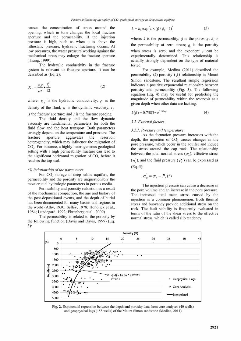
Porosity is also closely related with depth. The porosity values derived from geophysical logs and porosity values from core analyses were plotted against depth (Fig. 2). A reduction in the pore structure due to the effects of compaction and/or cementation was described by Medina (2011).
For the fracture system, the effective fracture aperture dominates the hydraulic response of the system. Excess deformation may open fractures. Fractures may be classified into two broad types: systematic and non-systematic (Singhal and Gupta, 1999). The apertures of fractures can change due to normal stress and shear stress. The injection of CO2
Factors influencing the safety of CO2 geological storage in deep saline aquifers
2921
causes the concentration of stress around the opening, which in turn changes the local fracture aperture and the permeability. If the injection pressure is high, such as when it is above the lithostatic pressure, hydraulic fracturing occurs. At low pressures, the water pressure working against the mechanical stress may enlarge the fracture aperture (Tsang, 1999).
The hydraulic conductivity in the fracture system is relevant to fracture aperture. It can be described as (Eq. 2):
2
12f
f
tgK
s
(2)
where:
fK is the hydraulic conductivity; is the
density of the fluid; is the dynamic viscosity; ft
is the fracture aperture; and s is the fracture spacing. The fluid density and the flow dynamic
viscosity are fundamental parameters for both the fluid flow and the heat transport. Both parameters strongly depend on the temperature and pressure. The fracture aperture aggravates the reservoir heterogeneity, which may influence the migration of CO2. For instance, a highly heterogeneous geological setting with a high permeability fracture can lead to the significant horizontal migration of CO2 before it reaches the top seal. (3) Relationship of the parameters
For CO2 storage in deep saline aquifers, the permeability and the porosity are unquestionably the most crucial hydrologic parameters in porous media.
Permeability and porosity reduction as a result of the mechanical compaction, the age and history of the post-depositional events, and the depth of burial has been documented for many basins and regions in the world (Athy, 1930; Selley, 1978; Hoholick et al., 1984; Lundegard, 1992; Ehrenberg et al., 2009).
The permeability is related to the porosity by the following function (Davis and Davis, 1999) (Eq. 3):
0 0exp ( / 1)k k c
(3)
where: k is the permeability; is the porosity; 0k is
the permeability at zero stress; 0 is the porosity
when stress is zero; and the exponent c can be experimentally determined. This relationship is actually strongly dependent on the type of material tested.
For example, Medina (2011) described the permeability (k)-porosity ( ) relationship in Mount
Simon sandstone. The resultant simple regression indicates a positive exponential relationship between porosity and permeability (Fig. 3). The following equation (Eq. 4) may be useful for predicting the magnitude of permeability within the reservoir at a given depth when other data are lacking.
0.283( ) 0.7583k e (4)
3.2. External factors
3.2.1. Pressure and temperature As the formation pressure increases with the
depth, the injection of CO2 causes changes in the pore pressure, which occur in the aquifer and induce the stress around the cap rock. The relationship between the total normal stress (
n ), effective stress
( 'n ), and the fluid pressure ( fP ) can be expressed as
(Eq. 5):
'n n fP (5)
The injection pressure can cause a decrease in the pore volume and an increase in the pore pressure. The increased total mean stress caused by the injection is a common phenomenon. Both thermal stress and buoyancy provide additional stress on the rock. The fault stability is frequently evaluated in terms of the ratio of the shear stress to the effective normal stress, which is called slip tendency.
Fig. 2. Exponential regression between the depth and porosity data from core analyses (40 wells) and geophysical logs (158 wells) of the Mount Simon sandstone (Medina, 2011)

Qiao and Li/Environmental Engineering and Management Journal 13 (2014), 12, 2917-2928
2922
Fig. 3. Semi-log plot of permeability and porosity data collected at the MRCSP region (Medina, 2011)
For a single fault, the shear strength may be expressed by the Coulomb failure criterion with the following equations (Eqs. 6-7):
( )r n fC P (6)
'n
(if 0C ) (7)
where: is the shear stress along the fault; n
is the normal total stress acting across the fault surface; is the coefficient of static friction; C is
the cohesion; and n is the effective normal stress.
Eq. (6) indicates that increasing fluid pressure during injection may induce shear slip. For a cohesionless
fault ( 0C ), if
'n
the slip is induced. Fig. 4
shows the fault failure with the stress changes. Generally, analytical shear-slip analysis is
based on the magnitude and orientation of the injection principal stress. However, the inflation of a reservoir during injection should also be taken into consideration.
The variation of the heat transport properties depends on the thermodynamic conditions. The temperature change is one of the important indices of the thermodynamic conditions in the system. The large changes in temperature and pressure associated with reservoir exploitation affect the porosity and permeability of the rock as well as the properties of the fluid flowing through the rock mass, which affect the flow and transport of heat in the system (Mcdermott et al., 2006a, 2006b). Pruess (2008) analyzed the heat transfer behavior in the subsurface after leakage from a geologic storage reservoir, as shown in Fig. 5. The temperature changes arising from decompression without heat transfer is known as the Joule-Thomson effect. The CO2 flow is not entirely isenthalpic. CO2 cannot expand to atmospheric pressure without any heat transfer because the expanding and cooling CO2 absorbs heat from the surroundings of the pathway through which it migrates.
However, the rate of the heat supply depends on the properties of the geologic media, particularly the thermal conductivity. If the thermal conductivity of surrounding rock is low, the heat transfer is limited. The heat transfer causes the thermal stress exerted on the reservoir and the top seal, as well as the formation stress, during the injection process.
Under high temperatures, the elasticity and plasticity of the reservoir rock change because of thermal contraction and extension. The inflation of the reservoir is induced by the thermal fracturing that is caused by the thermal stress and heat transport. Taking the inflation of the reservoir into consideration, the failure analysis of the fracture and fault becomes more complex because it is influenced by the additional stress. The fault fails with more ease, even if the effective normal stress only decreases by just a small amount. The injection pressure should be well controlled in practice to avoid causing the sharp fault slip during the sequestration process. Fig. 6 shows the fault failure when the inflation of the reservoir is considered. 3.2.2. Influence of pressure and temperature on other parameters
In deep geothermal CO2 storage fields, several parameters are manifestations of the interaction between the heat transfer and the fluid flow in aquifers. These parameters have a varied response to the pressure and temperature. Different rock types demonstrate different stress-permeability relationships, as illustrated in Fig. 7. The Figure shows the experimental data of the permeability plotted against the effective confining stress from laboratory tests on shale, granite, and low-permeability sandstone.
Heat transport occurs when the permeability is pertinent, and the temperature gradient is another factor that induces the heat flow. A previous study concluded that heat transport is conduction that is typically dominated by the inferred limiting permeability values of <10-17 m2 to <10-15 m2, depending on the geometry and dimensions of the system (Manning, 1999).

Factors influencing the safety of CO2 geological storage in deep saline aquifers
2923
Fig. 4. Stress resolved on a fault and shear slip along a pre-existing fault due to increased fluid pressure
Fig. 5. Specific enthalpy of CO2 (in kJ/kg) as a function of temperature and pressure
Fig. 6. Stress resolved on a fault and shear slip along a pre-existing fault due to inflation of the reservoir
Fig. 7. Relationship between permeability and pressure in three kinds of rock
(Brace et al., 1968; Kilmer et al., 1987; Rutqvist et al., 2003)
Consequently, the depth of the reservoir,
along with the porosity and the permeability distribution, directly affects the radial influence of the pressure buildup within the reservoir/subsurface, as shown in theoretical calculations for saline aquifers during CO2 injection (Birkholzer et al., 2009; Mathias et al., 2009).
3.2.3. Chemical reactions
The CO2 sequestered by injection in a deep brine formation is dissolved in water, thereby allowing CO2–water–rock interactions and forming new minerals that alter the mineralogy and potentially alter the physical aspects of the rock (Watson et al., 2004). These reactions can give rise to local porosity and permeability changes. For
example, the feldspars are dominantly alkali, which have a very slow reaction rate, and the rock fragments are metamorphic (quartz and mica dominated), which also have a very slow reaction rate or are inert to CO2 dissolution. In a high permeability reservoir, the mineralogy of the formation is typically quartz-rich with a minor component of feldspar, clays, or occasional rock fragments. This suite of minerals all have relatively low rates of reaction with CO2 and does not result in any major mineralogical trapping of CO2. However, reservoirs containing substantial amounts of reactive clays (i.e., chlorite and berthierine), nontypical cement phases (i.e., glauconite and laumontite), fine-grained feldspars, and fine-grained rock fragments (i.e.,

Qiao and Li/Environmental Engineering and Management Journal 13 (2014), 12, 2917-2928
2924
ferromagnesium minerals) all react readily due to the lower pH resulting from the CO2 dissolution (Watson, 2005). 4. Discussion 4.1. Multi-process coupling
The integrity of the seal depends not only on the features of the geological media, but also on the processes linking the thermal gradients, hydrologic flow, chemical reactions, and mechanical deformation. These coupled processes play an important role in the safe geological storage of CO2. Fig. 8 shows the linkage of these coupled processes.
The multi-process is coupled by heat and the multiphase fluid flow in geological media, wherein both pressure and temperature control the mechanical behavior of the reservoir and the cap rock.
Fig. 8. Schematic of the coupling processes during CO2 injection
On one hand, the fluid properties, such as
viscosity, density, heat capacity, and heat conductivity, have been treated as functions of pressure and temperature. For example, CO2 has a lower density at higher temperatures, which implies less-efficient use of the available storage pore volume and a stronger buoyancy force driving the migration. The viscosity also decreases with temperature (Audigane, 2007). The reduced viscosity implies a lower resistance to flow and results in the increased migration rates. On the other hand, the hydraulic properties, including the permeability, fracture apertures, and porosity, are changed with increased pressure and temperature. Simultaneously, the thermal parameters related to thermal convection and heat transport change in response to these changes in the hydraulic properties.
The loop chart shows that the pressure and temperature as well as the properties of the fluid and cap rock are the key parts of the system. The influence of the thermal and hydraulic factors causes the mechanical behavior of the cap rock to behave in various ways under different circumstances. The hydraulic process clearly causes different levels of mechanical failure of the cap rock under different relationships between stress and strain, as well as the density and salinity of water.
The thermal process affects the phase changes through the amount of carbon dioxide dissolved as well as the evaporation and the chemical reactions, which depend on the temperature, pressure, and salinity conditions. Therefore, the thermal effect may also cause variations in the geochemical process. For instance, the thermal effects are different on hard cap rock and soft cap rock due to their different expandability and thermal conductivity.
The chemical process in the system also occurs and affects the security of the geological storage once the CO2 is dissolved. Geochemical processes involve two aspects: one is the solubility of CO2, and the other is the reaction between CO2 and the surrounding minerals, which may form new minerals. The chemical process strengthens its relationship with other processes through key connection parameters and properties.
Solubility decreases with increasing temperature and salinity, but increases with pressure (Spycher et al., 2003). The dissolution of the injected CO2 accumulated beneath a low-permeability cap rock increases the water density. The chemical processes influence the system coupling the thermo- and hydro-processes, as well as the mechanism and integrity of the reservoir.
The multi-process coupling can occur in various and complex methods in different reservoir types and under detailed injection scenarios. 4.2. Risk reduction
Suitable technologies that can reliably monitor and detect potential CO2 leakage on the surface are of great value. There are a number of indicators that can potentially confirm the containment potential for carbon capture and storage. (1) Remote sensing method: Spectral remote sensing can provide good area coverage, which is attractive when considering a large surface area that may be affected by potential CO2 seepages from a leaking storage complex. Researchers have investigated the use of spectral remote sensing imagery in detecting potential CO2 occurrences at the surface, should a leakage occur from the subsurface reservoirs where CO2 is stored (Govindan, 2011). Direct methods involve field-based measurement techniques to detect and quantify gas leakage, such as the local soil-sample analyses with an infra-red (IR) gas analyzer, open-path laser measurements, and measurements of CO2 flux (Ciotoli et al., 1999; Jones et al., 2009; Hutchinson and Livingston, 1993). Indirect methods involve studying the effects of leakage on the surface environment, such as the vegetation stress patterns (Pickles and Cover, 2004; Bateson et al., 2008; Keith et al., 2009; Govindan, 2011). (2) Geophysical methods: The movement of faults and/or fractures generates seismic energy. Although analogous to earthquakes, event magnitudes in and

Factors influencing the safety of CO2 geological storage in deep saline aquifers
2925
around reservoirs are significantly lower, so they are termed microearthquakes or microseismic events. The changes in the density, seismic velocity, or electrical resistivity are associated with the changes in the gas saturation and are used in methods to follow up the fate of injected CO2. A migrating CO2 plume may be monitored using various geophysical methods, such as gravity, 4D seismic data processing, electrical resistivity tomography, or CSEM tools, as well as sonic, neutron, nuclear magnetic resonance, and pulsed neutron logging tools.
These methods can detect the initial CO2 breakthrough and possibly the saturation via a distributed thermal perturbation sensor. Acoustic seismic surveys and tests to verify the cap-rock containment can also be applied to minimize the associated risks. More detailed information is described by Fabriol (2011) and by Korre (2011).
(3) Water Sample analysis: The hydrochemical factors may be useful for the detection and quantification of CO2 leakage. The accuracy of the estimates improves with repeated spatio-temporal sampling. For example, a more common indicator is a salinity discontinuity across the cap rock, which separates the water of more saline formations from the water of clearly less saline formation waters. The required evidence for this are the fluid samples from above the cap rock and below the cap rock, followed by a simple analysis of the salinity level and a profile of the saline content. A potential method to provide a quantitative estimate of CO2 leakage is to use a numerical simulator to predict whether a measureable impact on the groundwater occurs given an ingression of leaked CO2 in terms of a change in the TDS content.
5. Conclusions
The injection of CO2 in geological formations
is related to many important factors that influence the security of its long-term geological storage. The internal factors include the cap-rock type and key parameters such as the permeability, porosity, and fracture aperture. Different reservoir and cap-rock types vary in terms of the combination of geological deposits, key strata, thickness, depth, material types, and structure, all of which determine the basic characteristics of a geological formation.
The external factors involve the pressure and temperature as well as their effects on the seal failure, along with the chemical reactions that may occur. The coupled thermo-hydro-mechanical-chemical processes operating on the top seal and reservoir actually determine the integrity of the cap rock. The likelihood of the different mechanisms of cap rock damage is related to the behavior of the multiphase fluid flow and the distribution of the geological structure, which are both influenced by pressure and temperature.
Other hydraulic parameters of the reservoir, such as the permeability, porosity, and facture aperture, and the thermal effects, such as heat transport and thermal convection, also have various effects as the key factors in the stress and strain system.
Before selecting a site for CO2 storage, the geological investigation, data collection, and analysis of the stability of the cap rock as well as the reservoir based on the abovementioned factors can guide future decisions and calculations. References
Athy L.F., (1930), Density, porosity, and compaction of
sedimentary rocks, American Association of Petroleum Geologists Bulletin, 14, 1-24.
Audigane P., Gaus I., Czernichowski-Lauriol I., Pruess K., Xu T.F., (2007), Two dimensional reactive modeling of CO2 injection in a saline aquifer at the Sleipner site, North sea, American Journal of Science, 307, 974h–1008.
Bachu S., (2000), Sequestration of CO2 in geological media: criteria and approach for site selection in response to climate change, Energy Conversion and Management, 41, 953-970.
Bachu S., Adams J.J., (2003), Sequestration of CO2 in geological media in response to climate change: capacity of deep saline aquifers to sequester CO2 in solution, Energy Conversion and Management, 44, 3151–3175.
Bateson L., Vellico M., Beaubien S.E., Pearce J.M., Annunziatellis A., Ciotoli G., Coren F., Lombardi S., Marsh S., (2008), The application of remote sensing techniques to monitor CO2 storage sites for surface leakage: method development and testing at Latera (Italy) where naturally-produced CO2 is leaking to the atmosphere, International Journal of Greenhouse Gas Control, 2, 388-400.
Bentham M., Kirby G., (2005), CO2 Storage in Saline Aquifers, Oil & Gas Science and Technology, 60, 559-567.
Bielinski A., Kopp A., Schütt H., Class H., (2008), Monitoring of CO2 plumes during storage in geological formations using temperature signals: Numerical investigation. International Journal of Greenhouse Gas Control, 2, 319-328.
Brace W.F., Walsh J.B., Frangos W.T, (1968), Permeability of granite under high pressure, Journal of Geophysical Research, 73, 2225-2236.
Brunt R.G., Guswa A.J., Celia M.A., Peters C.A., (2002), Safe storage of CO2 in deep saline aquifers, Environmental Science & Technology, 36, 240A-245A.
Celia M.A., Nordbotten J.M., Court B., Dobossy M., Bachu S., (2011), Field-scale application of a semi-analytical model for estimation of CO2 and brine leakage along old wells, International Journal of Greenhouse Gas Control, 5, 257-269.
Chadwick R.A., Arts R., Bernstone C., May F., Thibeau S., Zweigel P., (2007), Best practice for the storage of CO2 in saline aquifers. Observations and guidelines from the SACS and CO2 STORE projects, British Geological Survey.
Chiaramonte L., Zoback M.D., Friedmann J., Stamp V., (2008), Seal integrity and feasibility of CO2
sequestration in the Teapot Dome EOR pilot:
Qiao and Li/Environmental Engineering and Management Journal 13 (2014), 12, 2917-2928
2926
geomechanical site characterization, Environmental Geology, 54, 1667-1675.
Ciotoli G., Etiope G., Guerra M., Lombardi S., (1999), The detection of concealed faults in the Ofanto basin using the correlation between soil-gas fracture surveys, Tectonophysics, 301, 321-332.
Davis J.P., Davis D.K., (1999), Stress-dependent permeability: characterization and modeling, SPE annual technical conference and exhibition, Houston TX, 3-6 October 1999, volume Sigma: Reservoir Engineering Society of Petroleum Engineers, Houston.
Ehrenberg S.N., Nadeau P.H., Steen O., (2009), Petroleum reservoir porosity versus depth: influence of geological age, American Association of Petroleum Geologists Bulletin, 93, 1281–1296.
Fabriol H., Bitri A., Bourgeois B., Delatre M., Girard J.F., Pajot G., Rohmer J., (2011), Geophysical methods for CO2 plume imaging: Comparison of performances, Energy Procedia, 4, 3604-3611.
Feignier B., Grasso J.R., (1990), Seismicity induced by gas production. I. Correlation of focal mechanisms and dome structure, Pure and Applied Geophysics, 134, 405-426.
Freeze R.A., Cherry J.A., (1979), Groundwater, Prentice-Hall, Englewood Cliffs, NJ, 604.
Ghoodjani E., Bolouri S.H., (2012), A simulation study of CO2 flooding for EOR and sequestration in bottom water-driven reservoir, Environmental Engineering and Management Journal, 11, 747-752.
Govindan R., Korre A., Durucan S., Imrie C.E., (2011), A geostatistical and probabilistic spectral image processing methodology for monitoring potential CO2 leakages on the surface, International Journal of Greenhouse Gas Control, 5, 589-597.
Grimstad A.A., Georgescu S., Lindeberg E., Vuillaume J.F., (2009), Modelling and Simulation of Mechanisms for Leakage of CO2 from Geological Storage, Energy Procedia, 1, 2511–2518.
Hassanzadeh H., Pooladi-Darvish M., Keith D.W., (2005), Modelling of convective mixing in CO2 Storage, Journal of Canadian Petroleum Technology, 44, 43-50.
Herzog H.J., (1999), The Economics of CO2 Capture, In: Greenhouse Gas Control Technologies, Riemer P., Eliasson B., Wokaun A. (Eds.), Elsevier Science Ltd., Amsterdam, 101-106.
Hoholick J.D., Metarko T., Potter P.E., (1984), Regional variations of porosity and cement: St. Peter and Mount Simon Sandstones in Illinois Basin, American Association of Petroleum Geologists Bulletin, 68, 753-764.
Holloway S., (2001), Storage of fossil-fuel-derived carbon dioxide beneath the surface of the earth, Annual Review of Energy and the Environment, 26, 145-166.
Hornung J., Aigner T., (1999), Reservoir and aquifer characterization of fluvial architectural elements: Stubensandstein, Upper Triassic, southwest Germany, Sedimentary Geology, 129, 215-280.
Hornung J., Aigner T., (2002), Reservoir architecture in a terminal alluvial plain: An outcrop analogue study (upper triassic, Southern Germany) Part 1: Sedimentology and petrophysics, Journal of Petroleum Geology, 25, 3-30.
Hutchinson G.L., Livingston G.P., (1993), Use of chamber systems to measure trace gas fluxes. Agricultural Ecosystem Effects on Trace Gases and Global Climate Change, ASA Special Publication, 55, 63-78.
IPCC, (2007), Climate Change 2007: the Physical Science Basis. IPCC Fourth Assessment Report, Solomon S.,
Qin D., Manning M., Marquis M., Averyt K., Tignor M.M.B., Miller H.L. (Eds.), Cambridge University Press, Cambridge, New York, Melbourne, Madrid, Cape Town, Singapore, São Paolo, Delhi.
Jones D.G., Barlow T., Beaubien S.E., Ciotoli G., Lister T.R., Lombardi S., May F., Moller I., Pearce J.M., Shaw R.A., (2009), New and established techniques for surface gas monitoring at onshore CO2 storage sites, Energy Procedia, 1, 2127-2134.
Keith C.J., Repasky K.S., Lawrence R.L., Jay S.C., Carlsten J.L., (2009), Monitoring the effects of a controlled subsurface carbon dioxide release on vegetation using a hyperspectral imager, International Journal of Greenhouse Gas Control, 3, 626-632.
Kilmer N.H., Morrow N.R., Pitman J.K., (1987), Pressure sensitivity of low permeability sandstones, Journal of Petroleum Science and Engineering, 1, 65-81.
Klingbeil R., Kleineidam S., Asprion U., Aigner T., Teutsch G., (1999), Relating lithofacies to hydrofacies: Outcrop-based hydrogeological characterisation of Quaternary gravel deposits, Sedimentary Geology, 129, 299-310.
Koide H., Tazaki Y., Noguchi Y., Nakayama S., Iijima M., Ito K., Shindo Y., (1992), Subterranean containment and long-term storage of carbon dioxide in unused aquifers and in depleted natural-gas reservoirs, Energy Conversion and Management, 33, 619-626.
Korre A., Imrie C.E., May F., Beaubien S.E., Vandermeijer V., Persoglia S., Golmen L., Fabriol H., Dixon T., (2011), Quantification techniques for potential CO2 leakage from geological storage sites, Energy Procedia, 4, 3413-3420.
Kreft E., Bernstone C., Meyer R., May F., Arts R., Obdam A., Svensson R., Eriksson S., Durst P., Gaus I., van der Meer B., Geel C., (2007), The Schweinrich structure”, a potential site for industrial scale CO2 storage and a test case for safety assessment in Germany, International Journal of Greenhouse Gas Control, 1, 69-74.
Lindeberg E., (1997) Escape of CO2 from aquifers, Energy Conversion and Management, 38, 235-240.
Liu K.Y., Paterson L., Wong P., Qi D.S., (2002), A sedimentological approach to upscaling, Transport in Porous Media, 46, 285-310.
Lundegard P.D., (1992), Sandstone porosity loss; a “big picture” view of the importance of compaction, Journal of Sedimentary Petrology, 62, 250-260.
Manning C.E., Ingebritsen S.E., (1999), Permeability of the continental crust: implications of geothermal data and metamorphic systems, Reviews of Geophysics, 37, 127-150.
McDermott C.I., Londemann M., Ghergut I., Tenzer M., Kolditz O., (2006a), Investigation of coupled hydraulic–geomechanical processes at the KTB site: pressure-dependent characteristics of a long-term pump test and elastic interpretation using ageomechanical facies model, Geofluids, 6, 67-81.
McDermott C.I., Kolditz O., (2006b), Geomechanical model for fracture deformation under hydraulic, mechanical and thermal loads, Hydrogeology Journal, 14, 485-498.
McDermott C.I., Xie M., Kosakowski G., Mettier R., Moog H., Kolditz O., (2007), Geomechanical Facies Concept and the Application of Hybrid Numerical and Analytical Techniques for the Description of HTMC Coupled Transport in Fractured Systems, Proceedings, Third-Second Workshop on Geothermal Reservoir Engineering, January 22-24, Stanford University, Stanford, California, USA.
Factors influencing the safety of CO2 geological storage in deep saline aquifers
2927
McGrail B.P., Schaef H.T., Glezakou V.-A., Dang L.X., Owen A.T., (2009), Water reactivity in the liquid and supercritical CO2 phase: has half the story been neglected?, Energy Procedia, 1, 3415-3419.
Medina C.R., Rupp J.A., Barnes D.A., (2011), Effects of reduction in porosity and permeability with depth on storage capacity and injectivity in deep saline aquifers: A case study from the Mount Simon Sandstone aquifer, International Journal of Greenhouse Gas Control, 5, 146-156.
Nogues J.P., Court B., Dobossy M., Nordbotten J.M., Celia M.A., (2012), A methodology to estimate maximum probable leakage along old wells in a geological sequestration operation, International Journal of Greenhouse Gas Control, 7, 39-47.
Okwen R.T., Stewart M.T., Cunningham J.A., (2010), Analytical solution for estimating storage efficiency of geologic sequestration of CO2, International Journal of Greenhouse Gas Control, 4, 102-107.
Okwen R.T., Stewart M.T., Cunningham J.A., (2011), Temporal variations in near-wellbore pressures during CO2 injection in saline aquifers, International Journal of Greenhouse Gas Control, 5, 1140-1148.
Pickles W.L., Cover W.A., (2004), Hyperspectral Geobotanical Remote Sensing for CO2 Storage Monitoring, In: Carbon Dioxide Capture for Storage in Deep Geologic Formations, Benson S.M. (Ed.), Elsevier Ltd., Oxford, vol. II, 1045-1070.
Preston C., Monea M., Jazrawi W., Brown K., Whittaker S., White D., Law D., Chalaturnyk R., Rostron B., (2005), IEA GHG Weyburn CO2 monitoring and storage project, Fuel Processing Technology, 86, 1547–1568.
Propp W.A., Carleson T.E., Wai C.M., Taylor P.R., Daehling K.W., Huang S., Abdel-Latif M., (1996), Corrosion in Supercritical Fluids, US Department of Energy Report DE96014006, Washington DC.
Pruess K., (2008), On CO2 fluid flow and heat transfer behavior in the subsurface, flowing leakage from a geologic storage reservoir, Environmental Geology, 54, 1677-1686.
Pruess K., Garcia J., (2002), Multi-phase flow dynamics during CO2 disposal intosaline aquifers, Environmental Geology, 42, 282-295.
Rea J., Knight R., (1998), Geostatistical analysis of groundpenetrating radar data: A means of describing spatial variation in the subsurface, Water Resource Research, 34, 329-340.
Rohmer J., Bouc O., (2010), A response surface methodology to address uncertainties in cap rock failure assessment for CO2 geological storage in deep aquifers, International Journal of Greenhouse Gas Control, 4, 198-208.
Russick E.M., Poulter G.A., Adkins C.L.J., Sorensen N.R., (1996), Corrosive effects of supercritical carbon dioxide and cosolvents on metals, The Journal of Supercritical Fluids, 9, 43-50.
Rutqvist J., Birkholzer J., Cappa F., Tsang C.-F., (2007), Estimating maximum sustainable injection pressure during geological sequestration of CO2 using coupled fluid flow and geomechanical fault-slip analysis, Energy Conversion and Management, 48, 1798-1807.
Rutqvist J., Birkholzer J., Tsang C.-F., (2008), Coupled reservoir-geomechanical analysis of the potential for tensile and shear failure associated with CO2 injection in multilayered reservoir-cap-rock systems. International Journal of Rock Mechanics and Mining Sciences, 45, 132-143.
Rutqvist J., Tsang C.-F., (2002), A study of cap-rock hydromechanical changes associated with CO2 injection into a brine formation, Environmental Geology, 42, 296-305.
Rutqvist J., Tsang C.-F., (2005), Coupled Hydromechanical Effects of CO2 Injection, In: Underground Injection Science and Technology, Tsang C.F., Apps J.A. (Eds.),, Elsevier, Amsterdam, 649-679.
Rutqvist J., Wu Y.-S., Tsang C.-F., Bodvarsson G.A., (2002), Modeling approach for analysis of coupled multiphase fluid flow, heat transfer, and deformation in fractured porous rock, International Journal of Rock Mechanics and Mining Sciences, 39, 429-442.
Rutqvist J., Stephansson O., (2003), The role of hydromechanical coupling in fractured rock engineering, Hydrogeology Journal, 11, 7-40.
Selley R.C., (1978), Porosity gradients in North Sea oil-bearing sandstones, Journal of the Geological Society, London, 135, 119-132.
Singhal B.B.S., Gupta R.P., (1999), Applied Hydrogeology of Fractured Rocks, Kluwer Academic Publisher, Dordrecht, The Netherlands.
Sminchak J., Gupta N., (2003), Aspects of induced seismic activity and deep-well sequestration of carbon dioxide, Environmental Geosciences, 10, 81–89.
Smith J., Durucan S., Korre A., Shi J.Q., (2011), Carbon dioxide storage risk assessment: Analysis of caprock fracture network connectivity, International Journal of Greenhouse Gas Control, 5, 226-240.
Spycher N., Pruess K., Ennis-King J., (2003), CO2-H2O mixtures in the geological sequestration of CO2. I. Assessment and calculation of mutual solubilities from 12 to 100°C and up to 600 bar, Geochimica et Cosmochimica Acta, 67, 3015-3031.
Stephens M., (1994), Architectural element analysis within the Kayenta Formation (Lower Jurassic) using ground-probing radar and sedimentological profiling, southwestern Colorado, Sedimentary Geology, 90, 179-211.
Streit J.E., Hillis, R.R., (2003), Building Geomechanical Models for the Safe Underground Storage of Carbon Dioxide In Porous Rock, In: Greenhouse Gas Control Technologies, Gale J., Kaya Y., (Eds.), Elsevier Science, Amsterdam, The Netherlands, 495-500.
Streit J.E., Watson M.N., (2004), Estimating Rates of Potential CO2 Loss from Geological Storage Sites for Risk and Uncertainty Analysis, Paper 152, presented at 7th International Conference on Greenhouse Gas Control Technologies, 5–9 September, Vancouver, Canada,.
Tsang C.-F., (1999), Linking thermal, hydrological, and mechanical processes in fractured rocks, Annual Review of Earth and Planetary Sciences, 27, 359-384.
Vasco D.W., Ferretti A., Novali F., (2008a), Etimating permeability from quasi-static deformation: Temporal variations and arrival time inversion, Geophysics, 73, 37-52.
Vasco D.W., Ferretti A., Novali F., (2008b), Reservoir monitoring and characterization using satellite geodetic data: Interferometric Synthetic Aperture Radar observations from the Krechba field, Algeria, Geophysics, 73, WA113-WA122.
Watson M.N., Boreham C.J., Tingate P.R., (2004), Carbon dioxide and carbonate cements in the Otway Basin: implications for geological storage of carbon dioxide, APPEA Journal, 44, 703–720.
Watson M.N., Gibson-Poole C.M., (2005), Reservoir Selection for Optimised Geological Injection and

Qiao and Li/Environmental Engineering and Management Journal 13 (2014), 12, 2917-2928
2928
Storage of Carbon Dioxide: A Combined Geochemical and Stratigraphic Perspective, CRC for Greenhouse Gas Technologies (CO2CRC), Australian School of Petroleum, The University of Adelaide, SA 5005, Australia.
Watts N.L., (1987), Theoretical aspects of cap-rock and fault sealsfor single-and two-phase hydrocarbon columns, Marine and Petroleum Geology, 4, 274-307.
White C.M., Strazisar B.R., Granite E.J., Hoffman J.S., Pennline H.W., (2003), Separation and capture of CO2 from large stationary sources and sequestration in geological formations: coal beds and deep saline aquifers, Journal of the Air and Waste Management Association, 53, 645-715.
Wildenborg T., (2001), Safety assessment methodology for carbon dioxide sequestration (SAMCARDS), In: CO2 Capture Project (CCP) SMVWorkshop, Geo-ForschungsZentrum, Potsdam, Germany.
William C., Svec J.R., (2010), Experimental investigation of wellbore integrity and CO2–brine flow along the casing–cement microannulus, International Journal of Greenhouse Gas Control, 4, 272-282.
Zhang M. and Bachu S., (2011), Review of integrity of existing wells in relation to CO2 geological storage: What do we know?, International Journal of Greenhouse Gas Control, 5, 826-840.


![Factors influencing[1]](https://img.pdfslide.us/doc/110x75/54be1c8d4a795948378b4597/factors-influencing1.jpg)