Embed Size (px)
Citation preview
Facilities Management
Technical Standards
September 2, 2016
Edition 2.0
Co-Editors
Robert J. Avalle, EIT
Wayne W. Boy, P.E.
Haskell C. Brown Jr., RA
Robert P. Dillman, P.E.
Van Dobson, P.E.
Troy R. Knapp, P.E.
Richard S. Phillips. P.E.
David W. Rudloff, P.E.
Dave B. Shepard, P.E.
Gregg Shipp, P.E.
Steven W. Stafford, P.E.
This publication represents the combined efforts and professional expertise of the directors, superintendents,
managers, craftspeople, and other staff members throughout Facilities Management and the Code Review Team.
Without their valuable contributions and careful review, the Facilities Management Technical Standards would
not have been possible.
TABLE OF CONTENTS
Vision Statement……………………………………………………..….… 1
Foreword………………………………………………………………...… 2
Introduction……………………………………………………………...… 3
GR General………………………………………………………….….… 4
GR1 General Information……………………………………….…... 4
GR2 Coordination Requirements……………………………………. 8
DR General Design Requirements….……………………..………….….. 9
DR 1 Design Principals…...…….…………………..……………..… 9
DR 2 Site Planning……………………………..…………………..… 10
DR 3 Functional and Space Planning Requirements…………..…….. 10
DR 4 Building Dedication Plaques…………………………………... 19
HP Historic Preservation………………………………………………….. 20
HP 1 General Information…………………………………………..... 20
HP 2 Archaeological Concerns…………………..…………………... 20
TS Technical Standards…..…………………………………………....…. 21
02 00 00 Existing Conditions..……………………………………….. 21
03 00 00 Concrete……………………………………………………. 22
04 00 00 Masonry…………………………………………………..... 23
06 00 00 Wood, Plastics, and Composites…………………………... 25
07 00 00 Thermal and Moisture Protection………………………….. 26
08 00 00 Openings………………………………………..………….. 30
09 00 00 Finishes…………………………………………..………… 34
10 00 00 Specialties…………………………………………..……… 38
12 00 00 Furnishings………………………………………..……….. 40
14 00 00 Conveying Equipment……………………………..………. 41
21 00 00 Fire Suppression…………………………………..……….. 43
22 00 00 Plumbing…………………………………………….…….. 46
23 00 00 Heating, Ventilating, and Air Conditioning…………….…. 50
26 00 00 Electrical…………………………………………………... 70
27 00 00 Communications…………………………………………... 79
28 00 00 Electronic Safety and Security…………………………….. 80
31 00 00 Earthwork………………………………………………….. 85
32 00 00 Exterior Improvements…………………………………….. 87
33 00 00 Utilities……………………………………………………... 92
1
Vision Statement
A Vision Statement for the Planning and Design
of the College of William and Mary
Buildings and Grounds
The College of William & Mary occupies a hallowed place in the history of the nation and, more
specifically, in the development of the American collegiate campus. The planning and design
principles embodied in the early planning concepts of the university established precedents with
far reaching influence - a legacy which we will continue and enhance.
These standards enable the technical translation of the concepts contained in the Campus Design
Guidelines Report (May, 2003) into state of the art building systems; and, for the first time,
codify technical criteria for all future design. These standards express the College of William
and Mary application of university unique discretionary criteria/technical options consistent with
the requirements of the Virginia Uniform Statewide Building Code. Application of the these
standards is intended to accomplish the following objectives:
Codify technical design standards for all building systems.
Enable consistent and uniform application of standards in all future design.
Facilitate future operations and maintenance through judicious life cycle engineering which
begins with the end in mind.
Provide a framework that will be adjusted, as required, to keep pace with pedagogical,
technological, and regulatory change.
Create buildings, building systems and supporting infrastructure equal to the quality of our
students, faculty and staff, and perpetuate a heritage of excellence.

2
Foreword
The College of William and Mary Facilities Management Technical Standards have been
prepared to guide and assist architectural and engineering consultants and Facilities Management
staff in the planning, design and preparation of design documents for construction and renovation
of the university’s facilities.
The Standards in this publication identify specific or unique standards and requirements for
university projects and the ‘lessons learned’ from previous projects. As such, the Standards
supplement and are in addition to mandatory codes, industry standards and other authoritative
resources applicable under the laws of the Commonwealth of Virginia and the Federal
Government.
There may be particular project circumstances that, in the judgment of the Architect or Engineer,
warrant alternatives to these Standards. Such recommendations are welcome and will be
conscientiously considered. However, unless the university Associate Vice President (AVP),
Facilities Management gives special approval for alternatives prior to implementation, the
Architect and/or Engineer must comply with the Standards as stated in this publication.
Recommendations for alternatives to these standards shall be submitted to the AVP, Facilities
Management in a Determination and Findings format via the Director of Facilities Planning,
Design and Construction and the Director of the Code Review Team (CRT).
Recommendations are welcome from Standards users for additions and modifications.
Please submit any comments to the Director, Facilities Planning, Design, and Construction.
For information related to Facilities Management, visit the website
http://www.wm.edu/offices/facilities/index.php
Van Dobson, P.E.
Associate Vice President for
Facilities Management
3
Introduction
The Facilities Management Technical Standards are intended for the use of architects,
landscape architects, and engineers involved in the preparation of construction documents for the
university. The Standards are a reference for facilities project managers and other personnel
whose responsibilities include implementing institutional lessons-learned through design,
construction and in-house services.
The Standards provide procedural and technical requirements broadly applicable to all design
and construction. As part of the contractual agreement between the design professional and the
university, conscientious application of the Standards is a tool to expedite the design and
construction process in a cooperative, partnering effort. In like manner, Facilities Management
personnel are responsible for executing the intent of the Standards.
The format of this second edition of the university’s Standards is intended to be user friendly,
with an emphasis on a pre-design understanding for a partnering effort between architect,
engineer, end user, and a variety of facilities personnel under the responsibility of the Project
Manager.
These Standards, and any added supplements, shall be followed for all projects unless due
process is used for waivers or modifications. It is intended that the Standards be incorporated,
not simply referenced, into the design documents.
Periodic supplements to these Standards may be published and distributed to anyone on record as
having a copy of the Standards. Individuals interested in being added to or removed from the
distribution list for these Standards may forward their request to Ms. Jamee Kuehner at
[email protected], 757-221-2245.

4
GR General Requirements
GR 1 General Information
GR 1.1 Application: University Facilities Management Technical Standards shall apply
to all design projects. The Standards are to be incorporated into the design and
construction documents; not simply referenced.
GR 1.1.1 Relief from College of William & Mary Technical Standards: The College of
William and Mary Technical Standards (CWMTS) are intended to supplement the
Virginia Uniform Statewide Building Code and codify minimum technical criteria and
standards to be implemented as applicable in all design projects for the College of
William and Mary. If for any reason any section of the CWMTS is determined to be
impractical to implement, relief from the specific requirement can be requested by
submitting a Determination & Finding (D&F) to the university CRT. The D&F may be
initiated by the consulting A/E or the university Project Manager (PM).
1. Architect/Engineer of Record: Signature on the D&F is optional at the discretion of
the university PM.
GR 1.2 Determination and Findings
GR 1.2.1 Purpose: Determination & Findings are used to document and approve:
1. Deviations from and interpretations of the College of William & Mary Technical
Standards
2. Interpretations of College of William and Mary Erosion and Sediment Control
Standards
3. Code Modifications
4. Code interpretations
5. College Building Official (CBO) determinations of application of current code to
existing structures
GR 1.2.2 Responsibility
1. Architect & Engineer of Record: Compliance with the Virginia Uniform Statewide
Building Code (VUSBC) and the university Technical Standards is the responsibility
of the Architect and Engineer of record. When compliance is not technically feasible
or a determination or interpretation is required, the A/E of Record or university PM
shall identify the need and submit the appropriate D&F.
2. University CRT: The university CRT will review submitted documents for
compliance with the VUSBC and the university Technical Standards and identify
discrepancies not identified by the A/E or university PM. The A/E shall either
comply with the identified code or technical standard or submit a D&F documenting
the need and purpose of the deviation.
5
GR 1.2.3 Preparation: The need for a Determination & Finding shall be identified by the
A/E of Record and/or the university PM. The Determination & Findings form shall be
prepared by the A/E of Record or the university PM. The preparer shall:
1. Identify the type of D&F and approving authority (Note pull down menu in D&F
Title)
2. Identify all parties who are required to sign the D&F.
3. Identify the action requested. The request shall be specific and identify the applicable
code or technical standard by name and number.
4. Provide all pertinent project information
5. Provide background information. The information shall be concise and specific to the
request. The reason for the request shall be identified in this section of the D&F.
6. Provide the Determination. The determination shall identify the options and the
associated pros and cons
7. Provide the Finding. The finding shall include the proposed resolution, as well as the
reason for the proposed resolution.
8. Provide the anticipated impact to project in terms of time and money saved by
approving the D&F.
GR 1.2.4 Approval Process: The university PM is responsible for submitting the D&F to
the university CRT and obtaining the approving signatures for all D&F’s within 2 weeks
once the need for the Determination & Finding is identified. The final approving
authority for Determination and findings is:
1. Code and Life Safety related issues - CBO
2. Erosion and Sediment control issues - Director of Facilities Planning, Design and
Construction.
3. Technical Standards (CWM Campus) - AVP for Facilities Management.
4. Technical Standards (VIMS Campus) – Director, Facilities Management
GR 1.2.5 Tracking: The university CRT shall track and report the status of Determination &
Findings to the CBO and AVP for Facilities Management on a weekly basis.
GR 1.2.6 Blank Form and Examples: A blank Determination & Findings form can be
found at: http://www.wm.edu/offices/facilities/services/fpdc/forms/index.php
GR 1.3 Definitions/Terms
GR 1.3.1 University Grounds
6
1. College of William and Mary: Inclusive of all State owned or leased property
comprising the Main Campus and any Satellite Campus representing the College of
William and Mary and the Virginia Institute of Marine Science. Agency Codes are:
204 – Ash Lawn
204 – College of William and Mary
268 – Virginia Institute of Marine Science
2. Historic Campus – Area bounded by Richmond Road, Jamestown Road and the
fence to the west of the Wren Building.
3. North Campus – Area bounded by the Sunken Garden on the south, Richmond Road
on the north, the north branch of Crim Dell on the west, including properties along
the north side of Richmond Road.
4. South Campus – Area bounded by the Sunken Garden and Crim Dell on the north,
Jamestown Road on the south, Lake Matoaka on the west and including properties
along the south side of Jamestown Road.
5. Law School Precinct – Area bounded by Newport Avenue on the north, South Henry
Street on the west, McCormack-Nagelson Tennis center on the south and Colonial
Parkway on the east.
6. School of Education Precinct – Area bounded by Monticello Avenue to the North,
Mount Vernon Avenue to the East, Matoaka Court to the South and Compton Drive
to the West.
7. West Woods – Area bounded by the north branch of Crim Dell on the east, the main
branch of Crim Dell and Lake Matoaka on the south, Brooks Street and Lake
Matoaka on the west and the residences along College Terrace on the north.
8. Old Campus – Diamond-shaped area around the Sunken Garden bounded on the
north by Richmond Road and a line from Blow Hall to the now-closed portion of
James Blair Drive, on the east by the Historic Campus, on the south by Jamestown
Road and Landrum Drive and on the west by Crim Dell and the now-closed portion
of James Blair Drive. This area is split and encompassed partially in the North
Campus and partially in the South Campus areas.
9. Dillard Complex – Area located at the intersection of Ironbound Road and Longhill
Connector, approximately one-and-one-half miles from the main campus.
GR 1.3.2 Architect/Engineer
1. "Architect/Engineer" as used in these Standards is the Architect or Engineer of
record who contracts with the university as the prime design professional to provide
architectural or engineering services for a project. The term includes any associates
or consultants employed by the Architect/Engineer of record in the provision of
project design services.
7
GR 1.3.3 University PM/Construction Manager/CRT
1. “Project Manager” as used in these Standards, unless otherwise defined, is
synonymous with “university PM”, the designated Facilities Management person
responsible to the Building Committee and university administration for the
management of project design and construction within the established scope, budget
and schedule. The PM is the university’s designated contact person for the
Architect/Engineer.
2. “Construction Manager” as used in these Standards, unless otherwise defined, is the
Facilities Management person responsible to the Director, Facilities Planning, Design,
and Construction for administration of construction, project inspection, and
coordination with other university persons or entities related to utilities,
communications, and information technology.
3. “CRT” as used in these Standards, unless otherwise defined, is the university team
responsible to the Building Official for review of project submissions to ensure that
the contract documents are prepared in accordance with the university’s Facilities
Management Technical Standards and applicable codes.
GR 1.3.4 Standards vs. Code:
Where these Technical Standards exceed code or legal requirements, the Technical
Standards shall govern.
8
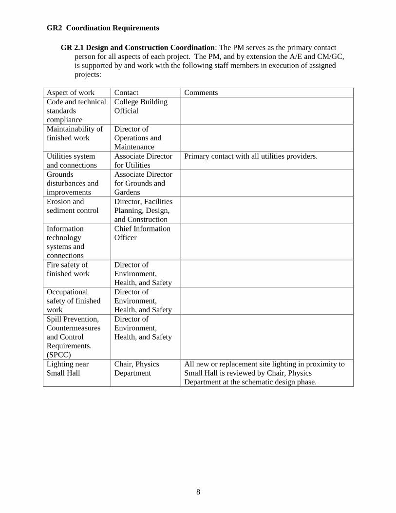
GR2 Coordination Requirements
GR 2.1 Design and Construction Coordination: The PM serves as the primary contact
person for all aspects of each project. The PM, and by extension the A/E and CM/GC,
is supported by and work with the following staff members in execution of assigned
projects:
Aspect of work Contact Comments
Code and technical
standards
compliance
College Building
Official
Maintainability of
finished work
Director of
Operations and
Maintenance
Utilities system
and connections
Associate Director
for Utilities
Primary contact with all utilities providers.
Grounds
disturbances and
improvements
Associate Director
for Grounds and
Gardens
Erosion and
sediment control
Director, Facilities
Planning, Design,
and Construction
Information
technology
systems and
connections
Chief Information
Officer
Fire safety of
finished work
Director of
Environment,
Health, and Safety
Occupational
safety of finished
work
Director of
Environment,
Health, and Safety
Spill Prevention,
Countermeasures
and Control
Requirements.
(SPCC)
Director of
Environment,
Health, and Safety
Lighting near
Small Hall
Chair, Physics
Department
All new or replacement site lighting in proximity to
Small Hall is reviewed by Chair, Physics
Department at the schematic design phase.
9
DR General Design Requirements
DR 1 Design Principles
DR 1.1 University Design Guideline Report: The building exterior shall be consistent with
the university Design Guideline Report (the Guidelines) referenced in the vision
statement at the beginning of these standards. The Guidelines encourage unity in design
over time, while simultaneously allowing flexibility for positive innovation.
1. Architectural Objectives: Five objectives should be considered in determining the
architectural expression of each new building, addition or renovation to create a
continuum of design across the campus from east (most traditional) to west
(transitional):
a. Unified Architectural and Landscape Character: The campus architectural
and landscape character should be unified. Within this objective, four criteria
should guide design:
Proximity to the Old Campus and/or Jamestown Road
Architectural characteristics of the existing neighboring buildings
Proposed use and scale of the new building
Hierarchical position within the campus plan
b. Preservation of the Old Campus Character: The architectural
configuration and character of the Old Campus should be preserved.
c. Public Space Creation and Circulation: New public spaces on the campus
should be created and connected by clearly articulated pedestrian circulation
paths. New public buildings should create and frame new public spaces
whenever possible.
d. Removal of Existing Barriers: Existing barriers to unifying the campus,
such as roads and parking should be removed (or at least minimized) wherever
possible.
e. Ravine Preservation and Enhancement: The unique naturalistic attributes
of the Ravine intervening within the campus landscape should be preserved
and enhanced.
2. Engineering Objectives:
a. Fifty Year Building Structures: Building structures/envelopes shall
incorporate materials and detailing consistent with a building life span of not
less than 50 years.
b. Optimized Energy Conservation: Energy conservation and management
shall be optimized through a complete and rigorous analysis of life cycle
costs.
c. LEED Application: Environmental sensitivity will be recognized thru
application of the LEED process to achieve LEED Silver certification in terms
of actual design. Registration and formal acknowledgement of this
engineering sensitivity is not required beyond documentation of the LEED
points achieved during design.

10
DR 1.2 Service Life: Service life of various buildings and facilities is defined as follows:
1. Permanent construction: Permanent construction will be designed and constructed
to serve a life expectancy of 50 years or more, will be energy efficient, and will
include finishes, materials, and systems selected for low maintenance and low life
cycle costs.
2. Semi-permanent construction: Semi-permanent construction will be designed and
constructed to serve a life expectancy of more than 5 years but less than 50 years
(generally a 25 year service life), will be energy efficient, and will include finishes,
materials, and systems selected for moderate degree of maintenance using the life-
cycle approach.
3. Temporary construction: Temporary construction will be designed and constructed
to serve life expectancy of 5 years or less, will use low cost construction, and systems
selected with maintenance factors being a secondary consideration.
DR 2 Site Planning
DR 2.1 Building Height
1. Maximum Height: Building height shall be no higher than 45 feet above the
highest grade line.
2. Exceptions: Where exceptions are granted, the A/E shall confirm with the Federal
Aviation Association (FAA) that the building does not interfere with the approach
paths to the Williamsburg Community Airport. Written confirmation shall be
provided to the university at the Schematic Design Phase.
DR 2.2 Parking
1. Prohibited: Parking under a building and parking within 20 feet of a building are
prohibited.
DR 2.3 Loading Docks and Service Access
1. Prohibited: Internal loading docks are prohibited.
2. Service Access: In the absence of a loading dock, provisions are to be made to
provide service access to the street side of the building. At a minimum one or more
service parking spaces should be provided on the street side of the building.
DR 2.4 Equipment Screening: Equipment located at grade level shall be screened from
view of other buildings, streets, and walkways.
DR 3 Functional and Space Planning Requirements
DR 3.1 Space Guidelines: The following State Council of Higher Education for Virginia
(SCHEV) space guidelines shall be used for the planning of all university facilities:
1. Vice Presidents: 300 net square feet (NSF)
11
2. Deans, Associate Vice Presidents: 200 net square feet
a. Includes Assistant Vice Presidents, Directors reporting to Vice Presidents and
the President
3. Administrative and Faculty Offices: a. Full Time employees: 110 net square feet
b. Temporary Employees: Coordinate with PM for allowable square footage
4. Support Spaces (clerical, conference and reception) and Administrative Offices: a. 00-05 Full Time Employees (FTE) 30 NSF per FTE, plus 120 NSF
b. 06-15 Full Time Employees 30 NSF per FTE, plus 200 NSF
c. 16-25 Full Time Employees 30 NSF per FTE, plus 50 NSF
d. 25 and over 30 NSF per FTE
5. Open Office Circulation: 15% net square feet in addition to normal allowance
DR 3.2 Room Number Assignment Procedure
1. Approved Room Numbers: All accessible enclosed spaces must have (SCHEV)
room numbers assigned by the Facilities Management's Planning, Design and
Construction Department during design. The approved room numbers provided by
the PM shall be incorporated in the construction document (95%) submission.
2. Room Numbering Format: Room numbers must be unique within the building.
(This means the entire building, even if the project is an addition). Assign room
numbers by floors as follows:
a. 0xxx - Basement or underground level
b. 1xxx - ground or first floor
c. 2xxx - second floor
d. 3xxx - third floor; etc.
3. Designated Start Point: Number rooms consecutively from the designated start
point. The start point is to be designated by the PM based on the building layout.
4. Stacked Rooms: Assign room numbers consistently on each floor so that similar
numbers are stacked above each other, e.g., rooms 3020 and 2020 are located above
room 1020.
5. Even/Odd Room Numbers: Assign even numbered rooms are on one side of the
corridor and odd numbered rooms on the other. Skip numbers if necessary so that
odd and even consecutive numbers are across the hall in proximity to each other.
6. Parallel Corridors: When you have parallel corridors with rooms in the space
between corridors, assign the right corridor consecutive odd numbers and the left
corridor consecutive even numbers. The objective would be to have the last odd
numbered room adjacent to its next consecutive even numbered room in the corridor
at the far end of the building.
12
7. All Spaces: Assign every space a room number, including toilets, janitor closets,
mechanical, electrical, telecommunications, and circulation, e.g., vestibules, lobbies,
corridors, elevators, etc.
8. Sub-Spaces: Assign spaces inside rooms the same number as on the hallway door,
except with a suffix, e.g., 201 main room, 201A supervisor office, 201B file room,
201J janitor closet, etc.
9. Specialty Rooms: Assign specialty rooms with suffixes as follows:
a. 201E electrical
b. 201J janitor closet
c. 201L elevator
d. 201M mechanical
e. 201P circulation (corridors or lobbies)
f. 201S stair
g. 201T toilet
h. 201V vestibule
i. 201Z (telecommunications/data)
DR 3.3 Room-Specific Requirements
DR 3.3.1 Custodial Rooms
DR 3.3.1.1 Primary Custodial Rooms: Provide one primary custodial room in each
building on main level and centrally located to accommodate the size and needs of the
building. This room should be a minimum of 120 SF.
1. Features to Include: The primary custodial room shall contain the following
features:
a. Open Floor Space: Open floor space sufficient in area to provide storage for
a custodian cart and floor machines.
b. Wall Shelves: Minimum of two (2) stainless steel wall shelves being
approximately 5 ft long x 14 inches deep with a minimum of 18 inches
separation between the shelves; the upper shelf shall not be higher than 6’
from the floor.
c. Broom & Mop Hangers: Broom and mop hangers to be mounted on the wall
(number to be determined by size of facility).
d. Lockers: Space for a minimum of two stacked locker units.
e. Electrical Outlet: Two (2) GFCI type duplex electrical outlets centered 18
inches above the floor in accessible locations (on wall adjacent to corridor
door).
e. Exhaust: See “23 05 00 - Common Work Results for HVAC” for minimum
exhaust requirements.
2. Items to Exclude: No plumbing or fire sprinkler system control valves, electric,
data, or alarm panels shall be located in any space specifically constructed for
custodial services. Custodial rooms shall open on to a hallway and shall not open into
a restroom.
13
DR 3.3.1.2 Additional Custodial Rooms: In addition to the primary custodial room, provide
at least one custodial room on each floor including the main level. For initial planning
purposes, provide one additional room for each approximately 15,000 SF of floor area.
The final number of rooms and their sizes will be determined after consultation with the
Director of Building Services after preliminary layout of facility has been determined by
the designer.
1. Features to Include: The auxiliary custodial closets will consist of:
a. Open Floor Space: Each room shall be approximately 80 SF minimum.
Exact locations will be determined by after consultation with the Director of
Building Services.
b. Cart Space: Approximately 20 SF of open floor space to accommodate a
custodial cart and equipment.
c. Service Sink: One floor mounted service sink in back corner of room.
Provide heavy duty hot and cold water faucets with backflow preventers or
vacuum breakers. Walls surrounding sink shall be ceramic tile and extend four
(4) feet high and one (1) foot along each wall from the sink.
d. Wall Shelves: Minimum of two (2) stainless steel wall shelves being
approximately 5 ft long x 14 inches deep with a minimum of 18 inches
separation between the shelves; the upper shelve shall not be higher than 6’
from the floor.
e. Broom & Mop Hangers: Broom and mop hangers to be mounted on the
walls (number to be determined by size of facility).
f. Electrical Outlets: At least one (1) GFCI type duplex electrical outlet
centered 18 inches above the floor in accessible location (preferably on wall
adjacent to corridor door).
g. Exhaust: See “23 05 00 - Common Work Results for HVAC” for minimum
exhaust requirements.
DR 3.3.2 Recycling Rooms
1. Where Required: Each floor of new construction shall provide for space for
recycling activities. Specific requirements for space will be dependent upon building
size, use, and configuration.
2. Preliminary Planning: The following guidelines may be used for preliminary
planning:
a. Size: 80 square foot room near or adjoining a loading dock or primary service
door.
b. Shelving: Minimum of one (1) floor space 16 inches by 52 inches to
accommodate paper storage shelving in each departmental or functional area.
Paper storage is preferred in copy rooms.
c. Container Space: Minimum of one (1) floor space 24 inches by 24 inches on
each floor of each wing to accommodate recycling waste stream. Beverage
container space is preferred in vending, lunch or kitchen areas.
14
DR 3.3.3 Mechanical Rooms
1. Programming Requirements: The Architect/Engineer shall, in the earliest stages
of design development, be responsible for establishing and/or verifying programmatic
requirements for mechanical rooms in order to:
a. Adequate Service Access: Provide adequate safe access and manufacturer's
recommended working clearances for all equipment.
b. Equipment Replacement: Provide for replacement of the largest piece of
equipment without removing permanent walls or large items of equipment or
equipment essential to the ongoing day to day building use. Stairs, doorways,
corridors and louvers intended for this purpose shall be coordinated with
equipment requirements. Consideration shall be given to elevator/floor/roof
load limitations when considering pathways for equipment replacement.
c. Storage: Space for storage of mechanical drawings, maintenance manuals,
filters and spare parts shall be provided.
d. Direct Access: Provide direct access from the exterior or main corridor for
major mechanical rooms exceeding 100 net square feet suited for replacement
of equipment and preventing disruption of normal building functions.
e. Outside Air Intake Louvers: Assure that consideration has been given to the
location of air intakes relative to potential contaminants.
f. Phased Construction: In phased projects mechanical rooms shall be sized to
include equipment for all the phases, including temporary equipment locations
during the construction process.
2. Room Requirements: Mechanical rooms shall be provided with the following:
a. Ventilation: Mechanical rooms shall be ventilated by a thermostatically
controlled fan to maintain a maximum 10˚ rise above outdoor ambient.
b. Heating: Heat to a minimum of 55˚ DB
c. Plumbing Requirements: Provide a minimum of one hose bib and floor
drains equipped with basket strainers as necessary to accommodate equipment
condensate as well as blow down, drain down and cleaning operations.
d. IT Communications: Mechanical equipment rooms shall be provided with
wireless communication to the Campus network for communication with the
building automation system or ethernet jack(s) in locations coordinated with
IT.
e. Electrical Requirements:
Lighting fixtures shall be coordinated with mechanical systems and
equipment to remain serviceable and provide the intended lighting
levels. Motion activated lighting is prohibited.
Convenience outlets shall be provided at major pieces of equipment
and at intervals of no greater than 25 feet.
f. Fire Rating Requirements:
In existing mechanical rooms, no project or renovation shall reduce the
fire rating of existing mechanical rooms, regardless of code changes
which would allow a lower rating.
g. Sprinkler Requirements: All new and renovated mechanical systems shall
be coordinated with sprinkler systems to allow for intended spray patterns.
Sprinkler heads shall be relocated or new heads installed to account for
obstructions.
15
3. Attics: When attics are used as mechanical equipment rooms, the following shall
apply in addition to the requirements outlined above:
a. Allowable Equipment: Attic spaces may be used for air handling equipment,
small inline pumps, control and electrical panels and transformers.
When air handling units are located in attics, zone control devices,
such as VAV boxes, mixing boxes, reheat coils, etc., shall also be
located in the attic rather than in the ceiling of occupied spaces below
provided there is sufficient space.
b. Prohibited Equipment: Compressors, condensers, and distribution pumps
shall not be located in attics and where practical shall be located on grade to
minimize vibration transmitted to the building structure.
c. Access: Attic spaces shall be accessed from interior stairs. Where practical,
elevator access shall be provided. Folding stairs, ships ladders and alternating
tread ladders are not allowed.
d. Floor Moisture Detectors: Attic mechanical spaces shall be equipped with
floor moisture detectors tied to the building automation system.
4. Equipment Platforms: Equipment platforms located in attics, high bays and similar
locations shall be provided with OSHA compliant guards.
a. Access: Provide clear access unimpeded by building components such as
pipes and conduits. Access shall be by stair, ships ladder or permanent ladder.
Alternating tread ladders are not allowed. Portable ladders shall be allowed
provided ceiling access (where applicable) and floor space allows for OSHA
compliant use.
b. Platform Requirements: Requirements for equipment replacement,
sprinklers, IT communications, lights and convenience outlets outlined above
shall apply.
5. Ladder Accessed Equipment: Unobstructed accesses to filters, manual valves, zone
control devices, automatic control equipment, etc., shall be provided.
a. Equipment Located above Finished Ceilings: Serviceable equipment and
valves shall be located within 24” of finished ceilings.
DR 3.3.4 Vivaria
1. Criteria: Vivaria and other research or clinically related animal holding facilities are
required to be designed to meet accreditation requirements of the ‘AAALAC’,
including architectural, mechanical, electrical and plumbing standards established by
the current edition of the ‘Guide for the Care and Use of Laboratory Animals’,
available from National Academy Press http://books.nap.edu/catalog/5140.html.
AAALAC International is a private, nonprofit organization that promotes the humane
treatment of animals in science through voluntary accreditation and assessment
programs. AAALAC stands for the "Association for Assessment and Accreditation of
Laboratory Animal Care." See web link: http://www.aaalac.org/index.cfm
DR 3.3.5 Class Rooms
1. Equipment:
a. Projection Screens:
16
Provide a minimum of two screens per classroom, lecture and seminar
rooms.
Note all dimensions and angles on the construction documents to allow
exact placement to avoid wall mounted projections such as light
switches, chalk boards, etc.
2. Furnishings:
a. Windows and Window Coverings:
Provide dual layer shades (opaque and translucent) at exterior
windows.
Provide vertical sunlight shields between adjacent shades and mount
tightly to window frames to prevent light spillage from washing out
the projection screens.
Shades with plastic operating parts are not allowed.
3. HVAC:
a. Maximum Noise Criteria (NC):
Ambient: Max NC = 30
At Diffusers, Grilles and Registers: Max NC = 20
DR 3.3.6 Residential Dormitories, Sororities and Fraternities
1. Use Group Requirements: All new Residential dormitories, Sororities and
Fraternities shall be designed to both R1and R2 use group requirements. Facilities
undergoing major renovations shall be made to comply to the greatest extent
practical.
2. Individual Thermostat Control: Each bedroom space will be provided with
individual thermostatic control. Common spaces with similar heat gain/loss
characteristics shall be allowed to be zoned together.
DR 3.3.7 Information Technology and Communications
DR 3.3.7.1 Telecommunications and Server Room Requirements
1. Dedicated Use: Equipment rooms shall be dedicated for information technology and
telecommunications use (telephone, data and entertainment video services). These
rooms shall not be used to support any other building utility.
2. Room Size: Equipment room sizing shall be coordinated with the IT Department
through the PM. Equipment rooms shall be sized for the projected number of outlets
served including not less than thirty-three percent growth in addition to all auxiliary
equipment approved to be installed in the room.
a. Minimum Room Size Requirements:
A minimum size of 7’-0” x 9’-0”
A 7’-6” minimum clear height; 9’-0” preferred
3. Ceilings: No suspended or false ceiling unless required by building code
construction requirements
17
4. Doors: A lockable 3’-0” minimum width, 6’-8” minimum height door opening out
unless prohibited by building code requirements for fire exit access passage width.
5. Lighting: 50 foot-candles illumination level at 3’-0” above floor, mounted 7’-6”
minimum clear above floor (no wall mounted light fixtures)
6. HVAC Requirements: a. Independent HVAC Systems: Cooling systems provided for critical
Information Technology systems and server systems (those serving as a
central hub for other buildings) shall be independent of regional and building
chilled water systems.
b. HVAC Capacity: Capacity to maintain ambient room temperature over the
range 50 to 85 degrees F, 30-75% relative humidity, positive pressure with air
exchange sufficient to dissipate heat generated by equipment (typically not
less than 2500 watts)
c. Redundant Capacity and Standby Power Requirements: The university
PM together with the building committee and design team shall evaluate the
nature of the IT/server equipment to determine the need for redundant
capacity and standby power requirements. The decision shall be included in
the Basis of Design at the schematic submittal phase.
7. Mounting Board: Fire-treated ¾” type A-C plywood from floor to 8’-0” above
finish floor on three walls.
8. Rated Penetrations: Provide fire rated pathways from telecommunication rooms to
accessible ceiling space and from floor to floor. Fire rated pathway shall be equal to
that manufactured by EZ-Path or legrand/Wiremold Flamestopper.
DR 3.3.7.2 Telecommunications Room Location and Connectivity Requirements
1. Vertical Stacking: Telecommunications rooms shall be stacked vertically where
possible and be interconnected by bushed sleeve floor penetrations extending 1”
above the floor.
2. Horizontal Connectivity: Be interconnected horizontally at minimum of every three
floors with a cable tray above suspended ceiling or conduit where ceiling is not
accessible, with a run distance not exceeding 295 feet.
3. Maximum Cable Run: Be within 295 feet of cable run distance of the most remote
site (multiple rooms required where this distance cannot be achieved with one room).
DR 3.3.8 Stairways
1. Riser and Tread Construction: All stairs that are not a means of egress shall be
constructed to the same criteria as a means of egress stair.
DR 3.3.9 Family Restrooms
1. Where Required: Gender neutral family restrooms shall be provided for all new
construction and major renovation projects. A minimum of one family restroom per
building shall be provided with a preference for one restroom per floor.
18
2. Minimum Requirements: All family restrooms shall be equipped with and meet the
following minimum standards:
a. Accessibility: All family restrooms shall be fully handicap accessible.
b. Changing Table: Provide a changing table.
c. Seating: Seating shall be provided for nursing mothers and/or care givers.
DR 3.3.10 Unfinished Space
1. Services: Space designated as unfinished in new construction shall have plumbing,
HVAC and electrical utilities stubbed to minimize disruption should they be finished
at some later date. Carpet or other method of dust control shall be installed in the
unfinished space at doors separating unfinished from finished space.
DR 3.3.11 Rooftop
1. Prohibited Roof Mounted Equipment: Rooftop mounted equipment (excluding
fume hood exhausts, power roof ventilators, and similar equipment functionally
required on roof tops) is prohibited. Adequate space for building systems equipment
shall be provided within the building envelope and specifically noted during
programming and schematic design.
2. Maintenance Considerations: Where rooftop mounted equipment is approved or
necessary there shall be considerations for access carrying maintenance tools and
equipment, replacement of the equipment, and lighting for night maintenance or
repair.
a. Equipment: Elevated rooftop equipment shall have permanently installed
ladders and platforms to provide access to all access doors and items that
require maintenance. Ladders, platforms and cages, where appropriate, shall
be provided in accordance with VOSHA Standards.
3. Roof Access: Roofs with mechanical or electrical equipment shall have access by an
enclosed stairway except in renovations where impractical. Ladders and a hatchway
may be used for access to roofs without rooftop equipment. Ladders and cages,
where appropriate, shall be provided in accordance with VOSHA Standards.
4. Roof Walkways: Rooftop mechanical and electrical equipment shall be accessible
by durable walkways to protect the roofing during required maintenance or repair.
Service walkways shall not be less than two feet wide and shall extend six feet from
the equipment on sides requiring service or repair accessibility.
5. Equipment Screening: Roof top equipment, where permitted by exception, shall be
screened from view of other buildings, streets, and walkways.
DR 3.3.12 Building Material Storage Space
1. Space: Where possible, configure available attic, basement, or building void space
for storage of building materials to be turned over by the contractor following
completion of the project. Approximately 100 square feet is sufficient for most
buildings.
19
DR 4 Building Dedication Plaques
1. Where Required: Building plaques shall be installed in all new buildings, additions
with major entrances, and major renovations.
DR 4.1 Plaque Development Process:
1. Initiation of Plaque: Text for building plaques will be drafted by the Senior Vice
President for Finance and Administration.
2. Review: The Executive Assistant to the President will review the draft and make
changes, as appropriate, and will review plaque with the President, who has final
approval of all plaque text.
3. Execution: The Office of Finance and Administration will execute production of the
plaque. The office will determine the location of the plaque in consultation with a
departmental representative, if appropriate. The office will originate the work orders
to have the plaque installed.
DR 4.2 Plaque Style:
1. Type of Plaque: Cast bronze (unless building trim is aluminum or pewter)
2. Letter Style: ITC New Baskerville- all letters capitalized
3. Color: Black with single line/bevel edge
4. Background: Leatherette
20
HP HISTORIC PRESERVATION
HP 1 General Information
1. Intent: Historic preservation is a major consideration at the university. The
following is a list of buildings within the “Historic Campus” and the “Old Campus.”
Historic (Colonial) Campus
Brafferton and Brafferton Kitchen
Presidents House and Support Buildings
Wren Building
Wren Dependency Buildings North and South
Old Campus
Barrett Hall
Blow Hall
Chandler Hall
Ewell Hall
James Blair Hall
Jefferson Hall
Landrum Hall
McGlothlin-Street Hall
Monroe Hall
Old Dominion Hall
Tucker Hall
Tyler Hall
Washington Hall
HP 1.1 State and National Landmarks:
1. Background: The Sir Christopher Wren Building, the cornerstone of the colonial
campus, was designated a National Historic Landmark in 1960 and placed on the
Virginia Landmarks Register in 1969. The colonial campus is part of the
Williamsburg Historic District, which is listed on both the Virginia and National
Landmark Registers.
HP 2 Archaeological Concerns
1. Intent: The university has from time to time discovered subsurface archaeological
materials requiring immediate and expedient investigation as to their merits and the
means by which they will be removed and/or preserved. If the Contractor unearths
material that appears to be of archaeological interest, he shall cease work in the
immediate vicinity and notify the university PM or Construction Manager
immediately.
a. Archaeological Investigation: It is the university’s responsibility to advise
the Architect/Engineer of known or potential sites having archaeological
significance, as well the intent of the university to perform an archaeological
investigation. The Architect/Engineer shall request confirmation from the PM.
b. Discoveries During Construction: In the event of a discovery during
construction, the PM will make provisions for site investigation.
21
TS Technical Standards Technical standards are organized in accordance with the Construction Specifications Institute Master Format standard.
02 00 00 Existing Conditions
02 40 00 Demolition and Structure Moving
02 41 00 Demolition
1. Tree Removal: All tree removals require prior approval by the AVP for Facilities
Management.
2. Paint Removal: Paint removal by open flame shall not be permitted. Where paint is
removed by a heating process, a fire extinguisher must be available at the work site.
02 80 00 Facility Remediation
02 83 00 Lead Remediation
1. Existing Conditions: Many of the university’s older buildings have lead based paint.
Prior to any project that may disturb existing lead based paint, a project specific
hazmat survey shall be conducted and provided to the Architect/Engineer. Where the
Architect/Engineer has technical cause or concern that lead paint exists on a project,
the university PM shall be notified in writing.
2. Coordination with the University’s EHS Office: Lead paint surveys and removal
shall be coordinated with the university’s EHS Office.
22
03 00 00 Concrete
03 30 00 Cast-in-Place Concrete
1. Exposed Concrete Floors: All exposed concrete floors shall be sealed. Provide a
sealer hardener in high-traffic areas, or where the floor surface is subject to heavy,
impact, and/or rolling loads.

23
04 00 00 Masonry
1. Prohibited: The use of metal stud framing in brick veneer exterior walls is
prohibited.
04 20 00 Unit Masonry
1. Parapet Walls: All parapet walls up to 3’-0” height above roofing shall be flashed
from coping to roofing. The inside face of parapets exceeding 3’-0” height above
roofing shall be brick faced or faced with an approved exterior material other than
exposed concrete masonry units.
2. Veneer Masonry: Face brick and other masonry veneers shall be backed with
masonry units.
3. Stone and Slate: Cut stone, rough stone and slate shall be used only for trim, not as
the basic wall material.
4. Masonry Thresholds: Brick or stone thresholds, in conjunction with metal
thresholds, shall rest entirely on the building foundation walls. Masonry thresholds
shall not bear directly on a floor system or floor system components.
5. Water Repellent Coatings: Water repellent coatings on above grade masonry shall
not be used.
6. Cladding/Siding: Brick cladding the standard for all buildings. Other siding
materials are acceptable only in ancillary building surface areas such as dormers.
7. Flashing: All through wall flashing shall be 16-oz. minimum copper or equivalent
fabric coated copper. Dead soft stainless steel may also be used. Other metals or
vinyl flashing shall not be used.
8. Coping Flashing: All coping flashing shall be through wall type.
04 21 00 Clay Unit Masonry
1. Brick Types:
a. Historic Campus: Wood mold brick or soft-mud brick in standard size and
conforming to ASTM C216 shall be used on all university buildings that are
part of the historic campus.
b. Non-Historic Campus: Wire cut brick conforming to ASTM C216 may be
used for all university projects that are not part of the historic campus. Unless
otherwise approved all brick used shall be Grade SW, Type FBS, and
minimum average compressive strength 3000 psi. Minimum Net Area
Assemblage Compressive Strength shall be 1500 psi.
c. Existing Buildings: Additions to existing buildings shall match the existing
brick in size, color, and texture.
24
2. Existing Brick: Removal of existing brick for use on additions or renovations shall
be carefully executed to prevent cracks, splits, spalls and damage to the surface
integrity of the units.
25
06 00 00 Wood, Plastics, and Composites
06 10 00 Rough Carpentry
1. Blocking and Miscellaneous Carpentry: Panel materials shall be plywood, not
oriented strand board (OSB) or particleboard. All wood blocking and panel materials
that contact masonry, concrete, or ground shall be pressure preservative treated.
Screw-type fasteners shall be used to fasten wood to wood, or wood to masonry.
26
07 00 00 Thermal and Moisture Protection
07 30 00 Steep Slope Roofing
1. Slope: Roofing systems for new construction or additions typically shall be sloped
roofing systems.
2. Materials: Where applicable to existing buildings or so established by the design
criteria, steep-slope roofing is governed by the following material choices. Types of
roofing systems permitted:
a. Slate: When designing an addition to an existing building or partially
replacing slate roofing on an existing building that has slate shingles, new
slate shall match the existing.
Specify genuine unfading blue-black slate, ASTM C406, Grade S-1, of
size, thickness, texture, exposure style, shape and color to match
existing. Unless specifically established in design criteria, new slate
roofing shall be similarly specified. All slate shall be hard, dense,
sound, and rock punched for two nails.
No cracked slate shall be used. No broken corners on covered ends
shall be allowed. All exposed corners shall be partially full. Slate used
at the university is typically 3/8” thick nominally, with face
dimensions of 10 inches wide by 16 inches long. No corner break shall
exceed ½” in either dimension. Slates shall have the following
physical properties:
o Modulus of rupture: 9,000 psi per ASTM C120
o Water absorption rate: 0.25% per ASTM C121
o Depth of softening/acid resistance: 0.001 inches per ASTM
C127
60 mil, self-adhesive polymer-modified bituminous sheet ice and
water barrier, with slip resistant mineral granule surface, shall extend
continuously from outer edges of eaves, gutters, and rake edges to a
point at least 24” inside the line of the exterior wall below, 30” from
roof penetrations, and 18” to both sides of valleys using a single 36”
wide sheet.
Closed valleys are prohibited.
New slate roofs shall be installed over ¾” tongue and groove, solid
lumber decking or ¾” plywood with H-clips.
b. Metal: Acceptable materials include:
Aluminum or steel architectural standing seam, manufactured roof
panel system with Kynar finish.
Copper, field-formed double-lock standing seam.
c. Shingles: Excluding slate shingles, shingle roofs including wood shingles and
shakes, are seldom used on university projects. Exceptions include in-kind
replacement of existing roofing. If approved, three-tab fiberglass or
dimensional shingles may be used.
07 31 00 Shingles and Shakes
1. Warranty: Minimum manufacturer’s warranty for three-tab fiberglass or
dimensional shingles is 25-year warranty.

27
07 40 00 Roofing and Siding Panels
07 41 00 Roof Panels
1. Warranty: Minimum manufacturer’s warranty for pre-formed metal panel roofing
systems is 20-year, non-prorated water tightness and finish warranties.
07 50 00 Membrane Roofing
1. Membrane: The following low-slope membrane roofing systems are allowed:
a. Ethylene Propylene Diene Monomer (EPDM): EPDM shall be a black
single-ply, 60-mil thickness fully adhered system. A reinforced membrane is
preferred and shall be used where there is high grease content of exhaust air at
roof level. If a ballasted system is approved, it shall be designed to withstand
a 100 mph wind load. A mechanically fastened system is prohibited.
b. Built-up: Built-up Roofing shall be asphalt bitumen, 4-ply minimum system
with aggregate surfacing.
c. Hybrid: Hybrid Roofing shall be a 4-ply asphalt built-up roof, with a granule
surfaced modified bitumen cap sheet having a minimum cap sheet thickness
of 150 mils.
2. Prohibited: The following roofing systems are prohibited:
a. Sprayed-on polyurethane foam
b. Modified Bitumen systems, with the exception of the hybrid system above)
c. TPO: Thermoplastic Olefin (polyolefin)
d. Cold applied roof systems
e. Roof systems that are torch applied
f. Protected Roof Membrane (PRM) systems, also referred to as inverted roof
assemblies
3. Prohibited: Application of a new roofing system over an existing system (roof-over)
is prohibited.
4. Materials: Obtain primary and secondary roofing and insulation materials from the
roof system manufacturer to ensure a single source responsibility for entire roofing
system.
5. Warranty: Minimum manufacturer’s warranty period for low-slope roofing systems
is 15- year, no limit, full system warranty.
6. Uplift Rating: Low-slope roofing assemblies shall have a wind uplift rating of Class
I-90.
7. Insulation: Maximum single board thickness for flat insulation shall be 2-inches.
Polyisocyanurate board insulation shall have a nominal average compressible strength
of 25 psi. Material provided shall be labeled to show compliance with this
requirement. Board insulation shall be installed with a minimum of two layers. The
first layer shall be set with the long joints in a straight line and the end joints
staggered in running bond. Subsequent layers shall be applied in the same manner
28
with the joints staggered from the first layer to prevent thermal bridging. Fit boards
together with no gaps to achieve a complete thermal envelope. Pull tests shall be
required for all mechanical fasteners. The following insulation materials are
prohibited:
a. Phenolic foam insulation
b. Organic fiberboard insulation, including use as tapered edges
c. Non-structural glass mat face, noncombustible, water resistant treated gypsum
core panels in ballasted roof systems
07 60 00 Flashing and Sheet Metal
07 62 00 Sheet Metal Flashing and Trim
1. Metal Flashing: Metal flashing, counter flashing, cleats, drip edges, exposed metal
trim/ridge cap, cant strips and exposed metal valleys shall be copper, 16 oz. (0.216-
inch thick) or stainless steel, non-magnetic, sheet minimum thickness 0.015-inch
thick (28 gauge) unless otherwise indicated.
07 70 00 Roof and Wall Specialties and Accessories
1. Material: Copper sheet metal shall be used for flashing, scuppers, and eyebrow roof
vents.
2. Joints: Solder all non-expansion joints in metal work.
07 71 00 Roof Specialties
1. Drainage: All buildings shall have a positive means of conducting rainwater from the
roof to an underground stormwater system.
2. Gutters: On sloped roofs, adequately sized and securely installed gutters and
downspouts of minimum 16 gauge copper are required. A minimum slope of 1/16
inch per foot for gutters is required. A minimum of two downspouts for each drain
area shall be provided. Downspouts shall be securely fastened to the vertical plane,
emptying into a cast iron boot at grade connected to a stormwater system.
3. Protective Baskets: Where a building is located near a tree, down leader protective
baskets shall be provided to keep leaves away from drain inlets in gutters.
4. Concealed Gutters: Built-in or concealed gutters are prohibited for new
construction. Where existing built-in metal gutters need repair a metal gutter liner
shall be terne-coated stainless steel, non-magnetic, with both sides coated with a
minimum terne alloy. Minimum thickness shall be 0.015-inches (28 gauge). Built-in
gutter liners shall have ¾” wide formed expansion folds spaced every two linear feet
prior to fabrication of gutter profile.
5. Reglets: Built-in reglets shall be used for all wall-flashing terminations. Surface
applied reglets shall only be used on existing buildings where installation of built-in
reglets is not possible.
29
6. Abandoned Equipment: Abandoned equipment shall be removed and the decking
repaired as part of re-roofing projects.
7. Clearance: Where rooftop equipment is utilized the clearance under rooftop
equipment and horizontal supporting members shall be 18-inches for equipment up to
24-inches wide, and 24-inches for equipment over 24-inches in width. Supports shall
be mounted and fastened to structural deck or framing, not insulation.
8. Prohibited: Use of sleepers for rooftop equipment is prohibited.
9. Curbs: Equipment curbs shall not be placed in drainage valleys. Crickets shall be
installed on upslope sides of equipment curbs.
07 72 00 Roof Accessories
1. Snow Guards: Snow guards are required for all roofs with a slope of 6 in 12 or
greater and over all entrances regardless of slope. A minimum of three staggered rows
is required. Snow guards shall be copper, stainless steel or bronze, butterfly type.
Wire snow guards are not acceptable.
2. Hatches: Where roof hatches are used, they shall be insulated, lockable, and have a
retractable post for safe egress and ingress. Roof hatches shall feature thermal breaks.

30
08 00 00 Openings
08 10 00 Doors and Frames
1. Automatic Openers: All main entrance doors along accessible routes shall be
equipped with sensor or push button activated automatic doors. The use of automatic
sliding exterior doors is encouraged for high traffic entrances.
2. Access Control: Entrances shall be fitted with an electrical box, conduit system and
power source to accommodate the university’s card reader security system. (1”
Conduit, 4x4 electrical box at appropriate ADA height on exterior of building with
cover plate and a power source on the interior above the ceiling)
3. Prohibited: Floor mounted door closers are prohibited.
4. Size: All doors shall have a minimum width of 3'-0" and minimum height of 7"-0"
using only manufacturer’s standard door sizes.
5. Glazing: Clear glazed vision panels shall be used in all interior classroom and stair
doors.
6. Prohibited: The following door types are prohibited:
a. Bifolding doors
b. Folding doors
c. Folding grilles
d. Hollow core wood doors
e. Plastic laminated doors
f. Pocket doors
08 11 00 Metal Doors and Frames
1. Door Construction: Exterior Metal doors shall be insulated. Hollow metal doors
shall have minimum 16 gauge facing skins, galvanized, 1 3/4-inch thick minimum.
2. Frame Construction: Hollow metal frames shall be minimum 16 gauge, galvanized
and fully grouted when used in masonry walls.
a. Welded Construction: All metal door frames shall be welded construction.
Knockdown frames are prohibited.
b. Use With Wood Doors: Metal frames in conjunction with the approved use
of wood exterior doors shall be used in all cases except in the Historic
District.
3. Alternative Door Materials: Other metal door materials shall be anodized
aluminum or stainless steel where warranted by aesthetic and budget considerations.
08 14 00 Wood Doors
1. Door Construction: Solid core wood doors shall be five ply, 1¾-inch thick
minimum. Paneled wood doors shall be detailed and manufactured to withstand
31
weather exposure. Use of paneled style door is restricted to the Historic District and
existing buildings when it is in keeping with the established architectural treatment .
2. Warranty: Specifications shall call for lifetime warranty of wood doors.
08 50 00 Windows
1. Exterior Windows: Wood windows shall be provided in the historic campus,
aluminum windows shall be provided elsewhere.
a. Glazing:
Historic Campus: Single glazing with an internal storm sash.
Buildings Outside of the Historic Campus: Double-glazing, with a
vacuum seal and low E glass.
2. Aluminum Windows: Aluminum windows and storefront shall have thermal break
frames.
3. Crank Operators: Crank operators shall not be used on operable windows.
4. Tinted Windows: Tinted windows are not permitted.
08 60 00 Roof Windows and Skylights
1. Skylight Structures: The use of skylight structures are not permitted.
2. Fall Protection: When approved, skylights shall have exterior grills or guards to
provide fall protection.
3. Curbs: When approved, skylights shall have a minimum 5" high curb on sloped
roofs; 12” on flat roofs. Indicated curb heights shall be measured from the top of the
roof line.
08 70 00 Hardware
1. Locks: The university uses a Schlage 6-pin, Great Grand Master system; all cores
shall be 6-pin and removable. Schlage shall supply all cylinders and cores
accordingly.
a. Locksets shall be Schlage, heavy duty, D-series. All interior locksets shall
have lever handles with removable core.
b. Push button combination locksets or similar types of security hardware may
be used where required by program and shall have an override keyed to the
university’s system. Use of combination locks otherwise is prohibited.
3. Lock Type: Electrically controlled locks shall be the electromechanical type.
4. Closers:
a. Closer Details: All door closers shall be of the heavy-duty type, of cast iron
bodies, and having at least a 10-year warranty. Aluminum bodies are
prohibited. Closers shall be mounted to doors with through-bolts.
b. Prohibited: Floor closers and concealed overhead closers are prohibited.
32
5. Stops: Intermediate steel plates or channel reinforcement shall back knob bumpers
mounted on drywall construction. Floor stops shall not be used.
6. Hinges: All doors with closers shall have ball bearing hinges. The use of floor pivot
hinges is prohibited.
7. Kick Plates: Doors subject to abuse by equipment associated with building function
shall have kick plates or armor plates as appropriate.
08 80 00 Glazing
1. Interior Partitions: Glazing for interior partitions shall have a minimum thickness
of 1/4".
a. Cross Rails: Cross rails are required in glazed partitions at handrail height.
2. Glass specified to have Underwriter's Laboratory (UL) Listing shall have the
label left on the glass. The university will remove the labels after acceptance of the
building or renovation.
3. Wire Reinforced Glazing: (Historically used in fire rated assemblies) Wire
reinforced glazing is prohibited for new or retrofit installations. Where existing
locations are damaged and required to be replaced, the replacement shall be fire rated
safety glazing.
08 90 00 Louvers and Vents
1. Storm Resistance: Specify a storm resistant louver to minimize water infiltration
under high wind conditions.
2. Prohibited Louver Blades: Inverted “V” shaped louver blades that provide a
potential nesting habitat for birds are not allowed.
3. Material: Extruded aluminum frame and blades.
4. Screen: Specify each louver to be provided with a bird screen. Insect screens are not
allowed.
5. Finish: Anodized or powder coated.
6. Outside Air Intakes: Site and building design shall include consideration of outside
air intakes for heating, ventilation and air conditioning related to sources of noxious
or toxic fumes. Consideration also shall include proximity to wind-blown dust from
streets, fields and ground care activities Outside air intakes shall not be located near:
a. Loading docks.
b. Generators
c. Cooling towers or evaporative coolers
d. Vehicle entrances
e. Other external sources of noxious or toxic fumes
7. Minimum Height Above Finished Grade: Outside air intakes shall be sufficiently
above exterior grade (30’-0” or at third story level) on new buildings and for major
33
renovations of existing facilities, to avoid intake of noxious or toxic fumes associated
with vehicles, maintenance equipment, electrical generators, similar sources of fumes
permanently or intermittently associated with building functions and maintenance,
and to discourage malicious contamination.

34
09 00 00 Finishes
09 05 00 Common Work Results for Finishes
1. Quality: As a public university, extravagant and/or higher maintenance finishes are
discouraged.
2. Durability: Areas likely to remain in the same use for ten (10) or more years require
durable, lower maintenance finishes.
3. Standard Stock: Interior flooring, wall covering and ceilings shall be selected from
manufacturer’s standard material selection. Custom material selections are prohibited,
irrespective of initial lower costs resulting from significant quantities.
4. Studs: Metal stud or masonry partitions shall be used for all non-bearing partitions.
Metal stud minimum thickness for partitioning shall be 20 gauge, 16” on center.
5. Prohibited: Demountable partitions and accordion folding partitions are prohibited.
6. Marking: Fire/smoke ratings shall be spray painted utilizing a stencil. Color shall be
red. Minimum lettering height shall be three inches.
7. Access Panels: Where access panels are required, the lead designer shall include a
sheet(s) showing their calculation of approximately how many access panels will be
required, and where they will be located.
09 20 00 Plaster and Gypsum Board
1. Minimum Thickness: The minimum single layer thickness shall be 5/8-inch for
walls.
2. High Abuse Areas: Abuse resistant gypsum board shall be used in areas such as
corridors, student lounges, recreation rooms and other similar high-traffic/abuse
spaces.
3. Mold Resistance: All gypsum board shall be mold resistant.
4. Wet Locations: All gypsum board in wet areas such as toilets, baths, janitor closets
and slop sink areas shall be mold and moisture resistant.
09 24 00 Cement Plastering
1. Portland Cement Plaster: Portland cement plaster stucco, with or without
aggregate, may be used for base and finish coats on masonry, roughened monolithic
concrete and metal lath. It shall not be used over wood lath, fiberboard lath, gypsum
lath, gypsum tile or other types of base coat.
a. Where Allowed: Portland cement plaster may be used where humidity,
wetting and drying, and freezing and thawing is likely to occur.
35
09 30 00 Tiling
1. Ceramic Tile: Ceramic tile floor and base shall be used in restrooms and showers;
with nonslip floor surfacing. Detailing shall minimize moisture penetration to
concrete substrate.
a. Cement backer board shall be used in all metal stud partition systems.
b. The detailing on the construction documents shall include a membrane type
moisture barrier which shall minimize moisture penetration to substrate and/or
metal studs.
2. Quarry Tile: Quarry tile floor and base shall be used in laundries and food
preparation areas and shall have integral non-ferrous non-slip surfacing.
09 50 00 Ceilings
1. Access to Utilities: Access to all utilities above the ceiling shall be provided
regardless of ceiling type used. When acoustical tile ceilings are not used, ceiling
fixture selection and layout of above ceiling utilities shall be made to minimize the
number of ceiling access panels. Access panels are not required in lay-in acoustical
tile ceilings.
2. All lab spaces will have ceilings installed below building system components.
09 51 00 Acoustical Ceilings
1. Standard Size: Acoustical lay in tile ceilings shall be 24”x24”.
2. Fire Rated Acoustical Ceilings: Fire rated acoustical ceilings shall not require clips
to hold panels in place.
a. Identification: The ceiling grid for fire rated lay in tile acoustical
ceiling shall be labeled with red lettering on 10’ intervals.
3. High Abuse Areas: High abuse type ceiling tiles shall be used in areas such as
student lounges, recreation rooms and other similar spaces.
09 60 00 Flooring
09 64 00 Wood Flooring
1. Approval: Wood flooring, excluding athletic flooring, is not permitted.
2. Installation: When used, weather protected entrances shall prevent water damages to
flooring. When approved for use over a concrete slab, a moisture barrier is required.
09 65 00 Resilient Flooring
1. Resilient Flooring: a. Floor Tiles: Resilient tile flooring shall be 12 inch by 12-inch vinyl
composition tile, of homogeneous solid composition, with a minimum
thickness of 1/8 inch.
36
b. Sheet Flooring: Sheet flooring shall be vinyl, of homogeneous though
composition, commercially graded flooring, with a minimum thickness of 1/8
inch.
2. Resilient Base: The standard resilient base in university facilities is a heavy-duty
vinyl or rubber base with a minimum height of 4 inches. For areas subject to heavy-
wheeled equipment traffic or frequent maintenance buffing equipment, the minimum
height shall be 6 inches.
a. Outside Corners: Shall be specified as premolded.
3. Stair Treads: Rubber non-slip stair treads shall be provided on all interior stairs
except for monumental stairs which may have other tread surfaces.
09 68 00 Carpeting
1. Padding: The use of separate padding under carpet is prohibited.
09 70 00 Wall Finishes
1. Prohibited: Wall coverings with textures capable of harboring dirt and/or organic
contamination are prohibited.
2. Vinyl Wall Coverings: Where vinyl coated wall coverings are used, the following
weights are minimum requirements:
a. Light Weight Wall Coverings: (12 to 16 oz per square yard) in areas of light
traffic or areas which are normally out of reach, where it replaces paint to
eliminate maintenance.
b. Medium Weight Wall Coverings: (14 to 20 oz. per square yard) for areas
with average traffic (offices, reception areas, hospital rooms and dining
rooms).
c. Heavy Weight Wall Coverings: (24 to 32 oz per square yard) for areas
(corridors, classrooms, gymnasiums and service areas) where there is heavy
traffic.
09 90 00 Painting and Coating
1. Paint Finish: a. Walls: Paint for walls shall be satin finish.
b. Trim: Paint for trim shall be semi-gloss.
2. Color: To assure economical repainting in the future, all interior classroom, office,
corridor or other routine working spaces shall be painted with off-white colors.
09 91 00 Painting
1. Exterior Color Standards: William and Mary ‘grey’ shall be used, with no
exceptions, for all trim. At the preliminary design stage, color numbers and
manufacturers will be provided.
2. Design Limitations: While the university respects the artistic freedom inherent in
the architectural design process, it requires that all designers work within the

37
traditional pattern that has evolved at the university since the early nineteenth
century.
38
10 00 00 Specialties
10 10 00 Information Specialties
10 11 00 Visual Display Units
1. Chalkboards: Use chalkboards of either 1/4 to 3/8 inch natural slate or laminated
porcelain enameled steel with butted panels.
2. Trim and Accessories: All chalkboards will have trim and full width chalk trays,
two-inch tack strip with map rails as an integral part of the chalkboard assembly head
trim in all classrooms. Include accessories for map rail use.
10 14 00 Signage
1. Wall Mounted Directories: Wall mounted directories are required for new
buildings, additions and renovated structures (where existing directories are not
adaptable).
10 20 00 Interior Specialties
10 21 00 Compartments and Cubicles
1. Toilet Partitions: Commercial quality high-density polymer resin overhead braced
toilet partitions are required.
2. Minimum Dimensions: Excluding accessible stalls, minimum toilet stall dimensions
shall be 2' - 11” in clear width and 4’- 11” in clear length.
10 26 00 Wall and Door Protection
1. Wall and Corner Guards Wall and corner guards are required in corridors and
other areas where service carts, moveable equipment, and such similar equipment will
typically be used.
a. Prohibited: Plastic guards are prohibited.
10 28 00 Toilet, Bath and Laundry Accessories
1. General Requirements: All accessories shall be stainless steel unless otherwise
noted. No through partition accessories will be allowed. All below to be provided
and installed by the contractor.
a. Soap Dispensers: Dispensers shall be Lite ‘N Foamy Manual/Push Bar Hand
Soap Dispenser, white. One dispenser for every two sinks is required.
b. Waste Receptacles: Receptacles shall be Georgia Pacific Trash Receptacle
Unit, Higher Capacity (12 gallon), 16 inch On Center Studs, Model 59491,
Stainless Steel, 17.2” X 7.75” X 56.0”.
c. Hand Towel Dispensers: Dispensers shall be Georgia Pacific enMotion
Recessed Automated Touchless Towel Dispenser, Model 59466, Stainless
Steel, 13.3” X 8.0” X 16.4”.

39
d. Toilet Tissue Dispensers: Dispensers shall be Georgia Pacific Compact
Double Roll Bath Tissue Dispenser, Model 53771, Translucent. One
dispenser per stall is required.
e. Sanitary Napkin Receptacle: Receptacles shall be Safe-Use Plastic Sanitary
Napkin Receptacle, gray, wall mountable, empty from the bottom. One
dispenser per women’s restroom stall is required.
f. Sanitary Napkin Dispensers: Sanitary napkin dispensers are not to be
included in the design.
g. Mirrors: Mirrors shall be specified with a minimum ten-year warranty
against silver spoilage.
10 30 00 Fireplaces and Stoves
1. Fireplaces and stoves: Fireplaces and stoves are not permitted other than in
residence halls.
2. Integration with the Fire Alarm System: If a fireplace is permitted, provisions
shall be made to shut off the gas supply and/or electrical power upon receiving a
signal from the fire alarm panel.
10 40 00 Safety Specialties
1. Fire Extinguishers: Extinguishers shall be university provided and installed.
2. Fire Extinguisher Cabinets and Hooks: Fire extinguisher cabinets shall be
provided in public locations. Hooks may be provided for fire extinguishers in “back
of house” locations such as mechanical rooms and break rooms where vandalism is
less likely to occur.
10 50 00 Storage Specialties
1. Wardrobes, Lockers and Coat Closets: The university provides wardrobes for
student housing rooms.
10 57 00 Wardrobe and Closet Specialties
1. Coat and Hat Racks: Provide wall mounted coat racks, hat racks or hooks in all
classroom, office and laboratory buildings, including provisions for accessibility by
physically disabled persons.
40
12 00 00 Furnishings
12 50 00 Furniture
12 59 00 Systems Furniture
1. Moveable Partitions: The university utilizes established contracts for the design,
purchase and installation of moveable (open office) partitions and associated
components.
a. Review and Coordination: The Architect/Engineer shall review the
vendor’s drawings and specifications for coordination and interface with
office systems and incorporate the system design into the Contract
Documents. Coordination shall include:
Electrical requirements
Data and Telecommunications requirements
HVAC for coordination with thermostat locations
41
14 00 00 Conveying Equipment
14 10 00 Dumbwaiters
1. Prohibited: Dumbwaiters are prohibited.
14 20 00 Elevators
1. Elevator Machine Rooms and Pits: a. Prohibited Use: Elevator equipment rooms shall not be used for access to
roofs or other parts of the building.
b. Elevator Pits: Elevator pits shall have sump pits for use of a portable sump
pump by Facilities Management personnel. Drainage from the elevator pit
shall not be connected to any building drainage or sewer system. Sump pits
shall be equipped with a float sensor connected to university central system
and shall also have an audible and visual alarm panel in the elevator machine
room.
Prohibited: Mercury switches are prohibited.
Electrical Outlet: The Outlet in the hoist way shall be above the
lowest landing floor level and adjacent to the door opening.
Fused Disconnect Switch: The electric fused disconnect switch for
the elevator shall be adjacent to the door jamb of the main access door
to the machine room.
2. Prohibited Equipment: Traction-type elevators and machine-room-less (MRL)
elevators are prohibited.
3. Accessible Egress: Where elevators are utilized for accessible egress and machine
rooms are remote from hoist ways, the interconnecting utilities shall be protected by a
fire rated assembly equivalent to the hoist way and machine room.
4. Controls: In addition to the requirements of ADAAG 407, passenger elevators shall
provide:
a. Mounting: Hall call and cab controls shall be flush, not raised.
b. Emergency Phone: 6" x 8" cutout for emergency telephone, located between
24" and 48" above the cab floor. university to provide and install telephone.
Conduit, wiring and all other requirements shall be provided in design and by
the Contractor to accommodate a Talk-A-Phone ETP-100.
c. Controls: Elevator controls shall be solid-state “Selective Collective
Automatic Operation”, as defined in ASME/ANSI A17.1. Controller shall be
non-proprietary and shall not require a battery to maintain programming.
Control system shall be microprocessor based for dispatch and motor control,
capable of computer based monitoring with terminals for connection.
5. Documentation: The specifications shall be explicit regarding:
a. Diagrams: Contractor shall provide four (4) sets of all electric schematic
wiring diagrams, access codes or passwords required for all maintenance
functions, including diagnostics, adjustments and parameter reprogramming.
Tools may be hand held or built into the control systems, and shall function
for the lifetime of the equipment. Tools that require recharging or
reprogramming shall not be used.
42
b. Tools and Equipment: The successful contractor upon completion of the
project shall provide any special tools, prints, and technical operation of
equipment that cannot be obtained from multiple suppliers to the university.
Specifications shall be explicit that all tools, adjusters, manuals and schematic
wiring diagrams become the property of the university to be used at their
discretion related to the installed elevator or elevators.
c. Adjustments: Prior to the end of the warranty period, the Elevator Contractor
shall readjust the elevator as required to meet all performance parameters
specified. A written report shall be submitted by the Elevator Contractor to the
university Service Contract Manager.
43
21 00 00 Fire Suppression
21 05 00 Common Work Results for Fire Suppression
1. Intent: All new construction and major renovation projects shall include fire
detection, alarm, and suppression systems.
2. Hangers and Supports: Specify in accordance with NFPA-13.
3. Sprinkler Control Valves: Sprinkler control valves located above suspended
ceilings shall be marked with a sprinkler control valve sign on the ceiling panel. The
sign shall be 2 inches x 6 inches and shall have red lettering on a white background.
4. Hose Threads: Hose threads for standpipe and fire department connections shall be
“National Standard Threads”.
5. Building Protection During Construction: In renovation projects where the
building is to remain occupied during construction, the following measures shall be
included in the contract documents:
a. Existing Standpipes: All operational standpipes are to be maintained at all
times.
b. Existing Systems: Sprinkler systems in areas being renovated shall be fully
operational when the contractor leaves the site each day.
c. Impairments: Disablement of a Fire Suppression System during construction
or renovation shall be in accordance the university’s Fire Protection System
Impairment directive. A fire watch shall be provided at all times that a
sprinkler system is inactive.
6. Fire Extinguishers: The university provides portable fire extinguishers.
21 10 00 Water Based Fire Suppression Systems
1. Minimum Performance Requirements: All fire protection systems shall be
designed in accordance with NFPA-13. NFPA-13R systems shall not be used on
Campus.
a. When Required: A new hydrant flow test shall be performed when:
There is no existing flow data to rely on.
Existing flow data is older than 12 months as measured from the date
hydraulic calculations are submitted for review.
Water utility improvements have been made since the last flow test.
2. Separate Water Line: Fire protection service shall not be through the domestic
metered water system. Buildings requiring sprinklers, fire pumps or fire protection
standpipes, shall require a separate water line and backflow preventer for the fire
protection service.
3. Individual Building Service: For projects involving multiple buildings, a separate
post indicator valve, backflow preventer and fire department connection shall be
provided for each building.
44
4. Approval by Local Fire Department: The location of Post Indicator Valves and
Fire Department Connection shall be coordinated with and approved by the
authorized person from the local Fire Department, or appropriate jurisdiction for
projects not located on university Grounds.
a. Fire department approval shall be coordinated through the university EHS.
b. The fire department connection check valve shall be located within a building
where possible or in a valve pit when location within a building is not
possible.
5. Stair Landings: A sprinkler head shall be provided above each landing in each
stairwell.
6. Quick Response Sprinkler Heads: The design area reduction shall not be taken for
quick response heads if the quick response heads are provided with a decorative
cover.
7. Decorative Covers: Recessed heads with decorative covers shall not be used except
for high impact visual locations for which specific permission has been granted.
8. Prohibited: Plastic valves and piping systems and components are prohibited.
9. Stand Pipes: In buildings of two or more stories, risers shall occur in each exit stair
with fire department hose connections at each level. Provide fire valve cabinets
where practical.
10. Hydraulic Information Name Plates: Name plates containing hydraulic
information for each riser shall be metal with etched or stamped hydraulic
information. Permanent marker is not acceptable.
11. Elevator, Sprinkler and Fire Alarm Coordination: Shall be as follows:
a. Fire Alarm Requirements: See Section 28 31 00 “Fire Detection and
Alarm” for fire alarm requirements.
b. Sprinkler Heads:
Locations: Only as required by NFPA-13.
Temperature Rating: Intermediate rating of 212˚.
Response: Standard Response only. (Not quick response)
Supply: Direct from sprinkler wet pipe system. (Note: Branch shall
serve machine room and elevator pit only.)
c. Flow Switch:
Location: An accessible location outside of the machine room and/or
hoist way.
Testing: Provide a means of draining and testing the flow switch.
This drain valve shall also located outside of the machine room and
hoist way.
Operation: Immediately disconnect the main power line and activate
the building fire alarm system if applicable.
21 30 00 Fire Pumps
1. Fire Pumps: Fire pumps shall not be used unless determined by hydraulic
calculations to be necessary. When appropriate, the engineer shall evaluate the
45
building using the room design methodology to determine if the fire pump
requirement can be negated.
a. Reliable Power Requirement: The CBO has determined that the power
provided to the College of William and Mary Main Campus is sufficiently
reliable to satisfy the intended provisions of NFPA-20 and that an alternative
power source is not required. Other locations shall be evaluated on a case by
case basis.
2. Prohibited: Type MI (Mineral Insulated) cable shall not be used to feed fire pumps,
even though it is allowed in article 695 of the NEC. An alternate approved method
shall be used.
46
22 00 00 Plumbing
22 05 00 Common Work Results for Plumbing
1. Serviceability: The provisions of the Virginia Mechanical Code that require
equipment to be accessible for inspection, service, repair and replacement without
disabling the function of a fire resistance rated assembly or removing permanent
construction shall apply equally to this division.
2. Pressure reducing valves: Pressure reducing valves shall be provided in all
buildings at the domestic water entrance just downstream of the meter.
3. Pipe Installation: Piping for domestic water and hydronic hot/chilled water systems
shall not be installed in or under concrete slabs on grade, except where necessitated
by building entrances or under sidewalks.
4. Shut off valves: Shut off valves are required at the main service entrance into
buildings and at vertical branch risers and take-offs from vertical main risers on each
floor.
5. Water Source: Domestic water is obtained from the university distribution system.
New service lines shall be valved at the point of connection to the main and at entry
to the building. Provide a valve box for the new service valve.
6. Water Meters: Water meters shall be installed at the point of entry to each building
and at well heads. Meters shall be capable of showing cumulative gallons used, and of
measuring the maximum and minimum anticipated flow rates.
a. Meter Type:
Meters for largely varying flows such as dormitories, shall be
compound meters.
Meters for domestic water shall be electromagnetic or ultrasonic
transit time, all others shall be turbine type or ultrasonic transit time.
b. Minimum Accuracy: Each being revenue grade, having a maximum
inaccuracy of 1% of rate and span.
c. Construction: Meters shall be constructed of brass or bronze and shall have
a strainer installed upstream.
d. Auxiliary Contacts (Building Locations Only): Meters shall be provided
with a set of contacts to allow communication with the Building Automation
System.
e. Deduct Meters: Irrigation systems and building mechanical systems,
including but not limited to boiler, chiller and cooling tower make-up and
blow down shall be metered separately.
f. Fire Protection Systems: Fire protection service shall not be through the
domestic metered water system.
g. Installation:
Bypass: A valved bypass that can accommodate full flow conditions
shall be provided around all water meters.
Strainer: Provide a strainer with blow down valve upstream of the
meter bypass loop.

47
7. Building Back Flow Preventer: Provide a backflow preventer (BFP) downstream of
the meter bypass loop, with a BFP bypass of half the diameter of the service main
unless a larger size is needed to meet peak demand.
8. Hose Bib Requirements: Hose bibs shall be spaced at a maximum of 100 feet
around the entire building and shall be freeze protected.
9. Aerators: Aerators for lavatories, kitchens and similar use shall be 0.5 GPM
maximum.
10. Hot Water Recirculating Systems: Recirculating hot water systems shall have a
flow-measuring device (circuit setter) with a multi-turn flow-regulating valve.
11. Connecting Dissimilar Metals: Bronze fittings shall be used when connecting
piping of dissimilar metals.
12. Drain Valves: Drain valves shall be installed in accessible locations at all low points
in the piping system to permit drainage and servicing.
13. Disinfection of Potable Water System: Water line shall be disinfected and tested
for bacteria. Provide the test results to the university PM at substantial completion.
22 07 00 Plumbing Insulation
1. Condensation Prevention: All Plumbing lines subject to condensation shall be
insulated.
2. Continuous Insulation: Insulation shall run continuously through walls and floor
slabs
3. Joints and Seams: All joints and seams shall be sealed vapor tight.
4. Sanitary System: Sanitary lines and floor drains receiving HVAC condensate shall
be insulated similar to roof drains and rain leaders.
22 11 00 Facility Water Distribution
1. New Systems: a. Materials: All domestic water piping inside buildings shall be hard drawn
copper.
b. Joints: Mechanical joints such as compression or Victaulic fittings shall not
be used.
c. Pipe Supports: Supports and other metal parts subject to use shall be
galvanized or copper clad.
Changes of Direction: Specifications shall call for supports at
changes of direction to prevent cantilevered piping conditions.
Vertical Support: Piping shall be supported vertically to prevent
movement.
d. Service Isolation: Shut off valves are required on each floor, on take-offs
from all vertical risers, and at the connection to each piece of equipment.
48
2. Existing Systems: a. General Provisions: For existing systems being modified, the provisions
identified under “New Systems” above shall apply to new work.
b. Joints: Mechanical joints may be used for repairs when it is not possible to
make hard joint connections.
c. Dead Legs Prohibited: When plumbing fixtures are removed but not
replaced, domestic water pipes shall be removed to the main to prevent
leaving a dead leg, and terminated with a capped ball valve. Where plumbing
fixtures are removed but the water pipes will be reused the pipes shall be
capped to prevent debris from entering pipes.
22 13 00 Facility Sanitary Sewerage
1. Clean Out Locations: Sanitary cleanouts shall be located with a minimum clearance
of 18 inches from adjoining walls or built-in features, such as toilet stalls or
casework. Unless approved as an exception for servicing vertical risers or for drains
serving urinals, cleanouts shall not be located in vertical surfaces.
2. Trap Primers: In lieu of trap primers, floor drains and indirect waste receptacles
shall be provided with a self-sealing device similar to those manufactured by “ProSet
Trap Guards”. Provide a performance specification or if necessary follow the DCM
procedures for a sole source or proprietary specification.
22 30 00 Plumbing Equipment
1. Water Heaters: Water heaters serving only restroom lavatories, custodial closets or
other areas with limited usage shall be local point of use instantaneous or tank type
electric water heaters. All other water heaters shall be central systems served by
natural gas or one of the university’s central heating plants when available and
practical.
a. Swem Plant as a Hot Water Source: If the Swem Heating Plant is used as a
source of heat for domestic hot water, the designer shall assume an entering
hot water temperature of 160 degrees during summertime operations.
b. Heat Exchangers: Facilities Management has committed to using only non-
toxic chemicals for their water treatment program. Based on this
commitment, when allowed by code, the Engineer of Record has the option,
of selecting single wall heat exchangers for generating domestic hot water
from steam or building heating hot water.
22 40 00 Plumbing Fixtures
22 42 00 Commercial Plumbing Fixtures
1. Toilets: Floor mounted siphon jet bowl with a dual-flush flush valve, 1.6 gal/flush.
2. Urinals: Wall mounted, .5 gal/flush max. Waterless urinals are not allowed.
3. Flush Valves: Manual flush valves shall be provided for all toilets and urinals.
4. Sinks: Manual faucets shall be provided on all sinks.
49
22 45 00 Emergency Plumbing Fixtures
1. OSHA Requirements: Emergency shower and/or eyewash and/or drench hose
systems shall be installed in new and renovated facilities as required by OSHA.
2. Existing Plumbing Systems: Existing plumbing systems shall be evaluated to
ensure they can support the new emergency fixtures.
3. Minimum Pipe Size: The minimum pipe size to an emergency shower shall be 1
¼”. If a mixing valve is used, each leg into the valve shall be a minimum of 1 ¼”.
4. Tepid Water: For the purpose of sizing the water heaters, tepid water is defined as
being in the range of 70˚ to 95˚F.
22 47 00 Drinking Fountains and Water Coolers
1. Water Bottle Filling Station: All new construction and significant renovations will
include at least one water bottle filling station.
22 60 00 Gas and Vacuum Systems for Laboratory and Healthcare Facilities
22 63 00 Gas Systems for Laboratory and Healthcare Facilities
1. Natural Gas Outlets: Natural gas outlets shall not be installed in bio-safety cabinets
or other contained rooms or areas that are not fully exhausted.
50
23 00 00 Heating, Ventilating, and Air Conditioning
23 05 00 Common Work Results for HVAC
1. System Type: If central plant chilled water will not be available when needed, a
water chiller should be provided for central systems; DX or window air conditioners
may be utilized only for single zone systems.
2. Secondary Heating Water: Fan coil units, perimeter radiation, preheat coils, reheat
coils, and all other heating in occupied spaces, shall use secondary heating water
generated in an exchanger in the building.
3. Four-Pipe System: Fan coil and air handling systems shall be designed as part of a
4-pipe system rather than 2-pipe systems.
4. Temperature: The secondary heating water for a building shall be between 90 and
180 degrees Fahrenheit for heating. A means of night, weekend, and holiday, setback
control shall be provided on each converter for energy conservation purposes.
5. Media: Ethylene Glycol shall not be used. Propylene Glycol is acceptable. Corrosion
inhibitors shall be non-toxic.
6. Backup System Connection: In buildings as specified, provide valved and capped
tees on the building steam system or LTHW loop for connection of a temporary boiler
for emergency heat. The backup system shall be sized for all building loads, including
domestic hot water, humidifiers, sterilizers, autoclaves, etc.
7. Meters and Gauges: a. Utility Metering: Metering for each building’s heating and cooling demand
shall be provided and connected to a building automation system. Metering
for heating water, steam and chilled water shall have the capability to record
instantaneous and peak demand, totalization and trending for the appropriate
flow and temperatures to determine energy consumption for each building.
BTU Meters: Where remote totalizing is not cost effective, local
BTU meters shall be provided. Meter Calibration: All metering shall
be installed and calibrated according manufacturers specifications.
b. Gauges: Gauges shall be specified on supply/return of pumps and suction
diffusers, chillers, converters, and where lines enter and exit mechanical
rooms. Where non-digital readout gauges are used, the following shall apply:
Operating Range: Gauges shall read to twice the operating pressure.
Non-Pulsating: All gauges shall be non-pulsating.
General Use: Gauges for general use shall have screw-type
recalibration, bronze bushed movements and single unit construction.
Minimum Size: Provide 4.5 inch diameter gauges for all steam and
water lines mounted overhead. Mounting height shall be a maximum
of 8’-0” above the operating floor. All other gauges may be a
minimum of 3 inch diameter.
Calibration: Gauges shall be calibrated for static head.
c. Thermometers: Thermometers shall be specified on supply/return water
chillers, boilers, water heaters and coils.
51
Operating Range: Thermometers shall read to twice the operating
temperature.
Construction: Thermometers shall be bi-metallic type.
8. Hangers and Supports: As a minimum, the following information shall be included
in the specifications:
a. Independent Support: Require pipe, duct and equipment to be supported
independently of each other to minimize stress at points of connection.
b. Steel Bridging: The structural bridging is not to be allowed for use in
supporting ductwork, piping and equipment
c. Light weight joists: Connections to open web joists shall be limited to the
panel points for maximum strength.
d. Light Gauge Metal Trusses: Specify allowable method and location of
attachment.
Drilling and Cutting: Drilling and Cutting of truss web and chords
shall not be allowed without written permission from the truss
manufacturer.
9. Prohibited: Supporting anything from truss web members is prohibited.
10. Design Conditions:
a. Load Calculations:
Interior: Heating: 72˚ F Maximum
Cooling: 75˚ F Minimum
Exterior: Cooling: Dry Bulb: 95˚ F
Wet Bulb: 78˚ F
Heating: 14˚ F.
Spare Capacity: A maximum of 10% spare capacity may be added to
the design calculations to ensure indoor design conditions can be
maintained.
Relative Humidity (Cooling Season): 60% regardless of the outdoor
temperature and humidity, or percentage of outside air. Lower indoor
humidity levels shall be maintained when justified by project criteria.
Relative Humidity (Heating Season): Humidification is not to be
provided unless justified by special project criteria.
b. Outdoor Equipment Selection:
Water Cooled: 80˚ WB
Air Cooled: 95˚ DB when installed at grade
105˚ DB maximum when installed on roofs or other
areas of high solar influence.
11. Minimum Exhaust Requirements: The following are minimum exhaust
requirements over and above code requirements:
a. Areas with sinks and/or microwaves: 50 cfm each.
b. Custodial Rooms and Janitor Closets: 75 cfm each.
c. Battery Charging Rooms: 0.5 cfm per sq. ft.
d. Toilet Rooms: Recirculation from toilet rooms shall be prohibited.
e. Electrical Rooms: Exhausted to allow a maximum of a 5˚F rise above
ambient room conditions.
52
f. Heat Producing Equipment: Exhaust, or return if approved, shall be
provided near heat producing equipment such as freezers, refrigerators,
icemakers, cold drink machines, autoclaves, etc.
12. Unconditioned Air: Unconditioned air shall not be supplied directly to occupied
spaces or into the returns of fan coil units.
13. Outside Air Flow Control: Separate economizer and minimum air flow dampers
shall be included for any air handling unit with supply air flow of 20,000 cfm or
more. All outside air flow dampers are to be fully modulating and controlled by the
building automation system. Air flow stations of the thermal dispersion type shall be
installed on the minimum air flow damper and on the single damper of any air
handling unit with capacity below 20,000 cfm.
14. Location: Air conditioning compressors, condensers, and similar equipment serving
buildings shall be in an exterior, ground-mounted location readily accessible for
maintenance, and effectively shielded from view.
15. Vibration and Sound Isolation Requirements:
a. Maximum Allowable Sound Pressure Levels: Sound pressure levels around
exterior mechanical and electrical equipment shall not exceed 55 dbA or the
dbA/time limitations set forth in the Occupational Noise Exposure/Hearing
Conservation Amendment latest edition.
b. Vibration Isolators: Mechanical and electrical equipment, associated piping
and ductwork shall be mounted on vibration isolators to minimize
transmission of vibration and noise to the building structure or spaces.
c. Large Motors: All motors over five horsepower must be solidly attached to a
base common with the driven unit to minimize alignment problems.
d. Drive Systems: Solid sheaves and band belts shall be used to minimize
vibration in multiple belt driven equipment.
e. Static and Dynamic Balancing: All rotating equipment shall be balanced,
both statically and dynamically. The structure supporting the equipment shall
not have any natural frequencies within plus or minus 20 percent of the
normal operating speeds.
f. Maximum Vibration Velocity: The equipment, while operating, shall not
exceed a self-excited radial vibration velocity of 0.10 inch per second, or an
axial vibration velocity of 0.05 inch per second, when measured with a
vibration meter.
g. Vibration Test Pickups: Vibration test pickups shall be placed on bearing
caps in the horizontal, vertical and axial directions, or on equipment mounting
feet if the bearing caps are concealed.
h. Mechanical Room Enclosures: Walls and floors enclosing mechanical
rooms adjoining occupied spaces shall have a sound transmission factor of 10
decibels, or greater, above the determined or probable airborne noise level of
operating equipment. In no such applications shall the rating be less than a 55-
decibel STC.
16. Systems Identification: a. Piping Systems: All piping and equipment in mechanical equipment rooms
and central plants shall be identified according to the “Scheme for the
53
Identification of Piping Systems”, ANSI A13.1 and the “Safety Code Color
for Marking Physical Hazards”, ANSI Z53.1, latest revisions.
Application: Use stencils and/or adhesive labels showing contents of
the piping and the direction of flow.
Maximum Intervals: Piping shall be identified at 30’ intervals, on
both sides of penetrations through walls and floors, and at each
directional change.
b. Valve Tags: All valves shall also be identified with stamped brass tags or
discs secured with non-ferrous beaded chain. Value numbers shall be
engraved or stamped as large as possible on tags (1 inch by 2 inches) or discs
(1.25 inch diameter) attached to the valves by 10-gauge brass "s" hooks.
Provide a framed valve schedule in mechanical rooms.
c. Equipment Identification: All motor driven equipment, HVAC components,
and major electrical boxes shall be individually numbered on the drawings by
the Architect/Engineer and have corresponding number plates (white lettering
on black background) on the equipment. (Example: For unit heaters, use UH-
1, UH-2, etc., even though both units are of the same size and type.) All
designations shall be integrated with and distinguished from existing
designations.
Lettering Height: Unit designation shall be a minimum of 1” high.
Additional information shall be no smaller than ¼”
17. Testing, Adjusting and Balancing for HVAC:
a. Pumps: Testing and balancing of building chilled and hot water distribution
pumps shall use the revenue meters rather than DP across pumps. A portable
meter with the same level of accuracy as the revenue shall be used on
branches which will not have full flow; a suitable meter can be borrowed from
the university if available.
18. Energy Conservation: Energy conservation measures that reduce the peak-cooling
load (such as heat or energy recovery) with up to a 15-year payback shall be
employed. Other energy conservation measures with up to a 10-year payback are
acceptable.
19. Support: When DDC is used on air handler units (AHU), a laptop computer shelf
with a required hook up shall be provided at each AHU, chiller, etc.
20. Override: AHU’s should have manual override to run unit with high outside airflow
(for venting odors from new carpet/furniture, floods, etc.)
21. Alarms: In buildings that do not have other fire/smoke detection, the AHU smoke
detectors shall be used to alarm the EMS. The AHU supply and return fans will run
continuously but the outside air dampers shall be closed by occupancy sensors,
carbon dioxide controls, or by the EMS during unoccupied mode. If smoke enters an
AHU, the fans in that AHU shall stop; however all other fans in the building shall
continue to run if allowed by code.
22. Freeze Protection: Freeze protection shall be provided on all air handling units.
Freeze stats shall stop the supply fan, close the outside damper, and open the heating
coil valve, by means of positively venting air from the actuators. Where DDC is used,
the freeze stat controls shall operate completely independent of the DDC system.

54
23. Prohibited: The use of electric resistance as the primary source of heat is not
allowed.
24. Pressurization: All buildings shall have a nominal positive pressure. Positive
pressure is to be maintained during all modes, but may be neutral if all exhaust fans
are off. The total building shall maintain positive pressure wherein special use rooms,
laboratories, etc. may require negative pressure.
23 09 00 Instrumentation and Control for HVAC
1. Building Automation System (BAS) Use: The university Building Automation
System (BAS) has been established to provide a high level of continuous
computerized monitoring and control capabilities. Architects/Engineers are directed
to utilize these existing systems for such monitoring and control.
2. Systems to be Monitored: Systems requiring some form of remote monitoring
and/or control include, but are not limited to, heating, ventilation and air conditioning
(HVAC), fire alarm and security systems.
3. Acceptable Vendors: Bidding of building automation systems shall be limited to:
a. Johnson Controls Inc. Metasys Extended Architecture (Web based).
b. Siemens Controls (Web based).
4. Latest Technology: All BAS component hardware will be new, and will consist of
the manufacturer's latest technology.
5. Sensors and Transmitters: a. Wells: Wells for temperature and pressure sensors shall be stainless steel
separable wells installed under the appropriate piping or ductwork
specification.
6. Actuators: All actuators shall be electronic.
a. Normally Open: Actuators associated with building heating valves shall be
normally open, except where noted below:
Laboratories : Actuators controlling hot or chilled water in
laboratories and other locations with critical temperature and/or
humidity requirements shall be provided without a spring return.
b. Swem Distribution Loop: All main building valves controlling the
distribution of hot and chilled water from the Swem Plant shall be normally
closed to allow flow to be directed to the Small Hall NMR, ISC1 Vivarium,
and ISC3 High Performance Computing Center under a power outage
condition.
7. Sequence of Operation & Points List: a. Adjustable Set Points: Adjustable set points shall be made readily available
to the operator on the points list and graphics.
Allowable Set Point Range: Maximum and minimum set points for
each range shall be indicated in the graphics package.
b. Automatic Reset: All equipment shall be designed to automatically reset
upon recovery from a power interruption.
55
Exception: Boilers and other fuel fired equipment shall be manually
reset.
c. Critical Safety Interlocks: Critical safety interlocks which are not directly
wired under Division 16, such as freeze stats, high limit protectors, end
switches etc., shall be directly connected, under this division so as not to
depend on any digital control system “Sequence of Operation” to perform
their safety function.
d. Filter Monitoring: Only HEPA filters and filters for critical areas are to have
DP sensors tied into the building automation system. Provide magnahelic or
inclined manometer on all other filters.
e. Reset Schedules: Whenever temperature or pressure reset schedules are
used, the specification shall require the set points to be operator adjustable in
the graphics package.
f. Pumps: Hot and chilled water pumps that are sized for N+1 capacity shall be
controlled in a lead standby configuration .
Run Time Monitoring: The control system shall monitor run time
and switch the lead pump after a pre-determined number of hours.
The number of hours shall be operator adjustable.
Alarm: Upon pump failure, an alarm shall be sent to the head end and
the standby pump shall be energized.
g. Ventilation Control:
Carbon Dioxide Sensors: Controls such as carbon dioxide (CO2) or
occupancy sensors shall be used to modulate outside airflow in
classrooms, auditoria, dining facilities, athletic spaces, and similar
spaces. On units with CO2 control, the sequence of operation shall
specify when outside air dampers can be closed, and when fans can be
shut off.
Units with CO2 controls which serve only class room(s) will be shut
off during unoccupied hours when CO2, temp, and relative humidity
are satisfied; and restarted on demand by any of those sensors. An
occupancy sensor will also restart AHU. When all classrooms on a
given system are empty during normal occupied hours, the outside air
damper shall not close but shall go to a minimum position
(approximately 1 cfm per “chair”), and the CO2 level will be allowed
to drop. If extreme conditions prevent the system from maintaining all
set points, the CO2 level will be allowed to drift. The EMS will
monitor points as required to detect failure to maintain any set point.
VAV systems that simply reduce outside airflow in proportion to
supply airflow shall not be used. Spaces of different uses (such as
offices and classrooms) may only be served by the same AHU if CO2
sensors or other approved controls are provided in adequate quantity
and location to ensure code required outside air to all spaces.
8. Sequencing: Sequence will specify if fans run continuously or can be shut off.
Supply, return, and exhaust fans shall be interlocked as required.
9. Temperature Controls: Individual offices shall have means of ensuring acceptable
temperature control (user adjustable thermostat and control device, appropriate
zoning or other designed means).
56
10. Control Air: For centralized air-handling systems, moisture-free instrument air is
required.
11. System Graphics: Each building system shall be represented graphically. Pertinent
information shall include, but not necessarily be limited to:
a. System components such as fans, coils, filters, ductwork, etc.
b. Control points including set points and/or ranges of operation, alarms, etc.
c. Location, including room numbers as applicable.
12. Wireless Controls Prohibited: Wireless controls are not allowed in new
construction or renovation. All controls shall be hard wired except for energy
conservation projects.
13. Feedback: Outside air dampers shall have feedback of actual position to the building
automation system, or other means of confirming operation.
14. Positioning: Outside air dampers shall have a full closed position as well as a
minimum position for normal occupied mode.
15. Configuration: The “Hand” position of the HOA switch shall be configured so that
after a fire the unit can run to evacuate smoke without the unit smoke detector
tripping. Any connection to the building fire alarm system shall be hard wired, not
through the DDC system.
16. Matching: Building automation systems (BAS) sensors used for energy monitoring
shall be “matched” with a minimum accuracy of 1% so as to provide information
suitable for billing.
17. Vivaria: In Vivaria and other spaces as specified, local temperature and humidity
displays that are also the controlling sensors shall be provided. Critical safeties on
HVAC systems shall be hard wired rather than controlled by the DDC system. Visual
display of temperature and humidity shall be provided outside each room to minimize
unnecessary entry into critical spaces by non-research personnel.
18. Labs: Laboratories and other spaces as appropriate shall have a means to completely
shut off the supply air if exhaust air is lost to prevent a positive pressure in the space.
This shall be through a hard wired connection rather than through the DDC system.
Bubble or gas tight dampers on the supply air may be appropriate in some situations.
19. Control Configuration: Critical exhaust fans (Vivarium, BSL suites, rad hoods,
perchloric acid hoods, etc.) that run continuously should not have a start/stop function
on the DDC system. Provide a manual hand/off/auto switch and failure alarm to the
DDC. Where two fans are provided the “lead” fan will be in the “hand” position and
the “lag” fan will be in the “auto” position so the DDC system can start the “lag” fan
automatically upon a failure of the “lead” fan.
20. Emergency Power: In buildings with critical loads, all necessary components of the
HVAC, control, and communications systems shall be on emergency power. If
emergency power is not available in the building the chilled water pump bypass valve
(V-3) and cooling coil control valves on critical loads shall fail open on the event of a

57
power failure to allow free flow from the distribution system; chilled water valves on
non-critical loads shall fail closed.
21. Smoke Detectors: Smoke detectors shall have 3 sets of dry contacts for separate hard
wired connection to the fire alarm system, the interlocked fan, and the DDC system.
22. Dampers: Automatic control dampers shall be furnished and installed unless they are
part of factory-assembled equipment.
23 10 00 Facility Fuel Systems
23 11 00 Facility Fuel Piping
1. Natural Gas: Natural gas is available from Virginia Natural Gas (VNG). VNG
shall be responsible for providing the meter, primary regulator and underground gas
piping to the meter. The A/E is responsible for the design of all piping downstream
of the meter.
a. Meter Requirements: Coordinate the intended meter location, size and
delivery pressure with the university and VNG. Provide a concrete support
pad as required by VNG.
b. Allowable Materials:
Within the Building: Black steel with welded joints
Outdoors Above Grade: Plastic coated black steel with plastic
wrapped joints. Welded or threaded joints
Outdoors Below Grade: Plastic coated black steel with plastic
wrapped joints. Welded or threaded joints –or- approved plastic.
c. Identification: Piped gas systems shall be thoroughly identified and coded.
2. Shutoff Valve: In mechanical rooms, a shut off valve for natural gas shall be
provided at the room entrance and at each individual gas appliance.
23 20 00 HVAC Piping and Pumps
23 21 00 Hydronic Piping and Pumps
1. Swem Heating and Cooling Plant: The Swem Regional Heating Plant provides
chilled and medium temperature hot water (MTHW) to many of the university’s
academic buildings in the Swem quadrangle. When available, chilled and MTHW
shall be used as the principal energy source.
a. Hot Water (MTHW):
Heating Water Temperature: Water temperature is supplied from
the plant at 185 degrees during the heating season and reduced to 160
degrees during off-peak seasons.
Heating Coil Selection: Due to pipe size limitations, heating coils,
re-heat coils and water heaters shall be sized for a 40 degree
temperature drop between the supply and the return. Entering water
temperature shall be selected based on the intended use.
b. Chilled Water:
Chilled Water Temperature: Chilled water shall be supplied by the
plant at 42 degrees.

58
Chilled Water Coil Selection: Chilled water coils shall be sized for a
16 degree rise between the supply and return. Entering water
temperature shall be assumed to be 45 degrees by the time it reaches
the cooling coil.
Chilled water coils shall be sized for 42-degree supply water
temperature and 62 degree return water temperature at peak load
conditions. During off peak conditions it is acceptable for the return
water temperature to be above 62 degrees.
c. Controls: Building controls that monitor or regulate flow of chilled or hot
water from the plant to the individual satellite building shall be by JCI and
shall communicate directly with the Swem Plant.
2. North Campus Heating and Cooling Plant: The North Campus Regional Heating
Plant provides medium pressure steam and chilled water to many of the university’s
academic buildings in the historic campus. When available, steam and chilled water
shall be used as the principal energy source.
a. Hot Water:
Building Water Temperature: Hot water generated from the central
steam system shall be supplied to the building at maximum of 180
degrees.
Coil Selection: Heating coils, re-heat coils and water heaters shall be
sized for a 20 degree temperature drop between the supply and the
return.
b. Chilled Water: See Swem Heating and Cooling Plant requirements above.
3. Pipe Installation: Piping for domestic water and hydronic hot/chilled water systems
shall not be installed in or under concrete slabs on grade, except where necessitated
by building entrances or under sidewalks.
4. Prohibited: Chilled water distribution piping inside buildings shall not be
polyvinylchloride (PVC) pipe.
5. Piping: Chilled water lines shall be wet tapped with resilient seat gate valve at
connection point to main.
6. Pumps: Pumps shall be enclosed in a waterproof insulated metal box, constructed of
minimum 18 gauge galvanized or stainless steel. Box shall be screwed to facilitate
easy removal and reinstallation.
7. Pump Drives: Condenser water pumps shall have VFD’s unless an engineering and
economic analysis indicates that they are not feasible, or are not in accordance with
manufacturers recommendations.
8. Valves:
a. Control Valves: Valves controlling the flow of hot or chilled water to a coil
or other heating/cooling device shall be pressure independent two-way valves.
Three way valves are not allowed.
b. Drain Valves: Install drain valves in accessible locations at all low points in
the piping system to permit drainage and servicing.
c. Equipment Isolation: All equipment including, but not necessarily limited
to: heat exchangers; coils; convectors; fan coil units; pumps; boilers and air
59
separators shall incorporate isolation valves to allow replacement without a
total system drain down.
d. High Performance Valves: All non-flow controlling valves in hydronic
systems shall have high performance lugged wafer butterfly valves with M-
filled Poly Tetra Fluro Ethylene (PTFE) seat and seals and gear operator or
high performance full port ball valves with carbon steel body, stainless steel
ball and stem, and M-filled PTFE seat and seals on smaller lines.
e. Installation:
Valve Stem Position: Valves installed in horizontal piping shall have
the valve stem at or above the center line of the pipe.
Chain Operators: Provide chain operators for valves 4” and larger,
located 8’ A.F.F. or higher. Extend chains to within 5’ A.F.F.
f. Zone Isolation: As a minimum, isolation valves shall be provided on the
supply and return for each of the following locations:
At the main supply to each floor
At the base of each vertical riser
At each branch take-off from the piping main
9. Dissimilar Metals: Use bronze fittings when connecting piping of dissimilar metals.
10. Flow Control Devices: A flow control device shall be provided on the return side of
each coil and radiant heating device and on the bypass of three way control valves.
a. Manual Flow Control Devices: When manual flow control valves are
selected, they shall be multi-turn flow regulating valves equivalent to a B&G
Circuit Setter.
b. Automatic Flow Control Devices: Automatic flow control devices
equivalent to Autoflow valves utilizing a variable flow spring loaded piston
may be used in lieu of manual balancing devices. Automatic flow control
devices do not require a balancing device in the bypass around the coil when
three-way valves are used.
c. Factory Assemblies: Pre-assembled combinations of flow control devices,
strainers, control valves and isolation valves to facilitate field piping are
acceptable.
Units that contain combinations of control valves, strainers, isolation
valves within one factory housing are prohibited.
11. Air Venting and Purging: Provide a system of air venting and purging for each
hydronic system. Building hydronic systems connected to a regional heating or
cooling plant shall not rely on the air separators located in the remote plant.
a. Air Vents: Provide automatic air vents at the high point of the supply and
return of each piping system. Each air vent shall be isolated with a ball valve
for isolation once the system is vented. Specification shall require each air
vent and isolation valve to be accessible for service.
b. Air Separators: Provide an air separator with a tangential flow pattern for
each closed hydronic system. Specify with a perforated stainless steel
collector tube, drain valve and automatic air vent, complete with isolation
valve.
Support: support air separators independently of piping system.
12. Strainers:
60
a. Equipment Strainers: Equipment strainers shall be placed upstream of each
pump and control valve.
Blow Down Valves: Equipment strainers shall be provided with a
blow down valve, complete with a hose bib connection and cap.
b. Building System Strainers: Building systems (hot, chilled and condenser
water) shall be provided with a set of strainers piped in parallel and valved to
allow for individual removal without interruption of the building service.
Blow Down Valves: Building system strainers shall be provided with
a blow down valve, complete with a hose bib connection and cap. For
strainers larger than 1 ¼” the blow down shall be hard piped to the
nearest floor drain. Drain size shall be full size of blow down outlet
run the entire length.
Strainer Mesh: Strainers shall be provided with both a coarse mesh
for system start-up and a fine mesh for normal operations.
13. Filters: Each piping system shall be provided with taps and isolation valves to allow
connection of a filtering system.
a. Portable Sock Fabric Filters: Each hydronic system (hot, chilled and
condenser water) shall be provided with a set of isolated taps on the supply
and return side of the pump to allow connection of the owner’s sock filter.
b. Permanent Sand Filters: For heating and cooling plants, each hydronic
system (hot, chilled and condenser water) shall be provided with a permanent
sand filter for continual scrubbing of the individual hydronic system.
14. Cooling Coil Condensate:
a. Disposal:
Storm Drains: Cooling coil condensate shall be piped to a storm
drain where possible.
Sanitary Drains: If condensate cannot be run to a storm drain, pipe to
a sink or sanitary drain. Provide an air gap fitting and p-trap where
applicable.
Roof Drains: Roof top equipment shall run condensate to roof drains
or gutters where available. Condensate shall not drip directly onto
roofs.
b. Condensate Pumps: Pumped condensate systems shall not be used.
c. Minimum Pipe Size: Cooling coil condensate lines shall be nominal 1-1/4
inch minimum diameter, except for individual air handling units and fan coil
units 1 ton and smaller may be reduced to 1”.
d. Cleanouts: Cooling coil condensate lines shall have cleanouts that allow
access of all branches of the condensate drain system.
15. Perimeter Heat: Perimeter heat is needed at large windows and exterior walls, and
shall be interlocked with AHU/zone control. Perimeter heat will normally be supplied
from a closed building LTHW loop.
16. Building Pumps: Hot and chilled water distribution pumps shall be sized for N+1
capacity.
23 22 00 Steam and Condensate Piping and Pumps
61
1. Steam Availability: Steam is generated year-round at the Main Utility Plant. For
buildings located in the Old Campus and Historic Campus, steam is available at 80
psig.
2. Design Criteria: a. Pressure Class: All medium pressure steam distribution and condensate
return piping systems shall be designed for 250 psig.
b. Steam Traps:
Equipment Loads: F&T traps with a bypass installed around the trap.
Drip Legs: Inverted bucket or bimetallic trap without a bypass.
c. Test Ports: Provide ¼” test ports with ball valves on all steam traps. Locate
the test port between the steam trap and check valve.
d. Condensate Return: All uncontaminated steam condensate, including
condensate from clean steam humidification systems must be returned to the
system.
e. Condensate Pumps: Specify pressure powered condensate pumps rather
than electric where steam is available and there is no back pressure.
f. Strainers: Steam strainers shall be installed horizontally so condensate does
collect in them.
3. Allowable Uses: Steam may be used to generate building and domestic hot water or
clean steam for humidification purposes where justified, or process use in laboratories
and food preparation.
4. Prohibited Uses: a. Building Heat: Steam shall not to be distributed throughout a building for
heating purposes. Renovations of buildings with existing steam heat shall be
converted to a hot water distribution system outside of the mechanical room.
b. Building Humidification: Where building humidification is allowed, steam
from the central plant shall not be used directly for winter humidification.
5. Heat Exchangers: Heat exchangers generating potable hot water or clean steam
shall be double wall construction and UL listed for the intended purpose.
6. Valves: a. High Performance Valves: All steam, condensate, and MTHW systems shall
have high performance lugged wafer butterfly valves with M-filled Poly Tetra
Fluro Ethylene (PTFE) seat and seals and gear operator or high performance
full port ball valves with carbon steel body, stainless steel ball and stem, and
M-filled PTFE seat and seals on smaller lines.
7. Pipe and Fittings:
a. Low Pressure (15 PSI and Lower):
Steam Pipe: Minimum schedule 40
Condensate Pipe: Minimum schedule 80
Fittings: Cast or forged steel.
b. High Pressure (over 15 PSI): All high pressure steam and condensate
fittings shall be class 300 malleable iron, cast steel, or forged steel (not cast
iron).
62
23 23 00 Refrigerant Piping
1. Materials: Refrigerant liquid and suction piping shall be type "K" hard-drawn
copper.
a. Flared Fittings: Main piping fittings for dryers, sight glasses, expansion
valves and controls shall be flared.
b. Silver Solder: Copper-to-copper joints between compressor and condenser
shall be made with silver solder. A nitrogen purge shall be maintained while
soldering all joints.
2. Insulation: Suction lines shall be insulated. Where exposed to direct sunlight or
physical damage protect insulation with aluminum jackets.
3. Refrigerant Sensors: Where sensors are required, refrigerant sensors, which can
detect small leaks shall be used as opposed to oxygen deprivation sensors.
23 25 00 HVAC Water Treatment
1. Treatment a. Standard Requirements: The standards to be met by the Contractor in flushing,
cleaning and treating the system.
Initial Flush: All HVAC piping systems and system related
equipment shall be thoroughly flushed out with pre-cleaning chemicals
designed to remove construction related deposits such as pipe dope,
oils, loose mill scale, and other extraneous material.
Equipment Cleaning: Equipment shall be cleaned and/or boiled-out
in accordance with the manufacturer’s instructions.
Filtering: Existing piping systems shall be circulated and filtered to
remove oxidation, scale and other built up particulates. Water samples
shall be taken and tested to document particle counts.
Central Plant Lock-Out, Tag-Out: In order to prevent the
contamination of central heating and cooling equipment and associated
distribution systems, building hot and chilled water valves isolating the
building from the central plant system shall be tagged and locked out
by Facilities Management. The valves shall be opened only after the
building system has been satisfactorily cleaned and treated.
b. Equipment Bypass: Equipment subject to fouling, such as flat plate heat
exchangers, shall be designed with bypass loops to allow initial circulation
and filtering of the piping systems without fouling the associated equipment. c. Chemical Formulation: That the chemical formulation used shall be compatible
with system materials;
d. Owner Notification: The Contractor shall notify the owner 30 days before the
boil-out/cleaning of the system and the application of the chemicals are started.
e. Independent Observation: The Owners Water Treatment Consultant shall
observe and monitor the boil-out/cleaning of the system and the initial charge of
chemicals required for placing the equipment in normal service. The Owner and
his Water Treatment Consultant shall continue monitoring and treating the water
after initial treatment.
63
2. Shot Feeders: All building hot and chilled water systems shall be provided with
chemical shot feeders for initial cleaning and continual maintenance of the hydronic
loops.
a. Central Plant Connected Systems: After initial chemical cleaning of new
and renovated hydronic piping systems, building piping systems that are open
to a central plant shall be filled with clean water. Once ready, the building
isolation valves shall be opened by FM. Adjustments to the central plant
chemical concentration shall be made by FM at the central plant and charged
to the project.
3. Contractor Responsibilities: The Contractor shall be responsible for providing all
equipment, fittings, tubes, valves, connections, labor, chemicals and miscellaneous
hardware for the boiler boil-out, and for the flushing and cleaning of the piping systems.
4. Owner Furnished Project Funded Chemicals: The chemicals and procedures to be
used by the Contractor for the specified initial treatment shall be furnished by
Facilities Management and funded by the project. The owner shall provide all
chemical treatments after systems have been cleaned, flushed, and filled.
5. Mixing of Chemical Treatment Sources: Two pipe systems and other
configurations that will allow mixing of two or more chemical treatment sources shall
not be used.
6. Glycols: Glycols and other heat transfer fluids shall only be used in limited systems
such as heat recovery loops, or thermal storage systems that serve only a single
central station AHU.
23 30 00 HVAC Air Distribution
23 31 00 HVAC Ducts and Casings
1. SMACNA Requirements: All duct systems shall be designed, constructed and
tested in accordance with applicable SMACNA standards.
a. Elbows:
Radiused Elbows: Minimum centerline radius of 1 1/2 times duct
width. Radiused elbows with a mitered throat are not allowed.
Mitered Elbows: Single width turning vanes for elbows less than 18”
wide, double width turning vanes for larger elbows. Mitered elbows
without turning vanes are not allowed.
Transition Elbows: Transition elbows that change duct size are not
allowed.
b. Take-Off Fittings: In order to reduce pressure loss, rectangular take-off
fittings shall be provided with a 45˚ entry. Round take-off fittings shall be
bellmouth or conical. Straight taps are not allowed.
Dampers: All take –off fittings shall be provided with dampers for
balancing.
c. AHU Transitions: Transitions from low to high velocity at outlet of air
handling units shall be smooth and tapered. Outlet plenums that are the full
size of the AHU or cooling coil, with small high velocity outlets, are not
acceptable.
64
2. Duct Liner: Internally lined duct and fittings are not permitted.
a. Exceptions: The following provisions shall apply to the installation and use
of duct liner when approved:
Required Coating: Acoustical duct lining shall be epoxy or Mylar
coated.
Installation: All duct liner installations shall be installed with both
adhesive and metal fasteners.
Edge Treatment: All edges (regardless of orientation) shall be
sprayed with an epoxy coating to mitigate friability. Leading edges
shall be protected with metal nosing channel or zee. Incomplete edge
treatment is cause for fitting or ductwork to be removed.
Dimensions: Dimensions shall be listed as inside clear.
3. Prohibited: Pre-fabricated grease duct systems are prohibited.
4. Wet Locations: Exhaust ducts from wet locations such as showers or sculleries shall
be aluminum or stainless steel construction. Seal joints water tight to prevent
condensate from dripping.
5. Diffuser & Register Plenum Boxes: a. Independent Support: Any plenum box provided with a diffuser, register or
grille that is resting on the ceiling grid shall be supported independently of the
ceiling grid.
b. Return Air Plenums: Return registers and grilles used to return air to a
ceiling plenum shall be provided with a plenum box to minimize light
transmission and visibility of utilities above the ceiling.
Paint: Paint the inside of the box flat black.
Balancing Damper: Provide each return plenum box with a take-off
fitting and balancing damper.
6. Perforated Double Wall Ductwork: Perforated double wall acoustical ductwork
shall not be used where exposed to unfiltered outdoor air or moist conditions exist.
7. Perforated Ductwork: Perforated single wall ductwork shall not be used in lieu of
return registers or grilles.
8. Mixing Boxes and Blenders: Mixing boxes, blenders, or equal are required where
outside air and return air mix to prevent stratification.
9. Cooling coil casings and drain pans: Cooling coil casings and drain pans shall be
stainless steel. All structural supports, etc. in air handling units immediately
downstream of humidifiers shall be stainless steel.
23 32 00 Air Plenums and Chases
1. General Exhaust: Exhaust air must be fully ducted. Positively pressurized exhaust
systems shall not be allowed to run in supply and return air plenum spaces.
23 33 00 Air Duct Accessories
65
1. Fire Dampers: Fire dampers shall be 100% free area type and shall be UL listed as
dynamic use.
2. Outside Air Dampers: Outside air dampers shall be low leakage type. Specification
shall state maximum allowable leakage under a given pressure. All outside air
dampers shall be fully modulating and controlled by the building automation system.
23 34 00 HVAC Fans
1. Point of Use Fans: Individual exhaust fans in janitor’s closets or single toilet
restrooms shall not be used where central systems are available or reasonably
achieved. If such individual exhausts are used, they shall be equipped with timers or
occupancy sensors to turn fans off after an approved period of time.
2. Outlet Manifolding: Outlets of multiple exhaust fans shall not be manifolded
together unless backdraft protection is provided.
3. Face Velocity: Chilled water coils shall be sized for a maximum face velocity of 475
feet per minute.
23 36 00 Air Terminal Units
1. Two Way Control Valves: All air terminal units provided with hydronic heating
coils shall be provided with pressure independent two way control valves.
23 37 00 Air Outlets and Inlets
1. Prohibited: Thermafusers are not allowed.
2. Scheduled Information: As a minimum, the following shall be scheduled on the
drawings:
a. Throat Dimensions.
b. Hood dimensions (Width, Length, Height).
c. Insulated roof curb, min. 12” high. Provide with cant strip when used with
built up roofs.
d. Air flow (Max. CFM).
e. Pressure loss corresponding with specified CFM.
f. Bird Screen
g. Filters (if applicable)
3. Outside Air: Intemperate air shall not be supplied directly to occupied spaces or into
the returns of fan coil units.
4. System Type: Constant volume systems shall only be used where required by
program or where variable volume air control is impractical. Constant volume
systems shall have a means to pre-cool and dehumidify outside air before being
mixed with the return air. A chilled water coil, heat recovery device or other method
approved by Facilities Management may be used.
23 38 00 Ventilation Hoods
66
1. Kitchen Hoods: a. Wall Surfaces: Wall surfaces adjacent to cooking equipment and hoods shall
have the following characteristics:
Cleanability: Wall finishes shall be non-porous, water resistant and
designed to be easily cleaned.
Fire Resistance: Walls and finishes shall be designed to be non-
combustible.
Existing Conditions: Where new cooking equipment and/or hoods are
to be provided in existing facilities the adjacent walls and finishes shall
be brought up to current standards. Walls and finishes adjacent to
existing equipment do not need to be brought up to current standards
unless the hood or cooking equipment are being changed as part of the
project.
2. Fume Hoods: Hoods and hood exhaust systems shall be variable air volume with
sensors and controls as necessary to modulate exhaust and make-up air flows.
a. Variable Volume Hoods: Provide with appropriate sash controls to monitor
and control the air flow airflow as required to maintain face required face
velocities.
Alarms: Provide a local visual alarm at the hood and an alarm to the
BAS whenever the measured face velocity exceeds the specified range
of allowable face velocities. The alarm shall require a manual reset.
Face Velocities: Face velocities shall be between 80 and 120 fpm.
Variable Volume Controls: Control systems for variable volume
fume hoods and the variable volume makeup air to the laboratory shall
be sole sourced to Phoenix Controls. Phoenix controls shall be
integrated with the BAS. All provisions outlined under “Controls”
below shall apply.
b. Laboratory Air Changes: If lab air changes must remain constant, a
constant volume supply air system shall be used along with constant volume
bypass type hoods.
c. Combined Exhausts:
In laboratory buildings with fume hoods which combine fume hood
exhaust with building exhaust, all exhausts from each lab shall be
combined into a single duct and provided with an airflow measuring
station before connecting to the building exhaust system.
23 40 00 HVAC Air Cleaning Devices
23 41 00 Particulate Air Filtration
1. Central Station Air Handling Units: Built up central station air handling units and
related heat recovery devices shall be provided with a MERV 13 extended surface
high performance minipleat main filter.
a. Filter Sections: Filter section shall include:
A window
A light, operable from outside the unit.
DP sensors across filter tied into the building automation system.

67
2. Packaged Air Handling Units: Provide with MERV 11 extended surface high
performance minipleat filter.
3. Heat Recovery Devices: Filters shall be provided on both sides of heat recovery
devices. A window and light shall be provided to allow viewing of filters without
stepping into the exhaust air stream.
4. Replacement Filters: A complete set of filters shall be provided to the university
following commissioning and acceptance.
23 50 00 Central Heating Equipment
23 52 00 Heating Boilers
1. Burners: All boilers shall have low NOX burners.
23 57 00 Heat Exchangers for HVAC
1. Steam and Hot Water: All hot water and steam heat exchangers shall have 90/10
copper/nickel tubes and brass tube sheets.
2. Two Way Control Valves: All hot and chilled water heat exchangers shall be
provided with pressure independent two way control valves.
23 60 00 Central Cooling Equipment
23 61 00 Refrigerant Compressors
1. Protective Devices: Installation shall be provided with necessary protective devices,
including, but not limited to:
a. Electrical overload devices
b. Phase loss protection
c. Low suction and high head pressure cutouts
d. Low lube-oil pressure cutouts
e. Oil traps
f. Crankcase heaters
g. Anti-cycling timers and head pressure controlers.
2. Capacity Control: Schedules shall indicate the capacity for cylinder unloading and
hot gas bypass for each compressor as applicable.
3. Prohibited: Water-cooled condensing units using domestic, potable water on a
single-pass cycle are prohibited.
23 62 00 Packaged Compressor and Condenser Units
1. Protective Devices: a. See section 23 61 00 above
b. Hail Guards: Specification shall require hail guards and other optional
features designed to protect the refrigerant coils from damage.
c. Bollards: Bollards shall be provided where subject to damage from traffic.

68
2. Capacity Control: See section 23 61 00 above
3. Condenser Water: See section 23 61 00 above
23 63 00 Refrigerant Condensers
1. Protective Devices: See section 23 62 00 above
2. Capacity Control: See section 23 61 00 above
3. Condenser Water: See section 23 61 00 above
23 64 00 Packaged Water Chillers
1. Protective Devices: See section 23 61 00 above
2. Hail Guards: See section 23 62 00 above
3. Bollards: See section 23 62 00 above
4. Capacity Control: See section 23 61 00 above
5. System Volume: Provide documentation that chilled water system meets
manufacturer’s recommendation for minimum system volume, (Gal/Ton).
6. Condenser Water: See section 23 61 00 above
23 65 00 Cooling Towers
1. Fan Blades: Fan blades shall be aluminum.
2. Variable Frequency Drives: Fans shall be provided with direct- coupled variable
frequency drives (VFD’s).
3. Water Filtration: Each new and renovated cooling tower project shall include a side
stream sand filter to continually clean the condenser water loop.
23 70 00 Central HVAC Equipment
23 72 00 Air to Air Energy Recovery Equipment
1. Where Required: Ventilation systems designed to precondition outdoor air prior to
delivering it directly to occupied spaces or terminal HVAC equipment shall utilize an
air to air heat recovery system.
2. Central HVAC equipment shall include wrap-around heat pipe technology when
payback is 15 years or less.
3. Heat Wheels: Heat wheels shall not be used.
23 73 00 Indoor Central-Station Air-Handling Units
69
1. Single Point Electrical Hookup: All air handler units shall be provided with a
single point of electrical hook up when appropriate to size or type. All other air
handlers shall show all circuits and voltages necessary for fans, lights, etc.
2. Freeze Protection: Freeze protection shall be provided on all air handling units.
Freeze stats shall stop the supply fan, close the outside damper, and open the heating
coil valve.
3. Two Way Control Valves: All heating and cooling coils shall be provided with
pressure independent two way control valves.
23 74 00 Packaged Outdoor HVAC Equipment
23 75 00 Custom-Packaged Outdoor HVAC Equipment
1. Air Handling Equipment: See Section 23 73 00 for air handling equipment
requirements.
23 80 00 Decentralized HVAC Equipment
23 81 00 Decentralized Unitary HVAC Equipment
1. Equipment Locations: Wherever practical, equipment to be located above ceilings
shall be located and serviced from corridors as opposed to offices, classrooms,
laboratory ceilings or other occupied spaces.
23 83 00 Radiant Heating Units
1. Perimeter Heat Requirements: Perimeter heat is needed at large windows and
exterior walls, and shall be interlocked with AHU/zone control. Perimeter heat shall
be supplied from the building LTHW closed loop heating system.
2. Two Way Control Valves: All hot water radiant heating units shall be provided with
pressure independent two way control valves.
23 84 00 Humidity Control Equipment
1. Steam to Steam Heat Exchangers: See section 23 22 00 heat exchanger
requirements utilizing central plant steam as the heat source.

70
26 00 00 Electrical
26 05 00 Common Work Results for Electrical
1. Conduits: a. Minimum Conduit Size: Minimum conduit size shall be ¾”.
b. Connectors: Steel compression or stamped steel set screw type connectors
and couplings shall be used.
c. Empty Conduits: All empty conduits shall have a 65-lb test polymer (or
equivalent) pull string tied off at both ends.
d. FMC Use and Limitations: Flexible metal conduit not exceeding 6-feet in
length shall be used only for connections to lighting fixtures and equipment
that is subject to vibration and/or movement per the NEC.
e. Conduit Installation: All conduits shall be concealed in finished areas.
Conduit shall not be laid on the ceiling system or attached to the ceiling
suspension wire. Support from the building structure.
Fire Alarm Devices: Conduits serving fire alarm devices in exterior
locations shall be connected to the bottom of the device box only to
prevent moisture intrusion and build-up.
f. Surface Raceways: Surface mounted metal raceways may be used for
horizontal distribution of electrical and data cabling in computer rooms,
computer classrooms and research laboratories. Pre-existing conditions of
surface mounted wiring and conduit does not constitute permission to add
surface mounted hardware and raceway.
2. Wiring: a. Wiring Installation: All wiring shall be run in conduit, surface metal
raceway or cable tray. Conduit from the communications or control wiring
(under 50V) wall outlet box may terminate several inches above the ceiling
where lay-in ceiling tile is used.
b. Metal Clad and Armor Clad Cable: Metal clad and armor clad cable shall
not be used for new construction or renovation where walls or ceilings are
made accessible to perform the work. Metal clad and armor clad cable may
be fished through existing hollow spaces provided it is not secured at any
point that will be inaccessible upon completion of the project.
c. Conductors: All conductors shall be copper with 75 ºF insulation minimum.
Power Conductors: All power conductors shall be #12 AWG or
larger. No more than eight (8) current-carrying conductors shall be run
in a single conduit.
Control Wiring: Minimum control wires shall be #14 AWG
Signal Wiring: Minimum signal wire shall be no smaller than #18
AWG unless otherwise recommended by manufacturer.
d. Separate Neutrals: All branch circuits shall have a separate neutral.
e. Grounding Conductor: All new circuits shall have a green equipment-
grounding conductor sized per NEC 250.
Re-Use of Existing Circuits: When existing circuits are reused or
modified the engineer shall verify by field investigation whether a
grounding conductor is run with the phase wires. If no grounding
conductor is present the project shall add one to all affected circuits.
f. Wire and Cabling (Telecommunications and Control): Wiring and
cabling run above an accessible ceiling shall be neatly bundled and attached to
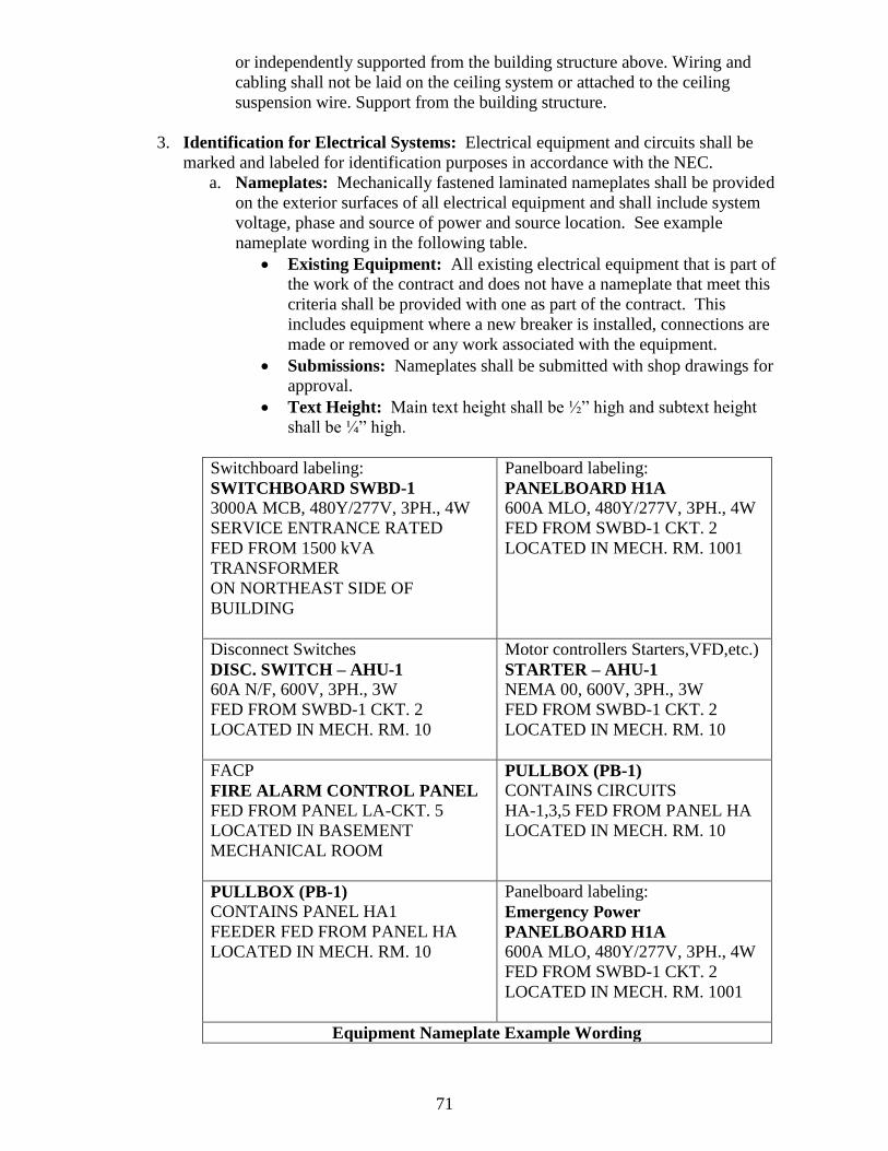
71
or independently supported from the building structure above. Wiring and
cabling shall not be laid on the ceiling system or attached to the ceiling
suspension wire. Support from the building structure.
3. Identification for Electrical Systems: Electrical equipment and circuits shall be
marked and labeled for identification purposes in accordance with the NEC.
a. Nameplates: Mechanically fastened laminated nameplates shall be provided
on the exterior surfaces of all electrical equipment and shall include system
voltage, phase and source of power and source location. See example
nameplate wording in the following table.
Existing Equipment: All existing electrical equipment that is part of
the work of the contract and does not have a nameplate that meet this
criteria shall be provided with one as part of the contract. This
includes equipment where a new breaker is installed, connections are
made or removed or any work associated with the equipment.
Submissions: Nameplates shall be submitted with shop drawings for
approval.
Text Height: Main text height shall be ½” high and subtext height
shall be ¼” high.
Switchboard labeling:
SWITCHBOARD SWBD-1
3000A MCB, 480Y/277V, 3PH., 4W
SERVICE ENTRANCE RATED
FED FROM 1500 kVA
TRANSFORMER
ON NORTHEAST SIDE OF
BUILDING
Panelboard labeling:
PANELBOARD H1A
600A MLO, 480Y/277V, 3PH., 4W
FED FROM SWBD-1 CKT. 2
LOCATED IN MECH. RM. 1001
Disconnect Switches
DISC. SWITCH – AHU-1
60A N/F, 600V, 3PH., 3W
FED FROM SWBD-1 CKT. 2
LOCATED IN MECH. RM. 10
Motor controllers Starters,VFD,etc.)
STARTER – AHU-1
NEMA 00, 600V, 3PH., 3W
FED FROM SWBD-1 CKT. 2
LOCATED IN MECH. RM. 10
FACP
FIRE ALARM CONTROL PANEL
FED FROM PANEL LA-CKT. 5
LOCATED IN BASEMENT
MECHANICAL ROOM
PULLBOX (PB-1)
CONTAINS CIRCUITS
HA-1,3,5 FED FROM PANEL HA
LOCATED IN MECH. RM. 10
PULLBOX (PB-1)
CONTAINS PANEL HA1
FEEDER FED FROM PANEL HA
LOCATED IN MECH. RM. 10
Panelboard labeling:
Emergency Power
PANELBOARD H1A
600A MLO, 480Y/277V, 3PH., 4W
FED FROM SWBD-1 CKT. 2
LOCATED IN MECH. RM. 1001
Equipment Nameplate Example Wording
72
b. Normal Power: Labels for equipment served normal power source shall have
a black background with white lettering.
c. Emergency and Standby Power: Labels for circuits served from a generator
shall have a red background with white lettering and shall contain the word
“Emergency” or Standby” in the description.
d. Junction Boxes and Pull Boxes: Junction and pull boxes shall be labeled
using a black indelible marker indicating power source and circuit.
e. Receptacles and Devices: Receptacles and devices are to have an adhesive
type label on the back of the cover plate.
f. Emergency Light Fixtures: Emergency light fixtures shall be identified by a
red dot/circle on the frame.
4. Phase Color Coding: Conductor color-coding shall match the existing building
convention. If none exists, the phase colors for 120/208V systems shall be red, blue
and black. The phase colors for 277/480V shall be yellow, orange and brown.
5. Demolition
a. Wire: All wire shall be removed back to the last active device, junction box
or panel board. All exposed and/or accessible conduits and boxes shall be
removed.
b. Floor Mounted Devices: Where floor mounted devices are removed the
floor slab shall be ground down and grouted flush.
c. Telecommunication Systems: When telecommunications systems are
replaced, abandoned wire and cabling shall be removed with walls and
ceilings restored to their pre-existing condition.
26 09 00 Instrumentation and Control for Electrical Systems
1. Primary/Secondary Metering: The university has buildings which are primary
metered and others which are secondary metered. Buildings served from the Inner
and Outer Loops are primary metered. All other buildings are secondary metered.
Coordinate all electrical metering requirements with the Associate Director, Utilities
prior to submitting the Basis of Design.
2. Individual Building Metering: Metering shall be installed at each building service
equipment main switchboard. Any building not on the primary loop metering system
and requiring a Dominion power meter shall have the meter installed outside of the
building.
3. Minimum Meter Requirements: Metering shall be digital, with the following
features as a minimum:
a. True RMS metering through the 31st harmonic
b. Real-time readings for current, voltage, real power, reactive power, apparent
power, power factor, frequency, THD and k-factor
c. Demand readings for current, power factor, real power, reactive power and
apparent power
d. Energy readings for real, reactive power
e. BAC NET IP
f. 0.2% accuracy class
g. Alarm/relay functions
h. On-board data logging
73
i. Date/time for each min. /max.
j. Downloadable firmware
4. Building Automation System (BAS) Monitoring: Meter shall have KZY pulse
output tied to building automation system and be setup to accommodate kilowatt-
hours at the Systems Control Center.
5. Meter Accuracy: Accuracy of meters shall be verified and corrected if necessary,
within 10 working days of connection to utilities.
26 20 00 Low-Voltage Electrical Transmission
26 21 00 Low-Voltage Electrical Service Entrance
1. Utility Ownership: The university purchases electric power for its facilities from
Dominion Virginia Power.
a. Primary Feeders: Typically Dominion owns and maintains all primary
feeders and pad mounted transformers
b. Secondary Feeders: The university typically owns the secondary feeders.
2. New Services: New services shall be connected to the Dominion Virginia
distribution system.
a. Minimum Calculations Required: Where new buildings are added to
Dominion’s primary feeders, or a substantial change to an existing structure is
made, submit a calculation at the preliminary submittal showing the existing
load on the feeder, new load and feeder capacity.
26 22 00 Low Voltage Transformers
1. Interior Transformers: Transformers located indoors shall be quiet type unless
they are located in a mechanical room with a high ambient noise level.
a. Dry Type Transformers: Transformers shall be dry-type with the following
characteristics:
Transformers shall meet or exceed the requirements of NEMA TP-1
for energy efficient transformers.
Windings shall be copper
Temperature rise of 115 ºC maximum
HV BIL of 95 kV
A cast primary and either a vacuum pressure impregnated (VPI) or
cast secondary is preferred
AA cooled with at least the provisions for FA cooling.
b. Liquid Filled Transformers: As an alternative, a silicone or other less-
flammable liquid-filled transformer (as defined by NEC 450-23) may be used
indoors. The liquid shall be Factory Mutual approved.
2. Isolation Transformers: K-factor transformers shall be used where large quantities
of harmonic producing loads are present. Associated feeders shall also be sized to
accommodate anticipated harmonic loads.
26 24 00 Switchboards and Panelboards

74
1. Electrical Room Requirement: Building switches and switchgear shall be located
in appropriate electrical rooms.
2. Bussing Requirements: Bussing shall be copper. Separate neutral and equipment
grounding busses shall be provided.
a. Prohibited: Load centers are prohibited.
3. Panelboard Circuit Directories: Directories shall be provided for all electrical
construction involving panel boards and switchboards. Directories shall indicate all
loads, and their locations using final room numbers, served by each breaker. Spares
shall be shall be identified and left in the OFF position.
4. Surge Protective Device Requirements: Provide a Surge Protective Device (SPD)
at the service entrance (as a minimum) for new buildings and major renovations.
a. External Mounted ‘SPD’ Devices: Externally mounted (SPD) devices only
are permitted.
5. One Line Diagrams: A copy of the one line diagram shall be permanently mounted
near the service entrance electrical gear. For renovation projects changes to the one
line diagram shall be added and posted.
6. Panelboard Spare Capacity: All new panel boards shall have spare capacity
(physical and electrical) for future use. Provide a minimum of four 1-inch conduits
with pull wire stubbed out into an accessible ceiling space for new recessed mounted
panel boards.
7. All switchgear shall be bottom fed.
8. Front-venting switchgear shall not be used.
26 27 00 Low-Voltage Distribution Equipment
1. Ground-Fault Circuit-Interrupter Protection for Personnel: In addition to code-
required ground-fault circuit interrupters on main breakers, ground-fault circuit
interrupters shall be used on all sub-main breakers in switchgear, set using selective
coordination to trip prior to the main breaker.
2. Minimum Device Duty: All devices shall be 20A, heavy-duty specification grade
devices (minimum).
3. Prohibited: Residential grade devices are prohibited.
4. Receptacle Installation: All 15 and 20 amp 125 volt general purpose receptacles
shall be mounted with the ground pole in the UP position. Receptacles for dedicated
equipment like refrigerators, dryers and special purpose outlets for other equipment
shall be mounted with the grounding pole in the down position.
a. All stairwells shall have a simplex receptacle 20A-125V mounted at each
landing (not at intermediate landings) for use by housekeeping.

75
5. Wet or Damp Locations: Provided ‘in-use’ type covers for outlets installed in wet
or damp locations.
26 29 00 Low-Voltage Controllers
1. Motors: a. Minimum Motor Efficiency: All motors shall be high-efficiency type, with
a service factor of 1.1 or better and shall meet or exceed the standards set forth
in NEMA standard MG1-1993 revision 1 through 4, Table 12-10.
b. Three Phase Motors: Motors ½ hp and larger shall be 3-phase, using the
highest available appropriate voltage. All such motors shall be equipped with
permanently lubricated bearings.
2. Motor Controllers: All light duty and fractional horsepower motors, except light-
duty fractional horsepower motors, shall be provided with motor controllers.
a. Controller Requirements: Controllers shall provide under-voltage
protection when used with momentary contact control devices and under-
voltage release when used with maintained contact control devices.
3. Phase Monitoring and Protection: All three phase motors shall be provided with
three phase monitoring and shall monitor and protect the motor from damage from
phase loss, phase unbalance, phase reversal and phase sequence.
4. Variable Frequency Drives: All motor variable frequency drives (VFD’s) shall
meet IEEE standard 519. Where multiple VFD’s are fed from the same panel or
MCC, the contractor shall provide a harmonic analysis, at that point, to show
compliance with IEEE 519. Include analysis with drive submittals and provide an
isolation transformer when necessary.
a. Pulse Width Modulation: VFDS shall be pulse width modulated (PWM)
type.
b. Bypass Circuitry: VFDS shall be provided with by-pass isolation switches.
5. Disconnect: A lockable disconnecting means shall be provided at all motor
locations. Disconnects located out of sight from the VFD shall be electrically
interlocked to prevent inadvertent damage.
26 50 00 Lighting
26 51 00 Interior Lighting
1. Occupancy Sensors: Occupancy sensors shall be used in rooms such as restrooms,
single person offices, storage rooms, custodial or janitorial closets, etc. Provide
multi-technology sensors in spaces as recommended by sensor manufacturers. Sensor
layout and coverage shall be shown by the manufacturer during the shop drawing
process and reviewed and approved by the engineer.
a. Conference Rooms and Classrooms: Occupancy sensors shall be used in
conference rooms and classrooms.
2. Multiple Circuits and Switching: Multiple circuits/switching shall be provided in
classrooms and other large rooms to permit reduced power consumption.
76
3. Lighting Fixtures: LED lamps shall be used for lighting. Fluorescent fixtures, when
approved, shall use T-8 or compact fluorescent lamps. Fluorescent lamps shall have a
minimum CRI of 80. Lamp temperatures shall be 3500 ºK unless otherwise directed
by the university PM. All fluorescent ballasts shall be electronic except in areas
where the usage requirements take precedence. Lamps are to be the low-mercury
content, “green tip” type, passing the EPA test for non-hazardous waste.
a. Fixture Selection: The use of 2’ x 2’ light fixtures is required.
4. Exit Signs: Exit signs shall be red LED type with diffused lens and battery back-up.
5. Custom Fixtures: Non-catalog and custom lighting fixtures shall not be used.
6. Service Accessibility: All fixtures shall be mounted so that they can be maintained
safely without specialized equipment or procedures. Fixtures shall be wall mounted
in stairwells so that maintenance can be accomplished with an eight-foot stepladder.
7. Required Lighting Levels: Interior lighting levels shall comply with the
recommended foot-candle levels found in IESNA Lighting Handbook, most current
edition.
a. Mechanical & Electrical Rooms: Lighting levels for mechanical rooms and
electrical rooms shall be 20-30 foot-candles average maintained.
b. Telecommunication Rooms: Lighting level for telecommunications rooms
shall be 50 foot-candles.
c. Corridors: The corridor lighting shall be dimmed or switched off to the
extent that the code required minimum egress and emergency lighting
illumination is always maintained.
d. Stairways: Lighting in stairways shall not be reduced from the design level at
any time by switching or other means.
e. Emergency Lighting: Regardless of emergency power that may be provided
by local generators, emergency lighting fixtures shall be provided with
integral battery ballasts in addition to another stand-by emergency power
source when available.
f. Mechanical; Electrical & Telecommunication Rooms: Mechanical,
electrical and IT room lights shall have an emergency battery pack and shall
be circuited to an emergency power circuit when available.
g. Task Lighting: The use of user provided task lighting is to be encouraged
and maximized. The illuminance ratio for maximum to minimum light levels
shall not exceed 10:1 in any occupied space.
h. Equipment Illumination: For safety reasons light fixtures will be located at
or around equipment so that maintenance personnel will not obscure the
required illumination.
i. Fixture Support: Recessed light fixtures are to be suspended from the
structure. Do not support solely from the ceiling suspension system.
j. Emergency Illumination: Emergency illumination shall be provided by light
fixtures which contain an integral battery ballast or fixtures that are connected
to an emergency power system. Emergency only light fixtures (unit type /
emergency backup unit equipment) shall not be used on campus.
26 56 00 Exterior Lighting
1. Required Illumination:
77
a. Means of Egress Illumination:
Public Way Definition: For the purpose of site lighting as required
under this manual, the Public Way is defined as the nearest street or
campus sidewalk.
2. General Campus Lighting: General campus lighting outside of the “Means of
Egress Illumination” defined above shall comply with the following Illumination
levels:
Exterior Illumination Requirements – Horizontal (Measured at Grade)
Location/Area Foot-candle levels Remarks
Paths, Walks and Ramps 0.5 avg. & 0.125 min. 4:1 avg./min.
Exterior Steps 0.2 min. top to bottom 4:1 avg./min.
Roadways Per IES Recommendations
Parking Lots & Garages Per IES Recommendations
Exit Discharge (Normal) Per VUSBC/IBC
Exit Discharge (Emergency) Per VUSBC/IBC
3. Fixture Type: All new exterior lighting fixtures shall be university approved cut-off
type, designed to meet Illumination Engineering Society (IES) standards for cut-off
optics, unless otherwise directed.
a. Lamp Type: LED luminaires
b. Foot Candles: All foot-candle references are average maintained values,
unless otherwise noted.
4. Pole Mounted Fixtures: a. Material and Finish: Except for the Historic Campus, poles and fixtures
shall be cast aluminum with standard bronze finish to match existing. Poles
and fixtures are provided and installed by the contractor.
b. Manufacturer and Model: Except for the Historic Campus , the only
acceptable pole and fixture for campus wide use are as follows:
Luminaire: Holophane Arlington LED (ARE) Series Catalog #ARE-
100-5K-AS-A3-Z-S; 100 Watt System, 5000 Series CCT, Auto-
Sensing Voltage (120-277), 50/60 Hz, Asymmetric Acrylic Refractor,
Bronze, Spike .
Pole: Holophane Barrington Aluminum Pole (BRA): Catalog #BRA-
12-OTN-20-PRC-ABG-BZ, twelve feet, octagonal tapered (Cast)
0.375 wall, 20 inch base, 7 inch Post Capital, Anchor bolts, galvanized
steel, powder coat paint finish, bronze.
Lamp: Shall be LED type.
c. Historic Campus: Poles and fixtures for the Historic Campus shall be
provided by the university and installed by the contractor.
5. Installation Requirements: a. Recessed Lights: Recessed lights shall not be used in masonry walls or
stairs.
b. Lighting Control: Site lighting shall be photocell controlled in logical
groups with hand-off-automatic switch at contactor.
78
c. Circuiting: Site lighting fixtures are to be powered with underground direct
buried copper wiring, insulation colored according to voltage; 120/208V –
Black, red, blue; 277/480V- brown, orange, yellow.
d. Pole Numbering: All pole and post-mounted lighting fixtures shall be
numbered on the construction documents and on the erected fixture. Obtain
fixture ID number and label size/style from Director of Operations and
Maintenance.
e. Record Documents: “As-built” or record documents plans for outdoor
lighting shall provide a Utilities Lighting Chart with fields designating the
following:
Light fixture ID number (from Utilities)
Lamp type (adequate for ordering lamps)
Fixture Manufacturer and catalog/model number including all
accessories.
Electrical feed (building name and number, and panel designation)
Watts (lamp and fixture wattage)
Voltage
Pole height
Pole Manufacturer and catalog/model number including all
accessories.

79
27 00 00 Communications
27 05 00 Common Work Results for Communications
1. Cabling: All cabling run above the ceiling shall be plenum rated.
a. In-Building Emergency Communications Coverage: All new and
renovated buildings shall be provided with an in-building emergency
communications system complying with the current adopted VCC.
b. Riser Diagram: Provide a riser diagram of the system on the documents
showing all interface points with other systems.
c. Infrastructure: The A/E shall coordinate system requirements with the
owner selected vendor to provide a system of conduits, etc. to support the
installation of cabling and equipment by others.
2. Cable Television: Cable television services shall be provided in university
residential facilities and other buildings. The cable television system is owned and
operated by the university.
a. Cable Connections: The cable connection is obtained from the university
owned system and coordinated through the university PM.
b. Conduit System: Provide a system of conduits, outlet boxes, backboards,
etc. to support the installation of cabling by others.
c. Provide a riser diagram of the system on the documents showing all interface
points with other systems.
3. Other Communication Systems: Other special systems such as black board system
for vending, intercom, audio or paging shall be provided on a project-by-project
basis.
a. Provide a riser diagram of the system on the documents showing all interface
points with other systems.
80
28 00 00 Electronic Safety and Security
28 10 00 Electronic Access Control and Intrusion Detection
1. Building Entrances: All building entrances for any new building, addition or major
renovation shall have conduit, electrical boxes, and a power source to accommodate
an electronic access system.
a. The design shall include requirements for the contractor to insure coordination
of operation of the access system with any power operated doors and with the
fire alarm system.
2. Other Building Locations: Installation of access control systems in other areas of
the building (laboratories, vivaria, valuable collections, cash management areas, etc.)
shall be considered on a project-by project basis.
3. Monitoring: Security alarm systems are monitored at either the university Police
Station on Ukrop Way or by an off-site vendor.
28 20 00 Electronic Surveillance
28 23 00 Video Surveillance
1. Minimum Requirements: At a minimum, provide a system of conduits, outlet
boxes, backboards, etc. to support the installation of a security system by others.
28 30 00 Electronic Detection and Alarm
28 31 00 Fire Detection and Alarm
1. Sole Source Simplex Fire Alarm and Detection System: The university has
standardized campus wide on a Simplex fire detection and alarm system.
2. Reporting to Campus Police Station: All new and replacement fire alarm systems
shall report to the main panel at the university Police Station. The connection is net
based and complete two-way communication is required for all alarms, trouble
conditions, and tolling of the system.
3. New Devices added to Existing Systems: Where new devices will be added to an
existing system, they shall match the types of, or be compatible with, the existing
system. Devices added to an existing system shall be able to communicate with the
existing system regardless of manufacturer.
4. Panel Height: Height of Fire Alarm Control Panel and annunciator LED/LCD
readout/ display will be at 60 inches above finished floor.
5. Hold Open Devices: Door hold open devices shall be provided on all high traffic,
public doors where there is not an established occupant. For sleeping room doors
(and individual office doors), provide closure devices but no hold open device.
81
6. Voice Alarm Message: All voice alarm system messages shall use the following
pre-approved verbiage and voice:
a. Evacuation Message Wording:
10 seconds – or current whoops) followed by;
(pre-recorded phrase 161 – 3 times) “Attention, Attention,
Attention” followed by;
(pre-recorded phrase 163) “An emergency has been reported” followed
by
(pre-recorded phrase 171) “You are to leave the building by the
nearest exit or stairway”
b. Total Evacuation Sounds will be:
Whoops, message including “Attention ……Stairway”,
No whoops
Repeat message
(no whoops)
Repeat message
Then whoops continually until silenced.
c. Voice: Female.
7. Conduit Systems: All wiring for new and replacement fire alarm systems, including
detection devices, shall be installed in conduit.
8. Conduit Requirement: All wiring for fire alarm systems shall be installed in
conduit except for renovation projects where the existing wiring is not run in conduit.
9. Notification and Annunciation Circuit Classification: All new and upgraded fire
alarm system notification and annunciation circuits shall be class ‘A’ or class ‘B’
depending upon the following criteria.
a. Class ‘A’ circuits shall be provided for dormitories, large buildings, buildings
with regular late night hours
b. Class ‘B’ circuits shall be provided for all other facilities.
10. Class ‘A’ Circuits: The following provisions and sketch SKF-1 apply only to those
fire alarm systems which require class ‘A’ circuits. Additionally the circuits
addressed by these provisions apply only to circuits for supervising the status of
devices like fire pumps, kitchen hoods, tamper, pressure and flow switches, and
similar devices. This provision does not apply to automatic detection device circuits
which monitor devices like heat and smoke detectors.
a. Devices Requiring Fire Alarm Supervision: Devices requiring supervision
by the fire alarm control unit but which are not provided by Simplex (fire
pump contact points, kitchen hood monitoring points, tamper and flow
switches and similar devices) shall be monitored with Simplex Addressable
Monitor Modules as described below.
Individual Point Monitoring: Each monitored point shall be
monitored individually; i.e. one tamper switch is one monitored point,
one flow switch is one monitored point. For ease of maintenance and
troubleshooting, multiple devices on one supervision circuit are not
permitted.
82
b. Class ‘A’ Circuits Required by university Technical Standards: For fire
alarm systems requiring class ‘A’ circuits as determined by William and Mary
Technical standards, utilization of the standard Simplex 4090-9001 Addressable
Monitor Modules using a Class ‘A’ circuit for the addressable SLC, Idnet
Channel and Class ‘B’ circuit to the monitored device is permitted as long as the
monitored device is within 10’ of the 4090-9001 addressable module. If the
monitored device is greater than 10' from the addressable module, then a 4090-
9106 type module and Class ‘A’ circuit is required.
11. Abbreviations:
EOL – End of Line (Resistor) IM – Individual Addressable Module
FACP – Fire Alarm Control Panel SLC – Signaling Line Circuit
IDC – Initiating Device Circuit ZAM – Zone Adapter Module
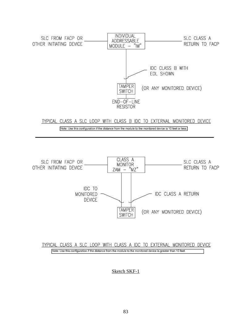
83
Sketch SKF-1

84
12. Smoke Detection Requirements: In all new construction and all major renovations,
smoke detectors shall be installed in rooms set up for sleeping and associated egress
pathways from sleeping rooms.
13. Elevator, Sprinkler and Fire Alarm Coordination: Heat detectors shall be used to
shut down elevator power.
28 34 00 Fuel-Oil Detection and Alarm
1. The leak detection system shall be UL listed for the liquid it is intended to detect and
shall be monitored by the Building Automation System (BAS).
a. Auxiliary Contacts: Provide auxiliary contacts as necessary to allow the
BAS to monitor status, trouble and alarms.
85
31 00 00 Earthwork
31 05 00 Common Work Results for Earthwork
1. Land Disturbance: When required, submit an Erosion and Sediment Control
Application with supporting documents in accordance with the current W&M Annual
Standards and Specifications for Erosion and Sediment Control.
2. Suitable Topsoil: Material as defined by the project geotechnical report. In the
absence of a project geotechnical report, topsoil that is free from refuse or any
material toxic to plant growth and reasonably free from subsoil, stumps, roots, brush,
stones, clay lumps or similar objects larger than 3 inches in their greatest dimension
salvaged from excavation shall be stockpiled in a location designated by the
university for reuse in the project.
3. Suitable Fill and Backfill: Material as defined by project geotechnical report.
4. Surplus Materials: Clean fill, other than that used for backfilling, may be disposed
of on the grounds within the boundaries of the project site. All other surplus material
(excavated material and construction debris) shall be disposed of by the contractor
off-site legally.
5. Hazardous Materials: Specifications shall state that in the event hazardous
materials are encountered in site work, work shall be stopped immediately and the
university PM promptly notified.
31 10 00 Site Clearing
1. Refuse Disposal: All logs, stumps, brush, wood, and refuse shall be disposed of off
the university grounds in an approved landfill. Consideration will be given to
Contractor mulching logs, brush, and wood for use on campus where appropriate.
On-site burning is prohibited.
2. Plant Protection: Trees, within the Construction Contract Limit Lines are to be
protected with rigid fencing (wood or chain link) at or beyond the drip line to prevent
damage by equipment and external construction activities. The selection of trees,
shrubs, and planting beds within the limits of construction to be protected shall be
coordinated through the Associate Director of Grounds and Gardens.
3. University Maintenance: Access to specific planting areas that need regular
maintenance by university personnel shall be provided through the construction site.
4. Soil Injections: Tree root systems, which are likely to be negatively impacted by
construction activities as identified in advance by the university Arborist, shall
require a slow release liquid fertilizer injection throughout the entire root zone before
and after the construction activities. Trees transplanted from the project require the
same injections.
a. Trees not identified in advance for soil injection, but are believed to have
sustained root system damage as determined by the university arborist, shall
receive root injection after construction activities are completed.

86
31 23 00 Excavation and Fill
1. Trenching, Excavation and Backfill for Utility Installation:
a. Exploratory Excavation: Where underground project work is in close
proximity to existing buried utilities or other existing underground
improvements, the contractor will cautiously execute exploratory
excavation(s) to verify exact horizontal and vertical positions of existing
systems. Exploratory excavation findings, in order to avoid conflict and
maintain required separations and clearances may result in design adjustments
to existing and/or proposed improvements
31 31 00 Soil Treatment
1. Termite/Insect Treatment: A licensed professional shall treat all new
excavations for termite and insect infestation. Specify under slabs, along
foundation walls, around all openings and protrusions in slabs on grade.
87
32 00 00 Exterior Improvements
32 05 00 Common Work Results for Exterior Improvements
1. Minimum Elevation: The 100-year flood elevation shall be as depicted on the latest
edition of the Flood Insurance Rate Maps, prepared by the Federal Emergency
Management Agency. The minimum finished floor elevation and
mechanical/electrical equipment pads must be at least 1foot above the 100 year flood
elevation. The 100 year flood elevation shall be noted on the project documents.
2. Design Standards: Storm drainage design and associated construction must be in
accordance with the guidance noted herein and the Virginia Stormwater Management
Handbook, latest edition.
3. Surface Storm Drainage: Grade the site to provide positive drainage away from the
facility. Establish finished floor elevations at least 6 inches above finished grade at
the perimeter of the building. Use spot elevations to establish positive drainage away
from buildings and toward stormwater drainage structures. Ensure that the grading
and associated stormwater runoff during construction and at completion of the project
does not adversely affect surrounding sites.
32 12 00 Flexible Paving:
Unless modified by documented site conditions and geotechnical recommendations,
flexible light duty pavement shall be designed and installed in accordance with the
Geotechnical Engineering Report or as follows:
1. Surface: Asphalt Concrete, VDOT SM-9.0 A
2. Base: Asphalt Concrete, VDOT BM-25.0
3. Sub-base: Untreated Aggregate, VDOT 21A, Type II Compact to 95% Relative
Density, ASTM D-698 (Standard Proctor)
4. Placement and Compaction: All asphalt pavements shall be placed and compacted
in accordance with VDOT Road and Bridge Specifications.
32 13 00 Rigid Paving
1. Dumpster Pads: Reinforced concrete pavement pads are to be constructed for all
dumpster locations. Sizes must accommodate the front wheel of the garbage truck
when engaged in the collection process. Dumpster pads shall be designed and
installed in accordance with the Geotechnical Engineering Report.
32 16 00 Curbs, Gutters, Sidewalks and Driveways
1. Curbs and Gutters: Curbs and gutters shall comply with Virginia Department of
Transportation Road and Bridge Standards, latest edition. Care must be taken to
match existing curb and gutter on campus and within the City of Williamsburg..
88
a. Projects located within the areas of campus designated as “Old” and
“Historic,” new curbs and gutters shall be designed and constructed with
materials to match existing aesthetics of nearby finishes.
2. Sidewalks – General Requirements: The minimum sidewalk width shall be 6’-0”.
a. Fire Truck Use: Sidewalks intended to be used for fire truck access shall be
designed and installed in accordance with the Virginia Fire Prevention Code
and the project Geotechnical Engineering Report.
b. Separation from Curb: Pedestrian sidewalks shall be separated from
curbing by a minimum 2 foot wide buffer strip measured from the back of the
curb to the edge of the sidewalk.
3. Concrete Sidewalks: Sidewalks shall be a minimum 5” thick cast in place concrete
installed over 6" compacted aggregate base and compacted sub-grade in accordance
with the project Geotechnical Engineering Report.
a. Finish: Walks to be broom finished perpendicular to the direction of traffic
flow.
b. Expansion Joints: Provide expansion joints where sidewalks abut existing
structures and at a maximum of 30’-0” on-center along the length of the
sidewalk.
Construction: Joint material shall be set ½-inch below the surface
and the joint shall be filled with self-leveling traffic rated sealant.
Joint material must not project above the surface of the sidewalk.
c. Control Joints: The slab between expansion joints shall be spaced equal to
the width of the sidewalk at a depth equal to one-quarter of the thickness.
d. Formed Construction: Formed construction joints shall be provided at the
end of each placement.
e. Underdrains: Sidewalk underdrains shall be installed in accordance with
VDOT Road and Bridge Standards, latest edition.
4. Concrete Driveways: Construct in accordance with “Concrete Sidewalks” above.
5. Brick Sidewalks: Brick sidewalks shall be constructed on top of a concrete slab.
The slab shall extend under the soldier course.
a. Slab Construction: See requirements for concrete sidewalks above.
6. Exterior Steps and Hand Rails: All exterior stairs shall be illuminated and shall
have handrails on both sides regardless of the number of risers.
a. Handrails:
Spacing and Location: Where handrails would exceed 5’-0” center-
to-center, an intermediate handrail is required. For monumental stairs,
whether required fire egress exit ways or not, handrails shall be located
along the most direct path.
Posts: Where post-mounted hand railing supports occur, careful
consideration shall be given to the embedment of posts to minimize
deterioration of the posts and/or the concrete slab or system into which
it penetrates. Whenever this embedment occurs in a pre-cast concrete
system specifications shall be explicit regarding galvanization of the
embedded sleeve and any anchors (as a unit after any welding) prior to
being placed in the form work.

89
32 17 00 Paving Specialties
1. Pavement Markings: Painted striped crosswalks shall be provided at all road
intersections.
2. Bicycle Lanes: New or improved roads of sufficient width shall include bicycle
lanes on both sides of the street. Demarcation of the bicycle lanes through striping
and signage shall be consistent with established Virginia Department of
Transportation standards.
32 30 00 Site Improvements
32 39 00 Manufactured Site Specialties
1. Bollards: Two types of bollards are approved for use at the university.
a. Metal Bollard: These bollards shall be ductile steel in construction, 6 foot
in length, concrete filled and concreted in the ground at least 3 feet in depth.
Decorative bollards will be painted Sherwin Williams Industrial Enamel
Bronze tone. Caution bollards will be painted in traffic yellow for visibility.
b. Wooden Bollard: The wooden bollard shall be used where appropriate on
the Historic Campus. Wooden bollards shall be painted to match Sherwin
Williams Woodscapes Bronze tone flat finish.
2. Signs: New buildings and major building renovations shall provide permanent
exterior signage in compliance with the established university standards.
a. Construction Signs: when approved, shall be limited to a maximum 4’-0” x
6’-0” sign erected at the contractor’s expense. See the DCM for sign
requirements.
3. Bicycle Racks: The design of all university facilities, or major site renovations, shall
include adequate bicycle storage with permanently installed racks. Bicycle racks
shall be the 9 bike wave (serpentine) style racks and may be mounted with an above-
ground flange or in ground as appropriate for each location.
4. Emergency Telephones: New buildings, new parking lots and major site work
projects shall provide the location(s) for emergency telephone(s) that are handicapped
accessible and located on or near lighted walkways providing visibility and comfort
in their use. The Campus standard emergency phone is manufactured by Code Blue.
a. Supporting Utilities: All utilities (power and telephone lines) and the
foundation for the fixtures shall be installed under the project. Provide a
foundation and mounting detail in the construction documents.
b. Owner Provided Fixtures: Facilities Management Operations and
Maintenance will procure and install the fixtures.
Specifications shall state the requirements of the contractor. Facilities
Management will be fully responsible for installation including
necessary wiring and telephone cabling to a university point of
connection.
c. Emergency Power: Power for emergency telephones is to be an emergency
circuit where available. The conduit system shall have no access points

90
between E-Phone locations. The handholes that are part of the E-Phone shall
be used to make required connections and routing of conductors.
5. Benches: Benches will be university furnished and installed. Benches approved for
use at the university are:
a. Manufacturers and Models:
b. Country Casual, “Monarch” #4613
c. Kingsley Bate, “Hyde Park” #HP60
d. Gardenside, “Parkside” #2606
6. Trash Receptacles: Trash and ash urn receptacles will be university furnished and
installed.
a. Manufacturer and Model: The trash receptacles will be United Receptacle
– Americana Series, color – architectural bronze, model number UN-MI36.
32 80 00 Irrigation
1. Irrigation systems are shall not be provided for new and renovated buildings. When
irrigation systems are approved, water shall be supplied from wells or by recycling
from underground storage tanks.
32 90 00 Planting
1. Planting: The selection of plant material and the planting and maintenance of trees,
shrubs and herbaceous plants must be consistent with the current AAN American
Standard for Nursery Stock.
a. Approved Landscape Plans: Planting shall be in compliance with an
approved landscape plan.
b. Plant Selection: Prior to planting, all plant material must be approved by the
Facilities Management Landscape Area Supervisor as healthy specimens of
the specified planting.
c. Planting Procedures: The width of each planting hole shall be three times
the size of the root ball. The depth of the hole shall be 2’’ less than the
distance from the bottom of the root ball to the root collar. The bottom and
sides of the each hole should be scarified to encourage root development.
Any soil or mulch covering the root collar shall be removed.
Watering: All Plant root balls shall be saturated with water at time of
planting.
d. Tree Planting: To preserve the assets of trees and manage the assets of
underground utilities, new trees shall not be planted:
Within ten feet of any existing underground utility lines with joints
Within five feet of any existing underground utility lines without joints
(joints may occur when they are at least ten feet from the tree center in
both directions).
91
Where new storm and or sanitary sewer piping alignment cannot be
avoided within ten feet of an existing or new tree, use HDPE butt-
welded pressure piping.
e. Soil Injections: Newly planted trees shall receive soil injections to promote
root growth.
f. Soil Preparation: Soils in areas to be planted that are compacted above 85%
maximum density shall be mechanically loosened to a minimum uniform
depth of 24” below final grade.
Planting holes shall be excavated one day prior to planting and tested
for soil porosity. Holes left open overnight should be roped off for
public safety.
Soil conditions, which are inadequate for sustaining the growth and
development of plants, must be reported to the Facilities Management
Landscape Area Supervisor and/or the Associate Director of Gardens
and Grounds. Inadequate soil conditions must be addressed prior to
planting.
g. Planting Warranty Period: Plantings shall be covered by a warranty period
of one year.
92
33 00 00 Utilities
33 05 00 Common Work Results for Utilities
1. Tree & Plant Protection: Underground utilities shall be located so that construction
will not damage or destroy the plants to remain. Utility trenching shall not be located
closer than 1’-0” for each 1” in diameter, with a minimum of 5’-0” and a maximum
of 20’-0” for trees to remain. Trenching near heritage trees and mature specimens
shall be outside of the drip line of the tree.
2. Utility Identification: All underground pipe, including pipe under a building, shall
be installed with trace wire taped to the top center of the pipe for future identification.
The trace wire shall be extended to inline hand holes, valve boxes, appurtenant
structures or manholes for easy accessibility. A secondary marker of nonmagnetic
color coded warning tape shall be installed above each pipe, approximately 12” below
finished grade.
3. Tunnels: All heating water, steam, and condensate mains shall be run in tunnels.
Tunnels shall be 5’ x 6’ if pipes are run only on one side or 6’ x 6’ if pipes are run on
both sides. Tunnel structure shall be designed for HS 20 traffic. Hot water branches to
individual buildings may be direct buried provided piping systems are pre-
manufactured double wall piping systems.
4. Utility Sources: All utilities to a proposed building site are to be supplied from
university central distribution systems, unless the required capacity is unavailable and
cannot be cost-effectively added to the system. Utilities not available from a central
system shall be generated at the proposed building.
a. Capacity: New hot and chilled water generating and distribution systems
shall be provided with firm standby capacity in the form of N+1, where N
represents the quantity of equipment required to generate or distribute the
required hot or chilled water under full load conditions.
b. Control: Pumping systems shall be provided with a simple lead/standby
arrangement. A determination and findings report may be used to justify a
lead/lag/standby arrangement, but such an arrangement shall not be used
without prior consent by the university.
c. Fuel Source: Unless a life cycle cost analysis, provided with the basis of
design justifies a firm gas system, new boilers shall be provided with dual fuel
boilers capable of burning both natural gas and number 2 fuel oil. Fuel oil
storage capacity shall be sized to provide a minimum of 4 days operation at
full fire. This may require a separate meter for cooking and water heating,
should these systems use natural gas.
33 10 00 Water Utilities
1. Pipe Mains: Pipe mains shall be a minimum of 6" in diameter.
2. Minimum Ground Cover Required: a. Water Mains – 36”
b. Water Service: - 24”
c. Fire Service: - 36"
93
3. Pipe Material: Underground water distribution pipe shall be asphalt coated, cement
lined ductile iron, Class 52 or higher, with flexible restrained joints.
a. Water lines 2 ½” nominal diameter and smaller shall be copper type "K”
4. Corporation Stops: Corporation stops shall be installed while the main is under
pressure and at a 45-degree angle to the horizontal plane.
5. Entry Point into Buildings: The entry point into buildings shall be with factory
flanged ductile iron, Class 53 or higher.
6. Fire Service: Water lines used for fire service shall extend from the water main and
be brought into each building independently from the potable water service
a. Post Indicator Valve: A post indicator valve (PIV) shall be provided for
each building.
33 12 00 Water Utility Distribution Equipment
1. Water Meters:
a. Where Required: Water meters shall be installed to meter each building and
irrigation system independently. The meters can be located within mechanical
rooms or within freeze resistant valve vaults immediately adjacent to the
building or well they serve.
Deductive Sub-metering: Provide separate deductive sub-metering
for make-up water to Boiler, chiller and cooling tower systems.
b. Isolation and Bypass: Meters shall be installed with isolation valves
upstream and downstream for isolation purposes. A bypass that can
accommodate full flow conditions shall be provided around all water meters
and pressure reducing valves.
c. Strainer: A strainer shall be installed upstream of the meter.
d. Meter Type: Meters used for potable water shall be electromagnetic or
ultrasonic transit time, all others shall be turbine type or ultrasonic transit
time.
e. Compound Meters: Meters for largely varying flows such as dormitories,
shall be compound type meters and all others shall be turbine type, each being
revenue grade, having a maximum inaccuracy of 1% of rate and span.
f. Construction: Meters shall be constructed of brass or bronze.
Accuracy: All meters shall be revenue grade, having a maximum
error of 1% of rate and span.
Cumulative and Max/Min Capabilities: Meters shall be capable of
showing cumulative gallons used, and of measuring the anticipated
maximum and minimum flow rates.
Auxiliary Contacts: Meters shall be provided with a set of contacts
to allow communication with the Building Automation System.
g. Fire Protection Service: Fire protection service shall be through a separate,
unmetered service.
33 13 00 Disinfecting of Water Utility Distribution
1. General: New, relocated, and modified water mains and accessories shall be
disinfected prior to tie-ins in accordance with AWWA C651.

94
2. Repeat Testing: If the initial disinfection fails to yield satisfactory samples,
disinfection shall be repeated until satisfactory samples have been obtained.
33 20 00 Wells
1. Back Flow Protection: New wells or wells effected by the project work shall be
protected by an approved backflow prevention device.
a. Multiple Buildings: Multiple buildings served by wells shall have a
backflow prevention device installed at the point of water entry to each
building. These backflow devices shall be in addition to the backflow device
serving the well.
33 30 00 Sanitary Sewerage Utilities
1. Comply with standards and regulations of the Virginia Department of Health VDH
(12 VAC 5-610) and the Department of Environmental Quality DEQ (9 VAC 25-
790).
33 31 00 Sanitary Utility Sewerage Piping
1. Minimum Pipe Size:
a. Lateral: 4’’ Minimum Diameter, line from building to Collector.
b. Collector: 8” Minimum Diameter, sewer line between Manholes.
2. Minimum Ground Cover Required: 36”
a. Sewer piping shall not be located within areas of flooding or drainage
channels.
3. Crossing Potable Water Lines: Sewers shall cross under water lines to provide a
separation of 18 inches between the top of the sewer and the bottom of the water line.
When local conditions prohibit this vertical separation, the sewer shall be constructed
of cement lined ductile iron pipe using joint restraints and satisfy the requirements of
Virginia Sewage Handling and Disposal Regulations (12VAC-5-610).
4. Pipe Materials: Pipe shall be push on joint Extra-heavy cast iron (CI), Class 50
ductile iron (DI), or SDR-26 PVC for gravity sewer. HDPE pressure pipe or solvent
welded PVC, Schedule 40 shall be used for force mains.
5. Minimum Slope: Sewers shall be designed and constructed to give mean velocities,
when flowing full of not less than 2.0 feet per second, based on Manning’s formula
using an “n” value of 0.013. Sewer piping on a 20% slope or greater shall be
secured with concrete anchors.
6. Sanitary Service Lateral Connection: Laterals shall follow direct alignment from
building to collector.
33 39 00 Sanitary Utility Sewerage Structures
1. Where Required:
95
a. Manholes: Provide a sanitary sewer manhole adjacent to all buildings to
which laterals from building are directly connected. Install manholes at the
end of each collector, at all changes in slope, size or alignment; at all
intersections and at distances not greater than 300 feet.
2. Construction: a. Sanitary Manholes and Manhole Frames and Covers: Manhole frame and
cover shall meet VDOT MH-1 standards..
b. Pipe Penetrations: A secure bond between the pipe and manhole wall shall
be obtained. Flexible insert gaskets shall be used to obtain a watertight joint.
At existing manholes install a sleeve for connection. Use flexible
rings, mechanical clamps, grout and water stop for a leak-proof
connection.
c. Precast Wall Sections: Shall be seated with flexible joint sealant for their
full circumference. Lift holes, defects, joints between sections and frames and
covers shall be sealed with nonshrink waterproof grout.
Precast manhole joints (inside and outside) shall be filled with non-
shrink grout and finished smooth.
d. Coatings: Manholes shall be coated from inside with vapor/moisture
penetration preventing epoxy coating, and from the outside with bitumastic
/coal tar based waterproof coating.
3. Minimum Size: Manholes shall have a minimum 48” inside diameter with invert
shaping.
4. Drop Piping: Manholes with an invert change of 18” or two times the inlet pipe
inside diameter, whichever is greater, shall be provided with drop piping outside the
manhole.
5. Watertightness: Manhole to receive a factory applied epoxy coating. Sections and
grade adjustment rings to be set in butyl joint material. Manhole lift holes and joints
shall be sealed with non-shrinking hydraulic cement grout with exposed interior
surfaces sealed with epoxy field applied after grouting. Inlet and outlet pipes shall be
joined to the manhole with a flexible boot type watertight connection that allows
differential settlement of the pipe and manhole wall to take place.
33 40 00 Storm Drainage Utilities
1. Design Standards: Storm drainage design and associated construction must be in
accordance with the Virginia Stormwater Management Handbook, latest edition.
a. Inlets: Inlets in paved areas shall be designed to accommodate a Rainfall
Intensity of 4 inches per hour with ponding depth not to exceed 4 inches.
b. Storm Sewer Conveyance Systems: Storm sewer conveyance systems shall
be designed to accommodate the rainfall frequency for the 10 year event using
the Rational or Modified Rational Method.
c. Runoff Calculations: Runoff, Hydrologic Routing through impoundments,
and natural and constructed channels shall use calculation methods based
upon NRCS/SCS 24 Hour Rainfall, Type II synthetic hydrographs for the 1,2,
10, 25 and 100 year events based SCS TR-20.
33 41 00 Storm Utility Drainage Piping
96
1. Building Roof Drainage: All building roof drainage, including external downspouts,
areaway drains, and foundation drains shall be connected to the storm drainage
system. Connections shall preferably be made to a manhole or a drop inlet directly.
Where the preferred connection is not feasible or economically justified, the
connection shall be to the storm sewer with a “Y” a maximum of 50-feet away from
the building. Provide cleanout at each change in direction of any drainage piping.
2. Foundation and Retaining Wall Drainage: Perforated polyvinyl chloride pipe
surrounded by #57 stone wrapped in geotextile fabric shall be used for all foundation
and retaining wall drainage systems. Class III reinforced concrete pipe, minimum 15”
size per ASTM C 76, shall be used for all infrastructure systems. HDPE pressure or
HDPE double wall corrugated pipe may be used for mains under 24”.
3. Laterals: Polyvinyl chloride (PVC) Schedule 40, solvent welded piping is permitted;
for yard drains, 8” minimum through 12” maximum; for roof, area drains, and
foundation drains, 4” to 6” as required for single drain lateral; and 8” to 12”
maximum for multiple drain collector lateral.
4. Minimum Cover: Minimum cover on pipe shall be 24”. Slope of piping shall result
in self-cleaning velocity (2-fps minimum) for the diameter of piping used. Storm
sewer piping on a 20% or greater slope shall be secured with concrete anchors.
33 42 00 Culverts
1. All drainage culverts or conveyance systems shall terminate with either an end wall
or end section where culverts and storm drains daylight.
33 44 00 Storm Utility Water Drains
1. Grit/Oil Separation: Provide grit and oil separation conforming to Virginia
Department of Conservation and Recreation (DCR), Minimum Standard 3.15 at
vehicle storage, parking and fueling facilities to prevent contamination of surface
waters.
33 45 00 Storm Utility Drainage Pumps
1. Prohibited: Storm utility pumps shall not be used.

97
33 49 00 Storm Drainage Structures
1. Area Drains: Exterior drains located in patios, window wells, exterior stairs and
other locations that could potentially back up and damage a building if they become
plugged with leaves and debris shall have a minimum surface drain area of 144
square inches.
a. Secondary Drains: All area drains shall be provided with a secondary drain
to minimize the possibility of water entering a building.
2. Manholes a. Where Required: Manholes shall be required at any change of direction for
main storm sewer piping and at intervals not exceeding 400-feet in a straight
run.
b. Minimum Size: Manholes shall have a minimum 48” inside diameter with
shaped flow troughs at bottom. Manhole frame and cover shall meet VDOT
MH-1 standards.
c. Joints: Patch precast manhole joints with non-shrink grout inside and
outside. Apply bitumastic/coal tar waterproof coating from outside.
d. Pipe Connections: Pipe connections to new manholes and inlets shall be
with flexible rubber boots. At existing structure install sleeve prior to
connection using flexible rubber boot.
3. Inlets and Catch Basins a. Where Required: Curb inlets shall be used for all surface drainage for
roadways and parking lots.
b. Drop Inlets:
Minimum Size: Minimum inside size for drop inlets shall be 24” with
up to 18” pipe diameter and 4-feet maximum depth. Minimum inside
size of drop inlet shall be 48” for pipe size larger than 18” pipe
diameter or greater than 4-feet depth.
Grates: Inlet grates shall be bicycle-safe and oriented with the long
axis of the openings perpendicular to the direction of bicycle traffic.
The tops of all structures shall be flush with the pavement surface.
Traffic Rating: Inlet structure grating shall be heavy-duty traffic
rated (HS-20), providing a minimum 24” clear opening for access.
c. Yard Inlets:
Grates: All grates for yard inlets shall meet handicapped accessibility
standards and shall be close mesh for pedestrian traffic to include
narrow heels. Grate inlets shall be used for all lawn areas.
Pipe and Fittings: Area drains and yard drains installed with
minimum pipe size and cover shall use shallow cast iron fittings or
heavy-duty HS 20 traffic rated PVC/HDPE fittings.
d. VDOT Standard Structures: Virginia Department of Transportation
(VDOT) standard structures are to be used.
33 60 00 Hydronic and Steam Energy Utilities
33 61 00 Hydronic Energy Distribution
1. Pipe Materials:

98
a. Hot Water Pipe: Pre-insulated double wall piping system
Carrier Pipe: Standard Weight
Insulation: Closed cell polyurethane
Jacketing Material: Steel with fusion bonded epoxy coating
b. Chilled Water Pipe: Pre-insulated double wall piping system similar to hot
water piping, or single wall piping system below:
4” and Larger: pipe shall be asphalt coated, cement lined ductile
iron, Class 52 or higher, with flexible restrained joints.
Entry point into buildings shall be with factory flanged ductile iron,
Class 53 or higher.
Smaller than 4”: Water lines shall be copper type "K".
2. Valves and Valve Vaults: Valves and valve vaults shall be required at each
piping intersection to allow each individual branch to be isolated for service.
a. Confined Access: Valve vaults shall conform to V requirements for confined
access. Piping, valves, ladders and access points shall all be arrange to allow
service to occur without crossing over/under obstructions that might hinder a
rescue effort. Valve vaults shall have two manways or be vented.
b. Damp Proofing/Water Proofing: Depending on water table, specify
appropriate damp proofing/ water proofing requirements.
c. Electrical Components: Valve vaults which house electrical components or
electrically operated controls shall be provided with a sump pump, electrical
service outlet and light.
3. Minimum Ground Cover: Hot and chilled water piping shall have a minimum
of 36” ground cover.
4. Bedding and Backfill: See Section 31 23 00 Excavation and Fill
33 63 00 Steam Energy Distribution
1. Pipe Materials:
a. Steam Pipe: Pre-insulated double wall piping system
Carrier Pipe: Standard Weight
Insulation: Mineral wool & air space
Outer Conduit: Steel insulated with polyurethane foam and
fiberglass or extruded HDPE jacket
b. Condensate Pipe: Pre-insulated double wall piping system similar to hot
water piping, or provided as a second carrier pipe within the pre-insulated
double wall steam piping system above.
2. Valves and Valve Vaults: Valves and valve vaults shall be required at each piping
intersection to allow each individual branch to be isolated for service and where drip
legs and traps are required for condensate removal
a. Additional Requirements: See 33 61 00 Hydronic Energy Distribution
3. Minimum Ground Cover: See 33 61 00 Hydronic Energy Distribution
4. Bedding and Backfill: See Section 31 23 00 Excavation and Fill

99
33 80 00 Communications Utilities
33 82 00 Communications Distribution
1. The university owns its own telecommunications and cable television system and
integrates its information technology and cabling for telecommunications under
management by the Department of Information Technology.
2. Code Blue Stations: Communications distribution shall be provided for emergency
Code Blue stations.
3. Direct Buried Conduit: All communications system wiring shall be run in direct
buried conduit. Conduits serving Code Blue Stations’ shall not have any access
points at grade.
4. Cable Television: Cable television connection is obtained from the university owned
system as coordinated through the PM. Cable television services shall be provided in
university residential facilities.
5. Fiber Optic Requirement: A fiber optic connection shall be provided for all new
structures that have a fire alarm system.