Embed Size (px)
Citation preview
8284 | Chem. Commun., 2017, 53, 8284--8287 This journal is©The Royal Society of Chemistry 2017
Cite this:Chem. Commun., 2017,
53, 8284
Facile electrospinning formation ofcarbon-confined metal oxide cube-in-tubenanostructures for stable lithium storage†
Ziang Liu,‡a Ruiting Guo,‡a Jiashen Meng,a Xiong Liu,a Xuanpeng Wang,a Qi Li*a
and Liqiang Mai *ab
A unique carbon-confined metal oxide cube-in-tube nanostructure is
synthesized by a facile precursor-modified electrospinning method
with subsequent pyrolysis. This nanostructure has a partly graphitized
carbon layer with manganese oxide nanoparticles embedded as
the tube and amorphous CoSnO3 hollow cubes uniformly distributed
inside the tube. As a lithium-ion battery anode, this architecture
exhibits a high reversible discharge capacity and rate capability.
Long lifespan and high energy density rechargeable lithium-ionbatteries (LIBs) are widely used in portable electronics owingto their environmental benignity, no memory effect andlightweight.1,2 In the past decade, metal oxides as the alloying-and conversion-type anode materials have attracted great atten-tion. Their much higher capacity (B1000 mA h g�1) comparedto that of commercial graphite (372 mA h g�1) would greatlyincrease the energy density of LIBs.3–7 However, a large volumevariation in charge/discharge processes and a low electronicconductivity cause pulverization, aggregation of active particlesand formation of an unstable solid-electrolyte interphase (SEI),leading to a fast capacity decay.8–12
To address these aforementioned problems, researchers haveput forward many strategies. Carbon coating has been provedto be a facile and effective method to improve the electronicconductivity.13–16 Zhang et al. reported that carbon-coated Fe3O4
exhibited threefold lithium-storage performance compared to bareFe2O3 at 0.5 C, and the proper carbon coating can also facilitatethe formation of a uniform thin SEI layer.17 To alleviate volumevariation, contraction of various hollow structures is the mosteffective way. In particular, one-dimensional (1D) hollow structureshave attracted enormous attention because they can not only buffer
the volume change and inhibit aggregation, but also provide rapidcharge transfers in one direction.18–20 Lou et al. designed Si/Ge(volume change up to 400%) alloy nanotubes which show greatlyimproved cycling performance compared to simple Si nanowiresand Ge nanowires.21 Recently, a new class of conversion/alloyingmaterials (CAMs) which combine the merits of conversion andalloying reactions have attracted increasing attention.22–24 In thesematerials, when one component reacts with lithium ions, anotherone can buffer the volume variation and facilitate the structureevolution. As a result, this synergistic effect endows these CAMswith enhanced electrochemical performance.
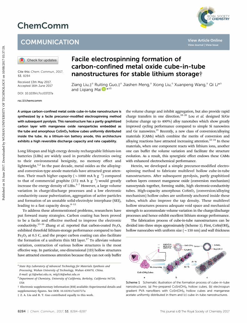
Herein, we developed a simple precursor-modified electro-spinning method to fabricate multilevel hollow cube-in-tubenanostructures. After subsequent pyrolysis, partly graphitizedcarbon layers connect manganese oxide (conversion mechanism)nanocrystals together, forming stable, high electronic-conductivitytubes. High-capacity amorphous CoSnO3 (conversion/alloyingmechanism) hollow cubes are uniformly anchored inside thesetubes, which also improve the tap density. These multilevelhollow structures possess adequate void space and mechanicalstrength to accommodate volume variation in the charge/dischargeprocesses and hence exhibit excellent lithium storage performance.
The fabrication process of cube-in-tube nanostructures can bedivided into three steps approximately (Scheme 1). First, CoSn(OH)6
hollow nanocubes with uniform size (B150 nm) and wall thickness
Scheme 1 Schematic illustration of the formation process of cube-in-tubenanostructures. (a) Pre-prepared CoSn(OH)6 hollow cubes, (b) electrospungradient PVA nanofibers with CoSn(OH)6 hollow cubes and manganeseacetate uniformly distributed in them and (c) cube-in-tube nanostructures.
a State Key Laboratory of Advanced Technology for Materials Synthesis and
Processing, Wuhan University of Technology, Wuhan 430070, China.
E-mail: [email protected], [email protected] Department of Chemistry, University of California, Berkeley, California 94720,
USA
† Electronic supplementary information (ESI) available: Experimental details andsupplementary figures. See DOI: 10.1039/c7cc03727a‡ Z. A. Liu and R. T. Guo contributed equally to this work.
Received 13th May 2017,Accepted 16th June 2017
DOI: 10.1039/c7cc03727a
rsc.li/chemcomm
ChemComm
COMMUNICATION
Publ
ishe
d on
16
June
201
7. D
ownl
oade
d by
WU
HA
N U
NIV
ER
SIT
Y O
F T
EC
HN
OL
OG
Y o
n 10
/08/
2017
03:
37:5
9.
View Article OnlineView Journal | View Issue
This journal is©The Royal Society of Chemistry 2017 Chem. Commun., 2017, 53, 8284--8287 | 8285
(B15 nm) were obtained through a co-precipitation method atroom temperature (Fig. S1, ESI†).4 Then, the pre-prepared hollownanocube powder was added into a transparent precursorsolution of high-/middle-/low-molecular-weight poly(vinyl alcohol)(HMW-/MMW-/LMW-PVAs) and manganese acetate for electro-spinning. After that, PVAs were distributed into three layersalong the radial direction in the composite fibers, which hasbeen proved in our previous works.25,26 Hollow cubes and manga-nese acetate were spread in the fibers uniformly (Scheme 1b) and ananotube has not been formed at this stage (Fig. S2a, ESI†).According to Fig. S2d, ESI,† all the peaks of these composite fibersin the X-ray powder diffraction (XRD) pattern can be indexedto pure CoSn(OH)6. The as-prepared nanofibers were then pre-sintered at 300 1C in air for 1 h, forming carbon-confinednanotubes with manganese oxide (Mn3O4) spreading in thecarbon layers (Fig. S2b, ESI†), while the nanocubes stayed in thecenter of the nanotubes because of their relatively large volumeand high weight (Scheme 1c). The corresponding XRD patternshows the formation of the Mn3O4 phase (Fig. S2e, ESI†).Finally, partly graphitized carbon tubes with manganese oxidesembedded in the outer layers and CoSnO3 hollow cubes uni-formly anchored inside the tubes were obtained after sinteringat 450 1C under an argon atmosphere for 1 h. The conversion ofpartial Mn3O4 to MnO was also observed in the XRD patternafter the graphitization process, which may result from thereducibility of carbon (Fig. S2f, ESI†). By contrast, when man-ganese acetate was removed from the precursor solution, theouter nanotube could not be maintained in the sintering processes(Fig. S4, ESI†). Moreover, it is important that the diameter of thenanotubes should well match with the size of the nanocubes toenable the successful fabrication of the nanostructure (Fig. S3, ESI†).
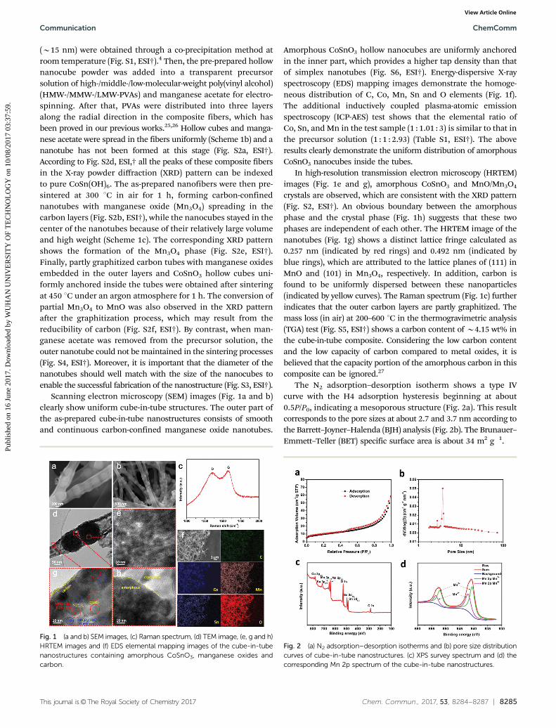
Scanning electron microscopy (SEM) images (Fig. 1a and b)clearly show uniform cube-in-tube structures. The outer part ofthe as-prepared cube-in-tube nanostructures consists of smoothand continuous carbon-confined manganese oxide nanotubes.
Amorphous CoSnO3 hollow nanocubes are uniformly anchoredin the inner part, which provides a higher tap density than thatof simplex nanotubes (Fig. S6, ESI†). Energy-dispersive X-rayspectroscopy (EDS) mapping images demonstrate the homoge-neous distribution of C, Co, Mn, Sn and O elements (Fig. 1f).The additional inductively coupled plasma-atomic emissionspectroscopy (ICP-AES) test shows that the elemental ratio ofCo, Sn, and Mn in the test sample (1 : 1.01 : 3) is similar to that inthe precursor solution (1 : 1 : 2.93) (Table S1, ESI†). The aboveresults clearly demonstrate the uniform distribution of amorphousCoSnO3 nanocubes inside the tubes.
In high-resolution transmission electron microscopy (HRTEM)images (Fig. 1e and g), amorphous CoSnO3 and MnO/Mn3O4
crystals are observed, which are consistent with the XRD pattern(Fig. S2, ESI†). An obvious boundary between the amorphousphase and the crystal phase (Fig. 1h) suggests that these twophases are independent of each other. The HRTEM image of thenanotubes (Fig. 1g) shows a distinct lattice fringe calculated as0.257 nm (indicated by red rings) and 0.492 nm (indicated byblue rings), which are attributed to the lattice planes of (111) inMnO and (101) in Mn3O4, respectively. In addition, carbon isfound to be uniformly dispersed between these nanoparticles(indicated by yellow curves). The Raman spectrum (Fig. 1c) furtherindicates that the outer carbon layers are partly graphitized. Themass loss (in air) at 200–600 1C in the thermogravimetric analysis(TGA) test (Fig. S5, ESI†) shows a carbon content of B4.15 wt% inthe cube-in-tube composite. Considering the low carbon contentand the low capacity of carbon compared to metal oxides, it isbelieved that the capacity portion of the amorphous carbon in thiscomposite can be ignored.27
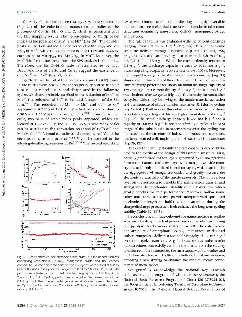
The N2 adsorption–desorption isotherm shows a type IVcurve with the H4 adsorption hysteresis beginning at about0.5P/P0, indicating a mesoporous structure (Fig. 2a). This resultcorresponds to the pore sizes at about 2.7 and 3.7 nm according tothe Barrett–Joyner–Halenda (BJH) analysis (Fig. 2b). The Brunauer–Emmett–Teller (BET) specific surface area is about 34 m2 g�1.
Fig. 1 (a and b) SEM images, (c) Raman spectrum, (d) TEM image, (e, g and h)HRTEM images and (f) EDS elemental mapping images of the cube-in-tubenanostructures containing amorphous CoSnO3, manganese oxides andcarbon.
Fig. 2 (a) N2 adsorption–desorption isotherms and (b) pore size distributioncurves of cube-in-tube nanostructures. (c) XPS survey spectrum and (d) thecorresponding Mn 2p spectrum of the cube-in-tube nanostructures.
Communication ChemComm
Publ
ishe
d on
16
June
201
7. D
ownl
oade
d by
WU
HA
N U
NIV
ER
SIT
Y O
F T
EC
HN
OL
OG
Y o
n 10
/08/
2017
03:
37:5
9.
View Article Online
8286 | Chem. Commun., 2017, 53, 8284--8287 This journal is©The Royal Society of Chemistry 2017
The X-ray photoelectron spectroscopy (XPS) survey spectrum(Fig. 2c) of the cube-in-tube nanostructures indicates thepresence of Co, Sn, Mn, O and C, which is consistent withthe EDS mapping results. The deconvolution of Mn 2p peaksindicates the presence of Mn2+ and Mn3+ (Fig. 2d). The doubletpeaks at 640.3 eV and 651.9 eV correspond to Mn 2p3/2 and Mn2p1/2 in Mn2+, while the doublet peaks at 641.4 eV and 653.5 eVcorrespond to Mn 2p3/2 and Mn 2p1/2 in Mn3+. Moreover, theMn3+/Mn2+ ratio measured from the XPS analysis is about 1 : 2.Therefore, the Mn3O4/MnO ratio is estimated to be 1 : 3.Deconvolutions of Sn 3d and Co 2p suggest the existence ofonly Sn4+ and Co2+ (Fig. S7, ESI†).
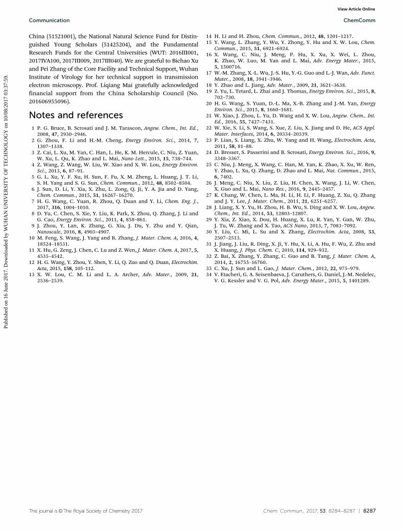
Fig. 3a shows the initial three cyclic voltammetry (CV) scans.In the initial cycle, obvious reduction peaks appeared at about0.78 V, 0.63 V and 0.10 V and disappeared in the followingcycles, which are probably ascribed to the reduction of Mn3+ toMn2+, the reduction of Sn4+ to Sn0 and formation of the SEIfilm.28,29 The reduction of Mn2+ to Mn0 and Co2+ to Co0
appeared at 0.2 V and 1.04 V in the first scan and shifted to0.30 V and 1.25 V in the following cycles.29,30 From the secondcycle, two pairs of stable redox peaks appeared, which arelocated at 1.25 V/2.10 V and 0.35 V/1.35 V. These redox peakscan be ascribed to the conversion reactions of Co0/Co2+ andMn0/Mn2+.28–32 A broad cathodic band extending to 0 V and thecorresponding anodic peak at 0.55 V can be ascribed to thealloying/de-alloying reaction of Sn0.33,34 The second and third
CV curves almost overlapped, indicating a highly reversiblenature of the electrochemical reactions in the cube-in-tube nano-structures containing amorphous CoSnO3, manganese oxidesand carbon.
The rate capability was evaluated with the current densitiesranging from 0.1 to 5 A g�1 (Fig. 3b). This cube-in-tubestructure delivers average discharge capacities of 960, 796,621, 484, 374 and 301 mA h g�1 at current densities of 0.1,0.2, 0.5, 1, 2 and 5 A g�1. When the current density returns to0.1 A g�1, the discharge capacity returns to 1081 mA h g�1,indicating a high capacity recovery rate of over 100%. Moreover,the charge/discharge curve at different current densities (Fig. 3d)shows small polarization of this active material. Furthermore, lowcurrent cycling performance shows an initial discharge capacity of1296 mA h g�1 at a current density of 0.1 A g�1, and 1071 mA h g�1
was obtained after 50 cycles (Fig. 3c). The capacity increases after20 cycles, which may be owing to the anode material activationand the decrease of charge transfer resistance (Rct) during cycling(Fig. S8, ESI†). Furthermore, this cube-in-tube nanostructure showsan outstanding cycling stability at a high current density of 2 A g�1
(Fig. 3e). The initial discharge capacity is 463 mA h g�1 and acapacity of 368 mA h g�1 is retained after 1500 cycles. The SEMimage of the cube-in-tube nanocomposites after the cycling testindicates that the structure of hollow nanocubes and nanotubeshas been retained well, implying the high stability of the structure(Fig. S9, ESI†).
The excellent cycling stability and rate capability can be attrib-uted to the merits of the design of this unique structure. First,partially graphitized carbon layers generated by in situ pyrolysisform a continuous conductive layer with manganese oxide nano-crystals uniformly embedded in carbon layers, which can inhibitthe aggregation of manganese oxides and greatly increase theelectronic conductivity of the anode materials. The thin carbonlayer on the surface also benefits the axial electron transfer andstrengthens the mechanical stability of the nanotubes, whichgreatly benefits the rate performance. Moreover, hollow nano-cubes and stable nanotubes provide adequate void space andmechanical strength to buffer volume variation during thecharge/discharge processes, which enhance the long-term cyclingstability (Table S2, ESI†).
In conclusion, a unique cube-in-tube nanostructure is synthe-sized via a facile approach of precursor-modified electrospinningand pyrolysis. As the anode material for LIBs, the cube-in-tubenanostructure of amorphous CoSnO3, manganese oxides andcarbon composites delivers a reversible capacity of 368 mA h g�1
over 1500 cycles even at 2 A g�1. These unique cube-in-tubenanostructures successfully combine the merits from the stabilityof carbon-confined nanotubes, the high capacity of nanocubes andthe hollow structure which efficiently buffers the volume variation,providing a new strategy to enhance the lithium storage perfor-mance of metal oxides.
We gratefully acknowledge the National Key Researchand Development Program of China (2016YFA0202603), theNational Basic Research Program of China (2013CB934103),the Programme of Introducing Talents of Discipline to Univer-sities (B17034), the National Natural Science Foundation of
Fig. 3 Electrochemical performance of the cube-in-tube nanostructurescontaining amorphous CoSnO3, manganese oxide and the carboncomposite. (a) The first three consecutive CV cycles were tested at a scanrate of 0.2 mV s�1 in a potential range from 0.01 to 3.0 V vs. Li+/Li. (b) Rateperformance tested at the current densities ranging from 0.1 to 0.2, 0.5, 1,2 and 5 A g�1. (c) Cycling performance tested at the current density of0.1 A g�1. (d) The charge/discharge curves at various current densities.(e) Cycling performance and Coulombic efficiency tested at the currentdensity of 2 A g�1.
ChemComm Communication
Publ
ishe
d on
16
June
201
7. D
ownl
oade
d by
WU
HA
N U
NIV
ER
SIT
Y O
F T
EC
HN
OL
OG
Y o
n 10
/08/
2017
03:
37:5
9.
View Article Online
This journal is©The Royal Society of Chemistry 2017 Chem. Commun., 2017, 53, 8284--8287 | 8287
China (51521001), the National Natural Science Fund for Distin-guished Young Scholars (51425204), and the FundamentalResearch Funds for the Central Universities (WUT: 2016III001,2017IVA100, 2017III009, 2017III040). We are grateful to Bichao Xuand Pei Zhang of the Core Facility and Technical Support, WuhanInstitute of Virology for her technical support in transmissionelectron microscopy. Prof. Liqiang Mai gratefully acknowledgedfinancial support from the China Scholarship Council (No.201606955096).
Notes and references1 P. G. Bruce, B. Scrosati and J. M. Tarascon, Angew. Chem., Int. Ed.,
2008, 47, 2930–2946.2 G. Zhou, F. Li and H.-M. Cheng, Energy Environ. Sci., 2014, 7,
1307–1338.3 Z. Cai, L. Xu, M. Yan, C. Han, L. He, K. M. Hercule, C. Niu, Z. Yuan,
W. Xu, L. Qu, K. Zhao and L. Mai, Nano Lett., 2015, 15, 738–744.4 Z. Wang, Z. Wang, W. Liu, W. Xiao and X. W. Lou, Energy Environ.
Sci., 2013, 6, 87–91.5 G. L. Xu, Y. F. Xu, H. Sun, F. Fu, X. M. Zheng, L. Huang, J. T. Li,
S. H. Yang and S. G. Sun, Chem. Commun., 2012, 48, 8502–8504.6 J. Sun, D. Li, Y. Xia, X. Zhu, L. Zong, Q. Ji, Y. A. Jia and D. Yang,
Chem. Commun., 2015, 51, 16267–16270.7 H. G. Wang, C. Yuan, R. Zhou, Q. Duan and Y. Li, Chem. Eng. J.,
2017, 316, 1004–1010.8 D. Yu, C. Chen, S. Xie, Y. Liu, K. Park, X. Zhou, Q. Zhang, J. Li and
G. Cao, Energy Environ. Sci., 2011, 4, 858–861.9 J. Zhou, Y. Lan, K. Zhang, G. Xia, J. Du, Y. Zhu and Y. Qian,
Nanoscale, 2016, 8, 4903–4907.10 M. Feng, S. Wang, J. Yang and B. Zhang, J. Mater. Chem. A, 2016, 4,
18524–18531.11 X. Hu, G. Zeng, J. Chen, C. Lu and Z. Wen, J. Mater. Chem. A, 2017, 5,
4535–4542.12 H. G. Wang, Y. Zhou, Y. Shen, Y. Li, Q. Zuo and Q. Duan, Electrochim.
Acta, 2015, 158, 105–112.13 X. W. Lou, C. M. Li and L. A. Archer, Adv. Mater., 2009, 21,
2536–2539.
14 H. Li and H. Zhou, Chem. Commun., 2012, 48, 1201–1217.15 Y. Wang, L. Zhang, Y. Wu, Y. Zhong, Y. Hu and X. W. Lou, Chem.
Commun., 2015, 51, 6921–6924.16 X. Wang, C. Niu, J. Meng, P. Hu, X. Xu, X. Wei, L. Zhou,
K. Zhao, W. Luo, M. Yan and L. Mai, Adv. Energy Mater., 2015,5, 1500716.
17 W.-M. Zhang, X.-L. Wu, J.-S. Hu, Y.-G. Guo and L.-J. Wan, Adv. Funct.Mater., 2008, 18, 3941–3946.
18 Y. Zhao and L. Jiang, Adv. Mater., 2009, 21, 3621–3638.19 Z. Yu, L. Tetard, L. Zhai and J. Thomas, Energy Environ. Sci., 2015, 8,
702–730.20 H. G. Wang, S. Yuan, D.-L. Ma, X.-B. Zhang and J.-M. Yan, Energy
Environ. Sci., 2015, 8, 1660–1681.21 W. Xiao, J. Zhou, L. Yu, D. Wang and X. W. Lou, Angew. Chem., Int.
Ed., 2016, 55, 7427–7431.22 W. Xie, S. Li, S. Wang, S. Xue, Z. Liu, X. Jiang and D. He, ACS Appl.
Mater. Interfaces, 2014, 6, 20334–20339.23 P. Lian, S. Liang, X. Zhu, W. Yang and H. Wang, Electrochim. Acta,
2011, 58, 81–88.24 D. Bresser, S. Passerini and B. Scrosati, Energy Environ. Sci., 2016, 9,
3348–3367.25 C. Niu, J. Meng, X. Wang, C. Han, M. Yan, K. Zhao, X. Xu, W. Ren,
Y. Zhao, L. Xu, Q. Zhang, D. Zhao and L. Mai, Nat. Commun., 2015,6, 7402.
26 J. Meng, C. Niu, X. Liu, Z. Liu, H. Chen, X. Wang, J. Li, W. Chen,X. Guo and L. Mai, Nano Res., 2016, 9, 2445–2457.
27 K. Chang, W. Chen, L. Ma, H. Li, H. Li, F. Huang, Z. Xu, Q. Zhangand J. Y. Lee, J. Mater. Chem., 2011, 21, 6251–6257.
28 J. Liang, X. Y. Yu, H. Zhou, H. B. Wu, S. Ding and X. W. Lou, Angew.Chem., Int. Ed., 2014, 53, 12803–12807.
29 Y. Xia, Z. Xiao, X. Dou, H. Huang, X. Lu, R. Yan, Y. Gan, W. Zhu,J. Tu, W. Zhang and X. Tao, ACS Nano, 2013, 7, 7083–7092.
30 Y. Liu, C. Mi, L. Su and X. Zhang, Electrochim. Acta, 2008, 53,2507–2513.
31 J. Jiang, J. Liu, R. Ding, X. Ji, Y. Hu, X. Li, A. Hu, F. Wu, Z. Zhu andX. Huang, J. Phys. Chem. C, 2010, 114, 929–932.
32 Z. Bai, X. Zhang, Y. Zhang, C. Guo and B. Tang, J. Mater. Chem. A,2014, 2, 16755–16760.
33 C. Xu, J. Sun and L. Gao, J. Mater. Chem., 2012, 22, 975–979.34 V. Etacheri, G. A. Seisenbaeva, J. Caruthers, G. Daniel, J.-M. Nedelec,
V. G. Kessler and V. G. Pol, Adv. Energy Mater., 2015, 5, 1401289.
Communication ChemComm
Publ
ishe
d on
16
June
201
7. D
ownl
oade
d by
WU
HA
N U
NIV
ER
SIT
Y O
F T
EC
HN
OL
OG
Y o
n 10
/08/
2017
03:
37:5
9.
View Article Online