Embed Size (px)
Citation preview
Face Detection in the Near-IR Spectrum
Jonathan Dowdall Ioannis Pavlidis* George Bebis University of Nevada, Reno University of Houston University of Nevada, Reno Dept. of Computer Science Dept. of Computer Science Dept. of Computer Science Computer Vision Laboratory Visual Computing Laboratory Computer Vision Laboratory [email protected] [email protected] [email protected]
* To whom all correspondence should be addressed.
Abstract Face detection is an important prerequisite step for successful face recognition. The performance of previous face detection methods reported in the literature is far from perfect and deteriorates ungracefully where lighting conditions cannot be controlled. We propose a method that outperforms state-of-the-art face detection methods in environments with stable lighting. In addition, our method can potentially perform well in environments with variable lighting conditions. The approach capitalizes upon our near-IR skin detection method reported elsewhere [13][14]. It ascertains the existence of a face within the skin region by finding the eyes and eyebrows. The eye-eyebrow pairs are determined by extracting appropriate features from multiple near-IR bands. Very successful feature extraction is achieved by simple algorithmic means like integral projections and template matching. This is because processing is constrained in the skin region and aided by the near-IR phenomenology. The effectiveness of our method is substantiated by comparative experimental results with the Identix face detector [5]. 1. Introduction
Face detection and recognition have been active research areas for more than thirty years. Face detection is an important preprocessing stage of an overall face recognition system. Although, it may appear rudimentary to a layman, face detection is a challenging machine vision operation, particularly in outdoor or semi-outdoor environments where illumination varies greatly. This is one of the primary reasons that face recognition is currently constrained to access control applications in indoor settings.
There is a pressing need for expanding the application of face recognition technologies to surveillance and monitoring scenarios. Such systems would be most advantageous in the context of
protecting high value assets (e.g. perimeter of government buildings) from asymmetric (terrorist) threats. They will also be advantageous in gate control points to automate the validation of incoming personnel in military bases. A major technical challenge that needs to be addressed in these directions is the low performance of face detectors in rather unconstrained environments. Visible-band face detectors, as those reported in the literature, opt for pure algorithmic solutions into inherent phenomenology problems. Human facial signatures vary significantly across races in the visible band. This variability coupled with dynamic lighting conditions present a formidable problem. Reducing light variability through the use of an artificial illuminator is rather awkward in the visible band because it may be distracting to the eyes of the people in the scene and reveals the existence of the surveillance system.
In the current paper we present a novel face detection system based on near-IR phenomenology, and multi-band feature extraction. Facial signatures are less variable in near-IR aiding significantly the detection work. Illumination in the scene can be maintained at an optimal level through a feedback control loop that adjusts a near-IR illuminator. Since, near-IR light is invisible to the human eye the system can remain unobtrusive and covert. The above advantages in combination with the unique reflectance characteristics of the human skin in the near-IR spectrum allow for simple algorithmic-based face detection methods to perform extremely well.
The results of the present research will be incorporated in a prototype face verification system for gate control in a U.S. Naval Base in Hawaii. The system will use our face detector and the face recognition engine FaceIt of Identix to automatically verify the identity of incoming personnel. According to the application scenario the driver will stop his vehicle, lower his window, and turn his head towards the triple-band system. The
system will acquire the driver’s facial image and verify it against the corresponding stored image. The ID emitted from the driver’s RF badge will index the stored image. Depending on the verification result the gate will open or an alarm will go off. Although, the target application is relatively constrained, it is an order of magnitude more challenging than the current indoors access control scenarios.
The rest of the paper is organized as follows: In Section 2 we give an overview of previous work done in the area of face detection. In Section 3 we give a top-level description of the hardware and software architecture of our face detection system. In Section 4 we describe the Frame Acquisition module. In Sections 5, 6, and 7 we describe the software modules of the illumination feedback control loop. In Section 8 we provide a brief description of our skin detection method. In Section 9 we elaborate on our face detection method, which builds upon our skin detection method. In Section 10 we present and discuss the experimental results. Finally, in Section 11 we conclude the paper and present our plans for future work. 2. Previous Work
In recent years a sizable body of research in the area of face detection has been amassed. An excellent survey of the relevant literature can be found in [1]. The methodologies vary, but the research mainly centers around three different approaches: feature invariant approaches, appearance-based approaches, and wavelet analysis. Each of these approaches has its respective strengths and weaknesses when applied to face detection, but none has yet been able to attain results rivaling human perception.
The majority of face detection research aims to find structural features that exist even when the pose and viewpoint vary. The existence of such features is associated with the existence of faces in the image. Feature extraction methods utilize various properties of the face and skin to isolate and extract desired data. Popular methods include skin color segmentation [2][3], principal component analysis [4][5], eigenspace modeling [6], histogram analysis [7], texture analysis [8], and frequency domain features [9].
Appearance-based approaches for face detection typically involve some kind of neural network. In these approaches, detection is based on learned models from a representative data set. Finding a representative data set is difficult. This difficulty is compounded by the fact that a strong counter example set must also be compiled to train
the individual networks. Despite these obstacles many of the most promising results have been reported from research involving artificial neural networks. In his work Rowley et al. [10] used an arbitration method among several networks to improve performance. His system produced some impressive results for forward facing subjects.
Wavelet analysis is the newest of the face detection approaches under discussion. The general aim of the wavelet approach is maximum class discrimination and signal dimensionality reduction [11]. Due to the reduced dimensionality, wavelet-based methods are computationally efficient.
All of the above approaches are associated with visible spectrum imagery. Therefore, they are susceptible to light changes [12] and the variability of human facial appearance in the visible band. A distinct line of research pursued by our group proposed the fusion of two near-IR bands for the detection of face and other exposed skin areas of the body [13][14]. The method capitalizes upon some unique properties of the human skin in the near-IR spectrum. Our dual-band system maintains an optimal illumination in the scene through the liberal use of artificial non-distracting near-IR lights. As a result, the system performs superb skin detection both in indoor and outdoor settings. In the present paper, we report further algorithmic work that accurately locates the face within the detected skin region.
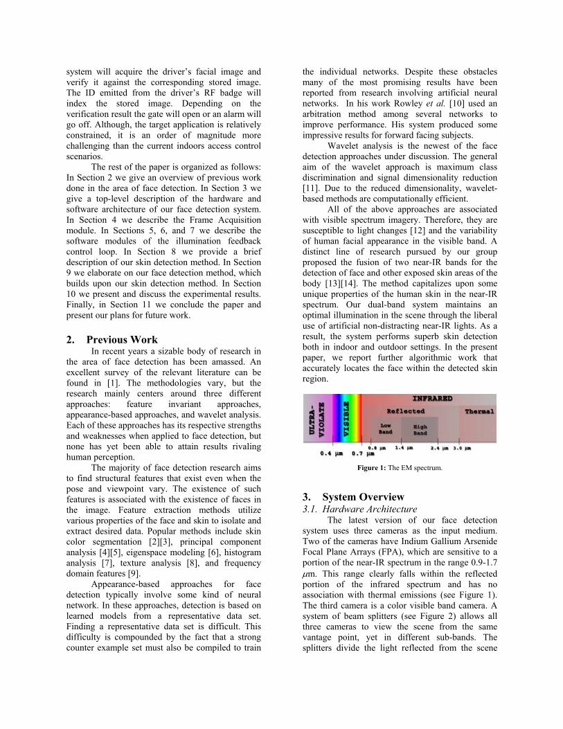
Figure 1: The EM spectrum.
3. System Overview 3.1. Hardware Architecture
The latest version of our face detection system uses three cameras as the input medium. Two of the cameras have Indium Gallium Arsenide Focal Plane Arrays (FPA), which are sensitive to a portion of the near-IR spectrum in the range 0.9-1.7 µm. This range clearly falls within the reflected portion of the infrared spectrum and has no association with thermal emissions (see Figure 1). The third camera is a color visible band camera. A system of beam splitters (see Figure 2) allows all three cameras to view the scene from the same vantage point, yet in different sub-bands. The splitters divide the light reflected from the scene
into the visible band beam (0.3-0.6 µm), the lower band beam (0.8-1.4 µm), and the upper band beam (1.4-2.4 µm). The three beams are funneled to the FPAs of the corresponding cameras. Each camera is connected to a frame grabber, which digitizes the incoming video.
Although we have designed and implemented a tri-band system we use only the two near-IR bands in our approach. At the moment, we use the visible band only for comparative testing purposes with the Identix face detection and recognition software [5].
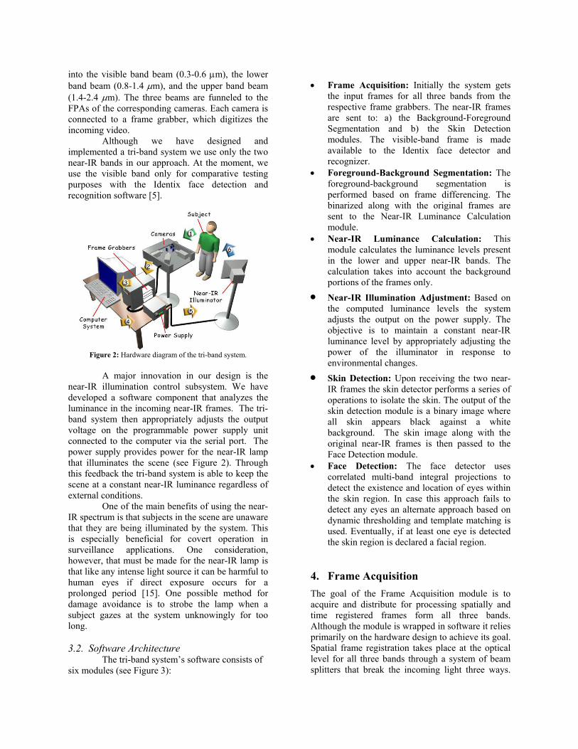
Figure 2: Hardware diagram of the tri-band system.
A major innovation in our design is the
near-IR illumination control subsystem. We have developed a software component that analyzes the luminance in the incoming near-IR frames. The tri-band system then appropriately adjusts the output voltage on the programmable power supply unit connected to the computer via the serial port. The power supply provides power for the near-IR lamp that illuminates the scene (see Figure 2). Through this feedback the tri-band system is able to keep the scene at a constant near-IR luminance regardless of external conditions.
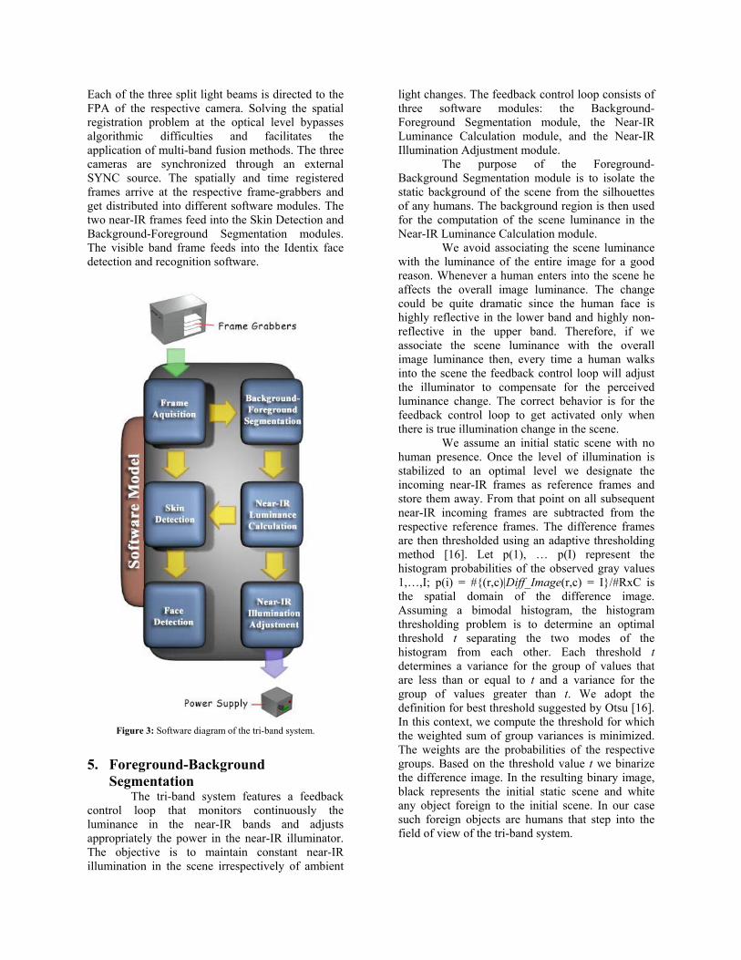
One of the main benefits of using the near-IR spectrum is that subjects in the scene are unaware that they are being illuminated by the system. This is especially beneficial for covert operation in surveillance applications. One consideration, however, that must be made for the near-IR lamp is that like any intense light source it can be harmful to human eyes if direct exposure occurs for a prolonged period [15]. One possible method for damage avoidance is to strobe the lamp when a subject gazes at the system unknowingly for too long. 3.2. Software Architecture The tri-band system’s software consists of six modules (see Figure 3):
• Frame Acquisition: Initially the system gets
the input frames for all three bands from the respective frame grabbers. The near-IR frames are sent to: a) the Background-Foreground Segmentation and b) the Skin Detection modules. The visible-band frame is made available to the Identix face detector and recognizer.
• Foreground-Background Segmentation: The foreground-background segmentation is performed based on frame differencing. The binarized along with the original frames are sent to the Near-IR Luminance Calculation module.
• Near-IR Luminance Calculation: This module calculates the luminance levels present in the lower and upper near-IR bands. The calculation takes into account the background portions of the frames only.
• Near-IR Illumination Adjustment: Based on the computed luminance levels the system adjusts the output on the power supply. The objective is to maintain a constant near-IR luminance level by appropriately adjusting the power of the illuminator in response to environmental changes.
• Skin Detection: Upon receiving the two near-IR frames the skin detector performs a series of operations to isolate the skin. The output of the skin detection module is a binary image where all skin appears black against a white background. The skin image along with the original near-IR frames is then passed to the Face Detection module.
• Face Detection: The face detector uses correlated multi-band integral projections to detect the existence and location of eyes within the skin region. In case this approach fails to detect any eyes an alternate approach based on dynamic thresholding and template matching is used. Eventually, if at least one eye is detected the skin region is declared a facial region.
4. Frame Acquisition The goal of the Frame Acquisition module is to acquire and distribute for processing spatially and time registered frames form all three bands. Although the module is wrapped in software it relies primarily on the hardware design to achieve its goal. Spatial frame registration takes place at the optical level for all three bands through a system of beam splitters that break the incoming light three ways.
Each of the three split light beams is directed to the FPA of the respective camera. Solving the spatial registration problem at the optical level bypasses algorithmic difficulties and facilitates the application of multi-band fusion methods. The three cameras are synchronized through an external SYNC source. The spatially and time registered frames arrive at the respective frame-grabbers and get distributed into different software modules. The two near-IR frames feed into the Skin Detection and Background-Foreground Segmentation modules. The visible band frame feeds into the Identix face detection and recognition software.
Figure 3: Software diagram of the tri-band system.
5. Foreground-Background
Segmentation The tri-band system features a feedback
control loop that monitors continuously the luminance in the near-IR bands and adjusts appropriately the power in the near-IR illuminator. The objective is to maintain constant near-IR illumination in the scene irrespectively of ambient
light changes. The feedback control loop consists of three software modules: the Background-Foreground Segmentation module, the Near-IR Luminance Calculation module, and the Near-IR Illumination Adjustment module.
The purpose of the Foreground-Background Segmentation module is to isolate the static background of the scene from the silhouettes of any humans. The background region is then used for the computation of the scene luminance in the Near-IR Luminance Calculation module.
We avoid associating the scene luminance with the luminance of the entire image for a good reason. Whenever a human enters into the scene he affects the overall image luminance. The change could be quite dramatic since the human face is highly reflective in the lower band and highly non-reflective in the upper band. Therefore, if we associate the scene luminance with the overall image luminance then, every time a human walks into the scene the feedback control loop will adjust the illuminator to compensate for the perceived luminance change. The correct behavior is for the feedback control loop to get activated only when there is true illumination change in the scene.
We assume an initial static scene with no human presence. Once the level of illumination is stabilized to an optimal level we designate the incoming near-IR frames as reference frames and store them away. From that point on all subsequent near-IR incoming frames are subtracted from the respective reference frames. The difference frames are then thresholded using an adaptive thresholding method [16]. Let p(1), … p(I) represent the histogram probabilities of the observed gray values 1,…,I; p(i) = #{(r,c)|Diff_Image(r,c) = I}/#RxC is the spatial domain of the difference image. Assuming a bimodal histogram, the histogram thresholding problem is to determine an optimal threshold t separating the two modes of the histogram from each other. Each threshold t determines a variance for the group of values that are less than or equal to t and a variance for the group of values greater than t. We adopt the definition for best threshold suggested by Otsu [16]. In this context, we compute the threshold for which the weighted sum of group variances is minimized. The weights are the probabilities of the respective groups. Based on the threshold value t we binarize the difference image. In the resulting binary image, black represents the initial static scene and white any object foreign to the initial scene. In our case such foreign objects are humans that step into the field of view of the tri-band system.
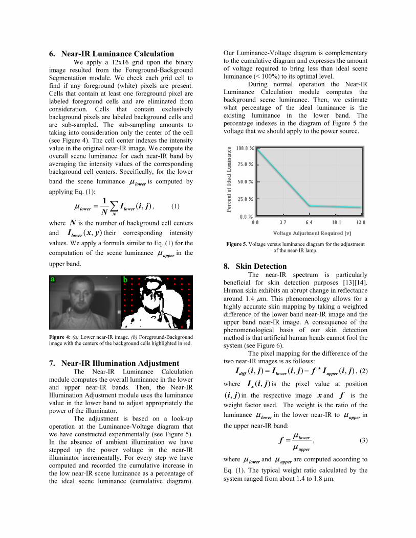
6. Near-IR Luminance Calculation We apply a 12x16 grid upon the binary
image resulted from the Foreground-Background Segmentation module. We check each grid cell to find if any foreground (white) pixels are present. Cells that contain at least one foreground pixel are labeled foreground cells and are eliminated from consideration. Cells that contain exclusively background pixels are labeled background cells and are sub-sampled. The sub-sampling amounts to taking into consideration only the center of the cell (see Figure 4). The cell center indexes the intensity value in the original near-IR image. We compute the overall scene luminance for each near-IR band by averaging the intensity values of the corresponding background cell centers. Specifically, for the lower band the scene luminance lowerµ is computed by applying Eq. (1):
( , )lower lowerN
I i jN
µ = ∑1, (1)
where N is the number of background cell centers and ( , )lowerI x y their corresponding intensity values. We apply a formula similar to Eq. (1) for the computation of the scene luminance upperµ in the upper band.
Figure 4: (a) Lower near-IR image. (b) Foreground-Background image with the centers of the background cells highlighted in red.
7. Near-IR Illumination Adjustment
The Near-IR Luminance Calculation module computes the overall luminance in the lower and upper near-IR bands. Then, the Near-IR Illumination Adjustment module uses the luminance value in the lower band to adjust appropriately the power of the illuminator.
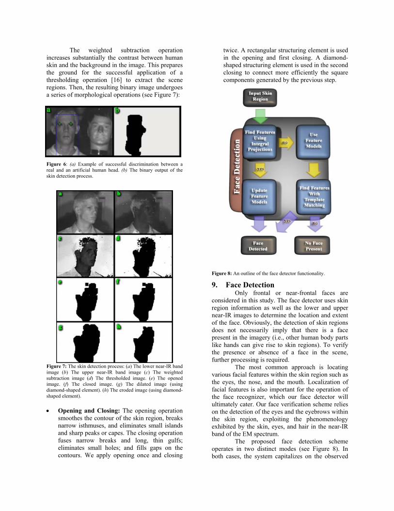
The adjustment is based on a look-up operation at the Luminance-Voltage diagram that we have constructed experimentally (see Figure 5). In the absence of ambient illumination we have stepped up the power voltage in the near-IR illuminator incrementally. For every step we have computed and recorded the cumulative increase in the low near-IR scene luminance as a percentage of the ideal scene luminance (cumulative diagram).
Our Luminance-Voltage diagram is complementary to the cumulative diagram and expresses the amount of voltage required to bring less than ideal scene luminance (< 100%) to its optimal level.
During normal operation the Near-IR Luminance Calculation module computes the background scene luminance. Then, we estimate what percentage of the ideal luminance is the existing luminance in the lower band. The percentage indexes in the diagram of Figure 5 the voltage that we should apply to the power source.
Figure 5. Voltage versus luminance diagram for the adjustment of the near-IR lamp.
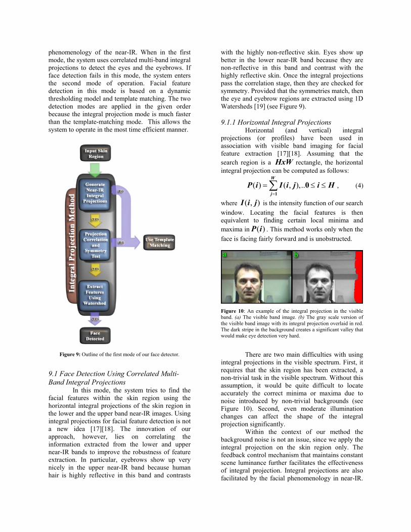
8. Skin Detection The near-IR spectrum is particularly beneficial for skin detection purposes [13][14]. Human skin exhibits an abrupt change in reflectance around 1.4 µm. This phenomenology allows for a highly accurate skin mapping by taking a weighted difference of the lower band near-IR image and the upper band near-IR image. A consequence of the phenomenological basis of our skin detection method is that artificial human heads cannot fool the system (see Figure 6).
The pixel mapping for the difference of the two near-IR images is as follows: ( , ) ( , ) ( , )diff lower upperI i j I i j f I i j= − * , (2)
where ( , )xI i j is the pixel value at position
( , )i j in the respective image x and f is the weight factor used. The weight is the ratio of the luminance lowerµ in the lower near-IR to upperµ in the upper near-IR band:
lower
upper
f µµ
= , (3)
where lowerµ and upperµ are computed according to Eq. (1). The typical weight ratio calculated by the system ranged from about 1.4 to 1.8 µm.
The weighted subtraction operation increases substantially the contrast between human skin and the background in the image. This prepares the ground for the successful application of a thresholding operation [16] to extract the scene regions. Then, the resulting binary image undergoes a series of morphological operations (see Figure 7):
Figure 6: (a) Example of successful discrimination between a real and an artificial human head. (b) The binary output of the skin detection process.
Figure 7: The skin detection process: (a) The lower near-IR band image (b) The upper near-IR band image (c) The weighted subtraction image (d) The thresholded image. (e) The opened image. (f) The closed image. (g) The dilated image (using diamond-shaped element). (h) The eroded image (using diamond-shaped element). • Opening and Closing: The opening operation
smoothes the contour of the skin region, breaks narrow isthmuses, and eliminates small islands and sharp peaks or capes. The closing operation fuses narrow breaks and long, thin gulfs; eliminates small holes; and fills gaps on the contours. We apply opening once and closing
twice. A rectangular structuring element is used in the opening and first closing. A diamond-shaped structuring element is used in the second closing to connect more efficiently the square components generated by the previous step.
Figure 8: An outline of the face detector functionality.
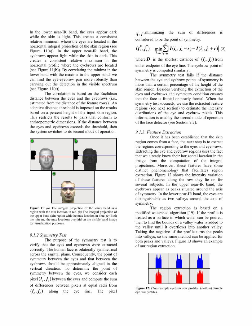
9. Face Detection Only frontal or near-frontal faces are considered in this study. The face detector uses skin region information as well as the lower and upper near-IR images to determine the location and extent of the face. Obviously, the detection of skin regions does not necessarily imply that there is a face present in the imagery (i.e., other human body parts like hands can give rise to skin regions). To verify the presence or absence of a face in the scene, further processing is required. The most common approach is locating various facial features within the skin region such as the eyes, the nose, and the mouth. Localization of facial features is also important for the operation of the face recognizer, which our face detector will ultimately cater. Our face verification scheme relies on the detection of the eyes and the eyebrows within the skin region, exploiting the phenomenology exhibited by the skin, eyes, and hair in the near-IR band of the EM spectrum. The proposed face detection scheme operates in two distinct modes (see Figure 8). In both cases, the system capitalizes on the observed
phenomenology of the near-IR. When in the first mode, the system uses correlated multi-band integral projections to detect the eyes and the eyebrows. If face detection fails in this mode, the system enters the second mode of operation. Facial feature detection in this mode is based on a dynamic thresholding model and template matching. The two detection modes are applied in the given order because the integral projection mode is much faster than the template-matching mode. This allows the system to operate in the most time efficient manner.
Figure 9: Outline of the first mode of our face detector.
9.1 Face Detection Using Correlated Multi-Band Integral Projections In this mode, the system tries to find the facial features within the skin region using the horizontal integral projections of the skin region in the lower and the upper band near-IR images. Using integral projections for facial feature detection is not a new idea [17][18]. The innovation of our approach, however, lies on correlating the information extracted from the lower and upper near-IR bands to improve the robustness of feature extraction. In particular, eyebrows show up very nicely in the upper near-IR band because human hair is highly reflective in this band and contrasts
with the highly non-reflective skin. Eyes show up better in the lower near-IR band because they are non-reflective in this band and contrast with the highly reflective skin. Once the integral projections pass the correlation stage, then they are checked for symmetry. Provided that the symmetries match, then the eye and eyebrow regions are extracted using 1D Watersheds [19] (see Figure 9). 9.1.1 Horizontal Integral Projections Horizontal (and vertical) integral projections (or profiles) have been used in association with visible band imaging for facial feature extraction [17][18]. Assuming that the search region is a HxW rectangle, the horizontal integral projection can be computed as follows:
( ) ( , ),..W
jP i I i j i H
=
= ≤ ≤∑1
0 , (4)
where ( , )I i j is the intensity function of our search window. Locating the facial features is then equivalent to finding certain local minima and maxima in ( )P i . This method works only when the face is facing fairly forward and is unobstructed.
Figure 10: An example of the integral projection in the visible band. (a) The visible band image. (b) The gray scale version of the visible band image with its integral projection overlaid in red. The dark stripe in the background creates a significant valley that would make eye detection very hard.
There are two main difficulties with using
integral projections in the visible spectrum. First, it requires that the skin region has been extracted, a non-trivial task in the visible spectrum. Without this assumption, it would be quite difficult to locate accurately the correct minima or maxima due to noise introduced by non-trivial backgrounds (see Figure 10). Second, even moderate illumination changes can affect the shape of the integral projection significantly. Within the context of our method the background noise is not an issue, since we apply the integral projection on the skin region only. The feedback control mechanism that maintains constant scene luminance further facilitates the effectiveness of integral projection. Integral projections are also facilitated by the facial phenomenology in near-IR.
In the lower near-IR band, the eyes appear dark while the skin is light. This creates a consistent relative minimum where the eyes are located in the horizontal integral projection of the skin region (see Figure 11(a)). In the upper near-IR band, the eyebrows appear light while the skin is dark. This creates a consistent relative maximum in the horizontal profile where the eyebrows are located (see Figure 11(b)). By correlating the minima in the lower band with the maxima in the upper band, we can find the eye-eyebrow pair more robustly than carrying out the detection in the visible spectrum (see Figure 11(c)). The correlation is based on the Euclidean distance between the eyes and the eyebrows (i.e., estimated from the distance of the feature rows). An adaptive distance threshold is imposed on the results based on a percent height of the input skin region. This restricts the results to pairs that conform to anthropometric dimensions. If the distance between the eyes and eyebrows exceeds the threshold, then the system switches to its second mode of operation.
Figure 11: (a) The integral projection of the lower band skin region with the min location in red. (b) The integral projection of the upper band skin region with the max location in blue. (c) Both the min and the max locations overlaid on the visible band image for visualization purposes.
9.1.2 Symmetry Test The purpose of the symmetry test is to verify that the eyes and eyebrows were extracted correctly. The human face is bilaterally symmetrical across the sagittal plane. Consequently, the point of symmetry between the eyes and that between the eyebrows should be approximately aligned in the vertical direction. To determine the point of symmetry between the eyes, we consider each pixel ( , )c ci j between the eyes and compute the sum of differences between pixels at equal radii from ( , )c ci j along the eye line. The pixel
**
( , )c c
ji minimizing the sum of differences is
considered to be the point of symmetry:
( , )
**( , ) ( , ) ( , )min=
= − − +∑0c c
D
c c c c cci j r
I i j r I i j rji ,(5)
where D is the shortest distance of ( , )c ci j from either endpoint of the eye line. The eyebrow point of symmetry is computed similarly. The symmetry test fails if the distance between the eye and eyebrow points of symmetry is more than a certain percentage of the height of the skin region. Besides verifying the extraction of the eyes and eyebrows, the symmetry condition ensures that the face is frontal or nearly frontal. When the symmetry test succeeds, we use the extracted feature regions (see next section) to estimate the intensity distributions of the eye and eyebrow pixels. This information is used by the second mode of operation of the face detector (see Section 9.2). 9.1.3. Feature Extraction Once it has been established that the skin region comes from a face, the next step is to extract the regions corresponding to the eyes and eyebrows. Extracting the eye and eyebrow regions uses the fact that we already know their horizontal location in the image from the computation of the integral projections. Moreover, these features have some distinct phenomenology that facilitates region extraction. Figure 12 shows the intensity variation of these features along the row they lie on for several subjects. In the upper near-IR band, the eyebrows appear as peaks situated around the axis of symmetry. In the lower near-IR band, the eyes are distinguishable as two valleys around the axis of symmetry.
The region extraction is based on a modified watershed algorithm [19]. If the profile is treated as a surface in which water can be poured, then to find the bounds of a valley water is added to the valley until it overflows into another valley. Taking the negative of the profile turns the peaks into valleys, so the same method can be applied for both peaks and valleys. Figure 13 shows an example of our region extraction.
Figure 12: (Top) Sample eyebrow row profiles. (Bottom) Sample eye row profiles.
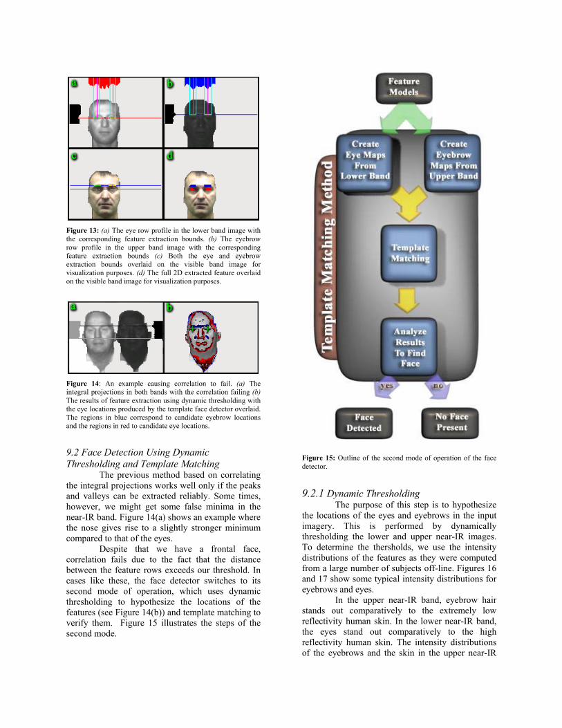
Figure 13: (a) The eye row profile in the lower band image with the corresponding feature extraction bounds. (b) The eyebrow row profile in the upper band image with the corresponding feature extraction bounds (c) Both the eye and eyebrow extraction bounds overlaid on the visible band image for visualization purposes. (d) The full 2D extracted feature overlaid on the visible band image for visualization purposes.
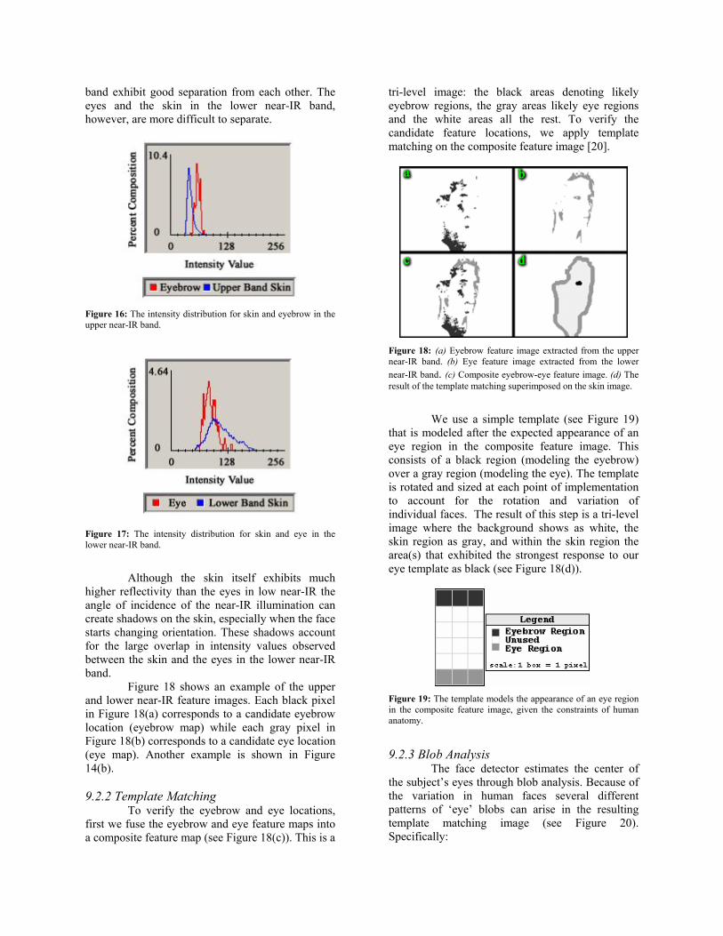
Figure 14: An example causing correlation to fail. (a) The integral projections in both bands with the correlation failing (b) The results of feature extraction using dynamic thresholding with the eye locations produced by the template face detector overlaid. The regions in blue correspond to candidate eyebrow locations and the regions in red to candidate eye locations.
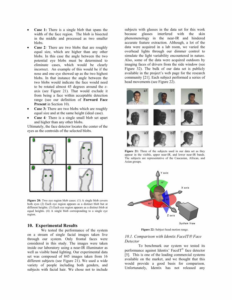
9.2 Face Detection Using Dynamic Thresholding and Template Matching The previous method based on correlating the integral projections works well only if the peaks and valleys can be extracted reliably. Some times, however, we might get some false minima in the near-IR band. Figure 14(a) shows an example where the nose gives rise to a slightly stronger minimum compared to that of the eyes. Despite that we have a frontal face, correlation fails due to the fact that the distance between the feature rows exceeds our threshold. In cases like these, the face detector switches to its second mode of operation, which uses dynamic thresholding to hypothesize the locations of the features (see Figure 14(b)) and template matching to verify them. Figure 15 illustrates the steps of the second mode.
Figure 15: Outline of the second mode of operation of the face detector.
9.2.1 Dynamic Thresholding The purpose of this step is to hypothesize the locations of the eyes and eyebrows in the input imagery. This is performed by dynamically thresholding the lower and upper near-IR images. To determine the thersholds, we use the intensity distributions of the features as they were computed from a large number of subjects off-line. Figures 16 and 17 show some typical intensity distributions for eyebrows and eyes.
In the upper near-IR band, eyebrow hair stands out comparatively to the extremely low reflectivity human skin. In the lower near-IR band, the eyes stand out comparatively to the high reflectivity human skin. The intensity distributions of the eyebrows and the skin in the upper near-IR
band exhibit good separation from each other. The eyes and the skin in the lower near-IR band, however, are more difficult to separate.
Figure 16: The intensity distribution for skin and eyebrow in the upper near-IR band.
Figure 17: The intensity distribution for skin and eye in the lower near-IR band.
Although the skin itself exhibits much higher reflectivity than the eyes in low near-IR the angle of incidence of the near-IR illumination can create shadows on the skin, especially when the face starts changing orientation. These shadows account for the large overlap in intensity values observed between the skin and the eyes in the lower near-IR band.
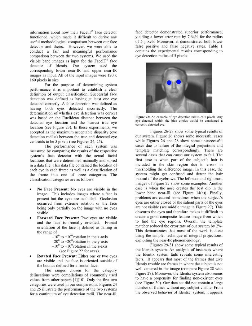
Figure 18 shows an example of the upper and lower near-IR feature images. Each black pixel in Figure 18(a) corresponds to a candidate eyebrow location (eyebrow map) while each gray pixel in Figure 18(b) corresponds to a candidate eye location (eye map). Another example is shown in Figure 14(b).
9.2.2 Template Matching To verify the eyebrow and eye locations, first we fuse the eyebrow and eye feature maps into a composite feature map (see Figure 18(c)). This is a
tri-level image: the black areas denoting likely eyebrow regions, the gray areas likely eye regions and the white areas all the rest. To verify the candidate feature locations, we apply template matching on the composite feature image [20].
Figure 18: (a) Eyebrow feature image extracted from the upper near-IR band. (b) Eye feature image extracted from the lower near-IR band. (c) Composite eyebrow-eye feature image. (d) The result of the template matching superimposed on the skin image.
We use a simple template (see Figure 19)
that is modeled after the expected appearance of an eye region in the composite feature image. This consists of a black region (modeling the eyebrow) over a gray region (modeling the eye). The template is rotated and sized at each point of implementation to account for the rotation and variation of individual faces. The result of this step is a tri-level image where the background shows as white, the skin region as gray, and within the skin region the area(s) that exhibited the strongest response to our eye template as black (see Figure 18(d)).
Figure 19: The template models the appearance of an eye region in the composite feature image, given the constraints of human anatomy.
9.2.3 Blob Analysis The face detector estimates the center of the subject’s eyes through blob analysis. Because of the variation in human faces several different patterns of ‘eye’ blobs can arise in the resulting template matching image (see Figure 20). Specifically:
• Case 1: There is a single blob that spans the width of the face region. The blob is bisected in the middle and processed as two smaller blobs.
• Case 2: There are two blobs that are roughly equal size, which are higher than any other blobs. In this case the angle between the two potential eye blobs must be determined to eliminate cases, which would be clearly incorrect. An example of this would be if the nose and one eye showed up as the two highest blobs. In that instance the angle between the two blobs would indicate the face would need to be rotated almost 45 degrees around the z-axis (see Figure 21). That would exclude it from being a face within acceptable detection range (see our definition of Forward Face Present in Section 10).
• Case 3: There are two blobs which are roughly equal size and at the same height (ideal case).
• Case 4: There is a single small blob set apart and higher than any other blobs.
Ultimately, the face detector locates the center of the eyes as the centroids of the selected blobs.
Figure 20: Two eye region blob cases: (1) A single blob covers both eyes (2) Each eye region appears as a distinct blob but at different heights. (3) Each eye region appears as a distinct blob at equal heights. (4) A single blob corresponding to a single eye region.
10. Experimental Results
We tested the performance of the system on a stream of single facial images taken live through our system. Only frontal faces were considered in this study. The images were taken inside our laboratory using a near-IR illuminator as well as visible band lighting. Our experimental data set was composed of 845 images taken from 16 different subjects (see Figure 21). We used a wide variety of people including both genders, and subjects with facial hair. We chose not to include
subjects with glasses in the data set for this work because glasses interfered with the skin phenomenology in the near-IR and hindered accurate feature extraction. Although, a lot of the data were acquired in a lab room, we varied the overhead lights through our dimmer control to simulate the light variability encountered in nature. Also, some of the data were acquired outdoors by imaging faces of drivers from the side window (see Figure 32). The bulk of our data set is publicly available in the project’s web page for the research community [21]. Each subject performed a series of head movements (see Figure 22).
Figure 21: Three of the subjects used in our data set as they appear in the visible, upper near-IR, and lower near-IR bands. The subjects are representative of the Caucasian, African, and Asian groups.
Figure 22: Subject head motion range.
10.1. Comparison with Identix FaceIT Face Detector To benchmark our system we tested its performance against Identix’ FaceIT face detector [5]. This is one of the leading commercial systems available on the market, and we thought that this would provide a good basis for comparison. Unfortunately, Identix has not released any
information about how their FaceIT face detector functioned, which made it difficult to derive any useful methodological comparison between our face detector and theirs. However, we were able to conduct a fair and meaningful performance comparison between the two systems. We used the visible band images as input for the FaceIT face detector of Identix. Our system used the corresponding lower near-IR and upper near-IR images as input. All of the input images were 120 x 160 pixels in size. For the purpose of determining system performance it is important to establish a clear definition of output classification. Successful face detection was defined as having at least one eye detected correctly. A false detection was defined as having both eyes detected incorrectly. The determination of whether eye detection was correct was based on the Euclidean distance between the detected eye location and the nearest true eye location (see Figure 23). In these experiments, we accepted as the maximum acceptable disparity (eye detection radius) between the true and detected eye centroids to be 5 pixels (see Figures 24, 25). The performance of each system was measured by comparing the results of the respective system’s face detector with the actual facial locations that were determined manually and stored in a data file. This data file contained the location of each eye in each frame as well as a classification of the frame into one of three categories. The classification categories are as follows: • No Face Present: No eyes are visible in the
image. This includes images where a face is present but the eyes are occluded. Occlusion occurred from extreme rotation or the face being only partially on the image with no eyes visible.
• Forward Face Present: Two eyes are visible and the face is frontally oriented. Frontal orientation of the face is defined as falling in the range of
–100 to +100 rotation in the x-axis –200 to +200 rotation in the y-axis –100 to +100 rotation in the z-axis
(see Figure 22 for axes). • Rotated Face Present: Either one or two eyes
are visible and the face is oriented outside of the bounds defined for a frontal face.
The ranges chosen for the category delineations were compilations of commonly used values from other papers [1][10]. Only the first two categories were used in our comparisons. Figures 24 and 25 illustrate the performance of the two systems for a continuum of eye detection radii. The near-IR
face detector demonstrated superior performance, yielding a lower error rate by 7.64% for the radius of 5 pixels. Moreover, it demonstrated both lower false positive and false negative rates. Table 1 contains the experimental results corresponding to eye detection radius of 5 pixels.
Figure 23: An example of eye detection radius of 5 pixels. Any eye detected within the blue circles would be considered a correctly detected eye.
Figures 26-28 show some typical results of our system. Figure 26 shows some successful cases while Figures 26 and 28 show some unsuccessful cases due to failure of the integral projections and template matching correspondingly. There are several cases that can cause our system to fail. The first case is when part of the subject’s hair is included in the skin region due to errors in thresholding the difference image. In this case, the system might get confused and detect the hair instead of the eyebrows. The leftmost and rightmost images of Figure 27 show some examples. Another case is when the nose creates the best dip in the lower band near-IR (see Figure 14(a)). Finally, problems are caused sometimes when the subject’s eyes are either closed or the salient parts of the eyes are not visible (see middle image in Figure 27). This obscures the eyes and therefore makes it difficult to create a good composite feature image from which to find the eye regions. Overall, the template matcher reduced the error rate of our system by 2%. This demonstrates that most of the work is done using the simpler technique of integral projections, exploiting the near-IR phenomenology. Figures 29-31 show some typical results of the Identix system. An analysis of instances where the Identix system fails reveals some interesting facts. It appears that most of the frames that give Identix trouble are frames in where the subject is not well centered in the image (compare Figure 28 with Figure 29). Moreover, the Identix system also seems to have a propensity for finding non-existent eyes (see Figure 30). Our data set did not contain a large number of frames without any subject visible. From the observed behavior of Identix’ system, it appears
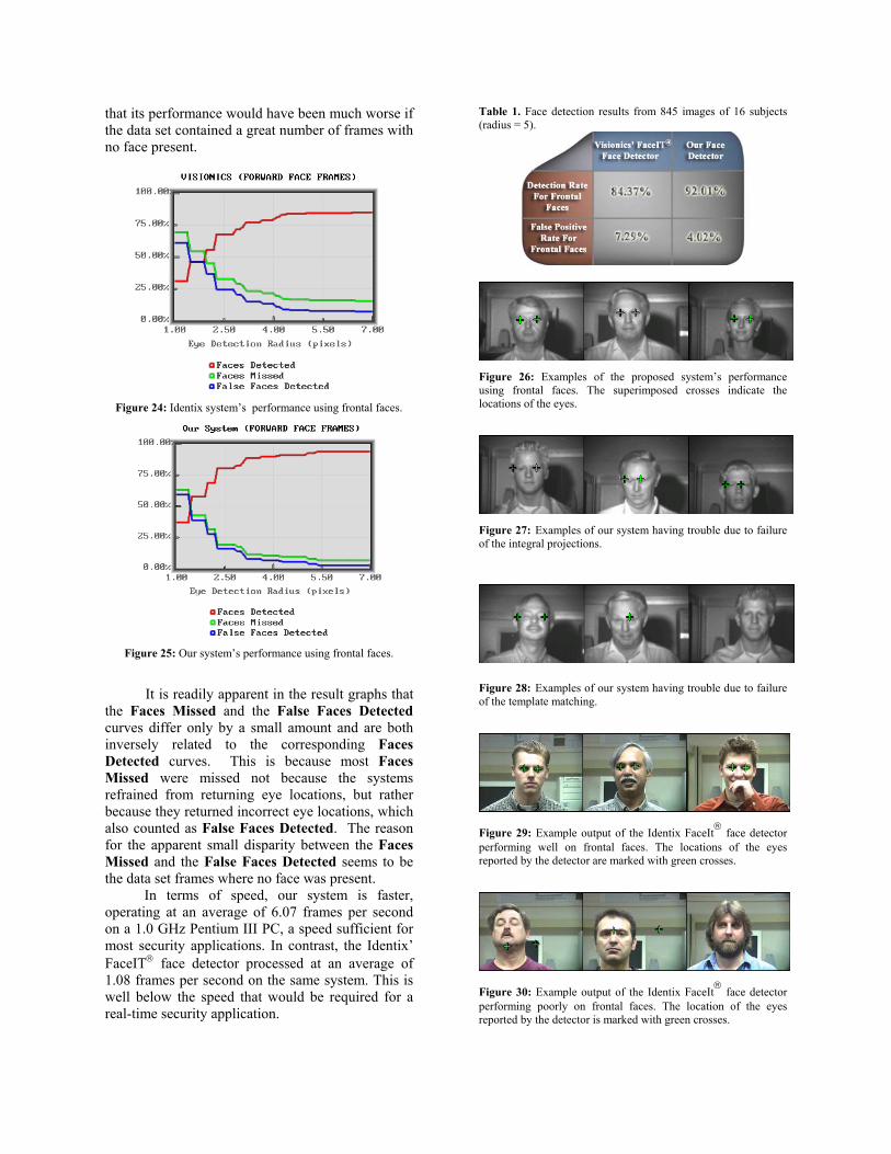
that its performance would have been much worse if the data set contained a great number of frames with no face present.
Figure 24: Identix system’s performance using frontal faces.
Figure 25: Our system’s performance using frontal faces.
It is readily apparent in the result graphs that the Faces Missed and the False Faces Detected curves differ only by a small amount and are both inversely related to the corresponding Faces Detected curves. This is because most Faces Missed were missed not because the systems refrained from returning eye locations, but rather because they returned incorrect eye locations, which also counted as False Faces Detected. The reason for the apparent small disparity between the Faces Missed and the False Faces Detected seems to be the data set frames where no face was present.
In terms of speed, our system is faster, operating at an average of 6.07 frames per second on a 1.0 GHz Pentium III PC, a speed sufficient for most security applications. In contrast, the Identix’ FaceIT face detector processed at an average of 1.08 frames per second on the same system. This is well below the speed that would be required for a real-time security application.
Table 1. Face detection results from 845 images of 16 subjects (radius = 5).
Figure 26: Examples of the proposed system’s performance using frontal faces. The superimposed crosses indicate the locations of the eyes.
Figure 27: Examples of our system having trouble due to failure of the integral projections.
Figure 28: Examples of our system having trouble due to failure of the template matching.
Figure 29: Example output of the Identix FaceIt face detector performing well on frontal faces. The locations of the eyes reported by the detector are marked with green crosses.
Figure 30: Example output of the Identix FaceIt face detector performing poorly on frontal faces. The location of the eyes reported by the detector is marked with green crosses.
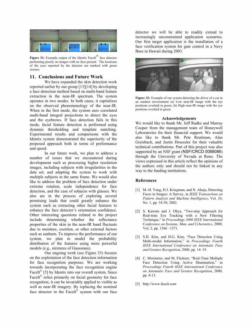
Figure 31: Example output of the Identix FaceIt face detector performing poorly on images with no face present. The locations of the eyes reported by the detector are marked with green crosses.
11. Conclusions and Future Work We have expanded the skin detection work reported earlier by our group [13][14] by developing a face detection method based on multi-band feature extraction in the near-IR spectrum. The system operates in two modes. In both cases, it capitalizes on the observed phenomenology of the near-IR. When in the first mode, the system uses correlated multi-band integral projections to detect the eyes and the eyebrows. If face detection fails in this mode, facial feature detection is performed using dynamic thresholding and template matching. Experimental results and comparisons with the Identix system demonstrated the superiority of the proposed approach both in terms of performance and speed.
In our future work, we plan to address a number of issues that we encountered during development such as processing higher resolution images, including subjects with irregularities in the data set, and adapting the system to work with multiple subjects in the same frame. We would also like to address the problem of face detection under extreme rotation, scale independence for face detection, and the case of subjects with glasses. We also are in the process of exploring several promising leads that could greatly enhance the system such as extracting other facial features to enhance the face detector’s orientation confidence. Other interesting questions related to the project include determining whether the reflectance properties of the skin in the near-IR band fluctuate due to moisture, exertion, or other external factors such as sunburn. To improve the performance of our system, we plan to model the probability distribution of the features using more powerful models (e.g., mixtures of Gaussians).
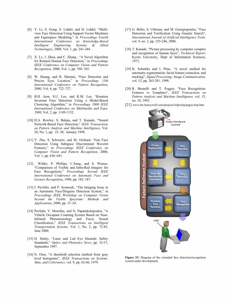
Our ongoing work (see Figure 33) focuses on the exploitation of the face detection information for face recognition purposes. We are working towards incorporating the face recognition engine FaceIt [5] by Identix into our overall system. Since FaceIt relies primarily on facial geometry for face recognition, it can be invariably applied to visible as well as near-IR imagery. By replacing the nominal face detector in the FaceIt system with our face
detector we will be able to readily extend to increasingly unconstrained application scenarios. Our first target application is the installation of a face verification system for gate control in a Navy Base in Hawaii during 2003.
Figure 32: Example of our system detecting the driver of a car in an outdoor environment (a) Low near-IR image with the eye positions overlaid in green, (b) High near-IR image with the eye positions overlaid in green.
Acknowledgements We would like to thank Mr. Jeff Radke and Murray Cooper from the management team of Honeywell Laboratories for their financial support. We would also like to thank Mr. Pete Reutiman, Alan Greisbach, and Justin Droessler for their valuable technical contributions. Part of this project was also supported by an NSF grant (NSF/CRCD 0088086) through the University of Nevada at Reno. The views expressed in this article reflect the opinions of the authors only and should not be linked in any way to the funding institutions. References [1] M.-H. Yang, D.J. Kriegman, and N. Ahuja, Detecting
Faces in Images: A Survey, in IEEE Transactions on Pattern Analysis and Machine Intelligence, Vol. 24, No. 1, pp. 34-58, 2002.
[2] S. Kawato and J. Ohya, “Two-step Approach for
Real-time Eye Tracking with a New Filtering Technique,” in Proceedings 2000 IEEE International Conference on Systems, Man, and Cybernetics, 2000, Vol. 2, pp. 1366 –1371.
[3] S.H. Kim, and H.G. Kim, “Face Detection Using
Multi-modal Information,” in Proceedings Fourth IEEE International Conference on Automatic Face and Gesture Recognition, 2000, pp. 14–19.
[4] C. Morimoto, and M. Flickner, “Real-Time Multiple
Face Detection Using Active Illumination,” in Proceedings Fourth IEEE International Conference on Automatic Face and Gesture Recognition, 2000, pp. 8-13.
[5] http://www.faceit.com
[6] Y. Li, S. Gong, S. Liddel, and H. Liddel, “Multi-view Face Detection Using Support Vector Machines and Eigenspace Modeling,” in Proceedings Fourth International Conference on Knowledge-Based Intelligent Engineering Systems & Allied Technologies, 2000, Vol. 1, pp. 241-244.
[7] X. Lv, J. Zhou, and C. Zhang , “A Novel Algorithm
for Rotated Human Face Detection,” in Proceedings IEEE Conference on Computer Vision and Pattern Recognition, 2000, Vol. 1, pp. 760–765.
[8] W. Huang, and R. Mariani, “Face Detection and
Precise Eyes Location,” in Proceedings 15th International Conference on Pattern Recognition, 2000, Vol. 4, pp. 722–727.
[9] B.H. Jeon, S.U. Lee, and K.M. Lee, “Rotation
Invariant Face Detection Using a Model-Based Clustering Algorithm,” in Proceedings 2000 IEEE International Conference on Multimedia and Expo, 2000, Vol. 2, pp. 1149-1152.
[10] H.A. Rowley, S. Baluja, and T. Kanade, “Neural
Network-Based Face Detection,” IEEE Transactions on Pattern Analysis and Machine Intelligence, Vol. 20, No. 1, pp. 23–38, January 1998.
[11] Y. Zhu, S. Schwartz, and M. Orchard, “Fast Face
Detection Using Subspace Discriminant Wavelet Features,” in Proceedings IEEE Conference on Computer Vision and Pattern Recognition, 2000, Vol. 1, pp. 636–641.
[12] . Wilder, P. Phillips, C.Jiang, and S. Wiener,
“Comparison of Visible and Infra-Red Imagery for Face Recognition,” Proceedings Second IEEE International Conference on Automatic Face and Gesture Recognition, 1996, pp. 182–187.
[13] I. Pavlidis, and P. Symosek, “The Imaging Issue in
an Automatic Face/Disguise Detection System,” in Proceedings IEEE Workshop on Computer Vision beyond the Visible Spectrum: Methods and Applications, 2000, pp. 15–24.
[14] Pavlidis, V. Morellas, and N. Papanikolopoulos, “A
Vehicle Occupant Counting System Based on Near-Infrared Phenomenology and Fuzzy Neural Classification,” IEEE Transactions on Intelligent Transportation Systems, Vol. 1, No. 2, pp. 72-85, June 2000.
[15] D. Sinley, “Laser and Led Eye Hazards: Safety
Standards,” Optics and Photonics News, pp. 32-37, September 1997.
[16] N. Otsu, “A threshold selection method from gray
level histograms”, IEEE Transactions on Systems, Man, and Cybernetics, vol. 9, pp. 62-66, 1979.
[17] G. Bebis, S. Uthiram, and M. Georgiopoulos, “Face Detection and Verification Using Genetic Search”, International Journal of Artificial Intelligence Tools, vol. 9, no. 2, pp. 225-246, 2000.
[18] T. Kanade, “Picture processing by computer complex
and recognition of human faces”, Technical Report, Kyoto University, Dept of Information Sciences, 1973.
[19] K. Sobottka and I. Pitas, “A novel method for
automatic segmentation, facial feature extraction, and tracking”, Signal Processing: Image Communication, vol. 12, pp. 263-281, 1998.
[20] R. Brunelli and T. Poggio, “Face Recognition:
Features vs Templates”, IEEE Transactions on Pattern Analysis and Machine Intelligence, vol. 15, no. 10, 1993.
[21] www.htc.honeywell.com/projects/iufp/nirp/pages/nirp.htm
Figure 33: Diagram of the extended face detection/recognition system under development.